13
ECUsim 2000 ECUsim 5100 Programming Manual PRELIMINARY

ECUsim 2000 ECUsim 5100
Programming Manual
PRELIMINARY
ECUsim 2000/5100
2 of 13 www.obdsol.com ECUSIMPMB
Information contained in this document is subject to change without notice. Trademarks are property of their respective owners. Copyright © 2013 OBD Solutions. All rights reserved.
Programming Manual
ECUSIMPMB www.obdsol.com 3 of 13
Table of Contents 1.0 Introduction .................................................................................................................................................................. 4
2.0 Commands .................................................................................................................................................................... 4
2.1 Command Summary ................................................................................................................................................. 4
2.2 General ECUsim Commands ..................................................................................................................................... 7
2.3 DTC Commands ........................................................................................................................................................ 7
2.4 ECU Commands ........................................................................................................................................................ 8
2.5 Freeze Frame Commands ......................................................................................................................................... 8
2.6 PID Commands ......................................................................................................................................................... 9
3.0 Event Messages .......................................................................................................................................................... 10
4.0 Error Messages ........................................................................................................................................................... 10
5.0 Examples ..................................................................................................................................................................... 11
5.1 Creating a Basic ECU ............................................................................................................................................... 11
5.2 Adding PIDs ............................................................................................................................................................ 11
5.3 Adding DTCs ........................................................................................................................................................... 12
5.4 Adding Freeze Frames ............................................................................................................................................ 12
5.5 Setting the VIN and CAL ID ..................................................................................................................................... 12
ECUsim 2000/5100
4 of 13 www.obdsol.com ECUSIMPMB
1.0 Introduction ECUsim 2000 and 5100 are software-configurable,
stand-alone benchtop OBD simulators. Internally, the objects (ECUs, DTCs, PIDs, and Freeze
Frames) are created dynamically at runtime, and stored in RAM. Consequently, objects can be created and deleted at will, but are lost after a software reset, or when power is removed. The high-level object hierarchy is:
ECUsim o ECUs
PIDs Fault Sets
DTCs Freeze Frames
When a parent object is deleted, all its child objects
are deleted as well. ECUsim object cannot be deleted. Certain objects can have multiple child objects. For
example, ECUsim can have multiple ECUs. In turn, each ECU can have multiple PIDs, DTCs, and Freeze Frames.
The number of objects that can be created depends on the size of the objects, and is limited by available RAM.
Objects have many user-settable properties (e.g., name, VIN, protocol preset). These properties can be set at run-time.
Most objects are self-explanatory, and their behavior is straightforward. Two important exceptions are the concepts of System-Managed ECUs and Fault Sets.
System-Managed ECUs have their relevant properties (active protocol preset, physical address, functional address, etc) updated automatically after a protocol switch is made (SP). Default ECUs are system-managed, but user-created ECUs are not. This attribute is controlled by the ESM command.
A Fault Set is a group of fault conditions, which define what happens when the user generates a fault event (by pressing the FAULT button, or issuing the SF command) and when the fault event is cleared via a Mode $04 OBD request. There are two fault sets defined for each ECU: “no fault” (0) and “fault” (1).
2.0 Commands
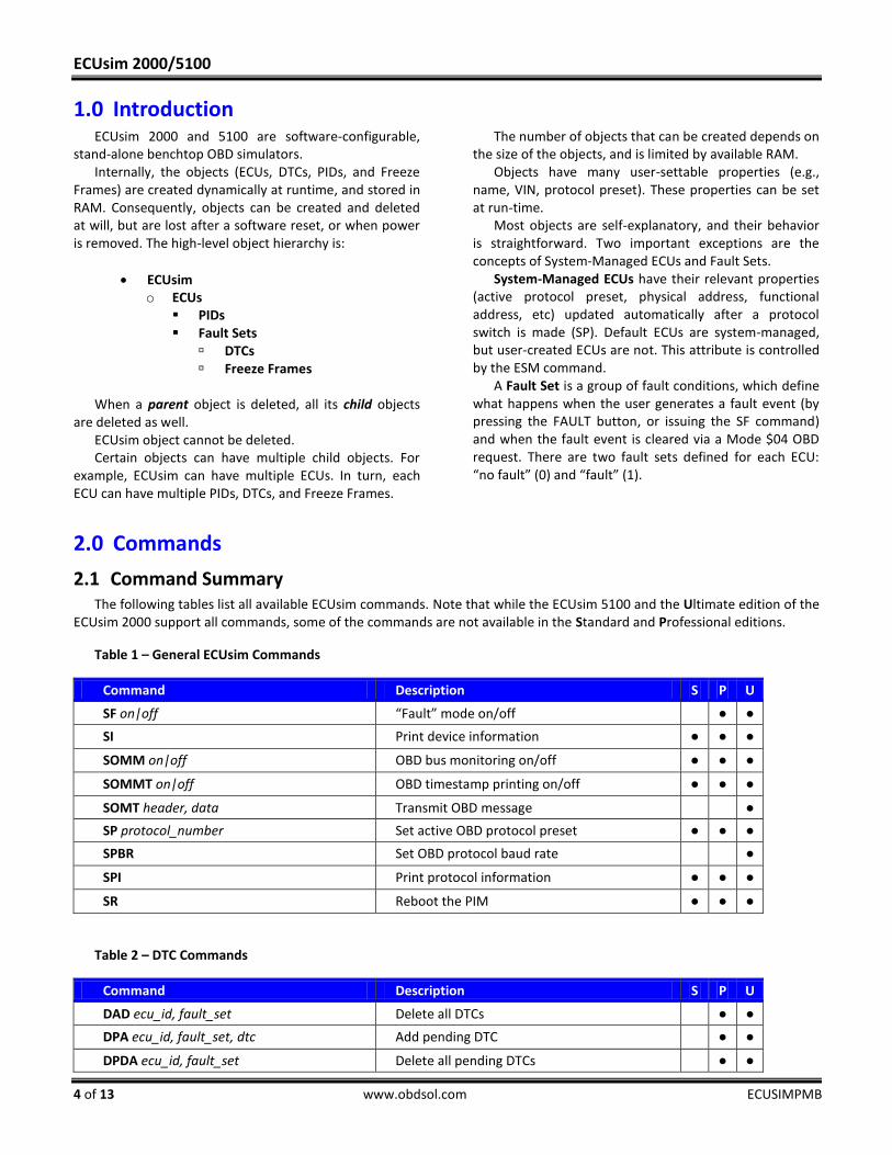
2.1 Command Summary The following tables list all available ECUsim commands. Note that while the ECUsim 5100 and the Ultimate edition of the
ECUsim 2000 support all commands, some of the commands are not available in the Standard and Professional editions.
Table 1 – General ECUsim Commands
Command Description S P U
SF on|off “Fault” mode on/off ● ●
SI Print device information ● ● ●
SOMM on|off OBD bus monitoring on/off ● ● ●
SOMMT on|off OBD timestamp printing on/off ● ● ●
SOMT header, data Transmit OBD message ●
SP protocol_number Set active OBD protocol preset ● ● ●
SPBR Set OBD protocol baud rate ●
SPI Print protocol information ● ● ●
SR Reboot the PIM ● ● ●
Table 2 – DTC Commands
Command Description S P U
DAD ecu_id, fault_set Delete all DTCs ● ●
DPA ecu_id, fault_set, dtc Add pending DTC ● ●
DPDA ecu_id, fault_set Delete all pending DTCs ● ●

Programming Manual
ECUSIMPMB www.obdsol.com 5 of 13
DRA ecu_id, fault_set, dtc Add permanent DTC ● ●
DRDA ecu_id, fault_set Delete all permanent DTCs ● ●
DSA ecu_id, fault_set, dtc Add stored DTC ● ●
DSDA ecu_id, fault_set Delete all stored DTCs ● ●
Table 3 – ECU Commands
Command Description S P U
E ecu_id, on|off Set ECU on or off ● ●
EA ecu_id Add new ECU ● ●
EAF ecu_id, functional_addr Set functional address ● ●
EAP ecu_id, physical_addr Set physical address ● ●
EAPA ecu_id, protocol, physical_addr, functional_addr, [can_id_type]
Add address pair to an ECU (for system managed ECUs)
● ●
EAUPP ecu_id, on/off Set auto update protocol properties on or off ● ●
EC ecu_id, “calid” Set calibration ID ● ●
ECD ecu_id Delete calibration ID ● ●
ED ecu_id Delete ECU ● ●
EDA Delete all ECUs ● ●
EL Print ECU list ● ● ●
EN ecu_id, “ecuname” Set ECU name ● ●
END ecu_id Delete name ● ●
EP ecu_id, preset Set protocol preset ● ●
EV ecu_id, “vin” Set VIN ● ●
EVD ecu_id Delete VIN ● ●
Table 4 – Freeze Frame Commands
Command Description S P U
FA ecu_id, fault_set, frame_num Add frame ● ●
FD ecu_id, fault_set, frame_num Delete frame ● ●
FPA ecu_id, fault_set, frame_num, pid_num, pid_data
Add PID to frame ● ●
FPD ecu_id, fault_set, frame_num, pid_num Delete PID from frame ● ●
FPSD ecu_id, fault_set, frame_num, pid_num, pid_data
Set frame’s PID to new value ● ●
FT ecu_id, fault_set, frame_num, dtc Set frame’s DTC ● ●
FTD ecu_id, fault_set, frame_num Delete DTC from frame ● ●
ECUsim 2000/5100
6 of 13 www.obdsol.com ECUSIMPMB
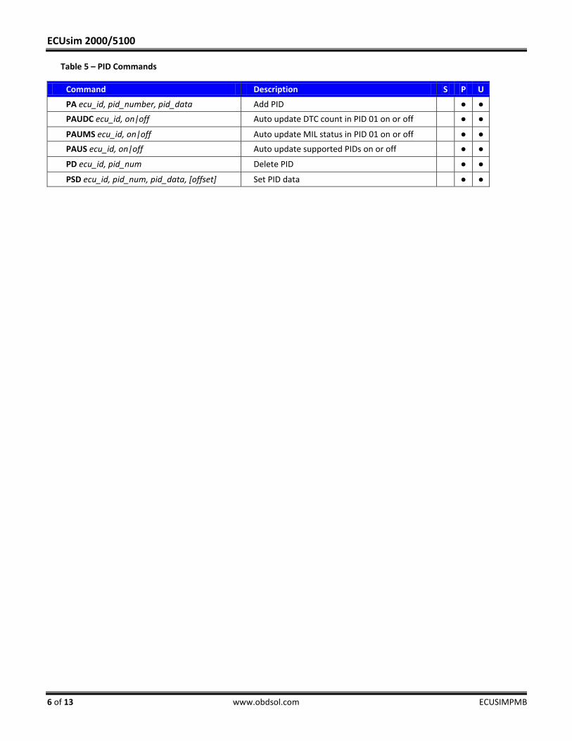
Table 5 – PID Commands
Command Description S P U
PA ecu_id, pid_number, pid_data Add PID ● ●
PAUDC ecu_id, on|off Auto update DTC count in PID 01 on or off ● ●
PAUMS ecu_id, on|off Auto update MIL status in PID 01 on or off ● ●
PAUS ecu_id, on|off Auto update supported PIDs on or off ● ●
PD ecu_id, pid_num Delete PID ● ●
PSD ecu_id, pid_num, pid_data, [offset] Set PID data ● ●
Programming Manual
ECUSIMPMB www.obdsol.com 7 of 13
2.2 General ECUsim CommandsSF on|off
Turn “Fault” mode on or off. Fault mode is off by default.
SOMM on|off Turn OBD bus monitoring on or off. OBD monitoring is
on by default.
SOMMT on|off Turn timestamp printing on or off. Timestamps are on
by default.
SOMT header, data Transmit OBD message. The message will be sent over
the active protocol set by the SP command.
SI Print device information.
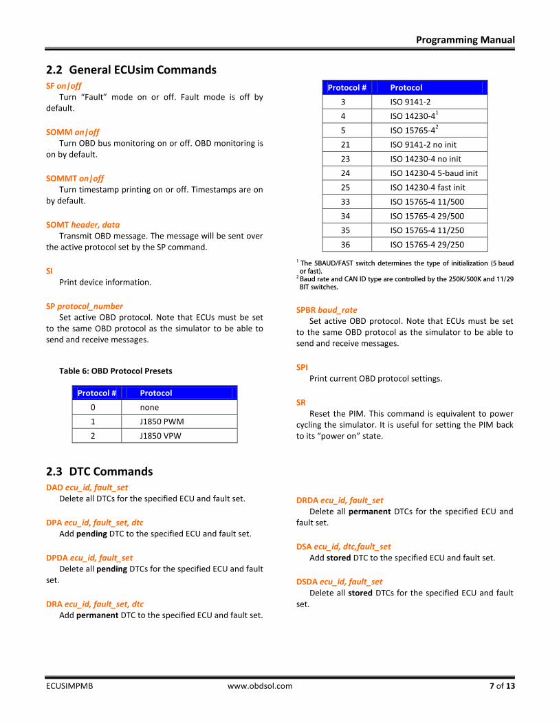
SP protocol_number Set active OBD protocol. Note that ECUs must be set
to the same OBD protocol as the simulator to be able to send and receive messages.
Table 6: OBD Protocol Presets
Protocol # Protocol
0 none
1 J1850 PWM
2 J1850 VPW
Protocol # Protocol
3 ISO 9141-2
4 ISO 14230-41
5 ISO 15765-42
21 ISO 9141-2 no init
23 ISO 14230-4 no init
24 ISO 14230-4 5-baud init
25 ISO 14230-4 fast init
33 ISO 15765-4 11/500
34 ISO 15765-4 29/500
35 ISO 15765-4 11/250
36 ISO 15765-4 29/250 1 The 5BAUD/FAST switch determines the type of initialization (5 baud or fast).
2 Baud rate and CAN ID type are controlled by the 250K/500K and 11/29 BIT switches.
SPBR baud_rate Set active OBD protocol. Note that ECUs must be set
to the same OBD protocol as the simulator to be able to send and receive messages.
SPI Print current OBD protocol settings.
SR Reset the PIM. This command is equivalent to power
cycling the simulator. It is useful for setting the PIM back to its “power on” state.
2.3 DTC Commands DAD ecu_id, fault_set
Delete all DTCs for the specified ECU and fault set.
DPA ecu_id, fault_set, dtc Add pending DTC to the specified ECU and fault set.
DPDA ecu_id, fault_set Delete all pending DTCs for the specified ECU and fault
set.
DRA ecu_id, fault_set, dtc Add permanent DTC to the specified ECU and fault set.
DRDA ecu_id, fault_set Delete all permanent DTCs for the specified ECU and
fault set.
DSA ecu_id, dtc,fault_set Add stored DTC to the specified ECU and fault set.
DSDA ecu_id, fault_set Delete all stored DTCs for the specified ECU and fault
set.
ECUsim 2000/5100
8 of 13 www.obdsol.com ECUSIMPMB
2.4 ECU Commands
E ecu_id, on|off Enable/disable specified ECU. This allows the user to
quickly remove an ECU from OBD communication, without affecting the ECU’s properties. User still has the ability to change the attributes of disabled ECUs (set VIN, add DTCs and PIDs, etc).
EA ecu_id Add an ECU. This command creates a blank ECU. To be
able to communicate with the ECU via OBD, configure it by setting the physical and functional addresses, CAN ID type (if applicable), protocol, and add PIDs and/or DTCs.
The ECU ID is a parameter required by most ECUsim commands. It must be unique, and once an ECU is created, its ID cannot be changed.
EAF ecu_id, functional_addr Set the functional address for the specified ECU.
EAP ecu_id, physical_addr Set the physical address of the specified ECU.
EAPA ecu_id, protocol, physical_addr, functional_addr, [can_id_type]
Add address pair to the specified ECU. Address pairs allow the simulator to update ECU protocol settings automatically, when user changes the active protocol of the simulator. Only one address pair is allowed per protocol. Enable system management (ESM) when using this command.
EAUPP ecu_id, on/off Set auto update protocol properties on or off. Auto
protocol properties allow the simulator to change the protocol of enabled ECUs when the SPx command is entered. When switching the protocol, a valid address pair must exist. If a valid address pair cannot be found, then the simulator will not change any of the ECUs attributes.
EC ecu_id, “calid” Set the Calibration ID number for the specified ECU
(Mode $09, SID $04). Maximum length of calid is 16 characters. Unused data bytes will be padded with $00.
ECD ecu_id Delete the Calibration ID number for the specified
ECU.
ED ecu_id Delete the specified ECU.
EDA Delete all ECUs.
EL Print ECU list.
EN ecu_id, “ecuname” Set the name of the specified ECU. Maximum length of
ecuname is 20 characters. Unused data bytes will be padded with $00.
END ecu_id Delete the name of the specified ECU.
EP ecu_id, protocol Set the protocol of the specified ECU. When using this
command, users are also required to set the physical and functional addresses and CAN id type (if applicable). Refer to the “SP” command definition for valid protocols.
EV ecu_id, vin Set the Vehicle Identification Number for the specified
ECU. Maximum length of vin is 17 characters. Unused data bytes will be padded with $00.
EVD ecu_id Delete the VIN for the specified ECU.
2.5 Freeze Frame Commands FA ecu_id, fault_set, frame_num
Add freeze frame to the specified ECU and fault set.
FD ecu_id, frame_num Delete the specified freeze frame.
FDA ecu_id, fault_set, frame_num, dtc Add a DTC to the specified freeze frame.
Programming Manual
ECUSIMPMB www.obdsol.com 9 of 13
FTD ecu_id, fault_set, frame_num Delete the DTC in the specified freeze frame.
FT ecu_id, fault_set, frame_num, dtc Set a specified frame’s DTC. This command is used to
change an existing DTC (created by the FDA command).
FPA ecu_id, fault_set, frame_num, pid_num, pid_data Add a PID to the specified freeze frame.
FPD ecu_id, fault_set, frame_num, pid_num Delete the specified PID
FPSD ecu_id, fault_set, frame_num, pid_num, pid_data Set the PID data for the specified freeze frame. This
command is used to change the data of an existing PID (created by the FPA command)
2.6 PID Commands PA ecu_id, pid_num, pid_data
Adds a new PID to the specified ECU.
PAUDC ecu_id, on|off Turn on/off auto updating of DTC count for PID 0x01.
PAUMS ecu_id, on|off Turn on/off auto-update of the MIL status flag in PID
0x01.
PAUS ecu_id, on|off Turn on/off auto-update of supported PIDs PIDs (PIDs
$00, $20, etc).
PD ecu_id, pid_num Delete PID from the specified ECU.
PSD ecu_id, pid_number, pid_data, [offset] Set the value of the specified PID. The offset refers to
the number of bytes to shift the PID’s value to the right. If pid_data exceeds the length of the PID data field, the command will be ignored.
ECUsim 2000/5100
10 of 13 www.obdsol.com ECUSIMPMB
3.0 Event Messages <MALFUNCTION EVENT>
Status message, indicates that a Fault Event was generated via the ‘Fault’ button press, or a software command.
<WAITING FOR 5 BAUD INIT> ECUsim is waiting for the OBD tester to start the 5-
baud ISO 9141 or ISO 14230 initialization sequence.
<WAITING FOR FAST INIT> ECUsim is waiting for the OBD tester to start the fast
ISO 14230 initialization sequence.
<5 BAUD INIT: OK> Detected a successful 5 baud initialization sequence.
<FAST INIT: OK> Detected a successful ISO 14230-4 fast initialization
sequence.
<ALL ECUS TIMED OUT> All virtual ECUs had timed out, because a supported
request had not been received within P3MAX (ISO 9141-2 and ISO 14230-4 protocols). <UART TX OVERFLOW>
UART transmit buffer overflow detected.
4.0 Error Messages CAN ERROR
The CAN peripheral had trouble transmitting or receiving messages. Possible causes include:
Device not connected to the CAN bus
Wrong protocol/CAN baud rate
Wiring problem
CMD NOT FOUND Unrecognized command.
ECU NOT FOUND Specified ECU does not exist.
INVALID Incorrect command syntax, or the command is not
appropriate for the context (e.g., send OBD message while the protocol is set to NONE).
INVALID PARAM COUNT Too few or too many parameters specified.
OUT OF MEMORY Not enough available RAM to complete the requested
operation.
PARAM ERROR Invalid parameter specified.
PROTOCOL LOCKED Unable to switch to the specified protocol, because
the protocol has not been enabled.
Programming Manual
ECUSIMPMB www.obdsol.com 11 of 13
5.0 Examples
5.1 Creating a Basic ECU In this example, we will create a basic custom ECU. This ECU will use the J1850 PWM protocol and support one PID (RPM). Notes:
After any reset, the simulator automatically creates default ECUs. Therefore, the first step is to delete the default ECUs.
The knobs are assigned to the first three ECUs (IDs $0, $1, and $2). We want to set the RPM to a fixed value, therefore we will use the next available ID ($3).
Here is the complete list of commands:
SP 1 set the simulator’s protocol to PWM EDA delete all existing (default) ECUs EA 3 create ECU #3 EN 3, “My ECU” specify ECU name EAP 3, 10 assign ECU physical address $10 EAF 3, 6A assign ECU functional address $6A EP 3, 1 set ECU’s protocol preset to PWM PA 3, 0C, 0FA0 create PID (RPM) and set its value to 1000 r/min E 3, on turn on the ECU
Send the EL (“list ECUs”) command to verify that the ECU has been created correctly. You should see the following
summary:
3 My ECU 10,6A
We can now request RPM to verify proper operation. Commands below assume that you’re using an STN11xx-based OBD tester (e.g., OBDLink SX or OBDLink MX):
>ATSP 1 set protocol to PWM OK >ATH 1 turn on message headers OK >01 0C send a request for RPM 41 6B 10 41 0C 0F A0 DE response from ECUsim
5.2 Adding PIDs Previous example already demonstrated how to add the PID for RPM ($0C). However, most OBD testers would not be
able to read out the RPM value, or even connect to the ECU, because the ECU will not respond to a PID $00 request. There are two ways to remedy this problem: either add the PID manually using the PA command, or use the PAUS command to have the ECU automatically create and update the “supported PIDs” PIDs ($00, $20, $40, etc) on as-needed basis.
We’ll use the PAUS command in this example, as we add PIDs for vehicle speed and fuel level. Assuming you’ve already set up a basic ECU from the previous example, enter the following commands:
PAUS 3, on enable auto-update of supported PIDs PA 3, 0D, 64 vehicle speed = 100 km/h PA 3, 2F, 80 fuel level = 50%
Use an OBD tester to confirm that the ECUsim automatically created and properly encoded PIDs $00 and $020:

ECUsim 2000/5100
12 of 13 www.obdsol.com ECUSIMPMB
>0100 request supported PIDs in the $01-$20 range 41 6B 10 41 00 00 18 00 01 95 >0120 request supported PIDs in the $21-$40 range 41 6B 10 41 20 00 02 00 00 5E
Notice that the PAUS command encoded the existing PID ($0C), as well as the new PIDs.
5.3 Adding DTCs ECUs can have stored, pending, and permanent DTCs. A given DTC can be added to either a “no fault” or “fault” fault set.
A “fault” event is generated when the user presses the “FAULT” button, or enters the SF on command. To add a stored DTC to the “fault” fault set, issue this command:
DSA 3, 1, P0100 report a stored DTC (P0100) after a fault event To automatically update DTC count and MIL status:
PAUDC 3, on enable automatic updates of stored DTC count PAUMS 3, on enable automatic updates of MIL status
If PID $01 does not exist, it will be automatically added to the ECU.
5.4 Adding Freeze Frames A freeze frame belongs to a fault set, has a frame number, and may contain PIDs and DTCs. In this example, we will create
a freeze frame that will be created after a “FAULT” event, and add one DTC and one PID:
FA 3, 1, 0 create freeze frame #0 for ECU ID=3 FT 3, 1, 0, P0100 add DTC (P0100) to freeze frame #0 FPA 3, 1, 0, 0C, 0FA0 add PID (RPM) to freeze frame #0
To verify, generate a “FAULT” event, and use OBDLink to send the commands:
>02 00 00 request supported PIDs in the $01-$20 range 41 6B 10 42 00 00 40 10 00 00 27 >02 02 00 request PID $02 (which DTC generated Freeze Frame?) 41 6B 10 42 02 00 01 00 58 >02 0C 00 request PID $0C (RPM) 41 6B 10 42 0C 00 0F A0 E3
5.5 Setting the VIN and CAL ID VIN and CAL ID are limited to 17 and 16 ASCII characters, respectively:
EV 3, “MyCustomVIN123456” EC 3, “MyCustomCALID 12”
Programming Manual
ECUSIMPMB www.obdsol.com 13 of 13
Revision History Appendix A:
Revision B (April 29, 2013)
Fixed header and footer alignments Renamed this document to ecusim-pm.pdf
Revision A (April 23, 2013)
Initial release of this document
Contact Information Appendix B:
OBD Solutions 1819 W Rose Garden Ln Ste 3 Phoenix, AZ 85027 United States Phone: +1 623.434.5506 Fax: +1 623.321.1628 Email: [email protected] Web: www.obdsol.com


