340
Edible Oil Processing

Edible Oil Processing

Edible Oil ProcessingSecond Edition
Edited by
Wolf HammHarpenden, UK
Richard J. HamiltonLiverpool John Moores University, Liverpool, UK
Gijs CalliauwDesmet Ballestra Oils and Fats, Zaventem, Belgium
A John Wiley & Sons, Ltd., Publication

This edition first published 2013© 2013 by John Wiley & Sons, Ltd
Wiley-Blackwell is an imprint of John Wiley & Sons, formed by the merger of Wiley’s globalScientific, Technical and Medical business with Blackwell Publishing.
Registered office:John Wiley & Sons, Ltd, The Atrium, Southern Gate, Chichester, West Sussex, PO19 8SQ, UK
Editorial offices:9600 Garsington Road, Oxford, OX4 2DQ, UKThe Atrium, Southern Gate, Chichester, West Sussex, PO19 8SQ, UK111 River Street, Hoboken, NJ 07030-5774, USA
For details of our global editorial offices, for customer services and for information about how toapply for permission to reuse the copyright material in this book please see our website atwww.wiley.com/wiley-blackwell.
The right of the author to be identified as the author of this work has been asserted in accordancewith the UK Copyright, Designs and Patents Act 1988.
All rights reserved. No part of this publication may be reproduced, stored in a retrieval system, ortransmitted, in any form or by any means, electronic, mechanical, photocopying, recording orotherwise, except as permitted by the UK Copyright, Designs and Patents Act 1988, without theprior permission of the publisher.
Designations used by companies to distinguish their products are often claimed as trademarks. Allbrand names and product names used in this book are trade names, service marks, trademarks orregistered trademarks of their respective owners. The publisher is not associated with any product orvendor mentioned in this book.
Limit of Liability/Disclaimer of Warranty: While the publisher and author(s) have used their bestefforts in preparing this book, they make no representations or warranties with respect to theaccuracy or completeness of the contents of this book and specifically disclaim any impliedwarranties of merchantability or fitness for a particular purpose. It is sold on the understanding thatthe publisher is not engaged in rendering professional services and neither the publisher nor theauthor shall be liable for damages arising herefrom. If professional advice or other expert assistanceis required, the services of a competent professional should be sought.
Library of Congress Cataloging-in-Publication Data has been applied for
ISBN 978-1-4443-3684-9 (hardback)
A catalogue record for this book is available from the British Library.
Wiley also publishes its books in a variety of electronic formats. Some content that appears in printmay not be available in electronic books.
Cover image: Main image © Desmet BallestraOil and water © Thomas Vogel/istockphoto.comOilseed rape © Matthew Dixon/istockphoto.com
Cover design by Meaden Creative
Set in 10.5/13pt Times by Laserwords Private Limited, Chennai, India
1 2013

Contents
List of Contributors xiii
List of Abbreviations xv
Introduction xvii
1 Composition and Properties of Edible Oils 1Frank D. Gunstone
1.1 Introduction 11.2 Components of natural fats 3
1.2.1 Fatty acids and glycerol esters 41.2.2 Phospholipids 71.2.3 Sterols 71.2.4 Tocols and other phenolic compounds 91.2.5 Chlorophyll 121.2.6 Hydrocarbons 13
1.2.6.1 Alkanes 131.2.6.2 Squalene 131.2.6.3 Carotenes 141.2.6.4 Polycyclic aromatic hydrocarbons 151.2.6.5 Contaminants and specifications 16
1.3 Fatty acid composition 161.4 Physical properties 19
1.4.1 Polymorphism, crystal structure and melting point 191.4.2 Density 211.4.3 Viscosity 221.4.4 Refractive index 221.4.5 Solubility of gases in oils 221.4.6 Other physical properties 24
1.5 Chemical properties 251.5.1 Hydrogenation 25

vi CONTENTS
1.5.2 Oxidation 251.5.3 Autoxidation 261.5.4 Photooxidation 271.5.5 Decomposition of hydroperoxides to short-chain compounds 281.5.6 Antioxidants 28
1.5.6.1 Primary antioxidants 281.5.6.2 Secondary antioxidants 29
1.5.7 Stereomutation 311.5.8 Double-bond migration and cyclisation 311.5.9 Hydrolysis 311.5.10 Ester formation 321.5.11 Methanolysis 321.5.12 Glycerolysis 321.5.13 Interesterification 33
1.6 Effect of processing on food oil components 33References 34
2 Bulk Movement of Edible Oils 41Wolf Hamm
2.1 Oil production and exports 412.2 Cargo damage 452.3 Quality of oils shipped 47
2.3.1 Palm oil 472.3.2 Soybean oil and other seed oils 472.3.3 Shipment of oils intended for production of FAMEs 48
2.4 Codex Alimentarius 482.5 Oil shipments: systems and regulations 49
2.5.1 The parcel tanker 492.5.2 Parcel tanker categories: IMO classification 502.5.3 Trade regulation: the role of the FOSFA and NIOP 50
2.6 Shore storage 522.7 Movement and storage costs 532.8 Refinery location 53
Acknowledgement 53References 54
3 Production of Oils 55Philippe van Doosselaere
3.1 Introduction 553.2 Seed handling and storage 56
3.2.1 Seed arrival 563.2.1.1 Seed weighing 563.2.1.2 Sampling 57
3.2.2 Seed reception and precleaning 573.2.3 Storage 58
3.3 Preparation of oilseeds 603.3.1 Reason for and purpose of preparation 60

CONTENTS vii
3.3.2 Milling defect 613.4 Preparation of soybean 61
3.4.1 Cleaning and weighing 623.4.2 Cracking 643.4.3 Cooking–conditioning 653.4.4 Flaking 653.4.5 Expander 663.4.6 Soybean dehulling 68
3.4.6.1 Traditional process 683.4.6.2 Hot dehulling process 69
3.5 Preparation and pressing of rapeseed (canola) 693.5.1 Preparation 703.5.2 Cooking 713.5.3 Mechanical pressing 713.5.4 Press oil clarification 753.5.5 Press cake treatment 76
3.6 Preparation and pressing of sunflower seed 773.7 Full pressing 78
3.7.1 Cold pressing 793.7.2 Double pressing 803.7.3 Cake treatment 80
3.8 Oil from other seeds 813.8.1 Cottonseed 813.8.2 Corn germ 823.8.3 Coconut or copra oil 833.8.4 Linseed (flaxseed) 833.8.5 Safflower 843.8.6 Peanut (groundnut) 853.8.7 Rice bran 863.8.8 Sesame seed 87
3.9 Olive oil production 873.9.1 Pressing 893.9.2 Centrifugation 903.9.3 Olive pomace extraction 90
3.10 Palm oil production 913.10.1 Before reaching the mill 923.10.2 Sterilisation 933.10.3 Threshing 933.10.4 Pressing 943.10.5 Crude oil clarification 943.10.6 Oil drying 943.10.7 Fibre–fruit separation 953.10.8 Nut conditioning 953.10.9 Nut cracking installation 953.10.10 Kernel separation 953.10.11 Uses of secondary palm fruit products 95
3.10.11.1 Palm kernel meal 953.10.11.2 Fibres and shell 96

viii CONTENTS
4 Solvent Extraction 97Timothy G. Kemper
4.1 Introduction 974.2 Solvent extractor 99
4.2.1 Contact time 1004.2.2 Particle thickness 1014.2.3 Extractor temperature 1024.2.4 Miscella flux rate 1034.2.5 Number of miscella stages 1054.2.6 Solvent retention 107
4.3 Meal desolventiser toaster 1074.3.1 Predesolventising trays 1084.3.2 Countercurrent trays 1114.3.3 Sparge tray 111
4.4 Meal dryer cooler 1144.4.1 Steam-drying trays 1144.4.2 Air-drying trays 1144.4.3 Air-cooling trays 116
4.5 Miscella distillation system 1174.6 Solvent recovery system 1194.7 Heat recovery 123References 125
5 Edible Oil Refining: Current and Future Technologies 127Wim De Greyt
5.1 Introduction 1275.2 Next-generation chemical refining with nanoneutralisation 1285.3 Enzymatic degumming: a missing link in the physical refining of soft oils? 1315.4 Bleaching: from single-stage colour removal to multistage adsorptive
purification 1365.5 Deodorisation: much more than just a process for the removal of off-flavours 1415.6 Short-path distillation and supercritical processing: refining technologies for
the future? 148References 150
6 Oil Modification Processes 153Marc Kellens and Gijs Calliauw
6.1 Introduction 1536.2 Hydrogenation 154
6.2.1 Historical perspective 1546.2.2 Principle 1556.2.3 Process parameters 157
6.2.3.1 Hydrogen pressure 1576.2.3.2 Temperature 1576.2.3.3 Catalyst 157
6.2.4 Process design 159

CONTENTS ix
6.2.5 Future for hydrogenation technology 1636.2.5.1 Smarter combinations of the conventional technology 1636.2.5.2 Alternative catalysts 1636.2.5.3 Advanced process technology 1646.2.5.4 Summary 166
6.3 Interesterification 1666.3.1 Historical perspective 1666.3.2 Principle 1676.3.3 Process parameters 169
6.3.3.1 Oil quality 1696.3.3.2 Catalyst 1696.3.3.3 Oil losses 170
6.3.4 Process design 1716.3.4.1 Processed product quality 173
6.3.5 Future for interesterification technology 1746.4 Dry fractionation 175
6.4.1 Historical perspective 1766.4.2 Principle 1776.4.3 Process parameters 180
6.4.3.1 Cooling speed 1806.4.3.2 Agitation 183
6.4.4 Process design 1836.4.4.1 Crystalliser design 1836.4.4.2 Filter design 1846.4.4.3 Plant design 185
6.4.5 Future for fractionation technology 1886.4.5.1 Optimised crystalliser designs 1886.4.5.2 High-pressure filtrations 1896.4.5.3 Continuous fractional crystallisation 1906.4.5.4 Alternative multistage processes for specialty fats
production 1916.4.6 Summary 195
References 195
7 Enzyme Processing 197David Cowan
7.1 Introduction 1977.1.1 Objectives of enzyme processing 198
7.2 Enzyme applications before oil refining 1997.2.1 Enzyme-assisted pressing 1997.2.2 Enzymatic degumming 2007.2.3 Enzymatic degumming process (phospholipase A1) 2027.2.4 Other phospholipases 2057.2.5 Oil recovery from gums 2057.2.6 Oil remediation 206
7.3 Applications within edible oil modification 2087.3.1 Industrial-scale enzymatic interesterification 209

x CONTENTS
7.3.2 Factors influencing enzyme working life 2117.3.3 Formulating with interesterified oils and fats 2157.3.4 Enzyme reactions for speciality fats 2167.3.5 Production of fats high in omega-3 fatty acids 217
7.4 Improving processing sustainability through enzyme usage 219References 221
8 Application of Edible Oils 223Arjen Bot and Eckhard Floter
8.1 Introduction 2238.2 Physical chemistry of triacylglycerides 2258.3 Fat crystal networks 2288.4 Design of functional TAG compositions 2298.5 Application in fat-continuous emulsions (spreads) 2348.6 Application in water-continuous emulsions 237
8.6.1 Mayonnaise and dressings 2378.6.2 Nondairy (fat) creams and spreads 2388.6.3 Ice cream 239
8.7 Application in other fat-continuous products 2418.7.1 Baking fats 2418.7.2 Chocolate 242
8.8 Conclusion 245References 246
9 Quality and Food Safety Assurance and Control 251Mar Verhoeff and Gerrit van Duijn
9.1 Introduction 2519.2 Analytical methods for measuring oil and fat composition 2529.3 Quality analyses 252
9.3.1 Free fatty acids 2529.3.2 Peroxides 2549.3.3 Phosphorus 2549.3.4 Moisture and dirt 2559.3.5 Colour 2569.3.6 Metals 2569.3.7 Deterioration of Bleachability Index 2569.3.8 Tocopherols 257
9.4 Supply chain contaminants 2579.4.1 Polycyclic aromatic hydrocarbons 2579.4.2 Pesticide residues 2589.4.3 Hydrocarbons of mineral origin 2599.4.4 Mycotoxins 2609.4.5 Other contaminants 261
9.5 Quality and food safety assurance 2619.5.1 Crude oil analyses 2619.5.2 Crude oil risk matrix 2629.5.3 Process validation contaminant removal 263

CONTENTS xi
9.5.4 Oil processing link tables 2639.5.5 Food safety control points 264
References 266
10 Oil Processing Design Basics 267Gerrit van Duijn and Gerrit den Dekker
10.1 Introduction 26710.2 Refining and modification process routes for most common oil types 268
10.2.1 Process step definitions 26810.2.1.1 Degumming or water degumming (degummed) 26810.2.1.2 Deep degumming (ddg) 26810.2.1.3 Neutralisation (n) 26910.2.1.4 One-step bleaching (osb) 26910.2.1.5 Two-step bleaching (tsb) 26910.2.1.6 Deodorisation (d) 26910.2.1.7 Deodorisation/stripping (ds) 26910.2.1.8 Hydrogenation (h) 26910.2.1.9 Interesterification (ie) 27010.2.1.10 Dewaxing/winterisation (wi) 27010.2.1.11 Dry fractionation (df) 27010.2.1.12 Soapstock splitting (ss) 270
10.2.2 Process routes for straight refined oils and fats 27010.2.3 Process routes pre- and post-hydrogenation 27210.2.4 Process routes pre- and post-IEC 27310.2.5 Process routes pre- and post-IEE 27410.2.6 Process routes in dry fractionation and dewaxing 274
10.3 Oil processing block diagram design 27410.3.1 Standard oil processing block diagrams 27410.3.2 Batch and continuous processes 275
10.3.2.1 Batch processes 27610.3.2.2 Continuous processes 276
10.3.3 Refining of straight oils and fats 27710.3.3.1 Chemical refining 27710.3.3.2 Physical refining 278
10.3.4 Refining combined with hydrogenation 27910.3.5 Refining combined with interesterification 27910.3.6 Refining and dewaxing 28110.3.7 Refining and fractionation 28110.3.8 Production of trans-free hard fats 281
10.4 Effective equipment capacity 28310.4.1 Example: calculation of effective times for 5- and 7-days-a-week
operations 28510.4.1.1 5 days a week 28510.4.1.2 7 days a week 285
10.5 Tank park design rules 28510.5.1 Storage capacity 28510.5.2 Degradation during storage 286
10.5.2.1 Hydrolysis 287

xii CONTENTS
10.5.2.2 Oxidation 28710.5.2.3 Intermixing with other oils 28810.5.2.4 Contamination by chemicals or impurities 288
10.5.3 Tank design rules 28810.5.3.1 Tank shape and material of construction 28810.5.3.2 Tank heating 29010.5.3.3 Tank insulation 29010.5.3.4 Avoiding air contact 290
10.5.4 Piping design rules 29110.5.4.1 Materials 29110.5.4.2 Insulation and heating 29110.5.4.3 Layout 291
10.6 Design estimates for utilities consumptions and effluent production 29110.6.1 Introduction 29110.6.2 Utilities 292
10.6.2.1 Heating 29210.6.2.2 Open steam and vacuum 29410.6.2.3 Electrical energy 29410.6.2.4 Cooling water 29510.6.2.5 Gases 295
10.6.3 Effluent 29610.6.3.1 Liquid effluent 29610.6.3.2 Solid waste 29610.6.3.3 Exhaust gases 298
10.6.4 Utility consumption and effluent data per process 29810.6.4.1 Storage 29810.6.4.2 Refining processes 29910.6.4.3 Modification processes 301
10.7 Occupational safety by design 30110.7.1 Introduction 30110.7.2 General hazards 30310.7.3 Main occupational hazards of oil refining 304
10.7.3.1 Neutralisation and soapsplitting 30410.7.3.2 Autoignition of spent bleaching earth 30510.7.3.3 Deodoriser safety 306
10.7.4 Main occupational hazards of oil modification 30610.7.4.1 Hydrogenation safety hazards 30610.7.4.2 Safety of IEC 308
10.7.5 Main occupational hazards of oil storage and handling 30810.7.5.1 Access to tanks and processing vessels 30810.7.5.2 Top access to tank cars 309
References 310
Further Reading 311
Index 313

List of Contributors
Dr Arjen Bot, Unilever R&D Vlaardingen, Vlaardingen, The Netherlands
Dr Gijs Calliauw, Development Manager Modification, Desmet BallestraOils and Fats, Zaventem, Belgium
Dr David Cowan, CS Application Scientist/Global Coordinator, Novozymes,Chesham, UK
Dr Wim De Greyt, R&D Manager, Desmet Ballestra Oils and Fats, Zaven-tem, Belgium
Gerrit den Dekker, Retired, Unilever R&D Vlaardingen, Vlaardingen, TheNetherlands
Professor Eckhard Floter, Technical University Berlin, Berlin, Germany
Frank D. Gunstone, Professor emeritus, St Andrews University, St Andrews,UK
Wolf Hamm, Retired, Harpenden, UK
Dr Marc Kellens, Group Technical Director, Desmet Ballestra Oils andFats, Zaventem, Belgium
Timothy G. Kemper, Global Technical Director, Solvent Extraction, DesmetBallestra, Marietta, GA, USA
Philippe van Doosselaere, Retired (formerly Product Manager, Crushing,Desmet Ballestra Oils and Fats), Brussels, Belgium
Dr Gerrit van Duijn, Maas Refinery, Rotterdam, The Netherlands
Mar Verhoeff, Laboratory Dr A. Verwey B.V., Rotterdam, TheNetherlands

List of Abbreviations
ADI Acceptable Daily IntakeARfD Acute Reference DoseAMF Anhydrous Milk FatALARA As Low As Reasonably AchievableATEX Atmospheres ExplosiveAES Atomic Emission SpectroscopyBarg Bar gaugeCBE Cocoa Butter EquivalentsCBI Cocoa Butter ImproversCBS Cocoa Butter SubstitutesDSC Differential Scanning CalorimetryDHA 4,7,10,13,16,19-Docosahexaenoic acidDACC Donor Accepted Column ChromatographicDOBI Deterioration of Bleachability IndexEPA 5,8,11,14,17-Eicosapentaenoic AcidECD Electron Capture DetectionEDTA Ethylene Diamine Tetra-acetic AcidEU-27 European Union – 27FOSFA Federation of Oils, Seeds and Fats AssociationsFID Flame Ionisation DetectionFFA Free Fatty AcidsGCFID Gas Chromatography–Flame Ionisation DetectionGC-MS Gas Chromatography–Mass SpectrometryGPC Gel Permeation ChromatographyHACCP Hazard Analysis and Critical Control PointsHAZOP Hazard and Operational StudyHPLC High-Performance Liquid ChromatographyICP Inductively Coupled PlasmaIMO International Maritime Organization

xvi LIST OF ABBREVIATIONS
MARPOL International Convention for the Prevention ofPollution from Ships
ISO International Organization for StandardizationLOD Limit of DeterminationLDL Low-Density LipoproteinMRL Maximum Residue Limits (s)3-MCPD 3-Monochloropropane-diolNIOP National Institute of Oilseeds ProductsNORES Neutral Oil Recovery SystemNPD Nitrogen Phosphorus DetectionBOB 2-Oleo-1.3-dibeheninEO Operational EfficiencyPFAD Palm Fatty Acid DistillatePFR Plug-Flow ReactorPAHs Polycyclic Aromatic HydrocarbonsPG Propyl allatePOP Oleo-dipalmitinPOS Oleo-palmitin – stearinPOSt Oleo-palmitin – stearinPStP Stearo-dipalmitinSSHEs Scraped-Surface Heat ExchangersSilver-ion HPLC Silver ion High Performance Liquid ChromatographySFC Solid Fat ContentSBDD Soybean Deodoriser DistillateSOS Oleo-distearinSUS Saturated Unsaturated Saturated triglycerideStOSt Oleo-distearinUUS Unsaturated Unsaturated Saturated triglycerideUSU Unsaturated Saturated Unsaturated triglycerideUSS Unsaturated Saturated Saturated triglycerideTBHQ Tertiary Butyl hydroquinone

Introduction
In the years since the first edition of Edible Oil Processing was published (in2000), there have been many changes in the processing of oils. Two majorfactors have been involved: first, the need to reduce the hydrogenated fatsin food products, and second, the move to use enzymes. These two issuesboth originate from an overall increased awareness of the possible impact ofprocessing on consumers’ health and on the environment. This edition triesto bring this awareness, and the way in which it has altered the nature ofedible oil processing, to the forefront of the discussion.
In Chapter 1, Gunstone outlines the makeup of fats and oils, from the majorcomponents such as triacylglycerols (TAGs) to minor constituents such assqualene. He illustrates the changes in oils that have been obtained by seedbreeding procedures, such as Nu Sun oil. He also deals with the physicalproperties on which much of the processing of oils is based.
In Chapter 2, Hamm explains how multi-compartmented parcel tankersplay a major role in the transport of oils and fats. He highlights the systemsand regulations pertaining to oil shipments, and he deals with the role ofFOSFA and NIOP in greater detail than in the first edition.
In Chapter 3, van Doosselaere describes how important seed handlingand storage are to the overall production of good-quality oils. In samplingincoming seeds, moisture, foreign material, damaged or broken seeds, proteincontent and oil content must all be controlled. He explains the methods ofstoring seeds used to maintain their high quality. Preparation and extractionof seeds are covered in a general way before the special care that must betaken for soybean, rapeseed, cottonseed, corn germ, copra, peanut, rice bran,olive and of course palm oils is discussed.
In Chapter 4, Kemper describes how hexane became the industry’s solventof choice for the extraction of oils, and considers the effects of various plantand processing parameters on solvent extraction plant performance. He alsorecords how important solvent recovery and heat recovery are to the overall

xviii INTRODUCTION
economy of the process. The chapter provides a comprehensive overview ofsolvent extraction as used in edible oil production.
In Chapter 5, De Greyt deals with the refining of food oils in a sustainablemanner. He explains how new technologies have become available andhow some have been employed commercially, such as hydrodynamic NanoReactors and enzymatic degumming. Some processes are still at the pilotplant stage, such as the use of chlorophyllases. He finishes with a look at thefuture for short-path distillation and supercritical processing, and what thismight bring to this field of oil processing.
In Chapter 6, Kellens and Calliauw describe how hydrogenation, inter-esterification and fractional crystallisation are still used to modify oils andfats. Health concerns have led to a large reduction (6–30 million tonnes) inthe amount of oil being hydrogenated, and the authors touch on the proposednewer methods of cutting down on trans fatty acid composition. They elab-orate on the discussion of fractional crystallisation given in the first edition,examining everything from intersolubility to industrial practice, and notingthat multistage processing and continuous operation hold the most promisefor oil modification technology.
In Chapter 7, Cowan shows the considerable change that has occurredin the use of enzymes since the first edition of this book. By using genetransfer between microorganisms and low-cost immobilisation techniques, ithas been possible to move the technology from one restricted to high-valueproducts to one with much wider applications. He covers the use of cellulases,proteolytic enzymes, phospholipases, esterase and lipases, and considers theirenvironmental impacts.
Chapter 8 deals with the applications of edible oils and the considerablereformulation resulting from the reduction of the use of hydrogenated oils.Bot and Floter also explain fat crystal networks, the polymorphic changes inspreads, the lower-fat versions of mayonnaises and the use of tropical fats innondairy creams.
Verhoeff and van Duijn concisely describe in Chapter 9 the methods usedto measure the natural components of edible oils, including free fatty acids(FFA), peroxides, phosphorus, moisture, dirt, colour, metals and tocopherols,as well as contaminants such as polycyclic aromatic hydrocarbons, pesticides,hydrocarbons and mycotoxins. The authors go on to describe the crude oilrisk matrix and finish with a consideration of hazard analysis and criticalcontrol points (HACCP).
In Chapter 10, van Duijn and den Dekker explain the steps needed todecide whether the building of a new refinery can be justified. They outlinethe process routes to a fully refined oil based on lowest costs. Batch andcontinuous processes and chemical and physical refining are contrasted, andthe design parameters for storage tanks and piping are fully covered. Theauthors provide estimates based on best-practice data, which can be used

INTRODUCTION xix
for first-design purposes. They then explain that occupational safety hazardsmust be considered from an early stage in the planning.
Wolf HammRichard J. Hamilton
Gijs Calliauw

Plate 3.1 Detail of a corrugated roll in a cracking mill. Courtesy of Allocco.
Plate 3.2 Industrial flaking mill. Courtesy of Allocco.
Edible Oil Processing, Second Edition. Edited by Wolf Hamm, Richard J. Hamilton and Gijs Calliauw.© 2013 John Wiley & Sons, Ltd. Published 2013 by John Wiley & Sons, Ltd.

Plate 3.3 Expander with feeder and steam injection nozzles. Courtesy of Allocco.
Plate 3.4 Rotary cooker. Courtesy of Allocco.

Plate 3.7 Typical worm assembly, showing worms, distance pieces, knife bars and a mixingdevice. Courtesy of Desmet Rosedowns.
Plate 3.8 Oil flowing between cage bars. Courtesy of Desmet Rosedowns.

Plate 3.9 Pressed cake at outlet. Courtesy of Desmet Rosedowns.

Plate 6.10 Detail of MoBulizerTM cooling tubes in vegetable oil.
Temperature (°C)
0 10 20 30 40 50 60 70
Sol
id F
at C
onte
nt (
%)
0
20
40
60
80
100
Palm Oil
Palm Olein
Palm Stearin
Superolein
Soft PMF
Mid Olein
Hard PMF
Mid Stearin
Hard Stearin
Plate 6.11 Overview of palm oil fraction melting curves in multistage fractionation.

Plate 9.3 Crude oil risk matrix. This shows the risk classification for contaminant presence ina crude oil. It also shows the recommended frequency of analysis if an oil is of unknown origin.
Pesticides PAH Mineral oil in
edible oil
Dioxins and PCBs
Aflatoxins Zearalenone
Limit MRL or LOD BaP < 2ppbSoybean oilSunflower oilRapeseed oilCorn oilPalm oilPalm kernel oilCoconut oilGroundnut oilFish oilLinseed oilCottonseedGrape seedOlive
PAH, polycyclic aromatic hydrocarbon; PCB, polychlorinated biphenyl; MRL, maximum residue limit; LOD,level of determination (see Figure 9.1); BaP, benzo pyrene. Red color,Red color, high risk (regular occurrence(> once a year), monitor every batch); yellow color, yellow color, medium risk (occasional occurrence (every 1–5 years), monitor at least once a quarter); blue color,blue color, low risk (infrequent occurrence (< once every 5 years), monitor once a quarter at most).

1Composition andProperties of Edible OilsFrank D. GunstoneProfessor emeritus, St Andrews University, St Andrews, UK
1.1 IntroductionAccording to US Department of Agriculture (USDA) statistics, the produc-tion of nine vegetable oils from seven seeds and from palm fruit and olive was153 million tonnes worldwide in 2010/11 (Table 1.1). In addition, productionof four animal fats (butter, lard, tallow and fish oil) amounted to about25 million tonnes. Over time, animal fats have fallen in market share, andthey now make up only 15% of total annual production. Among vegetableoils, palm, soya, rape and sun oils have become increasingly important,with palm and soya dominant (Table 1.1). It is interesting that these fourvegetable oils are produced in different parts of the world (Table 1.2).It should also be noted that crops grown in the southern and northernhemispheres are harvested at different times of the year, with the exceptionthat palm oil is produced in all months of the year. This is particularlysignificant for soybeans, grown predominately in North and South America.Palm oil and olive oil are obtained by pressing the fruits in the countrieswhere they grow, and trade is confined to the oil or to downstream products.Exports/imports of vegetable oils represent 41% of total production, butthere is also considerable trade in unprocessed seeds (24%), especially insoybeans, with extraction occurring in the importing country.
Oils and fats are used mainly for food purposes, but both oilseeds andextracted oil are also used in some part as animal feed. Oils also haveindustrial uses. Traditionally, these have been mainly in the production ofsoap and other surface-active molecules, but increasingly they are for energy-producing purposes, such as transport use by automobiles, trains, aeroplanes
Edible Oil Processing, Second Edition. Edited by Wolf Hamm, Richard J. Hamilton and Gijs Calliauw.© 2013 John Wiley & Sons, Ltd. Published 2013 by John Wiley & Sons, Ltd.

2 CH 1 COMPOSITION AND PROPERTIES OF EDIBLE OILS
Table 1.1 Annual production of major vegetable oils (million tonnes) between 2007/08 and2010/11, 2011/12 (estimate) and 2012/13 (forecast).
07/08 08/09 09/10 10/11 11/12 (e) 12/13 (f)
Palm 41.08 44.02 45.87 47.95 50.67 52.77Soya bean 37.83 35.90 38.88 41.24 41.85 43.62Rapeseed 18.43 20.56 22.44 23.58 23.76 23.52Sunflower 10.03 11.95 12.11 12.21 14.14 14.52Cottonseed 5.21 4.78 4.62 4.99 5.32 5.24Groundnut 4.86 5.08 4.74 5.10 5.24 5.37Palm kernel 4.88 5.17 5.50 5.56 5.84 6.09Coconut 3.53 3.54 3.63 3.83 3.56 3.52Olive 2.78 2.78 3.05 3.04 3.10 3.09Total 128.62 133.78 140.84 147.50 153.48 157.74
Source: USDA figures (June 2012).
Table 1.2 Major geographical regions for the production of oilseeds and vegetable oils in2011/12.
Product Weight(million tonnes)
Major producing countries/regions(percentage of total)
Seven oilseedsTotal 437.0Soya 236.4 USA (35), Brazil (28), Argentina (18), China (6),
India (5)Rape 60.7 EU-27 (31), Canada (23), China (21), India (11)Sunflower 39.1 Russia (25), Ukraine (24), EU-27 (21), Argentina (9)Cottonseed 46.6 China, India, USA, PakistanGroundnut 35.5 China, IndiaPalm kernel 13.3 Indonesia, MalaysiaCopraa 5.5 Philippines, Indonesia, India
Nine vegetable oilsb
Total 153.48Palm 50.67 Indonesia (50), Malaysia (37), Thailand (3)Soya 41.85 China (25), USA (21), Argentina (17), Brazil (17),
EU-27 (5), India (4)Rape 23.76 EU-27 (37), China (23), Canada (12), India (10),
Japan (4)Sunflower 14.14 Ukraine (26), Russia (23), EU-27 (21), Argentina (10)Cottonseed 5.32 China (28), India (23), USA (6)Groundnut 5.24 China (48), India (26)Palm kernel 5.84 Indonesia, MalaysiaCoconut 3.56 Philippines, Indonesia, IndiaOlive 3.10 EU-27 (77)
aCopra is the source of coconut oil.bVegetable oils may be extracted from indigenous and/or imported seeds.Source: USDA figures (June 2012).

1.2 COMPONENTS OF NATURAL FATS 3
Table 1.3 Consumption of vegetable oils in 2011/12 in China, EU-27, India and the USA.
Population(millions)
Million tonnes Percentage ofworld total
kg/person/year
China 1345 29.05 19.2 21.6EU-27 502 23.99 15.9 47.8India 1198 16.93 11.2 14.1USA 315 12.94 8.6 41.1World total 7022 151.16 – 21.5
Source: USDA figures (June 2012).
or boats, or the direct production of energy. These new uses underlie the foodversus fuel debate (Gunstone, 2011).
Total consumption covers all these differing uses and is not to be equatedwith food consumption. It should also be remembered that dietary intakeof fat goes beyond these commodity oils and includes sources such as nuts,meat products and dairy products other than butter (milk and cheese).The major consuming countries/regions of vegetable oils are China, EU-27, USA and India, as shown in Table 1.3. It is sometimes convenient toexpress consumption (for all purposes) on a per capita basis by dividing itby population. In 2011/12, the world average was 21.5 kg for vegetable oils,but the figure shows great variation for individual countries/regions. Theworld figure has grown steadily over the last 60 years and production ofvegetable oils has grown more quickly than population. The figure for Chinahas increased recently and is now close to the world average. The Indianfigure has changed less and remains well below average. Higher figures areapparent for the USA and Europe, with the European figure inflated by thesignificant production of biodiesel, made mainly from rapeseed oil. The verylarge kg/person figure of 159 for Malaysia reflects the presence of a largeoleochemical industry in a country with modest population (27.5 million).
The lower section of Table 1.2 shows the major producing countries/regionsfor nine vegetable oils. Since these oils can be produced, in some part, fromimported seeds, the upper part of the table is a better indication of theirgeographical origin.
1.2 Components of natural fatsThe oils and fats of commerce are mixtures of organic molecules. They aremainly triacylglycerols (commonly referred to as triglycerides), accompaniedby lower levels of diacylglycerols (diglycerides), monoacylglycerols (mono-glycerides) and free fatty acids, and by other minor components, some ofwhich are important materials in their own right. Materials (1–3%) that are

4 CH 1 COMPOSITION AND PROPERTIES OF EDIBLE OILS
not soluble in aqueous alkali after hydrolysis are sometimes referred to asnonsaponifiable or unsaponifiable material. Although oils and fats are thesource of dietary lipids, they are also an important source of other essen-tial dietary requirements. These minor components include phospholipids,phytosterols, tocols (tocopherols and tocotrienols, including vitamin E) andhydrocarbons. Phospholipids are recovered during degumming and sterolsand tocols are enriched in deodoriser distillate. Thus soybeans are not onlythe source of soybean oil and soybean meal (protein) but are also the majorsource of lecithin (a crude mixture containing phospholipids), sterols andsterol esters, and of natural vitamin E (Clark, 1996; Ghosh and Bhattacharyya,1996; Gunstone, 2011; Walsh et al., 1998).
1.2.1 Fatty acids and glycerol estersOver 1000 natural fatty acids have been identified. These vary in chainlength (commonly C12 –C22), degree of unsaturation (usually in the range0–6 cis olefinic centres) and the presence or absence of other functionalgroups such as hydroxy or epoxy. However, only a limited number – perhaps25–50 – are likely to be important to most lipid scientists and technologists.The most common members of this group are detailed in Table 1.4. Theyare divided into four categories: saturated acids, monounsaturated acids
Table 1.4 Structures of the most common fatty acids.
Common name Systematic namea Shorthandb
SaturatedLauric Dodecanoic 12 : 0Myristic Tetradecanoic 14 : 0Palmitic Hexadecanoic 16 : 0Stearic Octadecanoic 18 : 0MonounsaturatedOleic 9-octadecenoic 18 : 1Erucic 13-dodecenoic 22 : 1Polyunsaturated (n-6)Linoleic 9,12-octadecadienoic 18 : 2γ-linolenic 6,9,12-octadecatrienoic 18 : 3Arachidonic 5,8,11,14-eicosatetraenoic 20 : 4Polyunsaturated (n-3)α-linolenic 9,12,15-octadecatrienoic 18 : 3EPA 5,8,11,14,17-eicosapentaenoic acid 20 : 5DHA 4,7,10,13,16,19-docosahexaenoic acid 22 : 6
aThe unsaturated centres in these acids have cis configuration.bThe shorthand designation indicates the number of carbon atoms and of cis unsaturated centres in themolecule. It is not necessary to prefix the numbers with the letter ‘C’.

1.2 COMPONENTS OF NATURAL FATS 5
and polyunsaturated acids of the n-6 and n-3 families (also referred to asomega-6 and omega-3 acids). The terms ‘n-6’ and ‘n-3’ refer to the positionsof the first double bond with respect to the end methyl group. For themost part, unsaturation is confined to olefinic systems with cis configuration,and the polyunsaturated fatty acids (PUFAs) have methylene-interruptedpatterns of unsaturation. They will thus contain one or more pentadienegroup (—CH=CHCH2CH=CH—) with a doubly activated CH2 function,which has an important influence on their properties. The (largely unnatural)trans acids differ from their cis isomers in their physical properties (especiallyhigher melting points) and in their nutritional properties. There has beenwide recognition of the undesirable nutritional properties of most transacids in the past 10 years, which has had important consequences for foodprocessors. In some countries, the content of trans acids above a certain levelhas to be reported on the packaging; even where this is not required by law,processors have sought to keep levels to a minimum. This has had importantconsequences for the blends of fats used in spreads and in the productionof baking fats, as processors have struggled to maintain desirable physicalproperties while achieving higher nutritional status. Another nutritionalfactor that has become more significant in the last 10 years is the recognitionof the importance of omega-3 (n-3) acids, particularly those with more than18 carbon atoms.
These common fatty acids are easily recognised and separated by gas chro-matography of their methyl esters, and this technique is a standard analyticalprocedure in quality-control laboratories (see Chapter 9). Other analyticalprocedures used in research laboratories, including mass spectrometry (MS)and nuclear magnetic resonance (NMR), are also starting to be used in somequality-control centres.
An oil or fat will usually contain at least 95% triacylglycerols beforerefining. After refining, this number will generally be in the range 97–99%,depending on the level of unsaponifiable material the oil or fat still contains.Triacylglycerols are fatty acid esters of the trihydric alcohol glycerol (1,2,3-trihydroxypropane) and contain three acyl chains in each molecule, usuallyfrom two or three different fatty acids (Figure 1.1). In the biosynthesis of avegetable oil, acylation of a glycerol phosphate is enzyme-promoted, and thefatty acids are not distributed in a random manner. If the natural mixture israndomised, the resulting material has the same total amount of fatty acids butdifferent triacylglycerols and, consequently, different melting behaviour (seeChapter 6). In vegetable oils, the sn-2 position is esterified almost entirely byunsaturated fatty acids, while saturated acids and the remaining unsaturatedacids are in the sn-1(3) positions.
An oil with n different fatty acids could contain (n3 + 3n2 + 2n) ÷ 6 tria-cylglycerols if all possibilities of isomerism were included. This correspondsto values of 10, 20 and 35 for 3, 4 and 5 fatty acids, respectively. In reality,
6 CH 1 COMPOSITION AND PROPERTIES OF EDIBLE OILS
OH
OH
RCOO
OHRCOO
OCOR
RCOO OCOR
OCOR
OHHO
OCOR
OH
OCORRCOO
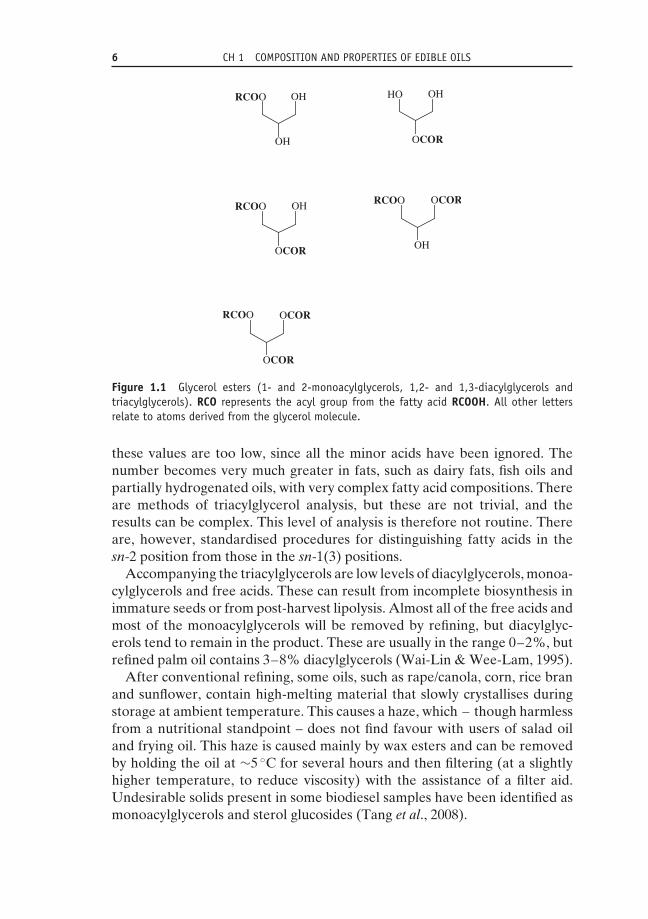
Figure 1.1 Glycerol esters (1- and 2-monoacylglycerols, 1,2- and 1,3-diacylglycerols andtriacylglycerols). RCO represents the acyl group from the fatty acid RCOOH. All other lettersrelate to atoms derived from the glycerol molecule.
these values are too low, since all the minor acids have been ignored. Thenumber becomes very much greater in fats, such as dairy fats, fish oils andpartially hydrogenated oils, with very complex fatty acid compositions. Thereare methods of triacylglycerol analysis, but these are not trivial, and theresults can be complex. This level of analysis is therefore not routine. Thereare, however, standardised procedures for distinguishing fatty acids in thesn-2 position from those in the sn-1(3) positions.
Accompanying the triacylglycerols are low levels of diacylglycerols, monoa-cylglycerols and free acids. These can result from incomplete biosynthesis inimmature seeds or from post-harvest lipolysis. Almost all of the free acids andmost of the monoacylglycerols will be removed by refining, but diacylglyc-erols tend to remain in the product. These are usually in the range 0–2%, butrefined palm oil contains 3–8% diacylglycerols (Wai-Lin & Wee-Lam, 1995).
After conventional refining, some oils, such as rape/canola, corn, rice branand sunflower, contain high-melting material that slowly crystallises duringstorage at ambient temperature. This causes a haze, which – though harmlessfrom a nutritional standpoint – does not find favour with users of salad oiland frying oil. This haze is caused mainly by wax esters and can be removedby holding the oil at ∼5 ◦C for several hours and then filtering (at a slightlyhigher temperature, to reduce viscosity) with the assistance of a filter aid.Undesirable solids present in some biodiesel samples have been identified asmonoacylglycerols and sterol glucosides (Tang et al., 2008).
1.2 COMPONENTS OF NATURAL FATS 7
1.2.2 PhospholipidsCrude oils generally contain phospholipids, which are removed during refiningat the degumming stage (Chapter 4). The valuable crude product contain-ing phospholipids and other lipid molecules is termed ‘lecithin’. It is thebasis of the phospholipid industry, and phospholipids are used extensivelyin food products, animal feed and industrial products; their uses are basedmainly on their amphiphilic properties (i.e. different parts of the moleculeshow lipophilic and hydrophilic properties). The major components (phos-phatidylcholines, phosphatidylethanolamines and phosphatidylinositols) areaccompanied by smaller proportions of other phospholipids (Figure 1.2).Soybean oil, rapeseed oil and sunflower seed oil contain 1.5–2.5%, ≤2.5%and ∼1% phospholipids, respectively. Soybean oil is the major source ofcommercial lecithin, and this raises a problem in that most soybean oil nowcomes from genetically modified sources. Those who want to avoid GMproducts must either find identity-preserved soybean lecithin or use sun-flower lecithin from non-GM seeds. The typical composition of a commercialdeoiled soybean lecithin is 81% phospholipids (mainly PCs, PEs and PIs),10% glycolipids and 6% carbohydrates (Gunstone, 2008). Palm oil containslittle or no phospholipid.
1.2.3 SterolsMost vegetable oils contain 1000–5000 ppm (1–5 g/kg) of sterols, partly asfree sterols and partly as esterified sterols. Higher levels are present inrapeseed oil (5–11 g/kg, mean ∼7.5 g/kg) and in corn oil (8–22 g/kg, mean14 g/kg). β-sitosterol (Figure 1.3) is generally the major phytosterol (50–80%of total sterol), with campesterol, stigmasterol and �5-avenasterol frequentlyattaining significant levels (Tables 1.5 and 1.6). Brassicasterol is virtuallyabsent from the major seed oils, apart from rapeseed oil, in which it makes up10% of total sterol. Kochhar (1983) reviewed sterol composition and sterolcontent in edible vegetable oils and the changes that take place in theseas a result of processing (Section 1.6). Verleyen et al. (2002a, 2002b) havedescribed an analytical procedure by which to measure free sterols and sterolesters and have examined the changes that occur during refining. Cholesterol(Figure 1.3) is considered to be a zoosterol and is not present in plant systemsat a significant level. The normal value of 20–50 ppm in vegetable oils is muchlower than the levels reported for animal fats (up to 1000 ppm), fish oils (upto 7000 ppm), dairy fats (2000–3000 ppm) and egg yolk (12 500 ppm).
Phytosterol (plant sterol) esters are now being added to spreads at sig-nificant levels up to 10% because they are considered to reduce cholesterollevels (Sato et al., 2003). These phytosterols are recovered during wood

8 CH 1 COMPOSITION AND PROPERTIES OF EDIBLE OILS
phosphatidic acids (PAs)
phosphatidylcholines (PCs)
phosphatidylethanolamines (PEs)
phosphatidylinosititols
HO
O P
O
O−
O
O
O
R
X
O
O
O P
O
O−
OH
R1
O
O
R2
ON
O
O
O P
O
O−
R1
O
O
R2 +
ONH3
O
O
O P
O
O−
R1
O
O
R2 +
OH OHOH
OHHO
O
O
O
O P
O
O−
R1
O
O
R2
O
O
O
O
O
O
O−
OP
HN+
2-lysophospholipids:LPC, X = choline;LPE, X = ethanolamine
Figure 1.2 Structures of selected phospholipids (PAs, PCs, PEs, PIs, lysoPLs). These arecorrectly named in the plural because natural products are mixtures of compounds whichvary in the nature of the acyl groups R1CO and R2CO. The final structure is an alternativerepresentation of a PC containing palmitic acid and linoleic acid. These molecules (apart fromphosphatidic acid) contain four ester bonds. On complete hydrolysis they furnish fatty acids,glycerol, phosphoric acid and a hydroxy compound (choline etc.). A series of phospholipaseswhich catalyse selective hydrolysis (lipolysis) of these ester groups exists.Source: Most of these structures have been taken from ‘‘Lipid Glossary 2’’ (The Oily Press, 2000)which can be downloaded free via The Oily Press website by permission of the authors and thepublisher.

1.2 COMPONENTS OF NATURAL FATS 9
HO
HO
Figure 1.3 Cholesterol (top) and sitosterol (bottom).
Table 1.5 Major sterols (campesterol, stigmasterol and β-sitosterol) in vegetable oils aspercentage of total sterols.
Total sterols (mg/kg) Camp Stig β-sito
Palm 300–700 19–27 8–14 50–62Rapea 4500–11300 25–39 0–1 45–58Soybean 1800–4500 16–24 15–19 47–60Sunflower 2400–5000 6–13 6–13 50–70
aRape also contains brassicasterol 5–13% (see Table 1.6).Source: Codex Standard for Named Vegetable Oils, Codex-Stan 210–1999 (adopted 1999, revised 2001,amendments 2003, 2005), Table 3 (available from www.codexalimentarius.org).
processing or are obtained from soybean deodoriser distillate. During high-temperature deodorisation (see Chapter 5), the following are removed inthe distillate: aldehydes, ketones and other short-chain compounds resultingfrom oxidation, tocopherols (vitamin E), sterols, carotene degradation prod-ucts, nitrosamines, residual extraction solvent, organochlorine pesticides andvolatile sulfur compounds (Kao et al., 1998; Torres et al., 2009).
1.2.4 Tocols and other phenolic compoundsTocol extracts are mixtures of up to eight compounds. There are fourtocopherols with a saturated, branched, polyisoprenoid C16 side chain and

10 CH 1 COMPOSITION AND PROPERTIES OF EDIBLE OILS
Table 1.6 Content (mg/100 g) of major esterified and free sterols in crude and refinedvegetable oils.
Esterified sterols Free sterols Total sterols
sum Cp Sg Si Av sum Cp Sg Si Av sum Cp Sg Si Av
Crude oilsPalm 25 5 2 17 – 51 10 5 36 – 79 20 7 52 –Soya 59 6 5 40 9 255 63 55 137 – 327 71 61 184 10Rape 475 193 – 257 26a 336 97 – 171 68a 824 293 – 420 111a
SunRefined oilsPalm 28 6 3 17 2 29 6 4 18 – 60 14 7 36 3Soya 88 11 9 58 10 193 39 40 113 – 267 47 48 159 12Rape 485 191 – 255 39a 278 93 – 158 26a 767 300 – 390 77a
Sun 124 13 4 81 26 192 19 22 138 12 330 36 27 225 42
aThese numbers in rapeseed oil relate to the content of brassicasterol.Cp, campesterol; Sg, stigmasterol; Si, β-sitosterol; Av, �5-avenasterol.Source: Adapted from Verleyen 2002a and 2002b.
OR
R
RHO
5
7 8
Figure 1.4 Tocopherols and tocotrienols. Tocopherols have a saturated C16 side chain,tocotrienols have double bonds at the three positions indicated by the arrows. R=H or CH3.α = 5,7,8-trimethyltocol, β = 5,8-dimethyltocol, γ = 7,8-dimethyltocol, δ = 8-methyltocol.
four tocotrienols with three double bonds in the side chain (Figure 1.4). Thetocotrienols, though significant in palm oil and in rice bran oil, are less commonthan the tocopherols, and less is known about their biological properties.The four tocopherols differ in the number of methyl groups attached tothe heterocyclic moiety (chroman). They are designated α (5,7,8-trimethyl),β (5,7-dimethyl), γ (7,8-dimethyl) and δ (8-methyl). These compounds aresometimes incorrectly described as isomers, but this is true only for the β andγ compounds.
The tocols have two valuable properties: they show vitamin E activityand they are powerful antioxidants (Elmadfa & Wagner, 1997). These twoproperties are not identical. For vitamin E activity, the order is α (1.0),β (0.5), γ (0.1), δ (0.03), with total activity expressed in α-tocopherol units.For antioxidants, this order is reversed. Some typical levels are presentedin Table 1.7. Among the readily available oils, palm and sunflower (as wellas walnut and wheatgerm) are good sources of vitamin E because of the

1.2 COMPONENTS OF NATURAL FATS 11
Table 1.7 Tocols in the major vegetable oils (mg/kg equivalent ppm).
Vegetableoil
Total(mg/kg)
Tocopherols Tocotrienols
α β γ δ α γ δ
Palm 150–1500 4–193 0–234 0–526 0–123 4–336 14–710 0–377Rape 430–2680 100–386 0–140 189–753 0–22 ND ND NDSoybean 600–3370 9–352 0–36 89–2307 154–932 0-69 0-103 NDSunflower 440–1520 409–935 0–45 0–34 0–7 ND ND NDWheatgerm 2540 1210 650 240 250 20 170PFAD 744–8192 (21%) – – – (16%) (39%) (24%)
Deodoriser distillates are enriched in tocols but have variable composition. SBDD is reported to contain 19and 11% tocopherols (mainly gamma and delta) in two reports, and PFAD typically has the compositionshown in the table.Further information on the four major oils is available in appropriate chapters of Gunstone (2011) and inYang (2003).Source: Codex Standard for Named Vegetable Oils, Codex-Stan 210–1999 (adopted 1999, revised 2001,amendments 2003, 2005), Table 4 (available from www.codexalimentarius.org, last accessed 8 January2013).
Table 1.8 Levels (ppm, equivalent to mg/kg)of the four tocopherols in crude rapeseed, palm,soybean and sunflower oils.
Oil α β γ δ
Rapeseed 175 0 415 10Palm 190 0 0 0Soybean 120 10 610 190Sunflower 610 10 30 10
Source: Adapted from Warner (2007).
high levels of the α compound, whereas soybean tocopherols are effectiveantioxidants due to their high levels of γ and δ compounds (Evans et al.,2002; Wagner & Isnardy, 2006; Warner, 2007; Warner et al., 2008). Thetocopherols are recovered from refinery byproducts such as palm fatty aciddistillate (PFAD) and soybean deodoriser distillate (SBDD) (Table 1.8). Thecompositions of PFAD and SBDD are somewhat variable depending on therefining conditions employed.
Netscher reported in 1999 that production of vitamin E was about 20 000tonnes. This included synthetic vitamin E (90%) – a mixture of eight racemicforms – made from trimethylhydroquinone and (all-rac-)-phytol and naturalvitamin E (10%) principally from soybean. The latter product is an excellentantioxidant but its vitamin E activity is limited because of the low proportionof the α compound. This can be raised by a per-methylation reaction, which

12 CH 1 COMPOSITION AND PROPERTIES OF EDIBLE OILS
converts the mono- and dimethyl compounds to the trimethyl derivative.These products, whether natural or synthetic, are used in the animal feed,food and pharmaceutical industries.
Crude palm oil contains up to 800 ppm of tocols, of which α-tocopherolrepresents 22% and β-, γ- and δ-tocotrienol represent 20, 46 and 12%,respectively. About 70% of this mixture remains in the oil after refining,with the remainder present in PFAD at a level 5–10 times higher than inthe original oil. This is used as a source of Palm ViteeTM, which is 95%tocols rich in tocotrienol (>60%) (Basiron, 2005). Tocols in other oils havebeen discussed by Clark (1996), Ghosh & Bhattacharyya (1996) and Walshet al. (1998).
Natural tocopherol mixtures are usually used as antioxidants at levels up to500 ppm (along with ascorbyl palmitate, which extends antioxidant activity).At higher levels (>1000 ppm), α-tocopherol acts as a prooxidant. Sincevegetable oils generally contain tocols at 200–800 ppm, further additions showonly a limited effect. Evans et al. (2002) have discussed the optimal tocopherolblend for inhibiting soybean oil oxidation. The tocols are themselves verysensitive to oxidation and are more stable in an esterified form when the all-important hydroxyl (phenolic) group is not free. However, such compoundsdo not show antioxidant activity until they have been hydrolysed in vivo tothe free phenolic form.
Many plant sources of lipids contain phenolic compounds other than thetocols. Some of these are water-soluble and are not extracted with thenonpolar lipids. However, they may be present in oils that are obtained bypressing rather than by hexane extraction. This holds for olive oil, whichcontains a wide range of phenolic compounds (Boskou, 2011), and for thegrowing range of cold-pressed oils. Sesame and rice bran oils are knownfor their high oxidative stability. They contain phenolic compounds whichact as powerful antioxidants, including the sesamin lignans in sesame oiland the oryzanols (esters of ferulic acid – 3-methoxy 4-hydroxy cinnamicacid – MeO(HO)C6H3CH=CHCOOH) in ricebran oil (Kochhar, 2011).
1.2.5 ChlorophyllChlorophyll and its magnesium-free derivative (phaeophytin) are not wantedin refined oils because they produce an undesirable green hue and act assensitisers for photooxidation (Section 1.5.2). No general listing of chloro-phyll/phaeophytin levels has been discovered, but the following informationhas been gleaned from a range of sources (the levels cited for chlorophyllinclude phaeophytin):
• Olive oil: chlorophyll pigment levels vary with the maturity of the olive andthe method of extraction. Unrefined oil contains 10–30 ppm chlorophyll.

1.2 COMPONENTS OF NATURAL FATS 13
• Canola oil: levels of chlorophyll in crude oil (5–35 ppm) are much reduced(<50 ppb) by alkali refining and bleaching (Przybylski, 2011).
• Soybean oil: low levels of chlorophyll in crude oil (1.0–1.5 ppm) are reducedto about 15 ppb after refining.
• Sunflower oil: crude oil contains 200–500 ppb chlorophyll, but in refinedoil this is reduced to <30 ppb.
• Palm oil: crude palm oil contains 250–1800 ppb chlorophyll (mean 900 ppb,SD 100). The level falls with increasing maturity of the palm fruit.
1.2.6 HydrocarbonsThough hydrocarbons are minor components of oils and fats, they areof dietary and legislative interest. They include alkanes, alkenes (such assqualene and carotenes) and polycyclic aromatic hydrocarbons (PAHs).
1.2.6.1 Alkanes
Many studies of alkanes ignore the more volatile compounds (up to C12 andincluding C6, used as an extraction solvent) because of analytical difficultiesarising from their volatility. They are not likely to be significant in refinedoils that have been submitted to high-temperature deodorisation. Levels ofC13 –C33 alkanes in crude oils are usually between 40 and 100 mg/kg (ppm),with lower levels for refined oils. Typical values, in ppb, reported by McGillet al. (1993) are 30–100 for olive, 100–170 for sunflower, 25–35 for cornand 25–35 for groundnut oil in samples purchased from retail outlets. Thereis a preference for odd-chain molecules, as illustrated in Table 1.9. Thevariation between different oils can be used to fingerprint them, and theconsistency in the proportion of different alkanes – if not of the total levelspresent – suggests that they may be endogenous and not exogenous artefacts.Kao et al. (1998) have described some C8 –C18 unsaturated hydrocarbonspresent in deodoriser distillate, but these are probably thermal-decompositionproducts of glycerol esters.
1.2.6.2 Squalene
Squalene (C30H50, Figure 1.5) is a highly unsaturated open-chain triterpeneused in the cosmetics industry after hydrogenation to squalane (C30H62).The most abundant source of squalene is the liver oil of the deep-seadogfish (Squalus acanthus, hence the name ‘squalene’) and of some othermarine species. Vegetable sources of potential interest include olive oil andamaranthus oil. Squalene levels of 100–1200 mg/100 ml of oil have beenreported in olive oil, with most samples containing 200–500 g/100 ml (deLeonardis et al., 1998). This rises to 200–500 mg/100 ml in the deodoriserdistillate (Bondioli et al., 1993). Amaranthus contains 6–8% squalene and this

14 CH 1 COMPOSITION AND PROPERTIES OF EDIBLE OILS
Table 1.9 Odd-chain alkanes in selected seed oils (mg/kg, ppm).
Alkane(carbon atoms)
Sunflower Olive(extra virgin)
Sesame
23 <1 19 <125 2 18 127 11 16 629 50 12 1831 48 9 1433 4 6 7
23–33 115 80 46Total alkanesa 105–166 (5) 28–99 (6) 22–82 (4)
aNumber in brackets = number of samples examined.
Figure 1.5 Squalene (C30H50).
concentration can be raised 10-fold after short-path high-vacuum distillation(Sun et al., 1997).
1.2.6.3 CarotenesCarotenes are minor components of most vegetable oils but occur to a greaterdegree in palm oil. These molecules contain a long chain of conjugatedunsaturation and are yellow/orange in colour (Figure 1.6). Crude palmoil normally contains 500–700 ppm carotenes. These are mainly α-carotene(24–42% of total carotenes) and β-carotene (50–60%), with low levels ofseveral other carotenes. Carotenes are also present in palm leaves and in thepressed fibre that remains when oil has been expressed from palm fruits. Thisfibre still contains 5–6% of oil that is very rich in carotenes (4000–6000 ppm).When palm oil is refined, bleached and deodorised in the normal way,the carotenes are completely destroyed. Carotenes are a biological sourceof vitamin A, act as powerful antioxidants against both autoxidation andphotooxygenation (Section 1.5.2) and show anticancer activity. Attemptshave therefore been made to retain these valuable materials in refined palmoil or to recover them in concentrated form.
Products such as red palm oil and NutroleinTM are palm oils or palmoleins that retain most of the original carotene obtained by carrying outdeodorisation at temperatures below 150 ◦C. Carotenes can be recoveredfrom palm methyl esters, prepared by methanolysis of palm oil and producedin large quantities for biodiesel and other purposes. This is achieved by

1.2 COMPONENTS OF NATURAL FATS 15
Figure 1.6 β-carotene (C40H56). Other carotenes vary in the nature of the cyclic end groups.
chromatography in an open column or by molecular distillation. The latteroption gives a carotene concentrate (8%) that can be further purified (>90%)by chromatography (Baharin et al., 1998; Ooi et al., 1994; Yanishlieva et al.,1998). The various methods for obtaining carotene from palm oil have beenreviewed by Thyrion (1999).
Muller (1995) has reported the daily intake of individual carotenes andYanishlieva and coworkers (1998) have reviewed the role of β-carotene asan antioxidant. Stanley (1999) has described some of the conflicting resultsconcerning the biopotency of carotene supplied as a concentrate rather thanas part of a food.
1.2.6.4 Polycyclic aromatic hydrocarbonsPAHs are present at levels up to about 150 μg/kg (ppb) in a number of crudevegetable oils, but less after refining (<80 ppb). They are removed to a smallextent during bleaching and somewhat more during deodorisation. This isparticularly the case for the more volatile tri- and tetracyclic compounds. Thepentacyclic and other less volatile compounds are best removed with activatedcharcoal, which can be added to earth during bleaching. These values do nothold for crude coconut oil when the copra is dried with combustion gases,where values around 3000 ppb are normally recorded. Normal values areobtained after charcoal treatment (Larsson et al., 1987). In Finland, Hopiaand coworkers (1986) examined margarines, butters and vegetable oils fortheir levels of 38 different PAHs. Apart from a sample of crude coconutoil (4600 ppb), they gave values between 1 and 90 ppb. These compoundsprobably result from PAHs present in the atmosphere as a result of human-induced combustion of gas, coal or oil. Gertz & Kogelheide (1994) reportedon PAHs in 40 native and refined vegetable oils. Extracted oils may containpesticides resulting from agricultural processes, but these are usually removedduring deodorisation.
Gossypol is a toxic hexaphenolic C40 compound present in cotton bollcavities. When the seed is extracted, the gossypol adheres to the protein mealand only a small proportion remains in the crude oil. Residual gossypol givesa red-brown colour to crude cottonseed oil but is largely removed duringchemical refining and is present only at safe levels of 1–5 ppm in the final

16 CH 1 COMPOSITION AND PROPERTIES OF EDIBLE OILS
product. Kenar (2006) has reviewed the reaction chemistry of gossypol andits derivatives.
1.2.6.5 Contaminants and specificationsA typical specification includes the following impurities and limits for refinedoils based on customer requirements, industry standards and EU legisla-tion: taste and colour (bland), moisture (max. 0.05%), phosphorus (max.5 ppm), insolubles (not visible), free fatty acids (max. 0.1%), peroxides (max.1 meq/kg), iron (max. 0.5 ppm), copper (0.05 ppm), lead (max. 0.01 ppm), hex-ane (max. 5 ppm), benz(a)pyrene (max. 2 ppb), pesticides (maximum residuelevel in seeds, limit of detection in oils), dioxins (0.75 pg), aflatoxins (2 ppbaflatoxin B1, 4 ppb aflatoxin B1, B2, G1, G2), mineral oil (LOD) and residuesof previous cargoes (complete removal).
1.3 Fatty acid compositionThe food uses of lipids depend on their physical, chemical and nutritionalproperties, which are linked to their fatty acid and triacylglycerol composition.The latter is important but can be quite complex and for most practicalpurposes lipids are discussed in terms of their fatty acid composition. Typicalvalues for the fatty acid composition of a range of oils and fats are presented inTable 1.10. These will not be considered in detail, but a few general points willbe made. Figures cited in these tables must be considered merely as typicalvalues. Debruyne (2007), Wilkes (2008) and Watkins (2009) have describedsome of the new varieties being investigated.
Coconut and palm kernel oils (Table 1.11) are typical lauric oils and differfrom most of the other vegetable oils. They are important in both the foodand the oleochemical industries and are characterised by high levels of lauricacid (12 : 0), significant levels of myristic acid (14 : 0) and useful levels ofoctanoic (8 : 0) and decanoic acids (10 : 0). The lauric oils are rich in saturatedacids (80–90%) and contain very little unsaturated acid. Palm kernel oil isone of two products from the oil palm and must not be confused with the verydifferent palm oil, which is the major product from this tree.
Most vegetable oils contain palmitic, oleic and linoleic (Table 1.10). Thewriter has calculated that the world’s commodity oils in 2004/05 – both veg-etable and animal fats – contained 83% of these three acids (Gunstone,2005). Calculations were based on the fatty acid composition of each oiland on the level of production in that year. Palmitic as the major satu-rated acid reaches significant levels in palm oil (46%) and in cottonseed oil(27%). Some oils are rich in oleic acid (olive, canola), some in linoleic acid(corn, cottonseed, linola, soybean and sunflower) and some in both acids(groundnut). Seed breeders have produced oleic-rich varieties of many of

1.3 FATTY ACID COMPOSITION 17
Table 1.10 Typical fatty acid compositions (%wt) of selected oils and fats.
14 : 0 16 : 0 16 : 1 18 : 0 18 : 1 18 : 2 18 : 3
Cocoa butter – 26 – 34 35 – –Corn – 13 – 3 31 52 1Cottonseed – 27 – 2 18 51 trGroundnut – 13 – 3 38 41 trLinola – 6 – 3 16 72 2Linseed – 6 – 3 17 14 60Olive – 10 – 2 78 7 1Palm – 46 – 4 40 10 trPalm olein – 40 – 4 43 11 trRapea – 3 – 1 16 14 10Rapeb – 4 – 2 56 26 10Soybean – 11 – 4 22 53 8Sunflower – 6 – 5 20 60 trSunolac – 4 – 5 81 8 trNusun – 4 – 5 65 26 –Butterd 12 26 3 11 28 2 1Lard 2 27 4 11 44 11 –Beef tallow 3 27 11 7 48 2 –Mutton tallow 6 27 2 32 31 2 –
aHigh erucic (also 20 : 1 6% and 22 : 1 55%).bLow erucic.cHigh oleic sunflower.dAlso 4 : 0 (3%), 6 : 0 (2%), 8 : 0 (1%), 10 : 0 (3%) and 12 : 0 (4%).tr, trace (<1%).
Table 1.11 Typical fatty acid compositions (%wt) of lauric oils.
8 : 0 10 : 0 12 : 0 14 : 0 16 : 0 18 : 0 18 : 1 18 : 2
Coconut 8 7 48 16 9 2 7 2Palm kernel 3 4 45 18 9 2 15 3
these oils. For example, commodity sunflower oil normally contains about20% oleic acid and 60% linoleic, but two other varieties are now commer-cially available with higher levels of oleic acid and lower levels of linoleicacid. NuSun contains about 65% oleic acid and high-oleic sunflower is at least80% oleic acid. These have been produced by conventional seed breedingprocedures and are not genetically modified products (Anon, 1998; Watkins,2009; Wilkes, 2008).
Linolenic acid (18 : 3) is the major acid in linseed oil (60%) and is thebasis for most of the industrial uses of this oil. ‘Linola’ is the name givento a chemically induced mutant with low levels of linolenic acid and high

18 CH 1 COMPOSITION AND PROPERTIES OF EDIBLE OILS
levels of linoleic acid (Table 1.10). Linolenic acid is also present in soybeanoil (8%) and in rapeseed oil (10%). There is some ambivalence about thisacid. Its presence promotes undesirable oxidation and foods containing ithave reduced shelf life. This problem has been overcome traditionally by avery light hydrogenation (brush hydrogenation), which halves the level oflinolenic acid. More recently, new varieties of these oils have been developedwith lower levels of linolenic acid – some of them by genetic modification.
Cocoa butter, the lipid component in chocolate, is an unusual vegetablefat with saturated (∼60%) and monoene (∼35%) acids in such proportionsthat its triacylglycerols are mainly of the SOS type (S = saturated, O = oleic).These are responsible for the characteristic melting behaviour of this fat,which is so important in chocolate (Timms, 2003). Other vegetable fats withsimilar compositions and similar melting characteristics are designated cocoabutter equivalents (CBEs).
These comments hold for the major vegetable oils and fats and also for mostof the minor seed oils, but some other oilseeds illustrate the rich diversity ofplants in their ability to generate unusual fatty acids, sometimes at very highlevels. Examples include castor oil (90% ricinoleic acid – 12-hydroxyoleicacid), coriander oil (80% petroselinic acid – 6-octadecenoic acid), Vernoniagalamensis seed oil (75% vernolic acid – cis-12,13-epoxyoleic acid) and theseed oil of Picramnia sow (95% tariric acid – 6-octadecynoic acid).
The major animal fats are more saturated than vegetable oils and containonly low levels of PUFAs. They generally consist of 40–60% saturated acidsand 30–60% monounsaturated acids. Butter has acids with a wide range ofchain lengths (4–18 carbon atoms) but, like the animal depot fats, it is rich insaturated and monoene acids and low in polyunsaturates. Because of the largenumber of fatty acids in milk fat, differing in chain length and unsaturation,the triacylglycerol composition is much more complex than that of mostvegetable oils. This makes fractionation of anhydrous milk fat (AMF), basedon only slightly different properties among the many triacylglycerols, verydifficult. Some indication of triacylglycerol complexity was given in a paper byRobinson & MacGibbon (1998). Using silver ion thin-layer chromatography(TLC) and reversed-phase high-performance liquid chromatography (RP-HPLC) they isolated 61 fractions, each of which contained one to fourmajor triacylglycerol components. Some of the difficulties of fractionationwere discussed by Bhaskar and coworkers (1998) in a paper comparing thephysical and chemical properties of milk fat fractions obtained by commercialmelt crystallisation and supercritical carbon dioxide extraction.
Fish oils are characterised by the wide range of acids present and, par-ticularly, by the highly unsaturated members. Saturated (14 : 0 and 16 : 0),monoenoic (16 : 1, 18 : 1, 20 : 1 and 22 : 1) and omega-3 polyenoic acids (eicos-apentaenoic acid, 20 : 5 and docosahexaenoic acid, 22 : 6) are frequently majorcomponents, and fish oils are valued for the latter.

1.4 PHYSICAL PROPERTIES 19
1.4 Physical properties1.4.1 Polymorphism, crystal structure and melting pointImportant physical properties relevant to this book are polymorphism, crystalstructure and melting point, which combine in the melting behaviour oflipid mixtures.
In the solid state, long-chain compounds frequently exist in more than onecrystalline form and may consequently have more than one melting point.This property of polymorphism is of both scientific and technical interest.Understanding this phenomenon is essential for the satisfactory blending andtempering of fat-containing materials, such as baking and confectionery fats,which must attain a particular physical appearance during preparation andmaintain it during storage. Problems of graininess in spreads and of bloom inchocolate, for example, are both related to polymorphic changes. The experi-mental methods used most extensively to examine melting and crystallisationinvolve dilatometry, low-resolution pulsed 1H NMR spectroscopy, differen-tial scanning calorimetry (DSC), infrared spectroscopy and X-ray diffraction(Larsson et al., 2006; Timms, 2003).
Alkanoic acids exist in three polymorphic forms, designated A, B and C foracids with an even number of carbon atoms. Form C has the highest meltingpoint and is physically the most stable. It is obtained by crystallisation fromthe melt or from polar solvents. Crystallisation from nonpolar solvents givesform A or forms B and C.
For the purpose of this book, the melting point of triacylglycerols ismore important. It has long been known that fats show multiple meltingpoints. As far back as 1853, glycerol tristearate was known to have threemelting points (52, 64 and 70 ◦C). When the melt of a simple triacylglycerolis cooled quickly, it solidifies in the form with lowest melting point (α)with perpendicular alkyl chains in its unit cell (angle of tilt is 90◦). Whenheated slowly, this melts, and held just above the melting point, it willresolidify in the β′ crystalline form. In the same way, a more stable β formcan be obtained from the β′ form. The β form has the highest meltingpoint and is obtained directly from solvent by crystallisation. The β′ and β
forms have tilted alkyl chains, which permit more efficient packing of thetriacylglycerol molecule in the crystal lattice. Glycerol esters with only onetype of acyl chain have been thoroughly studied. The results have provideduseful guidance, but such molecules are not generally significant componentsof natural fats (except perhaps after complete hydrogenation). With mixedsaturated triacylglycerols such as PStP (P = palmitic, St = stearic), the β formis only obtained with difficulty, and such compounds usually exist in theirβ′ form. Among unsaturated triacylglycerols, symmetrical compounds (SUSand USU, where S = saturated and U = unsaturated acyl chains) have higher

20 CH 1 COMPOSITION AND PROPERTIES OF EDIBLE OILS
melting β forms (more stable) but the unsymmetrical compounds (USS andUUS) have stable β′ forms.
Crystallisation occurs in two stages: nucleation and growth. A crystalnucleus is the smallest crystal that can exist in solution and is dependenton concentration and temperature. Spontaneous (homogeneous) nucleationrarely occurs in fats. Instead, heterogeneous nucleation occurs on solidparticles (dust etc.) or on the walls of the container. Once crystals are formed,fragments may drop off and either redissolve or form nuclei for furthercrystals. The latter is not desirable in fat crystallisation, so agitation duringfractionation should be kept to the minimum required to facilitate heattransfer (see Chapter 6).
Nucleation rates for the different polymorphs are in the order α > β′ > β sothat α and β′ are more readily formed in the first instance, even though the β
polymorph is the most stable and favoured thermodynamically. Crystal nucleigrow by incorporation of other molecules from the adjacent liquid layer, at arate depending on the amount of supercooling and the viscosity of the melt(Gibon, 2006; Lawler & Dimock, 2002; Mori, 1988; Timms, 2005).
In the production of spreads and shortenings, the β′ crystalline form ispreferred over the β form. β′ crystals are relatively small and can incorporatea large amount of liquid. This gives the product a glossy surface and a smoothtexture. β crystals, on the other hand, though initially small, grow into needle-like agglomerates. These are less able to incorporate liquid and produce agrainy texture. Spreads and shortenings made from rape/canola, sunfloweror partially hydrogenated soybean oil generally develop crystals. This can beinhibited or prevented by incorporation of some palm oil or palm olein, whichstabilises the crystals in the β′ form. These changes in crystallisation patternare linked with the larger amount of palmitic acid in the palm products.Glycerol esters with C16 and C18 acyl chains are more likely to be stable inthe β′ form than glycerol esters with three C18 chains.
Cocoa butter is particularly rich in three 2-oleo-1,3-disaturated glycerolesters, namely POP, POSt and StOSt. The solid fat has been identified insix crystalline forms, designated I–VI (the melting points and the nature ofthe double/triple chain lengths are indicated in Table 1.12). Of these, form V(β2) is preferred for chocolate. This crystalline form gives good demouldingcharacteristics and has a stable gloss and a favourable snap at room tem-perature. Two procedures have been employed to promote the formation ofthis particular crystalline form. The most widely used is tempering; that is,putting molten chocolate through a series of cooling and heating processes.This optimises the production of the appropriate polymorph. An alternativeprocedure requires seeding of the molten chocolate with cocoa butter alreadyprepared in form V (β2) or VI (β1), but this method is restricted by thedifficulty of obtaining adequate supplies of these crystalline forms. The syn-thetic glycerol ester, 2-oleo-1.3-dibehenin (BOB, O = 18 : 1, B = 22 : 0), may

1.4 PHYSICAL PROPERTIES 21
Table 1.12 Polymorphism in cocoa butter.
I II III IV V VI
MP (◦C) 17.3 23.3 25.5 27.3 33.8 36.3Chain length D D D D T T
D, double chain length; T, triple chain length; MP, melting point.
be added to cocoa butter to prevent bloom formation by keeping it in its formV at temperatures above 30 ◦C (Longchampt & Hartel, 2004; Norberg, 2006;Timms, 2003; other relevant references are Gibon, 2006; Martini et al., 2006;and Smith, 2009).
Oils rich in saturated acids may contain high-melting triacylglycerols thatcrystallise from the oil when stored. When this is considered to be undesirable,the oil is subjected to winterisation (see Chapter 6). This process is applied tocottonseed oil and to partially hydrogenated soybean oil.
1.4.2 DensityDensity is very important in the oil trade since fatty oil shipments are sold ona weight basis but measured on a volume basis. Since these two values arerelated by density, it is important to have correct and agreed values for thisunit. Density is not the same for all oils but depends on fatty acid compositionand on minor components, as well as on temperature. An equation takingthese variables into account is based on iodine value (IV), saponificationvalue (SV) and temperature (Pantzaris, 1985):
d = 0.8543 + 0.000308 (SV) + 0.000157 (IV)–0.000681t (1.1)
where d is apparent density (g/ml or kg/l) and t is temperature.Density can be defined in various ways and the correct form must be used
when relating volume to weight:
• Density (absolute density or density in vacuum) is the ‘mass in vacuumof a volume of oil at t ◦C ÷ volume of the oil at the same temperature’,expressed in g/ml or kg/l.
• Apparent density (density in air, weight-by-volume or litre-mass) is the‘mass in air of a volume of oil at t ◦C ÷ volume of the oil at the sametemperature’, expressed in g/ml or kg/l.
• Relative density (specific gravity, density in relation to water) is the ‘massin air of a given volume of oil at t1
◦C ÷ mass in air of same volume ofwater at t2
◦C’. This is a ratio without units. It is important to note thattwo temperatures are involved and the value is meaningless unless both

22 CH 1 COMPOSITION AND PROPERTIES OF EDIBLE OILS
figures are cited. Relative density is the value most commonly employedand equations exist to connect these three expressions.
Halvorsen and coworkers (1993) have described a method for estimatingthe density of fatty acids and vegetable oils based on critical volume, criticaltemperature, critical pressure and a modified Racket equation. Some datahave been published by Coupland & McClements (1997), and Topallar andcoworkers (1995) have reported the effect of hydrogenation on the densityand viscosity of sunflower seed oil.
1.4.3 ViscosityViscosity can be reported as kinematic viscosity or dynamic viscosity, withthe two values related through density. The viscosity of a vegetable oildepends on its chemical composition (summarised in its IV and SV) and thetemperature of measurement. Equations have been derived which permitthe calculation of viscosity from a knowledge of these three parameters.They have been developed empirically from observation of a range of oilsat different temperatures and have been reported by Duff & Prasad (1989),Toro-Vazquez & Infante-Guerrero (1993), Rabelo et al. (2000), Azian et al.(2001) and Fasina et al. (2006). Coupland & McClements (1997) and Fisher(1998) have related viscosity with density, refraction, surface tension and otherphysical properties. The relation between temperature and viscosity has beendescribed for coconut oil, palm kernel oil, palm oil and mixtures (Timms,1985), and for several vegetable oils (Noureddini et al., 1992). Changes inviscosity have been used to monitor interesterification (De Filippis et al.,1995) and hydrogenation (Topallar et al., 1995).
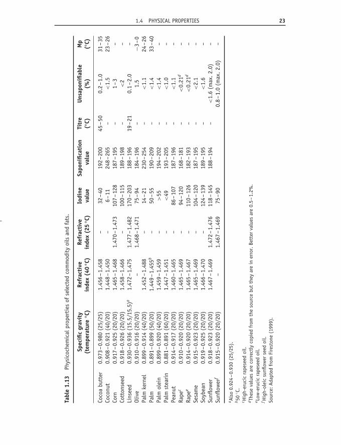
1.4.4 Refractive indexThe refractive index is easily measured using small amounts of material.The refractive index increases with chain length (though not in a linearfashion) and with increasing unsaturation. Geometric isomers differ fromone another and methylene-interrupted polyenes differ from those withconjugated unsaturation. Triacylglycerols have higher values than free acids.Values for commercial oils are given in Table 1.13.
1.4.5 Solubility of gases in oilsA recent discussion (Hilder, 1997) of the solubility of gases in vegetable oilsincluded the data for oxygen, nitrogen and air presented in Tables 1.14 and1.15. When an oil is in contact with air, the dissolved gases will depend on
1.4 PHYSICAL PROPERTIES 23
Tabl
e1.
13Ph
ysic
oche
mic
alpr
oper
ties
ofse
lect
edco
mm
odit
yoi
lsan
dfa
ts.
Spec
ific
grav
ity
(tem
pera
ture
◦ C)
Refr
acti
vein
dex
(40
◦ C)
Refr
acti
vein
dex
(25
◦ C)
Iodi
neva
lue
Sapo
nific
atio
nva
lue
Titr
e(◦
C)U
nsap
onifi
able
(%)
Mp
(◦C)
Coco
abu
tter
0.97
3–0.
980
(25/
25)
1.45
6–1.
458
–32
–40
192–20
045
–50
0.2–1.
031
–35
Coco
nut
0.90
8–0.
921
(40/
20)
1.44
8–1.
450
–6–11
248–26
5–
<1.
523
–26
Corn
0.91
7–0.
925
(20/
20)
1.46
5–1.
468
1.47
0–1.
473
107–12
818
7–19
5–
1–3
–Co
tton
seed
0.91
8–0.
926
(20/
20)
1.45
8–1.
466
–10
0–11
518
9–19
8–
<2
–Li
nsee
d0.
930–0.
936
(15.
5/15
.5)a
1.47
2–1.
475
1.47
7–1.
482
170–20
318
8–19
619
–21
0.1–2.
0–
Oliv
e0.
910–0.
916
(20/
20)
–1.
468–1.
471
75–94
184–19
6–
1.5
−3–0
Palm
kern
el0.
899–0.
914
(40/
20)
1.45
2–1.
488
–14
–21
230–25
4–
<1.
124
–26
Palm
0.89
1–0.
899
(50/
20)
1.44
9–1.
455b
–50
–55
190–20
9–
<1.
433
–40
Palm
olei
n0.
899–0.
920
(40/
20)
1.45
9–1.
459
–>
5519
4–20
2–
<1.
4–
Palm
stea
rin
0.88
1–0.
891
(60/
20)
1.44
7–1.
451
–<
4919
3–20
5–
<1.
0–
Pean
ut0.
914–0.
917
(20/
20)
1.46
0–1.
465
–86
–10
718
7–19
6–
<1.
1–
Rape
c0.
910–0.
920
(20/
20)
1.46
5–1.
469
–94
–12
016
8–18
1–
<0.
21d
–Ra
pee
0.91
4–0.
920
(20/
20)
1.46
5–1.
467
–11
0–12
618
2–19
3–
<0.
21d
–Se
sam
e0.
915–0.
923
(20/
20)
1.46
5–1.
469
–10
4–12
018
7–19
5–
<2.
1–
Soyb
ean
0.91
9–0.
925
(20/
20)
1.46
6–1.
470
–12
4–13
918
9–19
5–
<1.
6–
Sunfl
ower
0.91
8–0.
923
(20/
20)
1.46
7–1.
469
1.47
2–1.
476
118–14
518
8–19
4–
<1.
6(m
ax.
2.0)
–Su
nflow
erf
0.91
5–0.
920
(20/
20)
–1.
467–1.
469
75–90
0.8–1.
0(m
ax.
2.0)
–
a Als
o0.
924–0.
930
(25/
25).
b 50
◦ C.
c Hig
h-er
ucic
rape
seed
oil.
dTh
ese
valu
esar
eco
rrec
tly
copi
edfr
omth
eso
urce
but
they
are
iner
ror.
Bett
erva
lues
are
0.5–1.
2%.
e Low
-eru
cic
rape
seed
oil.
f Hig
h-ol
eic
sunfl
ower
seed
oil.
Sour
ce:Ad
apte
dfr
omFi
rest
one
(199
9).
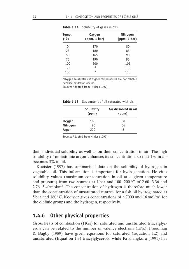
24 CH 1 COMPOSITION AND PROPERTIES OF EDIBLE OILS
Table 1.14 Solubility of gases in oils.
Temp.(◦C)
Oxygen(ppm, 1 bar)
Nitrogen(ppm, 1 bar)
0 170 8025 180 8550 165 9075 190 95100 200 105125 a 110150 a 115
aOxygen solubilities at higher temperatures are not reliablebecause oxidation occurs.Source: Adapted from Hilder (1997).
Table 1.15 Gas content of oil saturated with air.
Solubility(ppm)
Air dissolved in oil(ppm)
Oxygen 180 38Nitrogen 85 66Argon 270 S
Source: Adapted from Hilder (1997).
their individual solubility as well as on their concentration in air. The highsolubility of monatomic argon enhances its concentration, so that 1% in airbecomes 3% in oil.
Koetsier (1997) has summarised data on the solubility of hydrogen invegetable oil. This information is important for hydrogenation. He citessolubility values (maximum concentration in oil at a given temperatureand pressure) from two sources at 1 bar and 100–200 ◦C of 2.60–3.36 and2.76–3.40 mol/m3. The concentration of hydrogen is therefore much lowerthan the concentration of unsaturated centres; for a fish oil hydrogenated at5 bar and 180 ◦C, Koetsier gives concentrations of ∼7000 and 16 mol/m3 forthe olefinic groups and the hydrogen, respectively.
1.4.6 Other physical propertiesGross heats of combustion (HGs) for saturated and unsaturated triacylglyc-erols can be related to the number of valence electrons (ENs). Freedman& Bagby (1989) have given equations for saturated (Equation 1.2) andunsaturated (Equation 1.3) triacylglycerols, while Krisnangkura (1991) has

1.5 CHEMICAL PROPERTIES 25
expressed this relationship in terms of SV and IV (Equation 1.4).
HG = −109.20 + 26.38 EN (1.2)
HG = 115.87 + 25.88 EN (1.3)
HG = 1 896 000/SV − 0.6 IV − 1600 (1.4)
In a useful paper, Coupland & McClements (1997) reported several phys-ical properties (density, viscosity, adiabatic expansion coefficient, thermalconductivity, specific heat, ultrasonic velocity and ultrasonic attenuationcoefficient) for a number of liquid oils (coconut, corn, cottonseed, crambe,grapeseed, groundnut, olive, palm, palm-olein, palm kernel, rape, rice bran,safflower, sesame, soybean and sunflower). Timms (1978) reviewed andsignificantly extended information on the heats of fusion of glycerol esters.He derived an equation for the heat of fusion of mono-acid triacylglycerolsin the β polymorph form and showed how this could be adapted to calculatethe heat of fusion of most glycerol esters of commercial interest. Chumpitazet al. (1999) have recently reported the surface tensions of four fatty acids(lauric, myristic, palmitic and oleic) and two triacylglycerols (tricaprylinand tripalmitin) over a range of temperatures. These data are importantfor processes involving gas–liquid contact, such as distillation and strippingcolumns, deodorisers, reactors and equipment for physical refining. Fisher(2000) has presented equations correlating several properties of n-fatty acidsand derivatives with chain length.
Some useful data in this section (Table 1.13) have been taken from theAOCS publication Physical and Chemical Characteristics of Oils, Fats, andWaxes (Firestone, 1999).
1.5 Chemical properties1.5.1 HydrogenationHydrogenation and, more importantly, partial hydrogenation of some of theunsaturated centres in a liquid oil to convert it into a solid or semisolid fatis an important procedure in making them usable as spreads. However, withcurrent concern about trans acids, this process has become less useful. Thetopic is discussed in Chapter 6 and will not be pursued further in this chapter.
1.5.2 OxidationPart of the refining process (see Chapter 5) involves removal of oxidationproducts, with their undesirable flavour and aroma, after which furtheroxidation must be inhibited as efficiently as possible during processing of oils

26 CH 1 COMPOSITION AND PROPERTIES OF EDIBLE OILS
and fats, food processing and storage up to the moment of consumption. Theword ‘inhibited’ is used because it is virtually impossible to prevent oxidation.It is therefore important to understand this reaction in order that the lipid isalways handled under appropriate conditions. It is only possible to give a briefaccount of this topic in the present volume. The best, fullest and most relevantaccounts are to be found in two recent books by Frankel (2005, 2007); thetopic is also fully reviewed in Food Lipids, edited by Akoh & Min (2008).
Non-enzymatic oxidation occurs by two routes, and it is necessary toprotect against both. Lipid oxidation is accelerated by metals, light, heat andseveral initiators (prooxidants) and can be inhibited by avoiding prooxidantsand including antioxidants. The primary products are allylic hydroperoxides.Double bonds remain, though they may have changed configurations andposition in the fatty acid chain. These compounds are not directly responsiblefor the undesirable flavour and aroma associated with rancid fat, but theyare unstable molecules which readily undergo a series of secondary reactions,including the formation of short-chain aldehydes:
RCH = CHCH2CHR′ → RCH(OOH)CH = CHR′ → RCHO (1.5)
and other compounds.
1.5.3 AutoxidationThis is a radical chain reaction; that is, the intermediates are radicals (oddelectron species) and the reaction involves an initiation step, a propagationsequence and one or more termination steps:
Initiation RH → R • resonance-stabilised alkyl radical
Propagation R • + O2 → RO2 • fast reaction to give a peroxy radical
RO2 • + RH → RO2H + R • rate-determining step
Termination RO2 • + RO2 • → stable products
RO2 • + R • → stable products
R • + R • → stable products
where RH represents an olefinic compound in which H is attached to anallylic carbon atom and RO2H is a hydroperoxide.
There is usually an induction period, during which oxidation occurs onlyslowly, followed by a more rapid reaction. It is desirable to extend theinduction period (and hence the shelf life of the product) as long as possible.

1.5 CHEMICAL PROPERTIES 27
The detailed nature of the initiation step is not fully understood, but anyor all of three reactions may be involved: (1) metal-catalysed decompositionof existing hydroperoxides produces initiating radicals (it is very difficultto obtain olefinic compounds entirely free of oxidation products); (2)photooxygenation (a very rapid reaction – see below) may be responsiblefor the first-formed hydroperoxides; and (3) thermal initiation is possiblein a heated sample. In the propagation sequence, given an adequate supplyof oxygen, the reaction between alkyl radical (R • ) and molecular oxygenis fast, and the subsequent reaction of peroxy radical (ROO • ) with anotherolefinic molecule is rate-determining. Autoxidation can be inhibited byminimising the initiation step and/or promoting a termination step so thatthe propagation cycle goes through as few cycles as possible. The methodsof achieving these ends are discussed later.
There is some evidence that PUFAs are more stable to oxidation whenlocated in the sn-2 position of triacylglycerols than when in the sn-1(3)(Wijesundera et al., 2008).
1.5.4 PhotooxidationPhotooxidation mainly involves interaction between a double bond and ahighly activated singlet oxygen molecule produced from ordinary tripletoxygen. Energy from light is transferred to oxygen via a sensitiser suchas chlorophyll, erythrosine, rose bengal or methylene blue. This reactiveoxygen species (ROS) reacts with olefins to give allylic hydroperoxides.Photooxidation differs from autoxidation in several important respects:
• It involves reaction with singlet oxygen produced from triplet oxygen bylight and a sensitiser.
• It is an ene reaction and not a radical chain process.• It displays no induction period.• It is unaffected by many of the antioxidants used to inhibit autoxidation
but is inhibited by singlet oxygen quenchers such as carotene.• Oxygen addition is confined to olefinic carbon atoms but the double bond
moves and changes configuration from cis to trans.• It gives allylic hydroperoxides that are similar in type but not identical in
composition to those obtained by autoxidation.• It is a quicker reaction than autoxidation, especially for monounsaturated
acids. The rate is related to the number of olefinic centres and not to thenumber of doubly allylic allylic groups (photooxidation of oleate is ∼30 000times quicker than autoxidation).

28 CH 1 COMPOSITION AND PROPERTIES OF EDIBLE OILS
1.5.5 Decomposition of hydroperoxidesto short-chain compounds
Hydroperoxides are unstable compounds which readily undergo furtherchange, giving, among other products, a range of short-chain compounds.The volatile compounds include aldehydes, ketones, alcohols, hydrocarbons,acids, esters, lactones and ethers, of which the aldehydes are of most concernfor odour and flavour. They are produced from the hydroperoxides mainly byhomolytic fission and also, in a minor way, by heterolytic breakdown. Eachhydroperoxide (there are many) can produce two aldehydes, of which theshort-chain volatile member is the more significant. In a glycerol ester, theother aldehyde remains as a glycerol derivative – sometimes called the corealdehyde – and may not be removed during refining.
Most of the short-chain aldehydes have a very low threshold value, so theyneed only be present at minute levels in order to exert their olfactory effect.For example, the 9-hydroperoxide from linoleate gives 2,4-decadienal with adeep-fried flavour at a concentration equivalent to 0.5 ppb.
1.5.6 AntioxidantsThe antioxidants which can be added to fats and to fat-containing foods arerigorously controlled. Only permitted substances can be used, and then onlybelow agreed maximum levels. The matter is further complicated by the factthat not all of these substances are universally accepted. For example, tertiary-butyl hydroquinone is allowed in the USA but not in the EU. Antioxidantspermitted in Europe have E numbers (the European Community designationfor permitted food additives) assigned to them. Antioxidants can be classifiedaccording to their mode of action and, in addition, can be described as naturalor synthetic. There is an increasing demand for the former, even though thelatter are cheaper and there are not enough natural antioxidants to meet totaldemand (Section 1.2.4). Much of the large processed-food industry would beimpossible to run without antioxidants of some kind. They are essential toinhibiting the development of rancidity and thereby extending shelf life.
Important synthetic antioxidants include butylated hydroxyanisole (BHA),butylated hydroxytoluene (BHT), propyl gallate (PG) and tertiarybutylhydroquinone (TBHQ) (Figure 1.7). Natural antioxidants include vitaminE (tocopherols), ascorbyl palmitate, β-carotene and compounds present in arange of spices and herbs.
1.5.6.1 Primary antioxidants
Primary antioxidants promote the termination process (Figure 1.7) andthereby shorten the propagation sequence. They are mainly phenols or

1.5 CHEMICAL PROPERTIES 29
OH
OMe
But
BHA(E320)
OH
OHHO
COOC3H7
PG(E310)
BHT(E321)
But
OH
OMe
But
OH
OH
TBHQ(no E number)
But
Figure 1.7 The structures and E numbers of synthetic antioxidants. TBHQ has no E numberbecause it is not a permitted antioxidant in the EU.
amines, though the latter are not accepted as food antioxidants. Some arecompounds with extensive conjugated unsaturation, such as carotene. Theintermediate radicals (A • or ROOB • ) are stabilised by extensive delocalisa-tion of the odd electron and do not support the propagation sequence. Theyare usually converted to dimers or to substitution products and it is importantthat, in addition to the antioxidants themselves, their oxidation products arealso acceptable in food products.
ROO • + AH → ROOH + A • – − – → products (1.6)
ROO + B → ROOB • – − – → products (1.7)
where AH = amines or phenols and B = β-carotene and so on.β-carotene and similar substances containing extensive conjugated unsatu-
ration inhibit photooxygenation due to their ability to quench singlet oxygen,but they also inhibit autoxidation through their ability to react with andremove peroxy radicals. When this happens, the odd electron is delocalisedover the conjugated polyene system. Under other conditions, β-carotene canact as a prooxidant.
Antioxidants act in a sacrificial manner and the induction period endswhen they have been expended. However, some compounds (Section 1.5.6.2)are able to regenerate spent antioxidants and to extend their useful life.Moreover, some antioxidants react twice with peroxy radicals, and sometimesthe oxidised antioxidants themselves have further antioxidant activity.
Natural phenolic antioxidants are present in a wide range of plant sources,such as rosemary, thyme, sage, myrtle, tea and oats. Sesame and rice bran oilsare very rich in antioxidants and may be added to other oils to stabilise them.
1.5.6.2 Secondary antioxidantsSecondary antioxidants operate by inhibiting the initiation process, actingmainly through chelation of the metal ions that promote initiation, particularly
30 CH 1 COMPOSITION AND PROPERTIES OF EDIBLE OILS
copper and iron. The concentration of metals required to reduce the keepingtime of lard at 98 ◦C is 0.05 ppm for copper and 0.6 ppm for iron. In addition toavoiding these metals in equipment used to handle oils and fats, it is commonto add a metal chelator such as ethylenediamine tetra-acetic acid (EDTA),citric acid, phosphoric acid or certain amino acids. These are often addedalong with chain-breaking primary antioxidants. Some phospholipids are alsoable to chelate metals.
Citric acid can be used in refining processes in various ways: to assistdegumming, in the bleaching step, to convert soaps to the more easilyremoved free acids and, of greatest importance, to act as a metal chelatingagent. It may also be added during storage of crude oils to inhibit oxidation.Citric acid decomposes rapidly above 150 ◦C and so should be added afterdeodorisation, even if it has been used earlier in the refining process. It isusually added at the rate of 50–100 ppm in the form of a 30–50% aqueoussolution (Law & Berger, 1984).
Other compounds can also be used to enhance antioxidant activity. VitaminC, for example, is useful because it reacts with spent tocopherols (vitamin E),causing regeneration. However, vitamin C is a water-soluble compound withlow lipid solubility and is more commonly employed as ascorbyl palmitate,which is more lipophilic. Ascorbyl palmitate is also reported to act asan oxygen scavenger. Phospholipids promote antioxidant activity throughchelation of metal ions and/or by acting as an emulsifying agent, bringingantioxidant and fat together.
These materials are concerned with the inhibition of autoxidation and haveno effect on photooxygenation, which proceeds along a different reactionpathway. This process is inhibited by singlet oxygen quenchers, of which thebest known are the carotenes. These may be present in natural fats, and if notcan be added at levels of 5–10 ppm.
It is important to recognise that antioxidants do not prevent oxidation. Theyserve only to extend the induction period during which oxidation is very slowand of no great consequence. It follows that appropriate antioxidants shouldbe added before oxidation has started. No amount of antioxidant can regen-erate a fat that is already oxidised. The best antioxidant mixtures combineprimary and secondary antioxidants and an emulsifying agent. Conditionswhich promote oxidation must be scrupulously avoided during all handlingand storage. This involves avoiding unnecessarily elevated temperatures,unnecessary contact with air (by nitrogen-blanketing when possible, avoidingsplashing, which increases access to air, and avoiding half-full containers) andexposure to light. Storage should always be under the best possible conditionsand exposure to iron and copper in storage vessels and pipelines should beavoided (see Chapter 9). Changes which can occur during storage have beendiscussed by Patterson (1989).

1.5 CHEMICAL PROPERTIES 31
1.5.7 StereomutationNatural unsaturated acids are almost entirely cis isomers. These acids canalso exist in the trans form, which is thermodynamically more stable andis therefore the dominant form in an equilibrium mixture of the two. Forexample, oleic (cis) and elaidic (trans) acids form a 1 : 4 equilibrium mixture.The trans isomers are usually higher-melting and have different nutritionalproperties to the cis compounds. The change of configuration from cis to transis described as stereomutation. It can be promoted by chemical reagents (notdiscussed here) or by exposure to high temperatures during processing (seeSection 1.6.2).
1.5.8 Double-bond migration and cyclisationDouble-bond migration (accompanied by stereomutation, particularly inpolyene acids) is promoted by acidic and basic reagents, but the conditionsrequired are generally vigorous and migration does not present a seriousproblem during processing. Double-bond migration occurs during partialhydrogenation (see Chapter 5). At higher temperatures, the migration processmay continue to give cyclised products. Monocyclic derivatives may contain afive- or six-membered carbocyclic ring. Such compounds have been recognisedin overheated frying oils (Dobson, 1998; Le Querre & Sebedio, 1996).
1.5.9 HydrolysisFats can be hydrolysed to free acids by water, in what is probably a homo-geneous reaction between fat and water dissolved in the fat phase. Loncin(1952), in a study covering the hydrolysis of various vegetable oils, suggestedthat the reaction is autocatalytic, accelerating once a certain level of free fattyacid has been reached. His report indicates the risk of hydrolysis occurringwhen oils are stored for extensive periods at temperatures above ambient.Crespo (1973) studied the hydrolysis of beef tallow and showed that anincrease in partial glyceride content accompanies the formation of free acidduring this process.
As a result of lipolysis, crude oils frequently contain some free fatty acid,which is removed at appropriate stages during refining (see Chapter 5). Thepresence, at low levels, of hydrolysis during deodorisation or physical refininghas sometimes been given as the reason for the difficulty experienced inremoving free fatty acids completely in this part of the refining process, butthis has proved difficult to confirm.
Complete hydrolysis of fats is applied on a large scale for the productionof fatty acids for the soap and oleochemical industries, using high pressures(20–60 bar) and a temperature of approximately 250 ◦C. This hydrolytic

32 CH 1 COMPOSITION AND PROPERTIES OF EDIBLE OILS
reaction can be carried out under milder conditions using biocatalysts(lipases), but such reactions have not yet achieved industrial status.
1.5.10 Ester formationThe formation of esters is important in lipid science and technology. Esterscan be made by the catalysed reaction of fatty acids with an appropriatealcohol. They can also be produced from existing triacylglycerols (or otheresters) by reaction with an alcohol, leading to an exchange of alcoholmoieties (alcoholysis), with an acid, leading to an exchange of acyl functions(acidolysis), or with another ester, leading to randomisation of all the possibleesters (interesterification). All these processes require a catalyst, which maybe acidic, basic or an enzyme (lipase). The latter provides opportunities forspecificity that are not possible with wholly chemical operations. Examplesof all of these are significant as industrial procedures.
1.5.11 MethanolysisFatty acid methyl esters are important in gas chromatographic analysis (mg orless) and also on an industrial scale. The methyl esters rank among the basicoleochemicals and are used as solvents, as biodiesel and as intermediates inthe preparation of fatty alcohols. Large-scale methanolysis involves appropri-ate oils and fats, an excess of methanol and preferably a basic catalyst. Manyrecipes have been reported. One paper suggests that at a molar ratio of 27 : 1at 23 ◦C, methanol converts soybean and other oils into methyl esters in a yield>99% in only 7 minutes. This molar ratio represents about equal weights of thetwo substrates (Boocock et al., 1998). Glycerol is also formed in this reaction,and it can be recovered as a secondary product and then employed as a ‘plat-form chemical’ to produce other valuable molecules, such as 1,2-propanediol,1,3-propanediol, epichlorohydrin (2,3-epoxypropylchloride), acrolein (prope-nal), glycerol carbonate, polyglycerols and others (Kenar, 2007).
1.5.12 GlycerolysisWhen a triacylglycerol is heated with glycerol and a basic catalyst suchas sodium hydroxide or sodium methoxide, the following equilibrium isestablished:
triacylglycerol + glycerol � monoacylglycerol + diacylglycerol (1.8)
The composition of the equilibrium mixture depends on the amount ofglycerol dissolved in the lipid phase. This is an important route to mixturesof monoacylglycerols and diacylglycerols, and 90–95% concentrates of the

1.6 EFFECT OF PROCESSING ON FOOD OIL COMPONENTS 33
former are obtained by molecular distillation. Monoacylglycerols and somederivatives of these are important food emulsifiers (Krog, 1997).
1.5.13 InteresterificationThe redistribution of acyl chains among glycerol molecules in an oil or mixtureof oils is an important way of modifying physical properties and is of greaterimportance now that partial hydrogenation is less commonly employed forthis purpose. This process is known as interesterification and requires eitheran alkaline or an enzymatic catalyst. Details can be found in Chapters 6 and 7.
1.6 Effect of processing on food oil componentsSome changes take place in oils and fats during bleaching in the presence ofan earth at 80–160 ◦C, but more extensive alterations are associated with thedeodorisation process conducted at 200–260 ◦C. Ferrari and coworkers (1996)have charted the decline of sterols and tocols and the rise of trans acids andpolymers during processing. In an early study of cottonseed oil (Gumuske-sen & Cakaloz, 1992), it was reported that in order to keep changes to aminimum deodorisation should be carried out at temperatures not exceeding220 ◦C for 3 hours at most. Changes in the levels of tocopherols and caroteneswere discussed in Sections 1.2.4 and 1.2.5. There have been additional reportsby Willner and coworkers (1997) and Schone and coworkers (1998).
In a study of 70 fat samples (vegetable fats, olive oils, animal fats andmargarines), sterol dienes were observed at levels between 1 and 200 mg/kg.These are formed by dehydration of 3-hydroxy sterols (Figure 1.8). Sincethese compounds are probably absent from the native oils, their presenceprovides some evidence of the history of the oil. The detection of thesecompounds is indicative that certain refining processes have been carried out,and Grob and coworkers (Grob et al., 1992; Grob & Bronz, 1994) showedthat claims that many oils were cold-pressed and therefore nonrefined werefalse. Similar changes have been reported by Kochhar (1983), Schulte (1994)and Amelia and coworkers (1998).
Vegetable oils, particularly soybean, rape/canola and olive, are significantdietary sources of vitamin K1. However, this compound is converted to
HO
Figure 1.8 Formation of steradienes by thermal dehydration.

34 CH 1 COMPOSITION AND PROPERTIES OF EDIBLE OILS
its 2′3′-dihydro derivative during partial hydrogenation of an oil and it isestimated that ∼30% of total vitamin K1 intake is in this dihydro form inthe US diet. Further investigation of the biological activity of this artefact isclearly desirable (Booth et al., 1996a, 1996b).
Heat-induced stereomutation of linolenic acid and its esters is very slowat 190 ◦C but quicker under the normal conditions for semicontinuous orcontinuous deodorisation at 210–270 ◦C. At these temperatures, about 35%of natural (all-cis) linolenic acid is converted to four of the seven possible transisomers (9c12c15t, 48–50% of total trans isomers; 9t12c15c, 41%; 9c12t15c,6–7%; and 9t12c15t, 4–5%). The similar reaction with linoleate esters is12–15 times slower (Wolff, 1992).
Recently there has been some concern about the presence of tracesof glycidol (epoxypropanol) in vegetable oils and of 3-chloropropane-1,2-diol (monochloropropanediol, MCPD, ClCH2CH(OH)CH2OH) in preparedfoods. There is some evidence that glycidol may be carcinogenic. Both com-pounds may be present as acyl esters. Appropriate methods of analysis arebeing devised. It is believed that glycidol is a product of high-temperaturedeodorisation. MCPD is produced from the epoxide in a reaction involving achloride ion, probably from salt (MCPD Web site: http://www.aocs.org/tech/3-mcpd.cfm, last accessed 8 January 2013).
When exposed to high temperatures (especially under frying conditions),PUFAs undergo cyclisation to give monocyclic compounds with five- or six-membered rings (Dobson, 1998; Le Querre & Sebedio, 1996). The formationof polycyclic compound is less well understood (Gertz, 2006).
A study of fish oil deodorisation indicates that these oils should not beheated at temperatures above 180 ◦C, in order to avoid stereomutation ofeicosapentaenoic acid and docosahexaenoic acid. At higher temperatures,polymers, cyclic monomers and geometrical isomers are formed (Fournieret al., 2006).
Cottonseed oil is unusual in that it contains malvalic acid (C18) and sterculicacid (C19) at combined levels up to 1%. These acids contain a cyclopropeneunit and are toxic, but they are removed or modified to less toxic materialsduring processing – especially deodorisation and hydrogenation – and theproduct is entirely safe.
ReferencesAkoh, C.C. & Min, D.B. (2008) Food Lipids – Chemistry, Nutrition and Biochemistry.
Boca Raton, FL, USA: CRC Press, pp. 245–266.Amelia, M., Rizzo, R. & Varazini, F. (1998) Separation of stigmasta-3,5-diene, squalene
isomers and wax esters from olive oils by a single high-performance liquid chromatog-raphy run. J. Am. Oil Chem. Soc., 75, 527–530.
Anon (1998) US growers plant mid-oleic sunflower. INFORM, 9, 715.

REFERENCES 35
Azian, M.N., Kamal, A.A.M., Panau, F. & Ten, W.K. (2001) Viscosity estimation oftriacylglycerols and of some vegetable oils based on their triacylglycerol composition. J.Am. Oil Chem. Soc., 78, 1001–1005.
Baharin, B.S., Rahman, K.A., Karim, M.I.A., Oyaizu, T., Tanaka, K. & Takagi, S. (1998)Separation of palm carotene from crude palm oil by adsorption chromatography with asynthetic polymer adsorbent. J. Am. Oil Chem. Soc., 75, 399–404.
Basiron, Y. (2005) Palm oil. In F. Shahidi (ed.) Bailey’s Industrial Oil and Fat Products,Volume II, 6th edn. New York, NY, USA: Wiley Interscience, pp. 333–429.
Bhaskar, A.R., Rizvi, S.S.H., Bertoli, C., Fay, L. & Hug. B. (1998) A comparison of physicaland chemical properties of milk fractions obtained by two processing technologies. J.Am. Oil Chem. Soc., 75, 1249–1264.
Bondioli, P., Mariani, C., Lanzani, A., Fedeli, E. & Muller, E. (1993) Squalene recoveryfrom olive oil deodorizer distillate. J. Am. Oil Chem. Soc., 70, 763–766.
Boocock, D.G.B., Konar, S.K., Mao, V., Lee, C. & Biligan, S. (1998) Fast formation ofhigh-purity methyl esters from vegetable oils. J. Am. Oil Chem. Soc., 75, 1167–1172.
Booth, S.L., Davidson, K.W., Lichtenstein, A.H. & Sadowsi, J.A. (1996a) Plasma con-centrations of dihydro-vitamin K1 following dietary intake of a hydrogenated vitaminK1-rich vegetable oil. Lipids, 31, 709–713.
Booth, S.L., Pennington, J.A.L. & Sadowski, J.A. (1996b) Dihydrovitamin K1: primaryfood sources and estimated dietary intakes in the American diet. Lipids, 31, 715–720.
Boskou, D. (2011) Olive oil. In: F.D. Gunstone (ed.) Vegetable Oils in Food Technology,2nd edn. Oxford, UK: Blackwell, pp. 243–272.
Chumpitaz, L.D.A., Coutinho, L.F. & Meirelles, A.J.A. (1999) Surface tension of fattyacids and triglycerides. J. Am. Oil Chem. Soc., 76, 379–382.
Clark, J.P. (1996) Tocopherols and sterols from soybeans. Lipid Technology, 8, 111–114.Coupland, J.N. & McClements, D.J. (1997) Physical properties of liquid edible oils. J. Am.
Oil Chem. Soc., 74, 1559–1564.Crespo, F. (1973) Die Autokatalystische Spaltung der Fette. Seifen-Oele-Fette-Wachse, 99,
55–57.Debruyne, I. (2007) Novel soybean products for a healthier nutrition – recent develop-
ments, market introduction and targetted commercialization. Lipid Technology, 19,128–131.
De Filippis, P., Giavarini, C., Searsella, M. & Sorrentino, M. (1995) Transesterificationprocess for vegetable oils: a simple control method of methyl ester content. J. Am. OilChem. Soc., 72, 1399–1404.
De Leonardis, A., Macciola, V. & De Felice, M. (1998) Rapid determination of squalenein virgin olive oil using gas–liquid chromatography. Ital. J. Food Sci., 10, 75–80.
Dobson, G. (1998) Cyclic fatty acids: qualitative and quantitative analysis. In: R.J. Hamilton(ed.) Lipid Analysis in Oils and Fats. London, UK: Blackie, pp. 136–180.
Duff, N.V.K. & Prasad, D.H.L. (1989) Interrelationships among the properties of fattyoils. J. Am. Oil Chem. Soc., 66, 701–703.
Elmadfa, I. & Wagner, K-H. (1997) Vitamin E and stability of vegetable oils. Fett/Lipid,99, 234–238.
Evans, J.C., Kodali, D.R. & Addis, P.B. (2002) Optimal tocopherol concentrations toinhibit soybean oil oxidation. J. Am. Oil Chem. Soc., 79, 47–51.
Fasina, O.O., Hallman, H., Craig-Schmidt, M. & Clements, C. (2006) Predictingtemperature-dependence viscosity of vegetable oils from fatty acid composition. J.Am. Oil Chem. Soc., 83, 899–903.
Ferrari, R.A.P., Schulte, E., Esteves, W., Bruhl, L. & Mukherjee, K.D. (1996) Minorconstituents of vegetable oils during industrial processing. J. Am. Oil Chem. Soc., 73,587–592.

36 CH 1 COMPOSITION AND PROPERTIES OF EDIBLE OILS
Firestone, D. (1999) Physical and Chemical Characteristics of Oils, Fats, and Waxes.Champaign, IL, USA: AOCS Press.
Fisher, C.H. (1998) Correlating viscosity with temperature and other properties. J. Am.Oil Chem. Soc., 75, 1229–1232.
Fisher, C.H. (2000) Equations correlating properties of n-fatty acids and derivatives withchain length. J. Am. Oil Chem. Soc., 77, 569–571.
Fournier, V., Destaillats, F., Juaneda, P., Dionisi, F., Lambelet, P., Sebedio, J.-L. &Berdaux, O. (2006) Thermal degradation of long-chain polyunsaturated fatty acidsduring deodorisation of fish oil. Eur. J. Lipid Sci. Technol., 108, 33–42.
Frankel, E.N. (2005) Lipid Oxidation, 2nd edn. Bridgwater, UK: The Oily Press.Frankel, E.N. (2007) Antioxidants in Food and Biology – Facts and Fiction. Bridgwater,
UK: The Oily Press.Freedman, B. & Bagby, M.O. (1989) Heats of combustion of fatty esters and triglycerides.
J. Am. Oil Chem. Soc., 66, 1601–1605.Gertz, C. (2006) Developments in frying oils. In: F.D. Gunstone (ed.) Modifying Lipids
for Use in Food. Cambrdige, UK: Woodhead Publishing, pp. 517–538.Gertz, C. & Kogelheide, H. (1994) Investigation and legal evaluation of polycyclic aromatic
hydrocarbons in vegetable fats and oils. Fat Sci. Technol., 96, 175–180.Ghosh, S. & Bhattacharyya, D.K. (1996) Isolation of tocopherol and sterol concentrate
from soybean deodoriser distillate. J. Am. Oil Chem. Soc., 73, 1271–1274.Gibon, V. (2006) Fractionation of lipids for use in food. In: F.D. Gunstone (ed.) Modifying
Lipids for Use in Food. Cambrdige, UK: Woodhead Publishing, pp. 201–233.Grob, K. & Bronz. M. (1994) Tolerable concentration of olefinic sterol degradation
products in edible oils and fats sold as non-refined. Fat Sci. Technol., 96, 252–255.Grob, K., Artho, A. & Mariana, C. (1992) Determination of raffination of edible oils and
fats by olefinic degradation products of sterols and squalene, using coupled LG-GC. FatSci. Technol., 94, 394–400.
Gumuskesen, A.S. & Cakaloz, T. (1992) Chemical and physical changes in cottonseed oilduring deodorisation. J. Am. Oil Chem. Soc., 69, 392–393.
Gunstone, F.D. (2005) Fatty acid production for human consumption. INFORM, 16,736–737.
Gunstone, F.D. (2008) Phospholipid Technology and Applications. Bridgwater, UK: TheOily Press.
Gunstone, F.D. (2011) The food-fuel debate. In: F.D. Gunstone (ed.) Vegetable Oils InFood Technology, 2nd edn. Oxford, UK: Blackwell, pp. 19–21.
Halvorsen, J.D., Mammel, W.C.J. & Clements, L.D. (1993) Density estimation for fattyacids and vegetable oils based on their fatty acid composition. J. Am. Oil Chem. Soc.,70, 875–880.
Hilder, M.H. (1997) Oil storage, transport and handling. In: F.D. Gunstone & F.B. Padley(eds) Lipid Technologies and Applications. Dekker, pp. 169–198.
Hopia, A., Pyysalo, H. & Wickstrom, K. (1986) Margarines, butter and vegetable oils assources of polycyclic aromatic hydrocarbons. J. Am. Oil Chem. Soc., 63, 889–893.
Kao, J-W., Hammond, E.G. & White, P.J. (1998) Volatile compounds produced duringdeodorisation of soybean oil and their flavouring significance. J. Am. Oil Chem. Soc.,75, 1103–1107.
Kenar, J.A. (2006) Reaction chemistry of gossypol and its derivatives. J. Am. Oil Chem.Soc., 83, 269–302.
Kenar, J.A. (2007) Glycerol as a platform chemical. Lipid Technology, 19, 249–253.Kochhar, S.P. (1983) Influence of processing on sterols of edible vegetable oils. Prog.
Lipid Res., 22, 161–188.

REFERENCES 37
Kochhar, S.P. (2011) Minor and specialty oils. In: F.D. Gunstone (ed.) Vegetable Oils inFood Technology, 2nd edn. Oxford, UK: Blackwell, pp. 291–342.
Koetsier, W.T. (1997) Hydrogenation of edible oils: technology and applications. In:F.D. Gunstone & F.B. Padley (eds) Lipid Technologies and Applications. Dekker, pp.169–198.
Krisnangkura, K. (1991) Estimation of heat of combustion of triglycerides and fatty acidmethyl esters. J. Am. Oil Chem. Soc., 68, 56–58.
Krog, N. (1997) Food emulsifiers. In: F.D. Gunstone & F.B. Padley (eds) Lipid Technolo-gies and Applications. Dekker, pp. 521–534.
Larsson, B.K., Eriksson, A.T. & Cervanka, M. (1987) Polycyclic aromatic hydrocarbonsin crude and deodorised vegetable oils. J. Am. Oil Chem. Soc., 64, 365–370.
Larsson, B.K., Quinn, P., Sato, K. & Tiberg, F. (2006) Lipids: Structure, Physical Propertiesand Functionality. Bridgwater, UK: The Oily Press.
Law, K.S. & Berger, K.G. (1984) Citric acid in the processing of oils and fats. PORIMTechnology, 11.
Lawler, P.J. & Dimock, P.S. (2002) Crystallisation and polymorphism of fats. In: C.C.Akoh & D.B. Min (eds) Food Lipids – Chemistry, Nutrition and Biochemistry. BocaRaton, FL, USA: CRC Press, pp. 245–266.
Le Querre, J.-L. & Sebedio, J.-L. (1996) Cyclic monomers of fatty acids. In: E.G. Perkins& M.D. Erikson (eds) Deep Frying: Chemistry, Nutrition and Practical Applications.Champaign, IL, USA: AOCS Press, pp. 49–88.
Loncin, M. (1952) L’hydrolise spontanee autocatalytique des triglycerides. Oleagineux, 7,695–698.
Longchampt, P. & Hartel, R.W. (2004) Fat bloom in chocolate and compound coatings.Eur. J. Lipid Sci. Technol., 106, 241–274.
Martini, S., Awad, T. & Marigini, A.G. (2006) Structure and properties of fat crystalnetworks. In F.D. Gunstone (ed.) Modifying Lipids for Use in Food. Cambridge, UK:Woodhead Publishing, pp. 142–169.
McGill, A.S., Moffat, C.F., Mackie, P.R. & Cruickshank, P. (1993) The composition andconcentration of n-alkanes in retail samples of edible oils. J. Sci. Food Agric., 61,357–362.
Mori, H. (1988) Solidification problems in the preparation of fats. In: N. Garti & K. Sato(eds) Crystallisation and Polymorphism of Fats and Fatty Acids. New York: Dekker,pp. 423–442.
Muller, H. (1995) Carotenoids in the total diet: determination of the daily intake ofindividual derivatives. Fat Sci. Technol., 97, 397–402.
Netscher, T. (1999) Synthesis and production of vitamin E. In: F.D. Gunstone (ed.) LipidSynthesis and Manufacture. Sheffield, UK: Sheffield Academic Press, pp. 250–267.
Norberg, S. (2006) Chocolate and confectionery fats. In: F.D. Gunstone (ed.) ModifyingLipids for Use in Food. Cambridge, UK: Woodhead Publishing, pp. 488–516.
Noureddini, H., Teoh, B.C. & Clements, L.D. (1992) Viscosities of oils and fatty acids. J.Am. Oil Chem. Soc., 69, 1189–1191.
Ooi, C.K., Choo, Y.M., Yap, S.C., Basiron, Y. & Ong, A.S.H. (1994) Recovery ofcarotenoids from palm oil. J. Am. Oil Chem. Soc., 71, 423–426.
Pantzaris, T.P. (1985) The density of oils in the liquid state. PORIM Technology, 12.Patterson, H.B.W. (1989) Handling and Storage of Oilseeds, Oils, Fats and Meal. London,
UK: Elsevier Applied Science, pp. 181–264.Przybylski, R. (2011) Canola/rapeseed oil. In: F.D. Gunstone (ed.) Vegetable Oils in Food
Technology, 2nd edn. Oxford, UK: Blackwell, pp. 107–136.Rabelo, J., Batista, E., Cavaleri, F.W. & Meirelles, J.A. (2000) Viscosity prediction for
fatty systems. J. Am. Oil Chem. Soc., 77, 1255–1261.
38 CH 1 COMPOSITION AND PROPERTIES OF EDIBLE OILS
Robinson, N.P. & MacGibbon, A.K.H. (1998) The composition of New Zealand milk fattriacylglycerols by reversed-phase high-performance liquid chromatography. J. Am. OilChem. Soc., 75, 993–999.
Sato, P., Wester, I. & Hopia, A. (2003) Phytosterols. In: F.D. Gunstone (ed.) Lipids forFunctional Foods and Nutraceuticals. Bridgwater, UK: The Oily Press, pp. 183–224.
Schone, F., Fritsche, J., Bargholz, J., Leiterer, M., Jahreis, G. & Matthaus, B. (1998)Changes of rapeseed and linseed during processing. Fett/Lipid, 100, 539–545.
Schulte, E. (1994) Determination of edible fat refining by HPLC and �3,5-steradienes.Fat Sci. Technol., 96, 124–128.
Smith, K.W. (2009) Crystallisation and physical properties of fats and subsequent papers.Eur. J. Lipid Sci. Technol., 111, 217–302.
Stanley, J. (1999) Beta-carotene – friend or foe. Lipid Technology, 11, 14–16.Sun, H., Wiesenborn, D., Tostenson, K., Gillespie, J. & Rayas-Duarte, P. (1997) Fraction-
ation of squalene from amaranth seed oil. J. Am. Oil Chem. Soc., 74, 413–418.Tang, H., DeGuzman, R.C., Esteves, W. & Ng, K.Y.S. (2008) Formation of insolubles in
palm oil-, yellow grease-, and soybean oil-based biodiesel blends after cold soaking at4 ◦C. J. Am. Oil Chem. Soc., 85, 1173–1182.
Thyrion, F.C. (1999) The production of natural antioxidants (other than vitamin E).In: F.D. Gunstone (ed.) Lipid Synthesis and Manufacture. Sheffield, UK: SheffieldAcademic Press, pp. 268–287.
Timms, R.E. (1978) Heats of fusion of glycerides. Chem. Phys. Lipids, 21, 113–129.Timms, R.E. (1985) Physical properties of oils and mixtures of oils. J. Am. Oil Chem. Soc.,
62, 241–248.Timms, R.E. (2003) Confectionery Fats Handbook – Properties, Production and Applica-
tion. Bridgwater, UK: The Oily Press.Timms, R.E. (2005) Fractional crystallization – the fat modification process for the 21st
century. Eur. J. Lipid Sci. Technol., 107, 48–57.Topallar, H., Bayrak, H. & Iscan, M. (1995) Effect of hydrogenation on density and
viscosity of sunflower oil. J. Am. Oil Chem. Soc., 72, 1519–1522.Toro-Vazquez, J.F. & Infante-Guerrero, R. (1993) Regressional models that describe
absolute viscosity. J. Am. Oil Chem. Soc., 70, 1115–1119.Torres, C.F., Fornari, T., Torrelo, G., Senorans, F.J. & Regiero, G. (2009) Production of
phytosterol esters from soybean oil deodoriser distillates. Eur. J. Lipid Sci. Technol.,111, 459–463.
Verleyen, T., Forcades, M., Verhe, R., Dewettinck, K.M, Huyghebaert, A. & De Greyt,W. (2002a) Analysis of free and esterified sterols in vegetable oils. J. Am. Oil Chem.Soc., 79, 117–122.
Verleyen, T., Sosinska, U., Ioannidou, S., Verhe, R., Dewettinck, K.M., Huyghebaert,A. & De Greyt, W. (2002b) Influence of the vegetable oil refining process on free andesterified sterols. J. Am. Oil Chem. Soc., 79, 947–953.
Wagner, K-H. & Isnardy, B. (2006) New insights into tocopherol research with emphasison gamma-tocopherol and delta-tocopherol. Lipid Technology, 18, 36–40.
Wai-Lin, S. & Wee-Lam, N. (1995) Partition coefficients of diglycerides in crystallisationof palm oil. J. Am. Oil Chem. Soc., 72, 591–595.
Walsh, L., Winters, R.L. & Gonzalez, R.G. (1998) Optimising deodoriser distillate toco-pherol yields. INFORM, 9, 78–83.
Warner, K. (2007) Increasing gamma- and delta- tocopherols in oils improves oxidativestability. Lipid Technology, 19, 229–231.
Warner, K., Miller, J. & Demurin. Y. (2008) Oxidative stability of crude mid-oleicsunflower oils from seeds with high γ- and δ- tocopherol levels. J. Am. Oil Chem. Soc.,85, 529–533.

REFERENCES 39
Watkins, C. (2009) Oilseeds of the future. INFORM, 20, 276–279, 342–344, 408–410.Wijesundera, C., Ceccato, C., Watkins, P., Fagan, P., Fraser, B., Thienthong, N. &
Perlmutter, P. (2008) Docosahexaenoic acid is more stable to oxidation when locatedin the sn-2 position of triacylglycerol compared to sn-1(3). J. Am. Oil Chem. Soc., 85,543–548.
Wilkes, R.S. (2008) Low linolenic soybeans and beyond. Lipid Technology, 20, 277–279.Willner, T., Jess, U. & Weber, K. (1997) Effect of process parameters on the balance of
tocopherols in the production of vegetable oils. Fett/Lipid, 99, 138–147.Wolff, R.L. (1992) Trans-polyunsaturated fatty acids in French edible rapeseed and
soybean oils. J. Am. Oil Chem. Soc., 69, 106–110.Yang, B. (2003) Natural vitamin E: activities and sources. Lipid Technology, 15, 125–130.Yanishlieva, N.V., Aitzetmuller, K. & Raneva V.G. (1998) β-carotene and lipid oxidation.
Fett/Lipid, 100, 444–462.

2Bulk Movementof Edible OilsWolf HammRetired, Harpenden, UK
2.1 Oil production and exportsDevelopments in oilseed production in recent years have resulted in avery active international trade in vegetable oils. This trade encompasses acomprehensive range of crude and refined oils, extending from soft oils suchas soybean, rapeseed and sunflower oils to palm oil, its fractions and thelauric oils, which have a higher content of the more solid triacylglycerols thanthe soft oils. The global production of vegetable oils is dominated by twooils, soybean oil and palm oil, and the output of these makes up a significantproportion of oil consumed in the producer country and that exported, oftenover large distances. The international long-distance movement of the manyother vegetable oils is on a much smaller scale but is nevertheless subject tosimilar considerations as far as oil quality is concerned.
Argentina and Brazil, as major producers of soybeans and soybean oil,are now responsible for a large share of the exports of this oil. A growingproportion of the soybean oil shipped by South American producers is usedfor the production of fatty acid methyl esters (FAMEs) for blending toproduce biodiesel. Production of soybean oil in the USA is also substantial,but exports in this case are more limited, due to the dominant use of the oilproduced for domestic consumption.
Argentina is also a major producer and substantial exporter of sunfloweroil, and the Ukraine has in recent years become a key producer of this oil andin consequence an important exporter of it. In the last decade (2001–2011),its share of sunflower exports has grown from 20% of total oil exports to 50%of a significant growth (∼60%) in global sunflower oil production.
Edible Oil Processing, Second Edition. Edited by Wolf Hamm, Richard J. Hamilton and Gijs Calliauw.© 2013 John Wiley & Sons, Ltd. Published 2013 by John Wiley & Sons, Ltd.
42 CH 2 BULK MOVEMENT OF EDIBLE OILS
Palm oil production and export are at present located principally in SouthEast Asia, with Indonesia and Malaysia responsible for the bulk of both. Thepressure to minimise the ecological damage attributed to oil palm plantationshas led producers of these oils in South East Asia to look outside thisregion for further oil palm cultivation opportunities. It is therefore possiblethat in future, palm oil exports will be sourced from a wider geographicalarea. Palm oil production in Indonesia and Malaysia has led to the large-scale production of its fractions – palm olein and palm stearin – which haveimportant applications as components of fat-based foods and have foundimportant markets in various parts of the world. As is the case with soybeanoil shipments by South American producers, the use of palm oil as a feedstockfor FAME production for use in biodiesel has contributed significantly to theoverall quantity of the oil shipped.
Palm oil and its fractions shipped from Indonesia and Malaysia may be incrude or refined form. Palm oil exports (including fractions) from the regionare now close to 40 million tonnes per annum. Much of the oil produced isexported to various parts of mainland Asia, with the industrial giants Chinaand India taking a large share of the total. Imports by the EU countries arerather lower: a significant reflection of the growing importance of Asia inshaping the future of the uses of this oil. Palm oil exports have accountedfor over 60% of global oil exports, and palm oil shipments therefore accountfor more than 50% of the quantity of vegetable oil shipped worldwide. Thisgrowth in the trade in palm oil is paralleled by a proportionately massivegrowth in exports of palm kernel oil.
The destination of vegetable oil cargoes exported by the various producercountries obviously reflects the demand for the major oils in various parts ofthe world. As already indicated, soybean oil and palm oil and its fractionsaccount for the bulk of the oil shipped. A large proportion of the soybean oilexported from South America is shipped to the principal receiver countriesin Asia – China and India. In the case of palm oil, both crude and processed,more than 12 million tonnes of the oil and its fractions were shipped to themajor user countries in Asia, particularly China and India, and more than5 million tonnes were shipped to countries belonging to the EU in 2011.Lesser quantities were shipped to destinations in West Asia and in Africa.Comparing import data for 2011 and for a decade earlier shows that Asiancountries have become major consumers of these oils and that therefore thisregion has become a major destination for the long-distance shipment of oils.
This trade nowadays makes use of multicompartmented parcel tankersand in most cases entails long-distance journeys over lengthy periods andtraversing zones with different climatic conditions. Consequently, cargoesmay experience fluctuating weather, and in particular temperature conditions,which can have an adverse effect on their conditions.

2.1 OIL PRODUCTION AND EXPORTS 43
Table 2.1 Major oil production and export data, 2001–2011, thousand tonnes.
Oil 2001 2006 2011
Palm oil Production 23 920 37 415 50 518Export 17 688 29 971 39 184% exported 74% 80% 78%% exported to India/China 32% 29% 33%% exported to EU 17% 15% 14%
Soybean oil Production 27 788 35 196 41 562Export 8078 10 435 9314% exported 29% 30% 22%% exported to India/China 20% 30% 22%
Sunflower oil Production 8145 11 217 13 098Export 2383 4470 5262% exported 29% 40% 40%
Rapeseed oil Production 13 691 18 446 23 657Export 1239 2102 3707% exported 9% 11% 16%
Source: Oil World Annual, 2002, 2006 Part 1, 2012 Part 1, copyright ISTA Mielke GmbH (available fromwww.oilworld.biz/annual).
The key trends in vegetable oil exports (see Table 2.1) are:
(1) The strong growth in the shipment of palm oil and its fractions.(2) The growth in the Indonesian contribution to the total palm oil availability
for export.(3) The growing demand for vegetable oils generally and for palm oil in
particular by the Asian giants, China and India.
It follows that the movement of vegetable oils in large quantities and overconsiderable distances requires that rigorous attention be paid to the main-tenance of quality throughout the period from production to delivery to thefinal processor.
The diversity of the vegetable oil cargoes carried has encouraged growth inthe number of parcel tankers designed for efficient loading and discharge ofnumerous parcels of various oils, requiring the control of cargo temperatureat loading and on discharge. The temperature range considered necessary fordifferent oils at all stages of shipment has been agreed by the Federation ofOils, Seeds and Fats Associations (FOSFA) and is given in Table 2.2. In thedecade beginning in 2000, the seaborne trade in vegetable oils doubled from30 million to more than 60 m tonnes per annum. This growth reflects to aconsiderable extent the use of soybean and palm oils for biodiesel productionin the USA and Europe.

44 CH 2 BULK MOVEMENT OF EDIBLE OILS
Table 2.2 FOSFA heating recommendations.
Temperature during Temperature atvoyagea dischargea
Oil type Min. (◦C) Max. (◦C) Min. (◦C) Max. (◦C)Castor oil 20 25 30 35Coconut acid oil 27 32 40 45Coconut oil 27 32 40 45Cottonseed oilb Ambient 20 25Fish acid oil 20 25 35 40Fish oil 20 25 25 30Grapeseed oilb Ambient 15 20Grease 37 42 50 55Groundnut oilb Ambient 20 25Hydrogenated oilsc Various VariousIllipe butter 37 42 50 55Fatty acid methyl esters (FAMEs) from
maize/rapeseed/soybean/sunflowerbAmbient Ambient
Fatty acid methyl esters (FAMEs) fromcoconut/palm/palm kernel/tallow
25 30 30 40
Lard 38 45 50 55Linseed oilb Ambient 15 20Maize (corn) oilb Ambient 15 20Maize/soya/sun acid oil 30 35 45 55Mixed soft rape acid oil 20 25 30 35Oiticica oil 24 32 35 40Olive oilb Ambient 15 20Palm acid oil 45 50 55 72Palm fatty acid distillate 45 50 55 72Palm kernel acid oil 27 32 40 45Palm kernel fatty acid distillate 27 32 35 45Palm kernel oil 27 32 40 45Palm kernel olein 25 30 30 35Palm kernel stearin 32 38 40 45Palm oil 32 40 50 55Palm olein 25 30 30 35Palm stearind 40 45 55 70Rapeseed oil (HEAR type)b Ambient 15 20Rapeseed oil (LEAR type or canola)b Ambient 15 20Safflower oilb Ambient 15 20Sesame oilb Ambient 15 20Sheanut butter 37 42 50 55Soybean oilb Ambient 20 25Sunflowerseed oilb Ambient 15 20Tallow (for voyages of 10 days or less)b Ambient 55 65Tallow 44 49 55 65
aThe maximum temperature specified during the voyage is lower than the minimum required fordischarge, in some cases by as much as 15 ◦C. It should be recognised that in some cases ships’officers will need to apply heat a few days prior to arrival in order to reach the appropriatedischarge temperature.bIt is recognised that in some cases the ambient temperatures may exceed the recommendedmaximum figures shown in the heating recommendations.cHydrogenated oils can vary considerably in their slip melting points, which should always bedeclared. It is recommended that during a voyage, the temperature should be maintained ataround the declared melting point and that this should be increased prior to discharge to givea temperature of between 10 and 15 ◦C above that point to effect a clean discharge.dDifferent grades of palm stearin may have wide variations in their slip melting points, and thetemperatures quoted may need to be adjusted to suit specific circumstances.

2.2 CARGO DAMAGE 45
2.2 Cargo damageAn important aspect of the trading rules set by the organisations involvedconcerns the problem of contamination of a cargo by other cargoes. The useof tankers for the movement of oil cargoes has in the past led to occasionalcontamination problems, in most cases at the level of parts per million(ppm) of an undesirable component traced to an earlier cargo carried by thevessel. Contamination by a foreign substance may be regarded as makinga carried oil unsuitable for human consumption. The contaminants mostwidely encountered have been organic intermediates, in some cases havingdocumented toxicological and/or carcinogenic characteristics. Hydrocarbonsin the diesel range have also been detected. As the clear distinction betweennaturally present hydrocarbons and external mineral oils cannot be made forevery individual oil, the full range of C10 –C56 will be determined. Shorter-chain hydrocarbons than C10 are volatile and will be detected by the flash pointanalysis. Longer-chain hydrocarbons than C56 are solid and can be detectedas solid impurities in the standard analysis. The current action limit for allimported vegetable oils is 300 mg/kg (ppm) presence of total hydrocarbons(C10 –C56). All shipments with hydrocarbon levels of 300 mg/kg or below areconsidered to be free from contamination by mineral oil.
Extraneous hydrocarbons may also be introduced during oil productionand transport from the production site to the port of cargo loading (Tan &Kuntom, 1994). Evidence of the presence of polycyclic aromatic hydrocarbonsin food oils, due to contamination of a shipment by an oil of petrogenic origin,will generally lead to rejection of the cargo by the receivers (although virtuallycomplete removal of many volatile contaminants is possible), and in somecases to costly legal disputes concerning responsibility for the damage causedand the cost of reconditioning the cargo.
More recently, the ingress of seawater into a vegetable oil cargo has beenthe most frequently encountered form of cargo contamination. This is a moreserious problem in the case of refined oils, since re-refining then becomesunavoidable, whereas in the case of crude oils damaged in this manner asimpler form of remediation or a financial adjustment of the cargo value isthe most likely consequence. Loncin (1952) studied the rate of formation offree fatty acid (FFA) in various oils by hydrolysis at various temperaturesand demonstrated that the rate of formation is autocatalytic, with the raterising rapidly after an initial slow rise when hydrolysis takes place at elevatedtemperature. The rate of formation of FFA in a refined oil is far slower thanin the corresponding crude oil, and minor components, such as phosphatidesand partial glycerides, do not significantly affect it. For hydrolysis at 60 ◦C,Loncin found that the rate of formation is given by the equation:
da/dt = k.a (2.1)
46 CH 2 BULK MOVEMENT OF EDIBLE OILS
where a is FFA, expressed as palmitic acid, t is the time in days and k is aconstant dependant on the oil being studied.
For palm oil, the rate constant k was found to be 0.125. This study wassubsequently extended (Crespo, 1973) to quantify the rate of formation ofpartial glycerides and glycerine in the process of hydrolysis.
Even when shipped under optimal conditions in a parcel tanker, an oilsubjected to regular temperature fluctuations and vessel-induced agitationis likely to show some deterioration in quality. Berger (1985) reportedcomprehensively on various aspects of quality control in the storage andshipment of palm oil, both as crude oil and in refined, bleached, deodorised(RBD) form. The results of measurements on pipeline contamination and arange of oil quality parameters on both crude and refined oil demonstratethe importance of tight control of oil handling at all stages of storage andtransportation. Recommendations for improved conditions of storage andtransport were also included. Comparison of oils shipped normally – that is,without replacement of the air above the oil surface in the ship’s tank by aninert gas – with those shipped under nitrogen showed that the latter arrivedwith significantly lower levels of free fatty acid (FFA). It is important tooperate within the range of temperature conditions laid down by FOSFA, asgiven in Table 2.2.
The loading and discharge of oils with a relatively high melting point,such as palm oil and its fractions and the lauric oils, obviously requirespumping at a slightly elevated temperature. It is then important to preventthermal damage to the oil, which can result in both colour deterioration andthe formation of oxygenated by-products. Overheating of an oil can leadto reduced bleachability. The pumping arrangements normally installed onparcel tankers can, if not managed efficiently, lead to unacceptable admixtureof one parcel of oil with another (of different composition) during loading ordischarge. This can cause rejection of the cargo by the receiver. Casesof deliberate adulteration with oils of inferior value are now only rarelyencountered, but a number of very specific analytical tests can be used toverify the authenticity of an oil (Jee, 2002).
The growing importance of the shipment of refined oils in recent years hasled to consideration of improved storage conditions on ocean-going vessels,in order to permit the use of the oils after discharge without the need forre-refining. Nitrogen blanketing of cargoes is possible in some cases, but theuse of International Standards Organization (ISO)-tanks is considered tooffer a better guarantee of quality preservation. The use of this method ofoil movement is, however, considerably more costly than conventional parceltanker carriage. The quality aspects of the long-distance transport of oilsand fats have been considered in detail by Rossell (1998). A comprehensivereview of the effect of storage and shipment conditions on oil quality can befound in List et al. (2005).

2.3 QUALITY OF OILS SHIPPED 47
2.3 Quality of oils shipped2.3.1 Palm oilThe long-distance movement of palm oil has been the dominant featureof oil exports since the 1970s and has, for this reason, attracted specialattention. Palm oil and its fractions are shipped in both crude and refinedform, though crude oil shipments are mainly of the oil rather than itsfractions. Exports from Malaysia are predominantly in the form of RBDoil or fractions, whereas Indonesia exports considerable quantities of crudepalm oil. The importance of being able to produce a light-coloured refinedoil has led to the development of a test to assess the bleachability of palmoil, this being the Deterioration of Bleachability Index (DOBI), which isnow an international standard (ISO 17932:2005). Siew & Mohamad (1992)have used this ratio to develop a discriminant function that can be usedto characterise the quality of crude palm oil, with particular reference tolong-term stability. They have suggested that for good bleachability, palm oilshould have a DOBI value of at least 2.3, with a DOBI grade of 3–4 givingthe best bleaching results. Palm oil loaded with FFA below 0.05% also showslower hydrolysis after shipment than oil shipped containing 0.05–0.10% FFA(Berger, personal communication 2010).
Conditions for handling of the oil at the receiving port were discussed inSection 2.2.
2.3.2 Soybean oil and other seed oilsSoybean oil is traded primarily in the form of crude degummed soybean oil,degumming taking the form of water degumming, which leaves a residualphosphatide content not exceeding 200 ppm (expressed as phosphorus). Asits phosphatide content is considerably lower than that of phosphatide-richoils, sunflower oil may be shipped as either crude or RBD oil.
Hydrocarbon contamination of various seed oils can be caused by at leasttwo factors: the use of badly cleaned road tankers to transport oil from theproduction site to the loading port and inadequate cleaning of ships’ tanks thathave carried hydrocarbon oils prior to loading seed oils. Moffat and coworkers(1995) documented the range of n-alkanes of biogenic origin present invarious seed oils, including soybean, rapeseed and sunflower oils. By addingcontrolled quantities of hydrocarbons of petrogenic origin to oils of knownalkane concentration profile, they were able to show that it is possible todistinguish between n-alkanes of biogenic and of petrogenic origin. However,to some extent this ability to detect a contaminant of petrogenic origin requiresknowledge of the composition of the contaminant. Oils such as soybean andsunflower which have been transported in parcel tankers have sometimes

48 CH 2 BULK MOVEMENT OF EDIBLE OILS
been found to contain unusual patterns of hydrocarbons on discharge, andthis has led to the suspicion of contamination with hydrocarbons derived frompetrogenic sources, such as diesel or other fuel oils.
As a result of FOSFA/National Institute of Oilseed Products (NIOP)actions concerning the carriage of previous cargoes, the problem of petrogenichydrocarbon contamination appears to have been virtually eliminated fromthe intercontinental trade in oils. Ingress of moisture into parcel tanker tanksis now the most prevalent source of receiver complaints, as it gives rise toan increase in the FFA content of the oil, possibly leading to a need foradditional refining as well as to the removal of free water.
2.3.3 Shipment of oils intended for production of FAMEsAs already indicated, a growing proportion of the soybean and palm oilsshipped is used for the production of FAMEs, which are then blended to formbiodiesel. No difference is made in the regulations governing the shipment ofoils between those intended for the production of FAMEs and those intendedfor food use. In the case of FAME production prior to shipment, the producermay or may not take it out of the food chain; an important consideration is itspossible use in the oleochemical industry for personal care products, whichmust use food-grade materials. FOSFA Contracts 60 and 61 (Contract forFatty Acid Methyl Esters in Bulk, FOB and CIF) are for food-grade productsand have the same conditions with respect to previous cargoes as the standardcommodity contracts.
2.4 Codex AlimentariusThe Codex Alimentarius is a series of food standards and related texts whichaims to provide a high level of consumer protection and fair practice inthe international trade of food and agricultural products. The organisationcharged with the development of the Codex standards and related texts isthe Codex Alimentarius Commission (CAC), which is an intergovernmentalbody jointly sponsored by the Food and Agriculture Organization (FAO)and the World Health Organization (WHO). Membership is open to allMember Nations and Associate Members of the FAO/WHO, and currentlycomprises over 160 countries. International nongovernmental organisations,such as consumer, academic and industry bodies, may attend Codex meetingsas observers.
The Codex standards are freely available from their Web site (www.codexalimentarius.net). They are updated as necessary during the biennialmeetings of the Codex Committee on Fats and Oils (CCFO). They are basedon a general standard for fats and oils, with additional standards for some

2.5 OIL SHIPMENTS: SYSTEMS AND REGULATIONS 49
specific oils such as olive oil. The standards are broad in their definitions offatty acid profiles as they include material sourced from worldwide growingregions. They are not yet relevant to the oils and fats industry, as no companiescurrently trade on the basis of the Codex. The CCFO is currently developinga standard for fish oils, primarily for their nutritional fatty acid content.
In addition to compositional standards, the CCFO has published a Codeof Practice for the storage and transport of edible oils in bulk (CAC/RCP36 – 1987, Rev.3-2005), which includes information on aspects such as thedesign and construction of tanks so as to reduce the effects of oxidation andhydrolysis and to prevent contamination. It also stresses the need to avoidoverheating of oils in storage, and the desirability of protecting oil by inertgas blanketing or sparging is noted. There are useful notes on the loading anddischarge of ships and on the sequence in which oils should be pumped throughpipelines in order to reduce the amount of contamination that can occur.
The Codex Code of Practice also includes a List of Banned PreviousCargoes. These are chemicals that are frequently shipped by parcel tankerswhich because of their toxicity, persistent taste or smell properties, or thedifficulty of cleaning out their residues from the tanks, must not be followedby edible oil in the same tank. The Committee is in the process of developinga List of Acceptable Previous Cargo, which is effectively a list of materialswhich when used as prior cargoes for vegetable oils, reduce the risk toconsumers of any possible contamination. The development of these listsmeans that the Codex Code of Practice will mirror the contract rules devisedover many years of experience by the oils and fats trade.
2.5 Oil shipments: systems and regulations2.5.1 The parcel tankerThis type of vessel is capable of carrying numerous consignments of differenttriglyceride oils and has become the carrier most widely used for interconti-nental oil trade, as well as for some regional trade. The typical larger tanker ofthis type has 35–45 tanks with appropriate pumps for loading and discharginga variety of cargoes. Whereas vessels built in the past may have had a majorityof their tanks made of stainless steel, the remainder being coated, vessels builtin recent decades are more likely to be fully equipped with stainless-steeltankage. The total capacity of such a vessel can be of the order of 38 000 m3
of oil. Vessels with a smaller capacity are also used for edible oil transport.In the case of higher-melting oils, such as palm oil or palm stearin, it is
important to raise the temperature of the cargo slowly before discharge inorder to avoid scorching it, which may require gentle heating for several daysbefore arrival at the vessel’s destination. Table 2.2 provides guidance on this,

50 CH 2 BULK MOVEMENT OF EDIBLE OILS
as well as on the recommended temperature conditions at loading. In the caseof oils and fats with a significant solids content at ambient temperature, it isparticularly important to ensure that the cargo has reached a temperature atdischarge at which the solids content is sufficiently low to ensure that cargodischarge is essentially complete, as any residual quantity may not be readilyrecovered as suitable for edible purposes. Where possible, such residues aretransferred to slops tanks for subsequent recovery.
2.5.2 Parcel tanker categories: IMO classificationThe International Maritime Organization (IMO) has classified parcel tankersinto three categories, of which types 2 and 3 apply particularly to the carriageof vegetable oils and fats. A type 2 tanker is a bulk chemical tanker that hassignificant preventative measures (in order to avoid environmental damage)and a double hull of at least 0.75 m between the inner and outer hulls, witha 6 m double bottom. A type 3 vessel is a bulk chemical carrier that has asingle hull only. IMO 2 ships are not allowed to load over 3000 m3 of productinto any single tank, but IMO 3 ships are allowed to carry larger volumes. Asubsequent derogation to the type of oil carried by parcel tankers has had theeffect that vegetable oils can be carried in certain type 3 ships, but fatty aciddistillates and acid oils must be carried in IMO type 2 ships.
The International Convention for the Prevention of Pollution from Ships(MARPOL) has important implications for the oils and fats trade, and theInternational Code for the Construction and Equipment of Ships carryingDangerous Chemicals in Bulk (IBC Code) defines types of vessel and theiroperating requirements. Under the generic heading ‘Vegetable Oils’, some31 oils and fats are listed. These have a category Y rating, and have beenassigned a hazard profile by GESAMP, a technical committee sponsored byeight UN agencies, including the IMO. Vegetable oil products can only becarried in bulk by sea if their name is included in the MEPC.2/Circ document.
The MARPOL regulations have had the effect of imposing a limit placed bythe IMO on the amount of residue from a ship’s tanks that can be dischargedto sea (Hancock, 2011). If the oil is viscous at the time of discharge, whichwould lead to significant quantities remaining in the ship’s tank at the end ofthe discharge operation, the first tank washings must be pumped to shore andnot to sea. On shore, these washings can be disposed of in an environmentallyacceptable way.
2.5.3 Trade regulation: the role of the FOSFA and NIOPThe international trade in edible oils is catered for and regulated by a numberof trade associations, of which the FOSFA and NIOP are responsible for

2.5 OIL SHIPMENTS: SYSTEMS AND REGULATIONS 51
most contracts. An estimated 85% of the current world trade in oils andfats uses FOSFA contracts. The main advantage of this is that the use ofstandard-form contracts reduces the risk of trading parties misunderstandingthe procedures they need to follow in order to enable trade to go smoothly.The contracts also reduce the risk in trade, as their clauses are well known byall parties and reflect longstanding trade practices. This allows the parties todiscuss and agree on the important features, such as quality, quantity, priceand shipment/delivery dates. Their confirmation letters include these detailsand usually a statement saying, ‘All other terms as per FOSFA 80’ (for crudepalm oil, by way of an example).
The contracts also reduce risk as they include rules for the hygienic carriageof oils and fats in bulk by sea. These rules are tried and tested and have beendeveloped for over 2 decades now, and with much experience. For an FOSFAcontract, these rules are contained in the publication generally referred to as‘The Carriage of Oils and Fats’. Of particular importance in these rules arethe two lists of banned previous cargoes and acceptable previous cargoes.
The standard FOSFA trading contracts are based on ‘banned list terms’.The banned list includes cargoes that led to problems in the 1980s. Thesematerials have persistent properties, are difficult to remove and clean fromtanks and are generally toxic. The risk of contamination from previouscargoes or from poor cleaning of the tanks is reduced if these substances arenot allowed to be carried prior to vegetable oils. Therefore, the basic termsmean that a receiver will accept a parcel of oil only if the previous cargo isnot on the banned list. In the 1990s, FOSFA developed an ‘acceptable’ list ofcargoes, which then became an optional clause added to the standard FOSFAcontract. An ‘acceptable list’ trade is now increasingly used internationally.The term ‘good merchantable quality’ is often used in describing an oil qualityrequirement and the concept is inherent in a number of FOSFA contracts.The meaning and significance of the term are discussed by Backlog (1990).
In 2008, FOSFA International issued a revised List of Acceptable PreviousCargoes which includes the entry ‘Fatty acid esters – mono-alkyl esters offatty acids produced by the reaction of oils and fats and fatty acids withan alcohol’. This served the purpose of clarifying that FAME productsderived from any vegetable oil or animal fat are acceptable as immediatelyprevious cargoes to the carriage of oils and fats. The NIOP Acceptable List 2,comprising acceptable prior cargoes for edible oils which will undergo furtherprocessing, includes entries for the FAMEs of palm and coconut oils, aswell as a generic entry for FAMEs with a list of examples. The EU list ofAcceptable Previous Cargoes is more specific with regard to this category ofproduct, and at present is confined to the methyl esters of four fatty acids:lauric, palmitic, stearic and oleic acids (Strode, 2009).
One code that has been adopted by several countries is the use of hazardanalysis and critical control points (HACCP). This control scheme for safe

52 CH 2 BULK MOVEMENT OF EDIBLE OILS
food manufacture has been included in the legislation of many countries,including those of the EU and the USA. The HACCP scheme and its sevenprinciples can readily be applied to the transport of oils and fats by sea.The international body that is concerned with worldwide food safety and fairworld trade is the Codex Alimentarius Commission.
The movement of high-quality oils or fractions, such as refined oils, meansthat it has become more important to take all possible steps to ensure thatquality is maintained from loading to discharge of cargo. It is therefore vitalto prevent ingress of potentially harmful compounds. The ingress of moistureshould always be avoided, even in the case of unrefined cargoes, due tothe danger of hydrolysis (see Section 2.3), but refined cargoes also needprotection from oxygen, as oxidative damage to a cargo may lead to the needto re-refine it upon arrival at its destination. Nitrogen blanketing is resortedto in some cases, where possible by prior displacement of dissolved oxygenby bubbling nitrogen through the cargo.
The use of ISO tanks for the purpose of quality preservation and authenti-cation has also been recommended in certain cases, such as with virgin oliveoils, though this obviously adds to the cost of transport and is only appropriatefor the movement of smaller quantities.
2.6 Shore storageThe growth in the bulk movement of edible oils on an intercontinental basishas necessitated a substantial increase in the capacity of shore-based oilstorage capacity. This growth has taken place particularly in the principalports where these oils are loaded and/or discharged. Hamburg and Rotterdamare prime examples of such installations, and there are similar installationsin other parts of the world capable of handling parcel tankers. In addition,many smaller so-called tank farms provide storage capacity for more limitedquantities of vegetable oil supplies. Tanks of varying capacities can be foundin the larger installations, ranging from 300 to 40 000 m3 capacity. These tanksare available in mild steel, stainless steel and coated steel, but the vegetable oilindustry is increasingly requiring stainless-steel tankage. In some cases, tankheating is also available. ISO 9001:2008 (an updated version of the earlierISO 9002:1987) has now been widely adopted within the tank storage sector.
ISO 9001:2008 specifies requirements for a quality management systemwhere an organisation:
• Needs to demonstrate its ability to consistently provide product that meetscustomer and applicable statutory and regulatory requirements.
• Aims to enhance customer satisfaction through the effective application ofthe system, including processes for continual improvement of the system

2.8 REFINERY LOCATION 53
and the assurance of conformity to customer and applicable statutory andregulatory requirements.
All requirements of ISO 9001:2008 are generic and are intended to be appli-cable to all organisations, regardless of type, size and product provided.Apart from the need for the management of shore-based storage installa-tions to handle cargoes efficiently and speedily, they must meet the variousenvironmental and safety regulations now in place.
2.7 Movement and storage costsThe cost of oil movement between the major international terminals, suchas the main Malaysian ports and the principal oil cargo-handling ports inWestern Europe, is regularly recorded in publications, such as Oil World,which report on developments in oil production and trade, and in publicationsspecialising in aspects of the trade in edible oils.
The cost of shipping oil from Malaysia to Europe has fluctuated over a widerange in recent years, reaching a high point of US$80/tonne in 2008. The cost ofshipment of oil from South America to North West Europe in correspondingperiods was slightly lower. Cost of oil movement can rise appreciably wheretransshipment is involved or where delivery at a destination not on a majorshipping lane is required. The cost of oil storage in port tank farms willobviously depend on the conditions (material of construction of storage tank,heating requirements) and duration of storage.
2.8 Refinery locationEdible oil processing in Europe and North America has witnessed a growingconcentration of ownership – oil production and oil processing beingincreasingly integrated both physically and financially. This has beneficialeffects on the quality of refined oil and will also reduce production costs byfacilitating direct transfer of oil produced to the refinery, thus eliminatingthe cost of double handling. Refineries processing significant quantities ofimported oil will obviously benefit from being located close to a port that hasoil storage facilities.
AcknowledgementThe author wishes to acknowledge his indebtedness to Dr J.N.S. Hancock ofFOSFA International, London, for his expert guidance on those aspects of thischapter relating to the Codex Alimentarius as well as to FOSFA procedures.

54 CH 2 BULK MOVEMENT OF EDIBLE OILS
ReferencesBacklog, P.B. (1990) Storage, handling and shipping practices buyer/recipient viewpoint.
In: D.R. Erickson (ed.) Edible Fats and Oils Processing: Principles and Modern Practice.Champaign, IL, USA: AOCS Press.
Berger, K.G. (1985) J. Amer. Oil Chem. Soc., 62, 438.Crespo, F. (1973) The autocatalytic hydrolysis of fats [in German]. Seifen, Ole, Fette,
Wachse, 99, 55.Hancock, J.N.S. (2011) Regulatory issues associated with the international oils & fats
trade. INFORM, 22(1), 47.Jee, M.J. (2002) Oils and Fats Authentication. Oxford, UK: Blackwell.List, G.R., Wang, T. & Shukla, V.K.S. (2005) Storage, handling and transport of oils and
fats. In: F. Shahida (ed.) Bailey’s Industrial Oil and Fat Products, 6th edn. New York,NY, USA: Wiley Interscience.
Loncin, M. (1952) Spontaneous autocatalytic hydrolysis of triglycerides [in French].Oleagineux, 7, 695.
Moffat, C.F., Cruickshank, P., Brown, N.A., Mennie, D., Anderson, D.A. & McGill, A.S.(1995) The concentration and composition of n-alkanes in edible oils. Report submittedto Food Science Division, MAFF.
Rossell, J.B. (1998) Transport of oils and fats. In: R. Heap, M. Kierstan & G. Ford (eds)Food Transportation. London, UK: Blackie A&P.
Siew, W.L. & Mohamad, N. (1992) The effect of fruit storage on palm oil bleachability. J.Am. Oil Chem. Soc., 69(12), 1266–1268.
Strode, J. (2009) Work progresses on biofuels shipping. Oils and Fats International,25(6), 22.
Tan, Y.A. & Kuntom A. (1994) Hydrocarbons in crude palm kernel oil. J. AOAC Internat.,77, 67–73.

3Production of OilsPhilippe van DoosselaereRetired (formerly Product Manager, Crushing, Desmet Ballestra Oils and Fats),Brussels, Belgium
3.1 IntroductionThe demand for edible oil is increasing with increasing world population andthe improvement in buying power. The yearly per capita consumption offatty matter ranges from over 40 kg/tonne in the USA and Western Europeto less than 10 kg/tonne in the world’s poorest countries. The world averageis around 15 kg/year, while the intake recommended by the World HealthOrganization (WHO) is 20–25 kg/year. Countries with huge populations andgrowing buying power like China and India are well below the recommendedfigures. Their consumptions keep growing and put pressure on the demandfor oilseeds. With improving prosperity, the increasing world population bothincreases consumption and becomes more discriminating. Oil producers mustnot only meet the increasing demand for edible oil but also improve productquality and variety, as these become major factors in the marketplace.
In the first decade of the 21st century, the rapid increase in demand forbiodiesel placed an additional pressure on the demand for crude oil. Thoughthe biodiesel market has calmed down recently, EU directives may putrenewed pressure on the edible oils and fats markets in the future.
Oilseeds are also the main source of protein meal for animal feed. Thedemand for protein meal increases with world population, but mainly withbuying power, as the demand for meat grows with increasing standard of living.In addition, the recent appearance of mad cow disease and the presence ofdioxin in fish meal have pushed a switch from animal to vegetal meal as asource of protein for animal feed.
Over the last decade, the growth in world demand for edible oil hasmostly been satisfied by huge increases in cultivated areas of soybeans in
Edible Oil Processing, Second Edition. Edited by Wolf Hamm, Richard J. Hamilton and Gijs Calliauw.© 2013 John Wiley & Sons, Ltd. Published 2013 by John Wiley & Sons, Ltd.

56 CH 3 PRODUCTION OF OILS
South America and of oil palm trees in Malaysia and Indonesia. Agriculturehas also responded to the increase in demand by selective seed breeding.The emphasis has been on improving the physical characteristics of oils andmeals and improving the yield per hectare or tolerance to climatic variations.The ability to modify seed genetically promises a revolution in agriculture.However, whereas genetically modified organisms are relatively well acceptedin the Americas, their cultivation and their incorporation in food are fiercelyopposed to, in most of Europe, as well as in many other countries.
A prerequisite for the production of top-quality oils and meals is a high-quality raw material that is not damaged during transportation, storage andprocessing.
The industry uses a number of process steps to produce crude oil, theapplication of which depends on the type of seed and the scale of theoperation. The main steps and their importance are discussed in this chapter.
3.2 Seed handling and storage3.2.1 Seed arrivalSeeds can reach a plant in lots ranging from just a few bags to 60 000-tonne shiploads. Clearly, the handling requirements for these extremes varyenormously. It is essential for the plant to control the weight and the qualityof each load of seed that is reaching the plant. Weighing and sampling protectthe interests of both the buyer and the seller and provide the basis for anynecessary price adjustment.
For locally harvested seed, the control at the plant may be the first itis subjected to. Imported seeds have been controlled at departure, but thereceiving plant still controls the lot for any variation in quality. A slight lossin moisture, for instance, is not uncommon during overseas shipping.
Trade rules and classifications based on quality exist for all major seeds andserve as a basis for settling any dispute between seller and buyer regardingseed quality and for defining price penalties, if required.
3.2.1.1 Seed weighing
Weighbridges are usually used for trucks or rail cars, and various types ofinline scale are used in other cases.
The reliability and precision of the weighing equipment is of utmostimportance and must be controlled, preferably by a specialised body, atregular intervals. The precision sought must be less than one in a thousand.
Equally important is the use of well-proven, well-defined and fixed proce-dures to weigh the incoming seeds, in order to prevent any fraud. It is forinstance important to weigh trucks both as they enter and as they leave the

3.2 SEED HANDLING AND STORAGE 57
plant, and to make sure that no dead weight is left on them as they came inand taken out when they leave: ‘Has the driver left his truck?’ ‘Are you surethere are no buckets full of water somewhere at the back of the truck?’ andso on. Such questioning might seem trivial but is essential in daily practice.
3.2.1.2 SamplingAs the seed arrives at the plant, it must be sampled.
The quality of the raw material determines how it will have to be processedand hence at what cost, how it will be stored and for how long, what kind ofhandling it will require and so on. These parameters, which are implied in thespecifications of the seed purchase contract, must be checked carefully andunambiguously. Deteriorations during transport cannot be excluded, nor canfrauds. The latter are more common when seeds arrive on trucks, and if leftuncorrected may mean a serious loss at the end of the day.
Parameters that are controlled include, as a minimum:
• moisture;• foreign material;• damaged and broken seeds or kernels;• protein content;• oil content.
3.2.2 Seed reception and precleaningThis operation – and all others throughout the process – requires gentlehandling of the seed.
Seeds received by trucks or rail cars are generally discharged in under-ground receiving pits. Seeds received by ships or barges are unloaded bymeans of specialised equipment.
The plant receiving system, until storage, must be of high capacity inorder to avoid unnecessary backlog or even penalty (demurrage). All plantconveying systems must be designed to avoid breakage of seeds but also toallow full and free flow of the products (no dead pockets where product accu-mulates), and to enable internal inspection and easy cleaning where someproduct accumulation cannot be avoided. All transition devices betweenpieces of equipment or conveyors must be carefully designed and sized.Dust emission must be minimised and dust must be captured. Finally, con-veying speeds must be low enough to permit continuous operation withoutexcessive wear.
Belt conveyors are the preferred type for transporting products at highcapacity over long distances. Chain conveyors and bucket elevators have theadvantage of sealing easily and preventing dust emission. Pneumatic convey-ors and screw conveyors cause more product breakage. Pneumatic conveyors

58 CH 3 PRODUCTION OF OILS
are excellent for the transportation of light products, like hulls. Screw con-veyors are adequate for small capacities and short conveying distances.
Before entering the storage facility, whether a silo or a flat store, the bulkmaterial should be precleaned. This is usually done using a coarse screen,to remove stalks, stones and other foreign material that might damage themechanical handling or processing equipment.
3.2.3 StorageOilseeds arrive at the plant on an intermittent basis, by shiploads, by trainloadsor by truckloads. The plant must be able to store the grain for a while, betweenreception and process. The optimum capacity will depend on the frequencyof arrivals and on their tonnage. A storage capacity equivalent to 1 month’sprocessing is often considered a good rule of thumb. However, plants situatedin countries or areas where it is advantageous to buy as much seed as possibleat harvest, or where seed supply is unsecure, sometimes have a much largerstorage capacity. Plants receiving seeds by ship must be able to store theequivalent of 1.2 shiploads, at least.
Secure storage is vital to preserving the quality and therefore the value of aseed. As a natural product, seed deteriorates over time, and this is acceleratedat higher temperatures. The critical factor in determining the storage life ofseed material is its moisture content: the higher the moisture and the hotter theclimate, the shorter the secure storage time. Moisture induces the appearanceand growth of moulds or fungi, as well as biological respiration of the grainitself. Respiration or ‘sweating’ induces exothermic reactions that cause thetemperature to rise. Once the temperature reaches 70 ◦C, the seed deterioratesin a matter of hours, which may lead to total destruction in a few days afterlocalised wet zones have been produced and colonised by fungi. Respirationand biological activity are particularly active in newly harvested grains.
Soybeans can safely be stored for 1 year or more at 11% moisture or less.However, soybeans are traded at up to 14% moisture and can only be storedfor a limited time. Seeds are therefore usually segregated by moisture atreception, and the wetter grain is processed first.
Plants receiving high-moisture seeds on a regular basis must considerwhether to equip themselves with a grain dryer. This is generally encouragedfor plants receiving locally harvested grain. The need for a dryer can alsobe linked to a process requirement, such as dehulling. Seed lots whosetemperature rises above 40 ◦C should also be processed at once.
Safe conditions for storing rapeseed and sunflower seed are in the range of8% and below. The difference with soybean is due to the higher oil contentin these seeds. Indeed, moisture is present in the nonfat part of the seeds.The critical moisture of the nonfat part is around 15%. This corresponds to

3.2 SEED HANDLING AND STORAGE 59
overall moisture of 9% for a seed with 40% oil and to overall moisture of8% for a seed with 47% oil. For storage of longer than 5 months, rapeseed orcanola should be stored at a maximum of 8% moisture.
Oilseeds and grains can be stored in vertical silos made of concrete or steel,generally galvanised, or in horizontal warehouse-type silos. Considerationsare the cost of construction, available space, ease of filling and emptying,and segregation by type or quality. Manual intervention in the handling ofa grain should be limited to the strict minimum. Apart from concrete silos,large storage systems generally have a flat bottom, and the system for fullyemptying such silos must be carefully considered.
Provided the storage system is well designed, concrete silos, steel silos andflat storage houses are all adequate for storing oilseeds.
Plants susceptible to receiving high-moisture seeds and storing them formore than 2 weeks should have at least some silos equipped with temperaturedetectors and aeration systems. Aeration is used primarily for cooling, not fordrying. An aeration system must be used with care, particularly in areas wherethe climate is hot and humid. If used wrongly, aeration may cause more harmthan good. Fans should be operated only when the air temperature is at least3 ◦C colder than the grain, and at times when the air relative humidity is low.
Table 3.1 shows the equilibrium moisture of soybean at 20 and 30 ◦C, forvarious relative humidities of air. These are the moistures that beans willreach if left under aeration with such airs for a long time.
Soybeans (and other oilseeds) must not be aerated when the air relativehumidity is greater than 70%.
Insects and rodents are another potential problem deserving of particularattention. Fumigation of oilseeds is generally not permitted, so it is importantto have silos that are built to prevent infestation.
A final problem with oilseeds is acidification of the oil inside the seed duringstorage. This generally occurs due to the presence of an excessive percentage
Table 3.1 Equilibrium fraction of moisture in soybeans.
Relativehumidity of air (%)
Air temperature
30 ◦C 20 ◦C
20 5.0 5.430 5.72 6.4540 6.4 7.150 7.17 8.060 8.86 9.570 10.63 11.680 14.5 15.2990 20.15 20.86

60 CH 3 PRODUCTION OF OILS
of broken or damaged seeds, as a result of receiving low-quality seed, or ofcareless or inadequate handling, perhaps as a result of poor equipment orhurried unloading from ships or railway wagons.
Deteriorated raw materials cannot be made good again and are the cause ofvery severe losses in capacity at the refining level – specifically, degummingor neutralising. They also require expensive equipment and more reagents atthe refining level.
3.3 Preparation of oilseeds3.3.1 Reason for and purpose of preparationOilseeds have a cellular structure. They are made of a large number of smallcells, each containing oil, protein, carbohydrates and so on. A typical soybeancell is approximately 0.02 mm in diameter.
The oil inside a cell consists of hundreds of very small oil bodies eachclinging to the inside surface of the cell wall and to the outside surface of theprotein bodies. Oil bodies in rapeseed cells are 0.5–3.0 μm in diameter, andthere are over 300 oil bodies per cell.
The oil is well protected inside the cells. It cannot be taken out in anefficient way without changing the shape of the seed and affecting its internalstructure. This is why preparation is a prerequisite for oil extraction (moredetails of this process are given in Chapter 4).
The objectives of oilseed preparation are:
• To weaken or break the walls of the oil-containing cells, in order to enablethe oil bodies to move from inside to outside the cells.
• To shape the material so as to give the solvent a short path access to the oil.• To shape the material in such way that the solvent can percolate through a
bed of prepared material in the extractor.• To mechanically press some of the oil out of seeds with high oil content
before solvent extraction (otherwise the solid structure crumbles in theextractor); seeds must also be prepared prior to mechanical pressing.
Achieving a high extraction rate requires the following:
• The capillary paths must be short, so that the distance over which diffusionoccurs is as small as possible. Short capillary paths are achieved by finegrinding of the feed material.
• Since the extraction is carried out on the percolation principle, the feedmaterial must be prepared in such a way that the solvent can perco-late freely.

3.4 PREPARATION OF SOYBEAN 61
• For this reason, most oilseeds are rolled into thin flakes in order toproduce a feed material with short capillary paths in one direction andgood percolation properties.
• Even materials which are mechanically pressed before solvent extractionare generally flaked first.
• Some feed materials, such as rice bran and fish meal, cannot be formedin resistant flakes. Pelletising is the choice method of preparation forthese materials.
The structure of oil cells must be weakened to the point where the oil canflow out, partially during mechanical pressing, and more fully during solventextraction.
After preparation, the oilseed flakes, cake or pellets must be strong enoughto resist the impact of liquid washing in the percolation extractor, butpermeable enough to allow the solvent to penetrate into their structure.
3.3.2 Milling defectThe milling defect is an analytical method for measuring the lack of prepara-tion. Its basic principle is:
• extract the prepared material (3 hours’ Soxhlet);• grind finely;• extract the ground material (3 hours’ Soxhlet).
The quantity of oil extracted the second time is a measure of the millingdefect. The higher the milling defect, the higher the percentage of oil thatcannot be extracted in the extractor and is left in the meal.
To summarise, it can be said that the purpose of the preparation is toform the material into a shape adequate for extraction, with the objective ofobtaining the desired capacity, a high extraction yield (low residual oil afterextraction) and high-quality products (crude oil and meal), while maintaininga low production cost. It is important to keep in mind that the extractionresult is dictated in large part by the preparation efficiency.
3.4 Preparation of soybeanSoya is a leguminous annual plant with an aspect similar to that of theblack bean.
The plant has dense foliage and can reach a height of 0.5–1.0 m accordingto its variety. The bean is a pod, green before maturity and yellow to black atmaturity. The pods are self-opening at maturity and have a length of 3–11 cm;

62 CH 3 PRODUCTION OF OILS
they contain one to four beans. The beans are spherical, with a diameter of5–10 mm and a colour from yellowish to dark brown depending on variety.The yellow beans are the richest in oil.
Soya may be cultivated in every tropical or subtropical country and evenin most of the temperate climates. It has been cultivated since ancient timesin China and in Manchuria, where it constitutes the basis of human food, asit does in Japan. Since early in the 20th century, soya cultivation has grownconsiderably in the USA, and later in South America.
The major factors behind its expansion are:
• Cultivation can be fully mechanised.• Seeds can be stored easily and without much damage.• Soybean is a very rich source of proteins.• Many varieties exist, which can accommodate very different soils and
climates.
Soybean is today the most widely cultivated oilseed in the world. Worldproduction is currently approximately 250 million tonnes per year. The USAis the largest producer, but its share has been decreasing steadily as Braziland Argentina have increased their production in impressive ways.
For commercial purposes, US soybeans are divided into four grades (1–4).Most soybean lots exported from the USA are classified as grade 2 and meetthe following specifications:
• bulk density: min. 0.695 tonnes/m3;• foreign material: max. 2%, stones <0.1%;• splits: max. 20%;• damaged kernels: max. 3.0% (max. 0.5% heat damaged);• soybeans of other colour: max. 2.0%.
Generally, soybean processed as oilseed has the following composition:
• 9–14% moisture;• 18–22% oil;• 33–39% protein;• 15–25% carbohydrate;• ≤7% fibre;• ≤6% ash.
3.4.1 Cleaning and weighingWhile the usefulness of these operations is sometimes overlooked, it is highlyrecommended that the process be begun by weighing and thoroughly cleaning

3.4 PREPARATION OF SOYBEAN 63
the incoming seed. Weighing at the initiation of the process allows the plantto be fed at a constant and controlled rate. Uniform feed will improve yields,reduce energy consumption and reduce hexane losses in the extraction plant.Cleaning eliminates components from the stream that might damage theequipment or negatively impact upon the quality of the finished product.
When entering the preparation plant, the seeds pass over a magneticseparator, which removes any ferrous particles that might be present. Theythen go on to the weighing system, where a buffer bin receives them. Itsfunction is to absorb incoming feed variations, allowing a constant andregular feed to the rest of the plant. The size of the bin depends of course onthe plant capacity, but also on the manner in which the seeds are fed fromstorage to process.
The buffer feeds the scale itself. The scale is preferably a high-precisionhopper scale with digital control. It is equipped with gates at its inlet and itsoutlet that open and close sequentially. The purpose of the scale is not onlyto measure the feed process but also to maintain the desired capacity, simplyby regulating the intervals between dumping of the hopper load.
From weighing, the seeds are conveyed to cleaning, in order to removeimpurities.
Cleaning is important to reducing wear on the cracking and flaking rollsand in conveyors in general, and for obtaining high-quality products. Fines,pods, sticks, stones and other impurities must be removed. This is particularlytrue when producing high-protein meal.
Cleaning is carried out on a multideck screener. The cleaner is composedof screens which has opening sizes that are usually designed to segregatethree fractions:
• The oversized impurities or pods are retained by the upper screen. Foreignmaterials, such as leaves, sticks, most stones and so on, are separated here.These impurities are evacuated to a trash container, or else are recovered(after stone separation) and sent to a hammer mill, where they are ground.The ground pods are added back to the hulls and sold as byproduct, fortheir fibre content.
• The clean fraction is the intermediate fraction. It passes through the firstscreen, and stays on top of the bottom one. This fraction is also subject toaspiration through a current of air. The aspiration is used to remove lightparticles, mainly loose hulls, and dust.
• The small fraction – fines and sand – passes through the bottom screen.This fraction is also evacuated to a trash container, or depending on itscomposition, might be added back to the product before extraction, or tothe extracted meal. The composition of this stream will depend on theorigin of the seeds and their harvesting method, and should be checkedperiodically.

64 CH 3 PRODUCTION OF OILS
Small stones of the same size as the seed are not separated by screening. Ifpresent in excessive number, it is prudent to employ destoners. A destonermight be a gravity table that uses the difference in density to separate heavystones from lighter seeds. A simpler way of separating stones is to use acurrent of air, which carries seeds but not stones.
Equipment, conveyors and bins must be dust-tight and connected to adust-control system. Air is aspirated from the pieces of equipment throughducts that are connected to a bag filter. The purpose of this is to contain thedust within the equipment and ducts and conduct it to the filter, where it isrecovered. Clean air is expelled to the atmosphere and the dust is dischargedfrom the filter by means of a rotary lock. The dust consists mainly of loosehulls and is thus sent to the hulls grinding section.
In order to reduce the overall emission load from the plant, it is recom-mended that air be recirculated and reused where possible. In many parts ofthe world, environmental permitting requires identification of all emissionspoints and definition of all air flows according to their quantity and quality.
3.4.2 CrackingClean soybeans are cracked into pieces in cracking mills. These are generallyequipped with two pairs of corrugated rolls (see Figure 3.1): the top pairbreaks the beans into halves or quarters, the bottom pair into quarters oreighths. Each mill is equipped with a feeder, which distributes the beansuniformly over the lengths of the rolls, at a constant and adjustable rate.
Figure 3.1 Detail of a corrugated roll in a cracking mill. Courtesy of Allocco. The full colourversion can be found on the plates.

3.4 PREPARATION OF SOYBEAN 65
A permanent magnetic plate is located in the feed chute of each crackingmill, in order to protect the corrugated rolls from damage by stray ironor steel.
3.4.3 Cooking–conditioningThe cracked soybeans or grits proceed to the cooker–conditioner.
The purpose of cooking–conditioning is to heat the grits to 60–70 ◦C andsoften them. A slight moisture adjustment, to 10–11%, can also be made.These are the best conditions for good flaking.
Two types of cooker are used by the industry.The vertical stack cooker consists of a succession of horizontal steam-
heated cooking pans stacked in a vertical shell. Each successive compartmentis equipped with agitating arms, connected to a central rotating shaft. Thegrits enter at the top and are swept successively over each cooking pan, fromtop to bottom. Each pan has an opening which allows the cracks to flow fromone stage to the next. These openings are equipped with actuated gates thatallow maintenance of the product level at a preset height, according to therequired residence time.
Large-capacity soybean plants tend to use horizontal rotary cookers insteadof a vertical stack. These are made of a cylindrical shell housing parallel steam-heated tubes over their entire length. The grits are continuously introducedinto the cylinder at one end of the machine and gradually progress to thedischarge at the opposite end. The advancement of the material is due tothe action of the rotating tubes. In some models, the tubes rotate inside theshell; in others the entire shell rotates along with the tubes. The rotation ofthe tubes continually lifts the material and drops it after about a third- to ahalf-revolution. The machine is slightly inclined, with the discharge end beinglower than the feed end, so that the material advances every time it drops.
3.4.4 FlakingThe hot, soft cracks leaving the conditioner are finally sent to flaking. Theflaking mills (Figure 3.2) are equipped with one pair of large-diameter smoothrolls, which laminate the grits into flakes. Oil cells are weakened in the process,and the oil becomes accessible to the solvent in the extractor. In addition,the shape of the flakes, with their large surface-to-volume ratio, plus theshort distance from the oil cells to the flake surface, facilitates liquid–solidcontact and the migration of the oil to the liquid phase. Soybean flakes of theright moisture, temperature and thickness also form a solid bed of adequateresilience and permeability in the extractor. Optimum flake thickness variesbetween 0.25 and 0.38 mm, depending mostly on the type of extractor.

66 CH 3 PRODUCTION OF OILS
Figure 3.2 Industrial flaking mill. Courtesy of Allocco. The full colour version can be foundon the plates.
High roll pressure is necessary to form flakes of uniform thickness. Thispressure is applied by means of a hydraulic system.
Each mill is equipped with a feeder that distributes the material uniformlyover the length of the rolls, at a constant and adjustable rate. Uniform feed iseven more critical than in the cracking mills.
A permanent magnetic plate is located in the feed chute of each flakingmill, to protect the rolls from damage by stray iron or steel.
Each feed hopper is also equipped with a level switch that stops the motorof the corresponding feeder and opens the main rolls when a low level isreached. An alarm warns the operator.
Flaking releases moisture, which migrates to the surface of the flakes andmight be a hindrance to solvent penetration in the extractor. The surfacemoisture is removed by passing a strong current of air through the flaker’sdischarge hoppers and conveyor.
The flakes are collected in a slow-moving chain conveyor and conveyedthrough the safety zone to the extraction plant. An air break must be providedin the succession of conveyors transporting the flakes from the preparationplant to the solvent extractor.
3.4.5 ExpanderThe expander (Figure 3.3) is an optional additional step in soybeanpreparation.

3.4 PREPARATION OF SOYBEAN 67
Figure 3.3 Expander with feeder and steam injection nozzles. Courtesy of Allocco. The fullcolour version can be found on the plates.
It is an extrusion cooking technique which consists in heating the flakesin a few seconds by mixing with live steam, then pushing them through arestriction. The equipment itself consists of a horizontal barrel through whichthe material is pushed forward by means of a rotating worm assembly. Livesteam is introduced inside the barrel by means of nozzles and mixed with theproduct, raising its temperature and moisture, as well as the pressure insidethe barrel. Then the material is pushed through the outlet section, which canbe either a die plate with several orifices or a hydraulic cone.
Due to the high pressure reached inside the equipment, an expansion phe-nomenon of the product and a flash evaporation of the water in the producttake place at the outlet. As a result, the product has a ‘sponge’-like texture.
The expander is an excellent tool for increasing the capacity of an existingextraction plant, because it:
• Increases the bulk density of the material in the extractor.• Produces a higher percolation in the extractor.• Reduces the solvent retention of the extracted material entering the meal
desolventiser.• Enables the same residual oil content to be achieved after extraction, with
higher full miscella concentration.

68 CH 3 PRODUCTION OF OILS
3.4.6 Soybean dehulling3.4.6.1 Traditional processThe soybean is composed of a kernel protected by an external shell or hull.The hull represents 7–8% of the weight of the bean.
The kernel contains approximately 20% oil, 38% protein and less than 3%fibre. The hull contains about 40% fibre, 10% protein and 1% oil.
Dehulling consist in separating the hull from the kernel, in order to producehigh-protein, low-fibre meal. To be considered hi-pro, soya meal must havea protein content of 48% or more, and less than 3.5% fibre. Lo-pro meal,produced by extracting the oil from soybeans without dehulling, has around44% protein and 7% fibre.
The main interest of producing hi-pro meal is that it increases the amountof energy that is metabolised when it is given as feed to chickens and othernonruminants. This translates into about a 20% increase in weight gain perkilogram of meal fed to the animal. Poultry feed represents by far the largestmarket for soya meal. When the extracted meal is destined to feed birds, fishor monogastric animals in general, it is advantageous to separate the hull andprocess the kernel only.
The main destination of lo-pro soya meal is cattle feed. Ruminants arecapable of digesting fibre. Cattle also represent a market for soya hulls, thebyproduct of soybean dehulling.
The hull sticks to the kernel. To help their separation during dehulling,soybeans are first dried and then stored for some time. This storage timeis called tempering, and for its duration the dry hull loosens itself from thekernel, making the later separation of hulls from kernels easy.
Before any drying operation, it is recommended that large impurities beseparated on a screen in order to avoid any risk of blockage and to aspiratedust, loose hulls and other light impurities, so as to prevent risk of fire in thedryer. A full cleaning is sometimes preferred at this stage, separating large,small and light impurities.
Large impurities (pods) consist of leaves and sticks. They are recoveredand sent to a hammer mill, where they are ground. The ground pods areadded back to the hulls and sold as byproducts, for their fibre content.
The soybean is dried in a seed dryer, ideally to between 9.5 and 10.5%,without being heated beyond 65 ◦C. It is then held for tempering. A minimumof 12 hours’ tempering is recommended, with 48 hours being optimum. Thebeans can also be stored for much longer after drying, then processed anddehulled without the need for further drying.
Separation of the soybean hull from the kernel is done after bean crackingand before conditioning and flaking. Drying and tempering loosens the linkbetween the hull and the kernel, and cracking produces a mixture of brokenkernels and pieces of hulls.

3.5 PREPARATION AND PRESSING OF RAPESEED (CANOLA) 69
The dehulling process consists in aspirating the lighter hulls with a currentof air, which separates them from the heavier kernel particles. The hullsare separated from the air and recovered in a cyclone or a bag filter. Somegood product particles are aspirated with the hulls, and in order to minimisethe amount of oil and protein lost with the hulls, screening and a secondaspiration of the hulls fraction is usual (hulls purification).
The kernels go to conditioning and flaking. The hulls are generally groundin a hammer mill before storage and dispatch. When exported, they aresometimes pelletised.
3.4.6.2 Hot dehulling process
Hot dehulling is a newer process that is gaining ground. Preparation with hotdehulling combines soybean conditioning, separation of hulls and preparationin one process. It requires no prior drying and tempering.
The cleaned soybeans are elevated to the seed conditioner. This equipmentis a vertical tower, built up of elements provided with special shaped tubes,heated by low-pressure steam. It is entirely filled with soybeans, which descendthrough these elements by gravity and are in direct contact with the tubes.
The soybeans are conditioned over 30 minutes and reach 65–70 ◦C at theoutlet. Bean conditioning takes place in a saturated atmosphere – the beansare said to ‘sweat’. The moisture from the internal kernel migrates to theinterstitial space between the kernel and the hull. The magnitude of this effectdepends to a great extent on properties of the seed, but there will always bea difference in moisture concentration between the kernel and the hull.
After conditioning, the beans are submitted to quick superficial heating ina fluid bed dryer. In this equipment, they are carried through an intensivestream of super-heated air. The heat dries the hull but also evaporates themoisture trapped between the hull and the kernel. This cracks the hull anddetaches it from the kernel.
The beans are then cracked and dehulled, much in the same way as inthe traditional process. Some adjustments are required, however, since thebeans are soft and warm instead of cold and brittle. There is no additionalconditioning before flaking.
3.5 Preparation and pressingof rapeseed (canola)
Rapeseed oil is obtained from Brassica napus, commonly called oilseed rapeor colza, and from Brassica rapa, known as turnip rape. Rapeseed is theoilseed best adapted to cold and temperate climates.

70 CH 3 PRODUCTION OF OILS
Rape is a herbaceous plant whose central stem may reach 1 m in height anda diameter of 1–5 cm. Its leaves are of an elongated shape, with several lobesand a green-blue colour similar to cabbages leaves. The fruits are of the shapeof an elongated husk and the peduncles contain 9–25 seeds. The seeds havea spherical shape, are very small (1.5–2.0 mm diameter), are coloured fromblack-brown to red-black and have a weight of 3–5 mg. They contain 35–45%oil, 19–23% protein, 10–15% cellulose fibre, 3–4% ash and carbohydrates.Moisture when arriving at the plant ranges from 7 to 10%. The seed bulkdensity is 0.60–0.65 tonnes/m3.
Other than in Asia, most rapeseed crops grown today are ‘double low’or ‘double zero’ (‘00’) varieties, meaning they contain low levels (<2%) oferucic acid in the oil portion and low levels (<30 μmol/g) of antinutritionalcompounds called glucosinolates in the meal portion. Canada pioneeredthe development of low-erucic acid, low-glucosinolate rapeseed varieties inthe mid 1970s; the name ‘Canola’ was registered in 1978 by the WesternCanadian Council Crushers Association to designate them. The trade nametoday belongs to the Canola Council of Canada.
Currently, the global production of rapeseed is in the order of 60 milliontonnes per year, with approximately 20 million tonnes in the EU and 9 milliontonnes in Canada. Other major producers are China, India and to a lesserextent Australia.
Oilseeds with high oil content, like rapeseed, are difficult to extract in onestep without leaving a substantial percentage of oil in the final cake or meal.To achieve maximum yield, most industrial plants use a two-step extractionprocess for rapeseed and canola: mechanical pressing first (called prepressing),followed by solvent extraction. A ‘prepress’ is used to reduce the oil contentto around 20%. The press cake is then treated with hexane to produce a mealwith 0.7–1.5% oil. Justifying the capital and operating costs is generally notpossible for small-capacity solvent plants. At small capacities, high-pressurepressing – either full or double pressing – is a potential alternative to solventextraction. Depending on the seed type and the process used, residual oilcontents of between 6 and 12% may be expected.
Cold pressing may also be used when a particular oil quality is desired. How-ever, extraction rates are generally significantly poorer than with conventionalprocessing routes.
3.5.1 PreparationAs with soybean, it is recommended to start the process by cleaning andweighing the incoming rapeseed.
The cleaned seeds were traditionally sent cold to flaking. Today, it is moreusual to start by conditioning them. The purpose of conditioning is to heat

3.5 PREPARATION AND PRESSING OF RAPESEED (CANOLA) 71
the oilseeds to 50–60 ◦C and soften them before flaking. This is particularlyrecommended in regions where the incoming seeds can be very cold. Thegeneral observation is that conditioning improves the overall deoiling.
The conditioner is a horizontal rotary or vertical stack vessel, much thesame as for soybean.
The warm, soft seeds are then sent to flaking. Here again, the flaking millsare of the same type as for soybean. Because rapeseeds are very small, specialcare must be taken to ensure that all seeds pass between the two rolls, and notthrough the side. Any seed that is not correctly flaked will cause the residualoil after solvent extraction to rise. Because of their small size, rapeseeds areusually not cracked before flaking.
3.5.2 CookingThe flaked seeds are conveyed to the cooker–conditioner. The purpose ofcooking–conditioning is to heat the flakes in order to soften the oil cellsand facilitate the release of the oil. The cooking step has the following mainobjectives:
(1) Decrease the viscosity of the oil, making it easier to remove.(2) Rupture the oil cells by flashing off intrinsic moisture as steam.(3) Coagulate the proteins in the seed.(4) Sterilise the seed by destroying enzyme activity and preventing the growth
of moulds or bacteria.
Multistage vertical stack cookers or large horizontal conditioners can be used(Figure 3.4). In either case, the heating medium is steam at 6–10 bar gaugepressure. The seed is usually heated to 90–105 ◦C and dried down to 3–5%moisture content in order to ensure efficient operation of the screw press. Theexact conditions will depend on the seed being processed and the pressingduty required.
A moisture adjustment is also made. Drying in the cooker helps transmitmechanical pressure to the product during mechanical extraction in the screwpress.
3.5.3 Mechanical pressingThe extraction stage itself is carried out using a screw press, or as it issometimes known, an expeller (Figures 3.5 and 3.6). The press will be fedby means of a variable speed conveyor within the feeder unit. The feederregulates the flow of material into the press and thereby controls loading onthe press main motor. Oil released along the length of the cage is allowed

72 CH 3 PRODUCTION OF OILS
Figure 3.4 Rotary cooker. Courtesy of Allocco. The full colour version can be found on theplates.
Main Gearbox
Thrust Bearing
Primary cage
Main cage
Holding Down Bolts
Discharge End Bearing
Vertical Feeder
Horizontal Feeder
Feed Inlet
Worm AssyLifting Beam
Choke(Cake Discharge)
Figure 3.5 Elements of a typical press (opened cage). Courtesy of Desmet Rosedowns.

3.5 PREPARATION AND PRESSING OF RAPESEED (CANOLA) 73
Figure 3.6 Technical drawing of an industrial press. Courtesy of Desmet Rosedowns.
to drain into the base of the press, where it is collected. The solid materialremaining within the press is finally discharged into conveyors, to be removedfor subsequent processing.
V.D. Anderson produced the first continuous screw press in 1902 and calledit ‘expeller’. This device was based upon a decreasing-volume Archimedeanscrew and enabled continuous operation rather than the batch processingimposed by hydraulic presses. Simon-Rosedowns of Hull, England and FrenchOil Mill of the USA started to produce screw presses at about the same time.
The mechanical screw press soon became the standard method for oilextraction for most materials, and since those first machines the basic designhas been copied and improved upon many times over. The performance of amodern press has changed beyond recognition, with developments boostingthe capacities and controlling the residual oil levels obtained from a press.
Today there are a great number of press manufacturers around the world,and while all presses share many features, the detail of the machines can varysignificantly. These differences can have a great impact on the efficiency anddurability of a press. The manufactures themselves are a mixture of localcompanies, operating in one country or one a region, and a handful of trulyinternational companies, such as DeSmet Ballestra Rosedowns and HardburgFreudenberger (ex Krupp), which operate on a global scale.

74 CH 3 PRODUCTION OF OILS
Figure 3.7 Typical worm assembly, showing worms, distance pieces, knife bars and a mixingdevice. Courtesy of Desmet Rosedowns. The full colour version can be found on the plates.
The fundamentals of a press are more or less independent of both themanufacturer and the press’s duty. A mechanical screw press extracts oilby applying pressure to seed material by means of a decreasing-volumeArchimedean screw contained within a drained barrel. This screw is generallymade up of a number of ‘flights’ and ‘distance pieces’ built up on the main shaftof the press. The screw elements are collectively known as the ‘worm assembly’(Figure 3.7). The drained barrel, known as the ‘cage’, is usually made up bylining the inside of a cylindrical frame with parallel bars, separated by shims.
The worm elements themselves consist of a cylinder, bored to fit on to theshaft and driven by means of a keyway. The flight is wrapped around theoutside of the cylinder. The flight is an open-ended helix, and has the effectof pushing material along the barrel as the worm is rotated. Between eachworm element are distance pieces. These are similar to the worms but withouta flight. The inclusion of distance pieces allows ‘knife bars’ to be includedwithin the cage. A knife bar is a stationary blade that is attached to the cageand projects into the barrel in order to stop the rotation of seed material alongwith the worm assembly. This helps ensure that the seed material is pushedforward. The worm assembly is arranged so that as material is transportedalong the press, the bosses of the worms becomes larger and the pitch of theflight smaller. This has the effect of progressively reducing the volume sweptby the worm flights, applying pressure to the solid material and causing the oilto be released. Release of oil and a greater degree of milling of the materialwithin the press can be achieved by the inclusion of other devices, such aspressure pieces and mixing rings, into the worm assembly design.

3.5 PREPARATION AND PRESSING OF RAPESEED (CANOLA) 75
Figure 3.8 Oil flowing between cage bars. Courtesy of Desmet Rosedowns. The full colourversion can be found on the plates.
The second major element of the press is the cage. The cage forms adrained barrel around the worm assembly, which allows the oil to be expelledwhile retaining the solid material within it. The cage consists of a seriesof semicircular ‘barrel rings’ linked together by longitudinal ribs, top andbottom. Into this half-cage are placed ‘lining bars’: parallel bars laid in thecage, separated by shims or ‘spacers’. This has the effect of producing a seriesof parallel slots along the barrel, through which the oil may flow (Figure 3.8).The lining bars are clamped into the cage by ‘shoe frame bars’ and theknife bars.
3.5.4 Press oil clarificationFine solids or ‘foots’ accompany the oil produced in a screw press. Thesesolids must be removed from the oil. This clarification is generally a two-stageprocess.
Most of the solids can be simply removed by screening the oil over either astatic screen or a vibratory screen.
The screened oil is then clarified using a filter – usually a hermeticallysealed filter with stainless-steel leaves, in which the material itself is used togenerate a precoat through which the oil is filtered.
On large prepress plants, centrifugal separators are used in place of filters.The solids from the oil clarification process are generally quite high in oil
content. They are normally returned to the press cooker feed stream forreprocessing.

76 CH 3 PRODUCTION OF OILS
Figure 3.9 Pressed cake at outlet. Courtesy of Desmet Rosedowns. The full colour version canbe found on the plates.
The crude press oil is generally dried and cooled, and sometimes waterdegummed, before storage and dispatch or refining.
3.5.5 Press cake treatmentPrepress cake needs to be delivered to the extraction plant in a form suitablefor the particular type of extractor in use. This can entail breaking the cake toensure that the solvent percolates through it at the correct rate and/or coolingthe cake to about 60 ◦C. Other than this, the cake should be produced in aform that can be sent directly to the extractor (see Figure 3.9).
Typical prepressed cake from rapeseed has an oil content between 18 and22%, a moisture content of 5–7% and a bulk density of 0.4–0.5 tonnes/m3.The average size of cake pieces going to the extractor should be around 6 mm,and the proportion of fines limited to 10%. Rapeseed press cake is very fragileand must be handled with great care before cooling.

3.6 PREPARATION AND PRESSING OF SUNFLOWER SEED 77
3.6 Preparation and pressing of sunflower seedAs with rapeseed, the high oil content of sunflower seed requires a two-step process – mechanical pressing followed by solvent extraction – to fullyrecover the oil.
The seed is composed of a kernel protected by a shell, and it is customaryin many markets to dehull the seed to a degree before extracting the oil.
Sunflower oilseed originates from Argentina, where it is still the secondlargest oilseed crop (behind soybean). Its main area of production is EasternEurope, including Russia. It is also the major oilseed grown in the southernhalf of France, Spain and Turkey.
The sunflower is well known (as suggested by its name) by its heliotropism.The stem is tall, up to 4 m high, has a diameter of 2–8 cm and supports verywide leaves and a heavy flower (15–40 cm wide). The flower is surrounded byorange leaves and carries a quantity of seeds corresponding to 50–60% of itsweight. Individual seeds have an elongated shape, with a length of 7–19 mm,are covered by a ligneous shell, which is very hard, abrasive and waxy (3%wax) and are generally of black colour.
The exact composition of sunflower seed varies according to its origin. Theundecorticated seed may contain from 42 to 48% oil. The shells represent25–30% of the total weight.
Sunflower seeds contain:
• 70–75% pure kernels, containing 55–65% oil, 5–10% moisture, 52–57%protein (on an oil- and water-free basis) or 16–20% as such, the balancebeing carbohydrates and ash.
• 25–30% pure hulls, containing 1.5–3.0% oil, 7–11% moisture, 4–6%protein, 50–60% fibre, 5–7% ash and carbohydrates.
When arriving at the plant, sunflower seeds are generally dried to 7–8%moisture – adequate for their storage and for their later processing. As withrapeseed, the extraction of the oil is carried out in a two-stage processinvolving mechanical pressing followed by solvent extraction.
If processed without separating the shell, the deoiled sunflower meal hasa protein content of around 26–28% and fibre content of around 24–26%.This composition makes it suitable for feeding ruminants, but less so forfeeding poultry and other monogastric animals. It is customary in regionswhere sunflower seed is a major source of seed oil to separate about 15%of hulls (on a seed basis) and produce feed meal with about 34% proteincontent, or to separate up to 22% of hulls and produce high-protein mealwith 37–39% protein and 14–15% fibre. The dehulling consists in most casesin opening the seeds by impact, then separating hulls and meats by screeningand aspiration. A two-step dehulling process is generally used to produce

78 CH 3 PRODUCTION OF OILS
high-protein meal, in order to avoid entraining more than 1–2% oil (abovebotanical) with the hulls.
The hulls are in most cases conveyed to a specially designed boiler, wherethey are burnt to produce steam for the process. A kilogram of hulls producesbetween 3.5 and 4.5 kWh of heating energy. In large plants, the boiler canbe coupled with a turbine to produce electricity. A sunflower seed crush andrefining plant producing high-protein meal produces enough hulls to generateall the steam and electric power it needs to run.
A minimum of 8% of hulls are left with the meats. Without this, therewould not be enough grip for the press to efficiently extract the oil, and thecake would lack the structure required to stay firm in the extractor.
After dehulling, the meats are flaked to 0.4 mm thickness, cooked andmechanically pressed to 18–22% oil, then sent to the solvent extractor.
When processed unhulled, seeds are cracked in a double-pair crackingmill, cooked and pressed before solvent extraction. Flaking the cracks beforecooking improves deoiling, but this has to be balanced against the wearcaused by the hulls to the flaking rolls. Processing undecorticated seeds willalso substantially increase the power consumed by the press per tonne ofproduct entering, and accelerate wear in the press.
Typical prepressed cake from sunflower seed has an oil content of between18 and 20%, 5–7% moisture and a bulk density of 0.4–0.5 tonnes/m3.Sunflower seed press cake is hard and must be broken into pieces. Theaverage size of cake pieces going to the extractor should be around 6 mm,and the proportion of fines limited to 10%.
3.7 Full pressingIn large plants, full pressing is not a viable option as the cost per tonne of seedprocessed is far greater than that for solvent extraction plants. In addition,crude oil has a much higher value than cake or meal, and leaving too much oilwith the meal is highly costly. However, there are reasons why the decisionmay be taken to build and run a small press plant.
In areas where poor infrastructure makes transport of seed over longdistances difficult, processing seed locally means only the high-value productshave to be transported, relieving the major problem. Additionally, the capitalcost of a large extraction plant is beyond the means of all but the largestcompanies, and therefore many smaller and family-run businesses begin withsmall full pressing operations.
Cost and practicality are however not the only reasons for the existence ofhigh-pressure pressing plants. Even in Northern Europe and North America,where solvent extraction remains the norm, there can still exist good economicreasons for operating a small high-pressure press plant. Usually these are

3.7 FULL PRESSING 79
centred on a small niche product that can command a premium price. Thismight be an oil or cake with a particular property or it might just be asmall-scale speciality crop.
3.7.1 Cold pressingA more recent phenomenon is the use of full pressing, as well as cold pressing,to process organically produced seed, creating an oil that has not been incontact with hydrocarbon solvents. These products are typically marketed asspeciality products and command a premium price in the health food market.
The idea of cold pressing is not a new one. It probably started originallywith the use of hydraulic presses in the 19th century, although there areexamples of beam presses going back three or four hundred years; with thesemachines, there was little or no heat generation in the pressing operation.Today, this technology continues to be used for the production of the highestgrades of very specific products, such as virgin olive oil, in which flavour is adesirable characteristic.
The use of the term ‘cold pressing’ has today become rather broad. Itis generally used to describe a process in which no heat is applied to theraw material prior to its passing through a conventional screw press. In thepress, heat is generated through friction. Modern worm assembly design isreducing the energy cost per tonne of material processed by a press, enablingtemperatures to be better controlled.
Such technology has been used over many years with small presses in therange 40–200 kg/hour of seed. These presses are capable of processing wholeseed that is fed directly into them. They have been used in several areas:
(1) For the development of village industry in developing countries. For avery small outlay, a village can extract its own oil for use locally in thecrude form for cooking purposes. Machines are often funded through aidagencies.
(2) Research work in academic institutions.
Cold pressing was also attempted in the late 1970s as an alternative to con-ventional prepressing using technology similar to that employed in the minipresses. Scaling up the technology was difficult, and at that time it was difficultin practice to maintain a uniform prepress cake for feeding to the extractionplant, in which both percolation characteristics and extractability are criticalparameters. Many such plants subsequently retrofitted conventional cookersor conditioners.
With various soft seeds, there is an advantage to producing cold-pressedoil for the specialised market. There is a growing demand for products thatare perceived to be free of contact with any chemicals and can be viewed as

80 CH 3 PRODUCTION OF OILS
natural. If you visit any supermarket, you will find not only the traditionalcold-pressed virgin olive oil but also a whole range of other cold-pressedproducts being marketed at premium prices.
3.7.2 Double pressingIn the late 1970s, locally manufactured small machines with capacities ofaround 400 kg/hour were extensively used for the double pressing of palmkernel in Malaysia, where a single plant can have as many as 70 smallmachines. In this situation, it eliminated the need for steam generation.Maintenance in such an operation is very high, with many machines offline atany one time.
Current developments in this field fall into two distinct categories. The firstis the processing of palm kernels or hard seeds. Using either single or doublepressing operations, it is possible to reduce the oil content to as low as 7 or 8%,provided careful control of the moisture in the whole kernels is maintained.The second category is the processing of soft seeds, where it is not possibleto achieve a low oil content in the cake through purely cold pressing. This isleading to the development of double-press plants, in which cold pressing isfollowed by hot pressing to enable maximum total oil recovery.
For the cold pressing stage, the seed is broken and/or rolled depending onits type. It is then fed to the press without any heat treatment. The result of thefirst stage is typically a high-quality crude oil, which is low in phospholipidsand can be bottled and marketed with little downstream processing. Thisoil is processed separately from the second-press oil and sold at a premium.It is important to emphasise that this premium market is growing, but isstill marginal.
The cake from the first press is still relatively high in oil. This material isgenerally given a conventional cooking, before being fed to the second pressto produce normal hot-pressed oil as a secondary product. Several doublepressing plants were installed, particularly in Germany, when the biodieselboom began in the EU. These plants leave 8% or more oil in the cake, andbecame unable to compete once big players entered the biodiesel marketwith large prepress + solvent extraction operations.
3.7.3 Cake treatmentFull-press cake destined for use without further processing must be brokenin order to aid mechanical handling. The cake produced from a high-pressurepress can come in quite large pieces, and as it cools these become very hard.In smaller plants, the cake is typically broken in an integral cake breaker
3.8 OIL FROM OTHER SEEDS 81
mounted in the discharge chute of the press. In larger, multipress plants, aseparate set of breaking rolls may be added to handle all the cake.
The main hazard with full-press cake is spontaneous combustion duringstorage. In order to reduce the dangers of this, the cake, which may exit apress at well over 125 ◦C, must be cooled before storage. Cake is commonlycooled to within 10 ◦C of ambient temperature, but even after this the cakestore should be checked regularly for temperature variations. It may also benecessary to move the cake about if it is stored for extended periods. Onemust be careful and admit that the high oil content of cake (>5%) preventsvery long storage.
3.8 Oil from other seedsEdible oil – and in some cases industrial – is also extracted from a number ofother seeds. The list in this section gives some examples, without being exhaus-tive. In most cases, the oil production process involves unit operations thatare similar to the ones described earlier; that is, cleaning, sometimes cracking,with or without dehulling depending on the case, conditioning/cooking andflaking, followed, depending on the oil content, the value of the oil, the plantsize and location and the market, by full pressing, mechanical pressing plussolvent extraction or direct solvent extraction.
3.8.1 CottonseedCotton oil is extracted from the cottonseed, a byproduct of the cotton ginningindustry. Its world production ranges around 46 million tonnes annually.
The cotton fibre is used for textiles. It represents about 30–35% of thetotal seed weight and is separated from the seed in ginning factories. Theseed from ginning remains covered with short fibres called ‘lints’, adheringto the shell. Before extraction, in most plants the cottonseed is delintedand decorticated – 100 kg of ‘white’ (undelinted) cottonseed yields approxi-mately:
• 8 kg of lint;• 28 kg of hulls with 1.6 kg of lint;• 62 kg of decorticated seeds with 32% oil.
Delinting and decorticating of cottonseeds are jobs on their own, requiringextensive machinery. The seeds are then flaked, cooked and pressed beforesolvent extraction.
Alternatively, the seeds can be flaked, conditioned and expanded, and thendirect solvent extracted. This process is the standard in the USA, whereas

82 CH 3 PRODUCTION OF OILS
prepressing is the preferred method in countries where the extracted meal isgiven as feed to animals other than ruminants.
Cottonseeds may contain from 1 to 3% gossypol, a toxic pigment which isdistributed in microscopic glands throughout the tissue of the meat. Mechan-ical operations will not rupture the cells, because of their small size. Heating,in the presence of moisture, will effectively rupture the pigment glands, butthe degree of heating required will also denature the proteins. During cook-ing before pressing, the free gossypol binds with protein and is converted toa nontoxic form called ‘bound’ gossypol. The ‘unbound’ or toxic gossypolis called ‘free’ gossypol. Ruminants can digest the free gossypol but otheranimals feel its toxic effects (such as a growing shortage) when they eat mealcontaining more than 0.18%. The temperature reached during conditioningbefore direct extraction is not high enough to bind the gossypol.
The protein content of the solvent-extracted meal is 25–30% if the seedhas not been decorticated before processing and in the range of 35–45% ifit has.
Crude cotton oil has a red colour, coming from the gossypol pigment.
3.8.2 Corn germMaize is a complete food: it contains 70–80% starch, 7–8% protein and1–2% fatty matter. It is used to prepare a corn flour which is the basic foodof many different peoples around the world.
The starch, dextrose and breweries industries consume huge amounts ofcorn. After fermentation, corn may produce alcohol.
Corn oil is extracted from the corn germ, and its oil content varies widelywith the degermination method. The germ represents approximately 12.5% ofthe grain weight. Degermination is carried out in one of two ways, dependingon the industry:
• The dry process is used in feed milling. The corn, once cleaned, is humidifiedto 20% water content before entering the degerminator and having thegerms separated by sieving. The germs are then dried to 14% moisture.Their oil content is usually only 18–20%, because part of the grain stayswith them. The germs can be solvent extracted directly after a simplepreparation consisting of cooking and flaking. The flakes are sometimespelletised or expanded before extraction, but not always.
• The wet process is used in the starch and derivatives industry. The cleanedcorn is left steeping in large baths for a period of 30–40 hours, duringwhich acidulated water (0.2% sulfuric acid) causes the grain to soften. Thecorn then passes to the degerminator, where it is crushed and the germsare separated from the grains. The germs are washed in a large amountof water, in order to separate particles of seeds by floating. Finally they

3.8 OIL FROM OTHER SEEDS 83
are squeezed and dried to 5% moisture. This process produces a cleanerseparation and the germs may contain up to 50% oil. With this process, thegerms must be flaked, cooked and pressed before solvent extraction.
The crude oil has a colour from golden to dark yellow and a specific taste.The refined oil is used for salad or cooking oils and in the preparation ofmargarine. The meal is used as a component for animal feed. It containsabout 20% proteins.
3.8.3 Coconut or copra oilThe coconut palm tree is found on all tropical coasts.
The coconut is made of a very hard shell containing white, sweet liquidcalled coco milk. When the fruit has matured, nearly all the milk has beentransformed into albumen. It is this albumen that makes the copra, afterappropriate drying.
The preparation of the endosperm in view of oil extraction varies fromcountry to country, but is usually done in a primitive way. After a manualseparation from the fibrous husk, the coconuts are cut in two to eliminateremaining milk; they are then dried, either by exposure to the sun or in arotary drum dryer that uses the husks and shells as fuel.
The drying method has a large influence on the copra oil quality: it mustnot be overheated.
At 7% moisture or lower, the shell separates easily, and the driedendosperm is then cut with copra cutters to pieces of about 15–20 mmlong. Copra contains about 65% oil and 7.5–8.5% protein. The copra piecesare cracked and flaked, cooked and dried to 4% moisture, then pressed to23–25% residual oil.
The cakes are then solvent extracted. In many cases, the cakes are flakedagain before extraction. The extracted meal is used as animal feed. The mealcontains15–20% protein and over 40% carbohydrates.
3.8.4 Linseed (flaxseed)Flax species used for oil production are different to and smaller (0.3 m high)than the ones used for the production of textile (1.5 m high).
The fruit contains about 10 flat, 5 mm-long seeds. The seeds must be cleanedand dried to 10% moisture for storage, or else be processed directly. Linseedscontain about 38–45% oil and about 25% proteins.
Cold pressing produces a light yellow oil, which may be used as food(Russia). Linseeds contain a small percentage of a cyanogenous carbohydratecalled linamarin and an enzyme called linasis. At 40–50 ◦C and in the

84 CH 3 PRODUCTION OF OILS
presence of moisture, the enzyme acts on the linamarin to release cyanhydricacid (HCN). During cold pressing, the linasis and the linamarin are noteliminated, and feeding the cake to animals may kill them.
The seeds are cracked on corrugated rolls, flaked, cooked and hot pressed.Hot pressing produces a cake with around 8% residual oil. Prepressing toaround 18% then solvent extracting to 1% oil is also carried out.
The heat treatment in the cooker and in the press permits the eliminationof toxic elements. Cakes or meals are thus no longer dangerous for livestockfeed; they actually make excellent feed, as they contain 30–40% proteins andare easily digested. They can also be used as fertiliser.
The oil from hot pressing and that from solvent extraction is of dark browncolour and is used in the varnish, paint, linoleum and soap manufacturingindustries.
Linseed oil’s main characteristic is that it contains 45–58% linolenic acid,which makes it the best known siccative oil. It has the property of absorbingthe oxygen from ambient air and forming a solid but elastic material knownas linoxyne. It is this characteristic that makes it interesting to the paint andvarnish industries.
3.8.5 SafflowerSafflower has a very long history of cultivation in the Middle East, India,Egypt, Ethiopia and China, primarily as a medicinal and dye source. It wasonly in the middle of the 20th century that it started to be cultivated asoilseed. The major producer today is the state of California. Safflower seed isalso grown in some areas for bird feeding.
Safflower seed resembles sunflower seed, except for its ivory-like colour.Its oil content averages 35% but can be as low as 30% or can reach over 40%according to area of growth and its variety. The protein content is around15%, but also varies widely. The hard shell represents 33–45% of the seed.
For the production of oil, seeds are cleaned, cracked, cooked and pressed,then solvent extracted. Flaking before cooking is sometimes added to theprocess. Dehulling was tried at first, but is not done industrially.
It is also possible to replace the press with an expander, preferably equippedwith a drainage cage, then carry out solvent extraction.
The oil is highly polyunsaturated, containing 60–80% linoleic and around15% oleic acid, but no linolenic. As a semidrying industrial oil, the highlinoleic level, the absence of linolenic fatty acid and the low colour valuesgive it the ability to produce nonyellowing white paint of excellent quality.Of all the commercially available edible oils, it has the highest content ofpolyunsaturated fatty acids.

3.8 OIL FROM OTHER SEEDS 85
3.8.6 Peanut (groundnut)Groundnut or peanut is a herbaceous annual plant of the leguminous branch,originating from tropical America. The most important countries producinggroundnut are India, the USA, Argentina, China and some tropical Africancountries. The fruit is made of an external shell (21–29%) and the nut(79–71%), consisting of:
• a thin hull surrounding the nut (2–3%);• the nut (69–73%);• the germ (2.0–3.5%).
The groundnut contains 40–55% oil, 30% protein and 12% hydrocarbonmatter; its high vitamin B content makes the groundnut an essential part of abalanced diet in tropical countries.
A large number of peanuts produced are locally consumed; they are eatencrude or grilled, slightly roasted, and are used as appetisers and in theconfectionery industry.
‘Peanut butter’ is made from a preparation of crushed groundnuts, roastedand mixed with 5–7% groundnut oil and salt.
Peanuts are available unshelled or decorticated. Once decorticated, how-ever, it is difficult to store them, as the oil acidifies rapidly. The decorticatingallows the transport volume to be reduced to a considerable extent. Gen-erally, peanuts are not decorticated except when they are to be used in theproduction of industrial nonfood oil.
Decorticating is done either by corrugated rolls, by pounding or by cen-trifugation; the shells are then separated from the nuts by ventilation and thegroundnuts are dehulled from their fine husks.
To obtain the oil from decorticated groundnuts, they are cleaned andcracked before pre-expelling, and the cakes are cracked, heated and flakedbefore solvent extraction.
Depending on whether they are dehulled or not, groundnut cakes arecalled ‘white cake’ or ‘brown cake’. The cakes are called ‘shelled’ when theystill contain a certain amount of shell. Shelled cakes are used as fertiliser.Decorticated, they are used for animal feed.
The bran made by the hulls is an excellent animal feed as it contains14–19% oil and 22% nitrogen-containing matter.
The extracted meal is still very rich: 41–50% protein content. Shells andhulls are used as fertilisers or as combustible feed for the boiler.
Refined groundnut oil is an excellent food-grade oil.Aspergillus flavus, a mould present in the soil, mostly in tropical countries,
frequently contaminates peanuts. The mould generates toxic products, themost dangerous being aflatoxin B1. It grows particularly well on materials

86 CH 3 PRODUCTION OF OILS
rich in carbohydrates. To develop, it needs a relative humidity of 80% anda temperature between 30 and 40 ◦C. It is especially active on seeds with15–30% moisture and does not develop on seeds with moisture below 8%.For groundnuts, the most critical time is harvesting: any defect in drying beforeensiling in tropical conditions and any increase in moisture afterwards mayhave extremely bad consequences. Therefore, drying to 8% or less is required.
Once present in a contaminated nut, aflatoxine is not eliminated in pro-cessing and will end up in the meal, where it represents a danger to animalhealth. This toxin is resistant to high temperature and is practically insolublein hexane; basic, acidic and oxidising agents are the most appropriate meansof breaking it down.
3.8.7 Rice branRice is the staple cereal for at least half of the world population.
A very fine integument covers the grain; it is also called ‘rice bran’ or ‘silveryskin’. The husks remain adhesive to this even after threshing. The grain plushusks and bracts is called ‘paddy’, the decorticated rice is named ‘cargo rice’and the rice cleaned from its integument is called ‘white rice’ or ‘polished rice’.
The crop is harvested with sickles and the sheaves are dried and put instacks. Threshing is mechanical or manual.
The rice bran from the polishing of rice is a highly nutritive food: 35%starch, 10–20% fatty matter and 10–12% protein.
Rice bran oil can easily be obtained in direct solvent extraction of the ricebran. Due to the powdery nature of the rice bran, however, it requires prepa-ration before extraction in order to ensure a good percolation of the solvent.It is thus heated and humidified before pelletising (to compress through a die).
Due to the acidity of rice bran oil, special care should be taken to select anappropriate construction material. Moreover, as sand is often present in ricebran, heavy wear can be expected.
The crude oil generally has a very high acidity (up to 50% free fatty acids(FFA)!). This is due to the fact that the oil contained in the rice bran rapidlydeteriorates in humid atmosphere and under the action of a lypolitic enzyme(lipase); this enzyme favours the hydrolysis of triglycerides and makes fattyacids free. After 2–3 days of storage, the acidity of the oil rises to 10%; duringthe first hours, it may rise at 1% per hour! It is thus necessary:
• Either to process the rice bran immediately after the decorticating. This israrely possible, due to the fact that the solvent plants are usually far fromthe fields where the threshing is done.
• Or to sterilise the rice bran at the rice plants, by heating it at 90–100 ◦Cand drying it in order to stop the action of the lipase and thus allow storagebefore transport and extraction.

3.9 OLIVE OIL PRODUCTION 87
Rice bran oil, due to its high acidity, has often been used in making soap. Asit is produced in countries with high populations, it has of course also beenused for human food. Much research has already been done on the subject ofrefining rice bran oil.
Rice bran oil still contains 5–10% waxes and stearins, which can be removedeasily in a miscella phase winterising.
3.8.8 Sesame seedSesame (Sesamum indicum) is the most representative of the pedialaceousbranch and exists under many different species. Known since the highest antiq-uity, it has many different names: s.a. ajonjoli (Mexico), benne, till and simsia.
Sesame is an annual herbaceous plant, with a height of 1.0–1.5 m, whichgrows mostly in tropical and subtropical countries’ hot climates. The mainproducers are China, India, Burma, Turkey, Egypt, Sudan and Mexico.
The fruit consists of a pod with an elliptic form, containing up to fourlongitudinal cells, each divided into two parallel cells, which may contain15–20 seeds each. The seeds are white, yellow, dark red or black.
The sesame seed trade divides them into two categories:
• White sesame, which contains more than 95% white or yellow seeds.• Black sesame, containing 15–25% of black seeds.
Sesame seeds contain 45–55% oil and 19–25% protein. The oil from whitesesame seeds is of better quality.
The extraction of oil is either by cold pressing or by prepressing followedby solvent extraction. The seeds are cleaned, flaked and conditioned beforehot pressing. The oil from cold pressing is yellow and may be consumedas such after filtration. The oils from prepress and solvent extraction aredarker and require refining. Sesame oil is an excellent, semisiccative, edibleoil. It is appreciated and known for its high resistance to rancidness and itsagreeable taste.
Sesame meal contains 40–45% proteins; it may be used as feed for rumi-nants and poultry when mixed with soybean meal. Sesame seed, however, ismostly consumed as seed, in the bakery and pastry industry. Only a smallquantity is crushed to produce oil.
3.9 Olive oil productionOlive oil and palm oil are not extracted from seeds, but from the pulp offruits. Their production processes are entirely different from those previouslyexamined.

88 CH 3 PRODUCTION OF OILS
The olive, the fruit of the olive tree, has been used for more than 6000years for the production of olive oil. It is linked to Mediterranean culture andhistory. The Latin words olea (oil) and olivum (olive) are derived from theancient Greek name elaia. From the Hebrew zait come the Arabian wordsaz-zait (aceite in Spanish) and zaitum (aceituna in Spanish).
Olive trees are grown mostly in countries around the Mediterranean,but also to some extent in California, Argentina and Australia. The mainproducing countries are Spain, Italy and Greece, followed by Syria, Tunisiaand Turkey. Well over 90% of the world’s olive oil is produced in theMediterranean region.
The yearly world production of olive oil is around 3 million tonnes. Itsconsumption is stable in the traditional producing countries, but consumptionand imports have increased in spectacular ways in Northern Europe and theUSA over the last 20 years. Today, these regions represent over 20% ofworld consumption. The main reason for this success is the dietetic quality ofolive oil.
The olive tree is an evergreen, and can live several hundred years. It growsin rather arid areas and protects against desertification and soil erosion.
The olive fruit is oval shaped and has an average weight between 4 and 12grams. It contains:
• A pulp representing 65–80% of the total weight and containing 50–60%water and 20–25% oil (40–60% on dry basis); the pulp is surrounded by askin.
• A kernel or pit representing 15–30% of the total weight and containingabout 30% water and 8–10% oil (12–17% on dry basis).
The harvest of olives is a delicate process. The quality of the olive oil dependson a number of factors, starting with the degree of ripening of the fruit. Thefruits used for the production of first quality (extra virgin) oil are collected byhand or in another manner that does not damage them.
Harvesting in the northern hemisphere starts in November or Decemberand lasts about 3 months. For optimum quality, the fruits should be processedimmediately after harvesting.
Virgin olive oil is extracted from the pulp, and has the unique feature ofbeing edible without further processing, if obtained from good-quality rawmaterial.
Classification of olive oils according to the EU, International Olive OilCouncil (IOOC) and the Codex Alimentarius is as follows:
• virgin olive oils:
◦ obtained cold from the fruit by physical means; moisture and volatile< 0.2%; impurities insoluble in petroleum ether < 0.1%;

3.9 OLIVE OIL PRODUCTION 89
◦ ‘extra virgin olive oil’ with organoleptic index above 6.5 and free acidityexpressed as % of oleic acid up to 0.8%;
◦ ‘virgin olive oil’ with organoleptic index above 5.5 and free acidity < 2%;◦ ‘ordinary virgin olive oil’ with organoleptic index above 3.5 and acidity
< 3.3%.
• olive oils:
◦ obtained from further treatments:◦ ‘virgin lampante olive oil’ was used long ago in oil lamps, is obtained
from a further hot pressing, organoleptic rate < 3.5 and free acidity >
3.3%;◦ ‘refined olive oil (*)’ obtained from refining virgin oil in a way which
doesn’t lead to alteration in the natural triglyceridic composition, FFAup to 0.3%;
◦ ‘olive oil’ obtained by blending refined olive oil with virgin oil, FFA upto 1%.
• olive kernel oils (olive pomace oils):
◦ obtained by solvent extraction of the olive pomace or kernel, the solidresidue left after virgin oil extraction;
◦ ‘crude pomace olive oil’ crude solvent extracted;◦ ‘refined olive residue oil’ (refined oils cannot be traded in the EU) refined
in a way that does not alter the natural triglyceridic composition, FFAup to 0.3%;
◦ ‘olive residue oil’ obtained by blending refined residue oil with virgin oil,FFA up to 1%.
Parameters used for evaluating the quality of an oil include FFA content, per-oxide value, absorbance in ultraviolet wavelength, organoleptic assessment,halogenated solvent content and heavy metals.
There are basically two methods for extracting the oil from the olive fruit:pressing and centrifugation.
3.9.1 PressingPressing is the oldest method. The olives are first cleaned of leaves andwashed, and then crushed, generally in a stone mill, in order to tear the fleshand release the oil from the cells that contain it. After crushing, the pastethat is formed is slowly mixed at ambient temperature for 10–20 minutes.This step allows the oil droplets to merge and increase in size. Cylindricalmixers with a vertical or horizontal shaft equipped with blades are used forthis purpose.
From the mixer, the paste is spread in layers in a hydraulic press. A singlepressing step, lasting 1.0–1.5 hours, is generally applied. The press separates a

90 CH 3 PRODUCTION OF OILS
water–oil liquid mixture from a solid phase, called pomace, containing stonesand pulp residue. Oil and water are then separated by centrifugation.
Pressing is simple and efficient, but it is a labour-intensive, discontinuousprocess. Oil recovery yield is 86–90%. Its main drawback is labour cost andthe risk of contamination in the press, if it is not kept spotlessly clean. Today,the traditional pressing method remains in use in very small plants only.
3.9.2 CentrifugationOil extraction by centrifugation is a more recent process. It allows theoperating costs to be reduced and the production capacity to be increased.The separation of oil is performed in horizontal separators, called decanters.
The olives first go through a leaf-removal and water-washing process,followed by crushing. Crushing is generally done in a hammer mill, whichproduces a finely ground paste. Hammer mills are preferred to stone millsbecause they enable a higher oil yield to be attained in the centrifugationprocess. The paste is then mixed and heated, generally for an hour or more.This duration is necessary to break the oil–water mixture that is formed inthe crusher.
For many years, separation was carried out in three-phase centrifuges.Water representing 40–60% of the weight of the fruits had to be addedin order to produce a fluid paste, improve separation and increase the oilyield. The centrifuge produces three phases: an oil–water mixture, vegetablewater mixed with the added water and the solid waste, or pomace. Oil andvegetable water are then separated in a vertical centrifuge. This processhas the disadvantage of producing about twice the amount of wastewateras traditional pressing. In addition, some antioxidants are lost with thewastewater.
Two-phase centrifuges began to be used to take care of the wastewaterproblem. There is no wastewater phase, and the solid waste or pomace is veryliquid. This liquid pomace is called alpeorujo in Spain. Its water content isabout 60–65%, compared to 50% from the triphase centrifugation processand 35% from pressing.
Oil yields are similar with the two centrifugation processes, and slightlyhigher with pressing.
3.9.3 Olive pomace extractionThe olive pomace contains enough residual oil to make it worth extracting.The acidity of the oil is around 2% at the beginning of the harvestingcampaign. It rises by 2% per month, due to hydrolysis and enzymatic action.The pomace should thus be processed as quickly as possible.

3.10 PALM OIL PRODUCTION 91
The olive pomace is first dried to 8–10% moisture. Rotary dryers employinghot air circulating co-current with the product are used.
The dried olive pomace contains:
• 45–50% kernel;• 50–55% pulp, of which 5–7% is skin.
The pulp has 10% moisture and 10–15% oil content and the stone contains1–2% oil.
The oil can be solvent extracted with hexane without separating the pulpand stone (batch process). After extraction, the pulp meal contains 4–5% oil,the stones 0.3–0.5%.
A residual oil content in pulp of less than 1% is achieved when using acontinuous percolation extractor. In this process, the pomace pulp and stonesare separated and the pulp is pelletised before extraction. The stones are notextracted and some oil is lost with the pulp sticking to the stone when they areseparated. The stones are an excellent fuel, in the first instance for the pomacedryer. The spent pulp meal can be used as animal feed, fertiliser or fuel.
3.10 Palm oil productionPalm oil is obtained from the Elaeis guineensis, a tree native to Guinea, WestAfrica. Today, the oil palm is grown on plantations of the equatorial tropics(latitudes 15◦ north to 12◦ south) in South East Asia, Africa and Central andSouth America. Malaysia and Indonesia are the principal producers of palmoil, with Ivory Coast, Nigeria, Colombia, Thailand and Papua New Guineathe other main players.
The production of palm oil, which was slightly below that of olive oil in1960 – 1.2 million tonnes – rocketed sky high in the early 1970s, to reach2.8 million tonnes in 1975, 4.54 million in 1980, 10.75 million in 1990 and awhopping 51 million in 2011.
These very impressive figures are partly due to the exceptionally highproductivity of the palm tree, which yields 6 tonnes of palm oil, correspondingto 30 tonnes of bunches per hectare. These figures definitely outstrip theproductivity of all other oil-bearing materials. They also reflect the low costof production and the oil palm’s unique feature of yielding two qualities ofoil, namely palm oil and palm kernel oil.
Another reason for the soaring production is demand from the worldmargarine market, as well as from nonproducing countries who find palmoil a suitably cheap product for refining and fractionating to suit their ownrequirements. The Middle East is perhaps the principal importer for thispurpose, followed by a good number of East African countries.

92 CH 3 PRODUCTION OF OILS
The early oil palm grew in its wild form and was a source of oil for manyinhabitants of the equatorial zones. The plant was very tall and could reach aheight of 25 m. Harvesting was a difficult operation, because the fruit growsin large bunches at the top of the tree. Only the natives could pick the fruit,climbing up the trees to do so. Damage to the fruit resulted from improperhandling and lack of mechanisation of the milling process. Under theseconditions, the quality of palm oil was very poor, due to its very high FFAcontent (20–25%), caused by lipolytic enzymes developing in the bruisedfruit. The oil was used in soap production and in traditional dishes.
Over the last 30 years, constant research, experimentation and husbandryhave made it possible to plant short-stemmed varieties. At the same time,high-oil strains have also been developed. These new types of tree grow to aheight of 4–5 m and have an extra 20% oil. Among these varieties, the tenerais predominant. It is a hybrid obtained by crossing the dura with the pisifera.
The fruit bunch of a dwarf oil palm bears from 800 to 2000 fruits (1200on average) and weighs from 10 to 50 kg, according to the plant’s age andclimatic conditions.
The oil is contained both in the mesocarp (palm oil) and in the kernel (palmkernel oil), and hence the procedure of extraction must be carried out withdue care so as to get the majority of the pulp with a minimum breakage ofnuts and kernels.
The development of the new varieties, modern estate cultivation, harvestingand extraction techniques have changed the image of palm oil, which is todayextensively used in the production of shortenings and margarine, for deepfrying and as a liquid edible oil.
The palm fruit offers a range of products at the various processing stages:
• Pressing of the fruit produces crude palm oil.• The press cake is separated into fibres and nuts.• The fibres are used as boiler fuel.• The nuts are processed to obtain palm kernels.• The shells from the nuts are burnt in the boiler.• After drying, the kernels are further processed to produce palm kernel oil
and cake.• The palm kernel cake is used as animal feed.• The empty bunches can be used as boiler fuel after reduction of the water
content.• Empty bunch oil can be used for soap manufacturing.
3.10.1 Before reaching the millThe actual processing of palm oil does not start at the mill, but in theplantation itself.

3.10 PALM OIL PRODUCTION 93
It is of the utmost importance to handle the bunches with great care, lestthey should suffer rapid degradation. The efforts made to this end in manycountries have provided great dividends, and very low-FFA crude oil has nowbecome widespread.
At the time of cutting, the level of FFA in ripe and unbruised fruit is prettylow: some 0.3–0.8%. Improper handling between the tree and the mill causesthe acidity to rise very rapidly, especially in the injured outer part of the fruit.This phenomenon is attributable to a very active lipase, which splits the molesof fats into fatty acids and glycerol, once the cell structure of the fruit hasbeen adversely affected.
3.10.2 SterilisationSterilisation is a heat treatment that stops the development of lipolyticenzymes in the fruit bunch. The process also serves two other purposes: iteases mechanical stripping and prepares the kernels for further processing.
Sterilisation is conducted in large steam autoclaves. Immediately afterarrival at the oil mill, the bunches are unloaded from the trucks throughspecial transfer hoppers into cages introduced into an autoclave, whichwill generally contain 3–10 cages of 1.5–7.0 tonnes of fresh fruit bunches(FFB). Once full, the doors of the autoclave are closed and saturated steamis injected until a pressure of 2.5–3.0 kg/cm2 is reached. Each autoclavenormally performs 12–14 operations per day. The bunches are processed forsome 45–60 minutes, according to their size and ripeness.
3.10.3 ThreshingThe sterilised bunches are then fed continuously into a rotary drum thresheror beater arm thresher, which strips and separates the fruits from the bunchstalks. Rotary strippers comprise a drum made up of equally spaced longitu-dinal U-bars, which revolve at low speed. Longitudinal flat bars are locatedradially inside the drum. The clusters are introduced at one end of the stripperand are raised by centrifugal force and by the flat bars, eventually falling onthe U-bars. The impact frees the fruits, which pass through the U-bars andare finally removed by a screw conveyor. The empty bunches are dischargedat the other end of the drum and sent to the empty bunch hoppers to beevacuated or further processed.
From the thresher, the fruits are conveyed into a digester. The purpose ofdigestion is to separate the fruit pulp from the nuts and to cause the oil-bearingcells to burst, which facilitates oil extraction by pressing. This operation isof the utmost importance as it affects the oil yield. Proper digestion ensuresthat most of the oil cells are ruptured, thus easing the task of the press, which

94 CH 3 PRODUCTION OF OILS
will have to break a limited number of unruptured cells. The best digestionconditions are attained by mixing the fruits at a temperature of 90–100 ◦Cfor about 20 minutes. The factors influencing oil release are temperature andstirring/shearing, which cause the oil cells to break. The digester is a verticalcylindrical vessel provided with a double steam jacket, in which 3 atmospheresof steam is circulated, and a central paddle stirrer. For high mixing efficiency,it is extremely important that the vessel be always full.
3.10.4 PressingThe mash, consisting of digested pulp and palm kernel nuts, is then transferredto the continuous screw press, which separates the solid portion, includingthe fibres and nuts, from the liquid phase (water and oil). Continuous screwpresses are made up of a perforated cage or barrel of horizontal cylindricaldesign, in which the mass is subjected to increasing pressure by a variable pitchworm, which causes the oil to come out. The counter pressure is adjusted bymeans of a mobile cone, which regulates the press cake thickness. The pressalso maximally reduces nut breakage and maximises palm kernel recovery.The majority of manufacturers of these continuous screw presses are basedin Malaysia.
Two products are obtained at the outlet of the press:
• A mixture of water, oil and solid impurities (sand and vegetable residue).• A press cake, which contains fibres and nuts.
3.10.5 Crude oil clarificationIn the clarification section, water and impurities are removed from the oil toyield a clean and dry product.
A clarification plant conventionally comprises a continuous decantation orsettling tank, which separates oil, water and impurities by taking advantageof the difference in specific gravities of the crude oil components. Continuousdecantation tanks are of rectangular horizontal or cylindrical vertical design.
Alternatively, three-phase decanters can be used on crude oil or sludge,reducing liquid effluent quantities and maintenance costs.
In some mills, the sludge is treated in centrifuges.
3.10.6 Oil dryingFinally, the oil is dried to below 0.1% moisture. Vacuum dryers are generallyused, as the oil is maintained at a low temperature to avoid oxidation.

3.10 PALM OIL PRODUCTION 95
3.10.7 Fibre–fruit separationThe nuts are separated from the fibrous material in the depericarper, a verticalcolumn through which a hot air current is circulated. The fibrous materialis sucked into a duct, then separated from the air in a cyclone and finallyconveyed to the boiler house to be used as fuel.
3.10.8 Nut conditioningAfter separation from the fibre, the fresh nuts are dried to detach the kernelsfrom the shells. The moisture content of the nuts is reduced from about 16 tosome 10–12%.
3.10.9 Nut cracking installationLarge installations require two or more crackers, in front of which it is advis-able to install a nut grading screen which can classify the nuts according to size.
3.10.10 Kernel separationThe cracked mixture consists of free kernels, shells, unbroken nuts, partlycracked nuts and dust (fibre, thin shells, bits of broken kernels). We rec-ommend the use of a dry separation system followed by a clay bath orhydrocyclone.
The dry separation system consists ideally of two double-stage winnowingplants, in which separation is carried out by sucking air through a verticalcolumn. This way, a maximum number of fibre, shell and dirt particles areremoved without carrying the kernels away.
The clay bath separation system makes use of the difference in specificgravity between the kernels (1.06–1.16) and the shells (1.30–1.35).
In the hydrocyclones, separation is carried out in a water stream, rotatingat high speed inside a cyclone.
After separation, the kernels contain about 20% moisture. Drying istherefore an absolute necessity. A water content of about 7% in the kernelsappears to be ideal to maintain stability (low increase in FFA during storage).
3.10.11 Uses of secondary palm fruit products3.10.11.1 Palm kernel mealIn addition to the oil, palm kernel leaves a meal with the following averagecontent (percentage by weight):

96 CH 3 PRODUCTION OF OILS
• moisture: 10%;• protein: 20%;• fat: 0.9%;• fibrous matters: 15%;• ash: 4%;• nonnitrogenous extracts: 50%.
This meal is normally used as animal feed, usually in the form of pellets.
3.10.11.2 Fibres and shellAfter drying, these byproducts of the oil palm are utilised as fuel in the oilmill where the fruit is processed, with a view to generating steam and power.This is most advisable from an economic viewpoint because palm oil mills areusually located in the heart of a plantation, which will cover a very large area,and the mills are therefore far away from towns and power stations.
The ash of the empty bunches can be used as fertiliser thanks to its potashcontent.
4Solvent ExtractionTimothy G. KemperGlobal Technical Director, Solvent Extraction, Desmet Ballestra, Marietta, GA, USA
4.1 IntroductionSolvent extraction is the preferred method for the final separation of oil fromoleaginous materials containing less than 30% oil by weight. The oil contentin the spent solids can be reduced to approximately 1% by weight, mak-ing maximisation of oil yield the primary economic driver for the solventextraction process.
Solvent extraction can be employed for a variety of oleaginous materials.For oleaginous materials with less than 30% oil by weight, such as soybeans,cottonseed, dry process corn germ and rice bran, the material is mechanicallyand thermally prepared and then sent to the solvent extraction processfor oil separation. This approach is commonly referred to as direct solventextraction. For oleaginous materials with more than 30% oil by weight, suchas rapeseed, sunflower, ground nuts, wet process corn germ and copra, thematerial is mechanically and thermally prepared, mechanically deoiled toapproximately 20% oil by weight and then sent to the solvent extractionprocess for oil separation. This approach is commonly referred to as prepresssolvent extraction.
The solvent extraction process dates back to 1855, when Deiss of Mar-seilles, France was the first to employ it, using carbon disulfide to dissolveolive oil retained in spent olive cakes (Kirschenbauer, 1944). This technol-ogy utilised batch solvent extraction, wherein the material was held in acommon kettle for both the extraction process and the subsequent mealdesolventising process. Deiss obtained a patent for batch solvent extrac-tion of olive oil in 1856 (Kirschenbauer, 1944). In the early 1920s, with
Edible Oil Processing, Second Edition. Edited by Wolf Hamm, Richard J. Hamilton and Gijs Calliauw.© 2013 John Wiley & Sons, Ltd. Published 2013 by John Wiley & Sons, Ltd.

98 CH 4 SOLVENT EXTRACTION
the availability of petroleum-based solvents, the German inventor Hilde-brandt created the continuous countercurrent immersion extractor and theGerman inventor Bollman created the continuous two-stage percolationextractor. The first commercial-scale continuous solvent extraction plantswere installed in Germany in the late 1920s, with the Hansa-Muhle facility inHamburg, using Hildebrandt extractors, being the largest (Wan & Wakelyn,1997). Numerous variations on continuous extractor designs were developedin the 1930s through the 1950s as the industry rapidly expanded. Today’sleading solvent extraction process equipment suppliers, Crown Iron Worksand Desmet Ballestra, both got their start with unique continuous extractordesigns developed in the 1940s.
Various solvents have been utilised in the solvent extraction processover the years, including carbon disulfide, petroleum napthas, benzene,trichloroethylene, alcohols, pentane, supercritical carbon dioxide and hex-ane. The solvent used in the vast majority of solvent extraction processesaround the world today is commercial hexane, a mixture of hydrocarbons gen-erally boiling in the temperature range of 65–69 ◦C. Most commercial hexanecontains approximately 65% normal hexane, with the remaining 35% of thecomposition consisting of cyclopentane and hexane isomers. Commercial hex-ane is the preferred solvent today, due to its wide availability, relatively lowcost, excellent diffusivity through oilseed cell walls, high solubility with edibleoils, low solubility with water, low latent heat of vaporisation, low specificheat and moderate boiling range. Commercial hexane also has its downsides.Hexane vapour is three times heavier than air and slight amounts of hexanevapour mixed in air can create an explosive mixture. Special care must betaken in constructing and operating commercial hexane solvent extractionprocesses. Atmospheres Explosive (ATEX) is the recognised guide for safeconstruction and operation of solvent extraction processes in Europe, and theNational Fire Protection Association bulletin NFPA-36 Solvent ExtractionPlants is the recognised guide for safe construction and operation of suchfacilities in the USA. Due to special safety considerations, the solvent extrac-tion process is constructed in a structure isolated from the seed receiving area,seed preparation process, meal finishing process, oil refining process and anyother important facility structures.
Steam, electricity, labour and initial capital expense are the major cost cen-tres for the solvent extraction process. Large-scale facilities have significantlylower initial capital expense and labour cost per tonne of seed processed. Asa result, larger plants have an economic advantage over smaller facilities upto the point where the freight rate basis on seed, meal and oil counteracts theeconomy of scale. These economic issues in a commodity industry have drivenup the throughput rate of solvent extraction processes over the years. Mostrapeseed solvent extraction plants being built today are in the 1500–3000tonne per day range. Most soybean solvent extraction plants built today are

4.2 SOLVENT EXTRACTOR 99
in the 3000–5000 tonne per day range, with some in Argentina reaching20 000 tonnes per day of seed processed in a single facility.
Solvent extraction is an integrated process involving five key unit pro-cesses: the solvent extractor, meal desolventiser, meal dryer/cooler, miscelladistillation and solvent recovery.
4.2 Solvent extractorThe extractor is the apparatus within the solvent extraction process in whichthe vegetable oil fraction of the oleaginous material is separated from themeal fraction of the oleaginous material by dissolving the oil fraction in asolvent.
The prepared oleaginous material is conveyed from the seed preparationprocess to the solvent extraction process and enters the solvent extractor.The solvent extractor conveys the prepared material from its inlet to its exit,providing the prepared material approximately 30–120 minutes of residencetime. While the material is being conveyed forward, miscella (solvent andoil solution) is washed down through the bed of material to extract out theedible oil. Each miscella wash is of a decreasing concentration of vegetableoil. After 4–10 miscella washes of descending concentration, the material iswashed once more by fresh solvent, ending the extraction process. Before thematerial exits the extractor, it is allowed to gravity drain in order to reduce itssolvent retention. The extracted, spent material then falls into the extractordischarge and exits the apparatus. The miscella with the highest concentrationof oil also exits the apparatus to a full miscella tank.
In order to understand the extraction process on a macroscale, it is helpfulto understand it on a microscale. Figure 4.1 indicates the microstructureof a soybean cotyledon parenchyma (meats fraction) cell. This transmissionelectron micrograph is at 9000 : 1 magnification and represents a 0.020 mm tallby 0.023 mm wide cross-sectional view of a soybean flake: the approximatesize of a single cell. As clearly seen, the oil within the cell exists as thousandsof spherical oil bodies clinging to the inside surface of the cell walls and tothe exterior surface of the protein storage vacuoles.
In the solvent extraction process, the miscella at the surface of the oleagi-nous material diffuses through the cell walls to the oil bodies located withinthe cells. The miscella quickly goes into solution with the oil bodies. As mis-cella continues to enter and go into solution, internal pressure builds withinthe cell and concentrated miscella diffuses back out of it. This concentratedmiscella diffuses through the adjacent cell walls and eventually reaches thesurface of the particle. Once the more concentrated miscella reaches the pathof miscella outside the oleaginous material, it quickly goes into solution with
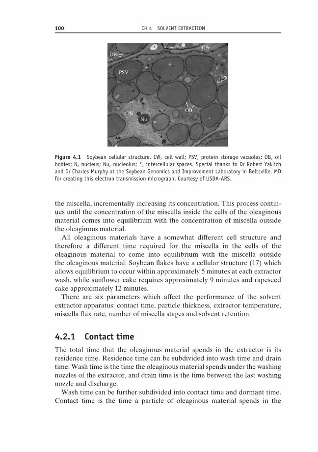
100 CH 4 SOLVENT EXTRACTION
OB
OB
CW
PSV
NNu
Figure 4.1 Soybean cellular structure. CW, cell wall; PSV, protein storage vacuoles; OB, oilbodies; N, nucleus; Nu, nucleolus; *, intercellular spaces. Special thanks to Dr Robert Yaklichand Dr Charles Murphy at the Soybean Genomics and Improvement Laboratory in Beltsville, MDfor creating this electron transmission micrograph. Courtesy of USDA-ARS.
the miscella, incrementally increasing its concentration. This process contin-ues until the concentration of the miscella inside the cells of the oleaginousmaterial comes into equilibrium with the concentration of miscella outsidethe oleaginous material.
All oleaginous materials have a somewhat different cell structure andtherefore a different time required for the miscella in the cells of theoleaginous material to come into equilibrium with the miscella outsidethe oleaginous material. Soybean flakes have a cellular structure (17) whichallows equilibrium to occur within approximately 5 minutes at each extractorwash, while sunflower cake requires approximately 9 minutes and rapeseedcake approximately 12 minutes.
There are six parameters which affect the performance of the solventextractor apparatus: contact time, particle thickness, extractor temperature,miscella flux rate, number of miscella stages and solvent retention.
4.2.1 Contact timeThe total time that the oleaginous material spends in the extractor is itsresidence time. Residence time can be subdivided into wash time and draintime. Wash time is the time the oleaginous material spends under the washingnozzles of the extractor, and drain time is the time between the last washingnozzle and discharge.
Wash time can be further subdivided into contact time and dormant time.Contact time is the time a particle of oleaginous material spends in the

4.2 SOLVENT EXTRACTOR 101
washing zone of the extractor during which it is in contact with miscella. Oilextraction only takes place during contact time. Dormant time is the time theparticle spends in the washing zone of the extractor during which it is not incontact with miscella. The ratio of contact time to dormant time varies withextractor design.
Extractors with high material bed depth and small bed surface area aregenerally operated by immersing the oleaginous materials in miscella. This isaccomplished by providing a sufficient miscella flow rate per unit of materialbed surface area in order to ensure that miscella fills all the voids aroundthe oleaginous material particles as it passes down through the material bed.This type of extractor operation provides a very high ratio of contact time todormant time in the washing zone.
Extractors with low bed depth and large bed surface area are generallyoperated by percolating the miscella down through the oleaginous materials.With most oleaginous materials, the oleaginous material particles occupy40–50% of the material bed, with the remaining 50–60% composed of voidspaces between the particles. In percolation, the oleaginous material particlesare surrounded by both solvent vapour and miscella as the miscella rainsdownward. This type of extractor operation provides a lower ratio of contacttime to dormant time in the washing zone.
In comparing two different extractor designs, the contact time can be similardespite very different configurations:
(1) Deep-bed extractor example: 50 minutes’ residence time = 30 minutes’wash time + 20 minutes’ drain time; 30 minutes’ wash time – 5 minutes’dormant time = 25 minutes’ contact time.
(2) Shallow-bed extractor example: 50 minutes’ residence time = 45 minutes’wash time + 5 minutes’ drain time; 45 minutes’ wash time – 20 minutes’dormant time = 25 minutes’ contact time.
Regardless of extractor design, adequate contact time is critical for maximis-ing extraction efficiency and minimising the amount of residual oil remainingin the oleaginous material. Increased contact time requires a larger extractor.Even though this represents a higher initial investment, the long-term eco-nomic benefits of reduced residual oil content as a result of surplus contacttime are significant and justify oversizing the extractor.
4.2.2 Particle thicknessVarious oleaginous materials are prepared for extraction using differentprocess steps, but one process step that virtually all oleaginous materialshave in common is flaking. The principal purpose of flaking is to reducethe thickness of the oleaginous material in order to reduce the distance and

102 CH 4 SOLVENT EXTRACTION
the number of cell walls that miscella needs to diffuse through in order toreach the oil bodies. Note that for soybeans, a typical 0.38 mm-thick flakeis approximately 20 cells thick. By reducing the particle thickness, the timerequired for the miscella within the cellular structure of the oleaginousmaterial to reach equilibrium with the miscella surrounding the oleaginousmaterial is reduced; also, desired results can be achieved with less contacttime. If all other extraction parameters remain constant, reduced particlethickness will allow a smaller extractor to be used.
Reducing particle thickness represents additional cost. For example, withsoybeans, reducing particle thickness from 0.38 mm to 0.30 mm will increaseflaking mill electricity requirements by 1–2 kwh/tonne of soybeans processed.Since this is a significant ongoing operating expense, it is not economicallyfeasible to undersize an extractor and reduce particle thickness. Conversely,by increasing particle thickness, the desired results will demand more contacttime. An extractor can be oversized in order to obtain the desired results withincreased particle thickness, thereby reducing the ongoing operating cost.
For all oleaginous materials, the economic balance between the initial costof the extractor and the ongoing electricity costs required for flaking can beanalysed and the optimum particle thickness determined.
4.2.3 Extractor temperatureAs the temperature of the miscella increases, its rate of diffusivity through thecell walls of the oleaginous material increases. Since the prepared oleaginousmaterial enters the extractor at approximately 60 ◦C and both the oil and mealfractions are heated in excess of 100 ◦C in subsequent process steps, there isno extra energy required to operate the extractor at a warm temperature. Asa result, optimising extraction results requires operating the extractor at ashigh a temperature as is possible.
There is a practical upper limit for the extractor operating temperature.The solvent must remain safely in a liquid state. Since the boiling range ofcommercial hexane is typically 64–69 ◦C at sea level, the maximum possibletemperature without boiling is 63 ◦C. Operating on the edge of the boilingrange may cause rapid evaporation during an upset condition. Rapid evapo-ration can cause pressurisation of the extractor, leading to excessive solventloss: a safety hazard. Therefore, most processors operate the extractor at60 ◦C in order to provide several degrees Celsius of safety margin below thelower end of the solvent boiling range.
If the prepared material temperature is too low, or heat loss in the extractoris too high, then it may not be possible to achieve an extractor temperatureof 60 ◦C. Additional contact time will be required in order to achieve desiredresults. Insulating the conveying system and extractor to prevent heat loss

4.2 SOLVENT EXTRACTOR 103
and enable operation at 60 ◦C is typically less expensive than oversizing theextractor to compensate for a low operating temperature.
4.2.4 Miscella flux rateThe miscella flux rate is the maximum volumetric flow rate of miscella that canflow down through the bed of material per unit of material bed surface area.In SI units, it is commonly expressed as m3/hour per m2, while in Imperialunits it is commonly expressed as gpm per ft2. By simplification of units,the miscella flux rate can also be expressed as the downward velocity of thehead of miscella before entering the material bed (in m/minute or ft/minute).Miscella flux rates for various prepared oleaginous materials vary widely (seeTable 4.1).
The miscella flux rate is determined by the screen below the bed ofmaterial. As stated earlier, the material bed is approximately 40–50% solidsand 50–60% void space. Therefore, as the miscella is moving downward,it has 50–60% open area to pass through. The screen under the materialbed has less open area, and therefore the material interface with the screencreates the greatest restriction to flow. Most deep-bed extractor screens haveapproximately 30% open area, whereas most shallow-bed extractor screenshave less than 10% open area. In both cases, the screens have less openarea than the material bed itself, and the material interface with the screenprovides the greatest flow restriction.
As downward miscella flow reaches the miscella flux rate, thematerial–screen interface reaches its maximum flow rate and beginsrestricting the flow of miscella. All void spaces between the oleaginousmaterial particles fill with miscella as the solvent vapours are pushed outthe top of the material bed. Eventually, the entire material bed becomesimmersed in miscella, with no void spaces. At this point, miscella breaksthrough the top of the miscella bed and forms a pool. This phenomenonis often referred to as ‘flooding’ of the material bed. Once the material bed is
Table 4.1 Miscella flux rates.
m3/hour/m2 gpm/ft2 m/minute ft/minute
Cottonseed flakes (0.38 mm) 10 4 0.17 0.53Cottonseed extrudate 30 12 0.50 1.60Rapeseed cake 20 8 0.33 1.07Soybean flakes (0.30 mm) 15 6 0.25 0.80Soybean flakes (0.38 mm) 20 8 0.33 1.07Soybean extrudate 45 18 0.75 2.40Sunflower cake (ground) 25 10 0.42 1.33

104 CH 4 SOLVENT EXTRACTION
flooded, the rate of flow passing down through the material bed cannot beincreased.
At each washing stage of the extractor, miscella needs to have an opportu-nity to wash the material bed, pour through the screen and enter the propermiscella collection receptacle beneath the material bed. For a given extractorand prepared oleaginous material, each miscella collection receptacle is care-fully calculated to be located a specific distance from its washing nozzle, inorder to maintain separation between washing stages. For example, if there isa deep-bed extractor operating on 0.38 mm-thick soybean flakes with a 3.0 mbed depth and a forward material velocity of 0.3 m/minute, the distance thatthe miscella collection receptacle needs to follow the washing nozzle by canbe calculated as follows:
Downward head miscella velocity for 0.38mm − thick
soybean flakes = 0.33m/minute
Void space between 0.38mm − thick soybean flakes = 57%
Downward flake bed miscella velocity = 0.33m/minute ÷ 0.57
= 0.58m/minute
Time for miscella to pass through material bed = 3.0m
÷0.58m/minute = 5.2 minutes
Wash nozzle to miscella receptacle distance = 5.2 minutes
×0.3m/minute = 1.6m
As another example, if there is a shallow-bed extractor operating on 0.38 mm-thick soybean flakes with a 0.75 m bed depth and a forward velocity of1.2 m/minute, the distance that the miscella collection receptacle needs tofollow the washing nozzle by can be calculated as follows:
Downward head miscella velocity for 0.38mm − thick
soybean flakes = 0.33m/minute
Void space between 0.38mm − thick soybean flakes = 57%
Downward flake bed miscella velocity = 0.33m/minute ÷ 0.57
= 0.58m/minute
Time for miscella to pass through material bed = 0.75m
÷0.58m/minute = 1.3 minutes
Wash nozzle to miscella receptacle distance = 1.3 minutes
×1.2m/minute = 1.6m

4.2 SOLVENT EXTRACTOR 105
If the miscella flux rate is significantly reduced for a given prepared oleaginousmaterial, the miscella can partially discharge into a later, undesired miscellacollection receptacle. This will cause concentration contamination due tomixing of the extractor washes and reduce the efficiency of the extractor.
Miscella flux rates can reduce as a result of thinner-than-normal flakes,surface moisture or an abundance of fine particles. Flake thickness is a normaloperator-controlled parameter, but surface moisture and an abundance offine particles are more difficult to control.
Since hexane solvent is not soluble in water, the liquids repel each other.If surface moisture exists on the material in the extractor, the solvent willhave difficulty penetrating the particle surface. Also, the moisture can collecton the screen at the bottom of the material bed, building a protein layerand narrowing the screen slots, further reducing the miscella flux rate. Toprevent this from occurring, it is very important to adequately aspirateflakes from flaking mills, cake from screw presses or extruded pellets fromextruders in order to remove all water vapour created when the materialevaporatively cools from preparation temperature to extraction temperature.As a secondary precaution, it is ideal to have an extractor designed suchthat the oleaginous material moves with respect to the screen surface so asto constantly keep the screen surface brushed clean, so that the impact ofsurface moisture on miscella flux rate is minimised.
The material bed is approximately 40–50% material particles and 50–60%void space. If there is an abundance of fine material particles, these particlescan sift down through the material bed and settle in the void spaces justabove the screen. This causes an additional flow restriction and the miscellaflux rate will be reduced. An abundance of fine material at the extractor isgenerally caused by overdrying of the material at some point in the seedpreparation stage or by rough handling of the friable material during a seedpreparation step. Both should be avoided, so as to ensure a uniform materialshape at the extractor and uniform miscella flux rates.
4.2.5 Number of miscella stagesIn most extraction applications, the prepared material has approximately 20%oil by weight and the goal is to reduce the oil content to approximately 0.5%by weight. If an extractor has one miscella stage, the miscella concentrationexiting the extractor (1.15% oil) will be in equilibrium with the miscellaconcentration remaining in the material cells (1.15% oil). A mass balance fora single-stage extractor can be calculated (see Table 4.2). An extractor whichhas only one miscella stage will require 17.2 parts of solvent per 1.0 part ofmaterial to be extracted. The energy required to evaporate the solvent in the

106 CH 4 SOLVENT EXTRACTION
Table 4.2 Single-stage extractor mass balance.
Prepared material entering Solvent enteringSolids: 800 units Solvent: 17 200 units
Oil (20%): 200 unitsTotal: 1000 units Total: 17 200 units
Spent material exiting Miscella exitingSolids: 800 units Solvent: 16 856 units
Oil (0.5% residual): 4 units Oil: 196 unitsSolvent (30% retention): 344 units
Total: 1148 units Total: 17 052 unitsMiscella concentration Miscella concentration
4 / (4 + 344) = 1.15% oil 196 / (196 + 16 856) = 1.15% oil
miscella will be tremendous. As a result, countercurrent multistage extractorsare required.
Through iteration of the mass balance, the minimum number of mis-cella stages can be calculated for a given solvent–material ratio. For anenergy-competitive distillation system, the solvent–material ratio should bemaintained below 1 : 1 in order to maintain a full miscella concentration of23% oil by weight or greater. The minimum number of stages required toachieve 0.5% residual oil with 23% miscella concentration can be calculatedas four.
A four-stage extractor with sufficient contact time to allow the miscella con-centration in the material cells to come into equilibrium with the miscellaconcentration in the surrounding miscella bath at each miscella stage can bedesigned to extract to less than 0.5% residual oil using a solvent–materialratio of 1 : 1. The resultant outgoing miscella concentration will be approxi-mately 23% oil. A four-stage extractor is sufficient theoretically, but leavesno contingency for failure to achieve equilibrium at each miscella stage.
The more miscella stages, the greater the theoretical extraction efficiency.In practice, however, if too many miscella stages are designed into anextractor, causing the individual stages to have insufficient contact time toreach equilibrium, residual oil will not be further reduced by the addition ofnew stages. In this case, more miscella stages simply leads to more pumps,and therefore more pumping energy and more potential points for solventloss. The number of miscella stages is generally determined by the totalwashing zone time and the number of stages that can theoretically come toequilibrium within the washing zone time. Commercially, most extractorshave somewhere in the range of five to nine miscella stages.
Increasing the solvent flow to the extractor in order to increase thesolvent–material ratio and reduce the full miscella concentration can reducethe number of miscella stages required, although this is not cost-effective dueto the distillation energy required to evaporate the additional solvent. Veryhigh solvent–material ratios (full miscella concentrations well under 23%)

4.3 MEAL DESOLVENTISER TOASTER 107
are only justified in specialty oil extractions with extremely high incrementaloil values.
4.2.6 Solvent retentionAfter leaving the washing zone of the extractor, the extracted material is leftto drain by gravity. This gravity drain time is generally in the range of 5–20minutes. Extractors designed with low material bed depths will generallyhave a drain time closer to 5 minutes, while extractors with high material beddepths will generally have a drain time closer to 20 minutes. After gravitydrainage, the solvent retained with the extracted material will be in the rangeof 25% (fast-draining extrudate) to 32% (slow-draining flakes).
The ‘solvent retention’ of the drained material is something of a misnomer,and could be more accurately defined as the ‘weak miscella retention’. Theweak miscella retained in the drained material contains approximately 1%oil. In the meal desolventiser, the solvent is evaporated, leaving behind tracesof oil, often referred to as the residual oil. In order to minimise the residual oilleft in meal, it is important to minimise the amount of weak miscella carriedforward to the meal desolventiser.
An adequate extractor drain time is the most economical means by which tominimise weak miscella retention. Maintaining the desired miscella flux rateis also important. Thus, once again, there is a need to maintain proper flakethickness, minimise surface moisture and minimise fine material particles inthe material bed in order to minimise weak miscella retention.
Today there are two major suppliers of solvent extractors: Crown IronWorks, headquartered in the USA, and Desmet Ballestra, headquartered inBelgium. The Crown Model III Extractor is a shallow-material bed extractorwhich utilises a chain conveyor design to convey the material over fixedscreens in a loop pattern (see Figure 4.2). Desmet Ballestra supplies twomajor types of extractor: a Reflex® Extractor and an LM™ Extractor. TheDesmet Ballestra Reflex® Extractor is a deep-material bed extractor whichuses a cylindrical rotating set of baskets to convey the material over a fixedcircular screen (see Figure 4.3). The Desmet Ballestra LM™ Extractor isprovided in both shallow and deep material bed versions, both utilising a beltconveyor made of screens to convey the material along a linear path (seeFigure 4.4). Extractors of these three types process somewhere in the rangeof 25 tonnes per day of specialty oilseeds to 10 000 tonnes per day of soybeansthrough a single unit.
4.3 Meal desolventiser toasterAfter the prepared material has had its oil extracted in the solvent extractor,it is conveyed to the meal desolventiser toaster, commonly referred to as the
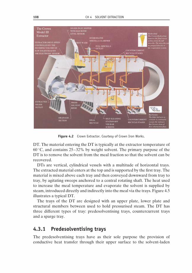
108 CH 4 SOLVENT EXTRACTION
SOLIDS INLET HOPPER
WITH ELECRONIC
LEVEL SENSOR
EXTRACTED
SOLIDS
OUTLET
DRAINAGE
SECTION
FIRST WASH
HYDRODLONE
MISCELLA CLARIFIER
FULL MISCELLAOUTLET
COUNTERCURRENT
RECYCLE STAGES
HydrocloneThe Crown Hydrocloneremoves the final tracesof fines from the fullmiscella. The miscella canbe pumped directly tothe evaporation system.
Bar ScreenThe flake bed acts asa brush–it continuallysweeps the statioaryBar Screen clean offlow-obstruction fines.
FINAL
RECYCLE
COUNTERCURRENT
RECYCLE STAGES
SELF-SLEANING
STATIONARY
VEE-BAR
SCREENS
FRESH
SOLVENT
RINSE
The CrownModel IIIExtractor
EXTRACTOR DRIVE-SPEED
CONTROLLES BY THE
INCOMING VOLUMN OF
RAW SOLIDS READ BY
THE ELECTRONIC SENSOR
Figure 4.2 Crown Extractor. Courtesy of Crown Iron Works.
DT. The material entering the DT is typically at the extractor temperature of60 ◦C, and contains 25–32% by weight solvent. The primary purpose of theDT is to remove the solvent from the meal fraction so that the solvent can berecovered.
DTs are vertical, cylindrical vessels with a multitude of horizontal trays.The extracted material enters at the top and is supported by the first tray. Thematerial is mixed above each tray and then conveyed downward from tray totray, by agitating sweeps anchored to a central rotating shaft. The heat usedto increase the meal temperature and evaporate the solvent is supplied bysteam, introduced directly and indirectly into the meal via the trays. Figure 4.5illustrates a typical DT.
The trays of the DT are designed with an upper plate, lower plate andstructural members between used to hold pressurised steam. The DT hasthree different types of tray: predesolventising trays, countercurrent traysand a sparge tray.
4.3.1 Predesolventising traysThe predesolventising trays have as their sole purpose the provision ofconductive heat transfer through their upper surface to the solvent-laden
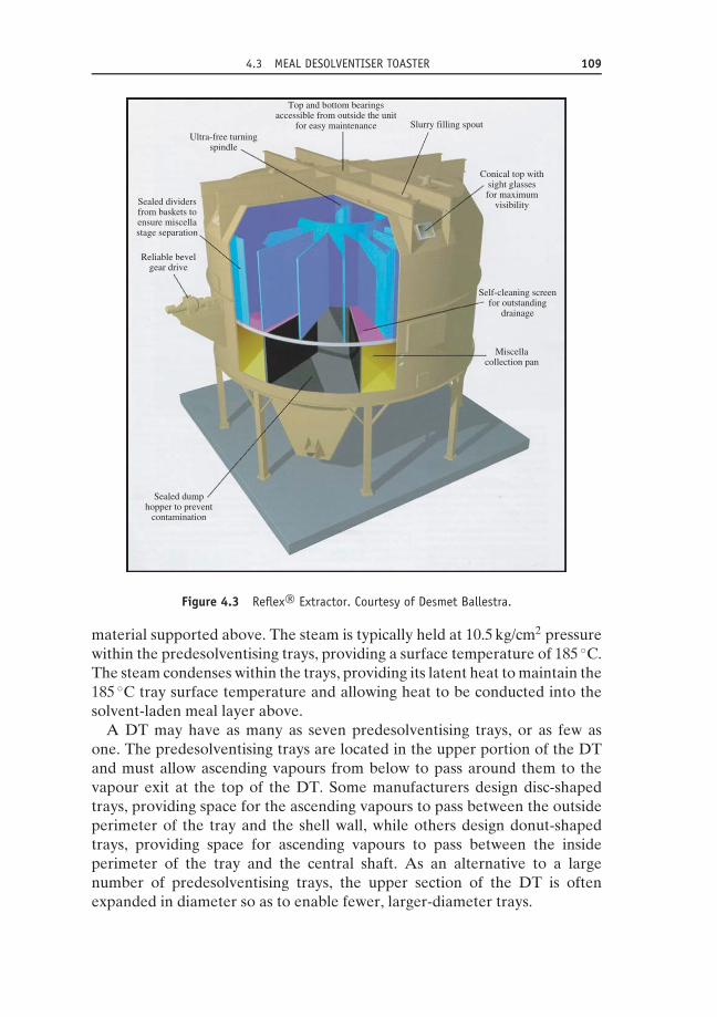
4.3 MEAL DESOLVENTISER TOASTER 109
Sealed dumphopper to prevent
contamination
Reliable bevelgear drive
Sealed dividersfrom baskets toensure miscellastage separation
Ultra-free turningspindle
Top and bottom bearingsaccessible from outside the unit
for easy maintenance Slurry filling spout
Conical top withsight glassesfor maximum
visibility
Self-cleaning screenfor outstanding
drainage
Miscellacollection pan
Figure 4.3 Reflex® Extractor. Courtesy of Desmet Ballestra.
material supported above. The steam is typically held at 10.5 kg/cm2 pressurewithin the predesolventising trays, providing a surface temperature of 185 ◦C.The steam condenses within the trays, providing its latent heat to maintain the185 ◦C tray surface temperature and allowing heat to be conducted into thesolvent-laden meal layer above.
A DT may have as many as seven predesolventising trays, or as few asone. The predesolventising trays are located in the upper portion of the DTand must allow ascending vapours from below to pass around them to thevapour exit at the top of the DT. Some manufacturers design disc-shapedtrays, providing space for the ascending vapours to pass between the outsideperimeter of the tray and the shell wall, while others design donut-shapedtrays, providing space for ascending vapours to pass between the insideperimeter of the tray and the central shaft. As an alternative to a largenumber of predesolventising trays, the upper section of the DT is oftenexpanded in diameter so as to enable fewer, larger-diameter trays.

110 CH 4 SOLVENT EXTRACTION
Figure 4.4 LM™ Extractor. Courtesy of Desmet Ballestra.
HOT VAPOURSTO FIRST STAGE
VAPOUR WASHEXTRACTEDFLAKE INLET
1 PRE-D.T.TRAYS
3 SPARGE TRAY
VARIABLESPEEDROTARYVALVE
2 HOLLOWSTAYBOLT
TRAYS
Figure 4.5 Desolventiser toaster. Courtesy of Crown Iron Works.

4.3 MEAL DESOLVENTISER TOASTER 111
4.3.2 Countercurrent traysThe countercurrent trays have three purposes: to provide conductive heattransfer through their upper surface in order to warm wet material supportedabove; to provide convective heat transfer through their lower surface inorder to superheat direct steam swirling below; and to provide apertures toallow direct steam to evenly ascend up through the tray and into the mealsupported above. The steam is typically held at 10.5 kg/cm2 pressure withinthe countercurrent trays, providing a surface temperature of 185 ◦C. Steamcondenses within the trays, providing its latent heat to maintain the 185 ◦Ctray surface temperature and allowing heat to be conducted into the meallayer above and transferred into the direct steam swirling below.
A DT will have from one to four countercurrent trays. The countercurrenttrays are located directly under the predesolventising trays in the centreof the DT. The apertures in the trays must allow the direct steam swirlingbelow to pass through and into the meal supported above. There are threedesigns of countercurrent tray, with different apertures: initial modern DTs bySchumacher, circa 1982, utilised hollow stay-bolts as apertures and generallyhad a 1–2% open area to allow the vapours to ascend (Schumacher, 1985);a later modern DT design by Mason, circa 1985, utilised hollow stay-pipescapped by a perforated plate, with generally 2–4% open area to allowvapours to ascend; while the latest modern DT design by Kemper, circa1997, utilises hollow stay-pipes capped with stainless-steel slotted screens,with approximately 10% open area to allow the vapours to ascend (Kemper& Farmer, 1999). A greater open area in the countercurrent trays allowsfor more uniform steam distribution and has been the trend in modernDT design.
4.3.3 Sparge trayThe sparge tray has the dual purpose of providing a uniform means ofintroducing direct steam into the meal layer and providing conductive heattransfer through its upper surface to the wet material supported above. Thedirect steam introduced through the sparge tray provides approximately 75%of the total heat required to desolventise and heat the meal in the DT. Thesparge tray is typically designed with a plurality of apertures across its entireupper surface, in order to evenly introduce direct steam into the meal. Thesize and quantity of apertures is calculated based upon the anticipated directsteam flow rate so as to provide a pressure drop of 0.35–0.70 kg/cm2. Thedirect steam supply is 10.5 kg/cm2 pressure saturated steam (185 ◦C). Afterpassing through a flow-control valve, its quality changes to 0.35–0.70 kg/cm2
pressure superheated steam (150–160 ◦C). Therefore, the upper surface ofthe sparge tray is maintained at approximately 155 ◦C.

112 CH 4 SOLVENT EXTRACTION
Solvent-laden meal enters the DT at a temperature of 60 ◦C and contains25–35% by weight solvent. The solvent-laden meal is stirred across thesurface of the predesolventising trays by the rotating sweeps. Since the heat istransferred into the meal layer by conduction, a shallow layer of 150–300 mmmeal depth is held above each tray. The solvent-laden meal temperature isincreased to approximately 68 ◦C, and approximately 10–25% of the solventis evaporated on the predesolventising trays.
The material exits the predesolventising trays of the DT and falls on to thetop countercurrent tray. This is perhaps the most critical tray of the DT. Sincemost of the heat is transferred into the meal layer by condensation of directsteam, a deep layer of 1000–1200 mm meal depth is held above the tray.The solvent-laden meal is stirred above the top countercurrent tray by therotating sweeps. The direct steam passes from below up through aperturesin the countercurrent tray. As the direct steam penetrates the upper meallayer, it reaches the solvent-laden meal and condenses, providing direct latentheat to evaporate the solvent, which exits the meal layer as vapour. Thecondensation of steam causes the meal exiting the tray to be wet, typically inthe range of 17–21% moisture. After the majority of the solvent evaporates,the meal temperature increases via direct and indirect steam heat, surpassing100 ◦C before the material exits the tray. The protein solubility of soybeanmeal is reduced from approximately 90 to 45 PDI as a result of the elevatedmoisture and temperature conditions.
Once the wet meal exits the top countercurrent tray, it has had over 99%of its solvent removed. On the remaining countercurrent trays and the spargetray, the meal is typically held in a 1000 mm-deep layer, in order to provideresidence time to allow solvent stripping and toasting. The wet meal is stirredabove each tray by rotating sweeps. The final desolventising takes place as theascending steam passing through the meal slowly strips out the final traces ofresidual solvent, down to 100–500 ppm. The meal temperature increases from100 to 105–110 ◦C and the meal moisture decreases approximately 1% beforethe meal discharges from the sparge tray. The meal colour darkens slightly,providing the meal with a toasted colour. For soybeans, antinutritional factorssuch as trypsin inhibitors and urease are reduced on these trays by maintainingthe meal moisture and temperature elevated for a period of time. The proteinsolubility drops approximately 1% PDI for every minute the meal spendsin the remaining countercurrent trays and the sparge tray. Ideal feed formonogastric animals (poultry and swine) is high in protein solubility, andideal feed for ruminant animals (cattle) is low in protein solubility (high inrumen bypass protein). Meal residence time on the remaining countercurrenttrays and the sparge tray is dictated by both the degree of solvent recoveryrequired and meal quality parameters.
An important parameter in the energy efficiency of the DT is the exit vapourtemperature. The condensing sparge steam provides a plentiful supply of

4.3 MEAL DESOLVENTISER TOASTER 113
105
100
95
90
Dew
poin
t te
mpe
ratu
re (
°C)
85
80
75
70
65
60
550 10 20 30 40
Weight % hexane with water
Liquidphase
Phase equilibriumhexane & water
(760 mmHg absolute pressure)
Vapourphase
50 60 70 80 90 100
Figure 4.6 Solvent–water equilibrium boiling curve.
surface moisture, allowing the solvent and water to evaporate as an azeotropicmixture. Figure 4.6 indicates the solvent–water equilibrium boiling curve. Asthe chart shows, a mixture of 94% solvent with 6% water can boil at aslow as 62 ◦C. Therefore, the lowest possible DT exit vapour temperature is62 ◦C. In practice, in order to maintain low solvent loss and a safety margin,modern DTs are operated with exit vapour temperatures ranging from 66to 78 ◦C, with the most typical temperature being 71 ◦C. As the DT vapourtemperature increases, the ratio of water vapour to solvent vapour increases.Therefore, to minimise total DT energy, it is very important to maintain avapour temperature as low as is safely possible.
Determining the optimum DT configuration for a given process applicationis a rather complex process. It requires the determination of all input param-eters and calculation of the mass and heat balance of both the DT and thefollow-on meal dryer cooler (DC). The mass and heat balance of the DC willdetermine the maximum allowable DT exit moisture, which will minimisemeal drying energy. This moisture is generally in the range of 18–20%. Withthe DT exit moisture determined, the amount of direct steam introducedinto the meal can be calculated. The DT diameter is generally determinedby the direct steam flow rate per unit area. It is important to have a suffi-ciently high direct steam flow rate per unit area to allow adequate solventstripping. The number of countercurrent trays is determined by the residence

114 CH 4 SOLVENT EXTRACTION
time required to balance meal quality with residual solvent objectives. Bycalculating the total DT heat demand and subtracting the heat supplied bylive steam, the total heat supplied by indirect steam can be determined.Subtracting the heat supplied by countercurrent tray indirect steam fromthe total heat supplied by indirect steam will provide the amount of indirectsteam heat that must be supplied by the predesolventising trays. With thisinformation in hand, the diameter and quantity of predesolventising trays canbe selected. Major manufacturers of DTs utilise process simulation tools toassist processors in optimising the DT configuration for a given application.
4.4 Meal dryer coolerAfter the solvent-laden material is desolventised, it is conveyed to the DC.The material entering the DC is typically at the DT exit temperature of108 ◦C, and contains 18–20% moisture (for soybeans). The primary purposesof the DC are to reduce the moisture in the meal to within trading rule limitsand to lower the meal temperature prior to storage.
DCs are vertical, cylindrical vessels with a multitude of horizontal trays.The desolventised material enters at the top and is supported by the tray. Thematerial is mixed above each tray and conveyed downward from tray to trayby agitating sweeps anchored to a central rotating shaft. The DC has threedifferent types of tray: steam-drying trays, air-drying trays and air-coolingtrays.
4.4.1 Steam-drying traysThe steam-drying trays of the DC are designed with an upper plate, lowerplate and structural members between them designed to hold pressurisedsteam. The steam-drying trays have the purpose of providing conductiveheat transfer through their upper surface to wet meal supported above.The steam is typically held at 10.5 kg/cm2 pressure within the steam-dryingtrays, providing a surface temperature of 185 ◦C. Steam condenses within thetrays, providing its latent heat to maintain the 185 ◦C tray surface temperatureand allowing heat to be conducted into the wet meal layer above.
A DC may have as many as five steam-drying trays, or as few as none. Thewater vapour evaporated from the meal can be compressed in an ejector andhave its heat recovered within the solvent extraction plant.
4.4.2 Air-drying traysThe air-drying trays of the DC are designed with an upper plate, lower plateand structural members between them designed to hold low-pressure air.The air-drying trays are designed with a plurality of apertures across their

4.4 MEAL DRYER COOLER 115
entire upper surface in order to evenly introduce air into the meal. The sizeand quantity of apertures is calculated based upon the design air flow rateso as to provide a pressure drop of 0.02–0.03 kg/cm2. These apertures aregenerally small round holes, but Desmet Ballestra has recently introducedpatent-pending technology that utilises narrow slots.
The air supplied to each air-drying tray is first filtered to remove dust andthen pressurised using a centrifugal blower. The air for the dryer trays ispassed through a steam-heated coil between the blower and the entrance tothe trays. After the air enters the trays, it flows upward through the meal ata nominal velocity of 14–21 m/minute, partially fluidising the meal. The mealevaporatively cools and the released moisture is transferred to the ascendingair. The warm, damp air exits the top of the meal layer and then movesthrough the sidewall of the DC to a cyclone collector in order to remove dustprior to discharge to atmosphere. Figure 4.7 illustrates a meal DC with twoair trays and related air-handling equipment.
The major source of heat for evaporation of the moisture in the meal is thehigh temperature of the meal exiting the DT or the DC steam-drying trays.When the meal drops in temperature from 108 to 38 ◦C, the heat providedis adequate to reduce the meal moisture by 6.5%. For soybean meal, thetrading rule moisture limit is 12.5%; therefore, if the incoming moisture fromthe DT, or the DC steam-drying trays, does not exceed 19.0%, the DC willtypically require no additional evaporative heat source in order to dry themeal. If additional heat is required to evaporate moisture from the meal,the air entering the meal dryer trays can be heated to up to 150 ◦C prior toentering the air-drying trays. The heat source may be recovered flash steam,hot glycol–water solution (oil cooler) or fresh steam.
Figure 4.7 Meal dryer cooler. Courtesy of Desmet Ballestra.

116 CH 4 SOLVENT EXTRACTION
The air must have adequate capacity to carry the moisture released fromthe meal without becoming saturated. Cold air can hold less moisture thanwarm air, so winter conditions may limit the moisture-carrying capacity ofthe air. If additional heat is required to increase the dew point of the incomingair, the air entering the air dryer trays can be heated to temperatures up to150 ◦C.
The energy required to heat the incoming drying air is largely dictatedby the meal moisture coming into the DC. Adequate predesolventising heattransfer area in the DT or steam-drying tray heat transfer area in the DC isthe key to minimising meal moisture to the DC air-drying trays and thereforeto minimising DC heater coil steam consumption.
4.4.3 Air-cooling traysThe air-cooling trays of the DC are designed with an upper plate, lower plateand structural members between them designed to hold low-pressure air.The air-cooling trays are designed with a plurality of apertures across theirentire upper surface so as to evenly introduce air into the meal. The sizeand quantity of apertures is calculated based upon the design air flow rate toprovide a pressure drop of 0.02–0.03 kg/cm2.
The air supplied to each air-cooling tray is first filtered to remove dustand then pressurised using a sparkproof centrifugal blower. After the coolair enters the trays, it flows upward through the meal at a nominal velocityof 14–21 m/minute, partially fluidising the meal. The meal continues toevaporatively cool, and also convectively cools. The cool, damp air exits thetop of the meal layer and then moves through the sidewall of the DC to acyclone collector in order to remove dust prior to discharge to atmosphere.
Ambient air is heated by approximately 5 ◦C by the energy of the blower,before it blows into the air-cooling trays of the DC. The meal cools towithin approximately 5 ◦C of the air temperature passing through the meal.Therefore, the temperature of the meal exiting the DC is typically cooled towithin 10 ◦C of ambient air. A suction blower fitted downstream of the DCcan thus reduce exit meal temperatures by up to 5 ◦C by avoiding the heatingenergy of the upstream blower.
The dry cool meal is conveyed from the DC outside the solvent extractionplant to allow size reduction and then on to meal storage. It is impor-tant to properly dry and cool the meal in order to prevent continuedevaporative cooling in storage or transport, which will cause reduced flowa-bility, solidification and bridging of the meal inside storage and transportvessels.

4.5 MISCELLA DISTILLATION SYSTEM 117
4.5 Miscella distillation systemThe miscella exiting the extractor contains up to 1% by weight particlesof meal. Therefore, the first step in miscella distillation is meal particleseparation. Meal particles can be separated from the miscella by filtrationor centrifugal separation. The large meal particles (+80 mesh) need to beremoved in order to prevent them from settling out in the distillation equip-ment. The fine meal particles (−80 mesh) are removed from the oil aftersolvent extraction, typically in the oil degumming process or oil refining pro-cess. For those plants producing food-grade lecithin, the fine meal particlesmust be completely filtered out prior to degumming.
Some extractor designs include an internal miscella filter (100 mesh),enabling the miscella exiting the extractor to be sufficiently free of mealparticles to go directly to distillation. Other extractor designs require externalmeal particle separation, accomplished by pumping the miscella through aliquid cyclone. The liquid cyclone spins the miscella at high velocity andutilises centrifugal force to separate the larger meal particles (over 80 mesh)from the miscella. The larger meal particles, along with 5–10% of the miscellaflow, exit the liquid cyclone underflow orifice and return to the extractor.Separation of meal particles by external filtration of the miscella is not rec-ommended due to the safety hazards associated with opening the filter toremove the solvent-laden meal fines.
Once the large meal particles are separated, the clean miscella is stored in asurge tank, generally referred to as a full miscella tank. The full miscella tankhas several purposes: it separates the continuous extraction process from thecontinuous distillation process, it provides miscella storage capacity during apower outage and it provides surge capacity so that fluctuations in miscellaflow rate from the extractor can be absorbed prior to distillation. The miscellain the full miscella tank is generally 25–30% oil and 70–75% solvent byweight, and exists at the typical extractor temperature of 60 ◦C.
The miscella is pumped from the full miscella tank to the first of tworising film evaporators. The first-stage evaporator, often referred to as theeconomiser, utilises the waste heat from the DT as its heating source.Miscella enters through tubes at the base of the evaporator, at a temperatureof approximately 60 ◦C. Since the tube side of the evaporator is held atapproximately 300–400 mmHg absolute pressure, the miscella temperaturewill drop to approximately 43–48 ◦C temperature upon entry into the tubes.Solvent will begin evaporating and solvent vapour bubbles will rise up throughthe centre of the tubes. Additional DT vapour heat is transferred throughthe tubes into the miscella and additional evaporation takes place. Whensufficient solvent vapour is formed, the vapour velocity through the centre

118 CH 4 SOLVENT EXTRACTION
of the tubes will become sufficiently high to drag a thin film of miscella upthe inner walls of the tubes, creating high heat transfer rates. At the tops ofthe tubes, the high-velocity solvent vapour and remaining miscella contact animpingement plate to break foam and are then centrifugally separated in theevaporator dome. Solvent vapours exit the top of the dome and concentratedmiscella exits the base of the dome. The concentrated miscella exiting thefirst-stage evaporator is generally 75–85% oil and 15–25% solvent, andapproximately 48 ◦C.
Since the temperature of the miscella exiting the first-stage evaporator islow, it is a good heat sink for heat recovery. In various facilities, heat from hotfinished oil, heat from steam ejector exhausts or recovered flash steam is usedto preheat the miscella to approximately 75 ◦C. The preheated, concentratedmiscella is then typically heated to 110 ◦C in a steam-heated exchanger priorto entering the second rising film evaporator.
The preheated, concentrated miscella is pumped into the second-stageevaporator, which utilises low-pressure steam as its heating source. Since thetube side of the evaporator is held at approximately 300–400 mmHg absolutepressure, the solvent temperature will drop to approximately 43–48 ◦C uponentry into the tubes, providing sufficient heat to immediately begin vigorousevaporation. The vapour velocity through the centre of the tubes will besufficiently high to drag a thin film of miscella up the inner walls of the tubesat relatively high velocity. This is very important for preventing phospatidesand fine solid particles in the miscella from baking to the lower, inner surfaceof the tubes. Additional low-pressure steam heat is transferred through thetubes into the miscella and additional evaporation and heating takes place.At the tops of the tubes, the solvent vapour and remaining miscella contactan impingement plate to break foam and are then centrifugally separatedin the evaporator dome. Since velocities exiting the tubes are insufficient tobreak all foam, the dome must be sufficiently large in diameter to allow theremaining foam to collapse and not discharge with exiting vapours. Solventvapours exit the top of the dome and concentrated miscella exits the base ofthe dome. The concentrated miscella exiting the second-stage evaporator isgenerally 95–98% oil and 2–5% solvent, and approximately 95–110 ◦C.
Miscella from the second-stage evaporator is pumped or gravity-fed intothe oil stripper. The oil stripper is a tall, thin, cylindrical vessel and iscommonly operated at 150–300 mmHg absolute pressure. The hot oil passesdownward through the vessel across trays. Simple, robust disc-donut traysor sieve-type trays are typically utilised, since fouling due to baking of gumsand fine particles on to stripper trays is common. Live steam is introducedinto the oil at the top of the vessel to initiate evaporation, and again at thebase of the vessel to provide countercurrent stripping. The steam and solventvapours exit the top of the oil stripper through an enlarged-diameter dometo prevent entraining of oil mist. The oil typically exits the base of the oil
4.6 SOLVENT RECOVERY SYSTEM 119
stripper with 0.1–0.3% moisture and 5–200 ppm solvent, at a temperature ofapproximately 95–110 ◦C.
The oil leaving the oil stripper, particularly in soybean plants, is often water-degummed. In these facilities, the oil temperature is reduced to 70–80 ◦C, and1–2% soft water is injected and mixed into the oil inline. The oil is then heldfor approximately 30–60 minutes in an agitated tank in order to allow gums tohydrate. The gums (water, phosphatides, fine meal particles and some neutraloil) are centrifugally separated from the oil using a high-speed centrifugalseparator. The gums are often pumped back into the DT and mixed into themeal fraction. Alternatively, the gums may be dried for food-grade lecithin,or feed-grade lecithin for animal feed applications. The degummed oil, at amoisture level of approximately 0.5% and a temperature of approximately70 ◦C, is then heated in a heat exchanger to approximately 110 ◦C.
Whether or not the oil is degummed, it is typically pumped to an oil dryer.The oil dryer is a vertical cylindrical vessel that is commonly operated at50–80 mmHg absolute pressure. The hot oil is sprayed downward into thevessel, with or without trays. The solvent and water vapours exit the top ofthe oil dryer and the oil exits the bottom. The oil typically exits the base of theoil dryer with 0.05–0.10% moisture and 5–100 ppm solvent, at a temperatureof approximately 105 ◦C.
The dried oil must have its temperature reduced from 105 to 50 ◦C in orderto prevent degradation in storage and transport. The hot oil is commonlycooled in two stages. First, the oil is cooled from 105 to approximately 70 ◦Cin a heat exchanger using concentrated miscella or a water–glycol solution(for preheating DC air) as the cooling medium. Second, the oil is cooled from70 to 50 ◦C in a heat exchanger using cooling water as the cooling medium.The cool oil is then pumped to storage.
4.6 Solvent recovery systemModern solvent extraction plants recover over 99.9% of the solvent pumpedto the extractor. The solvent recovery system includes solvent and watervapour condensation, solvent–water separation, stripping of solvent fromwater and air effluent streams and heating of the solvent prior to reuse in theextractor.
The water and solvent vapours from the first- and second-stage evaporatorsas well as the mineral oil stripper are typically condensed in a commonmedium–vacuum condenser. The medium–vacuum condenser is a shell-and-tube vessel, with the vapours typically on the shell side and the coolingwater on the tube side. The noncondensable vapours are removed fromthe condenser by a steam ejector to maintain the 300–400 mmHg absolute

120 CH 4 SOLVENT EXTRACTION
pressure on the shell side and are typically discharged into the first-stageevaporator for heat recovery.
The water and solvent vapours from the edible oil stripper are typicallycondensed in a high-vacuum condenser. The high-vacuum condenser is ashell-and-tube vessel, with the vapours typically on the shell side and thecooling water on the tube side. The noncondensable vapours are removedfrom the condenser by a steam ejector to maintain the 150–300 mmHgabsolute pressure on the shell side and are typically discharged into thewastewater evaporator for heat recovery.
The water and solvent vapours are evacuated from the oil dryer by a steamejector in order to maintain the 50–80 mmHg absolute pressure on the oildryer and are typically discharged into the base of the edible oil stripper.These vapours, along with the ejector motive steam, serve as the edible oilstripper’s source of countercurrent stripping steam for heat recovery.
The solvent and water vapours from the DT typically pass through avapour scrubber to remove meal particles. Two types of vapour scrubberare commonly used: water-spray scrubbers and centrifugal scrubbers. Water-spray scrubbers utilise a heavy spray of hot water droplets sprayed throughthe vapours in the duct exiting the DT to entrap meal particles. The mealparticles and hot water are collected in a tank and recirculated, with a smallstream of dirty water being returned to the DT. Centrifugal scrubbers utilisecentrifugal force to separate meal particles from the vapours, allowing theparticles to fall out the bottom of the scrubber directly into the DT. Somecentrifugal separators use a solvent wash to keep the walls of the centrifugalscrubber clean.
The clean vapours exiting the DT vapour scrubber, along with the muchsmaller vapour streams from the steam ejectors and the wastewater stripper,are partially condensed in the shell side of the first-stage evaporator. Thevapours enter the top of the evaporator shell side at approximately 70 ◦Cand quickly condense water vapour until the temperature drops to 62 ◦C,the minimum hexane–water equilibrium temperature. The vapours continuecondensing at the mixture of 94% solvent and 6% steam and temperatureof 62 ◦C as they progress downward through the shell of the first-stageevaporator. The remaining solvent vapour and water vapour exiting the first-stage evaporator shell (approximately 20–30% of what entered) are furthercondensed in either a vapour contactor or a solvent preheater. In a vapourcontactor, cool condensate from condensers is pumped and sprayed intothe top of a vertical tank. The remaining solvent and water vapours from thefirst-stage evaporator pass through the cool liquid stream and condense on thedroplets, causing the liquid spray temperature to rise. In a solvent preheater,cool fresh solvent en route to the extractor is pumped through the tubes ofa shell-and-tube heat exchanger and the solvent and water vapours from thefirst-stage evaporator pass through the shell side, condensing on the tubes

4.6 SOLVENT RECOVERY SYSTEM 121
while warming the fresh solvent passing through the tubes. Whether using avapour contactor or a solvent preheater after the first-stage evaporator, theremaining DT vapours are reduced to less than 10% of what exited the DT,recovering 90% of the waste heat from the DT. The remaining vapours passon to the vent condenser.
Up to 1 m3 of air enters the extractor with each 1 m3 of material. To maintainthe extractor under a slight vacuum, the air must be continuously vented fromit. At the extractor temperature of 60 ◦C, an equilibrium condition will occur,where the vent gas exiting the extractor will contain approximately 10 parts ofsolvent vapour for every 1 part of air (see Figure 4.8). The solvent vapour andair exit the extractor and are typically condensed in an extractor condenser.The extractor condenser is a shell-and-tube vessel, with the vapours typicallyon the shell side and the cooling water on the tube side. The noncondensablevapours exiting the extractor condenser pass on to the vent condenser.
The vent vapour streams from the extractor condenser, vapour contactoror solvent preheater, and atmospheric tanks pass on to the vent condenser.The normal heat load on the vent condenser is quite low. However, if themiscella is not passing through the first-stage evaporator, or solvent is not
20.019.018.017.016.015.014.0
Pro
port
iona
l vap
our
com
posi
tion
13.012.011.010.09.08.07.06.05.04.03.02.01.00.0
0
AIR
5 10 15
Vapour temperature (°C)20 25 30 35 40 45 50 55 60
WATER VAPOUR HEXANE VAPOUR
Equilibrium Vapour Compositionair & water & hexane
(760 mmHg absolute pressure)
Figure 4.8 Equilibrium vapour composition.
122 CH 4 SOLVENT EXTRACTION
passing through the vapour contactor or solvent preheater, the load on thevent condenser can be very high. Therefore, the vent condenser is generallysized for these contingency conditions and has an excess of heat transferarea for normal operating conditions. The vent condenser is a shell-and-tubevessel, with the vapours typically on the shell side and the cooling water onthe tube side. The noncondensable vapours exiting the vent condenser passon to the mineral oil absorption system.
The composition of solvent vapour with the air exiting the vent condenseris a result of an equilibrium condition determined by the vent gas temper-ature. Figure 4.8 illustrates the equilibrium vapour compositions at varioustemperatures. For example, at a vent gas temperature of 30 ◦C, the vent gascomposition will be slightly greater than 1 part solvent for every 1 part air; ifthe vent gas temperature increases to 40 ◦C, the vent gas composition will beslightly less than 2 parts solvent for every 1 part air. Therefore, to minimisethe load on the mineral oil system, it is important to minimise the vent gastemperature exiting the vent condenser. Some facilities, particularly in hotand humid climates, install a refrigerated vent gas cooler following the ventcondenser in order to minimise the solvent vapour load on the mineral oilsystem.
The vent gas from the process enters the bottom of the mineral oil absorber.The mineral oil absorber is a tall, small-diameter packed column. Cold mineraloil cascades down through the column, absorbing solvent vapour from thevent gas as the vent gas rises up through the packing. When the vent gas exitsthe mineral absorber, it generally contains less than 10 g solvent per 1 m3 ofair. The vent gas is pulled from the mineral oil absorber via a spark resistantsuction fan and is discharged to atmosphere through a flame arrestor.
The mineral oil enters the mineral oil absorber at approximately 30 ◦Cand contains 0.1–0.4% moisture plus solvent. When the mineral oil exitsthe mineral oil absorber, its temperature rises slightly due to the heat ofabsorption and it contains 3–5% moisture plus solvent. The cool solvent-richmineral oil is then heated to 65 ◦C by hot/cool mineral oil heat recovery andthen further heated to over 100 ◦C using a steam-heated heat exchanger. Thehot, solvent-rich mineral oil enters the mineral oil stripper: a packed columnvessel similar in construction to the mineral oil absorber. Since the mineraloil stripper is typically maintained under 300–400 mmHg absolute pressure,much of the solvent evaporates as soon as the mineral oil enters the mineraloil stripper’s top. Most of the remaining solvent is removed as the mineraloil cascades down across the packing countercurrent to the rising strippingsteam. The water and solvent vapour exit the dome of the mineral oil stripper.The hot, solvent-lean mineral oil exits the mineral oil stripper and has itstemperature reduced to 65 ◦C by hot/cool mineral oil heat recovery, and isthen further cooled to 30 ◦C using a heat exchanger with water as the cooling

4.7 HEAT RECOVERY 123
medium. The cool, solvent-lean mineral oil is then recirculated to the top ofthe mineral oil absorber.
All water and solvent that drains from the various condensers in thesolvent extraction plant enters a decanting tank. Since solvent is immisciblewith water, the lighter solvent (0.65 specific gravity) floats above the water.The key to the decanting tank performance is to minimise turbulence withinthe tank, so as to allow sufficient time for gravity decanting to take place. Theelevation of the interface between solvent and water is established by thehighest elevation of the water drain pipe. Water, typically containing 0.01%solvent, exits the decanting tank to the wastewater stripper. Solvent, typicallycontaining 0.05% water, exits the decanting tank to the solvent work tank.
The wastewater stripper is a small tank used to increase the temperature ofthe wastewater to approximately 95 ◦C, in order to evaporate residual solventprior to discharge to the plant sump. The water exiting the wastewater stripperis typically less than 10 ppm solvent. The hot water exiting the wastewaterstripper is often interchanged with the cool water entering the wastewaterstripper for heat recovery.
Solvent enters the work tank from the decanting tank. The work tank isa surge tank used to hold solvent prior to the extractor, in order to ensurethat there is always ample solvent available to be pumped to the extractor.If a large surge of solvent flows into the work tank, the work tank willautomatically overflow to solvent storage. If the level in the work tankbecomes low, additional solvent is pumped from solvent storage to the worktank. The temperature of the solvent in the work tank is typically in the rangeof 52–57 ◦C in plants equipped with a vapour contactor, and 43–49 ◦C inplants without a vapour contactor.
In plants with a vapour contactor, solvent is pumped from the work tank at55 ◦C to a steam-heated solvent heater in order to increase its temperature to60 ◦C prior to entering the extractor. In plants with a solvent preheater ratherthan a vapour contactor, solvent is pumped from the work tank at 45 ◦C to thesolvent preheater, where its temperature is increased to 55 ◦C. The solvent isthen further heated in a steam-heated solvent heater from 55 to 60 ◦C priorto its return to the extractor.
4.7 Heat recoveryWith solvent extraction being a very established technology, many incremen-tal improvements have occurred over the years in the optimisation of heatrecovery between unit processes. Tools such as ‘pinch analysis’ are utilisedtoday to chart and evaluate the available hot streams and cool streams inthe process. Each stream can be plotted on a chart, with temperature on they-axis and heat content on the x-axis.

124 CH 4 SOLVENT EXTRACTION
135T(°C)
115
95
75
55
35
150 5 10 15 20 25 30
Thousand Q(kW)
Figure 4.9 Composite pinch curves.

REFERENCES 125
The vapours from the DT represent a hot stream with high heat contentand moderate temperature, while the vapours from the evaporators havehigh heat content and very low temperature. Several hot streams exist withlow heat content and high temperature, such as edible oil stripper vapours,mineral oil stripper vapours, wastewater evaporator vapours, waste water andedible oil.
The three large cool streams are miscella from the extractor, solvent tothe extractor and air to the DC. A small cool stream is water from thesolvent–water separator.
A composite hot stream and cool stream curve can be plotted (seeFigure 4.9). The temperature range at which the two curves near eachother (the ‘pinch’ range) is then determined. Ideally, heat recovery devicesshould be employed such that cooling water will not be used to cool any indi-vidual hot stream above the upper end of this pinch temperature range andsteam will not be used to heat any individual cool stream below the lower endof this pinch temperature range. Using this tool, modern solvent extractionplants are achieving up to 96% of maximum potential heat recovery in thesolvent extraction process.
ReferencesKemper, T.G. & Farmer, R.D. (1999) US patent 5 992 050 (to French Oil Mill Machinery
Company).Kirschenbauer, H.G. (1944) Fats and Oils. New York, NY: Reinhold Publishing Corp.,
pp. 122–123.Schumacher, H.O. (1985) US patent 4 503 627 (to H.O. Schumacher).Wan, P.J. & Wakelyn, P.J. (1997) Technology and Solvents for Extracting Oilseeds and
Nonpetroleum Oils. Champaign, IL, USA: AOCS Press, pp. 14–18.

5Edible Oil Refining:Current and FutureTechnologiesWim De GreytR&D Manager, Desmet Ballestra Oils and Fats, Zaventem, Belgium
5.1 IntroductionSeveral factors, including a growing world population, higher fat intake percapita and increasing use for technical applications, have resulted in a steepincrease in the demand for oils and fats. The annual growth rate of the worlddemand has virtually doubled since the late nineties and is currently estimatedat 6.3 million tonnes per year (Mielke, 2011). To meet this increasing demand,the total production volume of 12 vegetable oils has more than tripled, from40.8 million tonnes in 1980 to 146.2 million tonnes in 2010 (FAOSTAT, 2012).Production of palm oil (from 5 to ∼40 million tonnes) and soybean oil (from13 to ∼38 million tonnes) have particularly increased.
Since most vegetable oils need to be (at least partially) refined for edibleor technical applications, increased production volumes have resulted in aserious expansion of the edible oil refining industry. The required refiningcapacity is currently estimated at 400 000 tonnes per day.
In edible oil refining, the continuous effort to reduce overall productioncosts (including capital investment and operating costs) is mainly achievedby increasing plant capacities (up to 4000 tonnes per day today, to maximiseeconomies of scale), installation of mono feedstock plants (for palm orsoybean oil) and increasing the degree of automation (to reduce requiredmanpower). As a result, edible oil refining has turned from a locally orientated
Edible Oil Processing, Second Edition. Edited by Wolf Hamm, Richard J. Hamilton and Gijs Calliauw.© 2013 John Wiley & Sons, Ltd. Published 2013 by John Wiley & Sons, Ltd.

128 CH 5 EDIBLE OIL REFINING: CURRENT AND FUTURE TECHNOLOGIES
operation with many small-scale plants into a large-scale industry dominatedby a number of global companies.
Improving overall cost-efficiency has also been an important driver fornew developments. Over the years, more energy-efficient processes andtechnologies, resulting in a higher refined oil yield, have gradually beenintroduced. The growing importance of the (nutritional) oil quality and thesustainability aspect of the refining process itself (minimal use of processingaids and chemicals) are new challenges for oil processors. To reach thesenew objectives, ‘next-generation’ oil refining process technologies will haveto developed and implemented.
In this chapter, an overview is given of some process improvements and newdevelopments that have recently been introduced in the edible oil refiningindustry. Some potential new innovations which are currently not yet appliedare also briefly discussed.
5.2 Next-generation chemical refining withnanoneutralisation
Edible oils can be refined by either a chemical or a physical refining process.Chemical refining is still the most widely applied process for soft oils withlow free fatty acid (FFA) content (soybean oil, rapeseed oil, sunflower oiletc.). The main byproduct of chemical refining is the so-called soapstock,which is a mixture of fatty acid soaps, salts, phospholipids, impurities andentrained neutral oil. Soapstock is usually split with sulfuric acid, resulting ina low value, difficult-to-valorise ‘acid oil’ and a difficult-to-treat wastewaterstream. The high neutral oil losses in the soapstock (especially when crudeoils with higher FFA and phospholipid contents are chemically refined), thelow value of the resulting acid oil and the stricter environmental legislation(making wastewater treatment more expensive) are the main reasons for oilprocessors to consider physical refining. On the other hand, chemical refiningis quite forgiving towards crude oil quality and it usually gives a good refinedoil quality. For these reasons, it is still the preferred refining process for manyprocessors, and it is not expected that chemical refining will disappear. Hence,there will remain a serious interest in new developments that make chemicalrefining more attractive.
At the end of the 1990s, several new neutralisation processes, such assoluble silicate refining (Hernandez & Rathbone, 2002), dry refining withCaO (Meyers, 2000) and chemical refining with KOH, were developed. Allthese developments aimed at the (partial) elimination of the washing stepand a better valorisation of the soapstock. Unfortunately, none of them were

5.2 NEXT-GENERATION CHEMICAL REFINING WITH NANONEUTRALISATION 129
finally implemented in industrial practice as the valorisation potential ofCa/K soaps was lower than expected, and soapstock-related problems thusremained unsolved.
In the last decade, process improvements in chemical neutralisation focusedon increasing process automation and the use of better, more powerful mixingsystems. This resulted in an overall better process control and the need for less(excess) chemicals. However, these developments did not have a significantpositive impact on neutralised oil yield, and the need for acid pretreatmentand excess caustic still remains.
In the search for a new neutralisation process that could further reducethe use of (excess) chemicals and oil losses in soapstock, the potentialof so-called Nano Reactor® technology was investigated. Nano Reactors®are hydrodynamic cavitation reactors. Their working principle and possibleapplications in the chemical industry (for process intensification), biotech-nology (cell disruption) and drinking water treatment (microbial disinfectionand degradation of contaminants) are well described in recent literature(Cogate, 2010).
The use of ultrasound cavitation (created by a cavitational effect) for edibleoil degumming was studied by Moulton & Mounts (1990). Although theresults were promising, this process was never industrially applied due tosome inherent drawbacks: (1) no uniform cavitational effect; (2) very highenergy requirement; and (3) applicability only as a batch process.
Hydrodynamic Nano Reactors® are inherently more suitable for use inlarge scale oil processing as these can be used in continuous operationand require less energy. As a first industrial application, nanoneutralisationwas recently developed and successfully introduced in edible oil processing(Svenson & Willits, 2012). A typical process flow diagram is given in Figure 5.1.Crude or water degummed oil is blended with the caustic solution and thentransferred by a high-pressure feed pump through the Nano Reactors® ata typical pressure of 40–80 bar. The combination of this high pressure andthe unique internal design of the Nano Reactors® creates a high turbulenceand strong shear forces, resulting in a very good mixing of the crude oil andthe caustic solution in the Nano Reactor®. Discharge pressure is 3–4 bar,which allows direct feeding of the nanotreated oil to the centrifugal separator.Afterwards, the nanoneutralised oil can flow on to the water washing or silicatreatment process.
The proven industrial advantages of the nanoneutralisation process are asignificant reduction (up to 90%) in phosphoric/citric acid consumption anda corresponding significant reduction (over 30%) of caustic soda use. Thelatter is due to the lower acid consumption and the very good mixing effectin the Nano Reactors®, which render nonhydratable phospholipids more

130 CH 5 EDIBLE OIL REFINING: CURRENT AND FUTURE TECHNOLOGIES
Steam
Deodorized Oil
Acid Caustic
Deo
dori
zed O
il
Acid ReactionTank
NANOREACTOR
High PressureFeed Pump
SoapCentrifuge
Soapstock
Washwater
WashingCentrifuge
Water
Optional
NeutralizedOil
Steam
Steam
Simplified Nano Neutralization flowsheet
To storage
CRUDE OIL
Figure 5.1 Typical nanoneutralisation process flow diagram. Courtesy of Desmet Ballestra.

5.3 ENZYMATIC DEGUMMING: A MISSING LINK IN THE PHYSICAL REFINING OF SOFT OILS? 131
easily removed and mean that almost no excess NaOH is required forcomplete FFA neutralisation.
The lower acid and caustic consumption results in a decreased formation ofunwanted salts, with a resulting better centrifugal separation of the soapstockfrom the oil. As a consequence, an overall neutralised oil yield increase of atleast 0.2% is observed in industrial operation. Overall oil increase can be evenhigher due to the lower soap content in the nanoneutralised oil. This reducesthe need for silica treatment or water washing, which directly translates intolower oil losses.
The positive effects of Nano Reactors® in the neutralisation process canmainly be explained by the superior mixing effect created during the passageof the oil/caustic solution through them. However, Nano Reactors® aremore than just superior mixers and a better understanding of their workingprinciple will result in further applications in edible oil processing.
5.3 Enzymatic degumming: a missing link in thephysical refining of soft oils?
Physical refining was originally developed for high(er) FFA oils (such as palmoil) for which chemical refining is not economically attractive. Physical refiningresults in more easily valorised side products (e.g. deodoriser distillate), butgenerally requires better quality crude oil. It is therefore more suitable forintegrated crushing–refining plants with better control over the incomingcrude oil quality.
The broader industrial application of physical refining first requires anefficient degumming process that can ensure a very good degummed oilquality (P < 10 ppm) even when applied to lower quality crude (soft) oils.
The traditional classification of phospholipids into so-called hydratableand nonhydratable components is well known in the literature. Hydratablephospholipids can easily be removed during water degumming, which isgenerally applied as first refining step in the oilseed extraction plant. Theresulting gums can either be added back to the deoiled meal or valorisedseparately as lecithin.
Nonhydratable phospholipids are removed during so-called acid degum-ming. This is usually the first stage of physical refining and can be consideredthe equivalent process to alkali neutralisation in chemical refining. Importantdevelopments in acid degumming date from the 1980s, driven by the first realinterest in physical refining. New features such as improved dosing systems,more powerful mixing systems (to get finer dispersion of the degummingacid), addition of caustic and oil cooling for gum hydration were successfully

132 CH 5 EDIBLE OIL REFINING: CURRENT AND FUTURE TECHNOLOGIES
implemented and resulted in a significant improvement in degumming effi-ciency. Processes such as TOP degumming (Vandemoortele) and Super- andUni-degumming (Unilever), which are still used today in edible oil refining,were developed during that period.
First-generation enzymatic degumming (Enzymax process), soft degum-ming (Tirtiaux) and membrane degumming (Cargill, Desmet) were developedin the 1990s. The need for a milder but still efficient degumming processrequiring less chemicals was the main driver. Unfortunately, these degum-ming processes were never broadly implemented on an industrial scale.Miscella membrane degumming (Lin & Koseoglu, 2004) was applied indus-trially for a short time but was soon abandoned due to excessive problemswith irreversible membrane fouling. Industrial application of soft degumming(Deffense, 2002) was hindered by the fact that ethylenediaminetetraaceticacid (EDTA) was used as a chelating agent, which raised some acceptabilityissues. The main drawbacks of the Enzymax process (Clausen, 2001) were thehigh enzyme cost, the relatively poor stability and selectivity of the enzymeand the fact that a porcine pancreas lipase was used.
A renewed interest in enzymatic degumming has been observed in recentyears. This is mostly due to the commercial availability of several new, cost-efficient and stable phospholipases with sufficiently high enzyme activity,developed and guaranteed by various suppliers (Table 5.1). In addition, thereis the new market approach of the enzyme producers, who no longer presentenzyme degumming as an efficient degumming process but rather as a processthat results in a significantly higher refined oil yield. With the current highedible oil prices, oil refiners are very sensitive to this feature, making it themost important driver for the wider application of ‘new-generation’ enzymaticdegumming.
Current commercial phospholipases are all of microbial origin. Their modeof action is illustrated in Figure 5.2. Phospholipase A1 (PL-A1, e.g. LecitaseUltra from Novozymes) and phospholipase A2 (PL-A2, e.g. Rohalase MPLfrom AB Enzymes, GumZyme from DSM) both release a fatty acid fromthe phospholipid molecule, resulting in a lysophospholipid and an FFA.
Table 5.1 Commercially available phospholipases for enzymatic degumming.
Enzyme trade name Producer Activity
Lecitase Ultra Novozymes Phospholipase A1Rohalase MPL AB Enzymes Phospholipase A2GumZyme DSM Phospholipase A2Lysomax Danisco Lipid Acyltransferase
(type A2)Purifine® DSM Phospholipase C
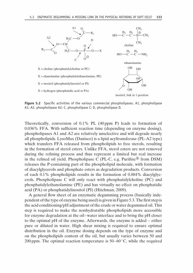
5.3 ENZYMATIC DEGUMMING: A MISSING LINK IN THE PHYSICAL REFINING OF SOFT OILS? 133
C
A2
A1
O
X = choline (phosphatidylcholine or PC)
ethanolamine
inositol, link in 1-position
choline
HO CH2
C NH2
H2
X = ehanolamine (phosphatidylethanolamine, PE)
X = inositol (phosphatidylinositol or PI)
X = hydrogen (phosphatidic acid or PA)
O
O O
−
XP
O D
C
OC
O
R1
O
CH
H2C
H2C
R2
HO CH2
C N
CH3
CH3
CH3
H2
OHOH
O
OH OH
OH
+
Figure 5.2 Specific activities of the various commercial phospholipases. A1, phospholipaseA1; A2, phospholipase A2; C, phospholipase C; D, phospholipase D.
Theoretically, conversion of 0.1% PL (40 ppm P) leads to formation of0.036% FFA. With sufficient reaction time (depending on enzyme dosing),phospholipases A1 and A2 are relatively unselective and will degrade nearlyall phospholipids. LysoMax (Danisco) is a lipid acyltransferase (PL-A2 type)which transfers FFA released from phospholipids to free sterols, resultingin the formation of sterol esters. Unlike FFA, sterol esters are not removedduring the refining process and thus represent a limited but real increasein the refined oil yield. Phospholipase C (PL-C, e.g. Purifine® from DSM)releases the P-containing part of the phospholipid molecule, with formationof diacylglycerols and phosphate esters as degradation products. Conversionof each 0.1% phospholipids results in the formation of 0.084% diacylglyc-erols. Phospholipase C will only react with phosphatidylcholine (PC) andphosphatidylethanolamine (PE) and has virtually no effect on phosphatidicacid (PA) or phosphatidylinositol (PI) (Hitchman, 2009).
A general flow sheet of an enzymatic degumming process (basically inde-pendent of the type of enzyme being used) is given in Figure 5.3. The first step isthe acid conditioning/pH adjustment of the crude or water degummed oil. Thisstep is required to make the nonhydratable phospholipids more accessiblefor enzyme degradation at the oil–water interface and to bring the pH closerto the optimal pH of the enzyme. Afterwards, the enzyme is added – eitherpure or diluted in water. High shear mixing is required to ensure optimaldistribution in the oil. Enzyme dosing depends on the type of enzyme andon the phospholipids content of the oil, but usually varies between 50 and200 ppm. The optimal reaction temperature is 50–60 ◦C, while the required

134 CH 5 EDIBLE OIL REFINING: CURRENT AND FUTURE TECHNOLOGIES
Steam
Deodorized Oil
Acid Caustic
Acid ReactionTank
DegummingCentrifuge
Enzyme
EnzymeReaction Tank
GUMS
Wash water
WashingCentrifuge
Water
ENZYMATICDEGUMMED
OIL
Steam
To storage
CRUDE OIL
Steam
Figure 5.3 Typical process flow diagram of a deep enzymatic degumming process. Courtesy of Desmet Ballestra.

5.3 ENZYMATIC DEGUMMING: A MISSING LINK IN THE PHYSICAL REFINING OF SOFT OILS? 135
reaction time mainly depends on the enzyme dosing. While in the past itwas common practice to apply a longer reaction time with a low enzymedosage (e.g. 30 ppm enzyme for 6 hours’ reaction), preference is now givento a shorter reaction time with higher enzyme dosage (e.g. 100 ppm enzymefor 2 hours’ reaction). This practice is preferred because it increases theflexibility of the process while keeping the operating (enzyme) cost at anacceptable level. Finally, the heavy phase (consisting of water and lyso gumsor phosphate esters) is separated by centrifugation from the degummed oil.
Two different types of enzymatic degumming can be distinguished: so-calledenzymatic water degumming and deep enzymatic degumming. Enzymaticwater degumming is typically applied in (soybean) crushing plants. Severallarge-capacity plants in South America (Argentina, Brazil etc.) are alreadyrunning in this mode. Increased oil yield is the main driver for its implemen-tation. The expected yield increase depends on the type of oil (P content) andthe type of enzyme used. The highest increase (up to 1.8%) can be expectedwhen crude soybean oil is enzymatically degummed with PL-C (Hitchmann,2009; Kellens, 2009); in this case, the oil yield increase is the sum of the dia-cylglycerols formed and the lower neutral oil entrainment in a smaller heavyphase (gums fraction). A lower yield increase (1.0–1.5%) will be obtainedfrom PL-C degumming of crude rapeseed oil or when phospholipase A1 or A2is used on crude soybean oil (Kellens, 2009). In the latter case, the net oil yieldincrease is due to the lower neutral oil entrainment in the gums fraction alone.
An increase in refined oil yield is obviously a very attractive featureof enzymatic (PL-C) water degumming, but by itself it is not enough tolead to implementation in all crushing plants. In the overall cost/benefitanalysis of the process, the enzyme cost and side-stream valorisation arealso taken into account. Depending on the value of (lyso-) lecithin, it maybe more profitable for a crusher to apply simple water degumming orenzymatic water degumming with PL-A1/PL-A2. The latter gives a lower netoil yield improvement compared to PL-C enzymatic degumming but yields alysolecithin side stream that may have value for specific applications.
PL-C enzymatic degummed soybean oil typically still has 100–150 ppmresidual P (mainly present in PA and PC). A significantly better degummingefficiency (P < 10 ppm) can be obtained when crude or water degummedvegetable oils are enzymatically degummed with commercial PL-A1 orPL-A2. This so-called ‘deep enzymatic degumming’ is already applied inseveral industrial plants. In addition to the increased oil yield, the very effi-cient phospholipid removal – making the degummed oil suitable for physicalrefining – is of great interest to refiners. As an alternative option, a combina-tion of PL-C and PL-A1/PL-A2 can be used for deep enzymatic degumming(Dayton, 2011; Galhardo & Dayton, 2012). The two enzymes can be addedeither separately or as a cocktail, depending on the plant design. Although thepotential advantages of the latter process are well described in the (patent)
136 CH 5 EDIBLE OIL REFINING: CURRENT AND FUTURE TECHNOLOGIES
literature (Dayton & Galhardo, 2008; Gramatikova et al., 2011), it is stillrarely applied on industrial scale.
A potential alternative to enzymatic degumming is the direct enzymaticdeoiling of the lecithin fraction resulting from the water degumming of crudeoils. In this patented process (De Greyt & Kellens, 2010), a phospholipase(e.g. Lecitase Ultra) is added to the wet lecithin and the phospholipids aredegraded into much less hydrophobic lysophospholipids. As a result, 80–90%of the entrapped neutral oil can be recovered by simple static decantationor centrifugation (Kellens, 2009; Kellens et al., 2010). The recovered neutraloil (FFA content: 25–30%) can be recycled to the crude or degummed oilor can be used as such as biodiesel feedstock, while the lysolecithin canbe added back to the deoiled meal. The main advantages of the enzymaticlecithin deoiling process over enzymatic degumming are the lower enzymeconsumption (∼50% less) and the fact that it is applied on a small side stream,with no impact on the oil degumming/refining process. The process has beentested successfully on a pilot scale but is currently not yet applied on anindustrial scale.
5.4 Bleaching: from single-stage colour removalto multistage adsorptive purification
Bleaching was introduced in edible oil refining at the end of the 19thcentury to improve the colour of cottonseed oil. Originally, it was a batchprocess at atmospheric pressure, in which natural bleaching clay was addedto hot oil with the sole objective of removing colouring pigments. Todaythis is no longer the case, and bleaching has become a critical process inedible oil refining. It has gradually turned from a single-stage ‘bleaching’into a multistage adsorptive purification process in which a wide rangeof unwanted components (soaps, phospholipids, oxidation products, tracemetals, contaminants etc.) are removed prior to deodorisation.
In order to reach this point, a whole series of process improvements wasgradually introduced, with the aim of reducing the overall processing costand improving the bleached oil quality. Vacuum bleaching was implementedfirst, in order to avoid oxidation and related colour fixation and improvethe oxidative stability. Later, as the capacity of refining plants increased,bleaching evolved from a batch to a (semi-) continuous process. This evolu-tion further improved the bleached oil quality and made the process moreenergy efficient. Another process improvement was the implementation of(horizontal/vertical) pressure leaf filters. Initially, plate and frame filters wereused, but these lost favour over the years due to the too high residual oilcontent in the spent bleaching earth (typically 35–40%) (Veldkamp, 2012).

5.4 BLEACHING 137
With pressure leaf filters, the residual oil content in the spent bleaching earthvaries between 25 and 30%, depending on the cake blowing efficiency.
Reducing oil losses in spent bleaching earth is very important as it willboth directly increase the bleached oil yield and reduce the quantity of spentbleaching earth that must be disposed of. In the past, spent bleaching earthstill had a certain value as it was sold mostly to the animal feed market.However, this practice became prohibited in a growing number of countriesdue to stricter feed safety regulations. Only in integrated crushing–refiningplants it is still possible to incorporate spent bleaching earth in the deoiledmeal. Refiners therefore have to look to other outlets for their spent bleachingearth. Some can dispose of it through biomethanisation, but for most disposalas landfill is the only (costly) option.
The increasing disposal costs, together with the oil losses in the spentbleaching earth, have a big impact on the overall operating cost of bleaching.The most efficient way of lowering the operating cost is to reduce thebleaching earth consumption. Much effort has been made to design moreefficient bleaching processes and develop more efficient bleaching clays andother specific adsorbents.
The bleaching earth efficiency can be significantly improved by acid acti-vation. Acid activation is carried out with H2SO4 or HCl. Its main effectis a significant increase in the specific surface area, by a factor of 3–6 to250–350 m2/g. Today, a wide range of acid-activated bleaching clays are com-mercially available from many (local) suppliers. This has resulted in a veryprice-competitive market, with products that are differentiated according todegree of activation, type of activation acid (H2SO4 or HCl) and particlesize distribution. The latter is an important and sometimes underestimatedcharacteristic as it greatly affects the filterability of the bleaching earth.
Although activated bleaching clays still have the highest market share,oil refiners are showing a growing interest in nonactivated bleaching earths,especially for the bleaching of palm oil. The main reason is the possiblecatalytic effect of highly (HCl) activated bleaching earths on the formationof potentially toxic 3-monochloropropane-diol (3-MCPD) esters during palmoil refining (De Greyt, 2012). This catalytic effect is not observed whennatural (or less activated) bleaching clays are used. Although the effect ofacid-activated bleaching earth on the formation of 3-MCPD esters is not yetfully understood and contradictory research data have been presented, it isclear that the growing demand for refined palm oil with low levels of 3-MCPDesters may have a serious impact on the palm oil refining process (De Greyt,2012; Ramli et al., 2011; Schurz, 2010). More specifically for the bleaching/drypretreatment process, it may result in the use of less strong acids and othergrades (more natural, less activated) of bleaching earth.
The active surface of bleaching earth can also be significantly improvedby a drastic reduction of its particle size (<10 μm). Such bleaching earths

138 CH 5 EDIBLE OIL REFINING: CURRENT AND FUTURE TECHNOLOGIES
can be produced, but the problem is that they cannot be separated fromthe oil by conventional filtration techniques. In order to overcome thisfiltration problem, the electrofiltration process was developed in the mid1990s (Transfeld, 1998). In this process, fine electrically charged particlesare agglomerated on an electrode at the end of the bleaching process andremoved via conventional filtration. The oil, being a nonconductive liquid,will not interfere in this process. Unfortunately, electrofiltration was onlytested on a pilot scale.
Bleaching earth consumption can also be reduced by increasing the effi-ciency of the bleaching process itself. Nowadays, bleaching is still mostlyoperated as a single-stage process, with only one bleaching reactor and onebleaching filter in operation. In such a process, the adsorption capacity ofbleaching earth is largely underutilised, and therefore multistage bleach-ing processes (multistage co-current, countercurrent, prefiltration over spentbleaching earth etc.) have been investigated. The least complicated multistagebleaching is the co-current process, with two (or more) bleaching reactors andthe same number of filters in operation. However, this only gives a limitedbleaching earth saving, which for most oils does not compensate for the extracapital investment required. More bleaching earth saving can be expectedfrom a countercurrent bleaching process. The first real countercurrent pro-cess was developed about 15 years ago by Ohmi Engineering (Transfeld &Schneider, 1996). This process features two bleaching reactors and two setsof filters. The spent bleaching clay of the second filtration is reused by mixingit back into the degummed/neutralised oil. Although bleaching earth savingsup to 40% are guaranteed, this countercurrent process is not widely applied,mainly because of its technical complexity. Another alternative is the ‘coun-tercurrent’ process in which the incoming oil is prefiltered over a filter loadedwith spent bleaching earth before fresh bleaching earth is added. Prefiltrationremoves all solid impurities and most of the phospholipids and soaps, whichincreases the bleaching earth efficiency in the bleacher. Typically, 10–15%bleaching earth can be saved in this way. Although savings are lower thanin the real countercurrent bleaching process, prefiltration is neverthelesspreferred by most refiners as it only requires one additional filter.
Removal of interfering components from the oil (e.g. phospholipids) priorto effective bleaching will also have a positive effect on bleaching earthconsumption. This is partially achieved by prefiltration, but can be done evenmore efficiently when silica hydrogels are used as an additional adsorbent.
Silica hydrogels (also named ‘silica’) are free-flowing white powders con-sisting of silicon dioxide (all or not acid activated) and high amounts of water(50–65%). These adsorbents have little or no affinity for (oil-soluble) colourpigments but are very efficient for the removal of polar impurities like phos-pholipids and soaps. Silica hydrogels were introduced in edible oil refining inthe mid 1980s (Taylor, 2004). Their first application was in chemical refining,

5.4 BLEACHING 139
where they were used for the removal of soaps, phospholipids and trace ele-ments as an alternative to the second washing (or sometimes even first soap)centrifuge. Today, this is still their main application in edible oil refining, butthey can also be used in (multistage) bleaching. Silica and bleaching earth canbe added to an oil together, but this has little or no beneficial effect as silicais only effective when applied at 70–80 ◦C and at atmospheric pressure (toavoid evaporation of the matrix water). A sequential addition of silica andbleaching earth is therefore more efficient. Silica (0.05–0.1%) is added firstto neutralised/degummed oil at 70–80 ◦C. After 15–30 minutes’ contact timeat atmospheric pressure, the oil–silica mixture can be sent either straight tothe bleacher or first to a separate drier. In the first, most straightforwardoption, silica and bleaching earth are removed from the oil on one filter. Abetter synergistic effect of silica and bleaching earth can be obtained whenthe oil–silica mixture is first dried and then transferred over a filter coatedwith spent bleaching earth (prefiltration with silica). This process (also knownas the Trisyl® Silica Tri-Clear process) claims a bleaching earth reductionof more than 40% when applied in the physical refining of rapeseed oil(Figure 5.4) (Jalalpoor, 2008). This lower consumption is partially due to theenhanced ability of the fresh bleaching earth to adsorb colouring pigmentsfrom the silica pretreated oil. In addition, use of silica seems to improvebleaching earth filterability, resulting in longer filter cycles and a higher pressbleach effect.
TRISYL® Silica
Incoming Oil/Fat
15 min, ca. 75 °CAtmospheric or low Vacuum
Dryer
Spent TRISYL® Silica/Clay
Discharging/Pre Coating
Pre-Filtration Post-FiltrationVacuum
Vacuum
Buffer Tank
Storage
or Bleacher
Figure 5.4 Schematic process diagram of the Trisyl® Silica Tri-Clear process. Published withthe courtesy of W. R. Grace & Co.

140 CH 5 EDIBLE OIL REFINING: CURRENT AND FUTURE TECHNOLOGIES
Another adsorbent that has long been used in the bleaching of edible oilsis activated carbon. This is produced from a carbon-rich material (nutshells,peat, wood, coal etc.), steam activated at a very high temperature (up to1000 ◦C) to give it its typical structure with a high surface area (up to1500 m2/g). The traditional use of activated carbon in edible oil refiningis in effective bleaching (colour removal), as a complementary (lipophilic)adsorbent to bleaching clay. However, as more efficient (activated) bleachingearths have become available, the use of activated carbon for bleachinghas been substantially reduced (Taylor, 2004). Today, activated carbon ismainly used for the removal of heavy polycyclic aromatic hydrocarbons(PAHs) from vegetable oils (coconut oil, palm kernel oil, olive pomace oiletc.) that have been contaminated by smoke drying or direct heating of theraw materials (De Greyt, 2010; Kemeny et al., 2011). At the end of the1990s, it was also introduced in fish oil refining for the adsorption of dioxinsand polychlorinated biphenyls (Maes et al., 2005). More recently, activatedcarbon treatment has begun to be applied more systematically as ‘best provenpractice’ for the decontamination of edible oils (like sunflower and rapeseedoil). This practice arose with the growing attention paid to the removal ofcontaminants from edible oils imposed by stricter legislation and driven bystricter trading specifications.
Activated carbon is still mostly added together with bleaching earth. If usedfor the removal of colour pigments, the bleaching earth–activated carbonratio is typically 80 : 20 or 90 : 10. Typical dosing for the removal of dioxin/PCBfrom fish oil is 1–3 kg/tonne, while for the removal of PAH from coconutoil it can be 5 kg/tonne or higher. The recent, more strict EU regulation onthe maximum allowable PAH content in vegetable oils will probably requirehigher dosing rates or even new, more efficient grades of activated carbon(Kemeny et al., 2011).
Apart from its higher cost compared to bleaching earth, the main disad-vantages of activated carbon are its higher oil retention and poor filtrationcharacteristics. To overcome the latter, activated carbon is mostly filteredtogether with bleaching earth. In some cases (e.g. decontamination of fishoil), this is however not possible as either no bleaching earth is used orrefiners want to keep the contaminated spent active carbon separate fromthe noncontaminated spent bleaching earth. For these applications, specialactivated carbon powders with improved filtration characteristics have beendeveloped. These so-called high filterability (HF) grades can be filtered withclassical pressure leaf filters or pulse tube filters, and membrane press filtersare also used. The latter allows squeezing of the spent activated carbon cakeat the end of the filtration cycle, which results in lower oil losses and areduction in spent cake (De Kock, 2006).
The possibility of removing specific colour bodies (e.g. chlorophyll) fromoils through enzymatic degradation has been under investigation for many

5.5 DEODORISATION 141
years. Recently, new developments in enzymatic bleaching were presented(Carlson et al., 2011). Chlorophyllases that can operate at pH 4.5–6.0 and at55–65 ◦C have been identified (Mikkelsen, 2011). When added during waterdegumming, these enzymes degrade chlorophyll components in canola andsoybean oil to very low residual levels (< 50 ppb), eliminating the need forbleaching earth addition (Carlson et al., 2011). An indicative enzyme costof US$3/tonne oil was mentioned, without further information on enzymestability and required dosing rate. This process was successfully tested at pilotscale but is not yet ready for implementation on an industrial scale.
By combining silica pretreatment, bleaching with prefiltration over spentbleaching earth and decontamination with activated carbon, bleaching effec-tively becomes a multistage modular adsorptive purification process. How-ever, the complete process is still rarely applied in industry. Not all refiners(need to) apply an activated carbon treatment, and if they do then it isstill mostly integrated in the effective bleaching step. Bleaching and activecarbon treatment are only separated when it brings significant advantagesfor the disposal costs of both solid waste streams. When applied separately,activated carbon treatment is best applied after bleaching. At the same time,the integration of silica pretreatment and/or prefiltration is not common prac-tice either. The (apparent) advantages of these additional steps (lower oillosses, lower disposal cost, less wastewater etc.) have to be weighed carefullyagainst the higher investment costs (additional equipment) and the additionalprocess steps and material handling. In efficient (chemical) refining plantsthat consistently obtain low phospholipids and low soaps after neutralisationor degumming, silica pretreatment or prefiltration may only give minimalcost savings. Although oil quality and sustainable processing are growing inimportance, in the end a potential cost saving remains the prime driver forthe implementation of a new process.
5.5 Deodorisation: much more than just aprocess for the removal of off-flavours
Deodorisation is usually the last stage of the refining process of edible oils.It was introduced at the end of the 19th century to improve the taste andsmell of refined oils. Today, the process is still commonly named ‘deodori-sation’, but the objectives have become much broader than just the removalof off-flavours. In fact, the current deodorisation process has three mainobjectives: (1) stripping of volatile components such as FFA (in the caseof physical refining), valuable minor components (tocpherols, sterols etc.)and contaminants (pesticides, light polycyclic aromatic hydrocarbons etc.);

142 CH 5 EDIBLE OIL REFINING: CURRENT AND FUTURE TECHNOLOGIES
(2) actual deodorisation by removal of different off-flavours; and (3) thermaldestruction of pigments (so-called heat bleaching).
Deodorisation is obviously a crucial refining stage with a big impact onthe refined oil quality. Apart from the desired effects, some unwantedside-reactions (like formation of trans fatty acids and polymeric triacylglyc-erols) may also occur during deodorisation. The effects of process conditions(temperature, time, pressure and stripping steam) on the standard qualityparameters and the nutritional quality of the refined oil are well understood(see Table 5.2) (De Greyt, 2010; De Kock & De Greyt, 2009), so deodoriserdesign and process conditions have been optimised to ensure minimal for-mation of trans fatty acids, maximal removal of volatile contaminants and acontrolled stripping of valuable minor components (tocopherols, sterols etc.).
New developments in deodorisation technology are driven by the contin-uous need for more efficient processes (lower operating cost, higher refinedoil yield and better valorisation of side streams) and the increased attentionpaid to the (nutritional) quality of food oils and fats. Recent trends anddevelopments are summarised in Table 5.3 (De Kock & De Greyt, 2009).As profit margins in edible oil deodorisation are small, further reduction ofthe operating cost has always been an important driver for new innovations.Fixed costs are primarily reduced by installation of higher capacity deodoris-ers. Today, single deodorisers with a capacity of more than 1500 tonnes perday have become more or less standard, especially for the deodorisation ofcommodity oils e.g. soybean oil, palm oil etc. Variable processing costs aremainly determined by energy consumption in the heating of the oil, genera-tion of the vacuum and production of the stripping steam. The introductionof optimised oil–oil heat exchangers in continuous deodorisers resulted ina higher heat recovery (up to 90%), giving a significantly reduced net fuelconsumption. Improved heat-recovery systems were also introduced in semi-continuous deodorisers. Installation of a double thermosyphon system givesa typical heat recovery of 65%, while the combination of one thermosyphonand the generation of low-pressure steam increases the heat recovery further,
Table 5.2 Effect of process variables on deodorised oil quality.
Quality parameter Temperature Time Pressure Steam
Taste + ++ + ++Colour (heat bleach) ++ + − −FFA stripping ++ − ++ +Trans fatty acid formation ++ ++ − −Tocopherol/sterol stripping ++ − ++ +Contaminant removala ++ − ++ +aPesticides, PAH, dioxins.−, little or no effect; +, significant effect; ++, large effect.

5.5 DEODORISATION 143
Table 5.3 Trends and developments in edible oil deodorisation.
Trend Development
Higher capacities >1500 tonnes per day, noexception
Higher energy efficiency Improved heat recoveryHigher stripping efficiency Improved tray design and
integration of packed columnsLower neutral oil losses Improved scrubber designLower heat load Application of dual-temperature
deodorisation and integration ofpacked column
Lower pressure Ice-condensing vacuum systems ofclosed loop with chilled water
Higher distillate value Application of dual condensation
to 75%. More efficient stripping steam distribution systems (special steam liftpumps) have been designed, and, for specific applications, packed columnsare integrated to improve stripping efficiency and reduce stripping steamconsumption.
Lowering the heat load (residence time at high temperature) during edi-ble oil deodorisation is another clear trend driven by the need to minimiseunwanted thermal degradation reactions and the desire for maximum reten-tion of the natural characteristics of an oil. Negative thermal effects duringdeodorisation can be minimised by the integration of packed columns (onlyfor dedicated purposes) or by application of dual-temperature deodorisers(Figure 5.5). These deodorisers operate at two different temperatures inorder to reach the best compromise between required residence time foractual deodorisation (longer time at lower temperature) and heat bleachingand stripping of volatile components (shorter time at higher temperature).The dual-temperature concept has been successfully introduced on an indus-trial scale. Both the low/high temperature and the high/low temperatureconcept can be applied.
In view of a further reduction of the heat load, the implementation ofmore powerful vacuum systems (chilled barometric vacuum system or dry-icecondensing) is important as it will allow a reduction of the deodorisationtemperature without affecting the stripping efficiency in a negative way. Mostconventional vacuum systems consist of a combination of steam ejectors(boosters), vapour condensers and mechanical (liquid-ring) vacuum pumps.These quite robust systems typically reach pressures in the deodoriser between2.5 and 5.0 mbar, but the motive steam consumption required to generatethe vacuum is high (up to 85% of the total steam consumption). Motivesteam consumption can be significantly reduced (by a factor of 2–3) by

144 CH 5 EDIBLE OIL REFINING: CURRENT AND FUTURE TECHNOLOGIES
CCW
Deodorizerdistillate
PACKEDSCRUBBER
To vacuumunit
HP steam
HP steam
PACKED COLUMNSTRIPPER
DEODORIZINGTRAYS
HEAT RECOVERYTRAYS
To vacuumunit
to final cooling,filtration and storage
Sparge steam
Cooling water
Bleached oil
Deodorized oil
Figure 5.5 Dual-temperature deodoriser with integrated packed column stripper. Courtesy ofDesmet Ballestra.

5.5 DEODORISATION 145
cooling the barometric condenser water. The benefit of a lower motive steamconsumption must be weighed against the extra chilling capacity (higherelectricity consumption) required to cool the barometric condenser water.Another benefit of using a chilled barometric vacuum system is a bettercondensation of the volatile matter, which gives a lower pressure in thedeodoriser (e.g. 1.5 mbar). These classical vacuum systems are increasinglybeing replaced by dry (ice) condensing systems (Figure 5.6). With suchsystems, the stripping steam is condensed on surface condensers operatingalternately at very low temperature (−30 ◦C). The efficient sublimation ofsteam and other volatile matter will give a very low pressure in the deodoriser(<1.5 mbar) and will strongly reduce odour emission. Dry–ice condensingsystems strongly reduce the motive steam consumption but require extraelectrical energy. Commercially available systems consist of two or morefreeze condensers with horizontally or vertically orientated straight tubes, arefrigeration plant for the generation of the cold refrigerant evaporated in
® ®
® ®
P1 T1
T1
Chiller
L1
TC
T1
DEODORIZERVAPOURS
ICE CONDENSER
WaterLoop
LP Steam
Fatty matter
To final vacuum
AmmoniaLoop
ICE CONDENSER
Clean coolingwater
Effluent
U
Figure 5.6 Typical process flow diagram of an ice condensing vacuum system. Courtesy ofDesmet Ballestra.

146 CH 5 EDIBLE OIL REFINING: CURRENT AND FUTURE TECHNOLOGIES
the tubes and a vessel for the defrosting and cleaning of the tubes after acertain period of freezing.
Design improvements are also introduced in the vapour scrubber system.The main objectives are a further reduction of the neutral oil losses (dueto mechanical entrainment) and an increase of the value of the deodoriserdistillate. Most deodorisers have only one vapour scrubber, from whichone single deodoriser distillate is collected. The amount and compositionof this side stream is determined by a number of factors, including theprocessed oil composition, the applied refining mode (chemical or physical)and the deodorisation conditions (Verleyen et al., 2001). Deodoriser distillatealways contains a certain amount of ‘neutral oil’ (triacylglycerols, partialacylglycerols etc.) which has been mechanically entrained from the oil. Thisrefining loss can be reduced by integration of a so-called ‘neutral oil recoverysystem’ (NORES) in the first part of the scrubber section. The purposeof this system is to recover the mechanical entrained neutral oil from thevapour phase before the volatile matter (FFA, tocopherols, sterols, odourcomponents, contaminants etc.) is effectively condensed. Deodoriser distillatefrom physical refining is characterised by a very high FFA content (>85%)and is mostly used for technical applications (oleochemistry). Recently, ithas also begun to be used as feedstock for biodiesel production (Echimet al., 2009). Deodoriser distillates from the chemical refining of vegetableoils (e.g. soybean oil) have a significantly higher added value, due to theirhigh concentration of valuable minor components such as tocopherols andsterols. Depending on the FFA content of the incoming oil and the amountof tocopherols stripped, a single scrubber can yield a deodoriser distillatecontaining 10–15% tocopherols (Table 5.4). The growing interest in anddemand for tocopherol-rich distillates (as a source of natural vitamin E) witheven higher tocopherol concentrations (up to 20%) has created a momentumfor the broader implementation of the so-called ‘double scrubber’. Thisconcept was already developed by the end of the 1990s, but has beencontinuously improved since (Figure 5.7). The vapour phase leaving thedeodoriser is first partially condensed at a higher temperature, giving a so-called ‘hot distillate’ in which the least volatile components (e.g. tocopherolsand sterols) are concentrated. Complete condensation of the remaining, morevolatile substances (mainly FFA) is then achieved in the second so-called ‘coldscrubber’, giving an FFA-rich ‘cold distillate’. Provided that the condensationtemperatures of the hot and cold scrubbers are properly set, this conceptgives a very good separation between the FFA and tocopherols. CombiningNORES with a double scrubber in the physical refining of soybean oil (forwhich processors seem to have a growing preference) gives a ‘hot distillate’with 21.2% tocopherols (Figure 5.8). Today, the commercial value of such adeodoriser distillate is high (>US$8000 per tonne), which corresponds to apotential extra revenue of US$15–25 per tonne of deodorised oil.

5.5 DEODORISATION 147
Table 5.4 Tocopherol concentration in soybeandeodoriser distillate from a single scrubber.
NB oila DB oilb
FFAs (% C18 : 1) 0.05 0.1 0.6Tocopherols (ppm) 1240 1200 1200
Fully refined oilFFAs (% C18 : 1) 0.015 <0.03 0.6Tocopherols (ppm) 900 511 515
Deodoriser distillateFFAs (% C18 : 1) 39.2 31.3 71.2Tocopherols (%) 20.4 16.2 6.9Yield (kg/ton) 1.23 3.6 8.52
aNeutralised, bleached soybean oil.bDegummed, bleached soybean oil.
Colddistillate
Coldscrubber
Hotscrubber
Final Heatingtray
To vacuumunit
Packed columnstripper
Hotdistillate
DOUBLE SCRUBBER sectionof a continuous deodorizer
Figure 5.7 Double scrubber for the selective condensation of FFA and tocopherols. Courtesyof Desmet Ballestra.

148 CH 5 EDIBLE OIL REFINING: CURRENT AND FUTURE TECHNOLOGIES
Degummed bleached soybean oil
0.61200
Deodorized soybean oil
Deodoriser distillate (single or double scrubber)
FFA (% C18:1)Tocopherols (ppm)
<0.03515
FFA (% C18:1)Tocopherols (ppm)
Single scrubber(One distillate)
Yield (kg/ton)Tocopherols (%)FFA (% C18:1)
8.526.971.2
Double scrubber (Hot distillate)
Yield (kg/ton)Tocopherols (%)FFA (% C18:1)
2.5218.214.8
Double scrubber +NORES (Hot distillate)
Yield (kg/ton)Tocopherols (%)FFA (% C18:1)
2.6621.239.0
Figure 5.8 Expected tocopherol concentration in deodoriser distillate from physical refiningof soybean oil (single- versus double-scrubber system). Courtesy of Desmet Ballestra.
5.6 Short-path distillation and supercriticalprocessing: refining technologies forthe future?
Short-path distillation is a well-known process that is characterised by theshort residence time of the product in the evaporator (<10 seconds) andthe very low operating pressure (<0.01 mbar). The incoming product flowsin a thin liquid film on a vertical cylinder (falling film evaporator) or on arotating surface (centrifugal film evaporator). The short distance (typically10–50 mm) between the internal condenser and the evaporator causes mini-mal pressure drop, which results in a very low operating pressure (Figure 5.9).Short-path distillation is especially suitable for the treatment/purification ofheat-sensitive products. It is established in lipid processing for the productionof high-purity monoacylglycerols and the concentration of omega-3 fatty acidsfrom fish oil (ethyl esters). It is also part of the downstream processing ofdeodoriser distillates for the concentration of tocopherols and sterols (Fabri-cius, 2009). Applications of short-path distillation in edible oil refining arestill scarce. At the end of the 1990s, it was introduced on an industrial scale forthe production of red palm oil (rich in carotenoids). However, as investmentand operating costs are high, it never became broadly implemented. Morerecently, a short-path distillation process was developed for the removal ofcontaminants from fish oil (Oterhals et al., 2010). This has been successfullyapplied by a limited number of fish oil processors, who prefer it over themore broadly implemented combined active carbon treatment/low-pressurestripping (Maes et al., 2010). Finally, short-path distillation can also be used

5.6 SHORT-PATH DISTILLATION AND SUPERCRITICAL PROCESSING 149
1
(1) Feed product(2) Concentrate (residue)(3) Distillate(4) Vacuum(5) Heating medium(6) Cooling water
(A) Heating jacket(B) Internal condenser(C) Rotor
5
2
3
4
C
B
A
6
Figure 5.9 Schematic view of a short path evaporator. Courtesy of Buss-SMS-Canzler GmbH.
for efficient FFA stripping at low temperatures (<200 ◦C), which makes itan interesting process for the physical refining of heat-sensitive oils (fish oil,algae oil etc.). These oils are still mostly chemically refined, since completeFFA removal without significant degradation of the omega-3 fatty acids isvery difficult to achieve using classical stripping technology. However, it hasto be emphasised that short-path distillation is not an effective ‘deodorising’process. As with packed column stripping, the residence time is much tooshort to produce a stable, odourless and bland refined oil: for fish oil inparticular, this requires a long ‘deodorisation’ time of several (2–4) hours atmoderate temperature (<190 ◦C), with the injection of sufficient sparge steam,which can still best be achieved in a ‘classical’ batch or (semi-) continuousdeodoriser.
Supercritical CO2 processing is another technology that has been investi-gated for use in edible oil refining. It was tested successfully at laboratoryscale some years ago for the degumming of crude soybean oil (List et al.,1993), the deacidification of rice bran oil (Dunford & King, 2001) and the mildrefining of palm oil (Ooi, 1996). Nevertheless, it has never been industriallyapplied, due to the high investment and operating costs involved, which makeit commercially viable only for high-value products.

150 CH 5 EDIBLE OIL REFINING: CURRENT AND FUTURE TECHNOLOGIES
ReferencesCarlson K., Mikelsen R. & Soe J.B. (2011) New approaches for chlorophyll removal in oil
processing. Paper presented at the 102nd AOCS Annual Meeting and Expo, Cincinnati,OH, USA.
Clausen, K. (2001) Enzymatic oil degumming by a novel microbial phospholipase. Eur. J.Lipid Sci. Technol., 103, 333–340.
Cogate, P. (2010) Cavitational reactors for process intensification of chemical processingapplications: a criticial review. Chemical Engineering and Processing, 47, 515–527.
Dayton, C. (2011) Enzymatic degumming for physical refining. Paper presented at the SCIworkshop on enzymatic processing and modifications, Ghent, Belgium.
Dayton, C. & Galhardo, F. (2008) US patent application 2008/0182322.De Greyt, W. (2010) Developments in edible oil refining for the production of high quality,
contaminant-free food oils. Proceedings of the POMREQ Conference, Kota Kinabalu,pp. 147–156.
De Greyt, W. (2012) How to minimize 3-MCPD and glycidyl esters during oil processing.Paper presented at the 103rd AOCS Annual Meeting and Expo, Long Beach, CA, USA.
De Greyt, W. & Kellens, M. (2010) US patent 7 696 369.De Kock, J. (2006) Technologies for cleaning oils and meals. Paper presented at the
EWOS workshop, Byrkjedalstunet, Norway.De Kock, J. & De Greyt, W. (2009) Recent developments in edible oil deodorization.
Paper presented at the 7th EuroFedLipid conference, Graz, Austria.Deffense, E. (2002) US patent 6 407 271.Dunford, N. & King, J. (2001) Thermal gradient deacidification of crude rice bran oil
utilizing supercritical carbon dioxide. J. Am. Oil Chem. Soc., 78, 121–125.Echim C., Verhe, R., De Greyt, W. & Stevens, C. (2009) Production of biodiesel from
side-stream refining products. Energy Environ. Sci., 2, 1131–1141.Fabricius, R. (2009) Applications of short path evaporators in the oils and fats and
oleochemical industry. Paper presented at the 28th ISF Congress, Sydney, Australia.FAOSTAT (2012) Edible oil production volumes. Available from http://faostat.fao.org,
last accessed 8 January 2013.Galhardo, F. & Dayton, C. (2012) Enzymatic degumming. AOCS Lipid Library, avail-
able from http://lipidlibrary.aocs.org/processing/degum-enz/index.htm, last accessed 8January 2013.
Gramatikova, S., Hazlewood, G., Lam, D. & Barton, N.R. (2011) US patent 7 977 080.Hernandez, E. & Rathbone, S.J. (2002) US patent 6 448 423.Hitchman, T. (2009) Purifine® PLC: industrial application in oil degumming and refining.
Oil Mill Gazetteer, 115, 2–4.Jalalpoor, M. (2008) PCT patent application, 2008/02552 A2.Kellens, M. (2009) Oil processing challenges in the 21st century: enzymes key to quality
and profitability. Paper presented at the 28th ISF Congress, Sydney, Australia.Kellens, M., De Greyt, W., Kemper, T. & Willits, J. (2010) Enzymatic oil processing:
current status and future developments. Paper presented at the 101st AOCS AnnualMeeting and Expo, Phoenix, AZ, USA.
Kemeny, Z., Hellner, G., Radnoti, A. & Ergomoa, T. (2011) Polycyclic aromatic hydro-carbon removal from coconut oil. Paper presented at the 9th EuroFedLipid conference,Rotterdam, Netherlands.
Lin, L. & Koseoglu, S.K. (2004) Membrane processing of fats and oils. In: F. Shahidi(ed.) Bailey’s Industrial Oil and Fat Poducts, Volume V. New York, NY, USA: WileyInterscience, pp. 437–457.

REFERENCES 151
List, G., King, J., Johnson, J., Warner, K. & Mounts, T. (1993) Supercritical CO2degumming and physical refining of soybean oil. J. Am. Oil Chem. Soc., 70, 473ff.
Maes, J., De Meulenaer, B., Van Heerswynghels, P., De Greyt, W., Eppe, G., De Pauw, G.& Huyghebaert, A. (2005) Removal of dioxins and PCB from fish oils by activatedcarbon treatment. J. Am. Oil Chem. Soc., 82, 593–597.
Maes, J., Vila Ayala, J., De Meulenaer, B., Verhe, R., Gibon, V. & De Greyt, W. (2010)Process optimization for the removal of environmental contaminants from fish oils.Oleagineux Corps gras Lipides, 17, 81–85.
Meyers, H. (2000) US patent 6 111 120.Mielke, T. (2011) Rapidly increasing global dependence on rapeseed/canola and oil. Paper
presented at the 15th International Rapeseed Congress, Prague, Czech Republic.Mikkelsen, R. (2011) Biotechnological approaches to remove chlorophyll components in
plant oils. Paper presented at the 102nd AOCS Annual Meeting and Expo, Cincinnati,OH, USA.
Moulton, K.J. & Mounts, T.L. (1990) Continuous ultrasonic degumming of crude soybeanoil. J. Am. Oil Chem. Soc., 69, 443–446.
Ooi, C. (1996) Continuous supercritical carbon dioxide processing of palm oil. J. Am. OilChem. Soc., 73, 233–237.
Oterhals, A., Kvamme, B. & Berntssen, M. (2010) Modelling of a short-path distillationprocess to remove persistent organic pollutants in fish oil based on process parametersand quantitative structure properties relationships. Chemosphere, 80, 83–92.
Ramli, M.R., Siew, W.L., Ibrahim, N.A., Hussein, R., Kuntom, A., Razak, R. & Nesaret-nam, K. (2011) Effects of degumming and bleaching on 3-MCPD esters formation duringphysical refining. J. Am. Oil Chem. Soc., 88, 1839–1844.
Schurz, K. (2010) Development of the bleaching process under the perspective of classicand new applications. Paper presented at the 3rd DGF Symposium, Leipzig, Germany.
Svenson, E. & Willits, J. (2012) Nano-neutralization™. In: W.E. Farr & A. Proctor (eds)Green Vegetable Oil Processing. Champaign, IL, USA: AOCS Press, pp. 157–168.
Taylor, D.R. (2004) Bleaching. In: F. Shahidi (ed.) Bailey’s Industrial Oil and Fat Poducts,Volume 5. New York, NY, USA: Wiley Interscience, pp. 285–339.
Transfeld, P. (1998) Electrofiltration cuts bleaching earth use. INFORM, 9, 502–506.Transfeld, P. & Schneider, M. (1996) Countercurrent system cuts bleaching costs.
INFORM, 7, 756–767.Veldkamp, F. (2012) From fundamentals to new filter technologies. Paper presented at
the Edible Oil Refining Update short course at the 103rd AOCS Annual Meeting andExpo, Long Beach, CA, USA.
Verleyen, T., Verhe, R., Garcia, L., Huyghebaert, A., Dewettinck, K. & De Greyt, W.(2001) Gas chromatographic characterization of vegetable oil deodorization distillate.Journal Chromatography A, 921, 277–285.

6Oil Modification ProcessesMarc Kellens1 and Gijs Calliauw2
1Group Technical Director, Desmet Ballestra Oils and Fats, Zaventem, Belgium2Development Manager Modification, Desmet Ballestra Oils and Fats, Zaventem,Belgium
6.1 IntroductionAll oil modification processes involve a substantial change of the physicalbehaviours and structural properties of an oil. This differentiates the modifi-cation processes from the refinery processes discussed in Chapter 5, in whichthe processing effect is more orientated towards improved organoleptic prop-erties and nutritional value. There are three main modification technologiesavailable in the edible oils industry at present: hydrogenation (reducing thedegree of unsaturation on the acyl chains), interesterification (intermolecularredistribution of the acyl groups on the glycerol backbone) and fractionation(a fractional crystallisation of the oil, followed by a phase separation).
The drive for healthier edible oil products has substantially changed theface of the modification technologies as they were originally conceived in the20th century. The use of catalysts, solvents and chemicals, which is in anycase preferably kept to a minimum for simple cost reasons, is increasinglybeing discouraged due to these compounds’ possible harmful and pollutingeffects. Moreover, the formation of undesirable side products – undesirablein terms of their health effects – such as the trans fatty acids, or more recentlythe monochloropropanediol (MCPD)-esters during deodorisation, has led toa complete rethinking or even total abandonment of well-established, provenindustrial practices, as they are being traded for ‘greener’, more sustainableand healthier technologies.
Edible Oil Processing, Second Edition. Edited by Wolf Hamm, Richard J. Hamilton and Gijs Calliauw.© 2013 John Wiley & Sons, Ltd. Published 2013 by John Wiley & Sons, Ltd.

154 CH 6 OIL MODIFICATION PROCESSES
6.2 Hydrogenation6.2.1 Historical perspectiveThe Nobel Prize winner Paul Sabatier was the first to work out the hydro-genation chemistry of volatile triglycerides, in the 1890s. Shortly after that,Wilhelm Normann demonstrated that the same principle could be applied toliquid oils. He filed several patents on the matter in 1902 and 1903 (Normann,1903), and promptly built a hardening factory with his acquired knowledge.So, although technically the patenting of catalytic hydrogenation on oil waspreceded by a fractionation patent a good 30 years earlier, hydrogenation wasthe first process to be applied globally on an industrial scale. It can thereforebe considered the oldest of the three main oil modification technologies, forin both Europe and the USA, hydrogenation was already commercialisedbefore the First World War.
Originally, hydrogenation of edible oils was mainly used to improve theoxidative stability of oils that contained multiple polyunsaturated fatty acids,such as fish oil. The high susceptibility of these oils to air oxidation, especiallywhen heated, made them unusable in a lot of food applications (particularlythose involving baking and frying). Furthermore, oxidation reduces shelf lifeas it triggers the formation of off-flavours upon storage. The practice ofhydrogenation therefore allowed liquid oils to be stored for much longer thannature would normally permit.
The reduction of unsaturation of the oil also leads to a considerable increasein melting point and thus an increasing transformation of the oil into fat. Thistechnique therefore facilitates the processing of natural oils into tailormadeproducts with specifically desired properties: a selective and partial hydro-genation of edible oil will result in a stable but still pourable liquid oilsuitable for cooking, whereas a more complete hydrogenation enables theproduction of brittle, high-melting fats for use as coatings, spreads and soon. The first successful hydrogenated products on the market were short-enings made from cottonseed oil. This also shows that, certainly in theearly days, the introduction of hydrogenation in oil processing made thesourcing of oil with specific physical behaviour a less crucial issue, sincethis process was able to turn even the most polyunsaturated oil into a fatthat could even be as hard as candle wax in a matter of hours. Hydro-genation has steadily developed since, due to increasing understanding ofhydrogenation effects, reaction control and, not least, catalyst optimisation.But as the nutritional and health aspects of edible oil consumption beganto receive more attention in the 1970s and 1980s, hydrogenation becameidentified as a major source of not just saturated but also trans fatty acidsin the human diet. The latter are commonly (but not unanimously) believedto raise low-density lipoprotein (LDL) blood levels and increase the risk

6.2 HYDROGENATION 155
of coronary heart disease (Mensink et al., 1992). Despite the controversyaround this subject and the sometimes contradictory results from variousmedical studies, it has led to a general push for reduction, explicit labellingand even elimination of trans fatty acids in food. It is not within the scopeof this chapter to elaborate upon this multifaceted topic, but the reviewof the position of trans fatty acids and their impact on our food formula-tion (and hydrogenation) by List et al. (2007) is highly recommended. The‘unhealthy’ reputation of hydrogenation technology has had an undeniableimpact on the global hydrogenation capacity. Where it was estimated inthe mid 1990s that about 90% of all edible oils passed through hydrogena-tion (which for soft oils alone would amount to about 35 million tonnes), 1decade later only 6 million tonnes of oils were hydrogenated annually (Beerset al., 2008).
6.2.2 PrincipleThe general hydrogenation reaction consists in a sequence of reactions thatallow the net adding of protons (hydrogen atoms) to a fatty acid chain.
Although the basic reaction of adding hydrogen to a double bond is quitestraightforward, it is not a pure reaction, and different types of reaction canoccur when a fatty acid chain (with double bond) adsorbs to the catalystsurface and dissociated hydrogen is present. The first hydrogen can add tothe double bond, and if another hydrogen atom can be added then the resultis an irreversible, stable, saturated C-C bond, which desorbs from the catalystsurface (saturation). This ‘other’ hydrogen atom, however, can also be anH-atom on the neighbouring C-atom, which results in a shifting of the doublebond down the fatty acid chain (positional isomerism). This isomerisation haslittle impact on the physical behaviour of the oil. At the moment of additionof the first hydrogen atom and the existence of the ‘half-hydrogenated’intermediate (Beers et al., 2008), the sp3-orbital momentarily allows freerotation over the C-C axis. It is exactly this sort of brief ‘randomness’ thatpermits formation of trans fatty acids (geometrical isomerisation). Thesedifferent outcomes of adding hydrogen to a double bond were presented inthe 1950s.
It is crucial to understand that there does exist a competition between thesereactions: saturation versus isomerisation. Dijkstra (2010) has publishedvarious reviews of the reaction mechanism in edible oil hydrogenation, inwhich the different steps of the complex reaction are discussed, especially interms of the order and rate of each subreaction. Indeed, in ideal conditions,the hydrogenation of a polyunsaturated fatty acid actually occurs stepwise.Essentially, for each of these subreactions, the competition between the twotypes of reaction can be reduced to a balance between hydrogen demand
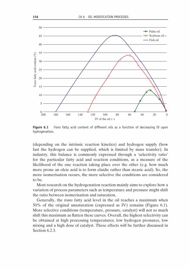
156 CH 6 OIL MODIFICATION PROCESSES
50Palm oilSoybean oil
Fish oil45
40
35
30
Tra
ns f
atty
aci
d co
nten
t (%
)
25
20
15
10
5
0200 180 160 140 120 100
IV of the oil (−)
80 60 40 20 0
Figure 6.1 Trans fatty acid content of different oils as a function of decreasing IV uponhydrogenation.
(depending on the intrinsic reaction kinetics) and hydrogen supply (howfast the hydrogen can be supplied, which is limited by mass transfer). Inindustry, this balance is commonly expressed through a ‘selectivity ratio’for the particular fatty acid and reaction conditions, as a measure of thelikelihood of the one reaction taking place over the other (e.g. how muchmore prone an oleic acid is to form elaidic rather than stearic acid). So, themore isomerisation occurs, the more selective the conditions are consideredto be.
Most research on the hydrogenation reaction mainly aims to explore how avariation of process parameters such as temperature and pressure might shiftthe ratio between isomerisation and saturation.
Generally, the trans fatty acid level in the oil reaches a maximum when50% of the original unsaturation (expressed as IV) remains (Figure 6.1).More selective conditions (temperature, pressure, catalyst) will not so muchshift this maximum as flatten these curves. Overall, the highest selectivity canbe obtained at high processing temperatures, low hydrogen pressures, lowmixing and a high dose of catalyst. These effects will be further discussed inSection 6.2.3.

6.2 HYDROGENATION 157
6.2.3 Process parameters6.2.3.1 Hydrogen pressureOverall, a higher pressure of hydrogen gas will shift the reaction towardssaturation, since in this case the hydrogen reagent is available to a virtu-ally unlimited extent for the partially hydrogenated intermediate and so agreater chance exists that a second hydrogen atom will be added beforethe free rotation over the C-C axis makes it possible for geometrical iso-merism to take place. However, not only is the trans isomerisation reducedby the higher hydrogen concentrations but the selectivity of the reactionalso drops (due to the difference in reaction order for different degrees ofunsaturation). It should be noted that for a reduction of 50% of the ‘nor-mal’ trans content in a partially hydrogenated rapeseed oil (e.g. from 40 to20%), hydrogen pressures over 40 barg should be applied in high-pressurereactors. Increased hydrogen pressures are therefore helpful in reducingtrans fatty acid formation. However, this practice does not result in a fullelimination of trans fatty acids, and can generate undesired high amounts offully saturated triglycerides, which limit the possible applications for such fats(List et al., 2007).
6.2.3.2 TemperatureAs for many chemical reactions, the rate of the reaction increases substantiallywith increasing temperature, so hydrogen atoms near the absorbed doublebond will react faster with the double bond. Under these conditions, thereaction interface is virtually instantly depleted of hydrogen. Therefore,with increasing temperature, the supply of hydrogen towards the catalystreaction surface will eventually be the limiting factor of the reaction. As theisomerisation reaction has a lower-order dependency on hydrogen than thehydrogenation reaction, increasing temperature will boost the selectivity butalso the trans formation. In recent years, the trend has been mainly to lowerthe operation temperatures, resulting in a significant trans reduction but alsoa lower capacity (Figure 6.2).
6.2.3.3 CatalystThe archetypal catalyst in hydrogenation is reduced nickel (Ni) supported onnatural earth, such as kieselguhr. These supports have a high surface–volumeratio, which is an evident asset for adsorption processes. The high porosityadditionally permits swift mass transfer from and to the bulk phase. Thepowder, about 2–12 μm mean particle size, is commonly formulated in soliddroplets of hard fat such as palm stearin or fully hydrogenated oil, in order toprevent the Ni from oxidising and to facilitate handling and dosing.

158 CH 6 OIL MODIFICATION PROCESSES
40
35
30
110 °C-20 barg-100 ppm Ni
120 °C-20 barg-100 ppm Ni
180 °C-3 barg-100 ppm Ni
25
20
15
Tra
ns f
atty
aci
d co
nten
t (%
)
10
5
0140 120 100 80 60 40 20 0
IV of the oil (−)
Figure 6.2 Trans fatty acid content at different temperatures and hydrogen pressures as afunction of decreasing IV upon hydrogenation.
The type and concentration of the catalyst chosen is quite dependenton the purpose of hydrogenation: if an increased oxidative stability of theliquid oil is intended, a high selectivity towards polyunsaturated fatty acids ispreferred. A good catalyst selection can help steer a reaction towards more orless trans formation, although this is mainly true for nonselective conditionssuch as high hydrogen pressures. As soon as hydrogen becomes the limitingreagent (through increased temperature, lower pressure or increased catalystconcentration), the catalyst type itself has very little impact on the (large)quantity of trans isomers formed.
Using spent catalyst or poisoning it with sulfur will favour trans-isomerisation. This is because upon reuse (or with insufficient refining in thepreceding bleaching and deodorisation section) the catalyst will lose activityand/or selectivity due to absorbed impurities such as sulfur and phosphorus.Nickel sulfides will affect the dissociation of the hydrogen molecules in sucha way that less hydrogen is available for saturation, and therefore the rateof (trans) isomerisation will considerably increase. The inverse is also true:some manufacturers aiming for the lowest possible trans content prefer to

6.2 HYDROGENATION 159
dose the catalyst in multiple stages, in an attempt to use only the freshest andmost active of all catalysts and minimise side reactions due to impurities.Alternatively, sometimes spent catalyst is added prior to hydrogenation inorder to absorb the impurities, and then filtered from the oil. This is a way ofcleaning the oil of sulfur or phosphatides. Such phosphorus compounds, evenat concentrations as low as 4 ppm, can physically occupy the inner channelsof the catalyst, restricting the adsorption surface.
Many other catalysts have been investigated, among which the noble metalsprobably represent the most relevant alternative to standard nickel catalyst,due to their superior catalytic activity at – interestingly – lower temperatures.Although the use of alternative catalysts for edible oil hydrogenation is by nomeans novel, this topic will be discussed in the following sections on recentdevelopments.
6.2.4 Process designIn essence, a hydrogenation plant requires a heating system, a properlydesigned reactor and a post-process filter system to recover the spent catalyst(Figure 6.3).
Hydrogenation is exothermic, and each drop in iodine value can cause anoil temperature increase of about 1.7 ◦C. Most industrial designs are thereforeprovided with cooling/heat recuperation.
The plant usually operates batchwise, although the integration of variousbuffer tanks can lead to a more continuous form of operation. Continuousreactors have also been designed.
Before entering the reactor and mixing with hydrogen, the fresh oil is deaer-ated and dried in a buffer tank kept under reduced pressure. The incoming oilis sprayed in a thin film on a coil in which the previously hydrogenated batchof oil circulates, for heat-recovery reasons. The temperature of the incomingoil then rises from 50 to about 150 ◦C for hydrogenation pressures up to 6 bargand to about 90 ◦C for hydrogenation pressures >10 barg.
As soon as the reactor is filled with the oil, the catalyst is added, and themixture is then brought to vacuum conditions. Only then is a controlled flow ofhydrogen introduced, according to the hydrogenation pressure requirement.A typical batch reactor is usually equipped with an agitator, not only tokeep the catalyst in suspension but also to create a good dispersion of theintroduced hydrogen bubbles (which is also a function of the position andtype of spray nozzles used) and thus to provide intense mixing of all reagents.
A well designed agitator serves multiples purposes: it should disperse thebubbles properly through the bulk, recirculate the overstoichometric gasexcess and homogenise the (more viscous) oil phase to ensure the requiredmass transfer. The straightforward parameter used to assess the performance

160 CH 6 OIL MODIFICATION PROCESSES
HYDROGEN
OIL INLET
Feed Tank
Drop Tank
BatchHydrogenation
Reactor
CoolingSystem
Buffer Tank
Deaearation/Heat recovery
VacuumGroup
Filtration
Safety &PolishingFiltration
Nitrogen
FIC
LICA LA
S
LA
S
TIC
TIC
TI
TI
R
FIC
LP steam
Coolingwater in
Coolingwater out
TICA
LICA
TI
LS
FIC
HP Steam
Nitrogen
Nitrogen
Nitrogen
Nitrogen
Coolingwater in
Coolingwater out
SPENT CATALYST
TO POST-TREATMENT
Atm. above roof
PS
TI
Barometric waterSteam Steam
TITI
PI
HP Steam
LP Steam
LS
CATALYST
FIC
PIC
LAS
LAS
LP Steam
LP Steam
PI PI
PI
LAS
TI
TI
PI
PI
PI
PI
PI
PI
PI
PIA
PI
PI
R
RR
R
R
PIA
PI
PI
to cooling tower
Clean water
HYDROGENATEDOIL TO STORAGE
TI
TI
TIC
TIC
R
PI
PI
TI
Figure 6.3 Schematic process diagram of hydrogenation.

6.2 HYDROGENATION 161
of a reactor design is the rate of hydrogen uptake, rH , expressed in mol/m3.s,which can be calculated thus (Koetsier, 1997):
rH = kL • a • �CH (6.1)
where kL is the mass transfer coefficient in quiescent liquid (m/s), a is thespecific air–oil interface area (m2/m3) and �CH (mol/m3) is the concentrationdifference of hydrogen at the interface and the bulk oil, which is the actualdriving force of uptake into the oil. It is clear that the specific area parameter,and thus the overall hydrogen uptake in the reactor, will be greatly affected byhow well the agitator manages to break up the introduced hydrogen bubblesinto microscopic bubbles.
Another reactor type used for industrial hydrogenation is a loop reactor, inwhich the suspension is recirculated at high velocity through a mixing nozzlewhile hydrogen is introduced. The two main benefits of this type of reactorare the absence of mechanical agitation and that the hydrogen bubbles act asa stripping agent for moisture and oxygen left in the oil, making a precedingdrying step and vacuum conditions redundant. In practice, however, it appearsto be difficult to obtain rH rates comparable to those of a dead-end batchreactor, because of the lower specific interfacial area created. In certainreactions, the higher degree of side reactions such as oxidation and hydrolysisdue to the presence of oxygen and moisture can present an additional qualityissue, nullifying the original advantage of a loop reactor.
Since the hydrogenation reaction is highly exothermic, the heat generatedby the reaction itself can be used to reach the optimal reaction temperatureat first (∼180 ◦C for hydrogenation pressures up to 6 barg and ∼120 ◦C forpressures above 10 barg). There are several systems available to subsequentlyrecover the excess heat, such as steam/hot water production through thepumping of soft water through a coil or internal heat exchanger inside thereactor. Once the optimal reaction temperature is reached, the IV shoulddrop by 0.5 to 3 units per minute. This means that the reactor should be able toreject the still-developing heat, as without cooling, the oil temperature wouldkeep on rising at about 5 ◦C every minute. At elevated hydrogen pressures(20–25 barg), the hydrogenation reaction will proceed considerably faster; upto twice as many batches can be processed on a daily basis using elevated ascompared to normal hydrogen pressures (3–5 barg).
In the case of partial hydrogenation, the reaction simply ends when thesupply of gas is discontinued. The hydrogen should be dosed with greataccuracy in order to obtain consistent production. For full hydrogenation,it is obviously the scarcity of double bonds left in the oil that will finallyslow the reaction. The process can be steered sufficiently in terms of time,temperature and so on in the light of the desired end product quality anddegree of hardening (Tables 6.1 and 6.2).

162 CH 6 OIL MODIFICATION PROCESSES
Table 6.1 Typical reaction times for hydrogenation pressures up to 6 barg (dead-end reactor,INTERMIG agitator).
Oil type �IV Final IV Reaction time (h) Number ofcycles per day
Soybean, sunflower 10–25 >100 <1 ∼15Soybean, sunflower max. 50 >70 1.5 10Soybean, sunflower max. 60 70 2.5 8Palm oil 10–20 >30 2 10Palm oil max. 50 <2 4 5
Table 6.2 Typical process parameter variation for different hydrogenated products (fromsoybean oil).
Characteristic Brush Shortening Margarine Coating Stearin
IV 115 75 70 75 <5Trans isomers (%) 15 30 50 65 –C18 : 0
absolute (%) 5 9 7 7 85increase (%) 1 5 3 3 80
Temperature (◦C) 170 150 210 210 220Time (min) 30 60 60 60 300–150H2 pressure (bar) 1 2 1 2 max.Catalyst type selective selective/nonselect selective Ni-S high activeNi (ppm) 50 100 100 500–1000 500–1500
The hydrogenated oil batch is then dropped into a tank under reducedpressure. This vessel is also equipped with an agitator to prevent settling ofthe catalyst. Cooling to the required filtration temperature is carried out bymeans of heat exchange with fresh cold oil circulated through the coils ofthe reactor. If needed, an additional cooling is performed in the safety oilcooler. The cooled oil is collected in an oil buffer tank, from where it is sent tofiltration over – typically – a back-pulse filter (such as leaf or candle filters).For plants that operate many stock changes, a simple plate-and-frame filtermight still be preferred, in order to reduce possible contamination in the heelvolume. After the filtration, the nickel concentration in the hydrogenated oilshould be below 5 ppm and preferably not greater than 1 ppm
The drying of the spent catalyst cake is carried out by nitrogen blowing, andthe thus recovered oil and heel volume of the filter can be recirculated, whilethe dried cake is discharged by nitrogen pulses through a filter cake hopperto the disposal container. The performance of the filter then determines towhat extent the catalyst can be reused. Some processors prefer to install anadditional safety filter and oil cooler prior to sending the hydrogenated fatto the tank farm.

6.2 HYDROGENATION 163
6.2.5 Future for hydrogenation technologyMost advances and research in recent years have been dedicated to reducingtrans fatty acids without sacrificing the high selectivity of the reaction.
6.2.5.1 Smarter combinations of the conventional technologyIn recent years, the boundaries of trans reduction in classic technology havebeen explored by combining higher pressures (5–15 barg) and extremely lowtemperatures (such as in the Losatra® process, with operating temperaturesbetween 40 and 50 ◦C). Effectively, the setup could lower the trans contentin soybean oil IV 100 to a mere 5%. Typically, such processes require highcatalyst dosage (>1500 ppm Ni), however, and are noted for their very slowconversion rates, in the order of 0.2–0.4 IV drop/minute.
In a different set of experiments, similar low temperatures were combinedwith adapted Ni catalyst. These too have shown a reduced trans level: aslow as 6%. There are considerable downsides to this practice, mainly dueto the reduced catalyst activity and consequently long reaction times (Beerset al., 2008).
6.2.5.2 Alternative catalystsMuch research effort has been invested in catalyst optimisation. Nickel isnevertheless still the archetypal catalyst. In terms of selectivity, the preciousmetal palladium (Pd) probably has the performance closest to typical nickelcatalyst results for partial hydrogenations. Rhodium (Rh)-based catalystsshow results shifting to higher saturation over trans formation ratios, but thebest values in this respect are obtained by platinum (Pt) catalysts (Table 6.3).
This comes at the expense of fairly increased saturate levels, and conse-quently flat (as in ‘unsteep’) melting behaviour and excessive waxiness atelevated temperatures are observed in the resulting fat products. Effectively,the presence of trans fatty acids is often a means of having steeper meltingcurves, and these products are, from a functional point of view, generallypreferred over the softer and/or flatter low-trans alternatives.
Copper catalysts and homogenous metal complexes have also been studiedover the years. In some cases, these studies have demonstrated results at theother end of the spectrum: fats with over 60% trans fats are no exception.
In terms of the applicability of these alternative catalysts, it is good torealise that many require deviating (often more demanding, and thus moreexpensive) reaction conditions compared to those usually applied when usingnickel catalysts. This severely limits the practicality of these catalysts in thecommon hydrogenation technology for edible oils. A second and equallyimportant disadvantage is their cost: they require a very large emphasis oncatalyst recovery and reuse, and often the value added to the fat products(which are often considered commodity fats with low added value) does not

164 CH 6 OIL MODIFICATION PROCESSES
Table 6.3 Effect of nickel versus platinum catalyst on fatty acidcomposition and solid fat content (SFC, %) of soybean oil.
Parameter IV = 105 IV = 70
Catalyst Ni Pt Ni PtFAC (% w/w)
C18 : 0 4.7 15.2 10.3 30.1C18 : 1t 12.6 1.5 31.3 3.0C18 : 1c 36.7 28.8 43.5 35.9C18 : 2t 5.3 0.8 3.0 1.0C18 : 2c 28.1 38.5 0.5 17.9C18 : 3t 0.1 0.4 0.0 0.1C18 : 3c 1.8 3.8 0.0 1.0
TFA 18.0 2.6 34.3 4.2SFC (% @ ◦C)
10 7.6 19.2 63.6 50.220 1.5 14.2 38.0 38.730 0.0 9.6 11.8 26.735 0.0 7.5 3.0 20.8
offset the extra costs involved, limiting these catalysts’ broader industrialimplementation.
The catalyst type has not been the only subject of study: so too has thetype of formulation. Noteworthy are the use of zeolite as a carrier materialand the dosing of nanoparticles of platinum. This formulation comes downto a dispersion of (clustered) tiny particles (nanoscale), about 1000 timessmaller than conventional particle sizes (microscale). One aspect of theseimprovements should be the reduction of mass transfer limitations, but at theother end of the scale the limits of improvement seem to be set by the farmore difficult filterability of these superfine dispersions.
6.2.5.3 Advanced process technologyCurrently, the standard approach for (commodity) oil hydrogenation is abatch reactor as presented in the previous sections. Over the years, severalnovel developments in the field of reactor design have been tested for edibleoil hydrogenation.
Membrane reactors are believed to offer serious advantages with respectto mass transfer, in this case through the pores of the membrane. The keydesign is in impregnating a porous polymer with a noble metal catalyst suchas Pd or Pt and controlling the catalyst availability. Several pilot test datapoint towards increased trans formation, rather than reduction (Table 6.4).
The feasibility of supercritical hydrogenation has also been evaluated. Inthis process, the oil is mixed with hydrogen and organic solvent (typically

6.2 HYDROGENATION 165
Table 6.4 Membrane hydrogenation of sunflower oil.
Parameter Feedstock Membrane-hydrogenatedsunflower oil
Temperature (◦C) – 100 120Pressure (bar) – 4 10Membrane catalyst – Pt Pd PtTime (min) – 480 240 240IV 126 89 53 60Reaction rate (�IV/min) – 0.08 0.30 0.28FAC (% w/w)
C18 : 0 3.0 – 32.2 25.6C18 : 1 29.8 – 55.7 62.1C18 : 2 59.0 – 2.5 0.9TFA – 20.0 26.0 25.0
SFC (% @ ◦C)20 – – 86.0 76.425 – – 77.4 65.530 – – 66.5 52.835 – – 53.1 38.440 – – 36.7 23.9
butane or propane) and sent to a multiphase mixing reactor. The normaloperation temperatures are rather low, but in order to induce the supercriti-cal state, pressures range up to 200 bar. The main asset is the very fast reactionrate under these conditions: the IV can drop about 40 units in just 1 minute.Thus, reactors could be built in smaller sizes, and catalyst consumption woulddecrease. However, the industrial scale-up of such a configuration is uncertaindue to the expensive high-pressure reactor design required, the huge volumesof solvent needed (about 2 to even 20 times the amount of oil), the safety mea-sures involved and the solvent recovery costs. It is clear that only products witha lot of added value could pay back such vast investment/operational costs.
Packed- or fixed-bed reactors, which have already been applied in manyother processing technologies, have been seriously considered for edible oilhydrogenation. Such beds can work fully continuously, and as the catalyst isimmobilised in the bed (in fact, the catalyst is the bed), a post-hydrogenationfiltration step is redundant. The selectivity of the reaction in packed bedseems to decrease, however (Boger et al., 2004), and other limitations, aswith most other packed-bed applications, have to be taken into account:packed beds are less flexible in terms of stock change and product quality andrequire a very smart design in order to master all temperature, pressure andconcentration gradients that occur during hydrogenation.
Applying a concept similar to packed-bed reactors, monolithic reactors arein many cases an attractive alternative to conventional multiphase (slurry)reactors. Such monoliths consist of a single block of solid material (typically
166 CH 6 OIL MODIFICATION PROCESSES
ceramic or metallic) but with a very porous structure. The material canadditionally be coated with a catalyst. Here the advantages are the low-pressure drop, the absence of a need for a catalyst separation and the largegeometrical interface area (Boger et al., 2004). In general, trans formation insoybean oil seems to be reduced to some extent, but not yet to a sufficientdegree to consider implementation industrially (Zieverink, 2007).
6.2.5.4 SummaryHydrogenation technology has seen some sensible and important changes inthe 21st century. Considerable research and development has been investedin the optimisation of reaction conditions, catalyst types and reactor design.Notwithstanding these efforts, industrial hydrogenation technology does notseem able to recover its position as the main modification technology. Thereare several reasons for this problem:
(1) The production of trans fats during partial hydrogenation has not beenfully eliminated, as mentioned previously; nor is there any solution insight.
(2) Meanwhile, palm oil has grown to become the most widely used oil inthe world, and is established as a readily available trans-free source ofsaturated fatty acids, giving structure to the matrix.
(3) Today, hardened fats in general, even if they are 100% saturated, are notfavoured by consumers, and therefore by manufacturers. This means a180◦ turn from the days when trans fatty acids were in fact deliberatelyintroduced through hydrogenation, as the specific physical behaviourof these fats cannot be sufficiently matched by any of the non-transalternatives.
Therefore, despite the technological advancements listed in this section,the impossibility of eliminating all trans from all fats, the availability ofan economic alternative and increased consumer awareness have definitelyput ‘20th century hydrogenation of edible oils’ on the back foot. Or, asZieverink (2007) stated as a gloomy conclusion to his doctorate on catalytichydrogenation: ‘any catalytic solution to the problem of trans formation inthe hydrogenation of edible oils will most likely be too late in the offering’.
6.3 Interesterification6.3.1 Historical perspectiveThe very first publication mentioning the synthesis of a triglyceride (byesterification of glycerol and butyric acid), by Pelouze, dates from 1844. Soon

6.3 INTERESTERIFICATION 167
afterwards it was discovered that if a small proportion of glycerol is used, themigration and interchange of the fatty acid radicals lead to the formation oftriglycerides of new composition. It was found that the use of glycerol wasnot necessary, and that the use of alkaline catalysts is sufficient. With theinteresterification principle sketched out that early, it might be a bit surprisingthat it was another 80 years before the actual invention of interesterification infats and oils. The development of interesterification is rooted in the search for‘cheaper butter’, however, for which the demand rose quickly after the FirstWorld War. And so it happened that the Germans Grun and (again) Normannboth filed patents on interesterification of fats and oils, involving reactionswith typically short-chain fatty acids such as butyric acid, in the 1920s.
Later, real ester interchanges were established using alkali compounds. Thefocus of the research then shifted to enabling real ester interchange betweentriglycerides through the use of catalysts such as alkali compounds. By theSecond World War, after testing a whole spectrum of catalysts at varioustemperatures, sodium methylate was found to be the best all-round catalystfor the interesterification of fats and oils. A very important contributionin the field was made by Eckey (1945), who introduced the use of sodiummethoxide as catalyst, which permits much milder reaction conditions andwhich therefore established the classic chemical interesterification process aswe know it today.
In the first decade of the 21st century, the green equivalent of chemicalinteresterification, enzymatic interesterification, found a wider entry into thefats and oils industry. Compared to chemical interesterification, enzymaticinteresterification offers the advantages of stereospecific acyl exchange interms of performance, and of milder process conditions in terms of opera-tion cost. For large-scale randomisation processes, however, the edible oilindustry still relies on the robust conventional (chemical) interesterificationtechnology.
6.3.2 PrincipleThe term ‘interesterification’ refers to all those reactions that involve fattyacid esters reacting with other acids, alcohols or esters, but in most casesit is used to describe ‘a rearrangement of the fatty acyl groups withinand between different triglycerides’. This reaction normally requires veryhigh temperatures, but, as has been ntoed, the use of catalysts allows formuch milder conditions. Typical catalysts are alkali (m)ethylates, metals andsodium/potassium alloys.
The actual mechanism of the interesterification reaction in triglycerideshas been the subject of several research projects, publications and discussionswithin the realm of fats and oils chemistry. Largely, the discussion in the

168 CH 6 OIL MODIFICATION PROCESSES
RO
R″
R′
O
NaOMe
RO
R″
R′
OMeO
Na
RO
R'
Na +
RO
R″
R′
O
H H
NaOMe
RO
R″
R′
O
HNa
+ MeOH
RO
R''
R'
O
H
Na
MeO
O
R″
A) Carbonyl addition
B) Claisen condensation
Figure 6.4 Proposed reaction mechanisms for chemical interesterification: carbonyl additionand Claisen condensation.
last few decades has pertained to how the reaction is propagated, or whichmolecular species really acts as the catalyst. There are various proposedcatalytic reaction mechanisms for the interesterification reaction: the carbonyladdition suggests that the reaction begins when the catalyst attacks the α-hydrogen of an acyl group, forming an enolate ion, which then reacts withanother ester to form a β-ketoester. Another suggested pathway is that thecarbonyl group is directly attacked by the methoxide ion to form a diglycerideanion, which acts as the real catalyst and transfers acyl groups around theglyceride backbones (Figure 6.4).
For people less concerned with organic chemistry, it might seem that thequestion of whether the catalyst is a glycerolate or an enolate is more cerebralthan technological. There seems to be unanimity about the fact that thereaction proceeds with an enolate as active component, since the glycerolateis increasingly formed during the reaction and therefore does not seem to beat the root of the reaction itself, but rather a product of it (Dijkstra, 2009).Also, the temperature sensitivity of the enolate species can explain moreconvincingly how the reaction is temperature-dependent.
Upon inactivation of the reaction, with citric acid for example, an equivalentamount of soaps (or free fatty acids, FFA) is formed. The typical browningduring interesterification is believed to be due to a complex formationinvolving the active catalyst, possibly associated with oxidation products. Theinteresterified triglycerides, however, are not involved in the colour formation.
This reaction is not ideal, and the main effect on the oil quality is thatthe level of mono- and, more importantly, diglyceride content is found to beincreased after the interesterification process; doubled concentrations afterinteresterification are no exception.

6.3 INTERESTERIFICATION 169
6.3.3 Process parametersAs the crux of the process is a catalysed, imperfect chemical reaction in acomplex matrix, the main process parameters with which to influence thefeasibility of the process are the quality of the oil, the concentration and typeof catalyst and a reduction of the oil losses. The latter is achieved by keepingthe former two under control.
6.3.3.1 Oil qualityThe initial oil quality is important with respect to interesterification in thesense that minor components or contaminants will also consume the catalystto a considerable degree. The reaction scheme outlined in Section 6.3.2 helpsto explain why the presence of water can be a serious drawback for the‘pure reaction’: moisture will consume the classic catalysts, such as sodiummethylate, in the proportion of 1 : 20. FFA will also deactivate the catalyst,albeit less extremely, and often a bit of caustic soda is added prior to thereaction. For this reason, in practice, the oil to be interesterified is at leastneutralised (as in the case of soybean oil) or physically refined (as in thecase of palm oil) before it enters into the production line. Also, oxidationparameters such as the peroxide value will lower the catalyst efficiency andthereby increase the cost of achieving full randomisation (Table 6.5).
6.3.3.2 CatalystIn the light of the interesterification reaction, the active catalyst species needsto be an electron donor. It can be understood that in the early days, pure alkalimetals such as sodium or potassium were ideal for such reactions, and in small-scale operations these proved successful. However, for larger operations themost used catalysts for interesterification are the alkoxides, with sodiummethoxide (or sodium methylate) as the principal catalyst, because of thehigh reaction rate at rather low temperatures. This catalyst allows for arelatively clean separation after the reaction. The applied concentrations ofcatalysts generally range between 0.05 and 1.5%. The relatively broad range
Table 6.5 Feedstock quality for chemical interesterification(Kellens, 2000).
Required Preferred
Oil/fat Refined, bleached, deodorised –Water <0.02% <0.01%% FFA <0.1% <0.05%Peroxide value <3 meq/kg <1 meq/kgPhospatides <0.01% max. 5 ppm

170 CH 6 OIL MODIFICATION PROCESSES
Table 6.6 Overview of catalysts used in chemical interesterification (Sonntag, 1983).
Type Example Required dosage(% oil weight)
Time
High temperature (120–160 ◦C)Metal salts Acetates, carbonates,
chloride, oxides ofZn, Fe
0.1–0.2% 0.2% 0.5–6.0 hours undervacuum
Alkali hydroxides NaOH, KOH, LiOH orsodiumhydroxide + glycerol
0.5–1.0% 45 minutes–1.5 hoursunder vacuum
Metal soaps Sodiumstearate + glycerol
0.5–1.0% 1 hour under vacuum
Low temperature (25–270 ◦C)Metal alkylates Sodium methylate 0.1–1.0% 5–120 minutesAlkali metals Na, K Na/K alloy 0.2–0.5% 3–120 minutesAlkali metal hydrides Sodium hydride 0.2–2.0% 30–120 minutesAlkali metal amides Sodium amide 0.15–2.0% 10–60 minutes
of catalyst dosage is due to the large influence of the feed oil purity on thecatalyst activity. The data reported by Sonntag in 1983 are still representativefor the main catalysts used in the industry today (Table 6.6).
6.3.3.3 Oil lossesDepending on the pH of the water added to inactivate the reaction, the oilymaterial lost will largely consist of fatty acid methyl ester (FAME) and FFAor soaps. Generally, between FFA and soaps, the former is the preferred endform, as in the common concentrations it is good practice to remove FFA inthe post-process deodorisation step, whereas soaps generally require a sup-plementary adsorption or washing step for adequate removal. Apart from thedirect loss of oleaginous material, such post-treatment implies an additional‘neutral oil loss’ through carry-over in the deodoriser or incomplete sepa-ration during the filtration step, respectively. It should also be realised thatdue to the stoichiometric nature of the interesterification (and deactivation)reaction, the creation of FAME and FFA is proportional to the amount ofcatalyst used. So as more catalyst generates more side products (direct loss)and more side products will imply higher neutral oil loss (indirect loss) by afactor 1.0–1.5, it is crucial to optimise the catalyst dosing to reduce the lossesand keep the process affordable.
Overall, the removal of the minimal added water for the catalyst inactivationitself does not present a lot of problems: it can be easily evaporated afterthe inactivation. For modest doses of water, this is a much quicker andmore effective method than a gravitational separation through a decanter

6.3 INTERESTERIFICATION 171
or centrifuge. It is true that when the catalyst can be deactivated withoutaddition of water, the small water-associated oil loss can be largely avoided.Adsorbents such as Trysil® can be used (Kellens, 2000), but it should be notedthat adding more solid material implies a higher oil loss through filtration.Taking into account the mandatory bleaching step downstream, it has beenproposed that acid-activated bleaching earth be used for catalyst inactivation,but this does not seem to be as effective as water.
Apart from the inactivation-related oil loss, the mass balance of an inter-esterification process contains a second, rather large ‘loss term’ due to themandatory bleaching post-treatment, resulting from the colour change uponcatalyst inactivation. The loss here is largely constituted by the actual physicalentrainment of oil in the bleaching filter cakes, and not really by an inevitablechemical side reaction as in the deactivation step. Generally, a typical bleach-ing cake after blowing will still contain about 20–30% residual oil, meaningthat for every 1% bleaching earth used, about 0.3% loss of oil is brought about.
As a rule of thumb, a total oil loss of 20 times the concentration of catalystcan be assumed for a chemical interesterification process.
6.3.4 Process designA customary chemical interesterification batch plant consists of an oil blendingtank, a (static) oil–caustic soda mixer, an oil heat exchanger, the interester-ification batch reactor, a catalyst dosing device, the products pumps and avacuum unit (Figure 6.5). Generally, a post-treatment line is designed withinthe plant for dry catalyst deactivation.
The oil feed pump pumps the neutralised and bleached oil from blendingtank into the interesterification batch reactor through an oil heater, wherethe oil is heated by means of low-pressure steam to about 100–110 ◦C. Theblending tanks can be placed on load cells to measure the exact quantity ofoil that is fed to the reactor, but accurate flow meters are also nowadays usedfor this purpose.
If the initial amount of FFA in the oil exceeds 0.1%, the oil is firstneutralised with caustic soda solution in an oil–caustic soda static mixer inorder to eliminate the FFA as much as possible. The oil is dried in the reactorat a pressure of about 80 mbara. To enhance the drying, the reactor dischargepump pumps the oil through the spray nozzles into the underpressurisedreactor. As the moisture level drops, the pressure is reduced further to about10–5 mbara. The combination of underpressure and high temperature thusallows the process technologist a minimum residual moisture content in theoil. Only when the oil is sufficiently dried (<0.01%) is the catalyst introduced.In order to increase the life of the catalyst and to minimise undesired sidereactions, contact with moisture in the air should be avoided.
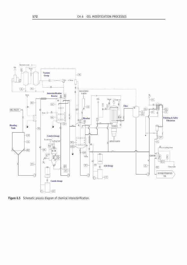
172 CH 6 OIL MODIFICATION PROCESSES
Barometric waterAtm.
Steam
Steam
PI
R
R
R
R
RR
R
R
R
LA
S
LAS
LC
PIA
PI PI
PI
PI
TI
TI
TIC
TIC Clean water
INTERESTERIFIEDOIL
to cooling tower
12681B
PIA
PI
PS
PI
Steam
Steam
OIL INLET
BlendingTank
InteresterificationReactor
Catalyst dosage
Bleacher
Filter
Polishing & SafetyFiltratrion
Acid dosage
Caustic dosage
VacuumGroup
TI TI
TICLS
LS
TIC
BLEACHINGEARTH
To safe areaCATALYST
FIC
PIC
PI
LS
Atm. Steam
SPENT EARTH
Compr. air
LAS
N2
N2
WIC
TI
TI
PI
PI
PS
LS
PI
PI FIC
LS
SIC
LICA
LAS
Steam
R
TIC
R
R
PI
Figure 6.5 Schematic process diagram of chemical interesterification.

6.3 INTERESTERIFICATION 173
A standard randomisation reaction takes about 30–40 minutes, after whichthe interesterified oil has to be post-treated in order to inactivate the catalystand eliminate the remaining soaps formed during the reaction. The inter-esterified oil is pumped to the acid reactor/bleacher. The citric acid dosingpump adds a citric acid solution to the flow of oil pumped in the recirculationby the bleacher oil pump. It is this citric acid that inactivates the catalyst andconverts soaps back to FFA. When the acid reaction is over, the residual waterthat has been introduced in the oil together with the citric acid is evaporatedunder the low pressure applied in the acid reactor/bleacher.
To counteract the darkening of the oil as a result of the reaction, somebleaching earth is dosed from a bleaching earth hopper. From the acidreactor/bleacher, the oil is sent to the interesterification post-treatment mainfilter, typically a leaf filter type.
Filtered oil is collected in the bleached oil tank and then pumped over asafety filter (typically back pulse) to the secondary safety bag filter and oftento a final oil cooler, as it is good practice to cool the oil before storage.
When the differential pressure in the hermetic leaf filter increases abovethe threshold value, the filter needs to be emptied and dried. The drying ofthe cake is done by steam blowing, after which the recovered oil and heelvolume of the main filter are sent back to the bleacher.
The dried cake is finally discharged by vibrating filter elements through aspent earth-collecting hopper to the disposal container.
6.3.4.1 Processed product qualityIn chemical interesterification, the fatty acids will typically be redistributedover the glycerol backbone in a randomised way, and the outcome of theprocess can therefore be relatively easily predicted. This also allows formonitoring of the extent of the interesterification reaction as the mixtureprogresses towards a randomised state, which is especially useful in followingup slow reactions and possibly incomplete reactions. At any moment t, thedegree of interesterification (DI) can be expressed as:
DI(%) = 100∗⎡⎣
(TAG_ATAG_B
)feedstock −
(TAG_ATAG_B
)product(
TAG_ATAG_B
)feedstock −
(TAG_ATAG_B
)random
⎤⎦ (6.2)
where TAG_A represents the triacylglycerol or group of triacylglycerols thatmost proportionally decreases after interesterification and TAG_B is thetriacylglycerol or group of triacylglycerols that most proportionally increasesafter interesterification. The triacylglycerols (TAGs) are expressed as arelative percentage of the total TAGs after normalisation. This formula isflawed, however, when using very small and/or very large values, whichcan lead to large proportional differences. This will make the calculated DI
174 CH 6 OIL MODIFICATION PROCESSES
insensitive to actual physical changes and thus lose relevance. A more robustcalculation would rely on the use of sum of squared residuals (SSR) of allTAG (in which the SSR of the randomised mixture is considered zero):
DI(%) = 100∗
⎡⎢⎢⎢⎢⎣1 −
z∑i=a
(TAGproduct,i − TAG random,i
)2
z∑i=a
(TAGfeedstock,i − TAG random,i)2
⎤⎥⎥⎥⎥⎦ (6.3)
where a and z are the first and the last TAG considered in the TAGdistribution. It’s important to recognise that most conventional TAG analysesdo not differentiate between positional isomers (PPO versus POP), and thatthis calculation does not therefore give information on how this racemisationproceeds throughout the reaction, nor on its end state.
The possible effect of positional isomers is in fact more easily (thoughindirectly) detected by taking the physical properties of the mixture as criteria.It is a more pragmatic approach, as generally the physical properties – likethe solid fat content (SFC) at a certain temperature – are prime qualityparameters by which to trade the product. A common formula based on SFCof the product is therefore:
SFCt − SFC∞SFC0 − SFC∞
= e−k.t (6.4)
The advantage of this expression is that it contains three parameters thathave both a physical and a chemical meaning: the k value is related to thereaction rate of the catalyst and to the SFC0 initial of the feedstock and itschange until equilibrium, which is �SFC. When using SFC as a parameter,it has to be taken into account that it is nonadditive, and that crystallisationeffects that have little to do with the chemical changes as such can occur.
6.3.5 Future for interesterification technologyIn the context of further development of interesterification, possibly the mostappealing possibility for process technologists is ‘directed’ interesterification.The basic idea is to establish a continuously shifting equilibrium within thereaction mixture by letting the formed trisaturated species precipitate andthus become removed from the (liquid) reaction mixture. This would allowa much more controlled and efficient separation of saturated and nonsat-urated triglycerides, instead of a series of interesterification, fractionation,interesterification, fractionation and so on. It is perhaps a little amusing thatthis process is mentioned in a paragraph about the future of the technology,because it is not really new at all; in fact, the principle of directed inter-esterification was described by one of the best known innovators of fats and

6.4 DRY FRACTIONATION 175
oils interesterification, Eckey, in 1948. Such processes, which require (lessefficient) low temperatures to invoke the fractional crystallisation of the insitu produced saturated triglycerides, found some entry into the industry,but the elegant pathway in theory too often turned out to be a troublesomeapplication in practice. In chemical interesterification, it has for now largelybeen abandoned as industrial practice.
Nowadays the benefits of enzymatic interesterification (see also chapter 7)over the chemical pathway (less partial glycerides formation, increased toco-pherol retention, colour preservation, less post-refining costs) have put thelatter in decline for new investments. Indeed, more and more fat processingindustries are shifting to enzymatic processing technology. In this light, itshould not be forgotten that in the commodity oils and fats industry, theeconomy of a process is still more important than its novelty. As such, theattraction of an enzymatic randomisation process consists largely in the factthat it generates fewer oil losses than the chemical technology, rather than anenhanced (or faster) randomisation. It also means that enzymatic technologywill be adopted by fats and oils manufacturers for as long as the enzymecost does not exceed the cost of oil losses that can be expected in chemicalinteresterification. Though the quality and the stability of the enzyme lipaseshave evolved considerably, the general perception in the industry is thatthis technology is less robust than its chemical counterpart. In some cases,a properly fine-tuned chemical process is therefore still preferred over theenzymatic pathway.
6.4 Dry fractionationIn edible oils processing, the term ‘fractionation’ usually refers to any processinvolving a fractional crystallisation of the oil as the means of separatingspecies based on melting point. The general aim of the process is to extendthe applicability of the feedstock, be it through the reduction of an undesiredcomponent or the intentional concentration of another.
The actual crux of such fractionation process is a crystallisation process;hence ‘fractional crystallisation’ is nowadays often used as a more evoca-tive synonym. Also, in fractionation discipline, the edible oil industry isturning away from technically superior solvent or detergent fractionationdue to safety and investment issues, as well consumer perception. However,the need for high-quality oil fractions has not disappeared, so the combi-nation of these factors has pushed the boundaries of the most sustainablepathway in this field: the fractional crystallisation of the pure oil, or dryfractionation. Other oil fractionation techniques have been developed andapplied in recent decades, among which molecular distillation and supercrit-ical carbon dioxide extraction are certainly noteworthy. Although the said

176 CH 6 OIL MODIFICATION PROCESSES
alternative technologies can offer specific advantages with regards to specificseparation efficiency (enrichment of high-value minor components, reductionof unwanted minor components), the economics of such processes excludetheir broad implementation for bulk edible oil processing. Therefore, in theremainder of this chapter, the focus will be on the fractional crystallisation ofedible oil, which is the norm in the fats and oils industry.
It should be remarked that compared to hydrogenation and chemicalinteresterification, dry fractionation technology has undergone substantialdevelopments in order to achieve the current state of the art. Whereas dryfractionation was often regarded as an unpredictable, tedious and labour-intensive process, and the relatively cost-effective fractionation techniqueas being without additives, polluting effluents or the necessity for post-refinement, the sustainability and safety of the dry fractionation process aresecond to none. Because of these features, it is perceived as the modifica-tion technology of the 21st century (Timms, 2005), which warrants a moreelaborate discussion.
6.4.1 Historical perspectiveIn most literature on fat fractionation, Hippolyte Mege-Mouries is creditedwith the invention of a patented method to produce certain fats of animalorigin. In fact, he concocted the production of a sort of margarine fatthrough the separation of a liquid fraction from ordinary tallow after gentlecooling. With only temperature difference as a driving force, the fractionalcrystallisation of a fat is a natural, spontaneous phenomenon. It was thus alsoobserved that in palm (kernel) oil harvested in tropical regions, small crystalswould appear upon cooling and form a crystal suspension in the woodenbarrels during shipping to chillier Western Europe. These slightly densersolids eventually settled, and such fractions could effectively replace hardenedfats in margarines. We can therefore consider these wooden shipping drumsthe very first oil crystallisers, with the ocean waves providing the gentleagitation to keep the developing crystals in suspension. Moreover, the naturalfractional crystallisation of fats upon mild cooling is echoed in the term‘winterisation’, referring to the habit of leaving large oil tanks quiescent inwintertime to induce some mild crystallisation and obtain a liquid fractionwith improved cold stability, in a rather economic fashion.
Despite the apparent spontaneity of the process itself, it took until the 1960sfor the fractionation industry (and technology) to boom, when the productionof palm oil in South East Asia increased substantially and export taxes onprocessed palm oil were reduced. At that time, however, the boundariesof the technology were mainly determined by the phase separation. Inrecent decades, the continuous development of the separation technique

6.4 DRY FRACTIONATION 177
in particular – from vacuum belt filtration to centrifuges and membranepress filters – has put fractionation on the map as a versatile and economicmodification technique. Although some specific techniques relying on the useof detergents are still applied for very particular productions, only two mainfractionation technologies are used in the 21st century’s edible oil industry:
• Dry fractionation, also known as crystallisation from the melt: this is frac-tional crystallisation in its most simple form, and the economy of thetechnology allows it to be used for the production of commodity fats.
• Solvent fractionation: already patented in the 1950s, this involves the useof hexane or acetone to allow the high-melting components to crystallisein a very low-viscous organic solvent. This can be helpful with respect tothe selectivity of the reaction, but mainly offers advantages in the field ofphase separation: much purer solid fractions can be obtained, even with avacuum filtration. Being a more expensive process, it is far less commonthan dry fractionation and only comes into the picture when a very highadded value of (at least one of) the resulting fractions makes up for thehigh cost.
6.4.2 PrincipleIt is not in the scope of this chapter to cover all aspects of crystallisation of oil,such as nucleation, crystal growth and so on; however, the principal conceptsneed at least to be concisely explained since they do have serious implicationsfor the level of the technology.
Natural oil, even after refining, is a very complex mixture of differenttriglycerides (and numerous other minor components), which has importantrepercussions for the melting behaviour of a fat: most oils do not exhibita sharp melting point, but rather display a steady softening (or increasingliquid content) with increasing temperature, until they are completely liquid.The fact that oil is a mixture allows it to be considered as a heterogeneoussystem of at least two separable fractions – a solute and a solvent – at a giventemperature.
There are three variables that can be used to consider whether a certaintriglyceride will remain in the melt (behave like solvent) or crystallise (behavelike solute): the absolute melting temperature of the triglyceride, the con-centration of the triglyceride and the bulk temperature. Their relationship isexpressed by the van ’t Hoff equation:
Inx = �Hm
R
[1
Tm− 1
T
](6.5)
where x is the solubility of the solute (mol/mol), �Hm is the heat of fusion ofthe pure solute (kJ/mol), Tm is the melting temperature of the solute (K), T is

178 CH 6 OIL MODIFICATION PROCESSES
76 5
4
32 1
1
0.9
0.8
0.7
0.6
0.5
Con
cent
ratio
n of
sol
ute
in m
elt (
−)
0.4
initial concentration of solute
desired concentration of solute
0.3
0.2
0.1
0300 305 310 315 320
Temperature (K)
325 330 335 340 345
Figure 6.6 Solubility diagram with schematic representation of fractional crystallisation.
the experimental temperature (K) and R is the gas constant (kJ/mol.K). Forany triglyceride, a solubility line can be constructed as function of temperature(Figure 6.6).
In this schematic representation, the fractional crystallisation process isthus essentially as follows:
(1) Approach the solubility line (cooling the melt).(2) Supersaturate the solution to initiate the crystallisation (cooling into the
metastable zone).(3) Equilibrate the solid/solution suspension (the solute triglyceride pre-
cipitates till the equilibrium situation on the solubility line is reachedagain).
(4) Supersaturate the suspension.(5) Equilibrate the solid/solution suspension.(6) Supersaturate the suspension.(7) Equilibrate the solid/solution until the desired final residual concentration
of the solute in the melt is reached.
After this process is completed, the crystal suspension is ready for filtration.The solubility line also enables the fact that for every additional decreasein the solubility of a solute, proportionately lower cooling temperatures areneeded to be appreciated.

6.4 DRY FRACTIONATION 179
The complex nature of fractional crystallisation in natural oils becomesapparent when we consider that for each type of triglyceride present, suchsolubility lines can be constructed. More importantly, ideal solubility curveslike the one in Figure 6.6 actually ignore the occurrence of interactionsbetween different triglyceride molecules. This indicates that the solutionbehaviour of a triglyceride is itself influenced by the surrounding triglyceridesin the melt. Even in rather simple model fat systems, small but significantdeviations will occur (Zhou & Hartel, 2006). In the context of fractionation,‘intersolubility’ is the most important kind of interaction: it generally refers tothe property of forming a solid ‘solution’ in which the constituting triglyceridescannot be separately determined, nor divided; it behaves as one phase. Thephysical chemistry behind this is in fact comparable to that applying to metalalloys. The more structural resemblance two triglycerides have, the highertheir miscibility in a solid state.
Consequently, such intersolubility of the TAG often presents the largestfundamental problem in several fractionation processes, as the actual goalof fractionation is to separate different TAGs selectively. Intersolubility,however, can occur to a considerable degree in practice, and can have verynegative effects on both the viscosity and the filtration properties of the crystalsuspension formed (Calliauw et al., 2010). Although in theory intersolubilitybetween two species decreases with decreasing temperature, the problem ina multicomponent system such as oil is that with decreasing temperature,the number of different triglycerides that can crystallise will increase, makingundesired interactions more likely to happen. Therefore, intersolubility willdetermine to an appreciable extent how many supersaturation/equilibrationsteps are needed to achieve the desired residual concentration in the melt.The less susceptible the oil system is to intersolubility effects, the deeperthe supersaturation can be, and consequently, the fewer ‘steps’ (or time)needed to reach the final point on the solubility line. Upon stringent cooling,excessive nucleation, crystal growth and intersolubility effects result in theformation of interconnected, homogeneous lumps of fat that are practicallyunfilterable. This explains why fractional crystallisation in most cases cannotbe executed by simply crash-cooling the oil (unlike in margarine production,where fat crystal networks are desired).
Compared to intersolubility, other typical fat crystallisation phenomenasuch as polymorphism are only of secondary importance; typical fractionationconditions are generally sufficiently restricted in time and temperature rangeto only allow one type of molecular arrangement to form.
The solubility diagram (or binary phase diagram) also lacks a very impor-tant aspect of the crystallisation reaction: the kinetics. For these relativelylarge organic molecules, crystallisation in the melt is a rather slow reaction,hampered by limited heat and mass transfer between bulk and interface.Intuitively, it can be understood that the deeper the saturation (i.e. the

180 CH 6 OIL MODIFICATION PROCESSES
driving force), the more rapidly the crystallisation reaction will occur. Thefirst supersaturation is typically quite severe, in order that it can induce afast nucleation of the very first crystals. Achieving supersaturated conditionsas such is technically not difficult; it just comes down to the removal of thesensible heat of the oil (at a rate of 0.5 kcal/kg.K) and it occurs quickly in mostcrystallisers. For this reason, the supersaturation trajectories can commonlybe drawn parallel to the x-axis: the temperature is decreased well below thesolubility line, even before the triglyceride starts to solidify, and thus theconcentration remains constant. In the example, the equilibrium stage occursisothermally, but in practice this is quite difficult to achieve, as it implies zerotemperature gradients in the crystalliser during crystallisation. The exother-mic character of crystallisation (latent heat: about 50 kcal/kg) and the slowheat transfer in oil evidently make this supposed homogeneity a very toughsituation to realise in practice.
Essentially, all of the preceding can be condensed to the statement thata good fractional crystallisation can be achieved when the melt is kept justsufficiently in metastable condition to create a driving force for crystallisationof triglycerides of interest. But at the same time, the conditions need to besufficiently close to the solubility line in order to prevent formation of solidsolutions between desired and undesired triglycerides and/or uncontrolledcrystal growth from hampering filtration. If the crystal growth is regular andsteady, the crystal aggregates result in sharply discrete and dense spheruliticstructures, sometimes measuring up to several millimetres in diameter (gen-erally larger with lower supersaturation conditions), which are fairly uniformin size and shape (Figure 6.7).
To conclude this section, the influence of minor components on oil crys-tallisation should also be addressed. Overall, ‘impurities’ such as diglyceridesor FFA have a negative effect on the crystallisation rates of the triglyceridesof interest at typical fractionation temperatures and on the filterability of thesolids formed (Siew & Ng, 1999; Calliauw, 2008).
6.4.3 Process parametersThe basic principles sketched in this section help to explain the key aspectsof a crystalliser, the technological heart of the fractionation installation. Itshould be able to gently cool down a mass of oil (up to 100 tonnes/batch) andkeep the resulting crystal suspension as homogeneous as possible.
6.4.3.1 Cooling speed
Fat crystallisation is an exothermic reaction, so the efficiency with which thisenergy can be evacuated is an important design feature. For most industrialcrystallisers, this ranges between 120 and 200 W/m2.K.

6.4 DRY FRACTIONATION 181
Figure 6.7 Spherulitic crystals formed in palm oil.
In view of this, the most important feature in fractionation technologyis ensuring proper and homogeneous heat transfer in the crystalliser. Atevery stage of the cooling and crystallisation process, the temperature ofthe oil should be kept in a state that permits crystallisation to the desireddegree. Generally, a crystallisation process can be broken down into severaltemperature stages. In these stages, the manner of oil cooling can be based on:
• selecting a fixed oil temperature (meanwhile allowing the cooling watertemperature to vary between set limits); or
• selecting a �T, a fixed temperature difference between oil and coolingwater; or
• selecting a fixed temperature for the cooling water.
Typically, the first two process control modes have been labelled as thetypical cooling strategy in Tirtiaux-designed crystallisers, whereas the watertemperature control has characteristically been applied in Desmet Ballestra-designed processes. This distinction has been stated in many fractionationreviews over the last 20 years. However, currently most fractionation plantsare built to offer total freedom in terms of process control: in every step ofthe process, the mode of process control can be selected (Figure 6.8).
In this context, it is a rather widespread misconception that, for example,oil temperature control is slower than water temperature control: the speed of

182 CH 6 OIL MODIFICATION PROCESSES
(a)
Water Temperature Control
Time
Tem
pera
ture
(b)
Time
Tem
pera
ture
(c)
Time
Tem
pera
ture
Water TOil T
Delta Temperature ControlWater TOil T
Oil Temperature ControlWater TOil T
Figure 6.8 Different oil cooling modes used in dry fractionation: (a) water temperaturecontrol; (b) delta temperature control; and (c) oil temperature control.

6.4 DRY FRACTIONATION 183
the crystallisation cycle is largely determined by the size of the average coolingdriving force imposed. So regardless of the mode of process control, largertemperature gradients between water and oil will lead to shorter processes(so higher throughput), until the point at which filterability is affected (soyield and stearin purity decrease). In practice, the cycle times can vary upto a factor 3, depending on the average imposed �T, and the challenge is tooptimally balance yield, fraction quality and capacity.
6.4.3.2 Agitation
Since oil is a poor heat conductor, heat transfer should occur mainly throughbulk mixing and friction with the cooling surface. This force is supplied by theagitator, which is often positioned quite close to the cooling surface, in orderto make sure the oil just cooled can be readily brought back to the bulk.
Agitation is necessary not only for heat exchange but also for mass transfer.In fact, the cooling of oil does not only happen at the cooling surfaceinterface; it’s also the result of colder oil getting mixed with the warmer bulkoil. Specifically for mass transfer, the agitation has to prevent the settlingof the crystals being formed and distribute them homogeneously over thebulk, so that concentration gradients don’t get too high either. Also, as manyauthors agree that secondary nucleation (i.e. crystal growth on earlier formedcrystal surfaces, instead of de novo formation in the melt) is highly relevantfor industrial crystallisation applications (Mullin, 2001), it is the underlyingmechanism of crystal seeding in crystallisation processes. It can explain tosome extent why such nucleation is promoted by higher agitation: crystalsget shattered when colliding with each other, with the impeller or withthe crystalliser wall. Although secondary nucleation is rather inevitable inindustrial processes, Timms (2005) stated that this phenomenon is generallyundesirable in fractionation, and agitation in an industrial crystalliser istherefore kept to a minimum: just enough to keep the heat transfer and bulkmixing intact. Industrial tip speeds easily range up to 3 m/s at the start ofcrystallisation, but can drop below 1 m/s in the final (more viscous) stages.
6.4.4 Process design6.4.4.1 Crystalliser design
Compared to crystalliser designs for oleochemical or pharmaceutical prod-ucts, for example, edible oil crystallisers are quite basic. In view of the need toreduce concentration and temperature gradients as much as possible, the con-servation of the mass and heat transfer properties over the length of the batchprocess has been the main challenge for edible oil crystallisers. The completerange of viscosity of the oil (from about 50 cP of liquid oil to sometimes reallythick slurries with non-Newtonian rheological properties). Oil being a very

184 CH 6 OIL MODIFICATION PROCESSES
poor heat conductor, the rate-determining step in heat exchange between thebulk oil and cooling water is the mass transfer from bulk to interface oil.Excessive cooling without sufficient renewal of the interface oil will only resultin the precipitation of a vast (unfilterable) mass of crystals on to the coolingsurface and consequent complete loss of process temperature control. Only incases where a very fast crystallisation reaction is used (and thus a great drivingforce is created) to keep the economy of the process in check, such as in solventfractionation, can scraped surface heat exchangers be used to counteract thiscrystal loading, even if this comes with the drawback of crystal fragmentation.
A simple batch crystalliser is the ‘tubular crystalliser’: a double-jacketedcylindrical vessel fitted with an axial agitator at its centre. Normally a coolingsurface of at least 5 m2 per 1 m3 oil is needed to ensure proper heat transfer.In practice, this limits the dimensions of tubular crystallisers to the extentthat it is only used for low-volume speciality fats and less frequently forcommodity edible oil products, such as palm oleins. For the fractionationof palm oil, large crystallisers are needed, and various means of providingadditional cooling surface have been developed. A substantial increase incooling surface per unit volume of oil can be obtained by dividing concentricannular crystallisation compartments that are separated by concentric,annular, double-walled cooling elements (Kellens et al., 2007). The mostconventional type of crystalliser used in the last few decades is the tankcrystalliser, in which the cooling surface is built inside a tank in the form of(horizontal) cooling coils, (vertical) pipes and/or cooling plates. Generally,such crystallisers are equipped with propeller-type blades, inducing aconvection-like flow pattern through the tank.
Notwithstanding the basic character of edible oil crystallisers, severalenhancements can be made within or just outside them, such as seeding tanks(to make a kind of pre-mix of crystals and reduce crystal initiation time) andhot oil spray pipes to clean the cooling surface from the residual precipitatedcrystalline matter after batch draining. Due to concerns over increasingperoxides, this practice is nowadays generally abandoned. Another practiceis the implementation of an ultrasonic precrystalliser, facilitating crystalnucleation in the bulk prior to its entry into the crystalliser.
6.4.4.2 Filter designAlthough the triglyceride separation is in theory already established duringcrystallisation, it is clear that the separation stage itself effectively determinesthe product yields as well as the stearin quality. As more residual olein isexpelled from the solids cake, the final stearin will be more concentratedin crystals, will turn out ‘purer’ and will display higher and steeper melting.The olein quality is determined entirely by the amount and selectivity ofcrystallisation in the preceding stage. In some applications, the crystalsformed are often not sufficiently stress-resistant and get squeezed through

6.4 DRY FRACTIONATION 185
Table 6.7 Separation efficiencies of different filtration technologies in dry fractionation ofpalm oil.
Vacuumfiltration
Centrifugalnozzles
Membrane press(16 barg)
IV palm oil 52 52 52IV palm olein 56–57 56–57 56–57IV palm stearin 40–42 36 30–32Solids in cake (%) 46 – 65Olein Yield (%) 72 76 82
the filter medium. Obviously, such contamination of crystals in the olein phasenegatively affects the efficiency of the fractionation process and results in aliquid phase with inferior cold stability properties. Overall, the ‘permitted’degree of olein dilution in the stearin cake determines the choice for theapplied separation technology (Table 6.7).
Membrane press filtration, also used in, for example, sludge dewateringsystems, is by far the most widely used separation technology in dry fraction-ation today. The filters consist of a large steel frame that can easily hold upto 150 filter plates together, each plate counting for up to 7 m2 of filtrationsurface and over 100 l filter chamber volume.
Usually, the filter chambers are first filled with the crystal suspension, and alarge portion of the liquid olein thus passes through the filter cloths. Watertightmembranes (one membrane per chamber) attached to the internals of theplates are then gradually inflated (with water, liquid oil or air) to the desiredpressures, reducing the chamber volume and pushing out residual liquid,which is immediately evacuated via internal channels in the plate towardscollecting tanks. The volume reduction of the chamber thus compacts anddries the cake. Typical final squeeze pressures are 6 or 15 barg; 30 and even50 barg membrane press filters are available on the market if higher purity isneeded in speciality fat cakes. It is also noteworthy that the mass fraction ofsolids in the filter cake decays exponentially as a function of the distance tothe filter cloth, and consequently thinner filter chambers (from 15 to 50 mmchamber widths) and longer squeezing times can be a helpful (though costly)means of significantly reducing the entrainment.
6.4.4.3 Plant designA general layout of a present-day dry fractionation process is presented inFigure 6.9. Often multiple crystallisers are used in (overlapping) series. Thisis not only a matter of capacity; it is also done in order to maximise the useof the filter: through good planning of the crystallisation times, the expensive(batch) filter should be in constant operation. It is important to note that

186 CH 6 OIL MODIFICATION PROCESSES
OIL TOFRACTIONATION
MF1002A1 MF1002A2
F1002A1
TO FILTRATION
Clean coolingwater
Clean coolingwater return
Steam
Steam
T1
SIC
SIC
SIC
LS LS
TI TILI LI TI LI
LS
TIC
LS
TIC
LIC
TI
TCRLS
TIC
LAS
LSTICA
Steam
Clean coolingwater
(a)
TIC
LAS
Feed Section
Chilled & HotWater section

6.4 DRY FRACTIONATION 187
LS
TILI
LS
TI
LS
SIC
PI
SteamSteam
Steam
TIC
LI
SIC
(b)
PIC
Blow airMembranePress Filter
Stearin Melting &Heating
Wash Pump Squeeze Pump
Olein Tanks
PS
PICA
PIA
TI
TIC
TIC
Steam
Steam
to Atm.
Stearin
OleinLI
Figure 6.9 Schematic process diagram of dry fractionation, consisting of (a) crystalliser section and (b) filter section.

188 CH 6 OIL MODIFICATION PROCESSES
fractionation is a quite modular technology and very often results in a tailor-made plant; several water tanks (two to four), all at different temperatures,can be installed in order to maximise heat recuperation while keeping allcooling medium in a closed loop, but this can just as well be done with asingle tank feeding chilled water to the crystallisers, while steam is added tosupply heat and normal cooling water is fed directly from a clean coolingtower. Similar tailor-made selections can be used for the filter section: thesqueezing medium in the membranes can be water, but could equally be thefiltrate itself! In some cases, a significant reduction in the dead time of afilter can also be established by means of a crystallised oil buffer tank; eachcrystalliser can be quickly drained and made ready to receive the next batchof oil. Meanwhile, the cooled buffer tank will send set volumes of crystalslurry to the filter, whenever it is ready.
Continuous filtration systems have also been a very elegant strategy indry fractionation, although currently the demand for purer solid fractionsas obtained by filter chamber compaction has pushed continuous belt filterssomewhat out of the dry fractionation market. They are however still thenorm in solvent fractionation.
It should be kept in mind that fractional crystallisation of a triglycerideoil is a relatively slow process and is therefore the time-determining stage;some simple fractionations can be established in about 5 hours of crystalliserresidence time, whereas more complex oils can require up to 3 days of coolingand crystal maturation before being sent to the filter. The whole filtrationplus squeezing operation can take from 30 to 90 minutes.
6.4.5 Future for fractionation technology6.4.5.1 Optimised crystalliser designs
The innovations in the field of oil crystallisers have been orientated towardsimproved heat-exchange cooling geometries, in all possible variations: doublejackets, cooling plates, cooling coils and their relative positions in the crys-talliser body. Additionally, agitator types (propeller paddles, surface scrapers,plate paddles etc.) have also been the subject of study. Industrial crystalliserstherefore exist in all shapes and forms. Interesting innovations in this fieldin recent years use agitation with an integrated cooling system, such as theSTAR-crystalliser (Weber et al., 1998), consisting of a collection of rotatingcooling bundles, and the MoBulizerTM (Calliauw, 2008). The latter designfeatures a very uniform linear movement of the homogeneously distributedcooling surface (Figure 6.10).
Industrial results indeed point to considerably higher heat-exchange effi-ciencies compared to slow-stirred crystallisers, and to improved results forshear-sensitive crystals, such as those formed in tallow and lard fat.

6.4 DRY FRACTIONATION 189
Figure 6.10 Detail of MoBulizerTM cooling tubes in vegetable oil. The full colour version canbe found on the plates.
Probably the most significant crystalliser design of the last decade is theStatolizer crystalliser (Calliauw et al., 2005), designed specifically to form anddeal with very viscous slurries that are practically unstirrable in a conventionalcrystalliser. It has been introduced in the industry as an automated system toreplace panning-and-pressing cold rooms, and over the years has become astandard for palm kernel oil fractionation in the production of cocoa buttersubstitutes. Further product developments based on Statolizer technologyare occurring in the production of cocoa butter equivalents (CBEs) and evenplain cocoa butter fractionation (Calliauw et al., 2011).
6.4.5.2 High-pressure filtrationsSpurred on by the demand for speciality (confectionery) fats, the liquid–solidseparation technologies are under continuous pressure to push the boundariesof the separation efficiency. Now 30 barg cake squeezing pressure is wellestablished, and there is increasing interest in 40 or 50 barg. It should berealised that at these very high pressures, there is a diminishing marginalreturn of olein yield per barg of extra pressure applied. However, it coulddeliver a crucial purity of stearin composition for some high-end applications.There has also been a (renewed) interest in centrifugal separator systems,especially with respect to fish oil fractionation and cross-contamination in
190 CH 6 OIL MODIFICATION PROCESSES
sensitive processes. However, separation efficiencies cannot really competewith the high-pressure membrane press filters for most applications.
Other features that are widely integrated in contemporary dry fraction-ation filter assemblies include antistatic filter plates and cloths, replaceablepolypropylene membrane units (instead of the whole plate), cake droppingdetectors, facilitated cake discharge shakers or pendulums, ‘self-cleaning’inlet ports, membrane leak detectors, light safety barriers and many more,all of which contribute to a safe, fast and consistent functioning of the filterpress, but do not touch the core of the technology.
Solvent fractionation technology usually operates with gas-tight vacuumbelt filters, an important advantage of which over membrane press filters is thepossibility of (multiple) countercurrent washing of the stearin cake, resultingin a physical displacement of remaining olein miscella by pure solvent andtherefore the production of purer stearin fractions.
6.4.5.3 Continuous fractional crystallisationMainly in the final decade of the 20th century, the possibilities of continu-ous fat fractionation on anhydrous milk fat were studied, with results thatresembled those obtained by traditional batch dry fractionation (Illingworth,2002). Quite atypically for dry fractionation purposes, a scraped-surface heatexchanger (SSHE) can be used as a plug-flow reactor (PFR). In all suchdesigns, however, a batch membrane press filtration is still recommended, inorder to reduce the entrainment of olein within the stearin cake. Therefore itis more correct to define them as continuous crystallisation techniques ratherthan complete continuous fractionation systems. A vacuum belt filter orhyperbaric filters can be considered to meet this objective of total continuityof the process, although they yield less thorough phase separation comparedto membrane press filters.
Continuous fractionation of palm oil is regarded as probably the mostpromising pathway for future dry fractionation. An important challenge incontinuous fractionation is to avoid complete mixing while maintaining ade-quate heat and mass transfer in a low viscous suspension. In order to achievethis, contemporary batch crystallisers with the desired homogeneous mixingshould be redesigned to function as PFRs, allowing minimal back-mixing andensuring uniform residence time upon continuous product throughput.
A good continuous fractional crystallisation technique has considerableadvantages for plant operation: it can increase throughput, it will reduceinterbatch variability, it can improve the homogeneity of the particle sizedistribution in the slurry leaving the crystalliser and it offers a substantialenergy saving. This economy exists because the longer a crystalliser can run ata the same temperature, the more equivalent ‘batches’ it can produce withoutreheating or recooling of the crystalliser’s steel and water. Additionally,substantial energy economisation can be achieved by crossing the hot ingoing

6.4 DRY FRACTIONATION 191
Table 6.8 Comparison of batch and continuous dry fractionation of palm oil (Calliauw et al.,2011).
Batch Continuous
Average residence time (hours) 5 4.5Average runtime before draining (hours) 5 150SFC of the slurry (%) 8.7 8.4
Stearin Olein Stearin Olein
Mettler cloud point (◦C) [−3 ◦C] 9.8 9.4IV (Wijs) 32.5 56.2 30.1 56.3Yield (%) 18 82 16.5 83.5
feed with the cold olein leaving the plant for storage. Such a setup can amountto a 20–30% steam (or hot water) and proportional cooling power reductionin the first step of palm oil fractionation. The constant presence of crystals inthe crystalliser helps to reduce the degree of supercooling needed to initiatethe crystallisation (as in a batch process).
Table 6.8 demonstrates the industrial results of a recently developedcontinuous crystallisation process with crystallisers operated in a plug-flowmode. It was to be capable of producing various palm (super) olein qualities,at yields superior to those of the batch process, for a duration up to 50equivalent batch cycles.
6.4.5.4 Alternative multistage processes for specialty fats production
The apparent simplicity, low operation costs and sustainable character havemade dry fractionation a ‘technology to stay’, but, as for all modificationtechnologies, developments in the field are propelled by two driving forces:cost reduction and higher added values of the products. Whereas cost reduc-tion is a relatively universal and direct process-related issue (in the form oflower consumption costs, lower investments, increased yields, higher degreeof automation, reduced losses etc.), adding more value to the fat fractionsis a more specific market-driven matter, imposed in fact by the consumer.This ‘added value’ is the premium price a customer is willing to pay for anedible oil product that exhibits specific functional properties such as improvedcold stability, low saturates contents, increased docosahexanoic acid (DHA)levels and so on for liquid products; and steeper melting curves and fatstructuring properties at minimal saturates content for solid products. Theeconomic driver can also exist in the form of the successful imitation ofspecific properties of expensive ‘natural’ fats and oils by relatively cheaperoils such as palm oil fractions, which explains the huge interest in CBEs,replacers and substitutes.

192 CH 6 OIL MODIFICATION PROCESSES
Temperature (°C)
0 10 20 30 40 50 60 70
Sol
id F
at C
onte
nt (
%)
0
20
40
60
80
100
Palm Oil
Palm Olein
Palm Stearin
Superolein
Soft PMF
Mid Olein
Hard PMF
Mid Stearin
Hard Stearin
Figure 6.11 Overview of palm oil fraction melting curves in multistage fractionation. The fullcolour version can be found on the plates.
So the main economics of dry fractionation is determined by how muchadded value both fractions produced can generate payback of the feedstockcost and operation costs. This explains the ongoing diversification of mul-tistage fractionation processes: as the consumer raises the bar in terms ofquality, fractionation processes need more concentration steps to achieve theproduct properties that can meet these demands.
A good example is how palm superolein (the olein fraction of the olein ofpalm oil) has to meet ever-increasing cold stability demands: at the end ofthe 1990s, commodity superolein exhibited IV values around 63, whereas 10years later a minimum IV of 65 or 66 is considered a standard superolein.The desired quality (specifically the ‘cold stability’) of these commodity oleinproducts is thus slowly yet steadily increasing (Figure 6.11).
At the other end of the spectrum of multistage palm oil fractionation,superstearin production is receiving increased attention, as superstearin, withIVs ranging from 9 to 13 (depending on the squeezing pressure used), is todayconsidered an optimal (trans-free) concentration of saturated triglycerides.
Finally, the mid fractions, particularly the hard palm mid fraction (PMF),can be regarded as those fractions in which the symmetrical monounsaturated

6.4 DRY FRACTIONATION 193
Tabl
e6.
9Ba
sic
cost
esti
mat
ion
ofed
ible
oilm
odifi
cati
onpr
oces
ses.
Allc
osts
inU
Sdo
llars
.
Hig
h-pr
essu
rehy
drog
enat
ion
(+po
st-t
reat
men
t)
Chem
ical
IE(+
post
-tre
atm
ent)
Enzy
mat
icIE
Palm
oil
frac
tion
atio
nPa
lmol
ein
frac
tion
atio
n
Plan
tca
paci
ty(t
pd)
180
140
100
200
100
Annu
alca
paci
ty(a
t34
0w
orki
ngda
ys/y
ear)
6120
047
600
3400
068
000
3400
0
Capi
tali
nves
tmen
tsEq
uipm
ent
and
engi
neer
ing
$150
000
0$1
100
000
$100
000
0$1
600
000
$200
000
0
Stru
ctur
alw
orks
$600
000
$500
000
$450
000
$800
000
$900
000
Inst
alla
tion
$750
000
$700
000
$600
000
$855
000
$900
000
ROI
$285
000
0$2
300
000
$205
000
0$3
255
000
$380
000
0Ca
pita
lcos
t/to
nne
7.8
8.1
10.0
8.0
18.6
Annu
alm
aint
enan
ceco
sts
$40
000
$40
000
$50
000
$50
000
$60
000
Oper
atio
nco
sts
Man
pow
er2
11
11
Cons
umpt
ion/
tonn
eSt
eam
kg/t
onne
oil
3015
012
4063
Elec
tric
ity
kWh/
tonn
eoi
l10
154
1016
Nica
taly
stkg
/ton
oil
20
00
0H
ydro
gen
m3 /
tonn
e50
00
00
NaOM
eca
taly
stkg
/ton
neoi
l0
10
00
Enzy
me
kg/t
onne
oil
00
0.4
00
Citr
icac
idkg
/ton
neoi
l0.
52
00
0Bl
each
ing
eart
hkg
/ton
neoi
l1.
55
00
0Oi
llos
ses
kg/t
onne
oil
−318
0.6
00
Uti
lity
unit
cost
sOp
erat
ion
cost
/ton
ne$9
000
0M
anpo
wer
$/ye
ar$2
.9$1
.9$2
.6$1
.3$2
.6
(con
tinue
dov
erle
af)

194 CH 6 OIL MODIFICATION PROCESSES
Tabl
e6.
9(c
ontin
ued)
Hig
h-pr
essu
rehy
drog
enat
ion
(+po
st-t
reat
men
t)
Chem
ical
IE(+
post
-tre
atm
ent)
Enzy
mat
icIE
Palm
oil
frac
tion
atio
nPa
lmol
ein
frac
tion
atio
n
$0.0
3St
eam
$/kg
$0.7
5$3
.8$0
.3$1
.0$1
.6$0
.15
Elec
tric
ity
$/kW
h$1
.5$2
.3$0
.6$1
.5$2
.4$4
.0Ni
cata
lyst
$/kg
$8–
––
–$1
.0H
ydro
gen
$/m
3$5
0–
––
–$2
.5Na
OMe
cata
lyst
$/kg
–$2
.5–
––
$55.
0En
zym
e$/
kg–
–$2
2.0
––
$1.7
8Ci
tric
acid
$/kg
$0.9
$3.6
––
–$0
.65
Blea
chin
gea
rth
$/kg
$1.0
$3.3
––
–$0
.85
Oill
osse
s$/
kg$(
3)$1
2.2
$1–
–M
isce
llane
ous
$2$2
$2$2
$2Op
erat
ion
cost
/ton
ne$6
5$3
2.3
$29.
5$6
.1$1
0.4
Tota
lcos
t/to
nne
$73
$40
$40
$14
$29

REFERENCES 195
triglycerides (mainly POP) are concentrated. These generally generate themost added value, but are not obtained in high yields. In general, 100 tonnesof palm oil entering a multistage fractionation will yield only about 8–12tonnes of good-quality hard PMF.
There is no reason to limit multistage processing within the field of fraction-ation. Indeed, a logical step is to actively combine the technological noveltiesof all available modification technologies to add value to the final product.This is already done on the industrial scale, where many oil manufacturerscombine hydrogenation, interesterification and fractionation to customisespecific fat properties. Another way of approaching possible combinations isnot from a product point of view, but rather from a process point of view. Oneof the avenues of investigation is to conduct a partial (enzymatic) interesteri-fication before dry fractionation, in order to improve the reaction kinetics inthe latter technology, rather than improve the oil product quality itself.
6.4.6 SummaryIn the fractionation discipline, the edible oil industry has turned away fromtechnically superior solvent or detergent fractionation due to safety andinvestment issues, as well as consumer perceptions. However, the need forhigh-quality oil fractions has not ceased, so the combination of these factorshas led to a pushing of the boundaries of the most sustainable pathway inthis field: the fractional crystallisation of the pure oil, or dry fractionation(Table 6.9). Crystalliser designs are evolving towards more sophisticatedtanks, with a primary focus on reducing temperature gradients in the bulk.
Contemporary filter designs exhibit greater ease of use, a higher degree ofautomation and increased safety. Further, the overall separation efficiency isdefinitely superior to that of the standard design of 10 years ago. The mostrecent innovations are to be found in the expansion of the possible edibleoil applications spectrum by means of multistage fractionation, as well asin economic improvement of the process through integration of continuouscrystallisation (plug-flow) reactors and heat-recovery systems in the plant.
ReferencesBeers, A., Ariaansz, R. & Okonek, D. (2008) Trans isomer control in hydrogenation of
edible oils. In: A.J. Dijkstra, J. Richard, R.J. Hamilton & W. Hamm (ed.) Trans FattyAcids. doi: 10.1002/9780470697658.ch6.
Boger, T., Zieverink, M.M.P. Kreutzer, M.T., Kapteijn, F., Moulijn, J.A. & Addiego, W.P.(2004) Monolithic catalysts as an alternative to slurry systems: hydrogenation of edibleoil. Ind. Eng. Chem. Res., 43, 2337–2344.
Calliauw, G. (2008) Molecular interactions affecting the phase composition during dryfractionation of palm olein. PhD thesis, Ghent University, Belgium.

196 CH 6 OIL MODIFICATION PROCESSES
Calliauw, G., De Greyt, W., Dijckmans, P., Foubert, I., Dewettinck K. & Kellens, M.(2005). Production of cocoa butter substitutes via two-stage static dry fractionation ofpalm kernel oil. J. Am. Oil Chem. Soc., 81, 783–789.
Calliauw, G., Fredrick, E., Gibon, V., De Greyt, W., Wouters, J., Foubert, I. & Dewet-tinck, K. (2010) On the fractional crystallization of palm olein: solid solutions andeutectic solidification. Food Research International, 43, 972–981.
Calliauw, G., Hendrix, M. & Kellens, M. (2011). Dry fractionation of speciality fats: adecade of statolizer fractionation technology. Paper presented at the MPOB Interna-tional Palm Oil Conference, Kuala Lumpur, Malaysia.
Dijkstra, A.J. (2009) Interesterification revisited. Alton E. Bailey Award Address presentedat the 100th AOCS Annual Meeting & Expo, Orlando, FL, USA.
Dijkstra, A.J. (2010) Selectivities in partial hydrogenation. J. Am. Oil Chem. Soc., 87,115–117, doi: 10.1007/s11746-009-1507-z.
Eckey, E.W. (1945) Process for treating fats and fatty oils. US patent 2 378 005 (to TheProcter & Gamble Company).
Eckey, E.W. (1948) Directed interesterification in glycerides. Industrial & EngineeringChemistry, July, 1183–1190.
Illingworth, D. (2002). Fractionation of fats. In: A.G. Marangoni & S.S. Narine (eds)Physical Properties of Lipids. New York, NY, USA: Marcel Dekker, pp. 411–477.
Kellens, M. (2000). Oil modification processes. In: W. Hamm & R.J. Hamilton (eds.)Edible Oil Processing. Sheffield, UK: Sheffield Academic Press, pp. 129–173.
Kellens, M., Gibon, V., Hendrix, M. & De Greyt, W. (2007). Palm oil fractionation.European Journal of Lipid Science and Technology, 109, 336–349.
Koetsier, W. (1997) Hydrogenation of edible oils. In: F.D. Gunstone & F.D. Padley (eds)Lipid Technology and Applications. New York, Basel, Hong Kong: Marcel Dekker, pp.265–303.
List, G.R, Kritchevsky, D. & Ratnayake, W.M. (2007) Trans Fats in Foods. Champaign,IL, USA: AOCS Press.
Mensink, R.P., Zock, P.L., Katan, M.B. & Hornstra, G. (1992). Effect of dietary cis- andtrans-fatty-acids on serum lipoprotein (A) levels in humans. Journal of Lipid Research,33, 1493–1501.
Mullin, J.W. (2001). Crystallization, 4th edn. New York, NY, USA: Butterworth-Heinemann.
Normann, W. (Herforder Maschinenfett-und Olfabrik Leprince und Siveke) (1903) Pro-cess for converting unsaturated fatty acids or their glycerides into saturated compounds.British patent 1515.
Siew, W.L. & Ng, W.L. (1999). Diglycerides in palm oil products: composition and effectsin oil properties. In: N. Widlak (ed.) Physical properties of fats, oils and emulsifiers.Champaign, IL, USA: AOCS Press, pp. 129–139.
Sonntag, N.O.V. (1983) Fat splitting, esterification, and interesterification. In: D. Swern(ed.) Bailey’s Industrial Oil and Fat Products, 4th edn. New York, NY, USA: WileyInterscience, pp. 97–173.
Timms, R.E. (2005). Fractional crystallization- the fat modification process for the 21stcentury. Eur. J. Lipid Sci. Tech., 105, 48–57.
Weber, K., Homman, T. & Willner, T. (1998). Fat crystallizers with stirring surfaces: theoryand practices. Oleagineux Corps gras Lipides, 5, 381–384.
Zieverink, M.M.P. (2007) A catalysis engineering approach to selective hydrogenation.PhD thesis, Delft University of Technology, Netherlands.
Zhou, Y. & Hartel, R.W. (2006) Phase behavior of model lipid systems: solubility ofhigh-melting fats in low-melting fats. J. Am. Oil. Chem. Soc., 83, 505–511.

7Enzyme ProcessingDavid CowanCS Application Scientist/Global Coordinator, Novozymes, Chesham, UK
7.1 IntroductionThe application of lipases in edible oil processing is a relatively recentdevelopment compared to their more general use within food processing.For example, there is almost no mention of enzyme processes in Introductionto Fat and Oils Technology published in 2000 by O’Brien et al. (2000). Inthe first edition of Edible Oil Processing (published 2000), the possibility ofusing enzymes for interesterification was discussed from a largely theoreticalpoint of view, signifying how little entry enzymes had found in the fatprocessing industry. Enzyme reactions were still considered to operate inaqueous systems, and as such their use in oil processing was not anticipated.However, when microaqueous environments were studied, it was revealedthat enzymatic reactions could take place under these conditions. One ofthe first potential applications was in the enzymatic synthesis of cocoa butterequivalents (CBEs) by Macrae (1985). Although the proof of principle wasdelivered, the nature of the product being produced limited the potentialfor this application and the process of production of the enzyme and itsimmobilisation was complex. It was costly to produce and hence requiredthat the product itself was of a high enough value to justify this, and theresult was almost no immediate industrial application. Further developmentsrefined this somewhat and Eigtved (1992) described a simpler process, butalso one of limited application.
Enzymatic degumming also entered the picture in 1992, utilising a porcinepancreatic phospholipase. The high cost of the enzyme required recirculationof part of the gums to allow the enzyme’s reuse, and its source limited theareas in which the refined oil could be used.
Edible Oil Processing, Second Edition. Edited by Wolf Hamm, Richard J. Hamilton and Gijs Calliauw.© 2013 John Wiley & Sons, Ltd. Published 2013 by John Wiley & Sons, Ltd.

198 CH 7 ENZYME PROCESSING
Lipases are an enzyme group that can catalyse the hydrolysis and synthesisof ester bonds involving fatty acids, but this is not the only group of bondsthat can be involved. In addition, they can form and/or hydrolyse amide,carbonate and thio-ester bonds, as described by Hayes (2004). Because ofthis synthetic capability in nonaqueous environments, lipases are frequentlyused for biotransformation. Their properties of regio-, stereo- and substrateselectivities, while useful in these areas, have focussed attention on synthesisreactions, and this has resulted in more research being carried out in this areathan in general oil processing. Overall, their reactions can be summarisedas follows:
(1) hydrolysis: RCOOR′ + H2O ↔ RCOOH + R′OH;(2) synthesis:
(i) esterification: RCOOH + R′OH ↔ RCOOR′ + H2O;(ii) interesterification: RCOOR′ + R′′COOR*↔ RCOOR*+ R′′COOR′;(iii) alcoholysis: RCOOR′ + R′′OH ↔RCOOR′′ + R′OH;(iv) acidolysis: RCOOR′ + R′′COOH ↔ R′′COOR′ + RCOOH.
In addition to chain length preferences, lipases also show regioselectivity.Most regioselective lipases act preferentially on ester bonds at the sn-1 andsn-3 position of the triglyceride structure, whereas few lipases are activeat the sn-2 position. Lipases without regioselectivity also exist and areparticularly useful where complete hydrolysis of a fat is required. Finally,lipases may differentiate between saturated and unsaturated fatty acids,showing preferential hydrolysis or modification of one type or another.
Two scientific developments changed this situation and resulted in enzymesbeing suitable for use in oil processing for nonspeciality products. The first wasthe application of gene transfer within microorganisms. The first degummingenzyme, being of porcine origin, could not be used for kosher and halal oils.Also, supplies of this type of enzyme are limited, so the ability to make amicrobial phospholipase opened up this application. Second, in a related area(interesterification), development had been hindered by the high cost of theenzyme process. The creation of a low-cost immobilisation system coupledwith gene transfer moved this application from speciality to standard modifiedfat products (Cowan & Holm, 2008).
7.1.1 Objectives of enzyme processingThere are two main objectives to enzymatic processing of edible oils. These areto improve an existing process or to allow for the production of unique prod-ucts that cannot be produced by chemical or other modifications (Figure 7.1).In improving an existing process, the main focus is upon improving yields,

7.2 ENZYME APPLICATIONS BEFORE OIL REFINING 199
Application areas
Refining
Degumming
Oil recovery
Remediation
Modification
Interesterification
Biodiesel
Condensation
Acidolysis
Figure 7.1 Application areas for enzyme processing in edible oils.
reducing byproduct formation and improving the sustainability of theoverall process.
To produce unique products, the ability of lipase enzymes to work in eithersynthetic or hydrolytic modes is applied. Enzymatic condensation, in whichfatty acid ethyl esters of eicosapentanoic acid (EPA) and docosahexanoic acid(DHA) are reacted with glycerol to produce high-omega-3 triglycerides, is anexample of this synthetic approach. Enzymatic degumming and oil recoveryfrom gums use predominantly the hydrolytic capacity of phospholipases.However, in both types of application, yields, low operational temperatures,lack of byproducts and sustainability are equally important.
7.2 Enzyme applications before oil refining7.2.1 Enzyme-assisted pressingConcerns about the yield from pressing and the danger of using hexane haveprompted the search for alternative processes that are both high yielding andhexane free. Two enzymatic approaches have been used: enzyme-assistedpressing and total solubilisation of the oil-bearing seed or plant material.
In enzyme-assisted pressing, a combination of cellulases and hemicellulasesis applied to a milled or flaked material under conditions of low moisture

200 CH 7 ENZYME PROCESSING
addition and a limited degradation of the plant cell material achieved.Subsequent drying and pressing of the treated material will result in a higheryield than can be obtained by pressing alone (Cowan, 2010a). However, onthe industrial scale, the difficulty of applying the enzyme solution evenly andproviding the correct incubation conditions and the subsequent drying costshas resulted in this application remaining at pilot plant level. The increasedreluctance of the authorities in a number of countries to sanction the use ofhexane may result in more research being applied in this area.
The second approach is to solubilise all the plant materials by hydrolysisof the non-oil fractions. In principle, if the plant cell wall structure is totallydegraded and all large-molecular-weight structures are hydrolysed then theoil should be freed and be able to be separated from the water phase bycentrifugation. De Moura et al. (2009) describe one version of such a processin which proteolytic enzymes are used to degrade soybean and to free theentrained oil. The main disadvantage of this approach is that in order toachieve high yields of oil, solid to water ratios of 1 : 10 have to be applied.This results in the production of large amounts of an aqueous side stream,which requires concentration if the protein fraction is to be recovered. Theseissues need to be addressed if such an approach is to succeed on a large scale.
7.2.2 Enzymatic degummingEnzymatic degumming was one of the first industrial applications of enzymesin edible oil refining. During the oil extraction process, the amount ofphospholipid (see Figure 7.2 for the most common types) extracted with theoil is dependent on the extraction temperature. Both the oil extraction rate inhexane and the content of phospholipids in the oil increase as the extraction
O
O
O
R1O
R2O
P
O−
O
O R3
PE : R3 = CH2 N+
H
H
H
PC : R3 = CH2
PS : R3 = CH2
N+
CH3
CH3
CH3
N+
CH3
CH3
CH3
O−O
PA : R3 = H
PI : R3 = HO
OHOH
OH
OH
Figure 7.2 Structures of the most common phospholipids. R1, R2, fatty acid residues; PA,phosphatidic acid; PI, phosphatidyl inositol; PE, phosphatidyl ethanolamine; PC, phosphatidylcholine; PS, phosphatidyl serine.

7.2 ENZYME APPLICATIONS BEFORE OIL REFINING 201
temperature rises. A temperature increase from 55 to 57 ◦C can result in achange of phospholipid content in soybean oil from 0.70 to 0.85% (Bockisch,1998). Maximising extraction yields in processing will also result in increasedlevels of phospholipid in oils.
The removal of these phospholipids is typically the first step of the oilrefining process. Removing phospholipids by water washing requires thatthey are hydratable and that they will transfer from the oil to the water phase.The order of the hydration rate of the different phospholipids is phosphatidylcholine (PC) > phosphatidyl inositol (PI) > phosphatidyl ethanolamine(PE) > phosphatidic acid (PA). It is in this respect that enzymes, or morespecifically phospholipases, can be used: to increase the hydratability of thephospholipids in the oil (List & Mounts, 1993).
From a biochemical perspective, there are four main types of phospholipase.Their common mode of action is depicted in Figure 7.3. Phospholipases (A1and A2) that remove one of the fatty acids from the glycerol backbone toproduce a lysophospholipid are the most commonly used in edible oil refining.The hydrolysis of the phospholipid converts nonhydratable phospholipids intoa more hydratable form, which can then be removed by water added to theoil as part of the physical degumming process.
Recently, an enzymatic degumming process utilising phospholipase C hasbeen introduced, in which hydrolysis of the bond between the glycerolbackbone and the phosphate group takes place. This results in the formationof a diglyceride and a water-soluble portion containing the phosphorus andhead group portions of the phospholipid (Dijkstra, 2010).
The fourth type is phospholipase D which removes the phospholipid headgroup to produce a glycerophosphate. These enzymes can be applied wheretotal hydrolysis of the phospholipid is required to maximise release of freefatty acids (FFA) and reduce gum volumes as much as possible. They canbe used in conjunction with the A1 and A2 phospholipases, but an A1
CH2 O C R1
R2 C CHO
OP
O
O−
O
CH2 O O X
Phospholipase C Phospholipase D
Phospholipase A2
Phospholipase A1
X = H, choline, ethanolamine, serine, inositol, etc.
Figure 7.3 Mode of action of phospholipases.

202 CH 7 ENZYME PROCESSING
phospholipase requires an A2 lysophospholipase and vice versa if completehydrolysis is required.
7.2.3 Enzymatic degumming process (phospholipase A1)As all degumming processes have the aim of reducing phosphorus, the mainadvantage of the enzymatic approach to physical degumming (Figure 7.4) isthat it provides a higher yield of oil than other methods, such as phosphoricacid-based degumming (‘acid degumming’). In chemical neutralisation of oils,sodium hydroxide reacts with fatty acids to produce soaps, which are thenremoved by centrifugation. Phospholipids are removed as part of the overallprocess but the soap carries with it entrained neutral oil, resulting in a yieldloss here and in the soaps produced. In non-enzymatic physical processes,while the phospholipids are converted into hydratable forms, principallyby conversion of calcium and magnesium salts of phosphatidic acid, theiroil-binding capacity is not removed and there is a resulting yield loss.
Enzymatic degumming with an A1 phospholipase is a combination of amild acid treatment to convert the nonhydratable phospholipids and a limitedenzymatic hydrolysis to eliminate their oil-binding capacity. The end resultis a low level of phosphorus, calcium and magnesium in the oil, coupledwith an overall increase in yield of 1.0–1.5%, depending on the type of oil
Shear mixerHighShear mixer
Crude orDegummedOil
Citricacid NaOH
RetentionTank
Centrifuge
Separatedgums
Refined oil4-StageRetentionTank(CSTRs)
Lecitase UltraWater
Figure 7.4 Enzymatic degumming flow sheet.

7.2 ENZYME APPLICATIONS BEFORE OIL REFINING 203
Table 7.1 Expected yields of different degumming methods for 1000 kg soybean oil.
Degumming method Oil obtained (kg) Oil loss (%)
Water degumming + chemical refining 942.7 5.73Water degumming + semiphysical refining 944.3 5.57Water degumming + acid degumming 945.9 5.41Water degumming + enzyme degumming 948.2 5.18Full enzyme degumming 952.1 4.79
being processed. These yield increases are experienced in the case of oilswith high levels of phosphatides, such as are found in seed oils. Palm oils andother sources which have lower levels of phosphatides can be successfullydegummed, but the increase in yield will not be as high. In essence, the yieldincrease is proportional to the level of phosphatides in the oil.
A comparison of the expected yields for soybean oil is given in Table 7.1.Crude or water degummed oil is passed through a heat exchanger to raise
its temperature to 70–80 ◦C. Citric acid is added at 0.065%, based on oil andnormally in the form of a 50% w/w solution. The oil then passes through ahigh-shear mixer to ensure the acid is finely distributed throughout it. Theaim is to convert the calcium and magnesium salts of PA to the free acid; acontact time of ∼20 minutes is required to complete this process. Some oilswith lower levels of NHP may require a shorter incubation time, but it isnot usually feasible to adjust this on a batch-by-batch basis. Following this,the oil temperature is reduced to 55 ◦C, which is the optimum temperaturefor the enzymatic stage of the process. Sodium hydroxide is then added toneutralise the remaining citric acid, which raises the pH in the water phaseto the optimum for the activity of the phospholipase (pH 4.8–5.5).
In total, 3.0–3.5% water is added to provide a route for the removal ofthe hydratable gums produced by the combined enzyme and acid treatments.This is the total water addition and includes any that is used to dilute thecitric acid and sodium hydroxide additions. The optimum process is for mostof this water to be added together with the enzyme in order to aid thedispersion brought about by the second high-shear mixer, which produces alarge number of very small water droplets distributed throughout the oil. Theprocess of conversion of PA and the hydrolysis of phospholipid takes placeat the interface between oil and water, so maximising the number of dropletsand maintaining them is key to a good degumming process.
Originally, a contact time of 6 hours was recommended, but more recentresearch by Cowan & Horsholm (2009) has shown that this can be reducedto below 90 minutes (Figure 7.5). This has the double advantage of reducingthe tank volumes required and limiting the generation of FFA in the process,which would need to be removed later.

204 CH 7 ENZYME PROCESSING
0
50
100
150
200
250
300
350
400
450
500
0 50 100 150 200 250 300 350
Pho
spho
rus
in o
il (p
pm)
Reaction time (minutes)
30 ppm
60 ppm
Figure 7.5 Influence of time and enzyme dose on phosphorus in oil.
The final stage of the process is a heating step to help coagulate the gums,squeeze out entrained oil and promote good gum separation in the centrifu-gation step. While in many cases a single centrifuge is sufficient, some oils,such as rice bran oil, will often benefit from the use of a second water washcentrifuge, which will help reduce the phosphorus level to below 10 ppm. Inthe total processing chain of edible oils, the additional loss for this secondwash is generally compensated for by the reduced consumption of bleachingearth (and thus reduced oil loss in that stage) in the case of difficult oils.
In order for enzymatic degumming to be successful, the enzyme mustbe able to operate under the temperature and pH conditions found in oilprocessing. Microbial phospholipases are heat stable, but if temperaturesare not well controlled, enzyme inactivation can take place. Although oil assuch cannot have a pH, the water phase will, and it is here that the enzymeis located. Although direct measurement is not accurate, the water-solubleacidity can easily be extracted and the pH measured, either with a pHelectrode or a narrow-range pH paper. Online adjustments can then be madeto ensure optimal performance, but the system is robust and few changes arenormally required.

7.2 ENZYME APPLICATIONS BEFORE OIL REFINING 205
In cases where the incoming nonhydratable phospholipid content is veryhigh, which can occur if seed damage has occurred and more PA has beenproduced (by phospholipase D), the addition of an increased amount of citricacid may be beneficial.
7.2.4 Other phospholipasesAlong with phospholipase A1, two other enzymes are available for use inthe edible oil industry. An A2 phospholipase is available, which according tothe published information functions by transferring the fatty acid to a receptormolecule, usually a sterol in the edible oil (Soe, 2006). The claimed advantageof this approach is that there will be no release of fatty acids into the oil aslong as there are sufficient sterols or other suitable receptors present.
Phospholipase C offers an interesting alternative approach to enzymaticdegumming by removing the phosphorus and head group from the phospho-lipid (Gramatikova et al., 2005). The diglyceride produced is retained in theoil and so is normally included in the overall yield (but if it is later removed,the final yield may be lower than anticipated). Currently, the available phos-pholipase C is also limited in that it cannot degrade all the phosphatides inoil, showing little or no activity against phosphatidic acid. One solution to thisis to combine phospholipase C and A1 in such a way that the second enzymecompletes the hydrolysis of the phosphatidic acid (Dayton et al., 2008). Asphospholipase A1 hydrolyses all phosphatides, dosing and treatment condi-tions need to be carefully controlled in order to maximise the effect of bothenzymes. A phospholipase C capable of attacking all the phosphatides in oilwould therefore offer some advantages compared to the enzymes currently inuse, which are already providing substantial benefits in edible oil processing.
7.2.5 Oil recovery from gumsWhen water washing is applied to edible oils (‘water degumming’), thephospholipids that are removed are predominantly those which are classifiedas hydratable (see Figure 7.6).
The gums themselves however do entrain oil despite being classified ashydratable; as a rule of thumb, 1 kg of gums removed carries with it approxi-mately 1 kg of neutral oil. These gums are normally added back to the meal,which is incorporated into animal feed. The entrained oil is lost to the processand has a much lower value as an animal feed component.
In enzymatic degumming, the ability of this gum fraction to bind oil isdestroyed and the oil remains in the main lipid fraction, with the gums leftvirtually oil free. The process of removing the oil-binding power of gumscan be applied either in enzymatic degumming or once the gums have been

206 CH 7 ENZYME PROCESSING
0
100
200
300
400
500
600
700
800
Soybean, crude
Con
cent
rati
on o
f ph
osph
orus
in d
iffe
rent
pho
spho
lipid
s (p
pm)
Soybean, wdg Rapeseed oil Rapeseed oil, wdg
Vegetable oil type and processing
Phosphatidic acid
Phosphatidyl choline
Phosphatidyl inositol
Phosphatidyl ethanolamine
Figure 7.6 Composition of phospholipids in oil before and after water degumming. wdg, waterdegummed.
washed out of the oil. The advantage to treating these gums separately is thatany existing water degumming process line does not require modification.Also, because the wet gum volume is ∼5% of the total oil volume, the plantsize for such treatment will be proportionally smaller.
To treat gums after water degumming, their pH is adjusted to 4.8–5.5and their temperature to 55 ◦C. Phospholipase A1 is added at 300–400 ppm,based on the dry weight of the gums, and the enzyme reaction is allowedto proceed for 2–3 hours. Following this, the gums are heated to 80 ◦C topromote the breaking of the emulsion and the oil released is separated bycentrifugation. The extracted oil is normally recirculated within the–muchlarger–main oil flow from extraction and goes on to further degumming andprocessing as normal. In this way, approximately 80% of the oil that wouldotherwise be lost in the meal can be recovered from the gum fraction. Theresulting deoiled gums are of lower viscosity than before treatment, whichpromotes ease of handling; due to their lower oil content, protein dilution ofthe meal is reduced.
7.2.6 Oil remediationThe oil contained within oilseeds and palm fruits can be damaged by lipaseactivity if the materials are not dried and stored correctly after harvest.

7.2 ENZYME APPLICATIONS BEFORE OIL REFINING 207
Palm fruits and rice bran are particularly susceptible to damage because oftheir inherently high moisture levels. Lipases derived either from the plantmaterials themselves or following microbial growth can hydrolyse a portionof the lipids present, resulting in the production of fatty acids and partialglycerides. As these fatty acids will need to be removed for the sake ofstability and oganoleptic quality, this removal will result in a reduction inyield and an increase in processing costs.
Oil remediation is defined as the use of specific lipases (esterases) to reformtriglycerides by catalysing the condensation of glycerides with FFA, with thewater generated being removed by operation under reduced pressure. Whenthere is an excess of fatty acids, the esterase can convert a portion back totriglycerides, but equilibrium between FFA and released water is reachedbefore complete conversion (Figure 7.7). By applying vacuum to the reaction,water is removed from the system and the condensation reaction continues.In some cases there will be insufficient mono- or diglycerides to absorb all ofthe FFA if they have been removed as part of another process. In such cases,addition of glycerol can be used to provide the acceptors required for thefatty acids.
The physical form of the enzyme is also of importance here. Typically animmobilised catalyst will be used, as this allows for recovery of the enzyme andits application in subsequent batches. However, as has already been shownin enzymatic degumming, liquid water-based enzymes can also function atthe oil–water interface, and a water-based esterase can also be used to carryout the condensation reaction. Recycling of the enzyme can also be carriedout by adding an excess of glycerol to the reaction. The water-soluble enzymewill locate in this phase, and once the reaction is completed, separation of theglycerol phase allows for the reuse of the dissolved enzyme in a subsequentbatch of oil.
The nature of the material to be treated will influence the choice of physicalform of the enzyme catalyst. In cases where filtration has already occurred or
02468
101214161820
0 4 8 12
% F
FA
Time (hours)
Atmospheric30 mm Hg
10 mm Hg
Figure 7.7 Influence of vacuum on the condensation of FFAs in rice bran oil.
208 CH 7 ENZYME PROCESSING
where the material has been recovered from another process, the immobilisedform can be preferred. However, for materials that have not been filteredor fully degummed, such as crude palm oil, an immobilised enzyme mayrapidly clog up due to deposition of particulates and impurities, includingphosphatides, on the granule’s surface. In these cases, a liquid form of theenzyme coupled with a recycling procedure can be the preferred route.
Also, fatty acid distillates can be converted into a mixture of mono-, di- andtriglycerides by reacting them with glycerol in the presence of an esterase. Theresynthesised oils can then be further used for biodiesel production, utilisingwaste glycerol coming from the normal production, which uses methanol andneutral oil. The conversion of distillates in this way masks the fatty acidsand allows the resulting material to be added to oil that will be converted ina conventional (oleochemical) biodiesel process.
7.3 Applications within edible oil modificationEnzyme applications post-refining are concerned with modification of thephysical properties of the oils, often to change their melting profiles. Thesetechniques have been described as physical (fractionation) and chemical(hydrogenation or interesterification), and in some instances have beencombined, such as with the hydrogenation of palm olein or palm kernel oleinderived from the fractionation of palm oil; this topic is covered in more detailin other chapters.
In the chemical interesterification processes, a number of side reactionsoccur. Typically, this results in colour generation, which is seen as a signthat the reaction has gone to completion. In addition, the catalyst promotesthe formation of diglycerides and reduces the level of natural antioxidants(tocopherols), as they can also enter into the reaction.
Although enzymatic interesterification was considered at an academic levelfor many years, the high cost of the catalyst restricted its use to the productionof high-value fats such as CBEs. The development of low-cost enzyme immo-bilisation methods, coupled with the ability to markedly increase fermentationyields, resulted in the development of an enzymatic interesterification processthat could compete with the earlier chemical process.
The aim of enzymatic interesterification is identical to that of its chemicalalternative: to change the melting properties of a fat blend so as to renderit suitable for use in a final fat product. One example of such a modificationis shown in Figure 7.8. In this example the raw material is a blend of 75%soybean oil and 25% fully hydrogenated soybean oil. Modification of thismixture by chemical (CIE) or enzymatic (EIE) interesterification results ina fat which is then suitable for margarine production. As fully hydrogenatedsoybean oil is used as one component, the level of trans fats is very low:

7.3 APPLICATIONS WITHIN EDIBLE OIL MODIFICATION 209
0
5
10
15
20
25
30
35
0 10 20 30 40 50
Temperature °C
% o
f fa
t so
lidRM
CIE
EIE
Figure 7.8 Change in solid fat content (SFC) following interesterification. RM, raw material;CIE, chemical interesterification; EIE, enzymatic interesterification.
basically that coming from the associated processes used in the production ofthe raw materials.
7.3.1 Industrial-scale enzymatic interesterificationFor large-scale use, an enzymatic interesterification process needs to beboth robust and economic. The key to this is to have a catalyst which issimple and robust and to have a good understanding of the factors whichinfluence enzyme activity and working life. The main reason enzymaticinteresterification did not progress beyond speciality fats was that these twokey areas were not well enough understood.
The development of a low-cost enzyme immobilisation system utilising aninert carrier as an enzyme support made it possible to carry out enzymaticinteresterification for bulk rather than speciality fats. Christensen et al. (2003)stated that for successful implementation:
• The immobilisation should increase the thermal stability and working lifeof the enzyme.
• The enzyme should maintain its activity throughout the immobilisationprocess.
• The process of immobilisation should be robust and reproducible.• The immobilisation should be cost-efficient and not occupy too many
production resources.• The materials and production equipment should be suitable for the pro-
duction of food-grade enzymes.• From an application standpoint, the enzyme should be physically robust.

210 CH 7 ENZYME PROCESSING
These key points were used in the design of an immobilised lipase forinteresterification of food fats. The thermal stability of the enzyme is increasedby operating in an environment of low water activity. In this case, the heatstability of the immobilised enzyme is approximately 20 ◦C higher than inwater. Operation and product development have proven that a robust andreproducible product can be created and operated on a large scale to producemodified food fats.
For enzymatic interesterification, an inorganic support material, a lipaseand an organic binder are combined to produce a final enzyme particle.Typical particle sizes are in the range of 300–1000 nm, with a mean of500–600 nm. The final particles are hygroscopic, which allows for the smallamount of water required to promote the reaction to be retained within thegranule. Thus the problem of having constantly to add water, which was akey part of the earlier immobilised enzymes, is avoided. Also, because of thethermal stability of the enzyme, the need for organic solvents is avoided asthe raw material can be applied as liquids above their melting points.
Normally the enzyme is packed into several fixed-bed column reactorswith a capacity of 250–1000 kg and operating in a series configuration.The rationale behind the use of a series configuration is to allow for constantoutput from the interesterification plant. Figure 7.9 demonstrates how enzymeactivity within a single reactor falls as a function of time of operation. If asingle enzyme column is used then in order to produce the same degree of fatmodification as the enzyme ages, a reduction in flow is required, which is notgenerally desirable in a production facility.
100.0
80.0
60.0
40.0
20.0
0.00 10 20 30 40 50
Reactor operation time (days)
% r
esid
ual a
ctiv
ity
Figure 7.9 Reduction in activity of an immobilised enzyme with time.

7.3 APPLICATIONS WITHIN EDIBLE OIL MODIFICATION 211
To overcome this, a number of reactors are operated in series, with theoil to be interesterified passing from one reactor to the next in the chain.At the initial startup of the system, all reactors (normally four) will containfresh enzyme, but as the oil passes through the reactors, the enzyme in thefirst in the series gradually loses activity. In a single reactor setup, this wouldrequire the flow to be reduced, but as there other reactors following, they cancomplete the conversion and allow constant flow to be maintained.
A typical configuration for an enzymatic interesterification unit is shownin Figure 7.10. Oil enters at the top of reactor 1, with the enzyme beingsupported on a splitscreen sieve. This has an inverted triangle section (baseuppermost) and the gap between its elements is 150 nm, which is smallerthan the minimum particle size of the enzyme granule (250 nm). Oil entersat the top of reactor 1, exits at the base and then travels to reactor 2, beforefinally exiting the system at the base of reactor 4. In operation, the desiredcontrol parameter (e.g. solid fat content (SFC) or melting/dropping point)is monitored at the exit of each reactor. When the value no longer changesat the exit of reactor 1, or if reactor 4 does not show full conversion, theenzyme in reactor 1 must be replaced. Oil flow to the first reactor is stoppedand instead routed directly to reactor 2 and the process of interesterificationcontinues. The spent enzyme is removed from reactor 1 by a vacuum systemand is discharged together with spent bleaching earth or other solid wastes.Fresh enzyme is added to reactor 1, which is then reconnected to the oil flow,but now as the last reactor in the series, so that the process keeps working ina countercurrent fashion. As interesterification proceeds, activity in the oldreactor 2, which is now number 1, will likewise become insufficient, and sothis too will have to be replaced and the process of removal and replacementof the enzyme will continue. In normal operation, one reactor will requirereplacing approximately every 21 days, and the complete chain will cycle backin approximately 3 months.
The optimum temperature for conversion and long enzyme working life is70 ◦C. This is maintained by adjusting the incoming oil to this temperatureand by having jacketing and tracing of the reactors and associated pipework.While the process is designed to be continuous, there will be occasions whenthe process will need to be halted. This might be due to a lack of raw materials,insufficient downstream storage capacity or other problems. In these cases,it is critical to maintain the heating on the reactors in order to avoid oilsolidification. Under practical conditions, even a shutdown of 1 or 2 weekswill not produce a significant decrease in enzyme activity.
7.3.2 Factors influencing enzyme working lifeA key factor in the overall economy of an application utilising immobilisedenzymes is that the productivity (kg oil converted/kg enzyme) should be as

212 CH 7 ENZYME PROCESSING
sight glassCover
lift
sightglass
mesh
H2O
TIPt100
Nitrogen
TIR
blend
Flow meter
EIEblend
PI
1 2 3 4
Figure 7.10 Typical packed-bed reactor configuration and connections for enzymatic interesterification.

7.3 APPLICATIONS WITHIN EDIBLE OIL MODIFICATION 213
high as possible. Enzymes share with chemical catalysts the ability to berecovered from the reaction media and reused. However, in some situations,such as degumming, the cost of the recovery is higher than the value of therecovered enzyme and so this is not carried out. In enzymatic interesterifica-tion, the activity within the enzyme product is gradually lost. Understandingthe mechanisms behind this is critical to the process control.
For an immobilised enzyme product, an apparent loss of activity can occurfor three main reasons:
(1) Enzyme protein is washed off the carrier as oil passes down the column.(2) Particulates and/or soaps, phosphatides and so on coat the particles,
preventing the oil from reacting with the enzyme.(3) Contaminants or components within the oil directly react with the enzyme
protein, resulting in modification of the active site and loss of enzymeactivity.
In addition, operating outside of the recommended temperature range canalso result in an activity loss. Above the recommended operation temperature,thermal denaturation of the enzyme protein will occur. And although reactionrates normally increase with temperature, so does thermal inactivation, andthis second effect will eventually result in a decrease in conversion.
Laboratory studies have demonstrated that in continuous fixed-bed opera-tion there is no loss of enzyme protein from the enzyme itself (Cowan, 2010b).The protein level in a fixed-bed operation was monitored and it remainedrelatively constant while enzyme activity decreased with time of operation. Ifactivity loss is not due to physical loss of enzyme protein then other factorsmust be involved. The presence of particulates and/or phosphatides will resultin coating of the enzyme articles and prevent access of the oil. This can occurif the upstream processing is not sufficient or if there is contamination fromtanks used for other oils or other products. Generally this will result in anincrease in the pressure drop across reactor 1 from the normal 0.5–0.8 barup to 3–4 bar, depending on the scale of the contamination. However, asthis enzyme is regarded as being of largely sacrificial function, as most ofits activity is exhausted, the simplest solution is to replace the enzyme and‘move’ this reactor to the last position in the series. It is always recommendedto have a 15 nm polishing filter before and after the reactor chain. Should suchpressure drops occur, finding the cause to avoid its reoccurrence is critical.
Two groups of components have been identified as being capable ofinteracting with the enzyme and causing activity loss. Oxidation compounds,measured as peroxide value (PV), will react with the amino acids in the enzymeprotein, particularly lysine. Their resulting oxidation changes the configura-tion of the active site of the enzyme, resulting in an irreversible loss of

214 CH 7 ENZYME PROCESSING
enzyme activity. Nitrogen blanketing and a PV < 2.0 will reduce the impact ofoxidation on enzyme performance.
The second group is mineral acids and citric acid present in the oil, as aresult of either upstream processing or deliberate addition to improve oilstability. Bleaching earths are often used in an acid-activated form as thisenhances colour removal and general performance. Sulfuric and phosphoricacid residues are found in these earths and can dissolve in the small amountsof water present in vegetable oils. When these oils are then used in enzymaticinteresterification, the water can be absorbed by the enzyme granule andwill carry the acidity into the enzyme particle. This acidity then lowers thepH of the bound water in the granule and results in the enzyme not beingat the correct pH for optimum activity. This is typically seen as a needto reduce flow rate, as overall enzyme activity is lower. However, becausethe enzyme is no longer operating at its optimum pH, thermal inactivationoccurs at a lower temperature. The end result is that not only is activityreduced but it can also be lost, and overall enzyme productivity is irreversiblyreduced.
If both of these parameters are controlled then enzyme productivity will behigh. The PV can be controlled by the correct combination of bleaching anddeodorisation of the feed stock. Residual acid in oils can be avoided by theuse of neutral bleaching earths or by neutralisation of the feed stock by alkali.The critical factor in the use of alkali is to limit the addition rate so that onlythe strong acids are neutralised and the FFA in the oil are left untouched.If excessive alkali is used, soaps will be formed, and these too will have animpact on performance.
Acidity in oil can be monitored by extracting the oil with a 1% w/w solutionof potassium chloride and then measuring the pH of the resulting waterextract. When the pH of this extract is above 5.5, good enzyme performancewill be obtained. It should also be noted that both parameters can interactand that if the PV is very high (>6), enzyme activity will be significantlyreduced, irrespective of the oil’s acid content. The oil quality values requiredfor overall good enzyme productivity are summarised in Table 7.2.
Table 7.2 Oil quality parameters for maximum enzyme productivity.
Type Identity Level required
Particle occluding Soaps <1 ppmPhosphorus <3 ppmNickel <0.2 ppm
Oxidation compounds Peroxide value (PV) <2 meqO2/kgAnisidine <5
Mineral acids Acid extract value pH 6–9

7.3 APPLICATIONS WITHIN EDIBLE OIL MODIFICATION 215
7.3.3 Formulating with interesterified oils and fatsAs has already been described, enzymatic interesterification is used tochange fat melting properties. In formulating recipes for products, two broadapproaches can be used. If there is an existing product produced by chemicalinteresterification, the blend ratios used for this will form the starting pointfor the new formulation. Figure 7.8 demonstrates that the melting curves forproducts of the same fat ratios but made by CIE versus EIE are similar.The difference is mainly due to the lower level of diglycerides formed duringEIE. To obtain an identical melting curve, the proportions of the two compo-nents must be modified slightly to (in this case) soften the resulting product.Figure 7.11 illustrates the alteration in melting properties obtained whendifferent proportions of the same fat are interesterified. The y-axis indicatesthe change in SFC for the interesterified blend compared to the same blendwithout treatment.
The second approach starts with a specification that requires matching.Batch interesterification trials are carried out using the available raw materialsto find combinations that are close to the desired end point. Figure 7.12 showsone example of this approach, where the SFC curves of three blends arecompared to that desired. The 30 : 70 blend is closest, but matching willrequire a second round of tests, focussing on the intervals between 30 : 70 and
10
5
10
Temperature °C
15 20 25 30 35 40
70%PS, 30%PKO
60%PS, 40%PKO
50%PS, 50%PKO
455
Δ SF
C
0
−5
−10
−15
Figure 7.11 Diagram of SFC change of an interesterified versus noninteresterified blend.

216 CH 7 ENZYME PROCESSING
20:80 Enzyme
35
30
25
20
15
10
10 20
Temperature (°C)
30 40 50 60
% o
f fa
t so
lid (
SFC
)
5
00
30:70 Enzyme40:60 EnzymeReference
Figure 7.12 Comparison of interesterified blends with desired values.
40 : 60. Once established, this blend ratio can be used in the plant, and theperformance of fat seen in the figure will be obtained.
By combining these approaches, modified fats of high quality are pro-duced by EIE, with none of the issues–such as trans fats and byproductgeneration–seen in the two chemical modification technologies, leading to amore sustainable process for the production of hard stocks for margarine andother products.
7.3.4 Enzyme reactions for speciality fatsLipases are also used in the speciality fat sector for the production ofanalogues to existing fats, such as human milk fat or CBE, or to increase thecontent of a particular fat in a mixture of fats, such as high omega-3 fattyacid-containing products.
Acidolysis, in which a lipase can be used to increase the content of aparticular fatty acid, is used for products such as CBE in which an increase inthe amount of a specific fatty acid is required. Due to small batch sizes and theneed to have somewhat longer reaction times than are used in the margarineand shortening fats system, these reactions may be carried out in either batchor continuous reactors. An example of a batch reaction for the production ofa modified fat is one in which oleic acid is used to replace palmitic acid, asshown in Table 7.3.

7.3 APPLICATIONS WITHIN EDIBLE OIL MODIFICATION 217
Table 7.3 Acidolysis using sn-1,3-specific lipase for 48 hours at 60 ◦C.
Triglyceride type Palm stearin After acidolysiswith enzyme
PPP 62.7% 1.8%POP 13.2% 17.2%POO/OPO 4.4% 37.8%OOO 0.6% 25.0%
PPP, tripalmitin; POP, 2-oleo-dipalmitin; POO, 1-palmitin-di-olein; OPO,2-palmitin-do-olein; OOO, triolein.
The process reaches an equilibrium between the level of fatty acid insolution and that incorporated into the triglyceride, so that the end productof the enzyme reaction still requires fractionation to remove some of theunwanted fats, which can then be recycled for a further reaction together withfresh oleic acid. In this application, an sn-1.3-specific enzyme is used, whichcatalyses exchange on the outer part of the fat molecule but largely leaves thefatty acid occupying the sn-2 position unchanged.
Larger-scale operations can utilise the same type of reactor design usedfor continuous interesterification, and the same concerns about oil qualityapply. It should be noted that in this application there will be a need fordownstream processing to remove the fatty acids liberated, and for somedegree of separation to concentrate the desired triglycerides. Typically, short-path distillation and fractionation are employed to remove the fatty acids andconcentrate the triglycerides.
7.3.5 Production of fats high in omega-3 fatty acidsFish oils contain DHA and EPA, both of which are associated with enhancedcognitive function, a reduction in cardiovascular problems and a range of otherbenefits. These fatty acids cannot be synthesised by mammalian biochemistryand hence need to be consumed as dietary components. The main source is fishoils, derived from oily fish caught predominantly off the west coast of SouthAmerica and from menhaden in the Atlantic Ocean. Fish caught in NorthernEuropean waters tend to contain elevated levels of contaminants (dioxin,heavy metals etc.), so there are recommended limits on their consumption.
For the existing fish oils, the concentration of EPA and DHA variesaccording to species and the general conditions encountered, but is normallyin the region of 20% of the fatty acids in the oil being of the desired type.Consumption of fish oils as a source of EPA and DHA therefore requiresapproximately a fivefold increase in the amount of oil consumed; for example,5 g of oil will deliver 1 g of EPA/DHA. Masking of ‘fishy’ odours and taints in

218 CH 7 ENZYME PROCESSING
products used as supplements is difficult, and for this reason processors try toseparate the desired from the undesired fatty acids, in the process hopefullylosing these negative organoleptic taints. The most common process utilisesa sodium hydroxide degumming stage followed by chemical esterification toyield the fatty acids as ethyl esters. Short-path (molecular) distillation thenserves to make a partial separation, producing a fraction enriched in DHAand EPA esters. Recent investigations have revealed that these esters are notas well digested and incorporated as the same fatty acids as are triglycerides(Cowan, 2010b), and an enzymatic condensation reaction is now used toconvert them to this form (Figure 7.13).
The reaction utilises a nonspecific esterase to convert the ester or FFAinto a triglyceride by a condensation reaction with glycerol as the acceptor.Typically the reaction is carried out in a stirred batch reactor, under reducedpressure in order to remove the generated water or ethanol (see Figure 7.14).Although either fatty acids or esters can be used, as the distillation processyields ethyl esters, these are the normal raw materials employed in theprocess.
R-COOR1
R1 = C2H5 (EE), H (FFA)
R-COO
OCO-R
OCO-R
OH
OH
OH
+ + R1OH
Figure 7.13 Condensation between glycerol and fatty acid or fatty acid ethyl ester to yieldtriglycerides.
100
% T
AG
pro
duce
d
80
60
40
20
0
7 24
Reaction time (hours)
48
DHA
EPA
Figure 7.14 Batch synthesis of EPA or DHA TAG (adapted from Kosugi & Azuma, 1994).

7.4 IMPROVING PROCESSING SUSTAINABILITY THROUGH ENZYME USAGE 219
Batch reactions do however suffer from some drawbacks. First, their speedis dependent on the rate at which ethanol can be removed from the reaction.Thus a large evaporation surface is required and glycerol may need to beadded in small amounts to avoid too much ethanol being liberated, whichwould poison the enzyme. Second, a stirred reactor will cause more enzymedamage than a packed-bed reactor, and this may limit productivity and/orcause filtration issues.
An alternative approach is to use a packed-bed reactor like that developedfor enzymatic interesterification and circulate the reactants through it via anexternal flash tank to remove the generated ethanol. The eventual decreasein enzyme activity can be compensated for by increasing the number ofcycles through the column and by introducing a second column that acts asa finishing reactor. When enzyme activity in reactor 1 is too low, it is refilledand the polishing reactor takes over to provide the main conversion and a‘new’ finishing reactor is brought on line.
7.4 Improving processing sustainability throughenzyme usage
Edible oil processing uses a large amount of energy and produces byproductsthat range from bleaching earth to soapstock to fatty acid distillates. With thecurrent high cost of both raw materials and energy, the opportunities for yieldsaving through enzymatic processing are considerable. Further, enzymaticprocesses allow a reduction in environmental impact.
A system of life cycle assessment (LCA) has been used to analyse a numberof enzymatic processes that can be applied in edible oil refining and comparetheir environmental impact with an alternative chemically based process.In this case, LCA has been applied to four processes used within the oilsand fats industry (biodiesel, degumming, oil recovery and interesterification)to compare the environmental impact of their conventional and enzymaticalternatives. In all cases, inputs and outputs have been quantified and thepotential savings in terms of different environmental indicators have beencalculated.
For two of the studies, a simple LCA was carried out; in the others, a full,in-depth analysis was performed. In one of the simple studies, the productionof vegetable oil via sodium hydroxide was considered and the influence of oilrecovery from the gum fraction examined.
In these studies, a functional unit is chosen to serve as basis of comparison,which in this case was the production of 1 tonne of refined soybean oil. Themain environmental factor considered was CO2 production. The main effectof introducing an enzymatic treatment of the water degumming waste fraction

220 CH 7 ENZYME PROCESSING
was found to be that less crude soybean oil is needed for the production of1 tonne of refined soybean oil. As a consequence, less waste for use asanimal feed is formed. There is also a slight reduction in the use of processingchemicals for degumming and soapstock treatment, but as including these willfavour the enzymatic treatment, they have not been taken into consideration.Overall, the CO2 production is reduced by 3.4 kg/tonne oil produced, whichif 1 million tonnes of oil is processed is approximately equal to the load of300 000 people.
A more detailed analysis of enzymatic degumming and enzymatic inter-esterification has also demonstrated how these processes can contribute toreducing environmental impacts. In a full LCA, the environmental impactsof production of the chemicals used are also considered. For example, inenzymatic interesterification the environmental impacts of the production ofboth the enzyme and the sodium methoxide used as catalysts are analysedand the results are entered into the overall calculation. For the analysis tobe accurate, full details of all stages are required, as is a large database ofinformation on the environmental costs of producing energy, chemicals andso on. The efficiency of a process also has a considerable impact on the endresult. For example, poor oil quality might result in an increased consumptionof enzyme, which increases the environmental impact. However, if this wereachieved by reducing the processing costs, this could potentially offset thisincreased impact. Thus it is critical in all these investigations that a full set ofdata is collected and used in the analysis.
The three in-depth studies reveal that significant reductions in environmen-tal impact can be achieved by replacing a chemically driven process with onethat uses enzyme catalysis (Table 7.4).
Enzymatic processing provides both new and more environmentallyfriendly routes to high-quality fats and oils, which may explain the rapidgrowth in the number and scope of its applications since its first mainstreamintroduction in 2002.
Table 7.4 Reduction in environmental impact from enzymatic processing per 1000 kg unit.
CO2 Energy Acid Smog(global warming) consumption rain (SO2) (ethylene)
EIE (European conditions) −22 kg −270 MJ −62 g −4 gEIE (US conditions) −136 kg −1280 MJ −960 g −26 gEnzymatic degumming −44 kg −400 MJ −527 g −18 g
EIE, enzymatic interesterification.

REFERENCES 221
ReferencesBockisch, M. (1998) Extraction of vegetable oil. In: M. Bockisch (ed.) Fats and Oils
Handbook. Champaign, IL, USA: AOCS Press, 345–445.Christensen, M.W., Andersen, L., Husum, T.L., Kirk, O. (2003) Industrial lipase immobi-
lization. European Journal of Lipid Science and Technology, 105, 318–321.Cowan, W.D. (2010a) Application of second generation enzyme technologies in oil
processing. New Technologies in Oilseed Extraction and Edible Oil Refining ShortCourse. Available from http://www.aocs.org/archives/am2010/index.cfm?page=101st-AOCS-Annual-Meeting-Program-Short-Course-new-technologies-oilseed-extraction,last accessed 8 January 2013.
Cowan, W.D. (2010b) Concentration of omega-3 fatty acids using enzymes. AgroFOODIndustry Hi-tech, 21(4).
Cowan, W.D. & Holm, H.C. (2008) The evolution of enzymatic interesterification in theoils and fats industry. European Journal of Lipid Science, 110, 679–691.
Cowan, W.D. & Horsholm, N. (2009) Improved oil recovery in an adapted enzymaticdegumming process. Proceedings of the 100th AOCS Conference Orlando.
Dayton, C., Rosswurm, E.M. & Galhardo, F.D.S (2008) Enzymatic degumming utilizing amixture of PLA and PLC phospholipiases. Patent no. WO/2008/094847 A1.
De Moura, J.M.L.N, de Almeida, N.M. & Johnson, A. (2009) Scale-up of enzyme-assistedaqueous extraction processing of soybeans. J. Am. Oil Chem. Soc., 86, 809–815.
Dijkstra, A.J. (2010) Enzymatic degumming. Eur. J. Lipid Sci. Technol., 112, 1178–1189.Eigtved, P. (1992) Enzymes and lipid modification. In: F.B. Padley (ed.) Advances in
Applied Lipid Research, Volume 1. London, UK: JAI Press, pp. 1–64.Gramatikova, S., Hazlewood, G., Lam, D. & Barton, N.R. (2005) Phosholipases,
nucleic acids encoding them and methods for making and using them. US patent2005108789 (A1).
Hayes, D.G. (2004) Enzyme-catalyzed modification of oilseed materials to produce eco-friendly products. J. Am. Oil Chem. Soc., 81, 1077–1103.
Kosugi, Y. & Azuma, N. (1994) Synthesis of triacylglycerol from polyunsaturated fattyacid by immobilized lipase. J. Am. Oil Chem. Soc., 71(12), 1397–1403.
List, G.R. & Mounts, T.L. (1993) Origin of the non-hydratable soybeanphosphatides–whole beans or extraction. J. Am. Oil Chem. Soc., 70, 639–641.
Macrae, A.R. (1985) Microbial lipases as catalysts for the interesterification of oils andfats. In C. Ratledge, P. Dawson & J. Rattray (eds) Biotechnology for the Oils and FatsIndustry. Champaign, IL, USA: AOCS Press, pp. 189–198.
O’Brien, R.D., Farr, W.E. & Wan, P.J. (2000) Introduction to Fats and Oil Technology,2nd edn. Champaign, IL, USA: AOCS Press.
Soe, J.B. (2006) Enzymatic oil degumming method. Patent no. WO 2006/008508 A1.

8Application of Edible OilsArjen Bot1 and Eckhard Floter2
1Unilever R&D Vlaardingen, Vlaardingen, The Netherlands2Technical University Berlin, Berlin, Germany
8.1 IntroductionFats and oils play a major role in our diet and food preparation habits.Their properties are manifold and, depending on your point of view, canbe regarded as either a blessing or a curse. Fats and oils have the highestenergy density of any macronutrient. They typically deliver 9 kcal/g of energy,compared approximately 4 kcal/g for proteins and carbohydrates. This highenergy density easily stigmatises fats and oils as a key contributor to theobesity problem; on the other hand, with an ever growing global population,they might be the cornerstone of our future food needs. In the past severaldecades, fats and oils have been in the spotlight of consumer attentionover their nutritional properties. Besides their energy density, the issuesrelate mainly to their fatty acid profiles. Trans fatty acids and subsequentlysaturated fatty acids have been intensively negatively discussed regardingtheir nutritional contribution (e.g. see Micha & Mozaffarian, 2010; WHO,2003), while the n-3 fatty acid family, and in particular eicosapentanoic acid(EPA, 20 : 5) and docosahexanoic acid (DHA, 22 : 6), have received a lotof positive attention (e.g. Zevenbergen et al., 2009). Lately, the sourcing offats and oils in terms of sustainability and natural occurrence have beenconsidered, though with less intensity than the nutritional aspects.
Against this background, the application of fats and oils in food productshas been subject to great change. In the mid 1990s, emerging evidence on theeffects of trans fatty acids in nutrition (e.g. Judd et al., 1994; Mensink & Katan,1990; Willet et al., 1993) caused the practical ban of partially hydrogenatedfats in many parts of the world, either by legislation (Denmark, USA) or
Edible Oil Processing, Second Edition. Edited by Wolf Hamm, Richard J. Hamilton and Gijs Calliauw.© 2013 John Wiley & Sons, Ltd. Published 2013 by John Wiley & Sons, Ltd.

224 CH 8 APPLICATION OF EDIBLE OILS
through public opinion and consumer awareness. This eliminated a majortool for the development of fat-based products. Consequently, a great waveof reformulation swept in and many applications were reviewed concerningthe actual role fats and oils play in their respective products (Korver & Katan,2006). For obvious reasons, the drive for this reformulation effort, and thusthe speed of implementation, depends on the importance of fats and oils forthe functionality of a particular product and their inclusion level. With this inmind, this chapter discusses the characteristics of successful fat compositionsfor various applications. The ongoing effort to formulate products that areconsidered more beneficial for health with respect to their fat and oil contentand composition makes the challenge of designing successful products for‘fat technologists’ even greater. Delivering the desired organoleptic sensationwith reduced levels of fat and reduced levels of saturated fatty acids withinan oil phase is as much a challenge as implementing the desired increasedlevels of highly unsaturated fatty acids – EPA and DHA – which are proneto oxidation and hence off-flavour development.
The designed functionality of fats and oils in food products initially splitsinto two categories: nutritional and physicochemical. Beyond those attributesalready mentioned, the nutritional quality of fats and oils will not be thesubject of this chapter. Liquid oils primarily account for the delivery ofessential fatty acids, according to their respective fatty acid compositions.The various liquid oils also deliver a certain amount of nutritionally lessdesirable saturated fatty acids and other unsaturated fatty acids. Finally,the presence of a fatty phase is necessary for the successful delivery of thefat-soluble vitamins A, D, E and K.
The physicochemical functionality of fats and oils in products can arbitrarilybe divided into three categories: transport, structuring and organolepticproperties. In applications like shallow or deep frying, the liquid lipid phaseprimarily serves as a heat transfer medium. Since chemical stability andflavour delivery are dominant parameters for these applications, the fattyacid composition of the lipid phase is a primary design parameter. High-stability oils are typically characterised by high levels of oleic acid and lowlevels of highly unsaturated fatty acids. The ability of lipid films and phasesto limit the transport of water is used for both preservation purposes and asa simple humidity barrier.
The two other functionalities of fats in products, namely structuring andorganoleptic properties, are not completely independent, as both relate tostructure. Fat crystals are, in many fat-based products, a major contributorto the product’s macroscopic structure. The fat phase may function as asort of glue to bind numerous solid particles into a solid mass, as forexample in bouillon cubes. In fat-continuous shortenings and spreads, the fatcrystal network supplies the soft-solid nature to the product and preventsoil leakage as the porous structure, analogous to a sponge, binds liquid

8.2 PHYSICAL CHEMISTRY OF TRIACYLGLYCERIDES 225
oil. However, in water-continuous emulsions and aerated products, such aswhipping creams, the macroscopic properties of the product structure mightalso be influenced by the physical state of the lipid phase inside the disperseddroplets. The ability of fat crystals to stabilise fat-continuous emulsionsvia the so-called Pickering stabilisation (Pickering, 1907) deserves explicitmention here. In spreads, the physical properties of the fat crystals thatform a kind of shell around the oil–water interface of the droplets – thePickering stabilisation – strongly influence the characteristics of the emulsion(Walstra, 2001). Features affected are temperature stability, initial and long-term droplet size and the coalescence/inversion kinetics of the emulsionsduring storage and use.
Finally, the presence of the lipid phases and their physical properties canhave a profound effect on the organoleptic properties of a product. Onone hand, the lubrication effect of fat during mastication and swallowing isimportant to the perceived quality of food products (de Bruijne et al., 1997;de Hoog et al., 2006; Lillford, 2000; Prinz & Lucas, 1997). On the other, thetransition of fat from the solid to the liquid state is accompanied by a meltingsensation. In emulsion products the characteristic dissolution of the fat crystalsis typically coupled with emulsion breakup and thus flavour release.
8.2 Physical chemistry of triacylglyceridesFor the purposes of this chapter, the physical chemistry of fats and oils isreduced practically to the solidification behaviour of triacylglycerides (TAGs)and the aggregation of crystals in a network structure. This follows from thepreviously described basic functionality of fats and oils in food products. Tounderstand the solidification behaviour of fats and oils, and in particular theprocess of designing functional fat phases, it is necessary to have a look atindividual TAGs and their physical properties. Depending on the point ofview of the technologist, one should account for 10–15 different fatty acids asconstituents of the TAGs in vegetable fats and oils. This number leads, underthe assumption of random arrangement, to more than 1000 different TAGspecies. It is obvious that it is beyond the scope of the food technologist to takeall these species into account. However, it remains important to understandhow the key physical properties – melting point and heat of fusion – changewith the triplet of fatty acids that constitutes a specific TAG. The systematicof increasing melting point and heat of fusion for fully saturated TAGs,as depicted for example in the Lipid Handbook (Foubert et al., 2007), isquite intuitive. A more comprehensive overview, taking other fatty acidconfigurations into account, is given in Crystallization and Polymorphismof Fats and Fatty Acids, edited by Garti & Sato (1988). Some correlationsfor these properties have been suggested by Wesdorp et al. (2004) and

226 CH 8 APPLICATION OF EDIBLE OILS
Zeberg-Mikkelsen & Stenby (1999). For practical reasons, the description offat compositions is often simplified. Saturated fatty acids are classified intothree length categories: short-chain (Sh) (caprylic (8 : 0) and capric (10 : 0)fatty acid), medium-chain (M) (lauric (12 : 0) and myristic (14 : 0) fatty acid)and long-chain (H) (palmitic (16 : 0), stearic (18 : 0), arachidic (20 : 0) andbehenic (22 : 0) fatty acid). With regards to the physical properties, it appearsto be sufficient to distinguish further between trans-containing fatty acids (E)(mainly elaidic acid (18 : 1 t)), monounsaturated fatty acids (O) (mainly oleicacid (18 : 1)) and polyunsaturated fatty acids (U) (linoleic (18 : 2), linolenic(18 : 3) and EPA (20 : 5) plus DHA (22 : 6)). Here the code in bracketsindicates first the number of carbon atoms in the aliphatic chain and secondthe number of unsaturated bonds. Combination of these fatty acid classes intoTAG classes results in a much less overwhelming compositional space. Forthe purposes of describing the solidification and hence structural behaviourof fats, only a short list of most relevant TAG classes remains. In detail,when omitting trans fatty acids, these are first combinations of saturated fattyacids (HHH, HMH, HHM, HMM, MHM, MMM), second combinations ofsaturated and monounsaturated fatty acids (HOH, HHO, HOO) and finallycombinations of saturated and polyunsaturated fatty acids (HUH, HHU).In broad terms, the sequence of structure-relevant melting points showsthat HHH-TAGs melt at temperatures above 58 ◦C, combinations of two Hand one M in the range around 45 ◦C and combinations of two H and oneO in the range around 40 ◦C. With the exception of trans fatty acid (E)-containing TAGs, the remaining classes melt at lower temperatures, whichimplicitly makes them less interesting for structuring purposes, because oftheir high solubility. The trans fatty acid (E)-containing TAGs, clustered inTAG classes such as HHE and HEE, are characterised by a melting pointaround 50 ◦C. Compared to the fully saturated long-chain TAGs (HHH),this makes them particularly suited for structuring, because they combinegood structuring behaviour with good organoleptic properties, due to theirintermediate melting point.
Fat mixtures are mostly characterised by their solid fat content (SFC) overa temperature line, which is also referred to as an N-line. This is routinelymeasured using nuclear magnetic resonance (NMR) techniques (Gribnau,1992). A few typical N-lines and their contributing TAG classes are depictedin Figure 8.1. The relation of TAG species to a temperature range over whichthey contribute to the SFC is not straightforward, as this contribution isgoverned by the solubility of the TAG in the liquid lipid phase. The solubilityof a TAG in the liquid lipid phase depends on the physical propertiesof the pure TAG, the molecular interactions in the solid and the liquidphase, and the temperature. Applying simple mass balances and ignoringco-crystallisation and mixing effects, the SFC contribution of TAGs withmelting points higher than the system temperature can be estimated as the

8.2 PHYSICAL CHEMISTRY OF TRIACYLGLYCERIDES 227
0
20
40
60
80
100
5 15 25 35 45
temperature [C]
SFC
[%
]
< HHH >
< HOH <
< HMH <
Figure 8.1 Solid fat content (SFC) over temperature line for various fats. Full line, cocoabutter; dashed double dotted line, palm stearin; dashed dotted line, wrapper fat blend; dashedline, milk fat; dotted line, tub-spread fat blend.
concentration of the respective TAG in the overall mixture reduced by thesolubility of that TAG times the fraction of the liquid phase. Looking beyondthe simple characteristics of fat compositions by SFC, one has to realise thatamong the crystallisation processes in foods, fat crystallisation assumes aspecial position (Hartel, 2001; Garti & Sato, 1988). At first the crystallisationprocess involves a wide range of TAG species and can result in the formationof multiple mixed crystals. The solid phase behaviour of TAGs and thusof fats is characterised by monotropic polymorphism (Garti & Sato, 1988,2001; Hartel, 2001; Marangoni & Narine, 2002). ‘Polymorphism’ describesthe ability of a material to assume different crystal structures. In the case ofmonotropic polymorphism, only one of the possible structures is consideredstable (Hagemann, 1988; Sato, 1999; Turner, 1971). Many polymorphs orsubpolymorphs have been identified for TAG mixtures (e.g. Sato, 2001a;Sato et al., 1999). However, the three structures mainly referred to are theso-called α state, a relatively loose crystal packing with a hexagonal crystalstructure, the orthorhombic β’ state and the stable tricline crystal structure, β
(e.g. Larsson, 1966; Sato, 2001b; van de Streek, 2001). The appearance of themetastable α and β’ states is in accordance with the ‘rule of stages’ formulatedby Ostwald (1897), which states in short that ‘it is easier to convert to anenergetically similar state than to the energetically most favourable’. Thereis, however, an energy gain through increased packing density related to thetransition from the less stable to the more stable polymorph which drivesthese transitions to proceed in time ranges varying from seconds to weeks.The kinetics of the polymorphic transition depends on the composition of thecrystal, its structural quality and the circumstances in terms of temperature,pressure, shear and available solvent. The basic rules for nucleation andgrowth certainly do apply to fat crystallisation. However, depending on

228 CH 8 APPLICATION OF EDIBLE OILS
the type of product under consideration, the complication introduced bythe polymorphic behaviour of fats must be accounted for in the processdesign. Subtle differences in the applied cooling profiles, such as whetherundercooling is applied to a metastable polymorph or not, can significantlychange the properties of the final product.
8.3 Fat crystal networksThe macroscopic properties of a fat phase, such as consistency, are definedby the fat crystal network present. Kloek (1998) has shown that a space-filling network within a lipid phase can be achieved for SFC levels as lowas 1% w/w. Above this threshold, when establishing a space-filling network,the structure of the pure lipid phase depends on the number of crystals, theirsize and shape (morphology) and the strength of the interactions betweenthem. Practically all aforementioned properties are a function of the TAGmixture composition, processing, temperature history and consequently alsopolymorphic form. Obviously, crystal morphologies with a high surface-to-volume ratio are better able to obtain effective networks: platelets andneedles are more effective than cubes or dense spherulites. The interactionbetween the crystals is traditionally described as consisting of either primaryor secondary bonds. Here, ‘primary bonds’ mean solid bridges betweenadjacent crystals, which are formed due to stepwise crystallisation (Haighton,1965; Johansson, 1995; Johansson & Bergenstahl, 1995b; Johansson et al.,1995b). These result in a brittle, nonplastic structure. On deformation, thisstructure is significantly softened and will only reappear, if at all, over longperiods of time (Johansson & Bergenstahl, 1995a; Johansson et al., 1995a).For some product applications, such as spreads, such brittle structures arenot acceptable. The much weaker link between the crystals due to Londonor van der Waals forces is called a secondary bond. A structure based onsecondary bonds reveals a plastic behaviour and its hardness is practicallymaintained after deformation (Haighton, 1965; Kloek, 1998). The destructionof a network based on primary bonds by shear results in a reduction inhardness, and the remaining product structure is based on secondary bonds.To document the significant effort spent in recent years to better understandthe nature of fat crystal networks is beyond the scope of this chapter; the bookFat Crystal Networks (Marangoni, 2004) and a recent review by Marangoniand coworkers (2012) give a comprehensive overview of the field.
Due to the fact that the process of polymorphic transitions is sometimesslow, manufacturing processes are not necessarily designed to produce fatstructures in their final equilibrium state. Consequently, packed products areoften characterised by metastable states. Moreover, for some applicationsthe metastable state is produced deliberately, since it is the desired product

8.4 DESIGN OF FUNCTIONAL TAG COMPOSITIONS 229
state, reflecting the best product quality; for chocolate, for example, this isthe metastable polymorphic form V (β polymorph). On the other hand, itwould be convenient if products represented an equilibrium state, since therisk for changes over shelf life would be small. There are two major processesrelating to the fat structure that cause deterioration of product quality: recrys-tallisation and Ostwald ripening. Ostwald ripening (Ostwald, 1897) simplydescribes the growth of larger domains at the expense of small domains due tothe energetically favourable surface-to-volume ratio. In general, this processis slow and cannot be controlled. However, a narrow particle size distributionreduces the driving force for particle coarsening, while temperature fluctu-ations speed up the process. Recrystallisation phenomena, in contrast, area function of the composition of the solid fat phase and can be influencedby processing. In particular, compositions rich in palm oil, containing TAGswith the fatty acid configuration palmitic-oleic-palmitic (POP), are knownfor their tendency to develop large POP-rich spherulitic aggregates (Tanakaet al., 2009; Watanabe et al., 1992). This phenomenon is referred to as POPor tropical graininess. The growth of these aggregates, of up to 3 mm indiameter, is stimulated by temperature fluctuations, which allow for mobilityof the POP TAGs within the oil phase and thus separation from the originalmetastable solid fat matrix.
8.4 Design of functional TAG compositionsIn the design of functional fat compositions, the previously mentioned func-tionalities must be satisfied simultaneously. For nutritional purposes, it isoften desired to maximise the level of liquid oils. For structural purposes, asa first approximation a certain N-line profile has to be met (Bot et al., 2003).From the previous section it should be obvious that just meeting an N-linespecification will not necessarily result in a successful product application.Designing compositions with the same N-line based on either trans fattyacid (E)-containing TAGs or TAGs of the HOH type will deliver very dif-ferent crystallisation behaviours and hence different products. It is possiblein general to deliver equal or at least similar product functionalities withquite different TAG mixtures, however. To meet the product requirementswithin the same or a similar window of the manufacturing process is in sucha case quite difficult, because the different TAG mixtures show differentcrystallisation behaviours. It is much easier to ensure the functionality of anew fat formulation if one can start from a proven solution with a definedTAG profile. Alternatively, expert knowledge on both the contribution ofdifferent TAGs to the N-line and the compositional effects on miscibility andcrystallisation kinetics allows for a priori TAG mixture design. Once target

230 CH 8 APPLICATION OF EDIBLE OILS
TAG mixtures can be formulated, it is rather straightforward to identify dif-ferent routes, combinations of raw materials and oil processing steps in orderto manufacture these TAG profiles. In the following section this process willbe outlined.
Since it is not very productive to characterise a desired fat mixture at thelevel of individual TAGs, a classification as previously described is moresuitable. However, depending on the product application and, for example,the apparent risk of POP graininess, it might be necessary to maintain a moredetailed characterisation scheme. TAG mixtures can be expressed in levelsof HHH, HHM plus HMH, HOH plus HHO, and POP. The modificationsavailable to the fat technologist are described in detail in Chapters 6 and 7 andwill only be discussed here in terms of their ability to manipulate the TAGcomposition. Beyond the application of mixing, chemical interesterification(IEC), enzymatic interesterification (IEE) and wet and dry fractionation, thechoice of different starting materials must also be considered as a tool. Eventhough full hydrogenation should technically still be considered part of thetoolbox, consumers are most likely not capable of distinguishing betweenfull and partial hydrogenation. This means that products containing fullyhydrogenated fats are at risk of being falsely related to trans fatty acid.Depending on the local legislation with respect to hydrogenation labelling,this risk of discrediting full hydrogenation may be either latent or real.
Of the processes mentioned, mixing or blending is by far the simplest,as it merely delivers a linear combination of components. However, inorder to manipulate the crystallisation behaviour of fat compositions, itshould be noted here that significant changes in crystallisation behaviour andconsequently product properties are sometimes induced by small additionsto a fat composition.
In simple terms, fractionation is the formation of a lipid suspension byspecific cooling procedures, with the subsequent separation of one part of theliquid phase, the so-called olein, from the mother suspension. In contrast toa lot of fat applications in products where small crystals are desired, fraction-ation aims at large crystals with a low oil binding capacity. The crystallisationprocess can be influenced by the choice of adequate cooling profiles. How-ever, the characteristic crystallisation behaviour of the starting material withrespect to its tendency to form small crystals is difficult to overcome. With alesser oil binding capacity of the solid material, better separation efficienciescan be obtained. This means that the level of solid material in the finalsuspension phase, the so-called stearin, is higher. Obviously, more advancedprocesses or higher filtration pressures improve the separation efficiencies.The best separation efficiencies can be obtained by either washing of thefilter cake or execution of the fractionation process as solvent-supportedfractionation. In the wet fractionation process, the lipid phase is diluted withan organic solvent. In this process, crystallisation, for solubility reasons, takes

8.4 DESIGN OF FUNCTIONAL TAG COMPOSITIONS 231
place at lower temperatures. Wet fractionation is obviously more costly dueto the larger volumes and lower temperatures involved and the necessity ofregenerating the solvent. It is, however, beneficial with respect to the qualityof the separation, since the lipid liquid residue level in the stearin can be verylow compared to the typical value of around 50% when using a vacuum filterin dry fractionation.
Dry fractionation is extensively applied to palm oil, with several standardfractions available from all major suppliers. The dry fractionation of palm oilis described elsewhere (e.g. chapter 6; Deffense, 1985, Gibon 2006, Kellenset al. 2007). Beside the standard commodities of palm olein and palm stearin,there are three speciality directions. When subjecting the olein to furtherfractionation, one gets a multiple olein or super olein, with a small amount ofTAGs, which tend to crystallise at ambient temperatures. Most TAGs withmore than one palmitic acid have been separated out of this stream. This superolein is practically a liquid oil, with a high concentration of oleic acid andpalmitic acid. The stearin of the first olein is referred to as palm mid fractionand is an intermediate for the production of cocoa butter equivalents (CBEs)and hence needs to be highly concentrated in HOH TAGs. In contrast tothis, the further fractionation of the first stearin yields a multiple fractionatedstearin with levels of saturated fatty acids of around 90%. The olein from thisfractionation (soft stearin) is also a palm mid fraction. However, due to itsmolecular composition, this fraction does not have a specific application. Thefractionation tree of palm oil is shown in Figure 8.2. The different fractions areindicated by a typical value for their yield compared to the starting amountof palm oil and by their iodine value (IV).
0
20
40
60
80
0 20 40 60 80 100
Fraction of original oil (%)
Palm Oil
Soft Stearin (PMF)
Hard PMFSoft PMF
Olein
Super Stearin
Hard Stearin
Top Olein Super Olein
Iodi
ne V
alue
Figure 8.2 Palm oil fractionation ‘tree’. Iodine value (IV) over mass fraction of startingmaterial. Circles, fractions out of the first olein; squares, fractions out of the first stearin; greyarrows indicate fractions that are recirculated.

232 CH 8 APPLICATION OF EDIBLE OILS
Wet (solvent) fractionation, in contrast, is exclusively applied for high-valueapplications such as the production of CBEs. Here, wet fractionation is usedto concentrate the HOH (with H predominantly stearic acid) TAGs of, forexample, shea butter from approximately 30 to 90% in one processing step.This is documented mainly in the patent literature.
Apart from blending and fractionation, other oil modification techniqueschange the composition of an oil phase by actually changing the moleculesof the starting material. Full hydrogenation simply converts all unsaturatedfatty acids into saturated fatty acids. Depending on the configuration of thefatty acids in the starting material, only TAGs constituted from medium-chain saturated fatty acids (M) and/or long-chain saturated fatty acids (H)are obtained. The hydrogenation of lauric fats (coconut or palm kernel fat)predominantly yields TAGs with high levels of M and thus a relativelylow melting point. Slip melting points can vary between 31 and 41 ◦C,depending on the starting material, which might also be a fraction of a lauricfat, with consequently varying H/M fatty acid ratios in the hydrogenatedfat. Hydrogenated liquid oils and palm oil or its fractions yield straightconcentrations of HHH TAGs after full hydrogenation, with slip meltingpoints ranging from 55 to 70 ◦C. It should be noted that the crystallisationbehaviour of HHH-rich compositions is influenced by the nature of thelong-chain saturated fatty acids, whether all H fatty acids are identical orwhether there is a mixture of different H fatty acids. An exception to thetrend that HHH TAGs tend to form relatively large crystals is given by fullyhydrogenated high erucic rapeseed oil or fish oil. Because of the disparity ofthe saturated fatty acid chains, varying from 18 to 22 carbons length in fullyhydrogenated high erucic rapeseed oil, this fat crystallises similarly to HHMTAGs in small crystals but has a high slip melting point of 72 ◦C. This makesit particularly suited for effective high-temperature structuring.
Partial hydrogenation offers the ability to change physical properties gradu-ally through control of the degree of hydrogenation. It has however fallen outof favour because of the accumulating evidence of the negative health impli-cations of trans fatty acids. Consequently, this process, which deliberatelyproduces trans fatty acids, is not discussed here.
Interesterification offers practically the only alternative means of system-atically changing the physical properties of a fat composition. The actualtechnical process of interesterification is described in many textbooks (e.g.Bockisch, 1998) and in Chapter 6 of this book and will not be discussedhere. However, the effect chemically catalysed interesterification has on theTAG composition and hence the physical properties is profound. In simpleterms, the process redistributes the fatty acids present in the starting mixturerandomly over all triglycerides present in the mixture. Due to this, the TAGprofile resulting from a starting mixture is dependent only on the fatty acidcomposition of the feedstock, and is hence independent of the particular raw

8.4 DESIGN OF FUNCTIONAL TAG COMPOSITIONS 233
0
0,1
0,2
0,3
0,4
0 0,1 0,2 0,3 0,4 0,5
fraction M fatty acids
% T
AG
typ
e
0
0,2
0,4
0,6
0,8
1
0 0,2 0,4 0,6
(a) (b)
0,8 1
fraction M fatty acids
% T
AG
typ
e
Figure 8.3 Fraction of TAGs in chemically interesterified fat as a function of medium-chainfatty acids in the fatty acid feed mix. Full circles, H2M TAGs; full squares, HM2 TAGs; emptycircles, HHH TAGs; empty squares, MMM TAGs; empty triangles, H2O TAGs. (a) Only H and Mfatty acids in feedstock. (b) H and M fatty acids and 50% oleic acid in feedstock.
materials constituting the fatty acid mixture. Figure 8.3 shows the translationof the fatty acid composition into the composition of the relevant TAG classesafter IEC. This translation can be calculated by means of simple statistics.Figure 8.3a illustrates for mixtures of solely long- and medium-chain satu-rated fatty acids, H and M, the relationship between the HHH, H2M, HM2and MMM TAG concentrations. In essence, Figure 8.3b reveals the samerelationships, but here the effect of the presence of 50% monounsaturatedfatty acids is illustrated. For reasons of clarity, numerous TAGs with lowermelting points are not shown. A comparison of Figures 8.3a and 8.3b revealsthat for any given H/M ratio, interesterification with 50% unsaturated fattyacids only yields one-eighth of the fully saturated TAGs. The relative concen-tration of the different fully saturated TAGs remains unchanged, however.For the application of different interesterified structuring fats with a constantH/M ratio, this defines a very simple rule for inclusion levels in the final fatcomposition. When delivering the same amount of fully saturated TAGs, theinclusion levels of different structuring fats scale with the inverse ratio of thefractions of saturated fatty acids in the different interesterification mixturesto the power three.
In recent years, substantial capacity to perform interesterification catalysedby enzymes instead of by metal catalysts has been installed worldwide. Theenzyme-catalysed process (see also Chapter 7), although much slower thanthe chemical one, also generates a random distribution of the fatty acidsof the feedstock over all triglycerides. Due to the lower reaction rate, it ispossible to control the process to a much greater degree than one can thechemical variant. It differs from IEC in that the commonly used sn-1,3-specific

234 CH 8 APPLICATION OF EDIBLE OILS
enzymes primarily target fatty acids moieties at the terminal positions sn-1and sn-3 of a triglyceride. The randomisation of the middle position of theTAGs, which certainly occurs in current industrial processes, is a functionof process conditions and the choice of enzyme. In any case, it appears thatthis sn-2 randomisation proceeds at a lower rate than, and independentlyof, the rate of randomisation of the sn-1 and 3 positions. Due to this fact,it is practically impossible to determine a priori the exact TAG profile ofan enzymatically interesterified fat for a given feedstock. However, goodestimates can be made by those skilled in the art (e.g. Xu et al., 2006).Furthermore, it should be noted that due to the nature of the enzymaticprocess, the properties of the interesterified fat are not solely a function ofthe fatty acid composition of the feedstock, as in the chemical process, butdepend strongly on its specific TAG composition. For example, a mixture ofhalf HOH and half MOM triglycerides will yield different IEE products thana mixture of equal parts OOO, MMM and HHH triglycerides, even thoughthe overall fatty acid compositions are identical. After IEC, however, thesemixtures are indistinguishable.
Depending on the TAG profile required for a certain application, differentcombinations of the described techniques for manipulating the TAG profilecan be combined. Sources of long-chain saturated fatty acids (H) for inter-esterification purposes are either palm oil stearins (as a fractionation product)or hydrogenated fats. Blending is applied for most applications. The generalproblem of fractionation, that the byproduct stream must be utilised in sucha way that the economical burden on the target stream does not become pro-hibitive, makes application of fractionation subsequent to interesterification(for example) rare.
The framework outlined in this section basically allows for identificationof different routes by which to fabricate desired triglyceride profiles oncethey can be defined for the application at hand. However, the crystallisationbehaviour of fat mixtures is not solely dependent on the TAGs themselvesand is also strongly influenced by other lipids that might be present (eitherdeliberately or accidently) in any fat phase (e.g. Smith et al., 2011).
8.5 Application in fat-continuousemulsions (spreads)
Rather than the narrow definitions of margarine and halvarine, it is nowadaysmore appropriate to categorise spread products arbitrarily as high-fat spreads(70–82% fat), medium-fat spreads (48–60%), low-fat spreads (35–42%)and very low-fat spreads (<30%). These categories evolved from uses andconsumer preferences in different parts of the world. Products that are usedfor cooking purposes are best formulated with high fat levels. Due to the

8.5 APPLICATION IN FAT-CONTINUOUS EMULSIONS (SPREADS) 235
progress that has been made in the product quality of low-fat spreads, onefinds that products predominantly used for spreading on bread typically haveintermediate (medium and low) fat levels. Very low-fat spreads, in contrast,aim much more at the delivery of a spread with lower caloric value. Otherfat levels can be found as well, and their justification can be manifold,including product quality, raw material mix and consumer perception. Spreadproducts are an emulsion suspension system. In the final product, the fatcrystals have two major functions: they have to stabilise the emulsion byPickering stabilisation (see Section 8.1 and Pickering, 1907) and supply thebulk structure to the product. The relative importance of these two functionschanges depending on the packing density of the water droplets.
Spreads production is typically realised in a votator unit. This is essentiallya series of scraped-surface heat exchangers (SSHEs; so-called ‘A-units’) com-bined with pin-stirrer crystallisers (so-called ‘C-units’). There are differentways to install the process setup prior to the first SSHE. One option is towork with a premix. This means that all ingredients are mixed to preparea coarse emulsion that is precooled in static heat exchangers to tempera-tures above any crystallisation point prior to its entry into the first SSHE.Alternatively, the so-called proportioning system can mix the lipid and anaqueous phase in the right proportions by pumping action into the coolingsystem. For products with fat levels above 50%, the two-phase system is usu-ally fat-continuous throughout the process. For significantly lower fat levels,the system typically maintains a water-continuous state until the viscosityof the lipid phase significantly increases due to progressing crystallisation inthe lipid phase. Hence one finds for higher fat levels that the heat transferis from wall to oil, whereas for lower fat levels it is initially from wall toaqueous phase. This difference has some consequences for the heat transferitself and for the fat crystallisation. The water-continuous processing routeis more effective in terms of heat transfer, due to the high specific heatcapacity of water. In contrast, the nucleation of crystallisation at a cold wallin fat-continuous processing is easier than the nucleation inside the smallfat droplets that are initially present in the water-continuous processingroute. The transition from water-continuous to fat-continuous emulsion iscontrolled through the application of an inverter: a high-speed pin stirrer.Figure 8.4 shows the SFC over temperature development for the differentprocessing line configurations. On cooling a spread composition, the so-calledα-point is reached when the first substantial amount, approximately 2% ofsolid fat, starts to form. This is, as has been noted, sufficient material toform a space-filling network. However, in the high-fat emulsion products thefinal droplet size tends to be determined at this point. Once temperaturesfall below the α-point, the amount of solid fat in the α polymorph furtherincreases. In a traditional A-A-A-C line configuration (Figure 8.4a) the cool-ing section is followed by the crystalliser. The polymorphic transition must

236 CH 8 APPLICATION OF EDIBLE OILS
Temperature Temperature
(a) (b)
SFC
(%
)
SFC
(%
)
C1
C2
C1A3
A3
A2 A2A1 A1
Figure 8.4 Solid-fat-over-temperature diagram. Dotted line, α solids; dashed line, β’ solids;arrows indicate process path within the respective unit. A, scraped-surface heat exchanger(SSHE); C, pin stirrer. (a) Straight through-process, A-A-A-C. (b) Process with an intermediatecrystalliser, A-A-C-A-C.
take place in this unit. Depending on the completeness of this transition pro-cess within the processing line, this means including a piping and packagingmachine, and the structure of the final product will be more or less brittle.Consequently, the speed of the polymorphic transition directly influences thesetup of the processing line. Either slower blends need to be produced atreduced manufacturing capacities or lines need to be reconfigured to allowfor longer residence times under agitation, in order to prevent the formationof brittle product structures due to excessive crystallisation in the pack. Atypical temperature-measurement-over-time curve is S-shaped and allowsthe characteristic polymorphic transition time to be determined. Since thepolymorphic transition is exothermic, the highest increases of temperatureindicate high polymorphic transition rates. As an alternative to a straightthrough-process (A-A-A-C), intermediate crystallisers can be incorporatedinto the processing line (e.g. A-A-C-A-C) (Figure 8.4b) in order to optimisethe product structure or line capacity. However, the first pin stirrer in such asetup only makes sense if prior to its entry a minimum solid level or sufficientsupersaturation is achieved. The kinetics of the polymorphic transition is afunction of the temperature and composition of the fat. Traditional recipesrich in trans fatty acid (E)-containing TAGs have short transition times. Fatcompositions rich in triglycerides of the HHM, HMH type also crystallisefairly rapidly. In contrast, TAGs of the HUH type are characterised by theirslow polymorphic transition.
Since trans fatty acids have practically disappeared from spreads prod-ucts, interesterification has become the key technology in the productionof triglyceride compositions for superior spreads functionality. The desiredHHM and HMH TAGs have evolved from interesterifications of palm oilor its fractions with a lauric fat. The feedstock for the interesterification will

8.6 APPLICATION IN WATER-CONTINUOUS EMULSIONS 237
depend on the specific product requirements. According to Figure 8.3a, ahigh-performance hardstock will have a higher concentration of saturatedfatty acids and hence more functional TAGs. This means that the feed-stock has to be more concentrated in saturated fatty acids. This is typicallyaccompanied by higher costs.
8.6 Application in water-continuous emulsions8.6.1 Mayonnaise and dressingsMayonnaise and dressings are condiments that can be characterised inphysicochemical terms as acidified oil-in-water emulsions. Mayonnaisestypically contain 80% vegetable liquid oil, and the emulsion is stabilisedwith egg yolk. Due to the high amount of emulsified dispersed phase, thevolume of the tightly packed oil droplets exceeds the close packing fraction.This proximity of neighbours deforms the droplets. The energy required toachieve a certain deformation depends on the droplet size, as this definesthe Laplace pressure of the droplet (e.g. Mason et al., 1995; Princen, 1979).This intense contact of the droplets causes the rather firm texture of theseemulsions, which is somewhat surprising considering the liquid nature of thedispersed phase (de Bruijne & Bot, 1999).
Because of this relationship between droplet size and texture, full controlof the emulsification process is a must in mayonnaise manufacturing. Thisis usually achieved by applying a two-step process. An initial coarse pre-emulsion is turned in a second step into a fine emulsion using a colloid mill orsimilar stator–rotor device. The very high shear rates (104 –105 s−1) in a colloidmill reduce the droplet size very efficiently to values in the range between 1and 5 μm, depending on the width of the gap between stator and rotor.
With respect to the composition of the lipid phase, there are not too manyphysicochemical restrictions. The origin of the liquid oil may vary. Typically,common oils such as sunflower, soybean, canola and maize oil are found incommercial formulations, but other oils can be used as well. The primaryrestriction applicable to the lipid phase is the absence of fat crystals, asthese would disturb the product structure prohibitively. Even with the useof only the liquid oils listed here, waxes and small fractions of high-meltingtriglycerides can promote the coalescence of droplets in the emulsion anddestabilise the product. To avoid these problems, oils with a good coldstability (as can be obtained through winterisation, for example; see Chapter6) are recommended. A key challenge with respect to the application offats and oils in mayonnaise and dressings is the relatively high sensitivityto oxidation of liquid oil in combination with a long (and usually ambient)product shelf life. In practice, a set of actions is taken to manage product
238 CH 8 APPLICATION OF EDIBLE OILS
quality throughout shelf life. Careful handling of the oil (low concentrationof oxidation precursors, avoidance of high temperatures, reduced exposureto oxygen), addition of antioxidants and optimal packaging barrier properties(e.g. glass) are applied to prevent excessive oxidation.
As with other product categories, the trend is for mayonnaises to movefrom full-fat to lower-fat variants. In traditional mayonnaise, the high-volumefraction of the dispersed fat phase is key to the characteristic product proper-ties. Consequently, reduction of the oil level is practically impossible withoutaffecting the texture, because the contact between the droplets is lost. Toresolve this issue, additional ingredients are added, which replace the removedoil in terms of its displaced volume. The presence of starches – emergingalternatives are polysaccharides and proteins – ensures that the remaining oildroplets in lower-fat products are packed in a similar way to that in full-fatmayonnaise (e.g. de Bruijne & Bot, 1999).
8.6.2 Nondairy (fat) creams and spreadsMost dairy emulsions are water-continuous products based on milk proteinand dairy fat. These products include sweet and sour cream, fresh cheese andhard cheese.
Nondairy (fat) creams have typically been developed as application-specificalternatives to dairy creams. The most common application is cooking cream:a neutral cream which should provide taste and cohesiveness to productsto which it is added. This may be at high temperatures and low pH. Theproperties of the oil phase in a cooking cream are not extremely critical, solong as the organoleptic properties (mouthfeel) of the full product remainpleasant. Avoiding off-flavour during storage is key to a successful application.Creams are usually stored chilled, and hence storage conditions should becontrolled to limit oxidation – although care in the handling of the oil blendsis required too. The fat phase is usually composed of a mixture of a structuringfat and liquid oil. But unlike with spreads, for example, the structuring fat canalso be left out without too much deterioration of the final product quality.
The requirements for fat blends in whipping creams are much stricter.Whipping creams are neutral oil-in-water emulsions that are destabilisedduring the mechanical agitation that is applied during whipping. Here thedroplets partially coalesce and form a network at the air–water interface, andthus help to stabilise the air bubbles. The success of this process depends onthe delicate balance between emulsifier, protein and fat crystal functionalityat the water–oil interface. This emulsion destabilisation process is verycritical. On the one hand, this process should not happen in the pack. Onthe other, a limited amount of whipping – a couple of minutes – should besufficient to cause destabilisation. Due to these conflicting targets, whipping

8.6 APPLICATION IN WATER-CONTINUOUS EMULSIONS 239
cream formulations aim to be at the edge of stability. To further aggravatethis product development dilemma, nondairy cream formulations tend to below-fat variants of their full-fat dairy counterparts. Typical fats that allowsuccessful product formulations are tropical fats. Palm oil and coconut-based fats can be used either straight or sometimes blended with liquidoils. Compared to other water-continuous emulsions products, these high-saturated fatty acid products are much less prone to oxidation.
8.6.3 Ice creamIce cream is in essence a frozen whipped cream. Depending on local legisla-tion, the fat phase can be either dairy fat or vegetable fat. The main differencebetween ice cream and cream is the sugar content of the water phase, whichis much higher in ice cream. The addition of sugar to the water phase protectsthe emulsion against destabilisation during freezing, due to the existence of apart of the water phase in which the sugars and polysaccharides concentrate,which consequently does not freeze (e.g. Eisner et al., 2005). Vegetable-fatice cream blends have similar compositions to vegetable-fat whipping creams.Formulations are typically based on lauric fats or palm oil and its fractions,with slip melting points in the range of 25–34 ◦C. This allows for a quick meltof the fat in the mouth, although most of the loss of firmness during eating isdue to melting of the ice crystals. The type of fat and the (low-temperature)storage conditions ensure that fat oxidation tends to be a less imminentproblem than in other products. The need for an absence of off-flavour ishowever nonnegotiable, because ice cream is eaten for pure enjoyment andhigh-quality taste is a must.
In contrast to whipping cream, which has to be whippable throughoutproduct shelf life, ice cream is aerated during product manufacture. Hencethe manufacturing process delivers a dispersion of air bubbles, ice crystalsand fat in a continuous freeze-concentrated solution of sugars, proteins andminerals. Ice cream is typically produced with 100% overrun, indicating that50% of the product volume is gas. Variation of the overrun, as found inpremium ice creams, has a direct influence on the product structure. Reducedoverrun yields harder products with improved organoleptic properties, asthey tend to melt more rapidly (e.g. Sofjan & Hartel, 2004). A typicalcomposition of ice cream is given in Table 8.1, with approximate volumetricand weight fractions.
Vegetable-fat ice cream is processed in a similar way to a vegetable-fatcream, except that sterilisation of the premix is usually not required andpasteurisation suffices, and that the product is aerated and frozen in, forexample, SSHEs. A typical processing sequence is shown in Figure 8.5. Theprocess starts with blending of all ingredients, except particulates that are

240 CH 8 APPLICATION OF EDIBLE OILS
Table 8.1 Typical ice cream composition by mass and volumefraction of ingredients and fractions.
Phase or ingredient Volumefraction (%)
Weightfraction (%)
Air 50 –Ice crystals 26 –Unfrozen phase 20 –Fat 4 8Water – 64Added sugar – 16Protein source (SMP) – 11.4Emulsifiers and stabilisers – 0.5Flavouring – 0.1
SMP, sweet milk powder.
Blending
Pasteurisation
Homogenisation
HardeningCooling
Ageing Distribution
Packaging
Whipping
Freezing
Figure 8.5 Flow scheme of the ice cream manufacturing process. Dotted frames indicate unitoperations that are combined in continuous processing.
added later. The steps of pasteurisation, homogenisation and cooling can beintegrated in a continuous process, as indicated by the dashed box in thefigure. During homogenisation, which takes place in one or two steps, theemulsion is formed. After these steps, the liquid mix, with a temperature of4 ◦C, is aged for a period of between 4 and 24 hours. During this time, theviscosity of the mix increases as a macroscopic change. In detail, proteins andstabilisers are hydrated, proteins and emulsifiers rearrange at the interfaceand fat crystallises in the globules. The crystallisation at this point shouldhowever not be complete, but rather in the range of 2/3 SFC, in order toallow for partial coalescence in subsequent processing (Berger, 1997). Theaged semifrozen slurry is whipped and frozen under high shear to end up withan approximately 50/50 volume ratio gas/slurry at −5 ◦C. During this step,partial coalescence of the fat globules and ice formation take place. After

8.7 APPLICATION IN OTHER FAT-CONTINUOUS PRODUCTS 241
the possible addition of flavouring and particulates, the product is packedand subjected to further cooling under quiescent conditions in the hardeningtunnel at −30 to −40 ◦C. Finally, distribution should safeguard the productquality with constant low temperatures of −18 ◦C.
The domain sizes one typically finds in end products are approximately 1 μmfor fat droplets, 10–150 μm for air bubbles and 10–150 μm for ice crystals.During manufacturing, emulsification (beating), aeration and freezing takeplace simultaneously. The role of the fat phase is primarily to stabilise the aircells after partial coalescence of the fat globules has taken place. Apart fromthe air bubble stabilisation, the fat also supplies structure to the product andhence influences the melting resistance (e.g. Goff, 2006). Also, organolepticproperties are strongly influenced by the relation of fat to creaminess (Golding& Pelan, 2008). Hence, the key features of a fat that are important to ice creamare similar to those for other applications, namely crystallisation behaviourand crystal structure/size, along with the absence of any flavour disturbance.
8.7 Application in other fat-continuous products8.7.1 Baking fatsA lot of bakery-related fat products are essentially spreads with a differentSFC or N-line, which depends on the product’s application. In some casesthe structure of the baking fat has a profound effect on the dough structure(e.g. cookies and biscuits), while in other cases the final baked productimparts only limited requirements to the fat (e.g. cakes). In any case, full-fat products – so-called shortenings – are often used for baking purposes(Vaclavik & Christian, 2008). In general, there is no fundamental differencein the rules for the successful formulation of fat compositions between spreadsand shortenings. With the previously mentioned move away from partiallyhydrogenated fats, which were also popular in baking applications, palm oiland its fractions have become the key ingredient in baking fats.
However, even though liquid shortenings have become popular, a lotof applications require fats with relatively high solid fat levels at ambienttemperatures. The format of choice for products having elevated ambientsolid fat levels is the wrapper, also referred to as a stick or brick. Such productsare not supported by a tub or other solid packaging and have to form stableshapes by themselves. This change in fat characteristics is accompanied bya change in the processing setup. The basic processing line, a combinationof SSHEs and pin stirrers, remains. However, the high solid level of theseproducts necessitates that post-crystallisation is limited and the polymorphictransition proceeds prior to packaging. On the one hand, the existence ofbrittle structures at high solid fat levels will lead to nonacceptable hard product

242 CH 8 APPLICATION OF EDIBLE OILS
structures. On the other, the heat generated by excessive crystallisation afterpacking can result in critically high temperatures in the stack of wrappers,which negatively influence the product quality. In order to prevent excessivecrystallisation after packing and simultaneously ensure the form stability ofthese products – necessary for packing – so-called resting tubes are placedbetween the crystalliser and the packaging machine. The detailed design ofthese resting tubes, their length and the possible presence of sieve plates toavoid channelling all depend on the specific product and its crystallisationbehaviour.
Of the various different baking applications, only puff pastry – productsbased on laminated dough – deserves explicit mention here (Reddy &Jeyaran, 2001). The preparation of laminated dough is basically the repeatedfolding and rolling of a sheet of dough and a sheet of rolling fat. Whilecreating the typical high number of layers, both the dough layer and thefat layer must stay intact as the fat layer not only separates the differentdough layers from each other but also has a fundamental function during thebaking process. When the water evaporates from the dough, the water vapourmust be trapped between the layers in order to ensure the required puffing.The fat layer must thus function as a vapour barrier. It is easily understoodthat successful puff pastry applications require fat compositions with highplasticity and adequate melting behaviour.
8.7.2 ChocolateChocolate can simply be regarded as a dispersion of ground roasted cocoa seedand sugar in a cocoa butter fat matrix. Vanilla and emulsifiers are also found inthe mixture. The expected organoleptic and physical properties of chocolateare well defined in terms of melting behaviour, coolness and creaminess, shinysurface appearance and snap. Cocoa butter has a relatively narrow triglyceridecomposition, being composed mainly of 2-monounsaturated triglycerides,based on oleic (O), palmitic (P) and stearic(S) fatty acid, such as POP,POS and SOS. As a consequence, the fat has a relatively narrow meltingprofile, which implies a flat N-line with a steep decent just below the oraltemperature. In combination with the lower-than-mouth-temperature meltingpoint of cocoa butter, melting of chocolate is experienced as a ‘cooling’sensation. Cocoa butter is quite stable against oxidation, due to its fattyacid composition. Cocoa butter is an important ingredient in chocolate andother confectionary products, as it binds ingredients into a matrix, resultingin a desirable disintegration, melt characteristic. Apart from fat melting, thesensory attributes of chocolate depend strongly on the size and distributionof the solid particles in the product matrix. Particles have to be smaller than30 μm in order not to be perceived as such and instead to contribute to

8.7 APPLICATION IN OTHER FAT-CONTINUOUS PRODUCTS 243
Table 8.2 Typical compositions of types of chocolate.
Ingredient Milk chocolate(w/w)
Dark chocolate(w/w)
White chocolate(w/w)
Cocoa liquor 0.12 0.40 –Cocoa butter 0.19 0.12 0.23Milk powder 0.20 – 0.30Sugar 0.485 0.475 0.465Lecithin 0.005 0.005 0.005
the creaminess. Either lecithin or polyglycerol polyricinoleate is used as anemulsifier to support the particle distribution and ensure the correct structure.
There are three main types of chocolate: dark (plain), milk and white, all ofwhich have very distinct formulations. In Table 8.2, three typical compositionsare given (Timms, 2003). Cocoa liquor is the mass of ground cocoa beans(nibs) and contains approximately equal parts of cocoa solids and cocoabutter. In all three types of chocolate, at least 20% cocoa butter is present. Inmilk and white chocolate, milk powder substitutes for part (milk chocolate)or all (white chocolate) of the cocoa solids (Lonchampt & Hartel, 2004).However, the cocoa butter fraction given in Table 8.2 is not necessarily 100%cocoa butter. Part of the fat may be replaced by milkfat, CBEs, cocoa butterimprovers (CBIs) or cocoa butter substitutes (CBSs). CBEs and CBIs arefat compositions containing TAGs that are present in cocoa butter. Theseare primarily SOS, POP and, to a much lesser extent, POS, which is lesslikely to be found in other fats than cocoa or illipe. Typically, fats are richin either palmitic acid (palm oil) or stearic acid (e.g. kokum, shea, mangoseed oil, sal). The level of inclusion of these cheaper fats in chocolate is oftenregulated. When the designation ‘chocolate’ is not necessary, fat compositionswith similar melting characteristics to cocoa butter can be formulated basedon CBEs, CBIs or other fats, typically based on lauric fats (CBSs). If fatsother than CBEs or CBIs are mixed with cocoa butter, the mixing behaviourwithin the solid fat phase requires careful monitoring in order to maintain thedesired product characteristics (Smith, 2001; Talbot, 2009).
In line with Angelo Gavazotti’s (2007) commentary on crystal polymor-phism, in which he cites Walter McCrone’s statement ‘that the number ofpolymorphs is proportional to the time and effort in their search’, the generalapproach of considering three polymorphic forms is obviously arbitrary. Forcocoa butter it has turned out to be most useful to consider six forms instead.These are simply numbered, and Table 8.3 relates the number to a crystalstructure and typical melting point (van Malssen, 1994; Wille & Lutton,1966). As in the framework outlined earlier, crystallisation of the more stablepolymorphs directly from the melt is not common. The polymorphic form V

244 CH 8 APPLICATION OF EDIBLE OILS
Table 8.3 Melting temperatures and polymorphic forms of cocoa butteraccording to Wille & Lutton (1966) and van Malssen (1994).
Polymorphidentification
Polymorphicform
Melting point (K)(Wille & Lutton, 1966)
Melting range (K)(van Malssen, 1994)
I ϒ 290.3 268–278II α 296.3 290–295III β’ 298.5 293–300IV β’ 300.5V β 306.8 302–307VI β 309.3
is desirable for high-quality applications of cocoa butter, due to its meltingpoint and usual crystal morphology (e.g., Rousseau, 2007).
In order to achieve the desired product texture, polymorphic formand hence organoleptic properties, several manufacturing processsteps – ingredients mixing, refining, conching, tempering and cooling – mustbe executed. During the refining step, the particle size is further reduced priorto the conching. In the conching step the solid particles of the dispersion aremixed with the liquid fat for an extended period of time, from 6 to 72 hours,in order to ensure coating of the solid particles with fat. This coating is animportant parameter for the perceived creaminess of a chocolate (Rousseau,2007). In the tempering step the liquid mixture is cooled to around 27 ◦C inorder to initiate the nucleation of the metastable polymorphic forms (III, IVand V). Once sufficient solid material is present, the temperature is raised toapproximately 31 ◦C, depending on the actual product formulation, so thatthe lower-melting metastable polymorphs become unstable and only thepolymorphic forms V and VI remain to be supersaturated. After tempering,the liquid mass can be poured into moulds and is set to crystallise underprecisely controlled cooling conditions. Once crystallisation has finished, theproducts can be demoulded easily, due to their contraction.
As with other fat-based products, chocolate does not reach its final stateafter manufacturing and packing. Since there are many products in whichchocolate is in contact with another fat-containing phase, such as filledchocolates and pralines, diffusion processes will occur (Maleky et al., 2012;Ziegleder et al., 1996, 2001). Depending on the nature of the product struc-ture and the driving forces, this can lead to significant changes in the product(Tietz & Hartel, 2000). After high temperatures, cracks and large poresare the main factors that promote oil and fat migration in such products(Norberg, 2007). Another product defect is the formation of fat bloom, awhitish, sometimes artisanal-looking structure on the surface of the choco-late, which looks like mildew and is certainly undesirable for consumers. Theoccurrence of chocolate bloom over the shelf life is related to the polymorphic

8.8 CONCLUSION 245
transition from form V to form VI and is promoted by temperature fluctua-tions (Rousseau, 2007). High storage temperatures promote this solid–solidtransition, which is to some extent due to imperfect tempering (Smith &Dahlman, 2005). Such a transformation can also be promoted by the presenceof liquid oil, which can be generated through either partial melting due totemperature fluctuations or the previously mentioned oil migration in filledproducts (Kinta & Hatta, 2007).
8.8 ConclusionThe field of application of fats and oils has undergone significantly changes inthe past few decades. The main driver for this process has been the pressureto practically eliminate partially hydrogenated fats from food products.There is no genuine substitute for partially hydrogenated fats, becausethey are characterised by a combination of a high structuring efficiency, aquick crystallisation process, a high oxidative stability and good organolepticproperties. Consequently, trans fatty acid-free solutions have been developedto be application-specific. Since the pressure on partial hydrogenation hasalso made full hydrogenation less popular, the use of palm oil and its fractionsas a general source of saturated fatty acids has increased dramatically. Palmoil-based fat compositions do not satisfy all product needs, due to palm oil’sspecific crystallisation behaviour, its slow polymorphic transition and the riskof recrystallisation. Consequently, the use of interesterified fats as substitutesfor trans-containing fats has increased significantly.
In order to successfully formulate a fat composition for an application, it isnecessary to understand the role of the fat phase in the product under con-sideration. This boils down to understanding the nutritional constraints andneeds with respect to chemical stability, organoleptic delivery, processabilityand product structure. The latter three aspects are strongly influenced bythe structuring fat and the TAG profile present in a formulation, while thechemical stability and nutritional delivery are primarily based on the fattyacid profile of the total fat composition and mainly relate to liquid oils.
With the increasing demand by consumers for reduced chemical processingand preferably unprocessed ingredients, the use of IEE and the application ofstraight fats are growing at the expense of IEC. This opens the compositionalspace because, due to the nature of the process, IEE can deliver a muchbroader array of TAG profiles. Unfortunately, our understanding of theseemerging compositions is currently insufficient to allow the deliberate utili-sation of this new IEE compositional space. The variations originating fromIEE are currently comparable to the natural variations of straight materials:a nuisance. To cater for this variability, robust product and process designis necessary. Although partially hydrogenated fats are not yet completely

246 CH 8 APPLICATION OF EDIBLE OILS
eliminated from our diets, the conversion from IEC to IEE is in full swing andthe toolbox of the ‘fat technologist’ continuous to evolve. Next to the explo-ration of IEE beyond simple substitution for the chemical process, one canexpect that new raw material sources of fats and oils will emerge; examplesare tropical oils beyond cocoa butter, coconut, palm and palmkernel oil asnatural sources of stearic acid, and novel oils originating from geneticallymodified organisms – either algae or seed oils.
In addition to these developments within the domain of product structuringwith TAGs – which could soon find their way into product applications – thetechnological area of oil structuring (also referred to as ‘organogelation’)is receiving increasing attention. In essence, this deals with the search foralternative means to TAGs by which to structure the liquid oil phase. Thestatus of the search for an analogue for oils to what gelatine and otherbiopolymers are to water has been comprehensively described by Marangoni& Garti (2011) and by Co & Marangoni (2012). A recent publication on theapplication of ethylcellulose as a structuring ingredient of the lipid phase infrankfurters (Zetzl et al., 2012) indicates that these alternative structurants areon their way from the laboratory bench to product application. Although thesestructuring systems should still be considered in their infancy, discussions onthe taxation of saturated fats (as has already been introduced in Denmark)will certainly stimulate development of the oil-gelling area.
ReferencesBerger, K.G. (1997) Ice cream. In: S.E. Friberg & K. Larsson (eds) Food Emulsions, 3rd
edn. New York, NY, USA: Marcel Dekker, pp. 413–490.Bockisch, M. (1998) Fats and Oils Handbook. Champaign, IL, USA: AOCS Press.Bot, A., Floter, E., Lammers, J.G. & Pelan, E.G. (2003) Controlling the texture of spreads.
In: B.M. McKenna (ed.) Texture in Foods, Volume 1: Semi-solid Foods. Cambridge,UK: Woodhead Publishing, pp. 350–372.
Co, E.D. & Marangoni A.G. (2012) Organogels: an alternative edible oil-structuringmethod. J. Am. Oil. Chem. Soc., 89, 749–780.
de Bruijne, D.W. & Bot, A. (1999) Fabricated fat-based foods. In: A.J. Rosenthal(ed.) Food Texture: Measurement and Perception. Aspen, CO, USA: Gaithersburg, pp.185–227.
de Bruijne, D.W., Hendrickx, H.C.A.M., Alderliesten, L. & de Looff, J. (1997) Mouthfeelof foods. In: E. Dickinson & P. Walstra (eds) Food Colloids and Polymers: Stability andMechanical. Cambridge, UK: Royal Society of Chemistry, pp. 204–213.
Deffense, E. (1985) Fractionation of palm oil. J. Am. Oil. Chem. Soc., 62, 376–385.de Hoog, E.H.A., Prinz, J.F., Huntjens, L., Dresselhuis, D.M. & van Aken, G.A. (2006)
Lubrication of oral surfaces by food emulsions: the importance of surface characteristics.J. Food Sci., 71, 337–341.
Eisner, M.D., Wildmoser, H. & Windhab, E.J. (2005) Air cell microstructuring in a highviscous ice cream matrix. Colloids and Surfaces A: Physicochemical and EngineeringAspects, 263, 390–399.

REFERENCES 247
Foubert, I., Dewettinck, K., Van de Walle, D., Dijkstra, A.J. & Quinn, P.J. (2007) Physicalproperties: structural and physical characteristics. In: F.D. Gunstone, J.L. Harwood &A.J. Dijkstra (eds) The Lipid Handbook, 3rd edn. Boca Raton, FL, USA: CRC Press,pp. 471–534.
Garti, N. & Sato, K. (1988) Crystallization and Polymorphism of Fats and Fatty Acids.New York, NY, USA: Marcel Dekker.
Garti, N. & Sato, K. (2001) Crystallization Processes in Fats and Lipid Systems. New York,NY, USA: Marcel Dekker.
Gavazotti, A. (2007) A solid-state chemist’s view of the crystal polymorphism of organiccompound. J. Pharm. Sci., 96, 2232–2241.
Gibon, V. (2006) Fractionation of lipids for use in food. In: F.D. Gunstone (ed.) ModifyingLipids for Use in Food. Cambridge, UK: Woodhead Publishing, pp. 201–229.
Goff, D. (2006) Ice cream. In: P.F. Fox & P.L.H. McSweeney (eds) Advanced DairyChemistry, Volume 2: Lipids, 3rd edn. New York, NY, USA: Springer, pp. 441–450.
Golding, M. & Pelan, E. (2008) Application of emulsifiers to reduce fat and enhancenutritional quality. In: G.L. Hasenhuettl & R.W. Hartel (eds) Food Emulsifiers and theirApplications, 2nd edn. New York, NY, USA: Springer, pp. 327–348.
Gribnau, M.C.M. (1992) Determination of solid/liquid ratios of fats and oils by low-resolution NMR. Trends in Food Science and Technology, 3, 186–190.
Hagemann, J.W. (1988) Thermal behaviour and polymorphism of acylglycerides. In: N.Garti & K. Sato (eds) Crystallization and Polymorphism of Fats and Fatty Acids. NewYork, NY, USA: Marcel Dekker.
Haighton, A.J. (1965) Worksoftening of margarine and shortening. J. Am. Oil. Chem.Soc., 42, 27–30.
Hartel, R. (2001) Crystallization in Foods. Aspen, CO, USA: Gaithersburg.Johansson, D. (1995) The influence of temperature on the interactions and structures in
semi-solid fat. J. Am. Oil. Chem. Soc., 72, 1091–1099.Johansson, D. & Bergenstahl, B. (1995a) Sintering of fat crystal networks in oil during
post-crystallisation processes. J. Am. Oil. Chem. Soc., 72, 911–920.Johansson, D. & Bergenstahl, B. (1995b) Wetting of fat crystals by triglyceride oil and
water. 2. Adhesion to the oil/water interface. J. Am. Oil. Chem. Soc., 933–938.Johansson, D., Bergenstahl, B. & Lundgren E. (1995a) Water-in-glyceride oil emulsions:
effect of fat crystals on stability. J. Am. Oil. Chem. Soc., 72, 921–932.Johansson, D., Bergenstahl, B. & Lundgren, E. (1995b) Wetting of fat crystals by triglyc-
eride oil and water. 1. The effect of additives. J. Am. Oil. Chem. Soc., 72, 939–950.Judd, J.T., Clevidence, B.A., Muesing, R.A., Wittes, J., Sunkin, M.E. & Podczasy, J.J.
(1994) Dietary trans fatty acids: effects on plasma lipids and lipoproteins of healthy menand women. Am. J. Clin. Nutr., 59, 861–868.
Kellens, M., Gibon, V., Hendrix, M. & De Greyt, W. (2007) Palm oil fractionation. Eur. J.Lipid Sci. Technol., 109, 336–349.
Kinta, Y. & Hatta, T. (2007) Composition, structure, and color of fat bloom due to thepartial liquefaction of fat in dark chocolate. J. Am. Oil. Chem. Soc., 84(2), 107–115.
Kloek, W. (1998) Mechanical properties of fats in relation to their crystallization. PhDthesis, University of Wageningen, Netherlands.
Korver, O. & Katan, M.B. (2006) The elimination of trans fats from spreads: how sciencehelped to turn an industry around. Nutr. Rev., 64, 275–279.
Larsson, K. (1966) Classification of glyceride crystal forms. Act. Chem. Scand., 20,2255–2260.
Lillford, P.J. (2000) The material science of eating and food breakdown. Mat. Res. Soc.Bul., 12, 38–43.

248 CH 8 APPLICATION OF EDIBLE OILS
Lonchampt, P. & Hartel, R.W. (2004) Fat bloom in chocolate and compound coatings.EJLST, 106(4), 241–274.
Maleky, F., McCarthy, K.L., McCarthy, M.J. & Marangoni, A.G. (2012) Effect of cocoabutter structure on oil migration. J. Food Sci., 77, 74–79.
Marangoni, A.G. (2004) Fat Crystal Networks. New York, NY, USA: Marcel Dekker.Marangoni, A.G. & Garti, N. (2011) Edible Oleogels: Structure and Health Implications.
Champaign, IL, USA: AOCS Press.Marangoni, A.G. & Narine, S.S. (2002) Physical Properties of Lipids. New York, NY,
USA: Marcel Dekker.Marangoni, A.G., Acevedo, N., Maleky, F., Co, E.D., Peyronel, F., Mazzanti, G., Quinn,
B. & Pink, D. (2012) Structure and functionality of edible fats. Soft Matter, 8, 1275–1300.Mason, T.G., Bibette, J. & Weitz, D.A. (1995) Elasticity of compressed emulsions. Phy.
Rev. Lett., 75, 2051–2054.Mensink, R.P. & Katan, M.B. (1990) Effect of dietary trans fatty acids on high-density
and low-density lipoprotein cholesterol levels in healthy subjects. N. Engl. J. Med., 323,439–445.
Micha, M. & Mozaffarian, D. (2010) Saturated fat and cardiometabolic risk factors,coronary heart disease, stroke, and diabetes: a fresh look at the evidence. Lipids, 45,893–905.
Norberg, S. (2007) Chocolate and confectionary fats. In: D.J. McClemens (ed.) Understand-ing and Controlling the Microstructure of Complex Foods. Cambridge, UK: WoodheadPublishing, pp. 648–687.
Ostwald, W. (1897) Studien uber die Bildung und Umwandlung fester Korper. Z. derPhys. Chem., 22, 289–293.
Pickering, S.U. (1907) Emulsions. J. Chem. Soc. Trans., 91, 2001–2021.Princen, H.M. (1979) Highly concentrated emulsions. I. Cylindrical systems. J. Colloid
Interface Sci., 71, 55–66.Prinz, J.F. & Lucas, P.W. (1997) Mastication and swallowing: an optimisation model. Proc.
of the Royal Soc. of London B, 264, 1715–1721.Reddy, S.Y. & Jeyaran, T. (2001) Trans-free bakery shortenings from mango kernel and
mahua fats by fractionation and blending, J. Am. Oil. Chem. Soc., 78, 635–640.Rousseau, D. (2007) The microstructure of chocolate. In: D.J. McClemens (ed.) Under-
standing and Controlling the Microstructure of Complex Foods. Cambridge, UK:Woodhead Publishing, pp. 648–687.
Sato, K. (1999) Solidification and phase transformation behaviour of food fats – a review.Fett/Lipid, 101, 467–474.
Sato, K. (2001a) Crystallization behaviour of fats and lipids – a review. Chem. Eng. Sci.,56, 2255–2265.
Sato, K. (2001b) Uncovering the structures of β′ fat crystals: what do the molecules tellus? Lipid Technology, 3, 36–40.
Sato, K., Ueno, S. & Yano, J. (1999) Molecular interactions and kinetic properties of fats.Prog. Lipid Res., 38, 91–116.
Smith, K.W. (2001) Cocoa butter and cocoa butter equivalents. In: F.D. Gunstone (ed.)Structured and Modified Lipids. New York, NY, USA: Marcel Dekker, pp. 401–422.
Smith, R.P. & Dahlman, A. (2005) The use of atomic force microscopy to measure theformation and development of chocolate bloom in pralines. J. Am. Oil. Chem. Soc., 82,165–168.
Smith, K.W., Bhaggan, K., Talbot, G. & van Malssen, K.F. (2011) Crystallization of fats:influence of minor components and additives. J. Am. Oil. Chem. Soc., 88, 1085–1101.
Sofjan, R.P. & Hartel, R.W. (2004) Effects of overrun on structural and physical charac-teristics of ice cream. Int. Dairy Journal, 14, 255–262.

REFERENCES 249
Talbot, G. (2009) Vegetable fats. In: S.T. Beckett (ed.) Industrial Chocolate Manufactureand Use, 4th edn. Weinheim, Germany: Wiley.
Tanaka, L., Tanaka, K., Yamato, S., Ueno, S. & Sato, K. (2009) Microbeam x-ray diffractionstudy of granular crystals formed in water-in-oil emulsion. Food Biophysics, 4, 331–339.
Tietz, R.A. & Hartel, R.W. (2000) Effects of minor lipids on crystallization of milkfat-cocoa butter blends and bloom formation in chocolate. J. Am. Oil. Chem. Soc., 77,763–771.
Timms, R. (2003) Confectionery Fats Handbook: Properties, Production and Application.Bridgwater, UK: The Oily Press.
Turner, W.R. (1971) Normal alkanes. Ind. Eng. Chem., Product Res. & Dev., 10, 238–260.Vaclavik, V.A. & Christian, E.A. (2008) Essentials of Food Science. New York, NY, USA:
Springer.van de Streek, J. (2001) Molecular modelling of the crystal structures of long-chain
compounds. PhD thesis, University of Nijmegen, Netherlands.van Malssen, K.F. (1994) Real time x-ray diffraction applied to cocoa butter and graphite
intercalates. PhD thesis, University of Amsterdam, Netherlands.Walstra, P. (2001) Physical Chemistry in Foods. New York, NY, USA: Marcel Dekker.Watanabe, A., Tashima, I., Matsuzakia, N., Kurashige, J. & Sato, K. (1992) On the
formation of granular crystals in fat blends containing palm oil. J. Am. Oil. Chem. Soc.,69, 1007–1080.
Wesdorp, L.H., van Meeteren, J.A., de Jong, S., Giessen, R.V.D., Overbosch, P.,Grootscholten, P.A.M., Struik, M., Royers, E., Don, A., de Loos, T.H., Peters, C.& Gandasasmita, I. (2004) Liquid-multiple solid phase equilibria in fats: theory andexperiments. In: A.G. Marangoni (ed.) Fat Crystal Networks. New York, NY, USA:Marcel Dekker, pp. 481–710.
WHO (2003) Diet, nutrition and the prevention of chronic diseases: report of a jointWHO/FAO expert consultation. World Health Organization Tech Report 916(i–viii),1–149. Geneva, Switzerland: World Health Organization.
Wille, R.L. & Lutton, E.S. (1966) Polymorphism of cocoa butter. J. Am. Oil. Chem. Soc.,43, 491–496.
Willett, W.C., Stampfer, M.J., Manson, J.E., Colditz, G.A., Speizer, F.E. & Rosner, B.A.(1993) Intake of trans fatty acids and risk of coronary heart disease among women.Lancet, 341, 581–585.
Xu, X., Guo, Z., Zhang, H., Vikbjerg, A.F. & Damstrup, M.L. (2006) Chemical andenzymatic interesterification of lipids for use in food. In: F.D. Gunstone (ed.) ModifyingLipids for Use in Food. Boca Raton, FL, USA: CRC Press, pp. 234–272.
Zeberg-Mikkelsen, C.K. & Stenby, E.H. (1999) Predicting the melting points and theenthalpies of fusion of saturated triglycerides by a group contribution method. FluidPhase Equilibr., 162, 7–17.
Zetzl, A.K., Marangoni A.G. & Barut, S. (2012) Mechanical properties of ethylcelluloseoleogels and their potential for saturated fat reduction in frankfurters. Food Funct., 3,327–337.
Zevenbergen, H., de Bree, A., Zeelenberg, M., Laitinen, K., van Duijn, G. & Floter, E.(2009) Foods with a high fat quality are essential for healthy diets. Ann. Nutr. Metab.,54, 15–24.
Ziegleder, G., Mikle, H. & Petz, A. (2001) Fat migration in filled chocolates – the dominantinfluences. Zucker- und Sußwarenwirtsch., 55, 23–25.
Ziegleder, G., Moser, C. & Geier-Greguska, J. (1996) Kinetics of fat migration withinchocolate products. 2. Influence of storage temperature, diffusion coefficient, solid fatcontent. Fett-Lipid, 98, 253–255.

9Quality and Food SafetyAssurance and ControlMar Verhoeff1 and Gerrit van Duijn2
1Laboratory Dr A. Verwey B.V., Rotterdam, The Netherlands2Maas Refinery, Rotterdam, The Netherlands
9.1 IntroductionThe main constituents of oils and fats are triacylglycerol (TAG) molecules.The composition of these molecules determines the type of oil or fat andits main physical and chemical properties. Besides TAGs, a wide range ofminor components are also present in unrefined oils and fats. These canbe residues of the oil crop (seed or pulp) remaining in the oil after oilextraction, products of oil degradation or supply chain contaminants. Someminor components will affect the product quality, while others will (also)have a negative health effect.
This chapter will give an overview of the methods used to measure oiland fat compositions, followed by an examination of the minor componentsand contaminants, looking at each of the following points:
• origin;• analytical technique;• level in the crude oil;• removal by refining;• specification and/or legal level.
This information will be summarised in the quality and food safety assurancesystem.
Edible Oil Processing, Second Edition. Edited by Wolf Hamm, Richard J. Hamilton and Gijs Calliauw.© 2013 John Wiley & Sons, Ltd. Published 2013 by John Wiley & Sons, Ltd.

252 CH 9 QUALITY AND FOOD SAFETY ASSURANCE AND CONTROL
9.2 Analytical methods for measuring oiland fat composition
Oils and fats can be characterised for a large part by their fatty acid composi-tion. Fatty acids can vary in length and in the number of unsaturated doublebonds. The double bonds can occur in two geometrical forms: the cis and thetrans form. In the cis configuration, the hydrogen atoms linked to the carbonatoms are on the same side of the double bond. In the trans configuration,they are on opposite sides.
A fatty acid analysis, including a trans fatty analysis, is performed usinggas chromatography with flame ionisation detection (FID). The sample isesterified to methyl esters, dissolved in an organic solvent and injected intothe gas chromatograph. In general, calculation of the different fatty acids isbased on area percentages, giving relative percentages; however, in specificcases absolute values can be calculated using an internal standard.
TAG or triglyceride composition can be analysed using gas chromatogra-phy without the methyl-esterification step. Equally, high-performance liquidchromatography (HPLC) is used to determine the distribution of diacylglyc-erols and TAGs in vegetable oils. The samples need no chemical preparation,but call for a careful selection of the mobile phase and detector system.Separation of positional isomers of TAGs (i.e. different positions of the fattyacids on the glycerol backbone) typically requires silver-ion HPLC, however.
The type of fatty acid, and to a much lesser extent its position on theglycerol, determines the melting point of a TAG. Natural fats are complexmixtures of TAGs, containing many different fatty acids. As a result, fatsnormally have a gradual melting curve. This means that between a lowtemperature, where all components are solid, and a high temperature, whereall components are liquid, there is a gradual increase of the liquid fractionand decrease of the solid fraction. The line characterising the fraction of solidmaterial at different stabilisation temperatures is called the solid phase line.
Solid fraction analysis is performed using pulsed-wavelength nuclearmagnetic resonance (pNMR). The quantities are calculated by comparisonusing standard materials. The sample is melted and undergoes severaltemperature treatments before being tempered at the desired temperature,at which point measurement is performed. The result is shown as the solidfat content (SFC) curve, plotted against the temperature at which themeasurement is carried out.
9.3 Quality analyses9.3.1 Free fatty acidsFree fatty acids (FFA) are fatty acids in unesterified form. FFA are formedafter harvesting of a seed or fruit (in fruit they can even be formed during

9.3 QUALITY ANALYSES 253
ripening) by enzymatic or microbiological hydrolysis of oils and fats. Addi-tional FFA can be formed by chemical hydrolysis during the storage andtransport of the crude oils. The formation mechanisms are:
TAG + water → diacylglycerol + FFA (9.1)
and:diacylglycerol + water → monoacylglycerol + FFA (9.2)
The amount of FFA is determined by neutralising the acids of a knownquantity of oil with an alkaline solution of known strength in an organicsolvent. The calculation is based on the average molecular weight of theoil/fat that is analysed. In general, oleic acid (282) is used. In the case of palmoil or palm oil products, palmitic acid (256) is used instead, or in the case ofcoconut or palm kernel oil, lauric acid (200).
FFA levels are relatively high in crude tropical oils (palm, palm kernel andcoconut oil), medium in crude soft-seed oils (sunflower and maize germ oil)and low in crude hard-seed oils (soybean and rapeseed oil) (see Table 9.1).
In chemical refining, FFA are largely removed by reaction with sodiumhydroxide to form soap and by subsequent separation by gravity or in acentrifuge. In physical refining, FFA are reduced by stripping in a deodoriser.The terms ‘chemical’ and ‘physical’ refining refer to the way in which FFAare removed: by chemical reaction or by physical stripping.
Relatively high levels of FFA in refined oils may result in a soapy productoff-flavour (depending on FFA chain length and product type) or in smokeformation during frying. The specified residual level after refining is thereforerelatively low (0.04–0.10%; see Table 9.2).
Table 9.1 Standard contractual quality specifications for major crude and semirefined oilsand fats.
Oil FFA max.(%)
M&I max.(%)
P max.(ppm)
Colour Others
Crude degummedsoybean oil
1.25 0.38 250 Yes
Crude degummedrapeseed oil
1.75 0.40 300 – C22 : 1 <2 %
Crude sunflower oil 3.00 0.50 – –Crude maize oil 4.00 0.50 500 –Crude palm oil 5.00 Pure – –RBD palm oil 0.10 0.10 – Yes MP 33–39 ◦CRBD palm olein 0.10 0.10 – Yes MP < 24 ◦C, IV > 56RBD palm stearin 0.20 0.15 – Yes MP > 44 ◦C, IV < 48Crude palm kernel oil 5.00 0.50 – – IV < 19Crude coconut oil 4.00 1.00 – –
FFA, free fatty acid; M&I, moisture and impurities; P, phosphorus; ppm, parts per million; RBD, refined,bleached, deodorised; MP, slip melting point; IV, iodine value.

254 CH 9 QUALITY AND FOOD SAFETY ASSURANCE AND CONTROL
Table 9.2 Standard industry specifications for refined vegetableoils, excluding olive oil.
Component Unit Maximum level in refined oils
Free fatty acids (FFA) % 0.05–0.10Peroxide value meq/kg 1Phosphorous mg/kg 5Soap mg/kg 10Dirt – Not visibleMoisture % 0.05Iron mg/kg 0.1–0.5Copper mg/kg 0.01–0.05
9.3.2 PeroxidesPeroxides are the first oxidation products of fatty acids (free as well asesterified fatty acids). They are mainly formed during storage, handling andtransport of crude, semiprocessed and refined oils and fats in contact with air.
Individual fatty acids oxidise to so-called hydroperoxides, which in turnform volatile aldehydes and ketones. The initial hydroperoxides are tasteless,but the secondary reaction products, the aldehydes and ketones, give the oilan off-flavour.
In order to analyse peroxides, the sample is dissolved in an organic solvent.Potassium iodate solution is added and the mixture is stored in the darkfor 10 minutes. During the reaction of the peroxides with the iodate, iodineis formed. The amount of iodine is determined by titration with sodiumthiosulfate solution of known strength, using a starch solution as indicator.The result (peroxide value, POV) is expressed as:
POV = (S − B).N.1000/W (9.3)
where S is the titration of the sample (ml), B is the titration of the blank(ml), N is the normality of the thiosulfate solution and W is the weight ofthe sample.
The POV of oil is often used as a measure for the amount of oxidation.Fully refined oil with a POV < 1 is considered to be of good quality, whilea higher POV may indicate secondary oxidation and the formation of rancidoff-flavour.
9.3.3 PhosphorusPhosphorus in a vegetable oil stems from the plant tissue and is present as avariety of phospholipids, generally labelled as lecithin. During oil extraction,

9.3 QUALITY ANALYSES 255
part of the lecithin will disperse in the oil. Lecithin is (deliberately) largelyremoved during degumming and neutralisation (especially during centrifugeneutralisation with acid pretreatment). Bleaching with acid pretreatment willonly remove relative low-level residues of lecithin. Before deodorisation, thephosphorus level of oil needs to be low (<5 ppm) in order to avoid fouling ofthe heating coils and brown colouring of the oil by ‘burnt’ lecithin.
Several methods can be used for this determination, of which the followingis an example. A small sample of the oil (0.1–10.0 g) is weighed into a quartzcrucible, and magnesium carbonate is added. This mixture is combusteduntil a white ash is formed, which is dissolved in hydrochloric acid. Whena sulfate molybdate solution is added and the mixture is left in the dark, ablue colouration forms, which can be measured at 720 nm. The absorptionvalue thus obtained can be converted to a concentration with the aid ofa calibration curve derived from a series of dipotassium hydrogen sulfatesolutions. In a more automated fashion, inductively coupled plasma (ICP)linked with atomic emission spectroscopy (AES) is also commonly used tomeasure levels of phosphorus (and other elements such as Na, Ca, Mg etc.)at <1 ppm concentrations.
The phosphorus level in fully refined oils and fats will be low, in order tosatisfy the low level required before deodorisation. Also, in hot applicationssuch as frying, phospholipid levels should be low to avoid ‘burning’ of theproduct. The phosphorus specification for fully refined oil varies betweena maximum 5 ppm and less than 2 ppm. Note however that this analysisonly measures the P-content and doesn’t differentiate between organic andanorganic phosphorus (e.g. phosphoric acid).
9.3.4 Moisture and dirtMoisture and dirt in crude oils and fats can be caused by oil crop residuesremaining in the oil after the extraction process or else can originate fromthe supply chain (dirty tanks, condensation of moisture in air, steam blowingetc.). Moisture and dirt are removed in the first refining step: neutralisation inchemical refining or bleaching in physical refining. Bleaching earth residuesor spots of polymerised material from a fouled deodoriser can also be thecause of dirt in fully refined oils and fats.
The moisture (and volatile matter) content is measured by determiningthe loss of weight during heating at 105 ◦C on a hot plate or in an oven.Another option, for determining moisture only, is the Karl Fischer method.This is a dead-stop endpoint titration, using special titration equipment. Theimpurities are determined by dissolving the sample in an organic solvent suchas petroleum ether, filtering the mixture through a paper filter and finding theweight of residues on the filter.

256 CH 9 QUALITY AND FOOD SAFETY ASSURANCE AND CONTROL
There should be no presence of visible dirt or moisture in a fully refined oilor fat. Dirt should be absent for quality reasons, while free moisture can bethe cause of microbiological contamination.
9.3.5 ColourCrude vegetable oils will have a colour varying from red to green viayellow and brown. The main contributors to this colour are carotenoids(red) and chlorophyll (green). Colour is mainly removed during bleachingby adsorption or by interaction with the chemical active sites on thesurface of the bleaching earth. Carotenoids are also decomposed duringhigh-temperature deodorisation.
Colour measurements are based on comparison with standard colourglasses. Several colour standards are used in the oils and fats industry:Lovibond 1 and 51/4 inch cell, Gardner, FAC and iodine scale.
In general, refined oils and fats should be more or less colourless. The‘natural’ oil or fat colour does not always match the desired colour of the foodproduct containing this oil or fat. In addition, some colour particles promoteoil deterioration or contribute to off-flavours.
9.3.6 MetalsSome metals, such as iron and copper, are catalysts for oxidation. Metals canoriginate from the original oil crop or by pickup in the crude oil supply chain.Copper is such a strong oxidation catalyst that its presence, and that of itsalloys, should be avoided in the entire oils and fats supply chain. Metals arelargely removed by neutralisation in chemical refining or by acid pretreatmentfollowed by bleaching in physical refining.
Several techniques are available for the measurement of metals content.The most common is atomic absorbance spectroscopy, either after digestionof the sample (flame AAS) or after dilution in an organic solvent (flamelessAAS). Another method is the use of ICP after dilution of the sample in anorganic solvent.
The metal levels in fully refined oils and fats should be made as low aspossible using standard refining techniques. Specifications for iron in refinedoil vary from a maximum 0.5 ppm for frying fats to a maximum 0.1 ppm foroils and fats used as ingredients in sensitive products. Copper specificationsare in general a factor 10 below iron specifications.
9.3.7 Deterioration of Bleachability IndexThe Deterioration of Bleachability Index (DOBI) is an indicator for thebleachability of crude palm oil. An oil’s DOBI value is calculated by dividing

9.4 SUPPLY CHAIN CONTAMINANTS 257
the extinction value at 446 nm by the extinction value at 269 nm of a sampledissolved in cyclohexane. The higher the value, the better the bleachability ofthe palm oil. The palm oil industry uses a range from above 3.5 (very good)to below 1.5 (very bad) (Wai-Lin & Ping-Tou, 2001).
9.3.8 TocopherolsTocopherols are natural constituents in vegetable/animal oils and fats. Thecompositions and levels of natural tocopherol mixes vary from source tosource. Some tocopherols are active as antioxidants, while others have avitamin E activity. Tocopherol levels are reduced during refining (mainly athigh temperature); tocopherols lost this way can be partly recovered from thedeodoriser distillate.
Tocopherol composition is analysed by normal-phase HPLC and comparedwith a standard solution containing known concentrations of the tocopherols.
9.4 Supply chain contaminants9.4.1 Polycyclic aromatic hydrocarbonsPolycyclic aromatic hydrocarbons (PAHs) constitute a large class of organiccompounds that are composed of two or more fused aromatic rings. They areprimarily formed by incomplete combustion or pyrolysis of organic matter(Alexander et al., 2008). Humans are exposed to PAHs by inhalation, if theyare smokers, and by consumption of contaminated food. Oil crop can becontaminated with PAHs by absorption of these components from exhaustgases, when these gases are in direct contact with the crop during drying. Thegenerally used marker for PAHs in crude oil is benz(a)pyrene (BaP). Highlevels of BaP have been found in coconut oil and sunflower oil from specificregions (van Duijn & den Dekker, 2010).
PAHs are removed by active carbon dosing in the bleaching process.Volatile PAHs will additionally be reduced during high-temperature deodor-isation. The volatility depends on the number of aromatic groups in the PAHcompound; four or less is referred to as light PAH, while five or more is calledheavy PAH. The tracer compound BaP has five aromatic groups and is aheavy PAH.
Several methods of analysis are available, using gas chromatography–massspectrometry (GCMS) and HPLC. A widely accepted option in Europe is thedonor accepted column chromatographic (DACC) method. This provides anonline HPLC cleanup procedure, using a preparative column combined withbackflush on another, analytical, HPLC column. Calculation is performedusing standard materials. Other HPLC methods and the GCMS methods

258 CH 9 QUALITY AND FOOD SAFETY ASSURANCE AND CONTROL
consist of an offline cleanup by column chromatography and/or liquid–liquidpartition, followed by the actual analysis.
PAHs in food have a proven carcinogenic and/or genotoxic effect associatedwith long-term exposure to a relative low dosage. In such a case, the limit willbe set by application of the ALARA (As Low As Reasonably Achievable)principle. Good industry practices result in a BaP level after refining of around1 ppb. Current EU regulation sets a limit for BaP and a limit for the sumof four PAHs for products that involve drying/roasting in processing. Thefour PAHs included in this regulation are: benz(a)pyrene, benzanthracene,benzofluoranthene and chrysene. The limits for oils and fats intended fordirect consumption or as ingredients in food are 2 ppb BaP and 10 ppb for thesum of the four PAHs. An exception is made for coconut oil, for which thelimits are 2 ppb BaP and 20 ppb for the sum of the four PAHs .
9.4.2 Pesticide residuesPlant protection products or pesticides can be used to protect an oil cropduring growth, to reduce weeds and to protect oilseeds during storageand transport. For permitted applications of pesticides, so-called maximumresidue limits (MRLs) are introduced. These limits are pesticide- and crop-specific. They are defined on the basis of residues found after pesticide useaccording to good agricultural practices. Generally, these levels are muchlower than the harmful toxicological thresholds (see Figure 9.1). Pesticideresidue levels may initially increase during oil extraction (if they are oil- orhexane-soluble), but most pesticides are largely reduced during oil refining(van Duijn, 2008).
In general, pesticide residues are analysed using gas chromatography forthe nonpolar types and liquid chromatography for the polar types. In oils andfats, the most common pesticides are of the nonpolar type. Gas chromato-graphic detection methods use electron capture detection (ECD) techniques.Such detectors are very sensitive to chlorinated compounds. Nitrogenphosphorus detection (NPD) methods are used for phosphorus-containingand nitrogenated compounds. Today, mass spectrometry (MS) detection isthe most used method, including single-quad MS and triple-quad MS/MS.Cleanup is done by column chromatography, liquid–liquid partition or gelpermeation chromatography (GPC), or a combination of these techniques.
In general, pesticide residues are related to the oil crop, and it is assumedthat no further change of concentration occurs during processing. This is notnecessarily the case for pesticide levels in refined oil as compared to thelevels in the oil crop as harvested. To date, pesticide residues have only beenfound in crude seed oils. The types of pesticide residue (organophosphorus

9.4 SUPPLY CHAIN CONTAMINANTS 259
DL
LOD
MRL
ADI
ARfD
Healthconcern
Seed
Cru
de oil Refinedoil
Con
cent
ratio
n of
oil
solu
ble
pest
icid
es Reduction
by refining
GAP Food safety
ARfD = Acute Reference DoseADI = Acceptable Daily IntakeMRL = Maximum Residue LimitLOD = Level of DeterminationDL = Detection Limit of used analytical methodGAP = Good Agricultural Practice
>100 x
Pesticidelevel
Figure 9.1 The changing pesticide level from seed to crude oil (increased by oil extraction) torefined oil (reduced by refining). The vertical column shows a possible relationship with varioushealth, legal and detection limits.
insecticides) found indicate that the pesticides were used for post-harvesttreatment of seeds or that they originate from cross-contamination in silos.These organophosphorus insecticides are relatively volatile and are largelyreduced during deodorisation.
9.4.3 Hydrocarbons of mineral originMineral oil products can be present in crude edible oils due to contaminationduring processing (lubricants and hydraulic oils), residues from previous car-goes during transport and storage, fraudulent adulteration and environmentalpollution (Neukom et al., 2002). Their presence can also be the result of theirpermitted use as a processing aid – like hexane in solvent extraction – as apesticide solvent and as an antidusting agent in oilseed storage. Many plantsand animals synthesise long-chain alkanes, resulting in considerable levels ofnaturally occurring alkanes in crude oils.
For hydrocarbon analyses, gas chromatographic techniques are used: eithergas chromatography–flame ionisation detection (GCFID) or GCMS. Thesample is cleaned using column chromatography with aluminum oxide orsilicon oxide. After evaporation of the solvent, the sample is injected into

260 CH 9 QUALITY AND FOOD SAFETY ASSURANCE AND CONTROL
the gas chromatography system. As oils and fats contain naturally presenthydrocarbons, interpretation of the chromatogram is rather difficult andrequires a lot of experience on the part of the analyst.
Crude oils and fats must be free from contamination by hydrocarbons ofmineral origin. Long-chain hydrocarbons will not be removed by the refiningprocess, and most hydrocarbons will not be present in a pure form and maycontain additives or other impurities.
The following limits are industry standards for crude oils based on goodagricultural and manufacturing practice:
• Short-chain hydrocarbons (<C10) are volatile and contractually limited bythe flashpoint of the crude oil.
• Diesel (C10–C24) levels in crude palm oil and palm products shouldbe below 25 mg/kg (agreement by the Dutch, Malaysian and Indonesiangovernments).
• The total hydrocarbon level in crude sunflower oil should be below 50 mg/kg(after correction for natural alkanes).
• For all other vegetable oils, further investigation is required if the level oftotal hydrocarbons exceeds 300 mg/kg.
9.4.4 MycotoxinsTwo types of mycotoxin are found in crude edible oils:
(1) Aflatoxin in coconut and groundnut oil. Aflatoxins are carcinogenic andtheir legal limits in foodstuffs are very low.
(2) Zearalenone in crude maize germ oil. Various studies have reported anegative effect of zearalenone on the fertility of pigs; the effect on humansis currently unknown (Kuiper-Goodman et al., 1987).
In general, mycotoxins are analysed using HPLC, following a cleanup proce-dure. The fluorescence detector is the most sensitive for most toxins. A verymodern way of analysing mycotoxins is through liquid chromatography–massspectrometry (LCMS). With the LCMS method, it is possible to detect moremycotoxins in one analysis run. Some mycotoxins can be detected using gaschromatographic methods.
Both the chemical and the physical refining process reduce observed levelsof aflatoxin in crude oil to below the detection limit in the refined oil.
Chemical refining will remove more than 80% of zearalenone, whilereduction by physical refining varies between 70 and 80%. The EU limitfor Zearalenone in refined oil is 400 μg/kg, based on ALARA principles(European Commission, 2006).
9.5 QUALITY AND FOOD SAFETY ASSURANCE 261
9.4.5 Other contaminantsMonitoring programmes for dioxins, furans and dioxin-like polychlorinatedbiphenyls (PCBs) have shown levels well below those permitted for oilsand fats intended for human consumption. Only crude fish oils sometimescontain relatively high dioxin levels, arising from their concentration in thefish feed chain.
Heavy metals are seldom present at detectable levels in crude edible oils.
9.5 Quality and food safety assurance9.5.1 Crude oil analysesCrude oils and fats are analysed for the following reasons:
(1) To verify that the product is delivered according to contract. This verifi-cation is carried out on samples taken by an independent superintendentat the point mentioned in the contract (normally the port of loading).The following parameters or characteristics are checked:
(i) that the oil or fat is of good merchantable quality (GMQ) (i.e. it isnot adulterated or contaminated);
(ii) that, as a principle, the transport of oils and fats is only permittedin conveyances which are dedicated to foodstuffs; for sea transport,some exceptions can be made (see Federation of Oils, Seeds and FatsAssociations (FOSFA) or EU List of Acceptable Previous Cargo,see also chapter 2);
(iii) the quality parameters mentioned in the contract (see Table 9.1).
(2) To check on contaminants which are legally not permitted in crude oils(e.g. pesticides above MRL), or which cannot be removed by refining(long-chain hydrocarbons of mineral origin). This analysis is normallydone after unloading into land tanks.
(3) To check on quality parameters as an input to adjust the refiner’s processconditions. The main parameters to be analysed are FFA and phosphorus.This analysis is normally done in the process laboratory on samples takenfrom the input of the oil into the refinery.
(4) To check levels of contaminants that have a limit in refined oil andcan be removed by refining. These contaminant levels can be an inputto adjust the refiner’s process conditions or a check on whether theyare lower than the levels used during the refiner’s process validation(see Section 9.5.3). Contaminant analyses are costly and time-consuming;therefore, samples should be taken from the largest possible batch (e.g. thecrude oil tank park) some time before processing. An overview of therisk of contaminant presence and the frequency of analyses is given inSection 9.5.2.

262 CH 9 QUALITY AND FOOD SAFETY ASSURANCE AND CONTROL
Table 9.3 Crude oil risk matrix. This shows the risk classification for contaminant presence ina crude oil. It also shows the recommended frequency of analysis if an oil is of unknownorigin. The full colour version can be found on the plates.
Pesticides PAH Mineraloil in
edible oil
Dioxinsand PCBs
Aflatoxins Zearalenone
Limit MRL or LOD BaP < 2 ppbSoybean oil xx xx x xSunflower oil xxx xxx xx xRapeseed oil xx xx x xCorn oil xx xx x x xxxPalm oil x x xx xPalm kernel oil x xx xx xCoconut oil x xxx xx x xxGroundnut oil x x x x xxxFish oil x xx x xxxLinseed oil xx xx x xCottonseed xx xx x xGrape seed x xxx x xOlive xx xx x x
PAH, polycyclic aromatic hydrocarbon; PCB, polychlorinated biphenyl; MRL, maximum residue limit; LOD,level of determination (see Figure 9.1); BaP, benzopyrene. xxx, high risk (regular occurrence (> once ayear), monitor every batch); xx, medium risk (occasional occurrence (every 1–5 years), monitor at leastonce a quarter); x, low risk (infrequent occurrence (< once every 5 years), monitor once a quarter at most).
9.5.2 Crude oil risk matrixSection 9.4 gave an overview of the origin and occurrence of contaminantsin oils and fats. This experience, together with published analytical results(Pages et al., 2010; van Duijn & den Dekker, 2010), is the basis of the so-calledcrude oil risk matrix. The crude oil risk matrix, shown in Table 9.3, gives therisk classification (high, medium or low) for the presence of a contaminantin a crude oil, where the origin of this crude oil is unknown. Knowledge ofpractices or procedures in dedicated supply chains may further reduce therisk classification if these practices reduce contamination risk. The crude oilrisk matrix can be used to determine the required frequency of contaminantanalyses in crude oils. The proposed frequencies are:
• high risk: check every delivery;• medium risk: quarterly monitoring;• low risk: annual monitoring.
Crude oils and fats limits are set for pesticides, hydrocarbons of mineral originand previous cargoes:

9.5 QUALITY AND FOOD SAFETY ASSURANCE 263
• The pesticide level in the crude oil should not exceed the MRL for thepesticide/oilseed combination.
• The level of hydrocarbons of mineral origin should not exceed the limitsdefined by the industry (see Section 9.4.3).
• Previous cargoes are checked by comparing a ship’s logbook with theEU or FOSFA List of Acceptable Previous Cargo, taking into accountthe construction material of the ship’s tanks. This activity is normallyperformed by an independent superintendent.
Other contaminants have no legal or industry limits in crude oil, but areregulated in the fully refined product.
9.5.3 Process validation contaminant removalThe refinery process validation for contaminant removal will ensure that thecontaminant level in the fully refined oil is below the regulated or definedlimit, even for the crude oil feedstock with the highest observed contaminantlevel to date. The validation process is as follows:
(1) The refinery is informed of a crude oil delivery with a contaminant levelhigher than the highest level used in previous process validations and thecontaminated lot is blocked.
(2) A minimum batch of contaminated oil is processed in the refineryusing the standard refining recipe. The contaminant levels are analysedin deodorised end product (and preferably also after the intermediaterefining steps).
(3) The crude oil is deblocked and the whole lot is processed if the con-taminant level in the deodorised oil is below the regulated or definedlimit. The validation process must be repeated with modified processconditions if the contaminant level in the deodorised oil is still too high.Alternatively, the crude oil can be sold for non-food application (feed orbiofuel) if removal is technically or economically not feasible.
(4) This validation process must be repeated for every delivery of crude oilwith a contaminant level higher than the level used in previous processvalidations.
9.5.4 Oil processing link tablesThe purification of an oil or fat occurs through a reduction of minor compo-nents and contaminants in the various refining steps. For chemical refining,these steps are combined degumming and neutralisation, bleaching and

264 CH 9 QUALITY AND FOOD SAFETY ASSURANCE AND CONTROL
Table 9.4 Refining link table for quality-related minor components. This table summarisesthe process validation experience of minor component reduction.
Free fattyacids
Peroxides Phosphorous Dirt Metals Taste Colour
Degumming P P PNeutralisation C C C CBleaching P P P + +Deodorisation P + + +Refined oil storage + +P, physical refining; C, chemical refining; +, both physical and chemical refining.
Table 9.5 Refining link table for food safety-related contaminants. This table summarises theprocess validation experience of contaminant reduction. Long-chain hydrocarbons cannot beremoved by refining; crude oils contaminated with long-chain hydrocarbons should thereforebe rejected. Crude oils containing pesticide levels above the maximum residue limit (MRL) (orlevel of determination (LOD) for unallowed pesticides) are not permitted by pesticidelegislation and should be rejected.
Hydrocarbons< C20
Hydrocarbons> C20
PAH(BaP)
Pesticides AflatoxinB1
Zearalenone
Crude oil reception +DegummingNeutralisation + C C (93%)Bleaching + + P P (77%)Deodorisation + + +P, physical refining; C, chemical refining; +, both physical and chemical refining.
deodorisation. For physical refining, these steps are degumming, bleaching(with acid pretreatment) and high-temperature deodorisation. The processstep which reduces the level of a specific minor component or contaminantis known from theory or process validation experience. This knowhow canbe summarised in so-called refining link tables. Table 9.4 shows the linksbetween the process steps and the reduction of quality related minor com-ponents. Table 9.5 shows the links with food safety-related contaminants.These link tables can be used as a quick reference for process optimisationand troubleshooting. The contaminant link table can also be the basis for ahazard analysis critical control points (HACCP) of the refining process.
9.5.5 Food safety control pointsEach food production site must perform an HACCP analysis in order tosecure the food safety of its products. Such an analysis must be based on the

9.5 QUALITY AND FOOD SAFETY ASSURANCE 265
seven HACCP principles:
(1) Conduct a hazard analysis.(2) Identify critical control points.(3) Establish critical limits for each critical control point.(4) Establish critical monitoring requirements.(5) Establish corrective actions.(6) Establish record-keeping procedures.(7) Establish procedures for ensuring the HACCP system is working as
intended.
It is not the objective of this section to present a complete HACCP analysisof the refining process – such an analysis is the responsibility of companymanagement. Instead, the most critical hazards, their critical limits and thenecessary corrective actions are summarised in Table 9.6.
A site HACCP may result in additional hazards related to actual processingprocedures and equipment being identified, such as a risk of grease oil
Table 9.6 Sample HAACP analysis.
Hazard Critical limit Corrective action
Crude oil intake
Nonpermitted previouscargo
Cargo not on EU or FOSFApositive list
Block and reject forfood use
Mineral oil contamination 25–300 ppm (seeSection 9.4.3)
Block and reject forfood use
Residue of nonpermittedpesticide
LOD (level ofdetermination)
Block and reject forfood use
Too-high residue ofpermitted pesticide
MRL (maximum residuelimit)
Block and reject forfood use
Processing
Too-high level of PAHs incrude oil
Legal limit in refined oil Apply validatedreduction process
Hexane residue in crudeseed oil
LOD (level ofdetermination)
Apply validatedreduction process
Aflatoxin in crude coconutor groundnut oil
Legal limit in refined oil Apply validatedreduction process
Zearalenone in crude maizegerm oil
Legal limit in refinedmaize germ oil
Apply validatedreduction process, orreject for food use ifremoval is notfeasible

266 CH 9 QUALITY AND FOOD SAFETY ASSURANCE AND CONTROL
contamination, foreign bodies in the final product and so on. These shouldlead to appropriate corrective actions, following the HACCP principles.
ReferencesAlexander, J., Benford, D., Cockburn, A., Cravedi, J.-P., Dogliotti, E., Di Domenico, A.,
Fernandez-Cruz, M.L., Fink-Gremmels, J., Furst, P., Galli, C., Grandjean, P., Gzyl, J.,Heinemeyer, G., Johansson, N., Mutti, A., Schlatter, J., van Leeuwen, R., Van Peteghem,C. & Verger, P. (2008). Scientific opinion of the panel on contaminants in the food chainon a request from the European Commission on polycyclic aromatic hydrocarbons infood. The EFSA Journal, 724, 1–114.
European Commission (2006). Setting maximum levels for certain contaminants in food-stuffs. Regulation no. 1881. Official Journal of the European Union, L364, 5–24.
Kuiper-Goodman, T., Scott, P.M. & Watanabe, H.W. (1987) Risk assessment of mycotoxinzearalenone. Toxicology and Pharmacology, 7(3), 253–306.
Neukom, H-P., Grob, K., Biedermann, M. & Noti, A. (2002) Food contaminationby C20–C50 mineral paraffins from the atmosphere. Atmospheric Environment, 36,4839–4847.
Pages, X., Morin, O., Birot, C., Gaud, M., Fazeuilh, S. & Gouband, M. (2010). Raffinagedes huiles et des corps gras et elimination des contaminants. OCL, 17, 86–99.
van Duijn, G. (2008). Industrial experiences with pesticide removal during edible oilrefining. European Journal of Lipid Science and Technology, 110, 982–989.
van Duijn, G. & den Dekker, G. (2010). Unilever food safety assurance system for refinedvegetable oils and fats. OCL, 17, 100–103.
Wai-Lin, S. & Ping-Tou, G. (2001) Deterioration of bleachability index (DOBI). INFORM,12(12), 1183ff.

10Oil Processing DesignBasicsGerrit van Duijn1 and Gerrit den Dekker2
1Maas Refinery, Rotterdam, The Netherlands2Retired, Unilever R&D Vlaardingen, Vlaardingen, The Netherlands
10.1 IntroductionA project to build a new refinery or to upgrade an existing one starts withthe design of the block diagram. The block diagram is the basis for theinitial investment and operational costs estimates required to support thebusiness case. This simplified process flowsheet does not contain any detailsof the process steps but does specify the process flow, required capacities,first indications of storage capacities and utility requirements.
The design of the block diagram starts with a market study to determinerequired product volumes and the estimated development of these volumesover the coming years. Flexibility towards longer-term market changes shouldalso be considered, since an oil processing site is built to last for at least 30years. A systematic approach designing the block diagram and obtainingthe information needed in the initial phase of the project includes thefollowing steps:
(1) Selection of the refining and modification process routes that will deliverthe products demanded, beginning with the available raw materials.
(2) Design of the oil processing block diagram, based on selected processroutes. This will require decisions on working pattern, flexibility (batchor continuous) and so on.
(3) Calculation of the required capacities of the equipment used in thevarious process steps on the basis of the effective operational time.
Edible Oil Processing, Second Edition. Edited by Wolf Hamm, Richard J. Hamilton and Gijs Calliauw.© 2013 John Wiley & Sons, Ltd. Published 2013 by John Wiley & Sons, Ltd.
268 CH 10 OIL PROCESSING DESIGN BASICS
(4) Determination of the design basics of crude, intermediate and refined oilstorage from internal and external logistics.
(5) Estimation of utilities consumptions and effluent productions, includingthe capacities of the utility units in the block diagram and a first input forthe operational costs calculation.
(6) Integration of occupational safety-based design, as early as possible inthe project.
The six sections of this chapter will lead the reader through these six steps.Some sections will give more information than is strictly needed for primarydesign purposes, but these details are not given elsewhere in this book.
10.2 Refining and modification process routesfor most common oil types
10.2.1 Process step definitionsEach processed oil and fat will have an optimal sequence of process steps(process route) for reaching the final required quality at the lowest cost. Theprocess routes given in this chapter are based on the Unilever best-practiceprocess routes (Unilever Oil Processing Recommendations, 1988).
The costs of oil processing for a given oil or fat are dependent upon anumber of cost items, such as oil losses, labour, processing aids, energy, repairand maintenance, investments and so on.
The final quality is dependent on the crude oil quality, the treatmentgiven and the quality measures taken during treatment. Product safety andoccupational safety issues also play a role.
The optimum process route will minimise costs and produce a product ofgood quality, according to market standards. This process route will consistof a sequence of process steps as outlined in this section.
10.2.1.1 Degumming or water degumming (degummed)A pretreatment process applied to seed oils to remove impurities and partlyremove phospholipids. The crude oil is treated with water, which leads tohydration of hydratable phospholipids. The hydrated material is removed bycentrifugation.
10.2.1.2 Deep degumming (ddg)A pretreatment process applied to seed oils to reduce the phosphorus contentbelow 30 ppm. It is normally a two-step process, with the addition ofan acid (typically citric acid) to remove both hydratable and nonhydratablephospholipids. The phospholipids are removed by centrifugation. The process

10.2 REFINING AND MODIFICATION PROCESS ROUTES FOR MOST COMMON OIL TYPES 269
conditions can be chosen in such a way that part of the waxes is removedas well.
10.2.1.3 Neutralisation (n)The purpose of neutralisation is to reduce the concentration of free fatty acids(FFA) to a maximum 0.10% through the use of a diluted alkali solution, typi-cally sodium hydroxide. This process can be applied batchwise in vessels (bn)and continuously by means of centrifuges (cn). After alkali treatment, the oilis washed with hot water or treated with silica to reduce its residual soap level.
Soda silicate boil can be used for batch neutralisation of crude or water-degummed seed oils.
10.2.1.4 One-step bleaching (osb)This is usually applied to chemical-refined and interesterified oils and blends,which have low residual concentrations of nonvolatile impurities. The mainpurpose is to remove residual soap, pigments and oxidised components.This process is applied under vacuum with the addition of bleaching earth.Sometimes other absorption agents, such as active carbon or silicate, areadded to promote better removal of unwanted minor components.
10.2.1.5 Two-step bleaching (tsb)This process is typically applied as pretreatment for physical refining and aspost-treatment of hydrogenated oils and fats, in order to facilitate removal ofnonvolatile impurities such as phosphatides and metals. Unlike in one-stepbleaching, the oil is pretreated with acid and water before addition of thebleaching earth.
10.2.1.6 Deodorisation (d)Under high vacuum, the oil is heated to 180–240 ◦C and brought in contactwith steam to remove volatile components and to create an oil with a blandtaste and increased storage stability.
10.2.1.7 Deodorisation/stripping (ds)Stripping is an integral part of physical refining, in which the aim is to reducethe content of FFA to a maximum 0.1%, to reduce the concentration ofvolatile components and to produce an oil with a bland taste. This is achievedby operating under high vacuum at temperatures between 220 and 270 ◦Cand in contact with steam.
10.2.1.8 Hydrogenation (h)In the presence of a catalyst, typically nickel, the addition of hydrogenincreases the melting point of the oil. This increase occurs because the double
270 CH 10 OIL PROCESSING DESIGN BASICS
bonds are either partly or fully saturated. At the same time, a more oxidation-stable fat is produced, due to both the lower saturation level and the reductionof oxidation agents (aldehydes, peroxides etc.). Hydrogenation can be partial(only some of the double bonds are saturated) or full (all double bondsare saturated). In the case of partial hydrogenation, some of the remainingdouble bonds will be in the trans configuration; the trans fatty acid level offull hydrogenation will be close to zero.
10.2.1.9 Interesterification (ie)
Interesterification is a modification process in which the fatty acids of thevarious triglycerides are randomly rearranged to create a new fat with anew triglyceride distribution. This process is carried out under vacuum withthe presence of a catalyst, typically sodium methylate (chemical interesteri-fication, IEC), or with the help of enzymes (enzymatic interesterification orrearrangement, IEE)
10.2.1.10 Dewaxing/winterisation (wi)
This process is applied to certain seed oils, typically sunflower oil, to achievean oil that will remain clear at lower temperatures. Dewaxing is achievedby cooling the oil to below the crystallisation temperature of its waxes. Thecrystallised waxes are then removed by filtration.
10.2.1.11 Dry fractionation (df)
The aim of dry fractionation is to separate high-melting triglycerides fromlow-melting triglycerides. This is achieved by cooling the oil to below thecrystallisation temperature of the high-melting triglycerides. In a subsequentfiltration, the crystallised triglycerides are removed from the noncrystallisedtriglycerides, creating the stearin and olein fractions, respectively.
10.2.1.12 Soapstock splitting (ss)
The soapstock that is formed during the neutralisation and/or interesterifica-tion process is split into acid oil and acid water. This process can be carriedout either batchwise or continuously. A strong acid is used as the splittingreagent; normally sulfuric acid. The acid oil is separated from the water bygravity. The acid water is further treated and neutralised to obtain an effluent,which is discharged in line with local regulations.
10.2.2 Process routes for straight refined oils and fatsThe recommended refining routes used to obtain straight fully refined oilsand fats for the most common oil types are given in Table 10.1. The process

10.2 REFINING AND MODIFICATION PROCESS ROUTES FOR MOST COMMON OIL TYPES 271
Table 10.1 Process routes for straight refined oils and fats.
ddg n osb tsb d ds
Soybean oil crude x x xdegummed x x xddg x x
Sunflower oil crude x x xdegummed x x xddg x x
Rapeseed oil crude x x xdegummed x x xddg x x
Maize germ oil Crude x x xDdg x x
Cottonseed oil crude x x xneutralised x x
Olive oil crude, <5% FFA x xcrude, >5% FFA x x x
Groundnut oil crude x x xddg x x
Palm oil crude x xrbd x x
Palm kernel oil crude x xrbd x x
Coconut oil crude x xrbd x x
routes can be divided into chemical refining and physical refining. The maindifferences between the two processes are:
• During chemical refining, FFA are removed by saponification with thehelp of NaOH (caustic soda) in the neutralisation (n) step. Soapstock isremoved by settling or centrifugation.
• During physical refining, FFA are removed by distillation at high temper-ature under deep vacuum during the deodorisation/stripping (ds) step.
The starting oils that are to be treated can take different qualities. Themain ones are:
• Crude: the oil/fat is not treated after the oil milling step.• Degummed: the oil is simply water degummed to remove a part of the
phospholipids (P < 200 ppm).• Deep degummed (ddg): the oil is deep degummed to remove the major part
of the phospholipids (P < 30 ppm).
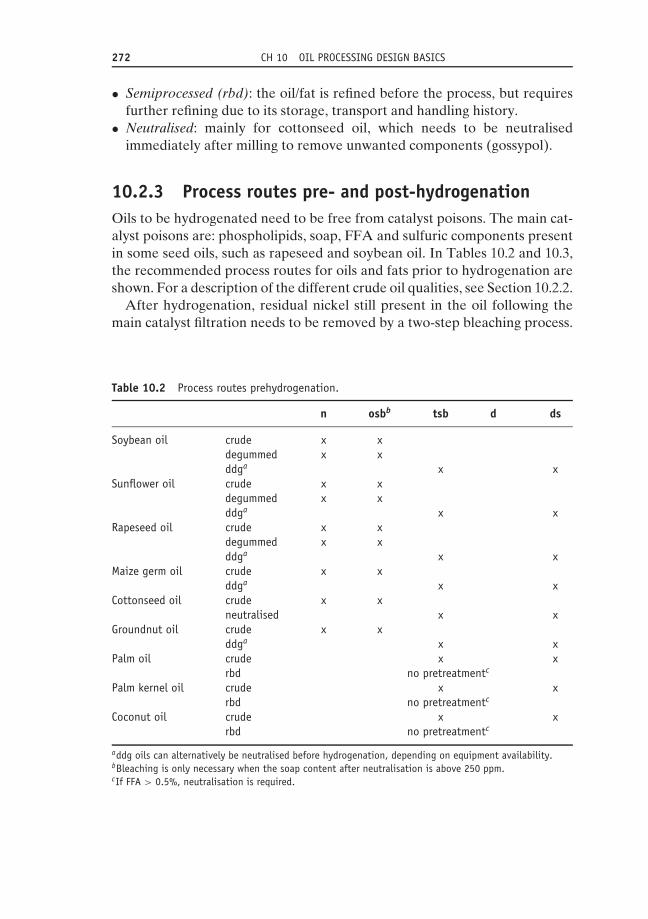
272 CH 10 OIL PROCESSING DESIGN BASICS
• Semiprocessed (rbd): the oil/fat is refined before the process, but requiresfurther refining due to its storage, transport and handling history.
• Neutralised: mainly for cottonseed oil, which needs to be neutralisedimmediately after milling to remove unwanted components (gossypol).
10.2.3 Process routes pre- and post-hydrogenationOils to be hydrogenated need to be free from catalyst poisons. The main cat-alyst poisons are: phospholipids, soap, FFA and sulfuric components presentin some seed oils, such as rapeseed and soybean oil. In Tables 10.2 and 10.3,the recommended process routes for oils and fats prior to hydrogenation areshown. For a description of the different crude oil qualities, see Section 10.2.2.
After hydrogenation, residual nickel still present in the oil following themain catalyst filtration needs to be removed by a two-step bleaching process.
Table 10.2 Process routes prehydrogenation.
n osbb tsb d ds
Soybean oil crude x xdegummed x xddga x x
Sunflower oil crude x xdegummed x xddga x x
Rapeseed oil crude x xdegummed x xddga x x
Maize germ oil crude x xddga x x
Cottonseed oil crude x xneutralised x x
Groundnut oil crude x xddga x x
Palm oil crude x xrbd no pretreatmentc
Palm kernel oil crude x xrbd no pretreatmentc
Coconut oil crude x xrbd no pretreatmentc
addg oils can alternatively be neutralised before hydrogenation, depending on equipment availability.bBleaching is only necessary when the soap content after neutralisation is above 250 ppm.cIf FFA > 0.5%, neutralisation is required.
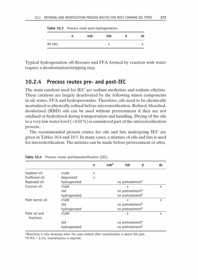
10.2 REFINING AND MODIFICATION PROCESS ROUTES FOR MOST COMMON OIL TYPES 273
Table 10.3 Process route post-hydrogenation.
n osb tsb d ds
All fats x x
Typical hydrogenation off-flavours and FFA formed by reaction with waterrequire a deodorisation/stripping step.
10.2.4 Process routes pre- and post-IECThe main catalysts used for IEC are sodium methylate and sodium ethylate.These catalysts are largely deactivated by the following minor componentsin oil: water, FFA and hydroperoxides. Therefore, oils need to be chemicallyneutralised or physically refined before interesterification. Refined, bleached,deodorised (RBD) oils can be used without pretreatment if they are notoxidised or hydrolysed during transportation and handling. Drying of the oilsto a very low water level (<0.01%) is considered part of the interesterificationprocess.
The recommended process routes for oils and fats undergoing IEC aregiven in Tables 10.4 and 10.5. In many cases, a mixture of oils and fats is usedfor interesterification. The mixture can be made before pretreatment or after,
Table 10.4 Process routes preinteresterification (IEC).
n osba tsb d ds
Soybean oil crude xSunflower oil degummed xRapeseed oil hydrogenated no pretreatmentb
Coconut oil crude x xrbd no pretreatmentb
hydrogenated no pretreatmentb
Palm kernel oil crude x xrbd no pretreatmentb
hydrogenated no pretreatmentb
Palm oil andfractions
crude x x
rbd no pretreatmentb
hydrogenated no pretreatmentb
aBleaching is only necessary when the soap content after neutralisation is above 250 ppm.bIf FFA > 0.1%, neutralisation is required.

274 CH 10 OIL PROCESSING DESIGN BASICS
Table 10.5 Process route post-interesterification (IEC).
n osb tsb d ds
All fats x x
depending on equipment availability, quantities, the quality of an individualcomponent and so on. The process route for a mixture is mainly determinedby its largest component. For a description of the different crude oil qualities,see Section 10.2.2.
Deactivation of the catalyst by water washing and drying is considered to bepart of the interesterification process. Bleaching and deodorisation are a mustafter IEC, in order to remove reaction products such as soap and methyl esters.
10.2.5 Process routes pre- and post-IEETo protect the enzymes from degradation and activity loss, all oils enteringthe process should be of a fully refined quality and free from inorganicacid residues. After IEE, the oils require deodorisation to remove off tastecomponents.
10.2.6 Process routes in dry fractionation and dewaxingThe concentration of phosphatides should be as low as possible beforedewaxing by filtration. This is achieved by neutralisation and bleaching inchemical refining and deep degumming and two-step bleaching in physicalrefining.
Full physical refining is recommended before fractionation. High-temperature deodorisation of the olein may cause a change of melting pointdue to interesterification at high temperatures in the deodoriser.
Tables 10.6 and 10.7 show the recommended process routes for oils andfats that are dry fractionated or dewaxed.
10.3 Oil processing block diagram design10.3.1 Standard oil processing block diagramsThe design of the oil processing block diagram will be based on the processingsequence recommended in Section 10.2. Additional information required todetail the design includes:

10.3 OIL PROCESSING BLOCK DIAGRAM DESIGN 275
Table 10.6 Process route pre fractionation and dewaxing.
n osb tsb d ds
Palm oil crude x xSunflower oil crude x x
degummed x xddg x
Table 10.7 Process route post fractionation and dewaxing.
n osb tsb d ds
Palm oil (fractions) no post treatmenta
Sunflower oil d or ds
aPost-treatment is necessary if during the storage and transport of palmoil fractions the FFA content increases to >0.1%.
• production volumes;• equipment design capacities;• working pattern and operational time;• required flexibility (batch or continuous lines);• crude and refined oil storage requirements.
This section will propose standard oil processing block diagrams based onthe process routes recommendations and required flexibility. These standardblock diagrams are selected based on the most common working practices;different local circumstances may lead to deviating block diagram designs.Later sections will deal with effective equipment capacity and tank parkdesign rules.
10.3.2 Batch and continuous processesThe refining and oil modification processes can be carried out in batch or con-tinuous equipment, while deodorisation can be carried out semicontinuouslyin an intermediate form.
Batch processes are mainly performed within a single piece of equipment;the process steps are sequential in time. The input is discontinuous at the startof the sequence, the output discontinuous at the end.
In continuous processes, the process steps are simultaneous in differentpieces of equipment; both input and output are more or less constantover time.
276 CH 10 OIL PROCESSING DESIGN BASICS
Comparison of batch and continuous processes gives the following mainadvantages and disadvantages.
10.3.2.1 Batch processesMain advantages:
• short product changeover time;• suited for small production lots;• flexible recipe;• simple maintenance;• can be operated manually.
Main disadvantages:
• limited scope for heat recovery;• requires sequence control;• many parallel lines for high capacity (space requirement).
10.3.2.2 Continuous processesMain advantages:
• suited for high-capacity lines (low space requirement);• input/output heat recovery;• simple automation and control;• low manning level.
Main disadvantages:
• long product changeover time;• complex and costly maintenance;• high electrical energy consumption.
Due to economical constraints, only small or specialised refineries will operatemainly with batch equipment (batch size: 5–20 tonnes). Fully continuousplants are used for large runs of the same products: continuous refining ofseed oils on the same site as the seed oil extraction plant, for example. Productchangeover in a continuous plant means a loss of production time; this lossdepends on the average residence time of the oil in the equipment (oil contentdivided by capacity) and the product intermixing specifications. High-capacityflexible refineries consist of continuous neutralisation lines, continuous andbatch bleachers (batch for post-treatment after hydrogenation and/or IEC,for example) and semicontinuous deodorisers. Hydrogenation, IEC andfractionation are almost always batch processes. IEE is a continuous process.
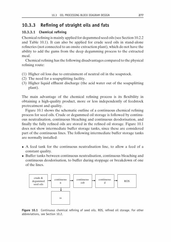
10.3 OIL PROCESSING BLOCK DIAGRAM DESIGN 277
10.3.3 Refining of straight oils and fats10.3.3.1 Chemical refiningChemical refining is mainly applied for degummed seed oils (see Section 10.2.2and Table 10.1). It can also be applied for crude seed oils in stand-alonerefineries (not connected to an onsite extraction plant), which do not have theability to add the gums from the deep degumming process to the extractedmeal.
Chemical refining has the following disadvantages compared to the physicalrefining route:
(1) Higher oil loss due to entrainment of neutral oil in the soapstock.(2) The need for a soapsplitting facility.(3) Higher liquid effluent discharge (the acid water out of the soapsplitting
plant).
The main advantage of the chemical refining process is its flexibility inobtaining a high-quality product, more or less independently of feedstockpretreatment and quality.
Figure 10.1 shows the schematic outline of a continuous chemical refiningprocess for seed oils. Crude or degummed oil storage is followed by continu-ous neutralisation, continuous bleaching and continuous deodorisation, andfinally the fully refined oils are stored in the refined oil storage. Figure 10.1does not show intermediate buffer storage tanks, since these are consideredpart of the continuous lines. The following intermediate buffer storage tanksare normally installed:
• A feed tank for the continuous neutralisation line, to allow a feed of aconstant quality.
• Buffer tanks between continuous neutralisation, continuous bleaching andcontinuous deodorisation, to buffer during stoppage or breakdown of oneof the lines.
crude °ummedseed oils
continuousn
continuousosb
continuousd
ROS
ss
Figure 10.1 Continuous chemical refining of seed oils. ROS, refined oil storage. For otherabbreviations, see Section 10.2.

278 CH 10 OIL PROCESSING DESIGN BASICS
crude °ummedseed oils
batchn + osb
batchd ROS
ss
Figure 10.2 Batch chemical refining of seed oils. ROS, refined oil storage. For other abbrevi-ations, see Section 10.2.
Figure 10.2 shows the schematic outline of a batch chemical process. Thebatch neutralisation and batch bleaching are normally done in the samevessel, followed by batch deodorisation. A buffer tank is installed betweenthe bleaching earth filter and batch deodoriser to improve capacity utilisationof both processes.
10.3.3.2 Physical refiningPhysical refining can be applied for seed oils after deep degumming of thecrude oil. The phosphorus level following the deep degumming process shouldbe below 30 ppm, in order to avoid uneconomically high bleaching earth levelsin the bleaching step. The deep degumming process is preferably carried outin the seed oil extraction plant. In that case, the gums can be recycled to themeal. A deep degumming process for standalone refineries is less attractive,since the gums are microbiologically unstable and should be dried or utilisedimmediately after production.
Figure 10.3 gives an outline of the physical refining process for seed oils(for process buffers, see Section 10.3.3.1). The bleaching step following deepdegumming should be two-step bleaching (see Section 10.2.2), in order tohydrate and agglomerate residual phospholipids with acid and water beforetheir removal with bleaching earth. The deodorisation/stripping temperatureshould be such that FFA are removed and the trans fatty acid level remainsbelow the specified limit (see van Duijn et al., 2006). Figure 10.4 shows theblock diagram of the physical refining process for tropical oils.
crude seed oils
continuousddg
continuoustsb
continuousds
ROS
Figure 10.3 Physical refining of seed oils. ROS, refined oil storage. For other abbreviations,see Section 10.2.

10.3 OIL PROCESSING BLOCK DIAGRAM DESIGN 279
crude & RBD tropical oils
continuoustsb
continuousds
ROS
Figure 10.4 Physical refining of tropical oils. ROS, refined oil storage. For other abbreviations,see Section 10.2.
crude °ummedseed oils
continuousn
ss ROS
batchh
batchtsb
semi-continuous
ds
Figure 10.5 Chemical refining and hydrogenation of seed oils. ROS, refined oil storage. Forother abbreviations, see Section 10.2.
10.3.4 Refining combined with hydrogenationIn the case of batch refining, crude and degummed seed oils require neu-tralisation and bleaching before hydrogenation (see Figure 10.5), resultingin low FFA, phosphorus and soap levels. In continuous refining, bleachingcan be omitted where there is good-quality centrifuge neutralisation, whichresults in low soap levels. In this latter case, the catalyst dosing will be slightlyhigher, but this on-cost will be largely compensated for by the omission of thebleaching step.
Batch two-step bleaching (or an acid treatment followed by filtration) andsemicontinuous deodorisation/stripping are mostly applied after hydrogena-tion. Starting with seed oils, a range of products with different melting pointscan be produced by the process steps sequence of centrifuge neutralisation,partial hydrogenation to various melting points, batch two-step bleaching andsemicontinuous deodorisation/stripping. This sequence is largely applied inthe soybean oil-based refineries in the USA, for example.
In physical refining of deep degummed seed oils and tropical oils, the oilsneed to be two-step bleached and deodorised/stripped before hydrogenation(Figure 10.6). The post-refining sequence is identical with the chemicalrefining route.
10.3.5 Refining combined with interesterificationFigure 10.7 gives the total process sequence for chemical refining, IEC andpost-bleaching followed by deodorisation/stripping. IEC is a batch process.

280 CH 10 OIL PROCESSING DESIGN BASICS
crude &ddgoils
continuoustsb
continuousds
batchh
batchtsb
semiconti-nuous
ds
ROS
Figure 10.6 Physical refining and hydrogenation of ddg seed oils and tropical oils. ROS,refined oil storage. For other abbreviations, see Section 10.2.
crude °ummedseed oils
batchn
ss
batchIEC
batchosb
Semiconti-nuous
dsROS
Figure 10.7 Chemical refining and IEC of seed oils. ROS, refined oil storage. For otherabbreviations, see Section 10.2.
Preneutralisation and post-bleaching are therefore often performed in thesame batch vessel. This vessel should be equipped with a caustic and waterdosing facility, soapstock draining, a recirculation loop and deep vacuumfor drying, a catalyst dosing unit and a dosing system for bleaching earth(multipurpose vessel).
All oil components are already bleached and deodorised before theyenter the interesterification vessel in combined physical pretreatment/IEC(see Figure 10.8). Post-bleaching can still be performed in the multipurposevessel.
crude &ddgoils
continuoustsb
continuousds
batchIEC
batchosb
semiconti-nuous
ds
ROS
Figure 10.8 Physical refining and IEC of ddg seed oils and tropical oils. ROS, refined oilstorage. For other abbreviations, see Section 10.2.

10.3 OIL PROCESSING BLOCK DIAGRAM DESIGN 281
crudetropical
oils
continuoustsb
(Semi) conti-nuous
ds
continuousIEE
(Semi) conti-nuous
dROS
Figure 10.9 Physical refining and IEE of tropical oils. ROS, refined oil storage. For otherabbreviations, see Section 10.2.
IEE is a continuous process; the feedstocks are fully refined materials,though without citric acid dosing after deodorisation. Enzymatically inter-esterified oils need only post-deodorisation/stripping to remove FFA andodour/taste components. This deodorisation can be continuous if it is linkedwith one IEE line, or semicontinuous if it is linked with several lines.Figure 10.9 shows the block diagram for the combination of physical refiningand enzymatic interesterification of tropical oils.
10.3.6 Refining and dewaxingPredewaxing can be combined with deep degumming or neutralisation andis not discussed in this section. Final dewaxing and filtration with filter aidis a continuous process following bleaching. Input/output heat exchange isrequired to reduce heating and cooling energy input.
10.3.7 Refining and fractionationFractionation of palm oil is normally done after full physical refining ofthe oil (see Section 10.2.6). In most fractionation filters, the olein resides inclosed pipes while the stearin is in open contact with the environment. Specialcare should be taken to avoid contamination of the stearin by dirt from theenvironment (high-care zone).
10.3.8 Production of trans-free hard fatsUntil the mid 1990s, partial hydrogenation was the most widely appliedtechnique for increasing the melting point of unsaturated oils and fats. Nextto saturation, hydrogenation inevitably involves cis/trans isomerisation ofsome of the double bonds. Publications in the early 1990s indicated thattrans fatty acids have a negative effect on blood cholesterol and, hence, oncoronary heart disease risk. This resulted in a gradual elimination of partialhydrogenation as an oil modification technique.
The combination of full hydrogenation (iodine value, IV < 2), interesteri-fication and fractionation on a wide variety of feedstocks will produce hardfats with a wide range of melting performances (van Duijn et al., 2006).

282 CH 10 OIL PROCESSING DESIGN BASICS
Liquid seed oils first need full hydrogenation to generate solids. These fullyhydrogenated oils then require interesterification with nonhydrogenated oilsin order to reduce solid levels at high temperatures. These solid levels can befurther reduced by fractionation (see Figure 10.10).
The presence of relatively high solid levels in natural tropical oils createsmore flexibility in process routes. Fractionation of palm oil alone will producea relatively soft stearin with a relatively long tail of the solid phase line. Stearinis as such not optimal for structuring products such as margarine. Fractionationof palm oil (or double fractionation) followed by interesterification with palmkernel oil will produce nonhydrogenated fat phase components with moresuitable solid phase lines. Full hydrogenation of palm oil and palm kerneloil followed by interesterification is an alternative way of obtaining fatcomponents without fractionation.
This combination of techniques (see Figure 10.10) creates a tool forproducing optimal fat phase products. This tool is almost as flexible as partialhydrogenation.
A multipurpose refinery will combine the refining and processing stepsoutlined in the previous sections. The combination of chemical refiningfor degummed seed oils, physical refining for crude seed oils (including adeep degumming process step) and tropical oils with the trans-free hard fatmodification techniques just mentioned is illustrated in Figure 10.11. Thisfigure shows the increase of complexity compared to the combination of
Liquid oils
Tropical oils
Fullhydrogenation
Interesterification
Fractionation
Trans-freehard fats
Figure 10.10 Virtual trans-free modification techniques.

10.4 EFFECTIVE EQUIPMENT CAPACITY 283
CRUDE OILINTAKE AND
STORAGE
DEEP DEGUMMING NEUTRALISATION FULL HYDROGENATION
BLEACHING INTERE STERIFICATION
DEODORISATION FRACTIONATION
STORAGE
transport
Figure 10.11 An oil processing flowsheet, combining the virtual trans-free modificationtechniques with both chemical and physical refining.
refining and partial hydrogenation mentioned in Section 10.3.4 and illustratedby Figure 10.5.
10.4 Effective equipment capacityThe design of an oil processing block diagram is in general based on an annualvolume estimate, corrected for seasonal variations. Equipment manufacturersspecify the capacity of their equipment as an hourly or 24-hours productionvolume. This section gives an estimation of annual production capacities,starting from the hourly capacity as specified by the equipment manufacturer.
First, the effective production time is estimated by the following analysis:
(1) The total time in a year (see Figure 10.12, T) is 365 × 24 = 8760 hours(the extra day every 4 years is not taken into account).
(2) The available production time (A) is total time minus unavailable time.Unavailable time is statutory and religious holidays, weekends, shifts notworked and enforced factory shutdowns.
(3) The used production time (U) is available time minus available unusedtime. Available unused time is time lost because there are no productionorders.
(4) The operational time (O) is used time minus planned non-operationaltime. The planned non-operational time is scheduled maintenance andplanned tests without production.

284 CH 10 OIL PROCESSING DESIGN BASICS
T Total Time
A Available Time Unavailable Time
U Used Time Available Unused Time
O Operational Time Planned Non-Operational Time
P Production Time Routine Production Stoppages
E Effective Time Unexpected Stoppages
Figure 10.12 Effective machine time analysis.
(5) The production time (P) is operational time minus routine productionstoppages. These stoppages are startups and shutdowns, cleaning andbreaks (meals, rest etc.). Startups and shutdowns are important in 5-days-a-week operations; breaks are not applicable in fully automatedplants.
(6) The effective time (E) is operational time minus unexpected stoppages.Unexpected stoppages are unplanned repairs or breakdowns, failures ofmaterial supply, full or empty tanks, absences of operators and so on.
The time difference between total and operational time can be estimatedfrom events that can be planned in advance. The time difference betweenoperational and effective time contains unpredictable events (cleaning, break-downs etc.). Thus the operational efficiency (EO) has been introduced:
EO = E/O × 100% (10.1)
EO is an average over years of experience and depends on type of equipment,operating mode (batch or continuous) and weekly working pattern (5 × 24hours or 7 × 24 hours a week).
The EO given in Table 10.8 can be used as guideline for oil processingdesign.
The estimated annual capacity can now be calculated from the hourlycapacity specified by the equipment manufacturer:
annual capacity = hourly capacity×EO×operational time (tonnes/annum)
(10.2)
Table 10.8 Guideline EO for oil processing design.
EO (%) 5 days a week 7 days a week
Batch equipment 85 85(Semi)continuous equipment 85 95

10.5 TANK PARK DESIGN RULES 285
10.4.1 Example: calculation of effective timesfor 5- and 7-days-a-week operations
10.4.1.1 5 days a week
• A year has 52 weekends of 48 hours.• There are three additional stops of 24 hours for public holidays.• The preventive maintenance stop is 5 days of 24 hours.• Calculation:
◦ total time = 8760 h/a;◦ unavailable unused time = 2368 h/a;◦ planned non-operational time = 120 h/a;◦ operational time = 6072 h/a;◦ effective time all equipment (EO = 85%) = 5161 h/a.
10.4.1.2 7 days a week
• Stops for public holidays: 5 days a year.• Preventive maintenance stop: 6 days of 24 hours.• Calculation:
◦ total time = 8760 h/a;◦ unavailable unused time = 120 h/a;◦ planned non-operational time = 144 h/a;◦ operational time = 8496 h/a;◦ effective time batch equipment (EO = 85%) = 7222 h/a;◦ effective time continuous equipment (EO = 95%) = 8071 h/a.
Note that a continuous refinery running 5 days a week has only 64% of theannual capacity of a continuous refinery running 7 days a week, while theoperational time at 5 days a week is 71% of that at 7 days a week. Thisdifference is caused by the weekly startups and shutdowns due to weekendstoppages.
10.5 Tank park design rules10.5.1 Storage capacityThe oil processing plant will store crude or semiprocessed oils and fatsunloaded in large volumes from ships, trains and trucks. The crude oil tankpark should have sufficient capacity to store the received volume in separateempty tanks. Topping up of partly full tanks can only be allowed if the oilin the tank and the arriving oil are of equal type and quality, and if the

286 CH 10 OIL PROCESSING DESIGN BASICS
arriving oil has been checked and approved for quality and food safety. Shipdeliveries will have an uncertainty around their arrival date and time, leadingto additional buffer storage requirement. At arrival, ships need to be unloadedwithin a restricted time interval in order to avoid penalties. Train deliveriesare normally well planned and have defined time arrival and departure times.Truck deliveries are more flexible but may still have restrictions due to trafficconditions, limited circulation at weekends and so on.
Oil processing plants on the same site as the oil mill will store crude oils tomatch differences in capacities and to buffer for upstream breakdowns.
Oil Processing plants will store oils in between processing steps to matchdifferences in capacities and to buffer for upstream and downstream break-downs. The storage capacity for breakdown buffering should be sufficient tobuffer the volume of one production shift (8 hours’ production).
Fully refined oils are stored after deodorisation to match differences incapacities or working patterns of the oil processing plant and its customers,to buffer for upstream breakdowns, to deliver full tank-car loads and to storecomponents in case of blends delivery. Fully refined oils and fats should bestored for as short an amount of time as possible in order to minimise qualitydowngrading.
A minimum of two tanks per oil type should be used for continuousproduction lines; this allows one tank to receive the deodorised oil whiletrucks are loaded from the other one, and makes complete emptying duringchangeover from one tank to the other possible.
Multiproduct sites will normally make flexible use of the available tanks.Spare tanks will allow regular emptying. Topping up of a remaining quantityof oil in a storage tank with a new batch of identical product is only possibleif the following topping-up rules are applied:
• The previous batch in the tank should not be too old (more than a fewdays).
• The previous batch should have a bland taste.• The chemical and physical parameters of the previous batch should be
within specifications.• The tank must be regularly emptied, so as to ensure traceability and avoid
residues with a very long residence time.
10.5.2 Degradation during storageOils and fats will slowly deteriorate during storage due to chemical reactions.Storage also introduces the risk of downgrading through intermixing orcontamination. This results in a loss of quality and/or value of the oil. Themain causes of degradation are:

10.5 TANK PARK DESIGN RULES 287
• Hydrolysis: decomposition of triacylglycerol to FFA and diacylglycerolfurther to monoacylglycerol.
• Oxidation: reaction with oxygen from the air.• Intermixing with other types or qualities of oil.• Contamination by chemicals or impurities.
10.5.2.1 HydrolysisThis chemical reaction requires dissolved water. The rate increases withtemperature and the reaction is autocatalysed by FFA. Figure 10.13 shows thehydrolysis of palm oil, saturated with dissolved water, as a function of time,temperature and the initial FFA concentration (Hilder, 1968). This graphshows that minimum oil loss by hydrolysis is obtained at low temperature(storage temperature should be at least 5–10 ◦C above melting point in orderto avoid fractionation), low initial FFA content and short storage time. Also,the dissolved water concentration in the oil should be kept as low as possibleby avoiding water addition from steam blowing of pipes, rainwater throughopen manholes, leaking heating coils and so on.
10.5.2.2 OxidationContact of oils and fats with oxygen present in the atmosphere causes chemicalchanges in the product, which downgrades its quality (through formation ofhydroperoxides, which further react to aldehydes and ketones). Some of theeffects of oxidation may be rectified by refining, which involves some extraprocessing, and therefore extra cost. However, the deterioration can be sosevere that it can never be fully rectified. Much is to be gained by reducing
0
0.5
1
1.5
2
0 2 4 6 8
Time (weeks)
% F
FA in
crea
se p
er %
initi
al F
FA
37 deg.C50 deg.C60 deg.C70 deg.C80 deg.C100 deg.C
Figure 10.13 Free fatty acid (FFA) increase over time as a function of temperature and initialFFA concentration (Hilder, 1968).

288 CH 10 OIL PROCESSING DESIGN BASICS
the air contact, and this principle is the basis of several tank design rules (seeSection 10.5.3). Oxidation proceeds more rapidly as temperature increases,so each operation must be carried out at the lowest practicable temperature.The rate of oxidation is greatly increased by the catalytic action of copper orcopper alloys, even when trace amounts are present. Because of this, copperand copper alloys must be rigorously excluded from the systems. Other metals,such as iron, also have a catalytic effect, although it is less than that of copper.
The oxidation sensitivity depends on the level of unsaturation of the oil:highly unsaturated oils like soybean and rapeseed oil oxidise more easily thanmore saturated tropical oils like palm and coconut oil.
10.5.2.3 Intermixing with other oilsIntermixing with other types or different qualities of oil may lead to a seriousvalue loss. In most cases, the mixture obtains the value of the cheapestcomponent, if the intermixing level is above a generally accepted technicallyunavoidable limit. In some cases, the mixture may even downgrade to thevalue of rework. The risk of intermixing can be minimised by tank dedication,zoning of piping, adequate cleaning of tanks and pipes before productchangeover and proper topping-up procedures.
10.5.2.4 Contamination by chemicals or impuritiesContamination by stored chemicals can be avoided through full separationof oil storage and chemicals (including fatty acids) storage. Cleaning withfood-grade chemicals followed by flushing with water and oil should beapplied for new tanks and following tank repairs. Pumps and tank stirrersshould be placed in such a way that lubricant oil cannot come in contact withthe product. Tanks should be heated with low-pressure steam or hot water;thermal heating oil should be excluded.
All openings to the tanks environment (like manholes, unloading connec-tions, hoses etc.) must be kept closed when not in use, so as to avoid theentrance of impurities such as sand, bird droppings or even animals.
Impurities in the crude oil may settle with water to form tank bottoms.When processed, these tank bottoms result in high refining losses. In somecases, they cannot be processed and must be discharged as chemical waste.Tank bottoms can be avoided by a proper design of the oil outlet, combinedwith controlled agitation.
10.5.3 Tank design rules10.5.3.1 Tank shape and material of constructionThe most suitable shape is the vertical, circular cross-section tank with self-supporting fixed roof, the latter preferably conical in shape (see Figure 10.14).

10.5 TANK PARK DESIGN RULES 289
Sample
ManholeAgitator
VentDip Point
Oil Inlet
Coil Inlet/Outlet
Inspection
Oil Outlet
VerticalCoil
Figure 10.14 The basic design of a crude oil storage tank.
Tall, narrow tanks are preferred as they minimise contact between the oils orfats and oxygen from the air.
The bottoms of large crude oil tanks should be sloped (with a sump witha separate outlet) to facilitate draining. The bottoms of refined oil storagetanks should be conical, to allow complete emptying.
All openings (manholes, inlets, outlets etc.) should be made such that theycan be locked and/or effectively sealed.
All materials used in the construction of tanks and for ancillary equipment(including heating facilities) should be inert to oils and fats and should besuitable for use in contact with food.
Stainless steel is the preferred material for the construction of tanks.Stainless steel will never cause an iron contamination and stainless-steeltanks can be used for all types of oils and fats.
Mild steel tanks can be used for the storage of crude oils and of fully refinedliquid oils at low temperature, provided that the protective layer formed bypolymerised oil is not removed or damaged by water cleaning.
Copper and its alloys (brass, bronze, gun metal etc.) must never be used incontact with oils and fats.
Temperature gauges containing mercury should not be used, since theymay break and lead to mercury contamination of the oil.
Glass equipment and glass sample bottles should be avoided in situationswhere breakage might lead to contamination.

290 CH 10 OIL PROCESSING DESIGN BASICS
10.5.3.2 Tank heating
All tanks for solid or semisolid oils and fats (including liquid oils in low-temperature climates) should be provided with heating coils so that theproduct is liquid and homogenous when transferred or unloaded. Heatingcoils should be made of stainless steel.
Heating by hot water (about 90 ◦C) is the generally preferred system, as itis the least likely to cause local overheating.
If steam heating is used, the steam pressure should not exceed 2.5 bar(maximum temperature 127 ◦C). The heating coils’ position should enableeasy cleaning of the tank bottom. At least one vertical coil should be provided,to create a channel of melted fat from the top to the bottom of the tank andthus prevent any overpressure caused by the volume increase during meltingof solid fats or by steam pressure from a leaking coil. This also prevents thecollapse of the tank through pumping out of oil while the top of the tankcontent is still solid.
As a guideline: for insulated tanks with hot water, a coil area of between0.1 m2 per tonne of tank capacity (for small tanks) to 0.05 m2 per tonne oftank capacity (for large tanks) is sufficient to heat the contents of the tank at5 ◦C per day or to melt solidified fat at 5% per day.
For the melting solidified of fats, hot water heating requires more time thansteam heating.
10.5.3.3 Tank insulation
Storage tanks should preferably be insulated (including the roof), particularlyin moderate and cold climates. Heated tanks should always be insulated.Insulation must be designed to avoid the absorption of oil or water in theinsulation material.
10.5.3.4 Avoiding air contact
Filling can be done from the bottom or via a dip pipe from the top to thebottom. When pipe blowing is applied, filling should be from a pipe at thetop, with the opening pointing to the tank wall, so as to obtain an oil flowalong the tank wall downwards. This avoids splashing and aeration of the oil.
Nitrogen blanketing is generally not recommended for crude and partlyprocessed oils, but can be applied for fully refined oils in longer (>3 days)storage.
It is recommended that storage tanks for crude oils and fats be providedwith proper agitation (e.g. side-entry stirrers or ejector mixers) in order toprevent settling of impurities during storage. The stirrers have to be designedand operated in such a way that air entrainment and the formation oftank bottoms are effectively avoided during storage. This can be achievedby a side-entrance stirrer positioned near the bottom of the tank running

10.6 DESIGN ESTIMATES FOR UTILITIES CONSUMPTIONS AND EFFLUENT PRODUCTION 291
intermittently. The stirrer should be switched off if the oil reaches a low levelclose to the top of the stirrer to avoid air entrainment.
Tanks for fully refined oils and fats should not be stirred.
10.5.4 Piping design rules10.5.4.1 MaterialsMild steel is acceptable for all crude and semirefined oils and fats pipelines,though stainless steel is preferable.
Flexible hoses that are used to connect pipelines during loading andunloading must be of inert material, be suitably reinforced and be of such alength and design as to make cleaning easy. Exposed ends should be cappedwhen not in use. Couplings for flexible hoses should be of stainless steel oranother inert material.
10.5.4.2 Insulation and heatingPipelines used for oils and fats which may solidify at ambient temperaturesshould preferably be lagged and also be provided with heating, for exampleby steam tracing lines or electrical heating tape. The pipe temperature shouldnot exceed 110 ◦C, in order to avoid overheating of the oil or fat.
10.5.4.3 LayoutIt is preferred to have dedicated lines for groups of oils of a similar fatty acidcomposition when different types of oils and fats are stored (as e.g. palm oil,lauric oils and liquid oils).
The layout of the pipelines should be such that draining by gravity is aidedand not hindered. Horizontal pipes should have a slight slope downwards inthe direction of the flow. Blowing of pipes should always be from high to low;if needed, a small-diameter pipe can be used to route the blown oil upwards.
A pigging system can be used for line clearing when different types of oilsand fats are transported via one pipeline.
10.6 Design estimates for utilities consumptionsand effluent production
10.6.1 IntroductionOil processing processes require such utilities as:
• Energy in the form of steam, electricity and hot water.• Water for cooling and cleaning.

292 CH 10 OIL PROCESSING DESIGN BASICS
• Compressed gases such as air and nitrogen for control purposes, oil protec-tion and blowing.
The processes produce waste in the form of:
• Liquid effluent from neutralisation/soapsplitting and deodorisation.• Solid waste from bleaching and dewaxing.• Exhaust gases from deodorisation.
The quantification of utilities consumptions and effluent production requiresdetailed equipment characteristics, environmental parameters (such as cool-ing water temperature) and oil quality data. These will not be available inthe early phase of the design process. Estimated utilities and effluent datamay be required to help justify a project and the design principles of a utilityinstallation. This chapter will supply estimates based on best-practice datawhich can be used for first-design purposes.
10.6.2 Utilities10.6.2.1 HeatingDuring processing, oil needs to be heated at the following stages:
(1) At arrival: heating to storage temperature (for oils which are stored inheated tanks), in case of a temperature drop during transport.
(2) In the tank park: to compensate for heat losses during storage in heatedtanks.
(3) From storage temperature to first process temperature (for neutralisation,95 ◦C; for bleaching, 70–120 ◦C): continuous processes may have heatrecovery; the oil output has a temperature lower than the processtemperature.
(4) In chemical refining: from neutralised oil storage temperature to bleach-ing temperature.
(5) In hydrogenation: oil needs to be heated to the temperature at whichthe reaction starts (120–150 ◦C); the reaction itself produces heat.
(6) In IEC: the oil must be heated to drying temperature (max. 110 ◦C); theIEE temperature is relatively low (70 ◦C) and no additional heating isrequired.
(7) In dewaxing after bleaching: the oil needs to be heated from dewax-ing temperature to buffer temperature, or directly to deodorisationtemperature.
(8) From bleached oil buffer temperature to deodorisation temperature: thisis by far the largest temperature difference; heat recovery is normallyapplied.

10.6 DESIGN ESTIMATES FOR UTILITIES CONSUMPTIONS AND EFFLUENT PRODUCTION 293
(9) In fractionation: the stearin needs to be melted and heated to 15 ◦Cabove melting point.
(10) In refined oil storage: the temperature needs to be maintained at 15 ◦Cabove melting point.
The heating in steps 1–7 is or by condensing steam or hot water. The hightemperature in deodorisation is reached through a closed high-pressure steamloop heated by a light fuel oil, a gas-fired boiler or high-pressure steam. Hotwater is preferred for heating after deodorisation (steps 9 and 10).
The heat loss of a storage tank can be calculated by means of the overallheat transfer coefficient:
� = U.A.(�T) (10.3)
where � is heat loss (W), U is the overall heat transfer coefficient (W/m2 ◦C),A is the surface area through which the heat is transmitted (m2) and �T is thetemperature difference between the oil in the tank and the ambient air (◦C).
For a first estimate, the area of the tank walls plus roof can be taken as:
A = 4.8V2/3 (10.4)
where V is the total tank volume.The overall heat transfer coefficient for this area can be taken as:
U (unlagged) = 7W/m2 ◦C (10.5)
U (lagged) = 1W/m2 ◦C (for a lagging thickness of 50mm) (10.6)
This assumes that the tank is in regular use (on average 50% full). The tem-perature difference �T is the difference between the average tank contentstemperature and the average ambient temperature in the tank farm area.
The mass of steam required to heat 1 tonne of oil is given by the relation:
Msteam = Coil.�T.1000.(1 + X/100)/Csteam (10.7)
where Msteam is the mass of steam per tonne of oil in kg/tonne, Coil is thespecific heat of the oil in kJ/(kg ◦C), �T is the temperature difference in ◦C,X is the relative heat loss to the environment in % and Csteam is the specificheat of steam in kJ/kg.
The specific heat of oil is temperature dependent and varies from2.0 kJ/(kg ◦C) at 20 ◦C to 2.5 kJ/(kg ◦C) at 200 ◦C.
The specific heat of steam is the heat released by condensation andfurther cooling of the condensate. For low-pressure steam, this is around2200 kJ/kg.
294 CH 10 OIL PROCESSING DESIGN BASICS
The light fuel oil consumption to heat oil in a deodoriser via a closedhigh-pressure steam circuit is given by:
Mfuel = Coil.�T.(1–Y/100).(1 + X/100)/(Hfuel.Eboiler/100) (10.8)
where Mfuel is the mass of fuel required to heat 1 tonne of oil in kg/t, Coil is thespecific heat of oil in kJ/(kg ◦C), �T is the difference between deodorisationtemperature and oil inlet temperature in ◦C, Y is the heat recovery in %, X isthe relative heat loss to the environment in %, Hfuel is the heat of combustionof light fuel oil in kJ/kg and Eboiler is the boiler efficiency in %. The heat ofcombustion of light fuel oil (Hfuel) is 42 000 kJ/kg.
10.6.2.2 Open steam and vacuumOpen steam is used in the deodorisation process to remove volatile com-ponents by stripping. The mass of open steam per tonne of deodorised oildepends mainly on the oil temperature and vacuum pressure. Deodoriserconfiguration will have a secondary effect.
In the refining process, vacuum is used for drying (after neutralisation, dur-ing bleaching, before interesterification) and degassing (to evacuate hydrogenfrom a hydrogenation vessel and for deaeration before deodorisation), andto enhance the stripping effect of open steam in deodorisation. The vacuumpressure for drying after neutralisation, during bleaching and during degassingis relatively high (100 mbar). This can be generated by the combination of acondenser and an ejector set or vacuum pump for the noncondensable gases.Drying before IEC requires a pressure of around 20 mbar, which necessitatesa booster between the interesterification vessel and condenser to compressthe vapours from 20 mbar to condenser pressure.
The pressure in deodorisation is normally between 2 and 6 mbar. Such apressure can be obtained in one of two ways:
(1) By compressing the deodoriser vapours to condenser pressure using onebooster or two boosters in series. The motive steam flow of these boostersis between 2 and 4 times the open steam flow of the deodoriser.
(2) By condensing at a very low temperature (around −20 ◦C). Thedeodoriser steam freezes on the coils of the condenser (dry condensing).The very low temperature of the coolant inside these coils is producedby a cooling compressor driven by electrical energy.
The booster system consumes much more steam, the dry condensing systemslightly more electricity. The total energy balance is in favour of the drycondensing system.
10.6.2.3 Electrical energyGeneral electricity use is through consumption by pumps, stirrers, electricaltracing and heating, lighting and the process control system.

10.6 DESIGN ESTIMATES FOR UTILITIES CONSUMPTIONS AND EFFLUENT PRODUCTION 295
Specific machines with relatively high electricity consumptions are:
• Centrifuges in deep degumming and neutralisation.• Cooling compressors in dewaxing, fractionation and dry condensing.• Cooling water circulation pumps and cooling towers.• Vacuum pumps.
10.6.2.4 Cooling waterIn oil refining, the refined oil will leave the site at more or less the sametemperature as that at which it entered the site. Hence the net effect ofheating to process temperatures (after heat recovery) should be compensatedfor by cooling.
Cooling to temperatures slightly above ambient can be achieved by circu-lating the cooling water that passes the process heat exchangers directly overa cooling tower.
Cooling to temperatures slightly above the nearby open-water (river, lakeor sea) temperature can be achieved by circulation of open water directlythrough the process heat exchangers. To minimise the risk of pollution andcorrosion of the process heat exchangers, it is preferable to cool indirectly. Aclosed loop that passes the process heat exchangers will exchange heat withopen water in a secondary heat exchanger.
In oil modification, the temperature of the product leaving the site may bedifferent (in general higher) than that of the product entering the site.
10.6.2.5 GasesCompressed air is mainly used for control purposes as a driving gas forcontrolling valves. Compressed air is sometimes used to blow filter cake atlow temperature after dewaxing. It is not recommended to use air blowing athigh temperatures after bleaching, because of the fire risk.
Compressed nitrogen has several applications:
• As a gas blanket in storage tanks of sensitive oils, to reduce oxidation.• To blow filter cake after bleaching and catalyst filter cake after hydrogena-
tion.• As sparging gas in the outlet pipeline of a deodoriser, to reduce the risk of
air entrainment.• To blow pipelines.• As a safety gas in hydrogenation (Section 10.7.4.1) and deodorisation
(Section 10.7.3.3).
Nitrogen can be delivered as liquid nitrogen in containers, or else can beproduced onsite by pressure swing adsorption or fractional distillation ofliquid air. A reduced oxygen level in air due to the leakage of nitrogen inside

296 CH 10 OIL PROCESSING DESIGN BASICS
closed areas may lead to oxygen depletion, resulting in loss of consciousnessand even death (see Section 10.7.5.2).
Hydrogen is used in the hydrogenation process. Hydrogen can be producedonsite by gas reforming or electrolysis. It can also be transported to thesite as high-pressure gas (200 bar) and reduced to working pressure in apressure-reduction station.
10.6.3 Effluent10.6.3.1 Liquid effluentThe following more or less constant liquid effluent flows are the result of oilprocessing operations:
• Acid water from soapsplitting of soapstock from neutralisation. This low-pHacid water is, before discharge or further treatment, neutralised with sodiumhydroxide to obtain a pH around 7. Washwater from neutralisation or IECcan be added to the flow either before soapsplitting or after soapsplittingbut before neutralisation. The neutralised effluent flow contains sodiumsulfate, phosphates, some residual fatty matter, metals or metal compoundsand organic residues, depending on the processed oil type. The total effluentflow is more or less equal to the sum of all process input flows (dilution waterof chemicals, washwater, bowl flush water of centrifuges etc.). Sometimes,cooling water is added to the neutralised effluent flow to reduce the sodiumsulfate concentration to below a critical limit, in order to avoid degradationof concrete sewer pipes.
• The bleed of the alkaline recirculation system or the melted condensate ofa dry condensing system. The bleed of the alkaline recirculation systemrequires acidification to recover the fatty matter. The total effluent massflow is more or less equal to the sum of the open steam flows and thebooster/ejector motive steam flows.
Incidental liquid effluent discharges can occur due to:
• floor cleaning;• equipment or tank cleaning;• rainwater from the inside of closed tank farm bunds.
Fat-containing flows should pass a fat trap, to avoid blocking of sewer pipesby accumulated fat.
10.6.3.2 Solid wasteThe main waste discharged in an oil processing operation is spent bleachingearth. The volume and composition of spent bleaching earth depends strongly

10.6 DESIGN ESTIMATES FOR UTILITIES CONSUMPTIONS AND EFFLUENT PRODUCTION 297
on the type and quality of the bleached oil. The following components maybe found in spent earth:
• Moisture: after steam blowing of the cake with dry steam, the moisture levelwill be limited (<10%). Higher moisture levels may occur in the case ofhot water treatment (up to 50%) or water spraying to prevent autoignition.
• Oil/fat: this will vary between 20% for well-blown vertical leaf filters to 50%for nonblown cakes. In further treatment, the fatty matter may be valuedas acid oil or as a source of energy. It may also create inconveniences suchas self-ignition, and mineral nitrogen consumption in the case of biologicaldegradation.
• pH: the (water phase) pH of spent earth will normally be low, due to theacid activation of the fresh earth and the residues of phosphoric or citricacid from acid pretreatment.
• Active carbon: bleaching earth may contain active carbon, used for theadsorption of polycyclic aromatic hydrocarbons (PAHs). Disposing ofspent earth that contains active carbon is in general not a problem; infact, in energy recovery applications the carbon will make a positivecontribution. However, in some applications carbon may have a negativeinfluence. Therefore, the waste user should be informed when carbon ispresent.
• Polycyclic aromatic hydrocarbons (PAHs): assuming a crude coconut oilthat contained 40 ppb heavy PAH has been treated with 0.2% carbon and0.8% earth, and the spent earth from coconut oil bleaching is 20% of thetotal spent earth mixture, the final PAH content of the spent earth will beabout 800 ppb.
• Pesticides: pesticides are hardly adsorbed on bleaching earth (with theexception of pirimiphos-methyl); the pesticide content of spent earth isnormally negligible.
• Impurities: spent earth will contain colour components, soaps, salts and soon, on the parts-per-million level.
• Nickel: after the removal of the Ni catalyst from the hardened oil byfiltration, the oil will contain a maximum 5 ppm nickel. Adsorption on tobleaching earth may lead to nickel contents of up to 2000 ppm.
• Other heavy metals: after agglomeration, other heavy metals present in theoil (Cr, Cu, Pb, Zn etc.) will be concentrated on the earth. The total levelof heavy metals (excluding Ni) will normally not exceed 100 ppm.
• Calorific value: the calorific value of a normally blown filter cake, includingmoisture, is relatively low (around 10 000–15 000 kJ/kg for a steam-blowncake).
In the past, disposal of spent bleaching earth was only a minor problem inoil refining. After defatting by caustic or hexane extraction to recover acid

298 CH 10 OIL PROCESSING DESIGN BASICS
oil, the residue could be dumped on public discharges or used as landfill.Sometimes the earth disposal even created financial revenue, due to the valueof the recovered acid oil. The oil refiner ceased to be liable for damage causedby the spent earth once the waste had been removed from their site.
Today, disposal of spent earth is an important problem in oil refining, asa result of the increased interest in and concern for environmental matters.Spent bleaching earth is considered to be an industrial waste, which means thattransport and treatment are strictly regulated and controlled. The restrictionin disposal outlets, the increase of administration costs and the use of morecostly transport and treatment methods have increased the disposal costs.The main disposal outlets are:
• Animal feed: this application is limited to earth that is low in contaminantlevels (PAH adsorbed by active carbon, nickel from bleaching after hydro-genation etc.) and is restricted to refineries that are fully linked to an oilmill (processing the same oil).
• Agricultural recycling: direct recycling on agricultural land is not recom-mended. The preferred route is to add spent earth to other organic wasteand then compost it.
• Incorporation in building materials: in this application, the inert part ofthe spent bleaching earth is incorporated in cement, bricks or expandedclay. During the fabrication process, the organic part of the earth is burnt,contributing to the energy needed for the process.
Spent filter aid from dewaxing and inactive hydrogenation catalyst willnormally have a residual value, due to the sunflower oil or nickel content.
10.6.3.3 Exhaust gasesThe noncondensable gas outlet of the vacuum unit of deodorisation is themain source of odorous gases. Other sources are the soapslitting area, acidoil storage and crude oil storage of smelly oils (coconut oil and fish oil).Reduction of odours can be obtained by passing the gasses through a waterscrubber or a biological filter.
10.6.4 Utility consumption and effluentdata per process
10.6.4.1 StorageThe steam consumption of storage tanks of different capacities is calculatedusing Equations 10.3–10.8 and the following assumptions:

10.6 DESIGN ESTIMATES FOR UTILITIES CONSUMPTIONS AND EFFLUENT PRODUCTION 299
• The tank is lagged and the heat transfer coefficient is 1.0 W/m2 ◦C.• The tank is on average half full with oil during the effective time.• The temperature of the oil stored in the tank is 50 ◦C (e.g. palm oil). The
oil enters the tank at storage temperature. The yearly average ambienttemperature in the tank park area is 10 ◦C.
• The tank is effectively used for 8000 hours per year. It is empty and notheated for the remainder of the year.
• The tanks are completely filled 12 times per year.
Table 10.9 shows the average steam consumption per tonne of stored productrequired to keep oil at storage temperature. The calculations are made fortanks with storage capacities of between 100 and 5000 tonnes. Storing oil ina single large tank always results in a lower steam use per tonne of productthan storing the same amount of oil in two smaller tanks. For example, storing60 000 tonnes per annum of palm oil in one 5000 tonne tank uses 60% of theheating energy required to store the same amount of oil in five tanks of 1000tonnes each.
The electricity consumption per tonne of stored oil varies between 5 and10 kWh, depending on the frequency of pumping and the use of stirrers.An additional 5 kWh/tonne should be added if electrical tracing of pipes isapplied.
10.6.4.2 Refining processesTable 10.10 shows, for each refining process step, the estimated utilityconsumptions and liquid effluent or solid waste productions per tonne
Table 10.9 Heating energy requirement to keep oil in storage tanks at storage temperature.
Tin 50.0 C Latent heat of steam 2250 kJ/kgTout 10.0 C 1 kW = 1.60 kg/h steamDT 40.0 C Effective time 8000 h/yearHTC = 1.0 W/m2C No batches per year 12
Oilcontent
Tankvolume
Effectivesurface
Heatloss
Heatingsteam
Annualsteam use
Steam useper t product
tons m3 m2 kW kg/h t/y kg/t
100 122 118 4.73 7.6 61 50200 244 188 7.51 12.0 96 40500 611 346 13.83 22.1 177 29
1000 1222 549 21.95 35.1 281 232000 2444 871 34.84 55.7 446 195000 6111 1604 64.18 102.7 821 14

300 CH 10 OIL PROCESSING DESIGN BASICS
Tabl
e10
.10
Esti
mat
edut
iliti
esco
nsum
ptio
nsan
dliq
uid
effu
ent
orso
lidw
aste
prod
ucti
ons
per
tonn
eof
proc
esse
doi
l.
Proc
ess
Uti
litie
san
def
flue
ntpe
rto
noi
lpro
cess
ed
Stea
mlig
htfu
eloi
lEl
ectr
icit
yto
tale
nerg
yco
olin
gw
ater
Nitr
ogen
liqui
def
fluen
tso
lidw
aste
kgkg
kWh
Mj
m3
m3
m3
kg
Deep
degu
mm
ing
(ddg
)55
1517
52
Cent
rifu
gene
utra
lisat
ion
+so
apsp
litti
ng(c
n+
ss)
100
1025
63
0.2
Batc
hne
utra
lisat
ion
(bn)
150
635
24
0.4
Blea
chin
g(o
sban
dts
b)60
615
42
45-
30De
wax
ing/
win
teri
sati
on(w
i)30
1512
03
10-2
0Ba
tch
deod
oris
atio
n(d
)28
020
688
61
0.14
Sem
icon
tide
odor
isat
ion
(dan
dds
)-w
ith
alka
line
reci
rcul
atio
n14
08
1870
916
10.
14-w
ith
dry
cond
ensi
ng30
820
474
51
0.03
Cont
ideo
dori
sati
onw
ith
dry
cond
ensi
ng(d
and
ds)
253
1724
25
10.
03

10.7 OCCUPATIONAL SAFETY BY DESIGN 301
of processed oil. The following inputs are used for the deodoriser cal-culations:
• batch deodorisation:
◦ deodorisation temperature = 180 ◦C;◦ no heat recovery;◦ deodorisation pressure = 5 mbar;◦ condenser water outlet temperature = 32 ◦C.
• semicontinuous deodorisation:
◦ deodorisation temperature = 240 ◦C;◦ heat recovery = 40%;◦ deodorisation pressure alkaline recirculation = 5 mbar;◦ condenser water outlet temperature = 32 ◦C;◦ deodorisation pressure dry condensing = 3 mbar.
• continuous deodorisation:
◦ deodorisation temperature = 240 ◦C;◦ heat recovery = 80%;◦ deodorisation pressure dry condensing = 1.5 mbar.
The calculations show that the total energy for semi continuous deodorisa-tion with alkaline recirculation is almost 3 times as high as the total energyfor continuous deodorisation with dry condensing.
10.6.4.3 Modification processesThe estimated utilities consumptions and liquid effluent and solid wasteproductions for the oil modification process are given in Table 10.11. Thistable shows a significant lower total energy use for IEE than for IEC. Theinactive spent catalyst is not given as a solid waste because of its relative highvalue due to its nickel content.
10.7 Occupational safety by design10.7.1 IntroductionOil processing operations are carried out under conditions that may introduceoccupational safety hazards: high temperature, high pressure or vacuum, inhigh buildings, sometimes using aggressive chemicals, with a risk of fireor explosions and so on. The design of the installation should addressthese occupational safety risks and contribute to a zero-accidents workingenvironment. A structured and systematic examination of the existing ordesigned process should be carried out to identify and evaluate problems that

302 CH 10 OIL PROCESSING DESIGN BASICS
Tabl
e10
.11
Esti
mat
edut
iliti
esco
nsum
ptio
nsan
dliq
uid
effu
ent
orso
lidw
aste
prod
ucti
ons
per
tonn
eof
proc
esse
doi
l.
Proc
ess
Uti
litie
san
def
flue
ntpe
rto
noi
lpro
cess
ed
Stea
mLi
ght
fuel
oil
Elec
tric
ity
Tota
lene
rgy
cool
ing
wat
erNi
trog
enLi
quid
efflu
ent
Solid
was
teKg
kgkW
hM
jm
3m
3m
3kg
Hyd
roge
nati
on(h
)55
1517
52
3Ch
emic
alin
tere
ster
ifica
tion
incl
udin
gpo
stbl
each
ing
and
soap
sopl
itti
ng(i
ec+
b+
ss)
150
635
24
30.
210
Enzy
mat
icin
tere
ster
ifica
tion
(iee
)
221
520
0.5
0.66
Frac
tion
atio
n80
2526
63

10.7 OCCUPATIONAL SAFETY BY DESIGN 303
may represent risks to personnel or equipment. Hazard and operational study(HAZOP) is such a structured approach (Tyler et al., 2008). In HAZOP, aprocess flow diagram is examined in detail, specifying its design intention,possible deviations, feasible causes and likely consequences. HAZOP studiesshould be carried out by local teams on actual design details or in existingplants. This chapter cannot and will not replace these local HAZOP studies;rather, it provides an overview of process design-related hazards, which canbe used as one of the inputs for these local studies.
The basis of all safety systems is documentation, education and continuousimprovement. All safety procedures should be well documented, operatorsand contractors should be trained and accidents and near accidents should beevaluated in order to produce improved procedures.
10.7.2 General hazardsThe following hazards are not directly process-related but do belong to themain causes of accidents in oil processing operations:
• Slippery floors: spillage of oils and fats or fatty vapours will result in an oil orfat film on the surfaces of floors, gangways and staircases inside the refinerybuildings, as well as on roads in the direct surroundings. Slipping andfalling by operators, contractors and visitors may lead to serious injuries.Proper selection of surface material, frequent cleaning, antislip safety shoesand mandatory use of handrails will reduce this risk. Open floor gratingwill minimise slipping but can lead to more serious injuries, and frequentcleaning of the grating is required to avoid fouling. Fouled grating willrapidly transfer flames between floors if there is a fire.
• Burns from hot water and steam: pipes transporting hot water and steamare normally well insulated. Insulation should be properly reinstalled afterpipe repairs. The following provide risk of contact with hot water andsteam:
◦ exposure during deblocking of pipes using steam or hot water;◦ cleaning of floors or equipment using hot water (risk of getting hot water
in shoes or boots);◦ steam or hot water from steam traps, overpressure releases and overflow
of closed containers.
• Falling from height: refinery buildings, structures around equipment(deodorisers) and tanks are all high. Gangways are normally protected byhandrails, but operators or contractors may have to work on unprotectedhigh surfaces during maintenance or construction work. Fall-preventionequipment (such as safety harnesses) should be used if secure fencing isnot practical. Also, objects may fall from height and cause serious injuries.

304 CH 10 OIL PROCESSING DESIGN BASICS
Removal of loose objects and the use of helmets to protect operators,contractors and visitors will reduce this risk.
• Noise: high noise levels may occur close to rotating machines, during(steam) blowing operations and at the discharge of self desludging cen-trifuges. As far as possible, noise should be reduced at the source throughbetter design and sound-protection walls. In normal practice, noise cannotbe fully eliminated, and operators, contractors and visitors should wear earprotection, such as earplugs or earcaps.
• Eye protection: spillage of chemicals, dust and aggressive vapours maycause eye damage. Use of proper safety glasses will protect against this.
10.7.3 Main occupational hazards of oil refining10.7.3.1 Neutralisation and soapsplitting
• Centrifuge vibration: strong vibrations must be prevented in order to avoiddamage to the centrifuge bearings. Excessive vibrations can eventually leadto the centrifuge becoming disconnected from its support and starting to‘walk’. Centrifuge disc stacks rotate at a high rotation speed (>4000 rpm),resulting in a high rotation energy. They will continue to rotate for a relativelong period (around 1 hour) after a power shutdown or disruption, movingthe centrifuge through the building and causing serious damage. Regularmaintenance and vibration control will eliminate this risk.
• Chemicals: strong chemicals are used in the neutralisation and soapsplittingprocess. Direct contact with these chemicals should be avoided by followingproper procedures and using personnel protection. Caustic soda (sodiumhydroxide) is a strong base. It reacts violently with acids and is highly cor-rosive to some metals (like zinc and aluminum), causing possible formationof hydrogen gas. Sulfuric acid is a strong mineral acid. It reacts violentlywith alkalis and water and is highly corrosive to metals, again with possibleformation of hydrogen gas. The addition of caustic soda and sulfuric acidto water results in the evolution of large quantities of heat, which cancause local boiling. Caustic and sulfuric acid solutions are dangerous tohuman tissue. Contact with the skin will cause serious chemical burns. Afew seconds of contact can result in the loss of an eye or in impaired visiondue to scarring. Ingestion causes severe damage to the throat and deepertissues. Exposure reduction through good design (critical couplings behindtransparent plates) and proper handling procedures should be the basisfor occupational safety. Goggles and chemical-resistant clothing, boots andgloves should be used as additional measures. Showers/eye showers fol-lowed by immediate medical attention is the correct procedure if accidentsoccur.

10.7 OCCUPATIONAL SAFETY BY DESIGN 305
• Risk of fire: a potential fire hazard exists at the outlet of the air evacuationsystem of the vacuum set of the dryer, due to possible traces of hexane incrude seed oils. This risk can be reduced by proper positioning of the outletopening and by marking the area around the opening as an explosion riskarea.
10.7.3.2 Autoignition of spent bleaching earthAutoignition of spent bleaching earth can occur at much lower temperaturesthan the flash point of edible oils (300–350 ◦C). It is probably caused bythe oxidation of residual oil with the liberation of the heat of reaction andthe formation of oxidation products. The heat generated by oxidation is onlyslowly transferred by the surrounding fatty bleaching earth, which may resultin hot spots in the spent bleaching earth; oxidation products in these hotspots can reach their autoignition temperature, which is much lower than theedible oil flash point.
The oil–oxygen contact area is small, and therefore the risk of autooxidationis low, when the spent bleaching earth is completely saturated with oil. Theheating effect is limited when there is less than 5% fatty matter in the spentearth. The critical fatty matter range for autoignition of spent bleachingearth is:
5% < fatty matter in spent bleaching earth < 40% (10.9)
After blowing with nitrogen and/or dry steam, the spent bleaching earthcontains a maximum 10% moisture and 20–50% fatty matter. The risk ofautoignition increases with increasing oxygen–oil contact time, and also withincreasing unsaturation of the oil; high-risk oils are linseed oil, soybean oil,rapeseed oil and sunflower oil.
The following principles should be applied to minimise the risk and/ordamage of autoignition:
• Spent bleaching earth should remain inside the refinery building for asshort a length of time as possible. This can best be achieved if the spentbleaching earth outlet of the filters is outside the building. Alternativesolutions are discharge in a small container that is directly transportedoutside the building and transport of the spent earth outside the buildingby a closed slow-speed chain conveyor.
• Containers of spent bleaching earth should be regularly removed fromthe spent bleaching earth area and transported to spent bleaching earthtreatment/disposal.
• The spent earth containers should be regularly inspected for starting fires(inspection every shift; a starting fire can be detected by its smell or bycarbon monoxide detectors).

306 CH 10 OIL PROCESSING DESIGN BASICS
• Spent bleaching earth should never be left onsite if personnel is not present(e.g. during the weekend, in the case of a 5-days-a-week operation).
• The transporter and end user of the spent earth must be informed bywriting of its self-ignition properties.
• After emptying, the containers must be free from spent bleaching earthresidues.
10.7.3.3 Deodoriser safetyThe deodoriser is operated at the highest temperature of the refining plant.The oil is kept under noncombustible conditions, due to the absence of airin the deodoriser. A fire hazard is possible when air is entrained in thedeodoriser at high temperature. The following preventative measures shouldbe used to avoid this situation:
• Properly maintained equipment, to avoid air leaks.• Trained personnel, to identify air leaks and react to starting fires.• Well-established procedures for startup, shutdown and maintenance.
A nitrogen supply line, activated by remote control, must be connected to thedeodoriser so that the oxygen level can be decreased in the event of fire.
A fire hazard potentially exists at the outlet of the air evacuation system ofthe vacuum set, due to possible traces of hexane in crude seed oils.
The high-pressure boiler develops up to 90 bar pressure. Its condition andsafety system integrity must be periodically checked.
A deodoriser must be protected from overpressure by a bursting disc anda pressure relief valve combination opening at 1.5 bar.
During repair or maintenance of the deodoriser, the required vessel entryprocedures (see Section 10.7.5.1) should be applied.
10.7.4 Main occupational hazards of oil modification10.7.4.1 Hydrogenation safety hazardsHydrogenation is a reaction of hot oil with highly inflammable hydrogenunder pressure using a metallic catalyst with a high specific surface area.Operators work in the direct environment of the hydrogenation equipment toinspect, take samples, operate valves, clean and do repairs. This combinationof risk factors categorises hydrogenation as a high-safety-risk process.
• Safety related to pressure, temperature and working environment: vessels,coils and all connections should be regularly tested for leaks. The exother-mic reaction at high reaction temperature requires an effective temperaturecontrol system and proper insulation of vessels and pipes. Clear safety

10.7 OCCUPATIONAL SAFETY BY DESIGN 307
procedures, including cooling, isolation and safe evacuation of hydrogen,are needed in case of repairs and maintenance.
• Safety related to hydrogen: hydrogen is highly inflammable, and mixturesof hydrogen with oxygen (air) are highly explosive even at relative lowtemperatures or ignition energies. Hydrogen escaping from a pressurisedvessel or pipe into air may autoignite (static electricity) and burn with aninvisible high-temperature flame.
Precautions:
• Avoid hydrogen–air mixtures at any time and in any part of the totalhydrogenation system, including buildings, storage and so on.
• Two methods can be applied to avoid hydrogen–air mixtures during fillingand emptying of the hydrogenation reactor:
◦ the hydrogen blanket system: outside the reaction, the vessel is always keptunder a slight hydrogen overpressure by connecting it with a hydrogengasholder;
◦ the hydrogen evacuation system: during filling and emptying, the vesselis filled with air; it is evacuated by an explosion-proof vacuum systemwhen changing from air to hydrogen or vice versa.
• Minimise leaks from the hydrogen system to air: avoid flanges and regularlyinspect all couplings, especially those at high pressure. Start from theassumption that all leaking/escaping hydrogen will autoignite.
Hydrogen leak = hydrogen fire.
• Avoid all ignition sources and high-temperature spots in the completehydrogenation system and its surroundings (protected electrical and controlequipment, special tools etc.).
• Special attention should be paid to the hydrogen unloading system wherehydrogen is delivered by high-pressure (200 bar) road tankers. A leakingcoupling or disrupted hose, pipe or flange in the high-pressure area willresult in an explosion followed by a several-metres-long jet flame. Theunloading station must protect operators and equipment against the effectsof possible leaks (explosion and jet flame). However, it should be openenough for easy access by fire-fighting services and for the escape ofpersonnel in case of an emergency.
• Always purge lines and installations with nitrogen before any maintenanceactivities are carried out.
• Safety related to catalyst handling: the active catalyst surface (mostly nickel)will rapidly oxidise in contact with air. This will lead to high temperaturesand the risk of fire. Therefore, the catalyst particles should always besurrounded by fatty material. Fresh catalyst is suspended in a fat with highmelting point during its manufacture and is distributed as fatty flakes or

308 CH 10 OIL PROCESSING DESIGN BASICS
pills. Cake blowing after catalyst filtration should be well controlled, inorder to avoid a too ‘dry’ cake. Spent catalyst has to be stored and disposedof while immersed in solid fat.
10.7.4.2 Safety of IECThe interesterification catalysts sodium methylate (NaOMe) and sodiumethylate (NaOEt) are hazardous materials and should be handled accordingto the appropriate preventative measures. NaOMe/Et with moisture (evenhumid air) produces NaOH (caustic, corrosive) and (m)ethanol (highlyflammable). The NaOH part causes severe injuries on bodily contact (with theskin or eyes, or by inhalation or ingestion). The (m)ethanol part ignites whenin contact with hot surfaces or ignition sources; the autoignition temperatureis 40–70 ◦C.
NaOMe/Et is normally delivered in closed plastic bags of 5–10 kg; the bagsare transported in drums. The following measures minimise the risk of fireand contact with dust from bag handling or catalyst dosing:
• Store the drums in closed dry areas. The drums should be electricallyconnected to earth.
• Transport the bags from drum to dosing system inside a container (such asa bucket).
• Use the complete contents of one or more bags; there should be no leftoversin the bags after use.
• Use protective clothing, goggles and mask or a glove box to open the bag.• Submerge empty bags in a drum filled with water.• Do not unblock the dosing pipes with steam; instead, prevent pipe blocking
by regularly flushing the dosing pipe with water.
In case of fire, dry NaOMe/Et burns with small blue flames. However, violenteruptions of several-metres-long flames occur when water is sprayed on thisfire. Therefore, never use water to fight NaOMe/Et fires! Gently coveringfires with a blanket or sand or letting them burn seems to be the best solution.
10.7.5 Main occupational hazards of oil storageand handling
10.7.5.1 Access to tanks and processing vesselsEntry into tanks or processing vessels is a high-risk operation; the entry isrelatively small (a manhole), the tank may still be hot, the atmosphere in thetank may be low in oxygen, there may be residues of oil, oil may be pumpedin the tank, stirrers may start to rotate and so on. Therefore, access to tanksmust always be covered by a Permit-to-Work: a set of procedures designed

10.7 OCCUPATIONAL SAFETY BY DESIGN 309
to prepare the tank before entry. This Permit-to-Work should be confirmedby a safety certificate signed by production, maintenance and the contractor(if applicable), posted close to the point of entry. The certificate should beproperly cancelled when the work inside the tank is completed and all personshave left the tank.
The Permit-to-Work should include a check of internal conditions and thecomplete isolation of the tank:
• A visual check that the tank is empty.• Closing of all connections to the tank (including heating and oil in- and
outlets) by blind flanges.• A gas test to check the oxygen level in the tank.• A temperature check of the tank walls and inside piping.• Isolation of any motor drive by the removal of electrical fuses.
There should always be a person standing close to the manhole, in constantcontact with the person inside while work is in progress. A safety harness isrequired for entry via a top manhole or for work at height inside the tank. Theperson entering the tank must apply hygienic measures like hand washing,boot protection, a hairnet and so on.
10.7.5.2 Top access to tank carsTop access to tank cars like rail cars or road tankers is necessary for visualinspection of the interior of the tanks, for the opening, closing and sealingof manholes and sometimes for sample taking. Falling from the top of thetanker (around 3 m high) may lead to serious injuries and can even be fatal.The following safety measures should be in place (see Figure 10.15 for anexample of bad practices):
• Safe access to the top of the tank by a ladder connected to the tanker orvia the stairway of the loading station.
• A gangway fixed to the top of the tank, with open floor grating to minimiseslipping.
• Guarding to protect the operator or driver from falling: either safety railsconnected to the loading bay or handrails on top of the tanker.
• Use of nonslip footwear and open floor grating on stairs and gangways inthe loading bay.
• Daily cleaning of floor areas, including roads and the ground, to minimiseoily surfaces.
• Use of a safety harness in case proper guarding cannot be guaranteed.
An increased level of nitrogen may be present inside the tanks if the tankeris flushed with nitrogen before loading or if nitrogen is sparged during

310 CH 10 OIL PROCESSING DESIGN BASICS
Figure 10.15 Unsafe top access to a road tanker.
loading. A reduced oxygen level in the air due to the presence of excessnitrogen may lead to oxygen depletion, resulting in loss of consciousness andeven death. Leaning into the manhole presents a significant risk if increasednitrogen levels are present in the tank (empty or in the headspace abovethe oil). Operators and drivers must be made aware of the risk related toincreased levels of nitrogen. The use of nitrogen should be clearly markedon the manhole cover and specified in the vendor certificate and vehicle loaddocuments.
ReferencesHilder, M.A. (1968) The solubility of water in edible oils and fats. J. Am. Chem. Soc., 45,
703–707.Tyler, B., Crawley, F. & Preston, M. (2008) HAZOP: Guide to Best Practice, 2nd edn.
Rugby, UK: IChemE.Unilever (1988) Unilever Oil Processing Recommendations: E3 – Best Proven Practice
Process Routes.van Duijn, G., Dumelin, E.E. & Trautwein, E.A. (2006) Virtually trans free oils and
modified fats. In: C. Williams & J. Buttriss (eds) Improving the fat content of foods.Cambridge, UK: Woodhead Publishing, pp. 490–507.

Further Reading
Chapter 1Lai, O.-M., Tan, C.-P. & Akoh, C. (2012) Palm Oil: Production, Processing, Characteriza-
tion, and Uses. Champaign, IL, USA: AOCS Press.Mittaine, J.-F. & Mielke, T. (2012) The globalisation of international oilseeds trade. OCL,
19(5), 249–260.
Chapter 2Cuvelier, M.-E. & Maillard, M.-N. (2012) Stability of oils during storage [in French]. OCL,
19(2), 125–132.
Chapter 3Dijkstra, A.J. (2013) Edible Oil Processing from a Patent Perspective. New York, NY,
USA: Springer.Erickson, D. (1995) Practical Handbook of Soybean Processing and Utilization. Cham-
paign, IL, USA: AOCS Press.Heimann, M. (2008) Advantages and disadvantages in particle reduction techniques. 16th
Annual ASA-IM SEA Feed Technology and Nutrition Workshop, 26–30 May 2008,The Regent, Singapore.
Jung, S., Mahfuz, A. & Maurer, D. (2009) Structure, protein interactions and in vitroprotease accessibility of extruded and pressurised full-fat soybean flakes. J. Am. OilChem. Soc., 86(5), 475–483.
Lamsal, B.P., Murphy, P.A. & Johsnon, L.A. (2006) Flaking and extrusion as mechanicaltreatments for enzyme-assisted aqueous extraction of oils from soyabeans. J. Am. OilChem. Soc., 83, 973–979.
Edible Oil Processing, Second Edition. Edited by Wolf Hamm, Richard J. Hamilton and Gijs Calliauw.© 2013 John Wiley & Sons, Ltd. Published 2013 by John Wiley & Sons, Ltd.

312 FURTHER READING
Prezusio, S.M., Di Serio, M.G., Biasone, A., Viato, R., Mucciarella, M.G. & Giovacchino,L. (2010) Influence of olive crushing methods on the yields and oil characteristics. Eur.J. Lipid Sci. Technol., 112, 1345–1355.
Wang, L. (2009) Energy Efficiency and Management in Food Processing Facilities. BocaRaton, FL, USA: CRC Press.
Chapter 4Baumler, E.R., Crapiste, G.H. & Carelli, A.A. (2010) Solvent extraction: kinetic study of
major and minor components. J. Am. Oil Chem. Soc., 87, 1489–1495.Lebovka, N., Vorobiev, E. & Chemat, F. (2012) Enhancing Extraction Processes in the
Food Industry. Boca Raton, FL, USA: CRC Press.Van Hoed, V., Ben Ali, C., Slah, M. & Verhe, R. (2010) Quality differences between
pre-pressed and solvent extracted rapeseed oil. Eur. J. Lipid Sci. Technol., 112(11),1241–1247.
Chapter 5De Greyt, W. (2012) Efficient recovery of tocopherols from vegetable oils. INFORM,
23(9), 557–561.
Chapter 6List, G.R. & King, J.W. (2011) Hydrogenation of Fats and Oils: Theory and Practice.
Champaign, IL, USA: AOCS Press.
Chapter 8Leal-Calderon, F. (2012) Emulsified lipids : formulation and control of end-use properties.
OCL, 19(2), 111–119.Marangoni, A. (2012) Organogels: an alternative edible oil-structuring method. J. Am. Oil
Chem. Soc., 89(5), 749–780.Mohos, F. (2010) Confectionery and Chocolate Engineering. Chichester, UK: Wiley-
Blackwell.Talbot, G. (2011) Reducing Saturated Fats in Foods. Cambridge, UK: Woodhead
Publishing.
Chapter 10Rigas, F. & Amyotte, P. (2013) Hydrogen Safety. Boca Raton, FL, USA: CRC Press.

Index
Acid reactor/bleacher, 173Acidolysis, 32, 216Activated carbon, 140–1, 257, 297Acceptable daily intake (ADI), 259Acute Reference Dose (ARfD), 259Adulteration, 46Aflatoxin, 16, 85Agglomerates, 20Agitator, 159, 183Alcoholysis, 32Aldehydes, 28Algae oil, 149, 246Alkanes, 13, 259Amaranthus oil, 13Anhydrous milk fat (AMF), 18Animal fats, 1
feed, 1, 55Animals, monogastric, 112
ruminant, 112Antioxidants, 28, 238Arachidic acid, 225Arachidonic acid, 4As Low As Reasonably Achievable
(ALARA), 258Ascorbyl palmitate, 12, 28, 30Aspergillus flavus, 85Atmospheres Explosive (ATEX), 98Atomic emission spectroscopy (AES), 255Authenticity, 46Autoclaves, 93Autoignition, 305, 308Autoxidation, 26–7�5-Avenasterol, 7
Edible Oil Processing, Second Edition. Edited by Wolf Hamm, Richard J. Hamilton and Gijs Calliauw.© 2013 John Wiley & Sons, Ltd. Published 2013 by John Wiley & Sons, Ltd.
Baking fat, 241bar g, 157–8, 185Batch processes, 159–162, 275–6Bed, depth, 101
surface area, 101Beef tallow, 17, 31Behenic acid, 226Benzanthracene, 258Benzene, 98Benzofluoranthene, 258Benz(a) pyrene, 16, 257Biodiesel, 3, 14, 32, 41–3, 48, 55, 80, 136,
146Biotechnology, 12Biscuits, 241Bleachability, 46Bleachability Index, Deterioration of
(DOBI), 47, 256Bleachers
batch, 276continuous, 276
Bleaching, 136, 138, 278–9, 292filter cakes, 171one-step (osb), 269two-step (tsb), 269
Bleaching clay (earth), 136, 171, 173, 269,309
acid–activated, 137spent, 137, 296, 306
Bloom, 21, 244Brassicasterol, 7Bulk movement, 41Butter, 1, 17

314 INDEX
Butylated hydroxyanisole (BHA), 28–9Butylated hydroxytoluene (BHT), 28–9Butyric acid, 167
Cage, 75Cake breaker, 80Cakes, shelled, 85Calcium, 255Calcium oxide, 129Campesterol, 7, 9, 10Canola oil (see also rapeseed oil), 13, 16,
237Capric acid, (10:0), 226Caprylic acid, (8:0), 226Carbon disulfide, 97Carcinogenic, 258Carotenes, 13–15β-carotene, 28–9Catalyst, 155
metal salts, 170alkali hydroxides, 170metal soaps, 170metal alkylates, 170alkali metals, 170alkali metal hydrides, 170
Castor oil, 18, 44Cattle feed, 68Caustic soda, 129, 304Centrifuges, 295, 304Centrifugation, 90Cheese, 3, 238Chickens, 68Chlorophyll, 12, 13, 27, 256Chlorophyllases, 141Chocolate, 18, 242Cholesterol, 7, 9Chrysene, 258Citric acid, 30, 168, 173, 268, 281, 297Claisen condensation, 168Clarification, 94Cleaning, 62, 70Coatings, 154, 162Cocoa butter, 17, 18, 21, 23, 242, 246
equivalents (CBE), 18, 189, 191, 231, 243improvers (CBI) 243substitutes (CBS), 189, 191, 243
Cocoa seed, 242Coco Milk, 83Coconut acid oil, 44
Coconut oil, 2, 15–17, 22–3, 25, 44, 51, 83,139, 239, 246, 253, 257, 271, 274, 288,297–8
Codex Alimentarius, 48Codex Code of Practice, 49Colour, 256Colza, 69Conching, 244Condenser, high-vacuum, 119
Medium–vacuum, 119Condensing systems, dry ice, 145Confectionery fats, 189Contaminants, 169Contamination, 45, 49, 288Continuous processes, 190, 275–6Conveyors, 57Cooker–conditioner, 65, 71Cooker, horizontal rotary, 65
rotary, 72vertical stack, 65
Cooking creams, 228Cooling, 188, 295Copper, 16, 30, 163, 288–9Copra, 2, 97Copra oil, 83Coriander, 18Corn, 82Corn germ, 97Coronary heart disease, 155
risk, 281Cost, enzyme 141
oil freight, storage 47Modification processes, 193
Cotton boll, 15Cottonseed, 2, 16, 17, 21, 23, 25, 81, 97,
103, 271–2Cottonseed oil, 44, 81, 154Cracking mills, 64
double-pair, 78Crambe oil, 25Cream (sweet and sour), 238Crown Iron Works, 98Crown Model III Extractor, 107, 108Crystal growth, 177Crystal lattice, 19Crystal maturation, 188Crystal morphologies
Cubes, 228Needles, 228Platelets, 228Spherulites, 181

INDEX 315
Crystallisation, 227from the melt, 177fractional, 175
Crystallisers, 180–81, 190, 195MoBulizer, 188pin-stirrers, 235–6, 241STAR, 188Statolizer, 189Tubular, 184
Cyanhydric acid, 84Cyclone collector, 115–6
Dairy products, 72, 4-Decadienal, 28, 268Decanter, 170Decorticating, 81, 85Degermination, 82Degumming 7, 117, 129, 268
acid, 131deep, 269, 271, 273, 278, 290deep enzymatic, 135enzymatic, 131–3, 135, 200enzymatic (Enzymax process), 132membrane, 132miscella membrane, 132
Dehulling, 58, 68, 77–8, 81, 84hot, 69
Demurrage, 57Density, 21Deodorisation, 142, 255, 264, 269, 277–9,
293, 294, 301Deodorisers, 142–3, 306
distillate, 9, 131, 146dual temperature, 143
Depericarper, 95Desmet Ballestra, 98, 181Desmet Ballestra LMTM Extractor, 107,
110Desmet Reflex R© Extractor, 107, 109Desolventiser, 107
toaster, (DT), 107–8, 110, 113, 120, 125Desolventising, 112Destoners, 64Detection limit (DL), 259Dewaxing, 270, 273, 281, 292, 295Diacylglycerols, 3, 133, 135, 253, 287
See also diglycerides,Digester, 93–4Diglycerides, 3, 168, 180Differential scanning calorimetry
(DSC), 19
Dilatometry, 19Dioxins, 140Dodecanoic acid, 413-Dodecenoic acid, 44, 7, 10, 13, 16, 19-Docosahexaenoic acid,
(DHA), 4, 18, 191, 223Dogfish (Squalus acanthus), 13Donor accepted column chromatographic
(DACC), 257Dormant time, 100–1Dressings, 237Dryer cooler (DC), 113–15Dryers, 68, 94
Fluid bed, 69Grain, 58Rotary, 91Vacuum, 94
Effluent, 292, 296Egg yolk, 7, 2375, 8, 11, 14, 17-Eicosapentaenoic acid
(EPA), 4, 18, 2235, 8, 11, 14-Eicosatetraenoic acid, 4Elaeis guineensis, 91Elaidic acid, 156, 226Electrofiltration process, 138Electron capture detection (ECD), 258Emulsion, 225
(oil in water), 237–8water-continuous, 225
Enolate, 168Enzyme see also phospholipasesEquilibrium moisture, 59Erucic acid, 4Erythrosine, 27Ethylenediamine tetra-acetic acid
(EDTA), 30, 132EU-27, 2, 42Evaporator, Centrifugal film, 148
falling film, 149second-stage, 117–19
Expander, 66–7, 84Expeller, 73Extraction, 60
solvent, 77, 97, 177Extractor, 99, 102, 104–5
condenser, 121deep-bed, 101, 104Hildebrandt, 98shallow bed, 101, 104

316 INDEX
Extrusion cooking, 67Extruder, 105
FAME (fatty acid methyl esters), 170Fat crystals, 225Fat crystal network, 228Fatty acid composition, 252Fatty acid distillates, 50Fatty acid methyl esters, 41–2, 48, 51, 170Federation of Oils, Seeds and Fats
Associations (FOSFA), 43, 51Feed hopper, 66Ferulic acid, 12Filter, candle, 162
continuous belt, 188hyperbaric, 190leaf, 162, 173membrane press, 140, 176, 187, 190plate and frame, 136, 162pressure leaf, 136vacuum belt, 190
Filterability, 164, 183Filter chambers, 185
system, 159Filtration, membrane press, 185, 187
vacuum belt, 176, 190Fines, 63, 76, 78Fire hazard, 305Fish acid oil, 44Fish meal, 55, 61Fish oil, 1, 18, 24, 44, 49, 140, 148–9, 154,
156, 189, 232, 261–2, 298Flakes, 55–6, 61Flaking, 65, 70–1, 102Flaking mills, 65–6, 71Flame ionisation detection (FID), 252Flash point, 305Flax seeds, 83Flight, 74Flooding, 103Food safety assurance, 251Fractionation, 153, 174–5, 195, 230–2,
234, 281–2, 293dry, 175, 177, 270
Free fatty acids (FFA), 45, 252Frying, 224, 253, 255–6Fumigation, 59Functional fat compositions, 229Fungi, 58
Gas blanket, 295Gas chromatography, 252
Gas Chromatography–Flame IonisationDetection (GCFID), 259
Gas Chromatography–Mass Spectrometry(GC-MS), 257
Gases, 295sparging, 295
Gel Permeation Chromatography(GPC), 258
Genetically modified organisms, 56Genotoxic, 258Ginning, 81Glycerine, 46Glycerol, 5
sn-2 position, 5sn-1(3) positions, 5
Glycerol esters, 4, 6Glycol–water solution, 115, 119Glycolipids, 7Gossypol, 15, 82Graininess, 19, 229–30Grapeseed oil, 25, 44Grease, 44Grits, 65Groundnut, 85, 86, 97Groundnut oil, 2, 13, 16–7, 25, 44,
271–2Gum hydration, 119, 131Gums, 119
Gums, oil recovery from, 205GumZyme DSM, enzyme, 132
Halvarine, 234Hansa-Muhle, 98Hazard Analysis and Critical Control
Points (HACCP), 51–2Hazard and operational study
(HAZOP), 303Hazards, 303Heating, 292Heats of combustion, 24Heavy Metals, 297Hexagonal crystal structure, 227Hexane, 63, 70, 86, 91, 98, 102, 105, 113,
120–21, 306High-performance hardstock, 237High-performance liquid chromatography
(HPLC), 252, 257Homogenization, 240Hulls, 58, 64, 68–9, 77–8, 81Hydrocarbons, 13, 45, 48Hydrocyclone, 95

INDEX 317
Hydrodynamic cavitationreactors, 129
Hydrodynamic Nano Reactors, 129Hydrogen, 24, 296, 307
blanket system, 307evacuation system, 30, 307
Hydrogenated oil, 44Hydrogenation, 18, 25, 153–4, 230, 232,
269, 270, 279, 282, 292, 306brush, 162partial, 161supercritical, 164
Hydroperoxides, 27, 287Hydrolysis, 31, 45–7, 49, 52, 287
IBC Code, 50Ice cream, 239–40Illipe, 243
Illipe butter, 44Impeller, 183Induction period, 26Inductively coupled plasma (ICP), 255Infrared spectroscopy, 19Insulation, 290Interesterification, 32, 153, 166, 230, 269
chemical, 172, 193–4, 230, 233–4, 245,270, 273, 276, 279, 280, 292, 301,302, 308
directed, 174enzymatic, 167, 175, 193–5, 230, 234,
245, 270, 273, 276, 281, 294, 301–2International Maritime Organization
(IMO), 50International Convention for the
Prevention of Pollution from Ships(MARPOL), 50
International trade, 41Intersolubility, 179Iodine value, 159, 163, 231, 281Iron, 16, 30, 254ISO tanks, 52Isomerisation, 155–7
Karl Fischer method, 255Kieselguhr, 157Knife bars, 74Kokum, 243
Laplace pressure, 237Lard, 1, 17, 44, 188Lauric acid, 4, 16, 25, 51, 253
Lauric fats, 239, 243Lauric oils, 41Lead, 16Lecitase Ultra enzyme, 132, 136Lecithin 4, 117, 119, 136, 243, 255
sunflower, 7soybean, 7
Life cycle assessment, 219Limit of determination, (LOD), 259Linamarin, 83Linasis, 83Linola oil, 16, 17Linoleic acid, 4, 16–18, 84, 226γ-linolenic acid, 4linolenic acid, 17, 18, 84, 226linoleum, 84linoxyne, 84Linseeds, 83Linseed oil, 17, 23, 44, 305Lints, 81Lipase, 32, 86, 93, 175Lipid acyltransferase (PL-A2 type), 133Lipid oxidation, 26Liquid cyclone, 117List of Acceptable Previous Cargo, 49Low-density lipoprotein (LDL), 154Lysomax Danisco, 1322-Lysophospholipids, 8, 136Lysophospholipases, 202
Magnesium, 255Maize, 82Maize oil, 44, 237, 253, 271Mango seed oil, 243Manholes, 287, 288, 308Margarines, 15, 33, 83, 91–2, 162, 176, 179,
234, 282Marangoni, 228Mass transfer coefficient, 161Maximum residue limits (MRLs), 258–9Mayonnaise, 237–8Mechanical pressing, 71Mege-Mouries, 176Metastable, 180
states, 228zone, 178
Methanolysis, 32Microbial disinfection, 129Milk, 3Milk fat, 190Mills, hammer, 90

318 INDEX
Mineral oil absorber, 122Mineral oil stripper, 122Miscella, 67, 99–109, 117Miscella flux rate, 103, 105Moisture and Dirt, 255Monoacylglycerols, 3, 253, 287
See monoglycerides,3-Monochloropropane-diol
(3-MCPD), 137, 153Monoglycerides, 3, 168Motive steam consumption, 143Moulds, 58, 71Mouthfeel, 238Methylene blue, 27Methylene-interrupted, 5Milling defect, 61Mineral oil, 2591-Monoacylglycerols, 62-Monoacylglycerols, 6Mutton tallow, 17Myristic acid, 25Myrtle, 29
Nanoneutralisation, 128–30Nanoparticles, 164Nano Reactor R© technology, 129, 131National Institute of Oilseed Products
(NIOP), 48, 50Neutral oil recovery system
(NORES), 146Neutralisation, 255–6, 264, 277–9
chemical, 129,Nickel, 157, 272, 297–8, 307Nickel sulfides, 158Nitrogen phosphorus detection
(NPD), 258Noise, 304Nondairy (fat) creams, 238–9Nonsaponifiables, 41HNMR spectroscopy, pulsedNucleation, 180, 227, 235
Secondary, 183Nuclear magnetic resonance (NMR), 226,
252Nusun oil, 17NutroleinTM, 14
Occupational safety risks, 301Octadecanoic acid, 49-Octadecenoic acid, 49, 12-Octadecadienoic acid, 4
6, 9, 12-Octadecatrienoic acid, 49, 12, 15-Octadecatrienoic acid, 4Odour, 28Off-flavours, 154Oil bodies, 60
dryer, 119losses, 268
Oil consumption, regional, 3Oil production, principal producers, 2Oils, cold pressed, 12Oiticica oil, 44Oleic acid, 4, 16, 25, 51, 84, 156, 226, 253Olein, 189, 191–2, 230, 2812-Oleo-1.3-dibehenin (BOB), 20Oleochemistry, 146Olive oil, 2, 12–4, 17, 23, 25, 44, 49, 87, 97,
271extra virgin, 88refined, 88virgin, 52, 79, 80, 88–9virgin lampante, 89
Olive pomace oil, 89–91, 139Omega-6 fatty acids, 5Omega-3 fatty acids, 5, 148, 149Operational efficiency (EO), 284Operational time, 283Organochlorine pesticides, 9Organoleptic, 224–5, 238, 241, 245orthorhombic β’ state, 227Oryzanols, 12Ostwald ripening, 229Oxidation, 287–8
Palladium, 163, 164Palmitic acid, 16, 25, 46, 51, 243, 253Palm fatty acid distillate (PFAD), 11, 12Palm kernel, 80
cake, 92oil, 16, 17, 22, 25, 42, 91, 139, 176, 189,
246, 253, 271–2, 274, 282Palm oil, 1, 2, 10, 11, 13–5, 17, 22–3, 25,
41–4, 46–7, 49, 51, 87, 91–6, 127–8,142, 149, 156, 162, 169, 185, 190–1, 239,241, 246, 253, 257, 271–2, 274–5, 282,287–8
Palm oil, red, 14, 148Palm olein, 17, 23, 25, 44, 49, 184, 185, 231,
253stearin, 42, 44, 49, 185, 231, 234, 253superolein, 292ViteeTM, 12
INDEX 319
Panning-and-pressing cold rooms, 189Particle thickness, 101Pasteurization, 239Peanut, 85
butter, 85Peduncles, 70Pelletising, 61, 86Permit-to-Work, 309Peroxide value, 254Pesticides, 258, 297Petroleum ether, 255Petroselenic acid, 18Phosphatides, 45, 118–9, 159Phosphatidic acid, 133Phosphatidylcholines, 7, 133Phosphatidylethanolamines, 7, 133Phosphatidylinositols, 7, 133Phospholipase A1 (PL-A1), 132–3
A2 (PL-A2), 133C, 133D, 133
Phospholipids, 80, 128, 131, 139, 141, 268,271, 278
Phospholipid, hydratable, 131nonhydratable, 131, 133
Phosphoric acid, 30Phosphoric/citric acid, consumption, 129Phosphorus, 254–5, 261, 278–9Photooxidation, 27Pickering stabilisation, 225, 235Pigging system, 291Pinch analysis, 123Pipelines, 291Plants, double-press, 80
mono feedstock, 128Platinum, 163–4Plug-flow reactor (PFR), 190–91, 195Polychlorinated biphenyls, 140Polycyclic aromatic hydrocarbons
(PAHs). 13, 15, 45, 140–41, 257, 297,298
Polyglycerol polyricinoleate, 243α Polymorph, 235β Polymorph, 229Polymorphic form, 244Polymorphism, 19, 179, 227Polymorphs, 20, 244Pomace, 89–91Positional isomers, 174Potash, 96Potassium hydroxide, 129
Potassium iodate, 254Poultry feed, 68Pralines, 244Predesolventising trays, 108–9, 111–2, 114Premium price (of speciality fats), 191Premix, 235, 239Prepress cake, 76Prepressing, 70, 79, 84, 87Press, 72
screw, 71, 94, 105Press cake, 70, 76, 78–9
full, 81Pressing, 60–1, 89, 92
cold, 79, 87double, 70full, 78
Pressure, hydrogen, 159Primary bonds, 228Process flowsheet, 267
steps, 268Processing aids, 268Production time, 283Propagation, 26Propyl gallate (PG), 28–9Protein content, 57
solubility, 112POP, 20, 195, 229, 242–3POS, 242–3POSt, 20PStP, 19Production capacities, 283Puff pastry, 242Purifine enzyme, 132
Randomization, 169, 173, 175Rape/canola oil, 6, 17, 20, 23, 25, 41, 43–4,
76, 128, 140, 157, 206, 232, 253, 271–2,274, 288, 305
Rapeseed, 58, 70, 97–8, 100, 103Low-erucic acid, low-glucosinolate, 70
Reactor, dead-end batch, 161loop, 161membrane, 164monolithic, 165packed–bed, 165
Recirculation loop, 280Refineries, 53Refining, chemical, 128, 253, 277, 282, 292
physical, 128, 133, 253, 278, 281–2soluble silicate, 128
320 INDEX
Refining loss, 146Reformulation, 224Refractive index, 22Refrigeration plant, 145Regioselectivity, 198Repair and maintenance, 268Residence time, 100Respiration, 58Reversed-phase high-performance liquid
chromatography, 18Rhodium, 163Rice bran, 6, 61, 86, 97Rice bran oil, 12, 25, 29, 86, 149Ricinoleic acid, 18Rohalase MPL enzyme, 132Rose Bengal, 27Rosemary, 29Ruminants, 82
Safety, Occupational–by design, 301Safflower, 25, 84Sage, 29Sal fat, 243Salad oils, 83Sampling, 56Scraped-surface heat exchangers
(SSHEs), 184, 190, 235, 236, 241Screener, multideck 63Scrubbers, centrifugal, 120
water–spray, 120hot and cold, 146, 147vapour, 146
Seawater ingress, 45Secondary bonds, 228Seed conditioner, 69
handling, 56pre-cleaning, 57reception, 57
Selective conditions, 156Selectivity, 156–7Semisiccative, 87Sensitisers, 12Separation system, clay bath, 95Separator, magnetic, 63Sesame oil, 14, 25, 29, 44Sesame (Sesamum indicum), 87Shea butter, 44, 232, 243Shelf life, 154, 237–9Shear, 228, 237Shims, 74–5Short path distillation, 148
Shortenings, 20, 92, 162, 224, 241Siccative oil, 84Silica hydrogels (‘silica’), 138, 141Silos, 59Silver-ion HPLC, 252Silver ion thin-layer chromatography, 18Singlet oxygen, 27β-Sitosterol, 7, 9, 10Slip melting points, 232, 239Sn 1, 234Sn 2, 234Sn 3, 234Soap, 254Soapstock, 128–9, 131, 296
splitting, 270, 277, 296, 304Soda silicate boil, 269Sodium, 255Sodium/potassium alloys, 167Sodium hydroxide, 269, 296Sodium ethylate, 273, 308Sodium methoxide, 167, 169Sodium methylate, 167, 169, 270, 273, 308Sodium thiosulphate, 254Solid fat content (SFC), 174, 226–7, 252Solid solutions, 180Solidification, 225–6Solubility curves, 179Solvent recovery, 119SOS, 18, 242–3soybean deodoriser distillate (SBDD), 11Soyabean oil, 13, 16–7, 20–1, 23, 25, 41,
43–4, 127–8, 142, 149, 156, 162,164, 169, 237, 253, 271–2, 274,288, 305
Soybeans, 58–9, 61, 97–100, 102–4Soya meal, 68, 112, 115Sparging, 49Speciality fats, 184, 189Speciality oilseeds, 107Speciality oils, 107,Speciality products, 79Specifications, 62Specific gravity, 21Specific heat, 293Spherulites, 228Spherulitic structures, 180
crystals, 181Spreads, 5, 7, 19, 20, 25, 224–5,
234–5Squalene, 13StOSt, 20

INDEX 321
Starches, 238Steam, 157, 183–4, 186, 269, 290, 294, 297,
299Stearic acid, 51, 156Stearin, 87, 162, 189, 191–2, 217, 227,
230–1, 234, 281–2Steel, mild, 289, 291
stainless, 12, 49, 289–90Stereomutation, 31Stereospecific acyl exchange, 167Sterilisation, 93Sterol esters, 133
glucosides, 6Sterols, 7, 141–2Stigmasterol, 7, 9, 10Storage, 58
Buffer, 286Shore-based oil, 52–3
Stripping, 269, 271Stripping efficiency, 143Structuring, 224, 232, 246Structuring fat, 226, 233, 238Sulfur, 158Sulfuric acid, 304Sunflower seed, 58, 77, 97, 100, 103Sunflower oil, 6–7, 9–11, 13–4, 16–7, 20,
22–3, 25, 41, 43–4, 77, 140, 162, 165,237, 253, 257, 262, 270–2, 274–5, 298,305
Sunola oil, 17Supercooling, 20Supercritical carbon dioxide, 98Supercritical CO2 processing, 98, 149supersaturation, 179–80Sustainable, 153Sustainability, 127–8SUS, 19
Tailormade products, 154Tallow, 44, 176, 188Tank, 288
cars, 309crystalliser, 184farms, 53park, 285seeding, 184settling, 94slops, 50
Tankers, parcel, multicompartmented, 42,49
Tempering, 68
Termination, 26Tertiary Butyl hydroquinone
(TBHQ), 28–9Thresher, rotary drum, 93Thermosyphon, 142Throughput, 183Thyme, 29Tirtiaux, 181Tocopherols (vitamin E), 9Tocopherols, 9, 10, 11, 141–2, 146–8, 175,
257alpha-Tocopherol, 10–2β-Tocopherol, 10–1γ-Tocopherol, 10–1δ-Tocopherol, 10–1β-tocotrienol, 12γ-tocotrienal, 12δ-tocotrienol, 12Traceability, 286Trap, 296Trans Fatty acids 25, 142, 153–5, 157, 163,
166, 223, 226, 229–30, 236, 245, 270,278, 281
Transition polymorphic, 236Trays, air-cooling, 116
air-drying, 114counter current, 111steam-drying, 114sparge, 108, 110–2
Triacylglycerols, 174, 225–7, 251–3Trysil R©, 171Trisyl R© Silica Tri-Clear process, 139Tropical oils, 279, 282Trypsin inhibitors, 112Turnip rape, 69
Ultrasonic precrystalliser, 184Urease, 112UUS, 20USU, 19USS, 20Utilities, 292, 299
Vacuoles, 99, 100Vanilla, 242Vapour contactor, 121van’t Hoff, 177Varnish, 84Vernonia galamensis seed oil 18Viscosity, 20, 22, 183Vitamin A, 224

322 INDEX
Vitamin C, 30Vitamin D, 224Vitamin E, 10–1, 146, 224Vitamin K, 224Votator unit, 235
Walnut, 10Water-glycol, 119Waste, industrial, 298Waste water stripper, 123Wastewater, 128Waxes, 87, 237
Wax esters, 6Weak miscella retention, 107Wheat germ, 10–1Whipping creams, 225, 238Winterising, 87Winterisation, 21, 176, 237, 270Worm assembly 74
X-ray diffraction spectroscopy, 19
Zeolite, 164


