Edinburgh Research Explorer Augmenting the spectral efficiency of enhanced PAM-DMT-based optical wireless communications Citation for published version: Islim, MS & Haas, H 2016, 'Augmenting the spectral efficiency of enhanced PAM-DMT-based optical wireless communications' Optics Express, vol. 24, no. 11, pp. 11932. DOI: 10.1364/OE.24.011932 Digital Object Identifier (DOI): 10.1364/OE.24.011932 Link: Link to publication record in Edinburgh Research Explorer Document Version: Peer reviewed version Published In: Optics Express General rights Copyright for the publications made accessible via the Edinburgh Research Explorer is retained by the author(s) and / or other copyright owners and it is a condition of accessing these publications that users recognise and abide by the legal requirements associated with these rights. Take down policy The University of Edinburgh has made every reasonable effort to ensure that Edinburgh Research Explorer content complies with UK legislation. If you believe that the public display of this file breaches copyright please contact [email protected] providing details, and we will remove access to the work immediately and investigate your claim. Download date: 27. Mar. 2019
Transcript
Edinburgh Research Explorer
Augmenting the spectral efficiency of enhanced PAM-DMT-basedoptical wireless communications
Citation for published version:Islim, MS & Haas, H 2016, 'Augmenting the spectral efficiency of enhanced PAM-DMT-based opticalwireless communications' Optics Express, vol. 24, no. 11, pp. 11932. DOI: 10.1364/OE.24.011932
Digital Object Identifier (DOI):10.1364/OE.24.011932
Link:Link to publication record in Edinburgh Research Explorer
Document Version:Peer reviewed version
Published In:Optics Express
General rightsCopyright for the publications made accessible via the Edinburgh Research Explorer is retained by the author(s)and / or other copyright owners and it is a condition of accessing these publications that users recognise andabide by the legal requirements associated with these rights.
Take down policyThe University of Edinburgh has made every reasonable effort to ensure that Edinburgh Research Explorercontent complies with UK legislation. If you believe that the public display of this file breaches copyright pleasecontact [email protected] providing details, and we will remove access to the work immediately andinvestigate your claim.
Abstract: The energy efficiency of pulse-amplitude-modulated discretemultitone modulation (PAM-DMT)decreasesas the modulation order ofM-PAM modulation increases. Enhanced PAM-DMT (ePAM-DMT) wasproposed as a solution to the reduced energy efficiency of PAM-DMT.This was achieved by allowing multiple streams of PAM-DMT tobesuperimposed and successively demodulated at the receiverside. In order tomaintain a distortion-free unipolar ePAM-DMT system, the multiple time-domain PAM-DMT streams are required to be aligned. However,aligningthe antisymmetry in ePAM-DMT is complex and results in efficiencylosses. In this paper, a novel simplified method to apply the superpositionmodulation onM-PAM modulated discrete multitone (DMT) is introduced.Contrary to ePAM-DMT, the signal generation of the proposedsystem,termed augmented spectral efficiency discrete multitone (ASE-DMT),occurs in the frequency domain. This results in an improved spectraland energy efficiency. The analytical bit error rate (BER) performancebound of the proposed system is derived and compared with Monte-Carlosimulations. The system performance is shown to offer significant electricaland optical energy savings compared with ePAM-DMT and DC-biasedoptical orthogonal frequency division multiplexing (DCO-OFDM).
2. S. Dimitrov and H. Haas,Principles of LED Light Communications: Towards NetworkedLi-Fi , (CambridgeUniversity, 2015).
3. D. Tsonev, S. Videv, and H. Haas, “Towards a 100 Gb/s visible light wireless access network,” Opt. Express23,1627–1637 (2015).
4. J. Armstrong and A.J. Lowery, “Power efficient optical OFDM,” Elect. Lett.42, 370–372 (2006).5. S. C. J. Lee, S. Randel, F. Breyer, and A. M. J. Koonen, “PAM-DMT for intensity-modulated and direct-detection
optical communication systems,” IEEE Photonics Technology Letters21, 1749–1751 (2009).6. D. Tsonev, S. Sinanovic, and H. Haas, “Novel unipolar orthogonal frequency division multiplexing (U-OFDM)
for optical wireless,” inProceedings of IEEE Vehicular Technology Conference (VTC Spring), (IEEE, 2012). pp.1–5.
7. N. Fernando, Y. Hong; E. Viterbo, “Flip-OFDM for UnipolarCommunication Systems,” IEEE Tran. on Commun.60, 3726–3733 (2012).
8. D. Tsonev, S. Videv, and H. Haas, “Unlocking spectral efficiency in intensity modulation and direct detectionsystems,” IEEE J. Sel. Areas Commun.33, 1758–1770 (2015).
9. M. Islim, D. Tsonev, and H. Haas, “Spectrally enhanced PAM-DMT for IM/DD optical wireless communica-tions,” in Proceedings of IEEE Personal, Indoor, and Mobile Radio Communication, (IEEE, 2015), pp. 877–882.
10. M. Islim, D. Tsonev, and H. Haas, “On the superposition modulation for OFDM-based optical wireless Com-munication,” inProceedings of IEEE Global Signal and Information Processing conference, (IEEE, 2015). pp.1022–1026.
11. H. Elgala and T. Little, “SEE-OFDM: spectral and energy efficient OFDM for optical IM/DD systems,” inPro-ceedings of IEEE Personal, Indoor, and Mobile Radio Communication, (IEEE, 2014), pp. 851–855.
12. Q. Wang, C. Qian, X. Guo, Z. Wang, D. G. Cunningham, and I. H. White, “Layered ACO-OFDM for intensity-modulated direct-detection optical wireless transmission,” Opt. Express23, 12382–12393 (2015).
13. A.J. Lowery, “Enhanced asymmetrically-clipped optical OFDM,” Opt. Express24, 3950–3966 (2016).14. D. Tsonev, S. Sinanovic, and H. Haas, “Complete modelling of nonlinear distortion in OFDM-based optical
wireless communication,” J. Lightw. Technol.31, 3064–3076 (2013).15. M. Islim, D. Tsonev, and H. Haas, “A generalized solutionto the spectral efficiency loss in unipolar optical
OFDM-based systems,” inProceedings of IEEE International Conference on Communications (ICC), (IEEE,2015). pp. 5126–3131.
16. F. Xiong,Digital Modulation Techniques, (Artech House Publishers, 2006), 2nd ed.17. J. Proakis and G. Manolakis,Digital Signal Processing(Pearson, 2013), Chap. 8.18. H. Hassanieh, P. Indyk, D. Katabi, and E. Price, “Nearly optimal sparse fourier transform,” inProceedings of the
forty-fourth annual ACM symposium on Theory of computing, (ACM, 2012), pp. 563–578.19. J. Armstrong and B. J. C. Schmidt, “Comparison of asymmetrically clipped optical OFDM and DC-biased optical
OFDM in AWGN,” IEEE Commun. Lett.12, 343–345 (2008).
1. Introduction
As the demand for higher data rate broadband access increases, the limited availability of theelectromagnetic spectrum becomes an ever more important challenge. It is predicted that theannual global internet traffic will be in the order of the Zettabyte (1000 exabytes) by the endof 2016, and will be 2 Zettabytes per year by 2019 [1]. The increasing number of intercon-nected digital devices and online services highlights the necessity of new access technologiesthat couldmeetthesedemands. The visible light spectrum offers an abundant, unregulated com-munication bandwidth [2]. Visible light communication (VLC) is an emerging technique that ispredicted to offer data rates of 100 Gb/s at very high deployment devices in the near future [3].
VLC is realized using off-the-shelf optoelectronic light emitting diodes (LEDs) andphotodiodes (PDs). Due to the nature of these optoelectronic devices, the optical signal is re-quired to be both real and positive. Optical orthogonal frequency division multiplexing (OFDM)is a promising candidate for high-speed VLCs and optical wireless communications (OWCs)[2]. Optical OFDM imposes Hermitian symmetry on the incoming frames to achieve a realtime-domain waveform. The direct current (DC)-biased optical OFDM (DCO-OFDM) em-ploys a DC bias to shift the signal samples to become positive. Unipolar OFDM schemes,such as asymmetrically clipped optical OFDM (ACO-OFDM) [4]; pulse-amplitude-modulateddiscrete multitone (PAM-DMT) [5]; unipolar orthogonal frequency division multiplexing (U-OFDM) [6]; and flip OFDM (FLIP-OFDM) [7], achieve unipolar OFDM time-domain wave-forms by exploiting the frequency/time domain symmetries of the OFDM frames. As a result,all of these unipolar schemes, except PAM-DMT, have a reduced spectral efficiency in compar-ison with DCO-OFDM. The bit error rate (BER) performance ofM-ary quadrature amplitudemodulation (M-QAM) DCO-OFDM, should be compared withM2-QAM {ACO-OFDM; U-OFDM; flipped-OFDM}, andM-PAM PAM-DMT. Since the BER performance ofM-PAM isequivalent to the BER performanceM2-QAM at a given signal-to-noise ratio (SNR), the BERperformance of all of the aforementioned unipolar OFDM schemes is identical. More impor-tantly, the power efficiency of unipolar OFDM schemesdecreasesas the constellation sizeMincreases, which makes it impracticable to employ these schemesfor high data rate applica-tions.
A novel superposition modulation technique termed, enhanced U-OFDM (eU-OFDM), wasintroduced in [8] as a solution to the spectral efficiency gapbetween U-OFDM and DCO-OFDM. Enhanced U-OFDM compensates for the spectral efficiency loss of U-OFDM by su-perimposing multiple U-OFDM frames. The superimposed U-OFDM streams are arranged sothat the inter-stream-interference is null. The superposition concept was also extended to otherunipolar OFDM techniques such as PAM-DMT in [9] and ACO-OFDMin [10–13]. The super-position optical OFDM techniques close the spectral efficiency gap between unipolar OFDMand DCO-OFDM, but require increased computational complexity and memory requirements.Enhanced asymmetrically clipped optical OFDM (eACO-OFDM)[10] utilizes the symmetryof ACO-OFDM subframes to allow multiple ACO-OFDM streams tobe superimposed. A sim-ilar concept was also proposed by Elgalaet al. [11] and Wanget al. [12] under the termsspectrally and energy efficient OFDM (SEE-OFDM), and layered asymmetrically clipped op-tical OFDM (Layered ACO-OFDM), respectively. The receiverproposed in SEE-OFDM [11]results ina SNR penalty that could have been avoided by using the symmetry properties ofACO-OFDM streams. The symmetry arrangement in Layered ACO-OFDM [12] is described inthe frequency domain, however, it is shown in [12, Fig. 2] that it takes place in the time-domain.An alternative method to achieve superposition modulationbased on aclaco was proposed byLawery [13]. This is similar in principle to [10–12], however the superposition is performed inthe frequency domain which results in simpler system implementation comparedwith the timedomain processing of eACO-OFDM, SEE-OFDM and Layered ACO-OFDM. The constella-tion size of each superimposed depth in eACO-OFDM is optimized so that the full spectralefficiency of DCO-OFDM is achieved.
The enhanced pulse-amplitude-modulateddiscrete multitone (ePAM-DMT) [9] demonstratesthat superposition modulation can also be utilized using the antisymmetry of PAM-DMT wave-forms. However, aligning the antisymmetry of multiple PAM-DMT waveforms in the time do-main is a complex process and results in spectral efficiency losses. The antisymmetry of PAM-DMT waveforms incorporates the cyclic prefix (CP) in aligning the symmetry. In additionePAM-DMT requires flipping the PAM-DMT subframes in the timedomain, which requireslengthy time-domain processing.
In this paper, a novel simplified technique is proposed to generate the superimposed PAM-DMT waveforms in the frequency domain, and it is termed augmented spectral efficiencydiscrete multitone (ASE-DMT). The proposed technique, ASE-DMT, avoids the spectral ef-ficiency losses of ePAM-DMT and provides energy efficiency improvementsover ePAM-DMTand DCO-OFDM by using the selective subcarrier modulation algorithm at each superimposeddepth.
The paper is organized as follows. The proposed technique isdescribed in Section 2, wherethe modulation concept of ASE-DMT and its spectral and powerefficiencies are analysed.The theoretical analysis of the BER performance is derived in Section 3. A detailed study onthe additional computation complexity of the proposed technique is presented in Section 4. APerformance comparison with ePAM-DMT and DCO-OFDM and simulation results of the pro-posed scheme are presented in Section 5. A simplified approach for implementing the proposedmodulation technique is presented in Section 5.2. Finally,conclusions are given in Section 6.
The augmented spectral efficiency discrete multitone (ASE-DMT) technique uses most of theavailable subcarriers in the OFDM frame. The ASE-DMT waveform can be generated by aselective loading of the imaginary and real components of the subcarriers. The waveform gen-eration starts with a typical PAM-DMT [5] modulator at the first depth. Additional streamscan only be superimposed on the first depth stream if their frequency domain subcarriers are
010100101
Mapper
+
DAC
Zero Clipping
& CP
IFF
T
S/PS/PS/P
IFF
T
IFF
T
Zero Clipping
& CP
Zero Clipping
& CP
Her
mit
ian
sy
m.
Her
mit
ian
sy
m.
Her
mit
ian
sy
m.
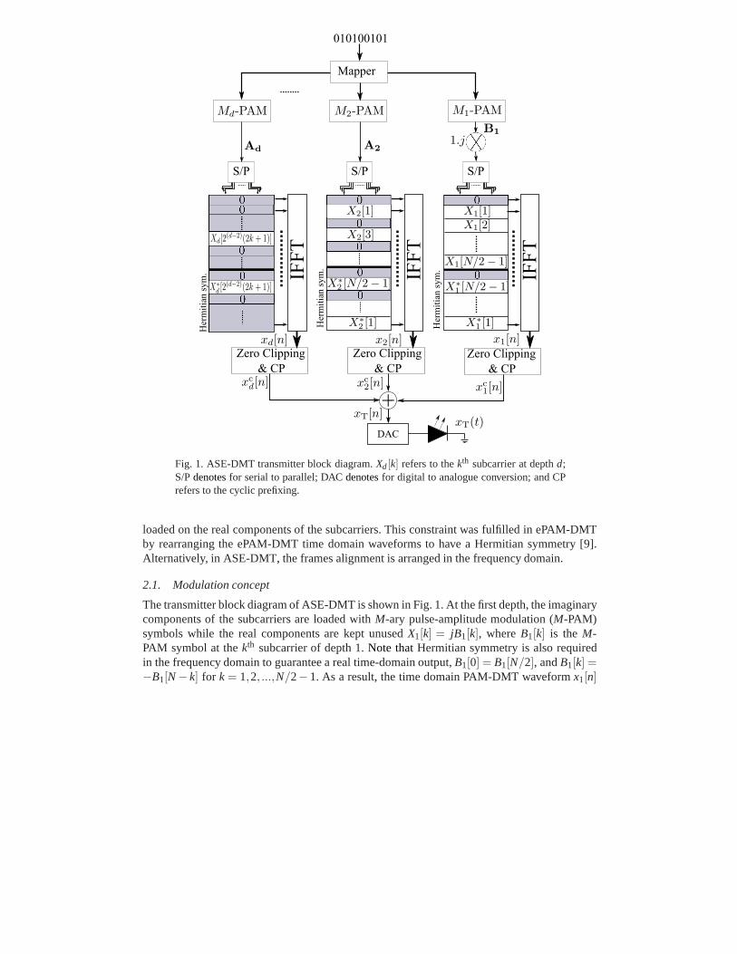
Fig. 1. ASE-DMT transmitter block diagram.Xd[k] refers to thekth subcarrier at depthd;S/Pdenotesfor serial to parallel; DACdenotesfor digital to analogue conversion; and CPrefers to the cyclic prefixing.
loaded on the real components of the subcarriers. This constraint was fulfilled in ePAM-DMTby rearranging the ePAM-DMT time domain waveforms to have a Hermitian symmetry [9].Alternatively, in ASE-DMT, the frames alignment is arranged in the frequency domain.
2.1. Modulation concept
The transmitter block diagram of ASE-DMT is shown in Fig. 1. At the first depth, the imaginarycomponents of the subcarriers are loaded withM-ary pulse-amplitude modulation (M-PAM)symbols while the real components are kept unusedX1[k] = jB1[k], whereB1[k] is the M-PAM symbol at thekth subcarrier of depth 1.Note thatHermitian symmetry is also requiredin the frequency domain to guarantee a real time-domain output,B1[0] = B1[N/2], andB1[k] =−B1[N− k] for k = 1,2, ...,N/2−1. As a result, the time domain PAM-DMT waveformx1[n]
k0 5 10 15
Depth3
-2
0
2
k0 2 6 10 14
-2
0
2
k0 5 10 15
Depth2
-2
0
2
k1 3 5 7 9 111315
0
2
k0 5 10 15Depth1
-2
0
2
k0 5 10 15
-2
0
2
Xd[k]
Xcd[k]
Im[.]
(b)
(d)
(f)(e)
(c)
(a)
Re[.]
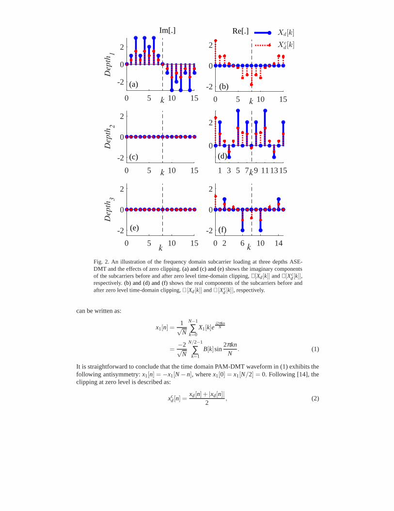
Fig. 2. An illustration of the frequency domain subcarrier loading at three depths ASE-DMT and the effects of zero clipping.(a) and (c) and (e)shows the imaginary componentsof the subcarriers before and after zero level time-domain clipping, ℑ[Xd[k]] andℑ[Xc
d[k]],respectively.(b) and (d) and (f)shows the real components of the subcarriers before andafter zero level time-domain clipping,ℜ[Xd[k]] andℜ[Xc
d [k]], respectively.
can be written as:
x1[n] =1√N
N−1
∑k=0
X1[k]ej2πkn
N
=−2√
N
N/2−1
∑k=1
B[k]sin2πkn
N. (1)
It is straightforward to conclude that the time domain PAM-DMT waveform in (1) exhibits thefollowing antisymmetry:x1[n] = −x1[N−n], wherex1[0] = x1[N/2] = 0. Following [14], theclipping at zero level is described as:
xcd[n] =
xd[n]+ |xd[n]|2
, (2)
and the frequency domain transformation of the clipped waveform, xcd[n], can be shown as:
Xcd[k] =
Xd[k]+FFT{|xd[n]|}2
, (3)
where the subscriptsd denotes the depthd index, andXd[k] = FFT{xd[n]}. The effects of clip-ping on the subcarriers are shown in Fig. 2. Clipping of the negative samples at depth 1 isdistortion-less to the information at the same depthbecauseall of the distortion transforms intothe real part of the subcarriers. As a simple proof, the distortion term|x1[n]| has a Hermitiansymmetry|x1[n]| = |x1[N−n]|, which can also be proved by:
FFT{|x1[n]|} =1√N
N−1
∑n=0
|x1[n]|e−j2πkn
N
=2√N
N/2−1
∑n=1
|x1[n]|cos2πkn
N. (4)
At depth 2, the odd subcarriers are loaded with real valuedM-PAM symbolsX2[k] = A2[k],while all of the other subcarriers are kept unused. The subcarriers at depth 2,X2[k], can bewritten as:
X2[k′] =
{
A2[k′], if k′ = 2k+1
0, Otherwise, (5)
whereA2[k′] is theM-PAM symbol at thek′th subcarrier of depth 2; andk = 0,1, ...,N/4−1.Hermitian symmetry is also required to guarantee thatx2[n] is real,A2[k] = A2[N− k]. As aresult, the time domain waveform at depth 2,x2[n], would have the following symmetry:x2[n] =−x2[n+ N/2]. Therefore, the distortion caused by clipping at zero levelwould only affect thereal domain even subcarriers. This can be shown as:
FFT{|x2[n]|} =1√N
N/2−1
∑n=0
|x2[k]|e−j2πkn
N (1+e− jπk), (6)
which takes values only atXc2[2k], for k = 0,1, ...,N/2−1. Therefore, the distortion is orthog-
onal to the information content at depth 1 and depth 2. Subsequent streams can be generated atdepthd, where the subcarriers will be loaded with real valuedM-PAM symbols:
Xd[k′] =
{
Ad[k′], if k′ = 2d−2(2k+1)
0, Otherwise, (7)
whereAd[k′] is theM-PAM symbol at thek′th subcarrier of depthd; andk = 0,1, ...,N/2d −1.Hermitian symmetry is also required to guarantee thatxd[n] is real,Ad[k] = Ad[N− k]. Using(7), it can be shown that:
xd[n] = −xd[n+N/2d−1] ∀d > 1. (8)
Using (3),Xd[k] can be written as:
Xd[k] =1√N
N/2d−1−1
∑n=0
xd[k]e− j2πkn
N κ(1−e− jπk2D−2 ), (9)
and the zero level clipping distortion effect on the subcarriers in the frequency domain can bewritten as:
FFT{|xd[n]|} =1√N
N/2d−1−1
∑n=0
|xd[k]|e−j2πkn
N κ(1+e− jπk2D−2 ), (10)
whereD is the total number of used depths, andκ can be written as:
κ =D−1
∏d=2
(1+e− jπk2d−2 ). (11)
Using (9) and (10), it can be shown that the zero level clipping is distortion-less to the in-formation content atXc
d[2d−2(2k+ 1)], and that all of the distortion will affect the subcarriersat Xc
d[2d−1k]. Using this technique of selective subcarrier indexes loading at each depth willallow multiple M-PAM modulated waveforms to be superimposed without any inter-stream-interference. The active subcarriers of each superimposeddepth will not be affected by the zerolevel clipping distortion of the current and subsequent depths. However, it will be affected bythe distortion of the zero level clipping of the previous depths. This distortion will be estimatedand cancelled at the receiver, as shownbelow.
After generating the time domain waveforms of all depths, the generated waveforms areclipped and the cyclic prefixes are prefixed. The overall ASE-DMT waveform can be obtainedby superimposing the clipped waveforms of all depths:
xT[n] =D
∑d=1
xcd[n]. (12)
Using (2) and (3), the ASE-DMT subcarriers can be written as:
XT[k] =jB1[k]+ ∑D
d=2Ad[k]+ ∑Dd=1FFT{|Xd[n]|}
2. (13)
The information content of depth 1 can be obtained by considering only the imaginary com-ponents of the subcarriers. This can be given asB̂1[k] = 2ℑ(XT[k])+W[k], whereW[k] is thefrequency domain realization of the additive white Gaussian noise (AWGN) at the receiver [2].The information of depth 1 can then be remodulated at the receiver to obtain ˆx1[n] which canbe subtracted from the ASE-DMT received waveform,xT[n]. This would result in removing theimaginary component ofXT[n] andalso removing the real domain distortion caused by the zerolevel clipping ofthedepth 1 waveform, FFT{|x1[n]|}. Subsequent depths can be demodulatedby selecting the appropriate frequency subcarrier indexesat each depth. The real componentof the subcarriers at 2d−2(2k+ 1) for k = 0,1, ...,N/2d − 1 can then be remodulated to ob-tain the waveform at depthd, x̂d[n], which would be subtracted from the remaining ASE-DMTwaveform.
The same process is repeated until the information at the last depth is demodulated. In thisway the distortion of the previous depths is estimated and cancelled from the higher depths inthis successive receiver process.
2.2. Spectral efficiency
The spectral efficiency of the first depth of ASE-DMT is equivalent to the spectral efficiency ofPAM-DMT, which is also similar to the spectral efficiency of DCO-OFDM. This can be writtenas:
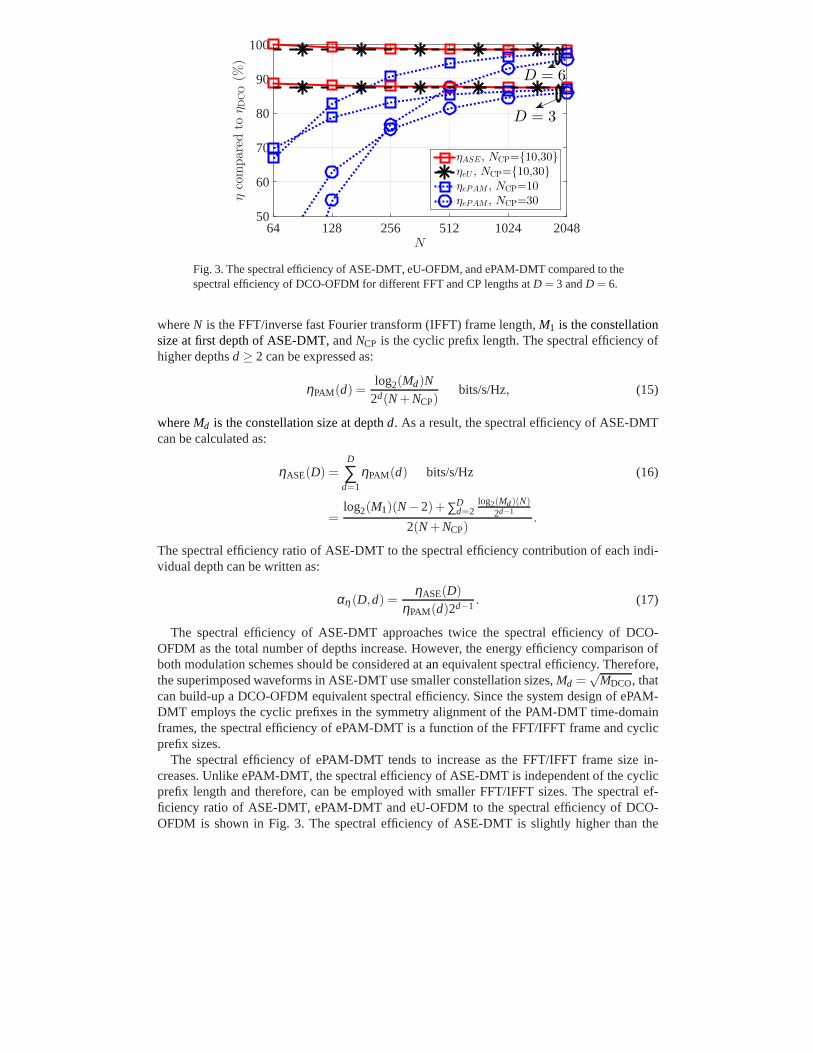
Fig. 3. The spectral efficiency of ASE-DMT, eU-OFDM, and ePAM-DMT compared to thespectral efficiency of DCO-OFDM for different FFT and CP lengths atD = 3 andD = 6.
whereN is the FFT/inverse fast Fourier transform (IFFT) frame length, M1 is the constellationsize at first depth of ASE-DMT,andNCP is the cyclic prefix length. The spectral efficiency ofhigher depthsd ≥ 2 can be expressed as:
ηPAM(d) =log2(Md)N
2d(N+NCP)bits/s/Hz, (15)
whereMd is the constellation size at depthd. As a result, the spectral efficiency of ASE-DMTcan be calculated as:
ηASE(D) =D
∑d=1
ηPAM(d) bits/s/Hz (16)
=log2(M1)(N−2)+ ∑D
d=2log2(Md)(N)
2d−1
2(N+NCP).
The spectral efficiency ratio of ASE-DMT to the spectral efficiency contribution of each indi-vidual depth can be written as:
αη(D,d) =ηASE(D)
ηPAM(d)2d−1 . (17)
The spectral efficiency of ASE-DMT approaches twice the spectral efficiency of DCO-OFDM as the total number of depths increase. However, the energy efficiency comparison ofboth modulation schemes should be considered atanequivalent spectral efficiency. Therefore,the superimposed waveforms in ASE-DMT use smaller constellation sizes,Md =
√MDCO, that
can build-up a DCO-OFDM equivalent spectral efficiency. Since the system design of ePAM-DMT employs the cyclic prefixes in the symmetry alignment of the PAM-DMT time-domainframes, the spectral efficiency of ePAM-DMT is a function of the FFT/IFFT frame and cyclicprefix sizes.
The spectral efficiency of ePAM-DMT tends to increase as the FFT/IFFT frame size in-creases. Unlike ePAM-DMT, the spectral efficiency of ASE-DMT is independent of the cyclicprefix length and therefore, can be employed with smaller FFT/IFFT sizes. The spectral ef-ficiency ratio of ASE-DMT, ePAM-DMT and eU-OFDM to the spectral efficiency of DCO-OFDM is shown in Fig. 3. The spectral efficiency of ASE-DMT is slightly higher than the
spectral efficiency of eU-OFDM at small FFT/IFFT sizes. It isshown that whenD = 6 andN = 64, the spectral efficiency of ASE-DMT exactly matches the spectral efficiency of DCO-OFDM.
2.3. Power efficiency
The real bipolar OFDM time-domain waveform can be approximated with a Normal distribu-tion, x(t) ∼ N (0,σ2
x ) when N ≥ 64, whereσx is the standard deviation ofx(t) [2]. It wasshown in [14] that PAM-DMT follows a truncated normal distribution.The stream at depthDis scaled by a parameter 1/γd to facilitate the optimization of the allocated power at that stream.The ASE-DMT time-domain waveform at depthd follows a truncated normal distribution witha mean E[xd(t)] = φ(0)σx/(γd
√2d−1), where1/γd is the scaling factor at depthd, E[·] is a sta-
tistical expectation, andφ(x) is the probability density function (PDF) of the standard normaldistribution. As a result, the average electrical and optical power of ASE-DMT is equivalent tothe electrical and optical power of eU-OFDM which can be written as [15]:
PavgEle
(D,γ) = E[
x2T(t)
]
= E
(
D
∑d=1
xd(t)
)2
= σ2s
D
∑d=1
γ−2d
2d +2φ2(0)D
∑d1=1
D
∑d2=1d1 6=d2
(γd1γd2)−1
√2d1+d2
, (18)
PavgOpt(D,γ) =
D
∑d=1
E[sd(t)] = φ(0)σs
D
∑d=1
γ−1d√2d−1
, (19)
wherexT(t) is the time domain ASE-DMT waveform; xd(t) is the time domain PAM-DMT atdepthd; andγ = {γ−1
d ;d = 1,2, . . . ,D} is the set of scaling factors applied to each correspond-ing stream.The ratio of the average electrical power of ASE-DMT waveform to the averageelectrical power of a PAM-DMT stream,Pavg
Ele,d(γd) = σ2x /(2γ2
d), is given by:
αPEle(D,γ) =
PavgEle
(D,γ)
PavgEle,d(γd)
. (20)
3. TheoreticalBER analysis
The ASE-DMT received signal is given by:
y = Hx +w, (21)
wherex andy are the transmitted and received ASE-DMT waveforms;w = {wi ; i = 0,1, ...,N−1} is the AWGN samples,wi ∼ N (0,No), whereNo is the double-sided power spectral density(PSD) of the noise at the receiver; andH is aN×N circulant convolution channel matrix withthe first column representing the channel impulse responseh = [h0,h1, ...,hL,0, ...,0]T, whereL is the number of channel taps. The channel matrixH can be diagonalized as:
H = F∗ΛΛΛF, (22)
whereF is anN×N Discrete Fourier transform (DFT) matrix, andΛΛΛ is anN×N diagonalmatrix with the eigenvalues of the channelΛΛΛ = [Λ0,Λ1, ...,ΛN]T.
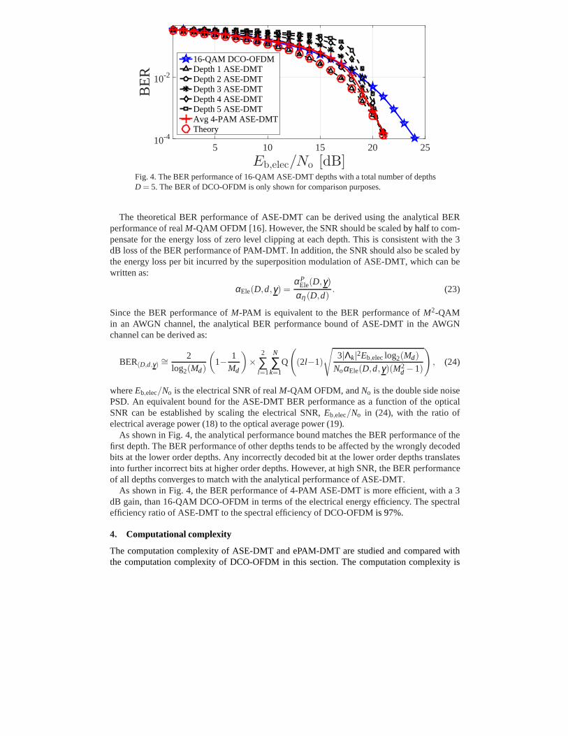
Fig. 4. The BER performance of 16-QAM ASE-DMT depths with a total number of depthsD = 5. The BER of DCO-OFDM is only shown for comparison purposes.
The theoretical BER performance of ASE-DMT can be derived using the analytical BERperformance of realM-QAM OFDM [16]. However, the SNR should be scaledby half to com-pensate for the energy loss of zero level clipping at each depth. This is consistent with the 3dB loss of the BER performance of PAM-DMT. In addition, the SNR should also be scaled bythe energy loss per bit incurred by the superposition modulation of ASE-DMT, which can bewritten as:
αEle(D,d,γ) =αP
Ele(D,γ)
αη (D,d). (23)
Since the BER performance ofM-PAM is equivalent to the BER performance ofM2-QAMin an AWGN channel, the analytical BER performance bound of ASE-DMT in the AWGNchannel can be derived as:
BER(D,d,γ)∼= 2
log2(Md)
(
1− 1Md
)
×2
∑l=1
N
∑k=1
Q
(
(2l−1)
√
3|Λk|2Eb,eleclog2(Md)
NoαEle(D,d,γ)(M2d −1)
)
, (24)
whereEb,elec/No is the electrical SNR of realM-QAM OFDM, andNo is the double side noisePSD. An equivalent bound for the ASE-DMT BER performance as afunction of the opticalSNR can be established by scaling the electrical SNR,Eb,elec/No in (24), with the ratio ofelectrical average power (18) to the optical average power (19).
As shown in Fig. 4, the analytical performance bound matches the BER performance of thefirst depth. The BER performance of other depths tends to be affected by the wrongly decodedbits at the lower order depths. Any incorrectly decoded bit at the lower order depths translatesinto further incorrect bits at higher order depths. However, at high SNR, the BER performanceof all depths converges to match with the analytical performance of ASE-DMT.
As shown in Fig. 4, the BER performance of 4-PAM ASE-DMT is more efficient, with a 3dB gain, than 16-QAM DCO-OFDM in terms of the electrical energy efficiency. The spectralefficiency ratio of ASE-DMT to the spectral efficiency of DCO-OFDM is 97%.
4. Computational complexity
The computation complexity of ASE-DMT and ePAM-DMT are studied and compared withthe computation complexity of DCO-OFDM in this section. Thecomputation complexity is
dominated by the number of multiplications in FFT/IFFT operations. Therefore, the computa-tion complexity in this paper is defined as the number of complex multiplications required toperform a FFT/IFFT operation.
4.1. Computation complexity of DCO-OFDM
At the transmitter side, DCO-OFDM requiresN-point complex multiplications which result ina computation complexity ofO(N log2(N)). The FFT operation at the receiver side of DCO-OFDM is performed on real-valued frames. TwoN-point FFT operations on two real-valuedsignals can be realized using oneN-point FFT on one complex-valued signal [17]. Therefore,the computation complexity at the receiver of DCO-OFDM isO(N/2log2(N)). The computa-tion complexity per bit of DCO-OFDM can be written as:
CDCO =2O(3N/2log2(N))
log2(MDCO)(N−2), (25)
whereMDCO is the constellation size of DCO-OFDM.
4.2. Computation complexity of ASE-DMT
At the transmitter side of PAM-DMT, an IFFT operation is applied on imaginary-valuedframes. At the receiver side, a single FFT operation is applied on real-valued frames. There-fore, the computation complexity of PAM-DMT for each of the transmitter and receiver isO(N/2log2(N)).
The first depth of ASE-DMT has a computation complexity similar to the computation com-plexity of a PAM-DMT transmitter. Higher depths of ASE-DMT are sparse as they have a lownumber of active subcarriers. The number of active subcarriers at depthd is: N/2d−1, ∀d ≤ 2.Therefore, the IFFT operation at higher order depthsd ≤ 2, can be optimized to avoid the cal-culations performed on zeros. Given that the subcarriers inthese depths are real-valued, thecomputation complexity at the transmitter of depthd is O(N/2d log2(N)). Therefore, the com-putation complexity of ASE-DMT transmitter is given as:
CTxASE = O(N/2log2(N))+
D
∑d=2
O(N/2d log2(N))
≈ O(N log2(N)), (26)
whereD is the total number of depths.The first demodulation process at the receiver of ASE-DMT is applied on real-valued frames,
therefore, the computation complexity associated with this process is equivalent to the com-putation complexity of a DCO-OFDM receiver. All the other demodulation process are alsoapplied on real-valued frames. However, the frames at higher order depths are sparse in thefrequency domain. A specific set of subcarriers is only required at the output of each demodu-lation process. Therefore, the FFT operation at higher order depths,d ≤ 2, is only evaluated atsubcarriers given by (7). Algorithms such as Sparse FFT [18]can also be applied for depthdwith a computational complexity ofO(N/2d log2(N)). The demodulated streams for all depths,except the last one, are required to be remodulated at the receiver. The associated complexity ofremodulating the first depth is:O(N/2log2(N)), and the associated complexity of remodulatingother depths is∑D
d=2O(N/2d log2(N)). Therefore, the computation complexity of a ASE-DMTreceiver is given as:
CRxASE = O(N/2log2(N))+
D
∑d=2
O(N/2d log2(N))+D−1
∑d=2
O(N/2d log2(N))
≈ O(2N log2(N)). (27)
NCP/N (%)
24
623
D
45678
2
2.1
2.2
2.3
1.8
1.9RelativeComplexity
CASE/CDCO
CePAM/CDCO
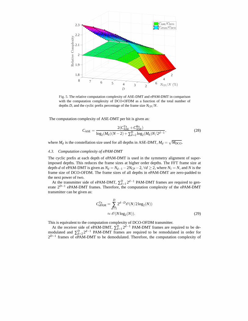
Fig. 5.The relative computation complexity of ASE-DMT and ePAM-DMT in comparisonwith the computation complexity of DCO-OFDM as a function ofthe total number ofdepthsD, and the cyclic prefix percentage of the frame sizeNCP/N.
The computation complexity of ASE-DMT per bit is given as:
CASE =2(CTx
ASE+CRxASE)
log2(Md)(N−2)+ ∑Dd=2 log2(Md)N/2d−1
, (28)
whereMd is the constellation size used for all depths in ASE-DMT,Md =√
MDCO.
4.3. Computation complexity of ePAM-DMT
The cyclic prefix at each depth of ePAM-DMT is used in the symmetry alignment of super-imposed depths. This reduces the frame sizes at higher orderdepths. The FFT frame size atdepth-d of ePAM-DMT is given asNd = Nd−1−2NCP−2,∀d ≥ 2, whereN1 = N, andN is theframe size of DCO-OFDM. The frame sizes of all depths in ePAM-DMT are zero-padded tothe next power of two.
At the transmitter side of ePAM-DMT,∑Dd=12d−1 PAM-DMT frames are required to gen-
erate 2D−1 ePAM-DMT frames. Therefore, the computation complexity ofthe ePAM-DMTtransmitter can be given as:
CTxePAM =
D
∑d=1
2d−DO(N/2log2(N))
≈ O(N log2(N)). (29)
This is equivalent to the computation complexity of DCO-OFDM transmitter.At the receiver side of ePAM-DMT,∑D
d=12d−1 PAM-DMT frames are required to be de-modulated and∑D
d=22d−1 PAM-DMT frames are required to be remodulated in order for2D−1 frames of ePAM-DMT to be demodulated. Therefore, the computation complexity of
the ePAM-DMT receiver can be given as:
CRxePAM =
O(N/2log2(N))+2∑Dd=22d−1O(N/2log2(N))
2D−1
≈ O(2N log2(N)), (30)
which is equivalent to twice the computation complexity of DCO-OFDM transmitter. Thereforethe computation complexity of ePAM-DMT per bit is given as:
CePAM =2(CTx
ePAM+CRxePAM)
log2(M)(N−2)+ ∑Dd=2 log2(M)Nd/2d−1
, (31)
whereNd is the frame size at depth-d andM is the constellation size used for all depths inePAM-DMT, M =
√MDCO.
4.4. Computation complexity comparison
The ratio of the computation complexities per bit of ASE-DMTto DCO-OFDM,CASE/CDCO,and the the ratio of the computation complexities per bit of ePAM-DMT to DCO-OFDM,CePAM/CDCO. are presented in Fig. 5 as a function of the total number of used depthsD andthe cyclic prefix percentage of the overall frame sizeNCP/N. The relative complexity of ASE-DMT is independent of the cyclic prefix and it increases as thetotal number of depths increases.However, it converges to twice the complexity of DCO-OFDM.
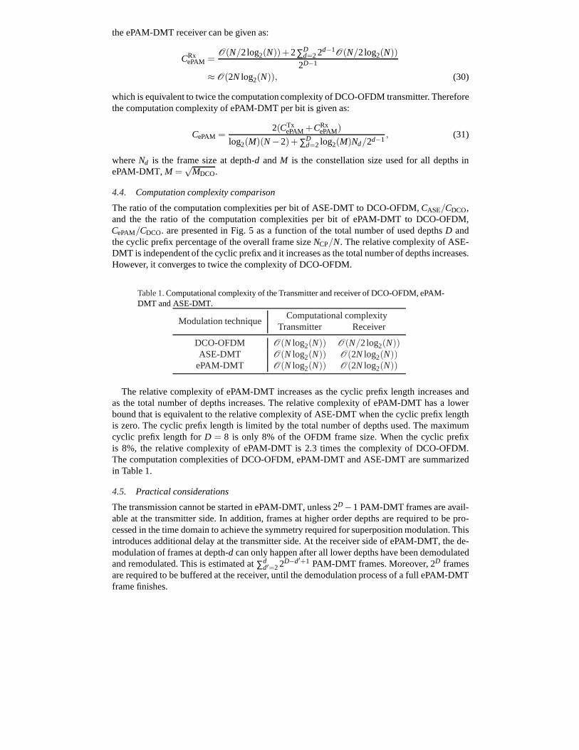
Table 1.Computational complexity of the Transmitter and receiver of DCO-OFDM, ePAM-DMT and ASE-DMT.
The relative complexity of ePAM-DMT increases as the cyclicprefix length increases andas the total number of depths increases. The relative complexity of ePAM-DMT has a lowerbound that is equivalent to the relative complexity of ASE-DMT when the cyclic prefix lengthis zero. The cyclic prefix length is limited by the total number of depths used. The maximumcyclic prefix length forD = 8 is only 8% of the OFDM frame size. When the cyclic prefixis 8%, the relative complexity of ePAM-DMT is 2.3 times the complexity of DCO-OFDM.The computation complexities of DCO-OFDM, ePAM-DMT and ASE-DMT are summarizedin Table 1.
4.5. Practical considerations
The transmission cannot be started in ePAM-DMT, unless 2D−1 PAM-DMT frames are avail-able at the transmitter side. In addition, frames at higher order depths are required to be pro-cessed in the time domain to achieve the symmetry required for superposition modulation. Thisintroduces additional delay at the transmitter side. At thereceiver side of ePAM-DMT, the de-modulation of frames at depth-d can only happen after all lower depths have been demodulatedand remodulated. This is estimated at∑d
d′=22D−d′+1 PAM-DMT frames. Moreover, 2D framesare required to be buffered at the receiver, until the demodulation process of a full ePAM-DMTframe finishes.
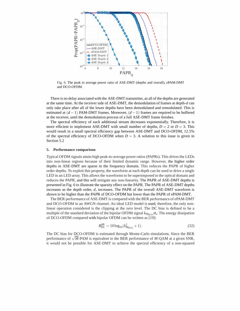
Fig. 6. The peak to average power ratio of ASE-DMT (depths and overall), ePAM-DMTand DCO-OFDM.
There is no delay associated with the ASE-DMT transmitter, as all of the depths are generatedat the same time. At the receiver side of ASE-DMT, the demodulation of frames at depth-d canonly take place after all of the lower depths have been demodulated and remodulated. This isestimated at(d−1) PAM-DMT frames. Moreover,(d−1) frames are required to be bufferedat the receiver, until the demodulation process of a full ASE-DMT frame finishes.
The spectral efficiency of each additional stream decreasesexponentially. Therefore, it ismore efficient to implement ASE-DMT with small number of depths,D = 2 or D = 3. Thiswould result in a small spectral efficiency gap between ASE-DMT and DCO-OFDM, 12.5%of the spectral efficiency of DCO-OFDM whenD = 3. A solution to this issue is given inSection 5.2
5. Performance comparison
Typical OFDM signals attain high peak-to-average power ratios (PAPRs). This drives the LEDsinto non-linear regions because of their limited dynamic range. However,the higher orderdepths in ASE-DMT are sparse in the frequency domain.This reduces the PAPR of higherorder depths. To exploit this property, the waveform at eachdepth can be used to drive a singleLED in an LED array. This allows the waveforms to be superimposed in the optical domain andreduces the PAPR,and this willmitigate any non-linearity.The PAPR of ASE-DMT depths ispresented in Fig. 6 to illustrate the sparsity effect on the PAPR. The PAPR of ASE-DMT depthsincreases as the depth order,d, increases. The PAPR of the overall ASE-DMT waveform isshown to be higher than the PAPR of DCO-OFDM but lower than thePAPR of ePAM-DMT.
The BER performance of ASE-DMT is compared with the BER performance of ePAM-DMTand DCO-OFDM in an AWGN channel. An ideal LED model isused, therefore, the only non-linear operation considered is the clipping at the zero level. The DC bias is defined to be amultiple of the standard deviation of the bipolar OFDM signal kMDCOσs. The energy dissipationof DCO-OFDM comparedwith bipolar OFDM can be written as [19]:
BdBDC = 10log10(k
2MDCO
+1). (32)
The DC bias for DCO-OFDM is estimated through Monte-Carlo simulations. Since the BERperformance of
√M-PAM is equivalent to the BER performance ofM-QAM at a given SNR,
it would not be possible for ASE-DMT to achieve the spectral efficiency of a non-squared
(a) Eb,elec/No [dB]10 15 20 25 30 35 40
BE
R
10-4
10-3
10-2
10-1
M-QAM DCO√M 1×3-ePAM√M 1×3-ASE
Theory
M = 1024
M = 64
M = 4
(b) Eb,opt/No [dB]5 10 15 20 25 30 35
BE
R
10-4
10-3
10-2
10-1
M-QAM DCO√M 1×3-ePAM√M 1×3-ASE
Theory
M = 64
M = 1024
M = 4
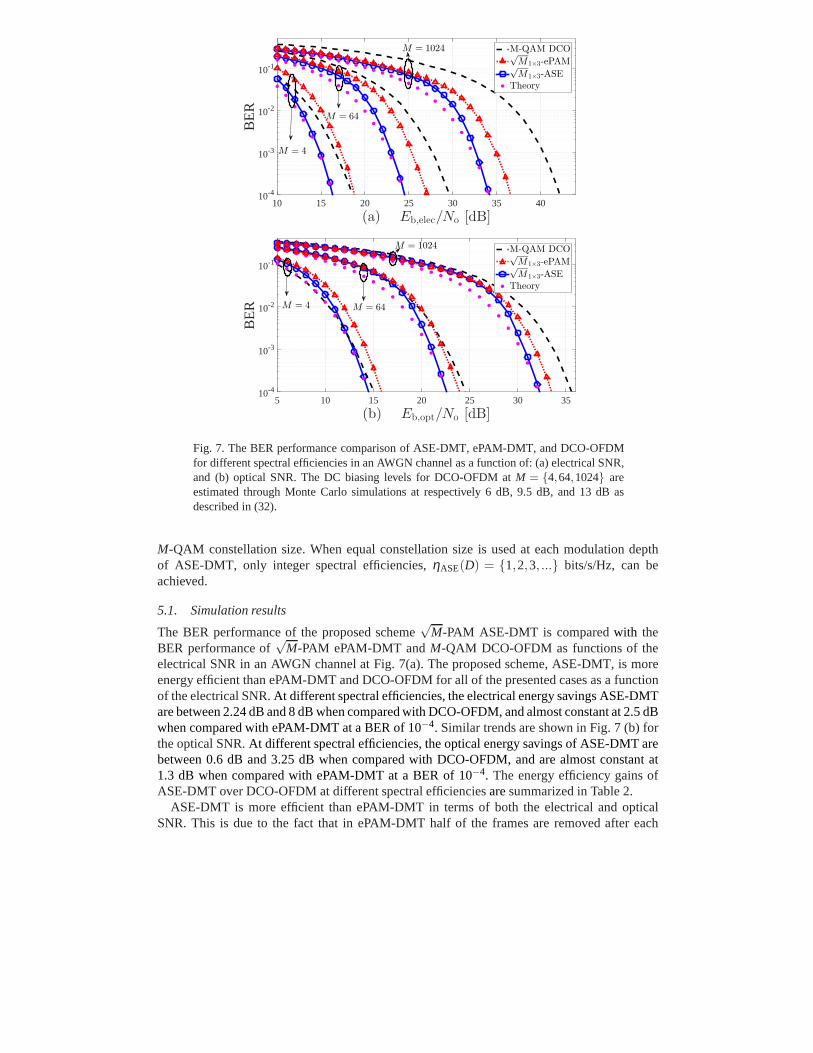
Fig. 7. The BER performance comparison of ASE-DMT, ePAM-DMT, and DCO-OFDMfor different spectral efficiencies in an AWGN channel as a function of: (a) electrical SNR,and (b) optical SNR. The DC biasing levels for DCO-OFDM atM = {4,64,1024} areestimated through Monte Carlo simulations at respectively6 dB, 9.5 dB, and 13 dB asdescribed in (32).
M-QAM constellation size. When equal constellation size is used at each modulation depthof ASE-DMT, only integer spectral efficiencies,ηASE(D) = {1,2,3, ...} bits/s/Hz, can beachieved.
5.1. Simulation results
The BER performance of the proposed scheme√
M-PAM ASE-DMT is comparedwith theBER performance of
√M-PAM ePAM-DMT andM-QAM DCO-OFDM as functions of the
electrical SNR in an AWGN channel at Fig. 7(a). The proposed scheme, ASE-DMT, is moreenergy efficient than ePAM-DMT and DCO-OFDM for all of the presented cases as a functionof the electrical SNR.At different spectral efficiencies, the electrical energy savings ASE-DMTare between 2.24 dB and 8 dB when compared with DCO-OFDM, and almost constant at 2.5 dBwhen compared with ePAM-DMT at a BER of 10−4. Similar trends are shown in Fig. 7 (b) forthe optical SNR.At different spectral efficiencies, the optical energy savings of ASE-DMT arebetween 0.6 dB and 3.25 dB when compared with DCO-OFDM, and are almost constant at1.3 dB when compared with ePAM-DMT at a BER of 10−4. The energy efficiency gains ofASE-DMT over DCO-OFDM at different spectral efficienciesaresummarized in Table 2.
ASE-DMT is more efficient than ePAM-DMT in terms of both the electrical and opticalSNR. This is due to the fact that in ePAM-DMT half of the framesare removed after each
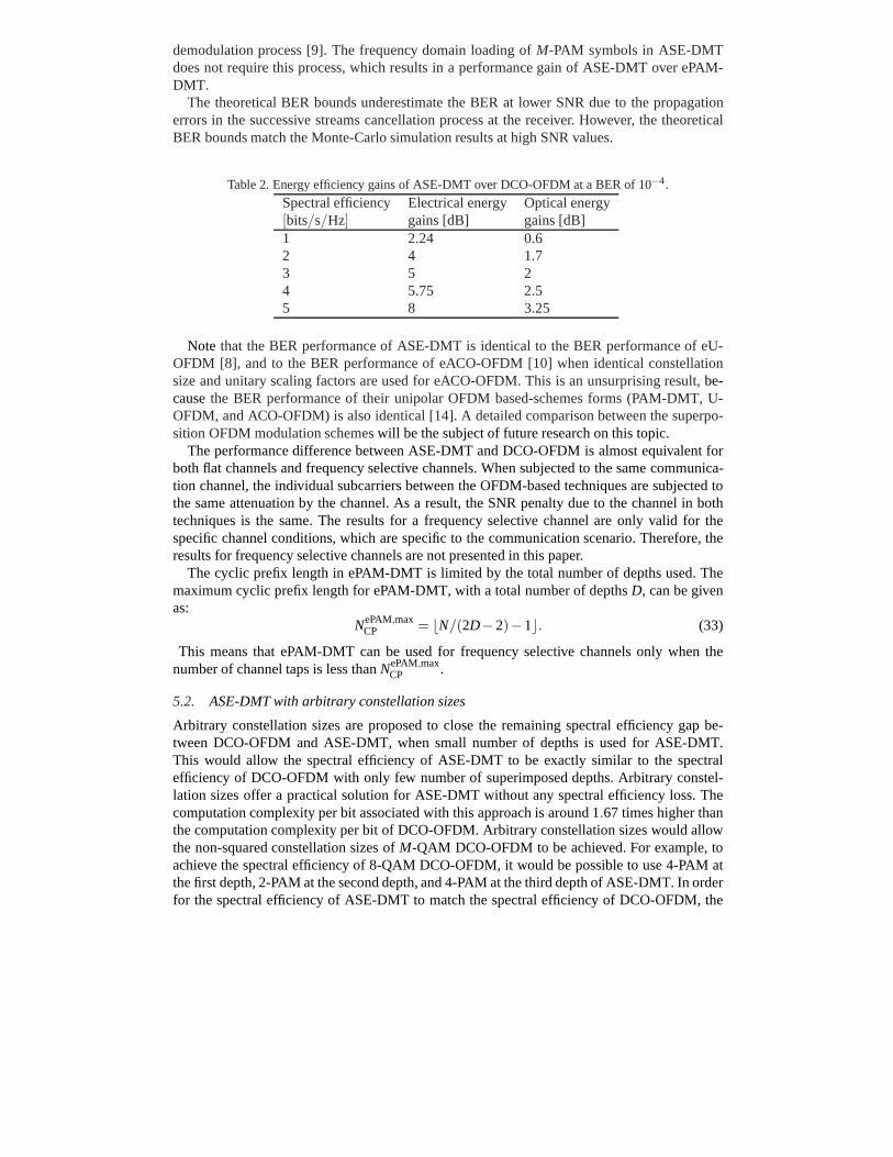
demodulation process [9]. The frequency domain loading ofM-PAM symbols in ASE-DMTdoes not require this process, which results in a performance gain of ASE-DMT over ePAM-DMT.
The theoretical BER bounds underestimate the BER at lower SNR due to the propagationerrors in the successive streams cancellation process at the receiver. However, the theoreticalBER bounds match the Monte-Carlo simulation results at highSNR values.
Table 2. Energy efficiency gains of ASE-DMT over DCO-OFDM at aBER of 10−4.
Note that the BER performance of ASE-DMT is identical to the BER performance of eU-OFDM [8], and to the BER performance of eACO-OFDM [10] when identical constellationsize and unitary scaling factors are used for eACO-OFDM. This is an unsurprising result,be-causethe BER performance of their unipolar OFDM based-schemes forms (PAM-DMT, U-OFDM, and ACO-OFDM) is also identical [14]. A detailed comparison between the superpo-sition OFDM modulation schemeswill be the subject of future research on this topic.
The performance difference between ASE-DMT and DCO-OFDM isalmost equivalent forboth flat channels and frequency selective channels. When subjected to the same communica-tion channel, the individual subcarriers between the OFDM-based techniques are subjected tothe same attenuation by the channel. As a result, the SNR penalty due to the channel in bothtechniques is the same. The results for a frequency selective channel are only valid for thespecific channel conditions, which are specific to the communication scenario. Therefore, theresults for frequency selective channels are not presentedin this paper.
The cyclic prefix length in ePAM-DMT is limited by the total number of depths used. Themaximum cyclic prefix length for ePAM-DMT, with a total number of depthsD, can be givenas:
NePAM,maxCP = ⌊N/(2D−2)−1⌋. (33)
This means that ePAM-DMT can be used for frequency selectivechannels only when thenumber of channel taps is less thanNePAM,max
CP .
5.2. ASE-DMT with arbitrary constellation sizes
Arbitrary constellation sizes are proposed to close the remaining spectral efficiency gap be-tween DCO-OFDM and ASE-DMT, when small number of depths is used for ASE-DMT.This would allow the spectral efficiency of ASE-DMT to be exactly similar to the spectralefficiency of DCO-OFDM with only few number of superimposed depths. Arbitrary constel-lation sizes offer a practical solution for ASE-DMT withoutany spectral efficiency loss. Thecomputation complexity per bit associated with this approach is around 1.67 times higher thanthe computation complexity per bit of DCO-OFDM. Arbitrary constellation sizes would allowthe non-squared constellation sizes ofM-QAM DCO-OFDM to be achieved. For example, toachieve the spectral efficiency of 8-QAM DCO-OFDM, it would be possible to use 4-PAM atthe first depth, 2-PAM at the second depth, and 4-PAM at the third depth of ASE-DMT. In orderfor the spectral efficiency of ASE-DMT to match the spectral efficiency of DCO-OFDM, the
(a) Eb,ele/No [dB]10 15 20 25 30 35 40
BE
R
10-4
10-3
10-2
10-1
DCO-OFDMePAM-DMTASE-DMTTheory
η = 1.5
η = 3
η = 4.5
(b) Eb,opt/No [dB]5 10 15 20 25 30 35
BE
R
10-4
10-3
10-2
10-1
DCO-OFDMePAM-DMTASE-DMTTheory
η = 1.5 η = 3
η = 4.5
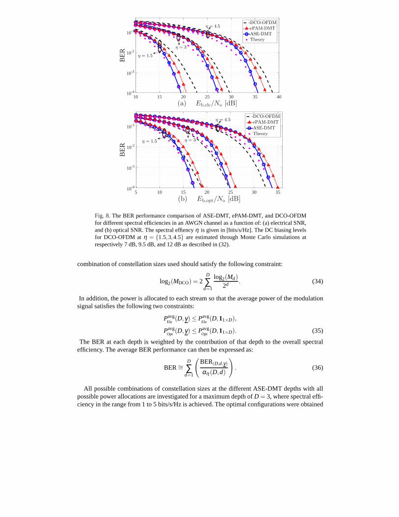
Fig. 8.The BER performance comparison of ASE-DMT, ePAM-DMT, and DCO-OFDMfor different spectral efficiencies in an AWGN channel as a function of: (a) electrical SNR,and (b) optical SNR. The spectral effiencyη is given in [bits/s/Hz]. The DC biasing levelsfor DCO-OFDM atη = {1.5,3,4.5} are estimated through Monte Carlo simulations atrespectively 7 dB, 9.5 dB, and 12 dB as described in (32).
combination of constellation sizes used should satisfy thefollowing constraint:
log2(MDCO) = 2D
∑d=1
log2(Md)
2d . (34)
In addition, the power is allocated to each stream so that theaverage power of the modulationsignal satisfies the following two constraints:
PavgEle
(D,γ) ≤ PavgEle
(D,11×D),
PavgOpt
(D,γ) ≤ PavgOpt
(D,11×D). (35)
The BER at each depth is weighted by the contribution of that depth to the overall spectralefficiency. The average BER performance can then be expressed as:
BER∼=D
∑d=1
(
BER(D,d,γ)
αη (D,d)
)
. (36)
All possible combinations of constellation sizes at the different ASE-DMT depths with allpossible power allocations are investigated for a maximum depth ofD = 3, where spectral effi-ciency in the range from 1 to 5 bits/s/Hz is achieved. The optimal configurations were obtained
using Monte Carlo simulation comparisons of all the possible sets. The optimal configurationsare presented in Table 3.
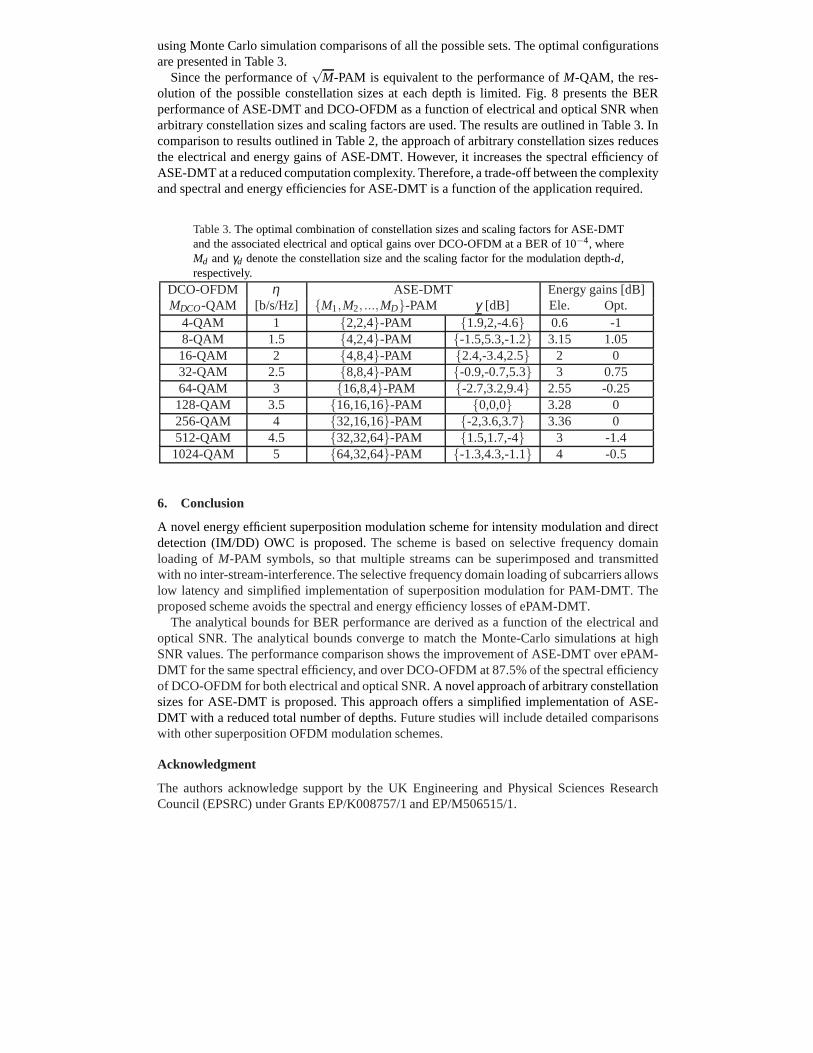
Since the performance of√
M-PAM is equivalent to the performance ofM-QAM, the res-olution of the possible constellation sizes at each depth islimited. Fig. 8 presents the BERperformance of ASE-DMT and DCO-OFDM as a function of electrical and optical SNR whenarbitrary constellation sizes and scaling factors are used. The results are outlined in Table 3. Incomparison to results outlined in Table 2, the approach of arbitrary constellation sizes reducesthe electrical and energy gains of ASE-DMT. However, it increases the spectral efficiency ofASE-DMT at a reduced computation complexity. Therefore, a trade-off between the complexityand spectral and energy efficiencies for ASE-DMT is a function of the application required.
Table 3.The optimal combination of constellation sizes and scalingfactors for ASE-DMTand the associated electrical and optical gains over DCO-OFDM at a BER of 10−4, whereMd andγd denote the constellation size and the scaling factor for themodulation depth-d,respectively.
DCO-OFDM η ASE-DMT Energy gains [dB]MDCO-QAM [b/s/Hz] {M1,M2, ...,MD}-PAM γ [dB] Ele. Opt.
A novel energy efficient superposition modulation scheme for intensity modulation and directdetection (IM/DD) OWC is proposed.The scheme is based on selective frequency domainloading of M-PAM symbols, so that multiple streams can be superimposed and transmittedwith no inter-stream-interference. The selective frequency domain loading of subcarriers allowslow latency and simplified implementation of superpositionmodulation for PAM-DMT. Theproposed scheme avoids the spectral and energy efficiency losses of ePAM-DMT.
The analytical bounds for BER performance are derived as a function of the electrical andoptical SNR. The analytical bounds converge to match the Monte-Carlo simulations at highSNR values. The performance comparison shows the improvement of ASE-DMT over ePAM-DMT for the same spectral efficiency, and over DCO-OFDM at 87.5% of the spectral efficiencyof DCO-OFDM for both electrical and optical SNR.A novel approach of arbitrary constellationsizes for ASE-DMT is proposed. This approach offers a simplified implementation of ASE-DMT with a reduced total number of depths.Future studies will include detailed comparisonswith other superposition OFDM modulation schemes.
Acknowledgment
The authors acknowledge support by the UK Engineering and Physical Sciences ResearchCouncil (EPSRC) under Grants EP/K008757/1 and EP/M506515/1.