21 Half-overlap Subchannel Filtered MultiTone Modulation and Its Implementation Pavel Silhavy and Ondrej Krajsa Department of Telecommunications, Faculty of Electrical Engineering and Communication, Brno University of Technology, Czech Republic 1. Introduction Multitone modulations are today frequently used modulation techniques that enable optimum utilization of the frequency band provided on non-ideal transmission carrier channel (Bingham, 2000). These modulations are used with especially in data transmission systems in access networks of telephone exchanges in ADSL (asymmetric Digital Subscriber Lines) and VDSL (Very high-speed Digital Subscriber Lines) transmission technologies, in systems enabling transmission over power lines - PLC (Power Line Communication), in systems for digital audio broadcasting (DAB) and digital video broadcasting (DVB) [10]. And, last but not least, they are also used in WLAN (Wireless Local Area Network) networks according to IEEE 802.11a, IEEE 802.11g, as well as in the new WiMAX technology according to IEEE 802.16. This modulation technique makes use of the fact that when the transmission band is divided into a sufficient number of parallel subchannels, it is possible to regard the transmission function on these subchannels as constant. The more subchannels are used, the more the transmission function approximates ideal characteristics (Bingham, 2000). It subsequently makes equalization in the receiver easier. However, increasing the number of subchannels also increases the delay and complication of the whole system. The dataflow carried by individual subchannels need not be the same and the number of bytes carried by one symbol in every subchannel is set such that it maintains a constant error rate with flat power spectral density across the frequency band used. The mechanism of allocating bits to the carriers is referred to as bit loading algorithm. The resulting bit-load to the carriers thus corresponds to an optimum distribution of carried information in the provided band at a minimum necessary transmitting power. In all the above mentioned systems the known and well described modulation DMT (Discrete MultiTone) (Bingham, 2000) or OFDM (Orthogonal Frequency Division Multiplexing) is used. As can be seen, the above technologies use a wide spectrum of transmission media, from metallic twisted pair in systems ADSL and VDSL, through radio channel in WLAN and WiMAX to power lines in PLC systems. Using multitone modulation, in this case DMT and OFDM modulations, with adaptive bit loading across the frequency band efficient data transmission is enabled on higher frequencies than for which the transmission medium was primarily designed (xDSL, PLC) and it is impossible therefore to warrant here its transfer characteristics. In terrestrial www.intechopen.com
Transcript
21
Half-overlap Subchannel Filtered MultiTone Modulation and Its Implementation
Pavel Silhavy and Ondrej Krajsa Department of Telecommunications, Faculty of Electrical Engineering and
Communication, Brno University of Technology, Czech Republic
1. Introduction
Multitone modulations are today frequently used modulation techniques that enable
optimum utilization of the frequency band provided on non-ideal transmission carrier
channel (Bingham, 2000). These modulations are used with especially in data transmission
systems in access networks of telephone exchanges in ADSL (asymmetric Digital Subscriber
Lines) and VDSL (Very high-speed Digital Subscriber Lines) transmission technologies, in
systems enabling transmission over power lines - PLC (Power Line Communication), in
systems for digital audio broadcasting (DAB) and digital video broadcasting (DVB) [10].
And, last but not least, they are also used in WLAN (Wireless Local Area Network)
networks according to IEEE 802.11a, IEEE 802.11g, as well as in the new WiMAX technology
according to IEEE 802.16. This modulation technique makes use of the fact that when the
transmission band is divided into a sufficient number of parallel subchannels, it is possible
to regard the transmission function on these subchannels as constant. The more subchannels
are used, the more the transmission function approximates ideal characteristics (Bingham,
2000). It subsequently makes equalization in the receiver easier. However, increasing the
number of subchannels also increases the delay and complication of the whole system. The
dataflow carried by individual subchannels need not be the same and the number of bytes
carried by one symbol in every subchannel is set such that it maintains a constant error rate
with flat power spectral density across the frequency band used. The mechanism of
allocating bits to the carriers is referred to as bit loading algorithm. The resulting bit-load to
the carriers thus corresponds to an optimum distribution of carried information in the
provided band at a minimum necessary transmitting power.
In all the above mentioned systems the known and well described modulation DMT
(Discrete MultiTone) (Bingham, 2000) or OFDM (Orthogonal Frequency Division
Multiplexing) is used. As can be seen, the above technologies use a wide spectrum of
transmission media, from metallic twisted pair in systems ADSL and VDSL, through radio
channel in WLAN and WiMAX to power lines in PLC systems.
Using multitone modulation, in this case DMT and OFDM modulations, with adaptive bit
loading across the frequency band efficient data transmission is enabled on higher
frequencies than for which the transmission medium was primarily designed (xDSL, PLC)
and it is impossible therefore to warrant here its transfer characteristics. In terrestrial
www.intechopen.com
Discrete Time Systems
364
transmission the relatively long symbol duration allows effective suppression of the
influence of multi-path signal propagation (DAB, DVB, WiMAX, WLAN).
Unfortunately, DMT and OFDM modulation ability will fail to enable quite an effective
utilization of transmission channels with specially formed spectral characteristic with sharp
transients, which is a consequence of individual subchannel frequency characteristic in the
form of sinc function. It is also the reason for the transmission rate loss on channels with the
occurrence of narrow-band noise disturbance, both metallic and terrestrial. Moreover, multi-
path signal propagation suppression on terrestrial channels is achieved only when the delay
time is shorter than symbol duration. For these reasons the available transmission rate is
considerably limited in these technologies.
Alternative modulation techniques are therefore ever more often sought that would remove
the above described inadequacies. The first to be mentioned was the DWMT modulation
(Discrete Wavelet MultiTone) (Sandberg & Tzanes, 1995). This technique using the FWT
(Fast Wavelet Transform) transform instead of the FFT transform in DMT or OFDM enabled
by changing the carrier shape and reducing the sinc function side lobes from - 13 dB to - 45
dB a reduction of the influence of some of the above limitations. The main disadvantage of
DWMT was the necessity to modulate carriers with the help of one-dimensional Pulse-
Amplitude Modulation (PAM) instead of two-dimensional QAM, as with the DMT or
OFDM system, i.e. a complex number implementing the QAM modulator bank. Another
drawback was the high computational complexity.
Another modulation method, which is today often mentioned, is the filter bank modulation,
referred to as FMT (Filtered MultiTone or Filter bank MultiTone) (Cherubini et al.2000).
FMT modulation represents a modulation technique using filter banks to divide the
frequency spectrum. The system input is complex symbols, obtained with the help of QAM
modulation, similar to classical DMT. The number of bits allocated to individual carriers is
also determined during the transmission initialization according to the levels of interference
and attenuation for the given channel, the same as with DMT. By upsampling the input
signals their spectra will be periodized; subsequent filtering will select the part which will
be transmitted on the given carrier. The filters in individual branches are frequency-shifted
versions of the filter in the first branch, the so-called prototype filter – the lowpass filter
(Cherubini et al.2000). Thanks to the separation of individual subchannel spectra, the
interchannel interferences, ICI, are, contrary to the DMT, severely suppressed, down to a
level comparable with the other noise. On the other hand, the intersymbol interferences, ISI,
occur on every subchannel, event if the transmission channel is ideal (Benvenuto et al.,
2002). Therefore, it is necessary to perform an equalization of not only the transmission
channel but also the filters. This equalization may be realized completely in the frequency
domain. FMT also facilitates the application of frequency division duplex, because there is
no power emission from one channel into another.
2. DMT and OFDM modulations
A signal transmitted by DMT or OFDM modulator can be described as shown by equation:
( ) ( ) 2π 1 j
1
1 e
2
i tNk Ti sym
k i
x t X h t kTN
∞ −=−∞ =
⎧ ⎫⎪ ⎪= ℜ −⎨ ⎬⎪ ⎪⎩ ⎭∑ ∑ (1)
www.intechopen.com
Half-overlap Subchannel Filtered MultiTone Modulation and Its Implementation
365
where
( ) ) 1 for 0,
0 otherwise
t Th t
⎧ ∈⎪⎨⎪⎩ , si
s s
2 , ,
2CP
f ii N CPf T T
T N f f
⋅= = = =
s
2and sym
N CPT
f
+=
In DMT modulation, N - 1 is the number of carriers and so 2N is the number of samples in
one symbol, k is the ordinal number of symbol, i is the carrier index, and Xik is the QAM
symbol of ith carrier of kth symbol. In OFDM modulation all 2N carriers are modulated
independently, and so the output signal x(t) is complex. The symbols are shaped by
a rectangular window h(n), therefore the spectrum of each carrier is a sinc(f) function. The
individual carriers are centred at frequencies fi and mutually overlapped. The transmission
through the ideal channel enables a perfect demodulation of the DMT or OFDM signal on
the grounds of the orthogonality between the individual carriers, which is provided by the
FFT transformation.
However, the transmission through non-ideal channels, mentioned in the first section, leads
to the loss of orthogonality and to the occurrence of Inter-Symbol (ISI) and Inter-Carrier
Interferences (ICI). To suppress the effect of the non-ideal channel, time intervals of duration
TCP (so-called cyclic prefixes) are inserted between individual blocks in the transmitted data
flow in the transmitter. The cyclic prefix (CP) is generated by copying a certain number of
samples from the end of next symbol. In the receiver the impulse response of the channel is
reduced by digital filtering, called Time domain EQualizer (TEQ), so as not to exceed the
length of this cyclic prefix. The cyclic prefix is then removed. This method of transmission
channel equalisation in the DMT modulation is described in [6].
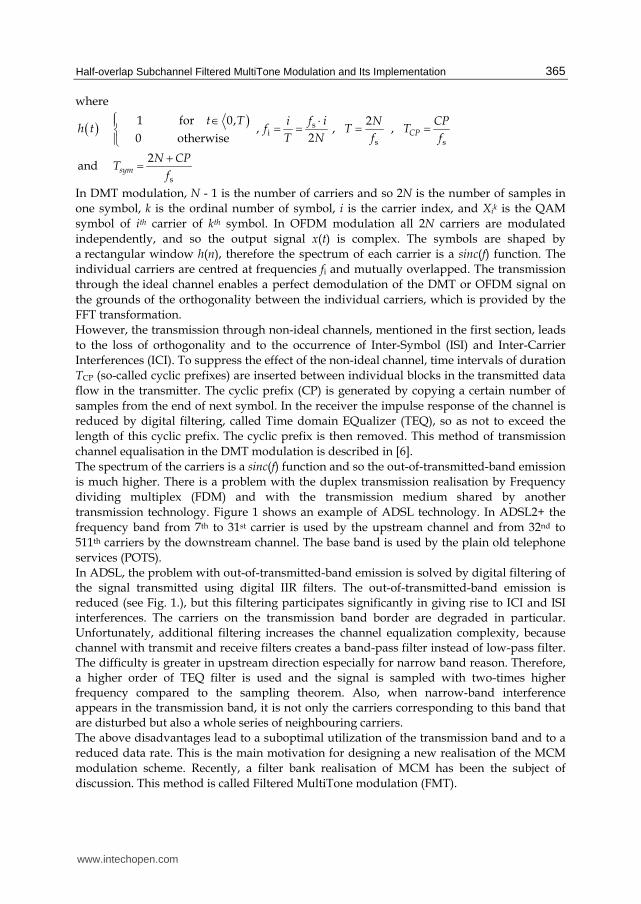
The spectrum of the carriers is a sinc(f) function and so the out-of-transmitted-band emission
is much higher. There is a problem with the duplex transmission realisation by Frequency
dividing multiplex (FDM) and with the transmission medium shared by another
transmission technology. Figure 1 shows an example of ADSL technology. In ADSL2+ the
frequency band from 7th to 31st carrier is used by the upstream channel and from 32nd to
511th carriers by the downstream channel. The base band is used by the plain old telephone
services (POTS). In ADSL, the problem with out-of-transmitted-band emission is solved by digital filtering of the signal transmitted using digital IIR filters. The out-of-transmitted-band emission is reduced (see Fig. 1.), but this filtering participates significantly in giving rise to ICI and ISI interferences. The carriers on the transmission band border are degraded in particular. Unfortunately, additional filtering increases the channel equalization complexity, because channel with transmit and receive filters creates a band-pass filter instead of low-pass filter. The difficulty is greater in upstream direction especially for narrow band reason. Therefore, a higher order of TEQ filter is used and the signal is sampled with two-times higher frequency compared to the sampling theorem. Also, when narrow-band interference appears in the transmission band, it is not only the carriers corresponding to this band that are disturbed but also a whole series of neighbouring carriers. The above disadvantages lead to a suboptimal utilization of the transmission band and to a
reduced data rate. This is the main motivation for designing a new realisation of the MCM
modulation scheme. Recently, a filter bank realisation of MCM has been the subject of
discussion. This method is called Filtered MultiTone modulation (FMT).
www.intechopen.com
Discrete Time Systems
366
Fig. 1. SNR comparison of upstream and part of downstream frequency bands of ADSL2+ technology with and without additional digital filtering. PSD= -40 dBm/Hz, AWGN=-110 dBm/Hz and -40 dB hybrid suppression.
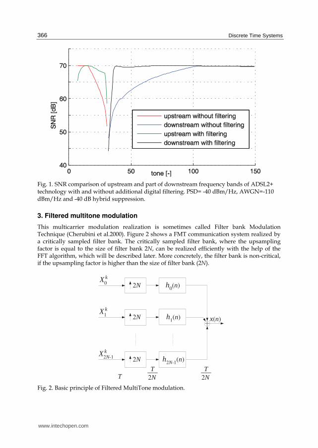
3. Filtered multitone modulation
This multicarrier modulation realization is sometimes called Filter bank Modulation Technique (Cherubini et al.2000). Figure 2 shows a FMT communication system realized by a critically sampled filter bank. The critically sampled filter bank, where the upsampling factor is equal to the size of filter bank 2N, can be realized efficiently with the help of the FFT algorithm, which will be described later. More concretely, the filter bank is non-critical, if the upsampling factor is higher than the size of filter bank (2N).
2N
2N
2N
T 2NT___
X0
k
X1
k
X2N-1k
h0(n)
h1(n)
h2N-1(n)
2NT___
x(n)
Fig. 2. Basic principle of Filtered MultiTone modulation.
www.intechopen.com
Half-overlap Subchannel Filtered MultiTone Modulation and Its Implementation
367
The output signal x(n) of the FMT transmitter given in Fig. 2 can be described using relation:
( ) ( )2 1
0
12
2
Nki i
k i
x n X h n kNN
∞ −=−∞ =
= −∑ ∑ (2)
The polyphase FIR filters with the impulse response hi(n) are the frequency-shifted versions of low pass filter with impulse response h(n), called prototype filter:
( ) ( ) 2πj
21
e2
ni
Nih n h n
N= (3)
In equation (3) h(n) is the impulse response of the prototype FIR filter. The order of this
filter is 2γΝ, where γ is the overlapping factor in the time domain. For a perfect demodulation of received signal after transmission through the ideal channel the prototype filter must be designed such that for the polyphase filters the condition hold, which is expressed by the equation:
( ) ( )* 2i i i i kn
h n h n Nk δ δ′ ′−− =∑ (4)
for 0 ≤ i, i′ ≤ 2N – 1 and k = …, –1, 0, 1, …
In equation (4) δi is the Kronecker delta function. The equation defining the orthogonality between the polyphase filters is a more general form of the Nyquist criterion (Cherubini et al.2000). For example, condition (4) of perfect reconstruction is satisfied in the case of DMT modulation, given in equation (1), because the sinc spectrums of individual carriers have zero-values for the rest of corresponding carriers. The ideal frequency characteristic of the prototype filter to realize a non-overlapped FMT modulation system is given by the equation (5).
( )jπ1 1
1 for -e 2 2
0 otherwise
fT fH T T
⎧ ≤ ≤⎪= ⎨⎪⎩ (5)
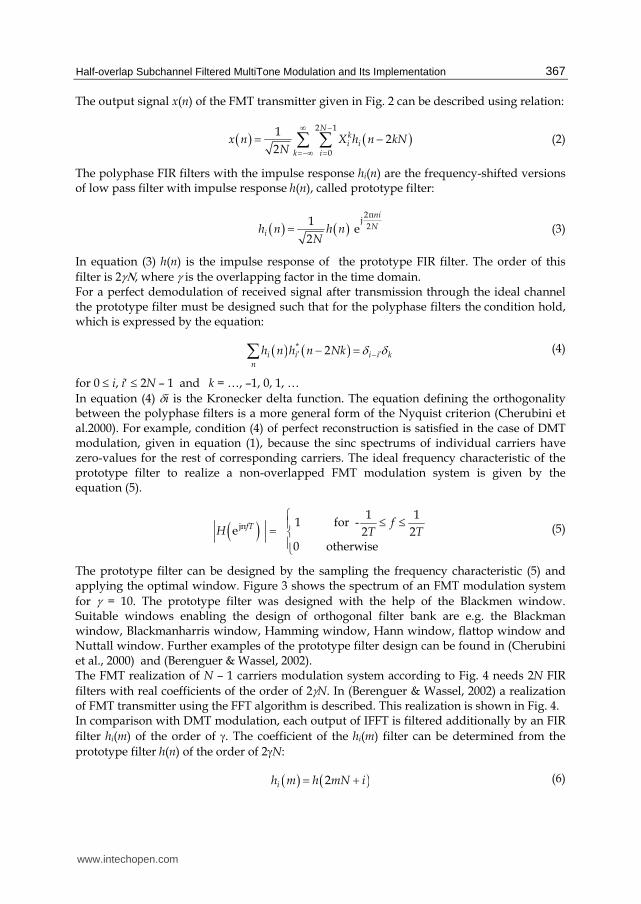
The prototype filter can be designed by the sampling the frequency characteristic (5) and applying the optimal window. Figure 3 shows the spectrum of an FMT modulation system
for γ = 10. The prototype filter was designed with the help of the Blackmen window. Suitable windows enabling the design of orthogonal filter bank are e.g. the Blackman window, Blackmanharris window, Hamming window, Hann window, flattop window and Nuttall window. Further examples of the prototype filter design can be found in (Cherubini et al., 2000) and (Berenguer & Wassel, 2002). The FMT realization of N – 1 carriers modulation system according to Fig. 4 needs 2N FIR
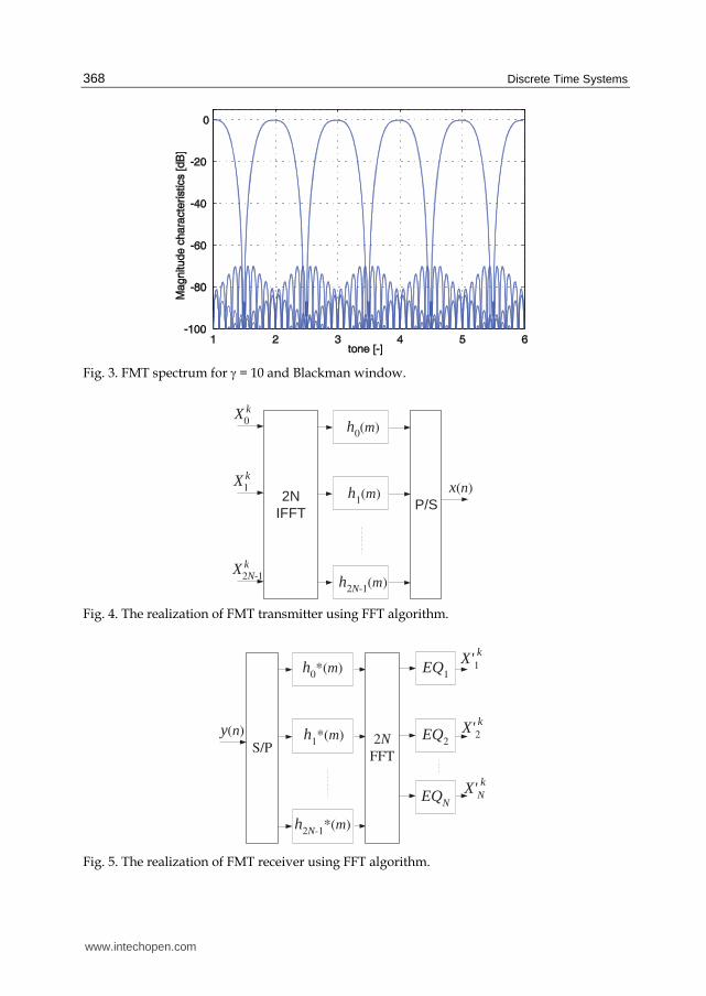
filters with real coefficients of the order of 2γN. In (Berenguer & Wassel, 2002) a realization of FMT transmitter using the FFT algorithm is described. This realization is shown in Fig. 4. In comparison with DMT modulation, each output of IFFT is filtered additionally by an FIR
filter hi(m) of the order of γ. The coefficient of the hi(m) filter can be determined from the
prototype filter h(n) of the order of 2γN:
( ) ( )2ih m h mN i= + (6)
www.intechopen.com
Discrete Time Systems
368
Fig. 3. FMT spectrum for γ = 10 and Blackman window.
X0
k
X1
k
X2N-1k
h0(m)
h1(m)
h2N-1(m)
x(n)2N
IFFTP/S
Fig. 4. The realization of FMT transmitter using FFT algorithm.
X'1
k
y(n)S/P
h0*(m)
h1*(m)
h2N-1*(m)
2NFFT
EQ1
EQ2
EQN
X'2
X'N
k
k
Fig. 5. The realization of FMT receiver using FFT algorithm.
www.intechopen.com
Half-overlap Subchannel Filtered MultiTone Modulation and Its Implementation
369
The principle of FMT signal demodulation can be seen in fig 5. Since the individual carriers are completely separated, no ICI interference occurs. Equalization to minimize ISI interference can be performed in the frequency domain without the application of cyclic prefix (Benvenuto et al., 2002). Duplex transmission can be solved by both FDM and EC, without any further filtering, which is the case of DMT. If a part of the frequency band is shared (EC duplex method), the echo cancellation can be realized easily in the frequency domain.
4. Overlapped FMT modulation
The FMT modulation type mentioned in the previous section can be called non-overlapped FMT modulation. The individual carriers are completely separated and do not overlap each other. FMT realization of multicarrier modulation offers a lot of advantages, as mentioned in the preceding chapter. In particular, the frequency band provided is better utilized in the border parts of the spectrum designed for individual transmission directions, where in the case of DMT there are losses in the transmission rate. The out-of-transmission-band emission is eliminated almost completely. If we use the EC duplex method, the simpler suppression of echo signal enables sharing a higher frequency band. A disadvantage of FMT
modulation is the increase in transmission delay, which increases with the filter order γ. The
FMT transmission delay is minimally γ times higher than the transmission delay of a
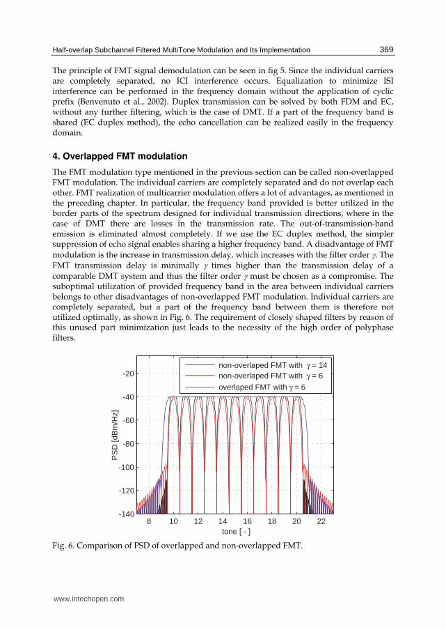
comparable DMT system and thus the filter order γ must be chosen as a compromise. The suboptimal utilization of provided frequency band in the area between individual carriers belongs to other disadvantages of non-overlapped FMT modulation. Individual carriers are completely separated, but a part of the frequency band between them is therefore not utilized optimally, as shown in Fig. 6. The requirement of closely shaped filters by reason of this unused part minimization just leads to the necessity of the high order of polyphase filters.
8 10 12 14 16 18 20 22 -140
-120
-100
-80
-60
-40
-20
tone [ - ]
PS
D [d
Bm
/Hz]
non-overlaped FMT with γ = 14non-overlaped FMT with γ = 6
overlaped FMT with γ = 6
Fig. 6. Comparison of PSD of overlapped and non-overlapped FMT.
www.intechopen.com
Discrete Time Systems
370
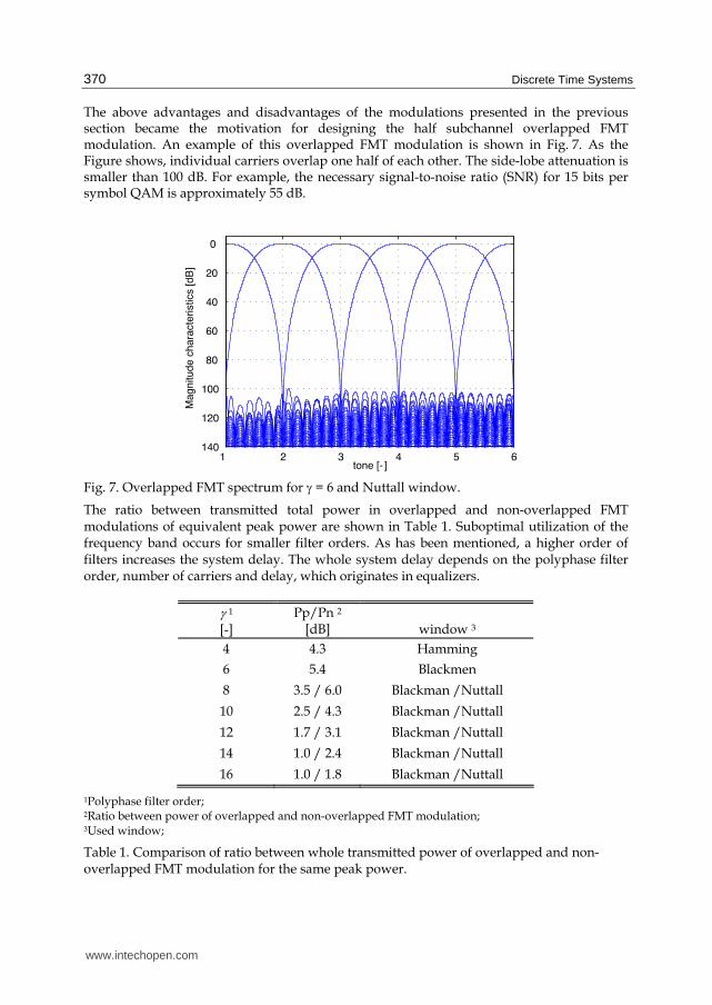
The above advantages and disadvantages of the modulations presented in the previous section became the motivation for designing the half subchannel overlapped FMT modulation. An example of this overlapped FMT modulation is shown in Fig. 7. As the Figure shows, individual carriers overlap one half of each other. The side-lobe attenuation is smaller than 100 dB. For example, the necessary signal-to-noise ratio (SNR) for 15 bits per symbol QAM is approximately 55 dB.
1 2 3 4 5 6140
120
100
80
60
40
20
0
tone [- ]
Mag
nitu
de c
hara
cter
istic
s [d
B]
Fig. 7. Overlapped FMT spectrum for γ = 6 and Nuttall window.
The ratio between transmitted total power in overlapped and non-overlapped FMT modulations of equivalent peak power are shown in Table 1. Suboptimal utilization of the frequency band occurs for smaller filter orders. As has been mentioned, a higher order of filters increases the system delay. The whole system delay depends on the polyphase filter order, number of carriers and delay, which originates in equalizers.
γ 1
[-] Pp/Pn 2
[dB]
window 3
4 4.3 Hamming
6 5.4 Blackmen
8 3.5 / 6.0 Blackman /Nuttall
10 2.5 / 4.3 Blackman /Nuttall
12 1.7 / 3.1 Blackman /Nuttall
14 1.0 / 2.4 Blackman /Nuttall
16 1.0 / 1.8 Blackman /Nuttall
1Polyphase filter order; 2Ratio between power of overlapped and non-overlapped FMT modulation; 3Used window;
Table 1. Comparison of ratio between whole transmitted power of overlapped and non-overlapped FMT modulation for the same peak power.
www.intechopen.com
Half-overlap Subchannel Filtered MultiTone Modulation and Its Implementation
371
The designed filter has to meet the orthogonal condition, introduced by equation (4). An
efficient realization of overlapped FMT modulation is the same as that of non overlapped
FMT modulation introduced in Fig. 4. The difference is in the design of the filter coefficients
only. Polyphase filters can be of a considerably lower order than filters in non-overlapped
FMT modulation, because they need not be so closely shaped in the transient part. The
shape of individual filters must be designed so as to obtain a flat power spectral density
(PSD) in the frequency band utilized, because it enables an optimal utilization of the
frequency band provided. Figure 7 shows an example of such overlapped FMT modulation
with γ = 6. The ideal frequency characteristic of overlapped FMT prototype filter can be
defined with the help of two conditions:
( )( ) ( )( )
jπ
22jπ 1/2jπ
1e 0 for
2
1e e 1 for
2
fT
f Tf T
H fT
H H fT
+
= ≤+ = >
(7)
In the design of polyphase filters of very low order it is necessary to chose a compromise
between both conditions, i.e. between the ripple in the band used and the stopband
attenuation. Examples of some design results for polyphase filter orders of 2, 4 and 6 are
shown in (Silhavy, 2008). The filter design method based on the prototype filter was
described in the previous chapter.
5. Equalization in overlapped FMT modulation
In overlapped FMT modulation as well as in non-overlapped FMT modulation the inter-
symbol interferences (ISI) occur even on an ideal channel, which is given by the FMT
modulation system principle. Equalization for ISI interference elimination can be solved in
the same manner as in non-overlapped FMT modulation with the help of DFE equalizers, in
the frequency domain (see Fig. 5).
If the prototype filter was designed to satisfy orthogonal condition (4), ICI interferences do
not occur even in overlapped FMT modulation. More exactly, the ICI interference level is
comparable with non-overlapped FMT modulation. This is demonstrated by the simulation
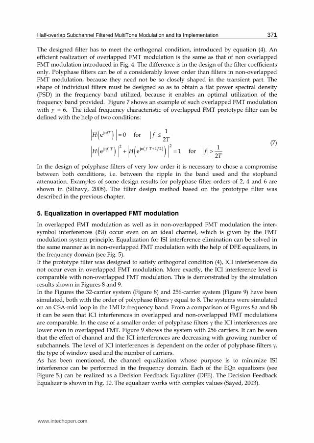
results shown in Figures 8 and 9.
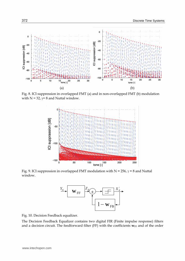
In the Figures the 32-carrier system (Figure 8) and 256-carrier system (Figure 9) have been
simulated, both with the order of polyphase filters γ equal to 8. The systems were simulated
on an CSA-mid loop in the 1MHz frequency band. From a comparison of Figures 8a and 8b
it can be seen that ICI interferences in overlapped and non-overlapped FMT modulations
are comparable. In the case of a smaller order of polyphase filters γ the ICI interferences are
lower even in overlapped FMT. Figure 9 shows the system with 256 carriers. It can be seen
that the effect of channel and the ICI interferences are decreasing with growing number of
subchannels. The level of ICI interferences is dependent on the order of polyphase filters γ,
the type of window used and the number of carriers.
As has been mentioned, the channel equalization whose purpose is to minimize ISI
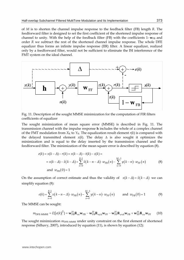
interference can be performed in the frequency domain. Each of the EQn equalizers (see
Figure 5.) can be realized as a Decision Feedback Equalizer (DFE). The Decision Feedback
Equalizer is shown in Fig. 10. The equalizer works with complex values (Sayed, 2003).
www.intechopen.com
Discrete Time Systems
372
(a) (b)
Fig. 8. ICI suppression in overlapped FMT (a) and in non-overlapped FMT (b) modulation
with N = 32, γ= 8 and Nuttal window.
Fig. 9. ICI suppression in overlapped FMT modulation with N = 256, γ = 8 and Nuttal window.
+FFw
FB1 w−
KY /
KX KZ
Fig. 10. Decision Feedback equalizer.
The Decision Feedback Equalizer contains two digital FIR (Finite impulse response) filters and a decision circuit. The feedforward filter (FF) with the coefficients wFF and of the order
www.intechopen.com
Half-overlap Subchannel Filtered MultiTone Modulation and Its Implementation
373
of M is to shorten the channel impulse response to the feedback filter (FB) length R. The feedforward filter is designed to set the first coefficient of the shortened impulse response of channel to unity. With the help of the feedback filter (FB) with the coefficients 1- wFB and order R we subtract the rest of the shortened channel impulse response. The whole DFE equalizer thus forms an infinite impulse response (IIR) filter. A linear equalizer, realized only by a feedforward filter, would not be sufficient to eliminate the ISI interference of the FMT system on the ideal channel.
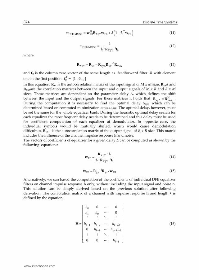
Fig. 11. Description of the sought MMSE minimization for the computation of FIR filters coefficients of equalizer
The sought minimization of mean square error (MMSE) is described in Fig. 11. The transmission channel with the impulse response h includes the whole of a complex channel of the FMT modulation from XK to YK. The equalization result element r(k) is compared with
the delayed transmitted element x(k). The delay Δ is also sought it optimizes the minimization and is equal to the delay inserted by the transmission channel and the feedforward filter. The minimization of the mean square error is described by equation (8).
( ) ( ) ( ) ( ) ( )( )
-1 1
FB FF0 0
FB
( ) ( ) ( ) ( ) ( ) ( )
ˆ ˆ ( )
and 0 1
R M
n n
e k x k Δ r k x k Δ t k z k
x k Δ x k Δ x k n Δ w n y k n w n
w
−= =
= − − = − − − == − − − + − − ⋅ − − ⋅
=∑ ∑ (8)
On the assumption of correct estimate and thus the validity of ( )ˆ( )x k Δ x k Δ− = − we can
simplify equation (8):
( ) ( ) ( ) ( ) ( )-1 1
FB FF FB0 0
( ) and 0 1R M
n n
e k x k n Δ w n y k n w n w−
= == − − ⋅ − − ⋅ =∑ ∑ (9)
The MMSE can be sought:
2 H H H H
DFE-MMSE FB xx FB FB xyΔ FF FF yxΔ FB FF yy FF{ ( ) }m E e k= = − − +w R w w R w w R w w R w (10)
The sought minimization mDFE-MMSE under unity constraint on the first element of shortened response (Silhavy, 2007), introduced by equation (11), is shown by equation (12):
www.intechopen.com
Discrete Time Systems
374
( )H TDFE-MMSE FB X|Y FB 0 FB1m λ= + −w R w f w (11)
DFE-MMSE T 10 X|Y 0
1m −=
f R f (12)
where
1X|Y xx xyΔ yy yxΔ
−= −R R R R R (13)
and f0 is the column zero vector of the same length as feedforward filter R with element
one in the first position: T0 R-1[1 ]=f 0
In this equation, Rxx is the autocorrelation matrix of the input signal of M x M size, RxyΔ and Ryx∆are the correlation matrices between the input and output signals of M x R and R x M
sizes. These matrices are dependent on the parameter delay Δ, which defines the shift between the input and the output signals. For these matrices it holds that .
During the computation it is necessary to find the optimal delay Δopt, which can be determined based on computed minimization mDFE-MMSE. The optimal delay, however, must be set the same for the whole equalizer bank. During the heuristic optimal delay search for each equalizer the most frequent delay needs to be determined and this delay must be used for coefficient computation of each equalizer of demodulator. In opposite case, the individual symbols would be mutually shifted, which would cause demodulation difficulties. Ryy is the autocorrelation matrix of the output signal of R x R size. This matrix includes the influence of the channel impulse response h and noise.
The vectors of coefficients of equalizer for a given delay Δ can be computed as shown by the following equations:
1
X|Y 0FB T 1
0 X|Y 0
−−= R f
wf R f
(14)
1FF yy yxΔ FB
−=w R R w (15)
Alternatively, we can based the computation of the coefficients of individual DFE equalizer filters on channel impulse response h only, without including the input signal and noise n. This solution can be simply derived based on the previous solution after following derivation. The convolution matrix of a channel with impulse response h and length k is defined by the equation:
0
1 0
1 2
1 1
1
0 0
0
0
0 0
k k k M
k k M
k
h
h h
h h h
h h
h
− − −− − +
−
⎡ ⎤⎢ ⎥⎢ ⎥⎢ ⎥⎢ ⎥= ⎢ ⎥⎢ ⎥⎢ ⎥⎢ ⎥⎢ ⎥⎣ ⎦
H
AA
B B D BAA
B B D BA
(16)
HxyΔ yxΔ=R R
www.intechopen.com
Half-overlap Subchannel Filtered MultiTone Modulation and Its Implementation
375
From this matrix we chose the shortened part in the terms of delay Δ with the help of vector G:
( )diag 0, , 0, 1, , 1, 0, , 0=G … … …
Δ R
k +M–1 samples
(17)
The sought matrix RX|Y , introduced by equation (13), of the Zero-forcing solution is shown by equation (18):
( ) 1
X|Y_ZeroForce
−= − ⋅H H HR I GH H H H G (18)
The approach presented enables determining the individual equalizer filter coefficients from the channel impulse response h only. The matrix G determines the maximized area and thus
the delay Δ between the input and the output signals. In some cassis the matrix RX|Y_ZeroForce
is not invertible. This problem can be fixed by increasing the components in the main diagonal, as shows by the equation:
( ){ }opt max diagk= + ⋅ ⋅A A A I (19)
where max{daig(A)} is the maximal element of the main diagonal of matrix A, and kopt is the optimization factor, which can be increased in several steps (e.g. 10-10, 10-8, 10-6, ...).
010
2030
40
0
10
20
30
40
10-10
10-5
100
R [ - ]
MS
E [
- ]
M [ - ]
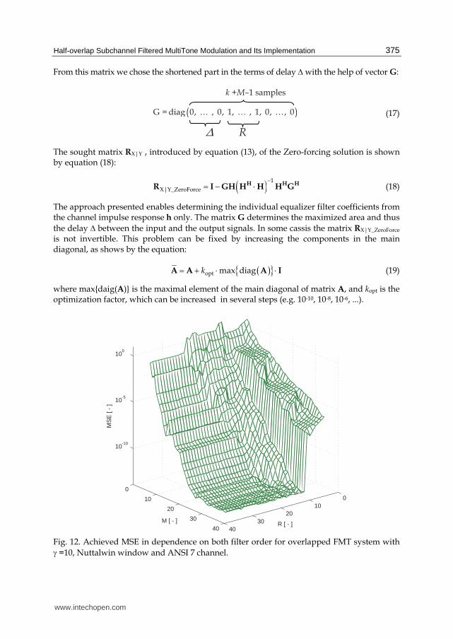
Fig. 12. Achieved MSE in dependence on both filter order for overlapped FMT system with
γ =10, Nuttalwin window and ANSI 7 channel.
www.intechopen.com
Discrete Time Systems
376
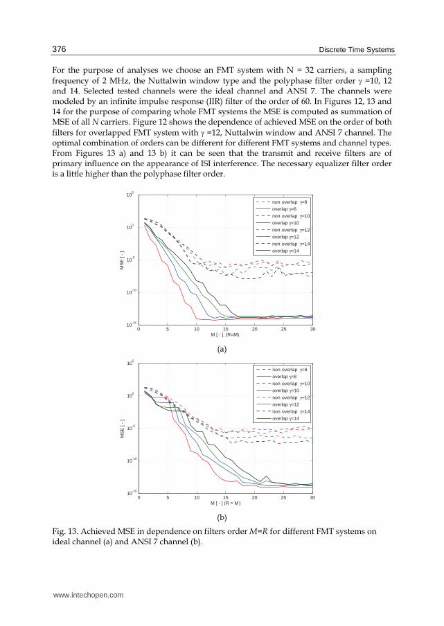
For the purpose of analyses we choose an FMT system with N = 32 carriers, a sampling
frequency of 2 MHz, the Nuttalwin window type and the polyphase filter order γ =10, 12 and 14. Selected tested channels were the ideal channel and ANSI 7. The channels were modeled by an infinite impulse response (IIR) filter of the order of 60. In Figures 12, 13 and 14 for the purpose of comparing whole FMT systems the MSE is computed as summation of MSE of all N carriers. Figure 12 shows the dependence of achieved MSE on the order of both
filters for overlapped FMT system with γ =12, Nuttalwin window and ANSI 7 channel. The optimal combination of orders can be different for different FMT systems and channel types. From Figures 13 a) and 13 b) it can be seen that the transmit and receive filters are of primary influence on the appearance of ISI interference. The necessary equalizer filter order is a little higher than the polyphase filter order.
0 5 10 15 20 25 3010
-15
10-10
10-5
100
105
M [ - ], (R=M)
MS
E [
- ]
non overlap γ=8
overlap γ=8
non overlap γ=10
overlap γ=10
non overlap γ=12
overlap γ=12
non overlap γ=14
overlap γ=14
(a)
0 5 10 15 20 25 3010
-15
10-10
10-5
100
105
M [ - ] (R = M )
MS
E [
- ]
non overlap γ=8
overlap γ=8
non overlap γ=10
overlap γ=10
non overlap γ=12
overlap γ=12
non overlap γ=14
overlap γ=14
(b)
Fig. 13. Achieved MSE in dependence on filters order M=R for different FMT systems on ideal channel (a) and ANSI 7 channel (b).
www.intechopen.com
Half-overlap Subchannel Filtered MultiTone Modulation and Its Implementation
377
6. Implementation of Filtered MultiTone in Matlab and on DSP
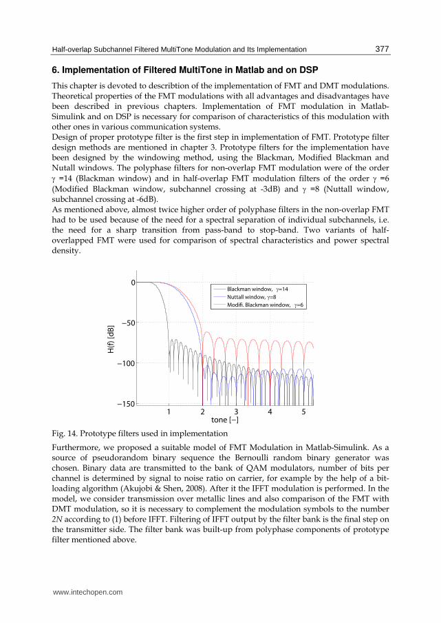
This chapter is devoted to describtion of the implementation of FMT and DMT modulations. Theoretical properties of the FMT modulations with all advantages and disadvantages have been described in previous chapters. Implementation of FMT modulation in Matlab-Simulink and on DSP is necessary for comparison of characteristics of this modulation with other ones in various communication systems. Design of proper prototype filter is the first step in implementation of FMT. Prototype filter design methods are mentioned in chapter 3. Prototype filters for the implementation have been designed by the windowing method, using the Blackman, Modified Blackman and Nutall windows. The polyphase filters for non-overlap FMT modulation were of the order
γ =14 (Blackman window) and in half-overlap FMT modulation filters of the order γ =6
(Modified Blackman window, subchannel crossing at -3dB) and γ =8 (Nuttall window, subchannel crossing at -6dB). As mentioned above, almost twice higher order of polyphase filters in the non-overlap FMT had to be used because of the need for a spectral separation of individual subchannels, i.e. the need for a sharp transition from pass-band to stop-band. Two variants of half-overlapped FMT were used for comparison of spectral characteristics and power spectral density.
1 2 3 4 5−150
−100
−50
0
tone [−]
H(f
) [d
B]
Blackman window, =14
Nuttall window, =8
Modifi. Blackman window, =6
Fig. 14. Prototype filters used in implementation
Furthermore, we proposed a suitable model of FMT Modulation in Matlab-Simulink. As a source of pseudorandom binary sequence the Bernoulli random binary generator was chosen. Binary data are transmitted to the bank of QAM modulators, number of bits per channel is determined by signal to noise ratio on carrier, for example by the help of a bit-loading algorithm (Akujobi & Shen, 2008). After it the IFFT modulation is performed. In the model, we consider transmission over metallic lines and also comparison of the FMT with DMT modulation, so it is necessary to complement the modulation symbols to the number 2N according to (1) before IFFT. Filtering of IFFT output by the filter bank is the final step on the transmitter side. The filter bank was built-up from polyphase components of prototype filter mentioned above.
www.intechopen.com
Discrete Time Systems
378
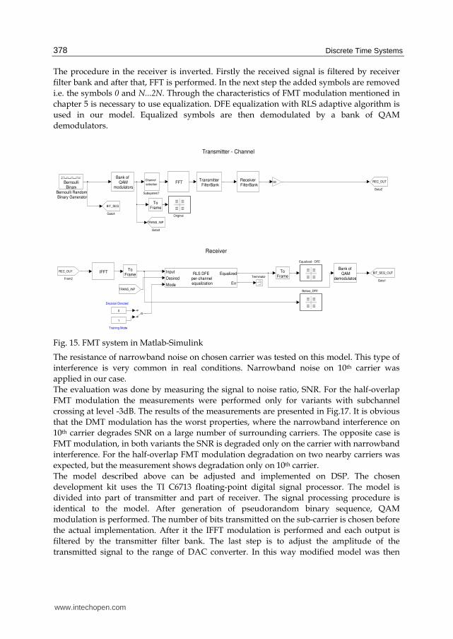
The procedure in the receiver is inverted. Firstly the received signal is filtered by receiver
filter bank and after that, FFT is performed. In the next step the added symbols are removed
i.e. the symbols 0 and N...2N. Through the characteristics of FMT modulation mentioned in
chapter 5 is necessary to use equalization. DFE equalization with RLS adaptive algorithm is
used in our model. Equalized symbols are then demodulated by a bank of QAM
demodulators.
Fig. 15. FMT system in Matlab-Simulink
The resistance of narrowband noise on chosen carrier was tested on this model. This type of
interference is very common in real conditions. Narrowband noise on 10th carrier was
applied in our case.
The evaluation was done by measuring the signal to noise ratio, SNR. For the half-overlap
FMT modulation the measurements were performed only for variants with subchannel
crossing at level -3dB. The results of the measurements are presented in Fig.17. It is obvious
that the DMT modulation has the worst properties, where the narrowband interference on
10th carrier degrades SNR on a large number of surrounding carriers. The opposite case is
FMT modulation, in both variants the SNR is degraded only on the carrier with narrowband
interference. For the half-overlap FMT modulation degradation on two nearby carriers was
expected, but the measurement shows degradation only on 10th carrier.
The model described above can be adjusted and implemented on DSP. The chosen
development kit uses the TI C6713 floating-point digital signal processor. The model is
divided into part of transmitter and part of receiver. The signal processing procedure is
identical to the model. After generation of pseudorandom binary sequence, QAM
modulation is performed. The number of bits transmitted on the sub-carrier is chosen before
the actual implementation. After it the IFFT modulation is performed and each output is
filtered by the transmitter filter bank. The last step is to adjust the amplitude of the
transmitted signal to the range of DAC converter. In this way modified model was then
Decision Directed
Training Mode
Transmitter - Channel
Receiver
Terminator
Subsystem7
Channel
selection
RLS DFE per-channel equalization
Equalized
Err
Input
Desired
Mode
Bank of QAM
modulators
Transmitter FilterBank
IFFTBank of QAM
demodulators
Receiver FilterBank
OriginalGoto4
BIT_SEQ
Goto3
TRANS_INP
Goto2
REC_OUT
Goto1
BIT_SEQ_OUT
30
TRANS_INP
From2
REC_OUT ToFrame
ToFrame
ToFrame
FFT
Equalized - DFE
1
0
Bernoulli RandomBinary Generator
BernoulliBinary
Before_DFE
www.intechopen.com
Half-overlap Subchannel Filtered MultiTone Modulation and Its Implementation
379
compiled and implemented on digital signal processor with the help of the Link for CCS
toolbox.
This way of generating code is fully functional and they allow measuring the proposed algorithm directly in the digital signal processor but they definitely cannot be considered optimized. It is convenient to use libraries that are optimized for a given processor and replace the standard Simulink blocks by optimized ones. It is also possible to replace the original number formats by formats corresponding to the processor. Also the filterbank can be designed in two ways. The first way is independent filtering in each branch of filterbank (Sysel, Krajsa 2010).
h1
1h1
2h1
3h1
2Nh2
1h2
2h2
3h2
2Nh3
1h3
2h3
3h3
2Nhγ
1hγ
2hγ
3hγ
2N
o2N
io1
i
o2
io3
i
X1
i+1X2
i+1X3
i+1X2N
i+1
X1
i+2X2
i+2X3
i+2X2N
i+2X1
i+3X2
i+3X3
i+3X2N
i+3
X1
i+2N
X2
i+2N
X3
i+2N
X2N
i+2N
a)
b)
c)
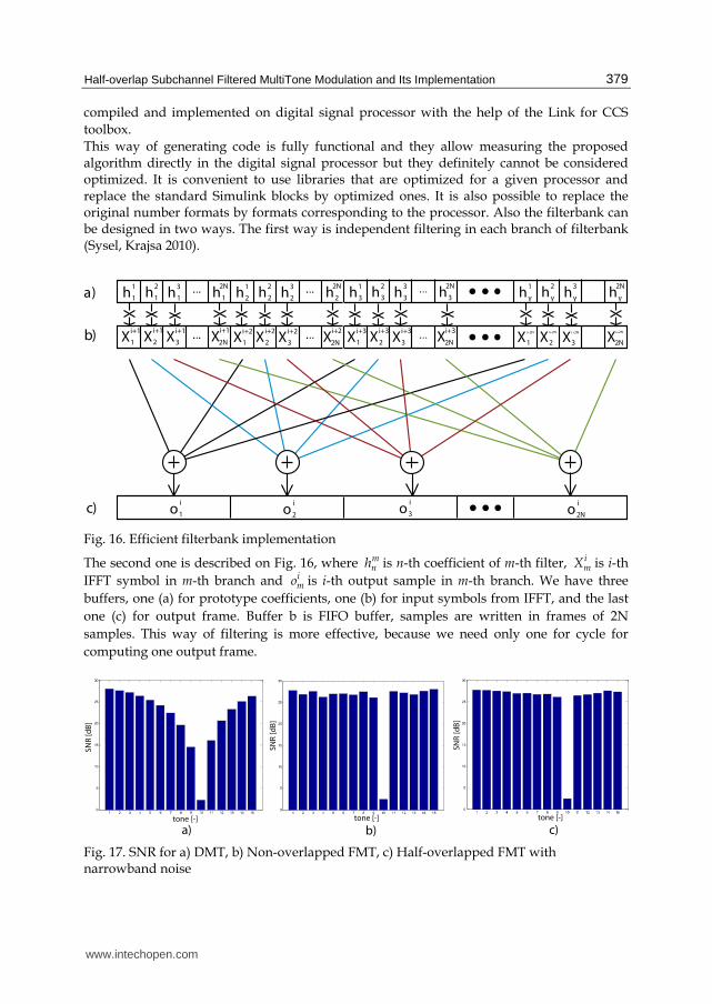
Fig. 16. Efficient filterbank implementation
The second one is described on Fig. 16, where mnh is n-th coefficient of m-th filter, i
mX is i-th
IFFT symbol in m-th branch and imo is i-th output sample in m-th branch. We have three
buffers, one (a) for prototype coefficients, one (b) for input symbols from IFFT, and the last
one (c) for output frame. Buffer b is FIFO buffer, samples are written in frames of 2N
samples. This way of filtering is more effective, because we need only one for cycle for
computing one output frame.
tone [-]
SN
R [
dB
]
a)tone [-]
SN
R [
dB
]
b)tone [-]
SN
R [
dB
]
c)
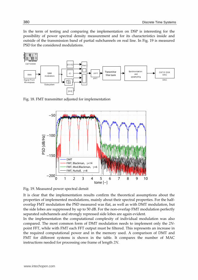
Fig. 17. SNR for a) DMT, b) Non-overlapped FMT, c) Half-overlapped FMT with narrowband noise
www.intechopen.com
Discrete Time Systems
380
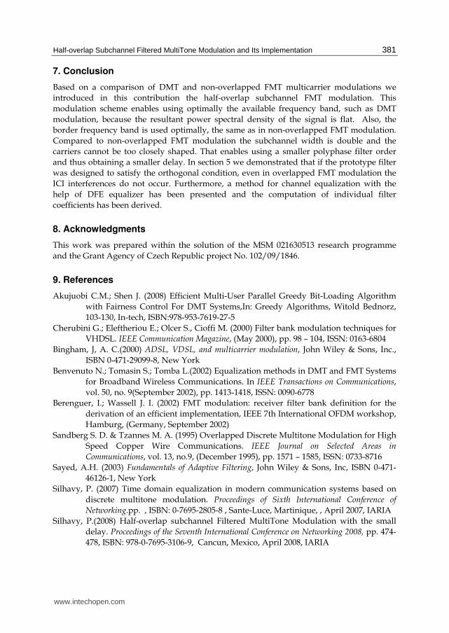
In the term of testing and comparing the implementation on DSP is interesting for the possibility of power spectral density measurement and for its characteristics inside and outside of the transmission band of partial subchannels on real line. In Fig. 19 is measured PSD for the considered modulations.
Synchronizat ion
and
upsam pling
Transmitter
filter bankQAM
modulators
Subsystem
data
Signal Fro m
W o rkspace
Vert C
I FFT
IFFT
C6713 DSK
DAC
DAC
[0 0]
[0 0 0]
-C-
C6713 DSK
Fig. 18. FMT transmitter adjusted for implementation
0 1 2 3 4 5 6 7 8 9 10−200
−150
−100
−50
tone [−]
PS
D [
dB
/Hz]
DMT
FMT, Blackman, γ=14
FMT, Mod.Blackman, γ=6
FMT, Nuttall, γ=8
Fig. 19. Measured power spectral densit
It is clear that the implementation results confirm the theoretical assumptions about the
properties of implemented modulations, mainly about their spectral properties. For the half-
overlap FMT modulation the PSD measured was flat, as well as with DMT modulation, but
the side lobes are suppressed by up to 50 dB. For the non-overlap FMT modulation perfectly
separated subchannels and strongly repressed side lobes are again evident.
In the implementation the computational complexity of individual modulation was also
compared. The most common form of DMT modulation needs to implement only the 2N-
point FFT, while with FMT each FFT output must be filtered. This represents an increase in
the required computational power and in the memory used. A comparison of DMT and
FMT for different systems is shown in the table. It compares the number of MAC
instructions needed for processing one frame of length 2N.
www.intechopen.com
Half-overlap Subchannel Filtered MultiTone Modulation and Its Implementation
381
7. Conclusion
Based on a comparison of DMT and non-overlapped FMT multicarrier modulations we
introduced in this contribution the half-overlap subchannel FMT modulation. This
modulation scheme enables using optimally the available frequency band, such as DMT
modulation, because the resultant power spectral density of the signal is flat. Also, the
border frequency band is used optimally, the same as in non-overlapped FMT modulation.
Compared to non-overlapped FMT modulation the subchannel width is double and the
carriers cannot be too closely shaped. That enables using a smaller polyphase filter order
and thus obtaining a smaller delay. In section 5 we demonstrated that if the prototype filter
was designed to satisfy the orthogonal condition, even in overlapped FMT modulation the
ICI interferences do not occur. Furthermore, a method for channel equalization with the
help of DFE equalizer has been presented and the computation of individual filter
coefficients has been derived.
8. Acknowledgments
This work was prepared within the solution of the MSM 021630513 research programme
and the Grant Agency of Czech Republic project No. 102/09/1846.
Silhavy, P.(2008) Half-overlap subchannel Filtered MultiTone Modulation with the small
delay. Proceedings of the Seventh International Conference on Networking 2008, pp. 474-
478, ISBN: 978-0-7695-3106-9, Cancun, Mexico, April 2008, IARIA
www.intechopen.com
Discrete Time Systems
382
Sysel, P.; Krajsa, O.(2010) Optimization of FIR filter implementation for FMT on VLIW DSP. Proceedings of the 4th International Conference on Circuits, Systems and Signals (CSS'10). ISBN: 978-960-474-208- 0, Corfu, 2010 WSEAS Press
www.intechopen.com
Discrete Time SystemsEdited by Dr. Mario Alberto Jordán
ISBN 978-953-307-200-5Hard cover, 526 pagesPublisher InTechPublished online 26, April, 2011Published in print edition April, 2011
InTech ChinaUnit 405, Office Block, Hotel Equatorial Shanghai No.65, Yan An Road (West), Shanghai, 200040, China Phone: +86-21-62489820 Fax: +86-21-62489821
Discrete-Time Systems comprehend an important and broad research field. The consolidation of digital-basedcomputational means in the present, pushes a technological tool into the field with a tremendous impact inareas like Control, Signal Processing, Communications, System Modelling and related Applications. This bookattempts to give a scope in the wide area of Discrete-Time Systems. Their contents are grouped convenientlyin sections according to significant areas, namely Filtering, Fixed and Adaptive Control Systems, StabilityProblems and Miscellaneous Applications. We think that the contribution of the book enlarges the field of theDiscrete-Time Systems with signification in the present state-of-the-art. Despite the vertiginous advance in thefield, we also believe that the topics described here allow us also to look through some main tendencies in thenext years in the research area.
How to referenceIn order to correctly reference this scholarly work, feel free to copy and paste the following:
Pavel Silhavy and Ondrej Krajsa (2011). Half-overlap Subchannel Filtered MultiTone Modulation and ItsImplementation, Discrete Time Systems, Dr. Mario Alberto Jordán (Ed.), ISBN: 978-953-307-200-5, InTech,Available from: http://www.intechopen.com/books/discrete-time-systems/half-overlap-subchannel-filtered-multitone-modulation-and-its-implementation