IEC 60598-1 Edition 7.0 2008-04 INTERNATIONAL STANDARD NORME INTERNATIONALE Luminaires – Part 1: General requirements and tests Luminaires – Partie 1: Exigences générales et essais IEC 60598-1:2008 Dit document mag slechts op een stand-alone PC worden geïnstalleerd. Gebruik op een netwerk is alleen toegestaan als een aanvullende licentieovereenkomst voor netwerkgebruik met NEN is afgesloten. This document may only be used on a stand-alone PC. Use in a network is only permitted when a supplementary license agreement for use in a network with NEN has been concluded. Dit document is door NEN onder licentie verstrekt aan: / This document has been supplied under license by NEN to: Kema Nederland B.V. E. Cremers-Smit 2008/04/28
Transcript
IEC 60598-1Edition 7.0 2008-04
INTERNATIONAL STANDARD NORME INTERNATIONALE
Luminaires – Part 1: General requirements and tests Luminaires – Partie 1: Exigences générales et essais
IEC
605
98-1
:200
8
Dit
do
cum
ent
mag
sle
chts
op
een
sta
nd
-alo
ne
PC
wo
rden
geï
nst
alle
erd
. Geb
ruik
op
een
net
wer
k is
alle
ento
eges
taan
als
een
aan
vulle
nd
e lic
enti
eove
reen
kom
st v
oo
r n
etw
erkg
ebru
ik m
et N
EN
is a
fges
lote
n.
Th
is d
ocu
men
t m
ay o
nly
be
use
d o
n a
sta
nd
-alo
ne
PC
. Use
in a
net
wo
rk is
on
ly p
erm
itte
d w
hen
asu
pp
lem
enta
ry li
cen
se a
gre
emen
t fo
r u
se in
a n
etw
ork
wit
h N
EN
has
bee
n c
on
clu
ded
.
Dit document is door NEN onder licentie verstrekt aan: / This document has been supplied under license by NEN to:Kema Nederland B.V. E. Cremers-Smit 2008/04/28
IEC Central Office 3, rue de Varembé CH-1211 Geneva 20 Switzerland Email: [email protected] Web: www.iec.ch
About the IEC The International Electrotechnical Commission (IEC) is the leading global organization that prepares and publishes International Standards for all electrical, electronic and related technologies.
About IEC publications The technical content of IEC publications is kept under constant review by the IEC. Please make sure that you have the latest edition, a corrigenda or an amendment might have been published. Catalogue of IEC publications: www.iec.ch/searchpub
The IEC on-line Catalogue enables you to search by a variety of criteria (reference number, text, technical committee,…). It also gives information on projects, withdrawn and replaced publications. IEC Just Published: www.iec.ch/online_news/justpub
Stay up to date on all new IEC publications. Just Published details twice a month all new publications released. Available on-line and also by email. Electropedia: www.electropedia.org
The world's leading online dictionary of electronic and electrical terms containing more than 20 000 terms and definitions in English and French, with equivalent terms in additional languages. Also known as the International Electrotechnical Vocabulary online. Customer Service Centre: www.iec.ch/webstore/custserv
If you wish to give us your feedback on this publication or need further assistance, please visit the Customer Service Centre FAQ or contact us: Email: [email protected] Tel.: +41 22 919 02 11 Fax: +41 22 919 03 00
A propos de la CEI La Commission Electrotechnique Internationale (CEI) est la première organisation mondiale qui élabore et publie des normes internationales pour tout ce qui a trait à l'électricité, à l'électronique et aux technologies apparentées.
A propos des publications CEI Le contenu technique des publications de la CEI est constamment revu. Veuillez vous assurer que vous possédez l’édition la plus récente, un corrigendum ou amendement peut avoir été publié. Catalogue des publications de la CEI: www.iec.ch/searchpub/cur_fut-f.htm
Le Catalogue en-ligne de la CEI vous permet d’effectuer des recherches en utilisant différents critères (numéro de référence, texte, comité d’études,…). Il donne aussi des informations sur les projets et les publications retirées ou remplacées. Just Published CEI: www.iec.ch/online_news/justpub
Restez informé sur les nouvelles publications de la CEI. Just Published détaille deux fois par mois les nouvelles publications parues. Disponible en-ligne et aussi par email. Electropedia: www.electropedia.org
Le premier dictionnaire en ligne au monde de termes électroniques et électriques. Il contient plus de 20 000 termes et définitions en anglais et en français, ainsi que les termes équivalents dans les langues additionnelles. Egalement appelé Vocabulaire Electrotechnique International en ligne. Service Clients: www.iec.ch/webstore/custserv/custserv_entry-f.htm
Si vous désirez nous donner des commentaires sur cette publication ou si vous avez des questions, visitez le FAQ du Service clients ou contactez-nous: Email: [email protected] Tél.: +41 22 919 02 11 Fax: +41 22 919 03 00
Dit document is door NEN onder licentie verstrekt aan: / This document has been supplied under license by NEN to:Kema Nederland B.V. E. Cremers-Smit 2008/04/28
Luminaires – Part 1: General requirements and tests Luminaires – Partie 1: Exigences générales et essais
INTERNATIONAL ELECTROTECHNICAL COMMISSION
COMMISSION ELECTROTECHNIQUE INTERNATIONALE XJICS 29.140.40
PRICE CODECODE PRIX
ISBN 2-8318-9707-6
Dit document is door NEN onder licentie verstrekt aan: / This document has been supplied under license by NEN to:Kema Nederland B.V. E. Cremers-Smit 2008/04/28
0.1 Scope and object ...................................................................................................11 0.2 Normative references ............................................................................................ 12 0.3 General requirements ............................................................................................15 0.4 General test requirements and verification ............................................................. 15 0.5 Components of luminaires .....................................................................................16 0.6 List of parts of IEC 60598-2 ...................................................................................17
SECTION 1: DEFINITIONS
1.1 General .................................................................................................................18 1.2 Definitions .............................................................................................................18
SECTION 2: CLASSIFICATION OF LUMINAIRES
2.1 General .................................................................................................................30 2.2 Classification according to type of protection against electric shock........................ 30 2.3 Classification according to degree of protection against ingress of dust, solid
objects and moisture ............................................................................................. 30 2.4 Classification according to material of supporting surface for which the
luminaire is designed .............................................................................................31 2.5 Classification according to the circumstances of use .............................................. 31
SECTION 3: MARKING
3.1 General .................................................................................................................31 3.2 Marking on luminaires............................................................................................31 3.3 Additional information ............................................................................................35 3.4 Test of marking .....................................................................................................37
SECTION 4: CONSTRUCTION
4.1 General .................................................................................................................38 4.2 Replaceable components .......................................................................................38 4.3 Wireways...............................................................................................................38 4.4 Lampholders..........................................................................................................38 4.5 Starter holders.......................................................................................................40 4.6 Terminal blocks .....................................................................................................40 4.7 Terminals and supply connections .........................................................................40 4.8 Switches................................................................................................................43 4.9 Insulating linings and sleeves ................................................................................43 4.10 Double and reinforced insulation ............................................................................44 4.11 Electrical connections and current-carrying parts ................................................... 45 4.12 Screws and connections (mechanical) and glands.................................................. 46 4.13 Mechanical strength...............................................................................................49 4.14 Suspensions and means of adjustment ..................................................................52 4.15 Flammable materials .............................................................................................55 4.16 Luminaires for mounting on normally flammable surfaces....................................... 56 4.17 Drain holes ............................................................................................................58
Dit document is door NEN onder licentie verstrekt aan: / This document has been supplied under license by NEN to:Kema Nederland B.V. E. Cremers-Smit 2008/04/28
5.1 General .................................................................................................................61 5.2 Supply connection and other external wiring........................................................... 61 5.3 Internal wiring ........................................................................................................66
SECTION 6: Not used
SECTION 7: PROVISION FOR EARTHING
7.1 General .................................................................................................................68 7.2 Provision for earthing.............................................................................................68
SECTION 8: PROTECTION AGAINST ELECTRIC SHOCK
8.1 General .................................................................................................................70 8.2 Protection against electric shock............................................................................ 70
SECTION 9: RESISTANCE TO DUST, SOLID OBJECTS AND MOISTURE
9.1 General .................................................................................................................74 9.2 Tests for ingress of dust, solid objects and moisture .............................................. 74 9.3 Humidity test .........................................................................................................78
SECTION 10: INSULATION RESISTANCE AND ELECTRIC STRENGTH, TOUCH CURRENT AND PROTECTIVE CONDUCTOR CURRENT
10.1 General .................................................................................................................78 10.2 Insulation resistance and electric strength.............................................................. 78
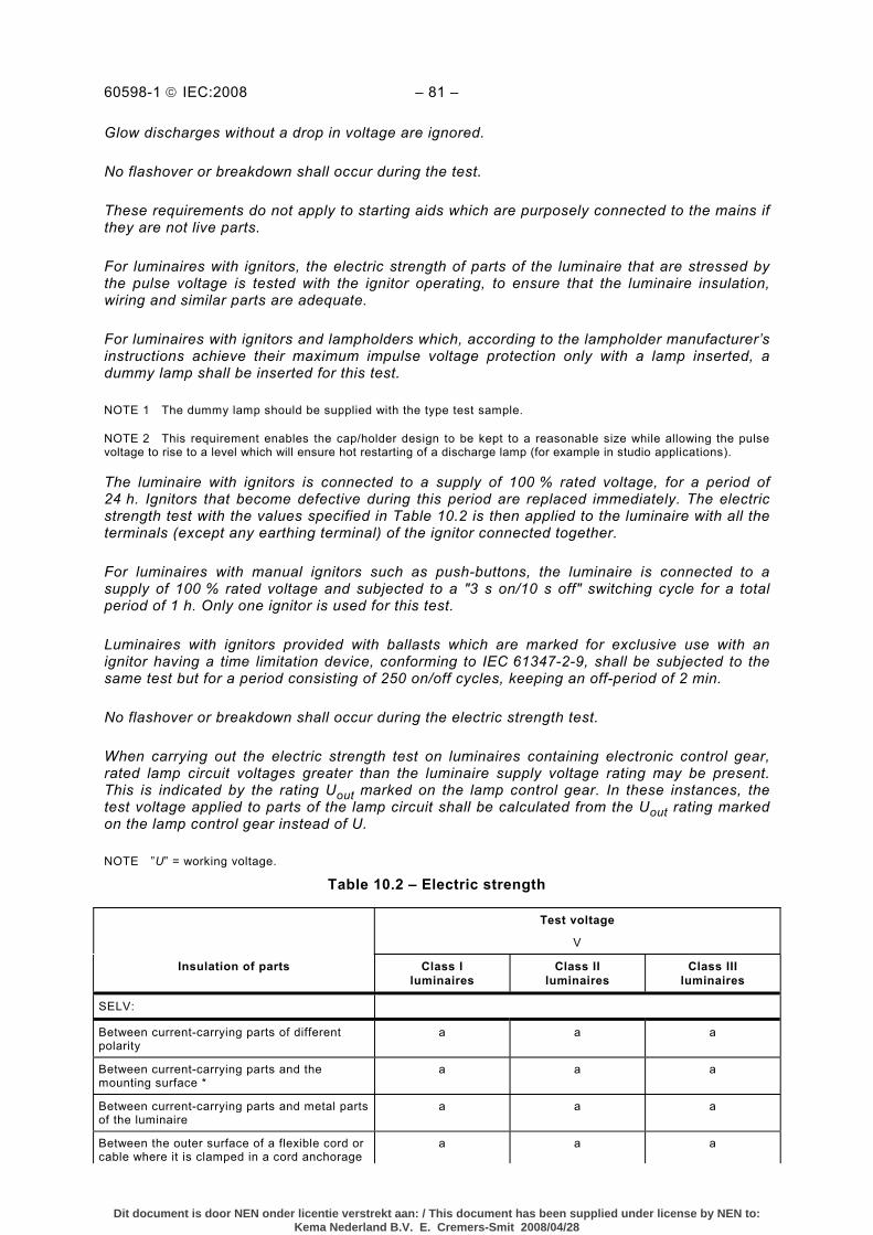
10.2.1 Test – Insulation resistance .......................................................................79 10.2.2 Test – Electric strength .............................................................................. 80
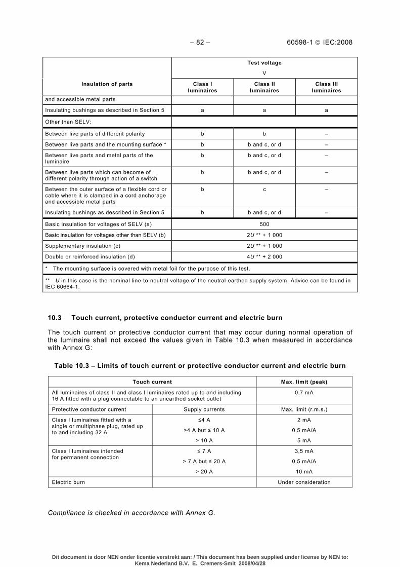
10.3 Touch current, protective conductor current and electric burn................................. 82
SECTION 11: CREEPAGE DISTANCES AND CLEARANCES
11.1 General .................................................................................................................83 11.2 Creepage distances and clearances....................................................................... 83
SECTION 12: ENDURANCE TEST AND THERMAL TEST
12.1 General .................................................................................................................86 12.2 Selection of lamps and ballasts ..............................................................................86 12.3 Endurance test ......................................................................................................86
12.3.1 Test ...........................................................................................................87
Dit document is door NEN onder licentie verstrekt aan: / This document has been supplied under license by NEN to:Kema Nederland B.V. E. Cremers-Smit 2008/04/28
12.3.2 Compliance ...............................................................................................88 12.4 Thermal test (normal operation) .............................................................................88
12.4.1 Test ...........................................................................................................88 12.4.2 Compliance ...............................................................................................90
12.5 Thermal test (abnormal operation) .........................................................................93 12.5.1 Test ...........................................................................................................93 12.5.2 Compliance ...............................................................................................94
12.6 Thermal test (failed windings in lamp control gear) ................................................. 97 12.6.1 Test for luminaires without thermal cut-outs ............................................... 97
12.7 Thermal test in regard to fault conditions in lamp control gear or electronic devices incorporated in thermoplastic luminaires....................................................99 12.7.1 Test for luminaires without temperature sensing controls............................ 99 12.7.2 Test for luminaires with temperature sensing controls internal/external
to the ballast or transformer ..................................................................... 101
SECTION 13: RESISTANCE TO HEAT, FIRE AND TRACKING
13.1 General ............................................................................................................... 101 13.2 Resistance to heat ............................................................................................... 102 13.3 Resistance to flame and ignition .......................................................................... 102 13.4 Resistance to tracking ......................................................................................... 103
SECTION 14: SCREW TERMINALS
14.1 General ............................................................................................................... 103 14.2 Definitions ........................................................................................................... 103
14.3 General requirements and basic principles ........................................................... 104 14.4 Mechanical tests.................................................................................................. 106
SECTION 15: SCREWLESS TERMINALS AND ELECTRICAL CONNECTIONS
15.1 General ............................................................................................................... 110 15.2 Definitions ........................................................................................................... 110
15.2.1 Screwless terminals ................................................................................. 110 15.2.2 Permanent connections............................................................................ 110 15.2.3 Non-permanent connections .................................................................... 110 15.2.4 Lead assemblies ...................................................................................... 110 15.2.5 Non-prepared conductors......................................................................... 110 15.2.6 Test current ............................................................................................. 110
15.3 General requirements .......................................................................................... 111 15.4 General instructions on tests................................................................................ 112
15.4.1 Preparation of samples ............................................................................ 112 15.4.2 Test conductors ....................................................................................... 112 15.4.3 Multi-conductor terminals ......................................................................... 112 15.4.4 Multi-way terminals .................................................................................. 112 15.4.5 Test quantities ......................................................................................... 112
Dit document is door NEN onder licentie verstrekt aan: / This document has been supplied under license by NEN to:Kema Nederland B.V. E. Cremers-Smit 2008/04/28
Annex A (normative) Test to establish whether a conductive part may cause an electric shock .................................................................................................................................. 142 Annex B (normative) Test lamps......................................................................................... 143 Annex C (normative) Abnormal circuit conditions ................................................................ 146 Annex D (normative) Draught-proof enclosure .................................................................... 149 Annex E (normative) Determination of winding temperature rises by the increase-in-resistance method............................................................................................................... 152 Annex F (normative) Test for resistance to stress corrosion of copper and copper alloys .... 153 Annex G (normative) Measurement of touch current and protective conductor current )....... 155 Annex H (Void).................................................................................................................... 159 Annex I (Void) ..................................................................................................................... 160 Annex J (informative) Explanation of IP numbers for degrees of protection ......................... 161 Annex K (informative) Temperature measurement .............................................................. 163 Annex L (informative) Guide to good practice in luminaire design........................................ 166 Annex M (normative) Determination of creepage distances and clearances......................... 171 Annex N (informative) Explanation of marking for luminaires that are not suitable for mounting on normally flammable surfaces and covering with insulation materials ................. 172 Annex O (Void) ................................................................................................................... 176 Annex P (normative) Absorption requirements for the protective shield to be fitted to luminaires designed for metal halide lamps which emit a high level of UV radiation .............. 177 Annex Q (informative) Conformity testing during manufacture ............................................. 179 Annex R (normative) Schedule of amended subclauses containing more serious/critical requirements which require products to be retested ............................................................. 181 Annex S (normative) Requirements for the identification of a family or range of luminaires for type testing ................................................................................................... 182 Annex T (informative) Reference to Class 0........................................................................ 183 Annex U (informative) Creepage and clearances distances for luminaires where a higher degree of availability (impulse withstand category III) may be requested.................... 184 Annex V (normative) Additional test requirements for terminal blocks with integrated screwless earthing contact for direct connection to the luminaire housing or to parts of the body.............................................................................................................................. 186 Annex W (normative) Alternative thermal test for thermoplastic luminaires.......................... 188 Bibliography ........................................................................................................................ 190
Dit document is door NEN onder licentie verstrekt aan: / This document has been supplied under license by NEN to:Kema Nederland B.V. E. Cremers-Smit 2008/04/28
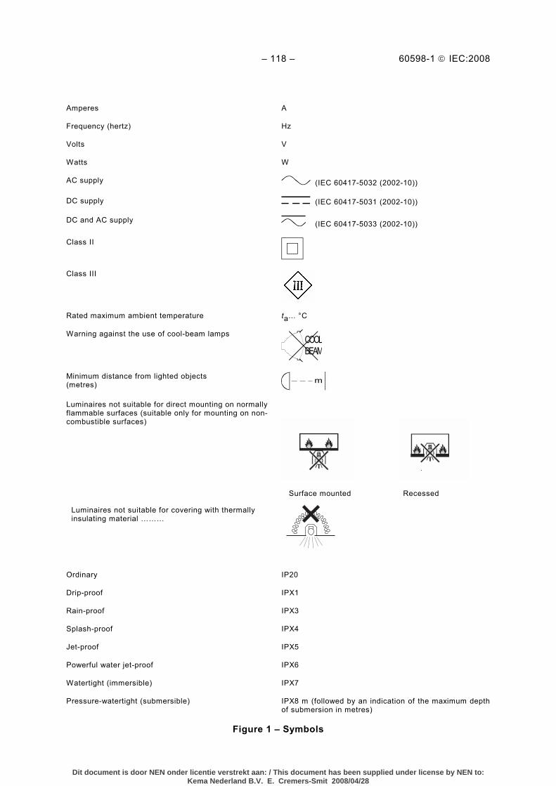
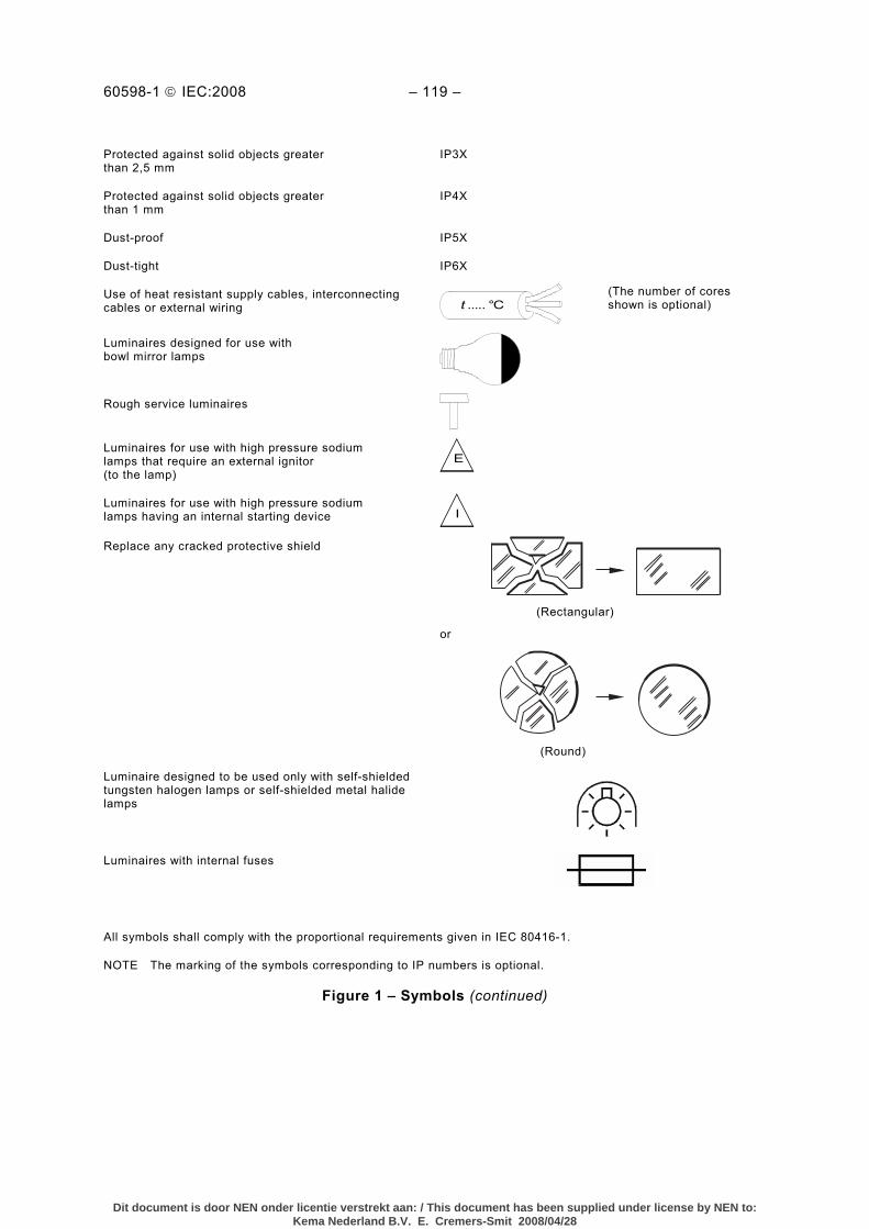
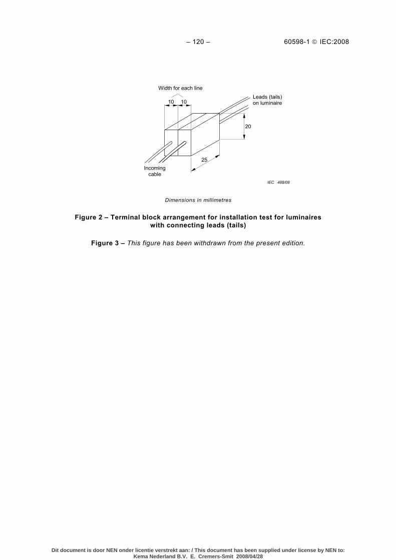
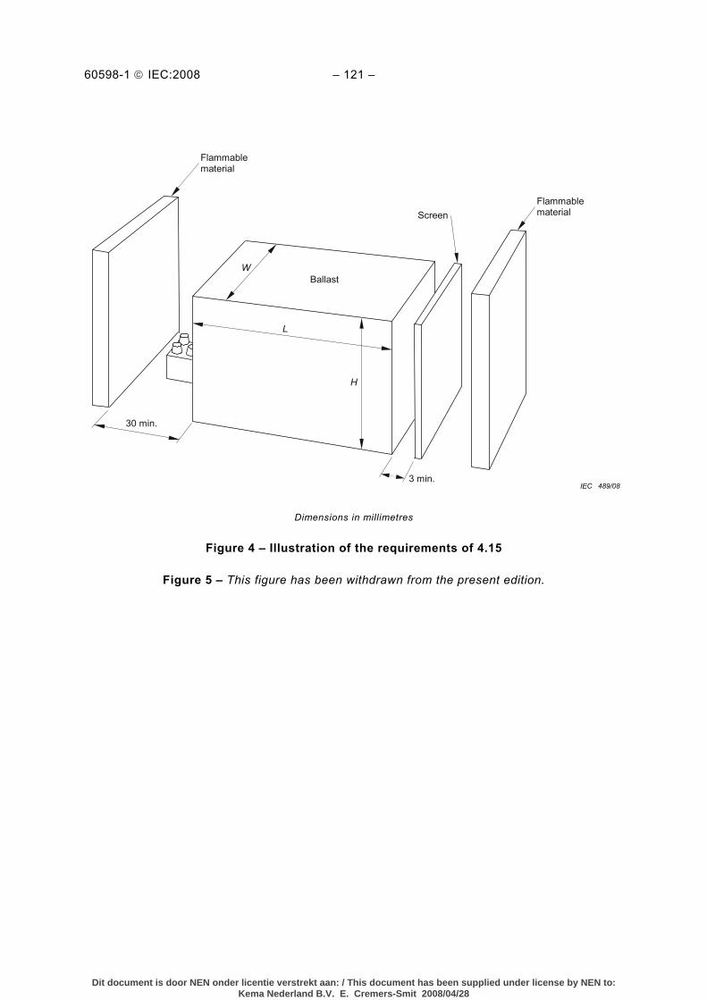
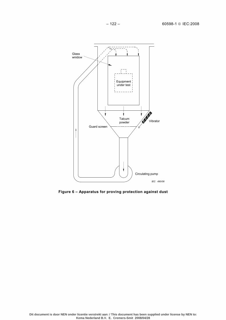
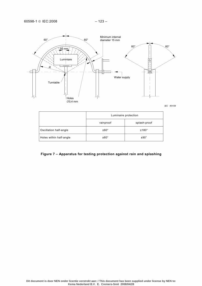
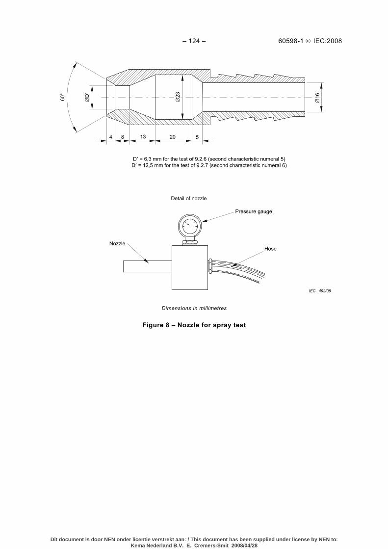
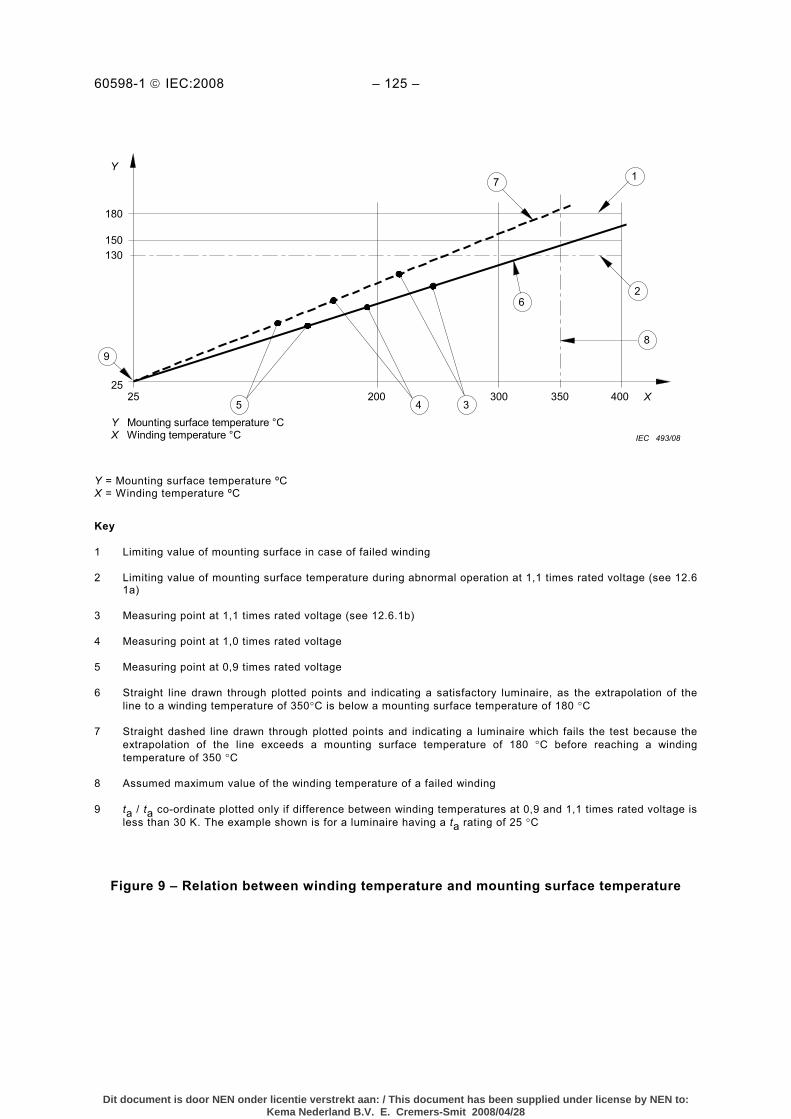
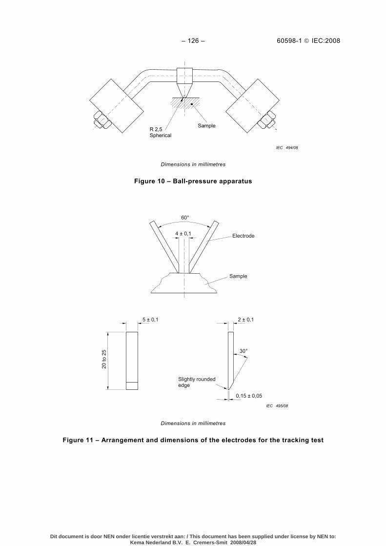
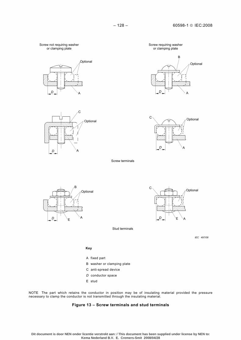
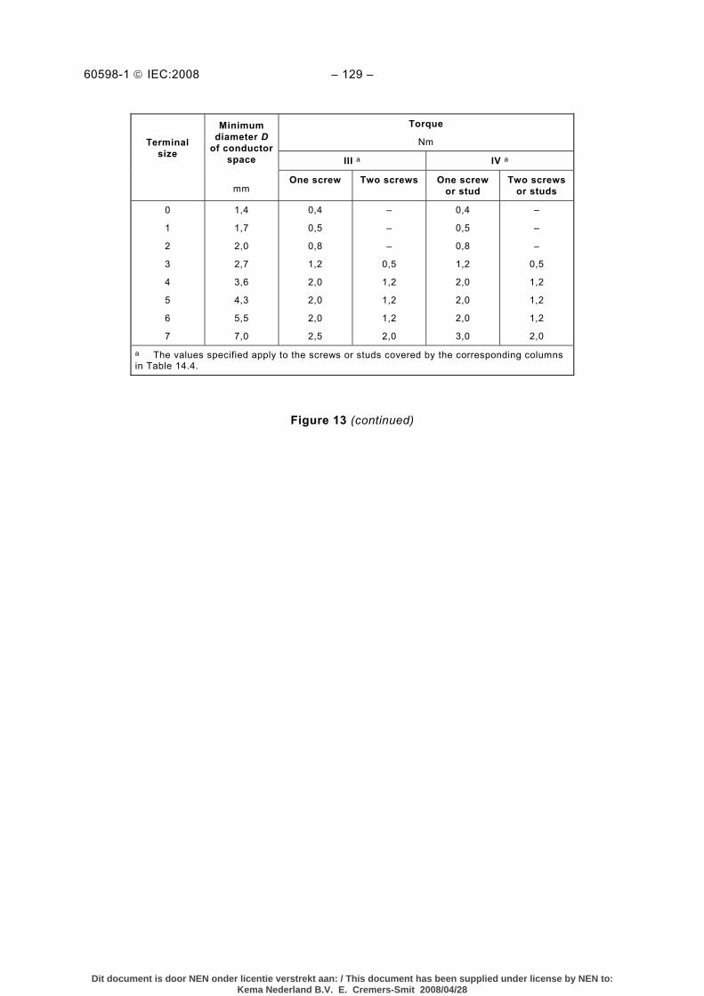
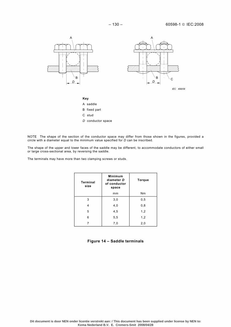
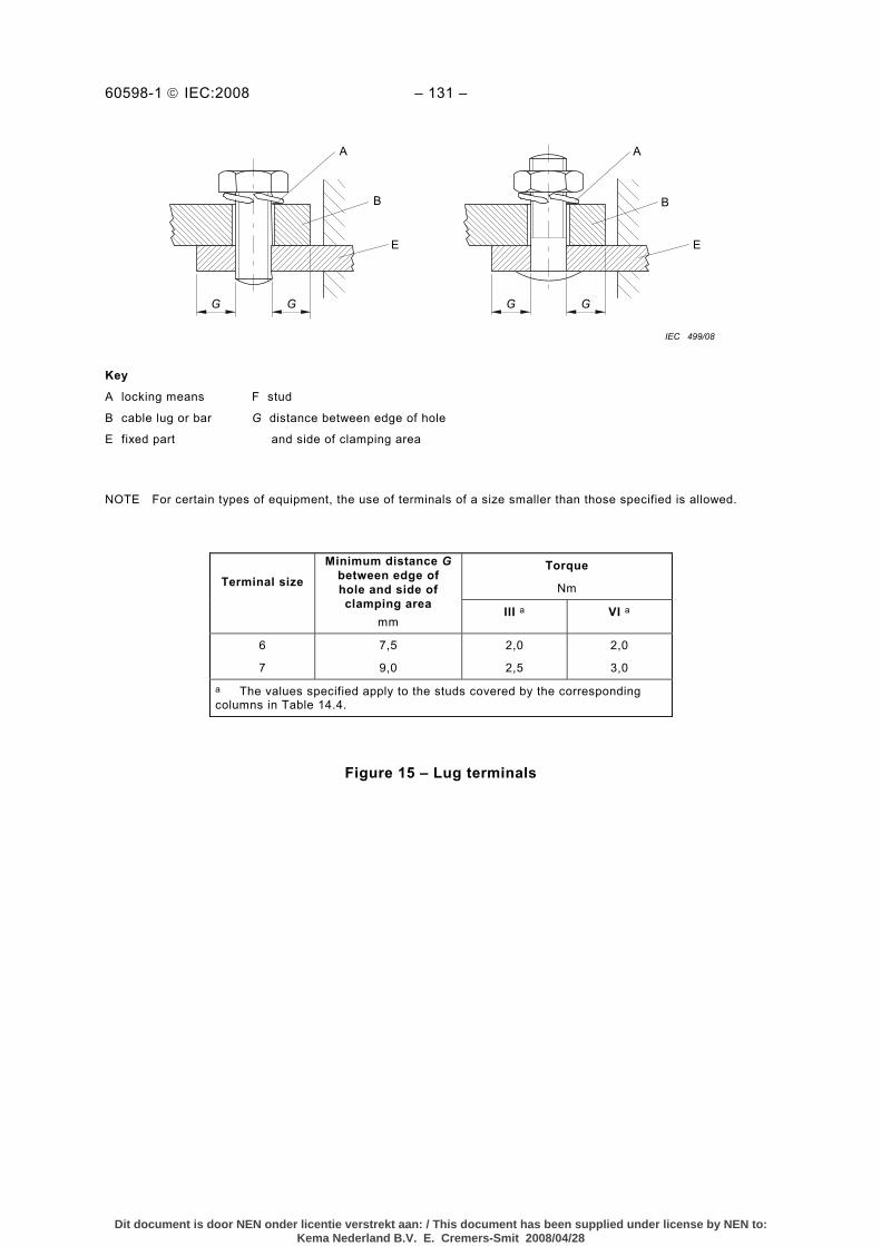
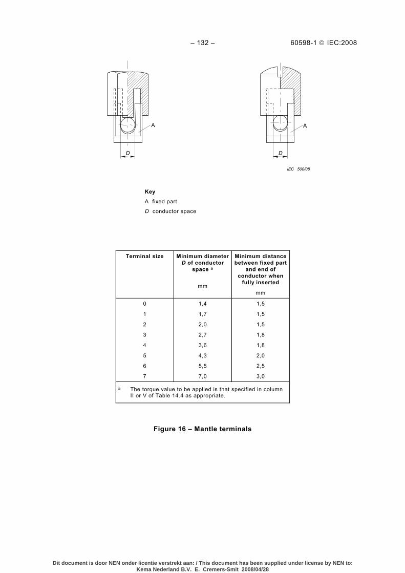
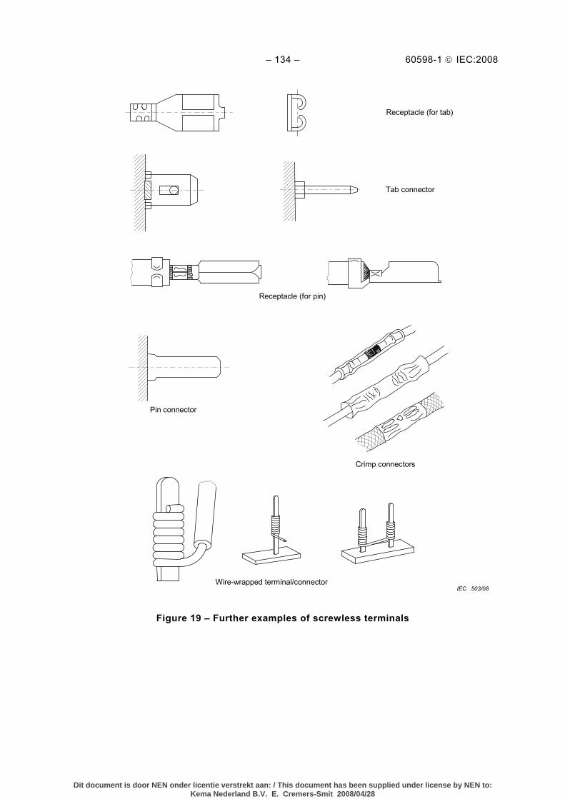
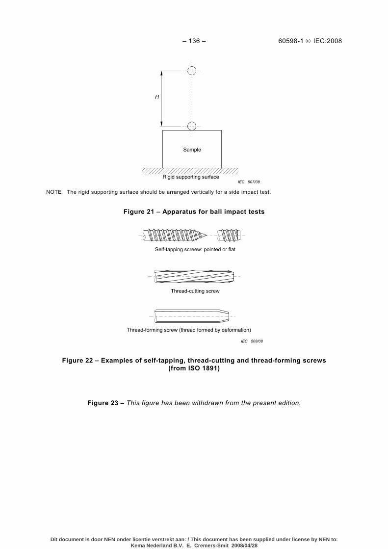
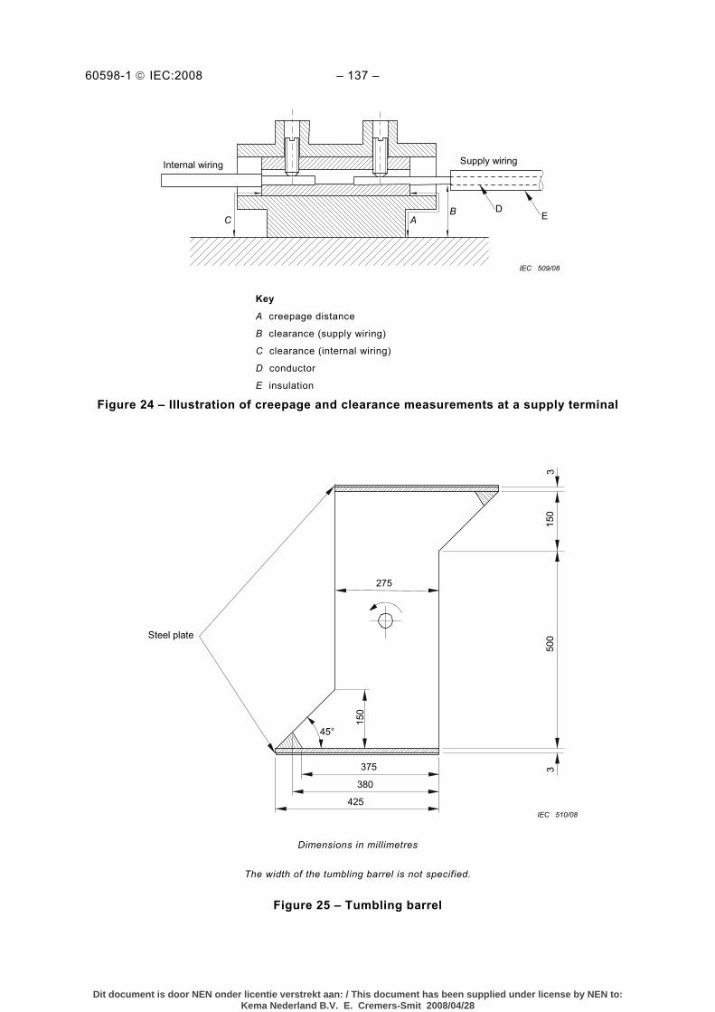
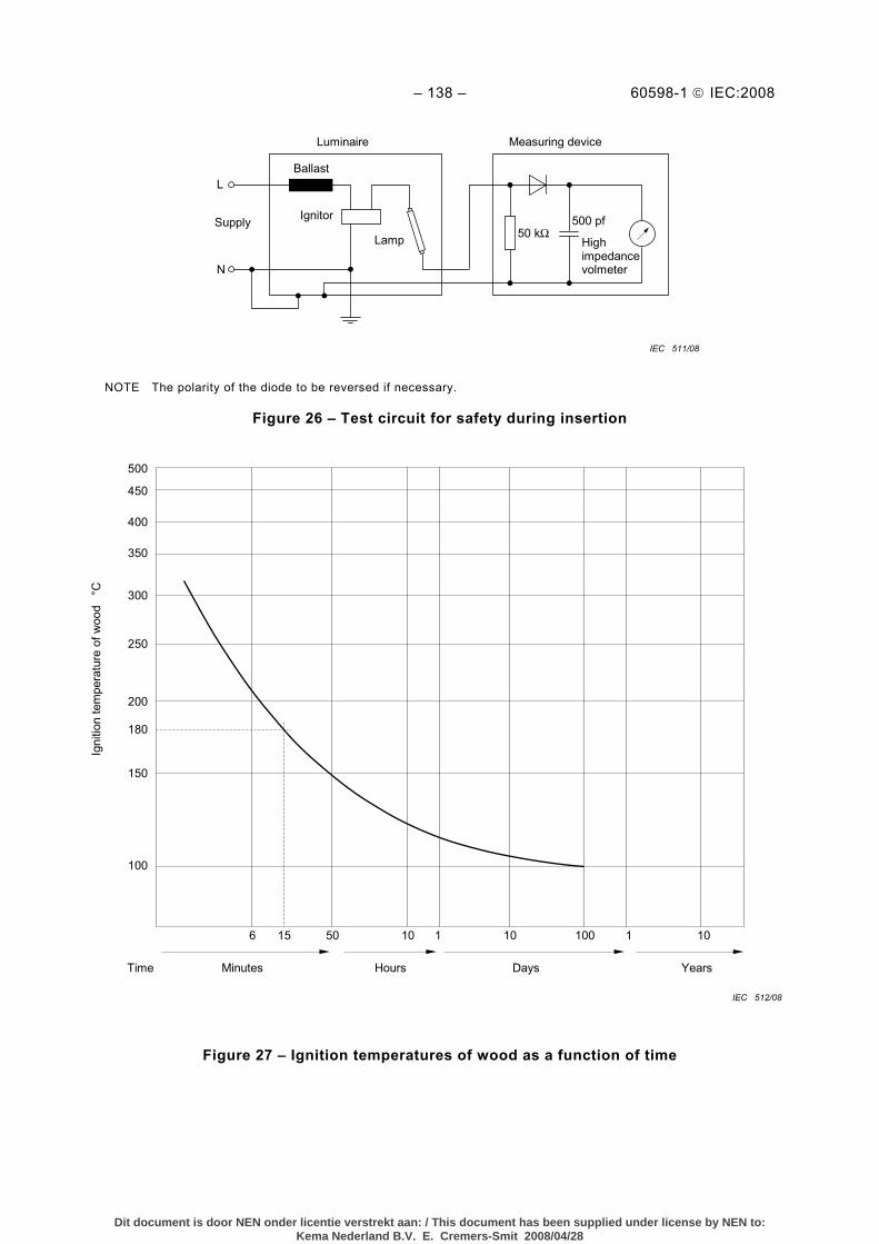
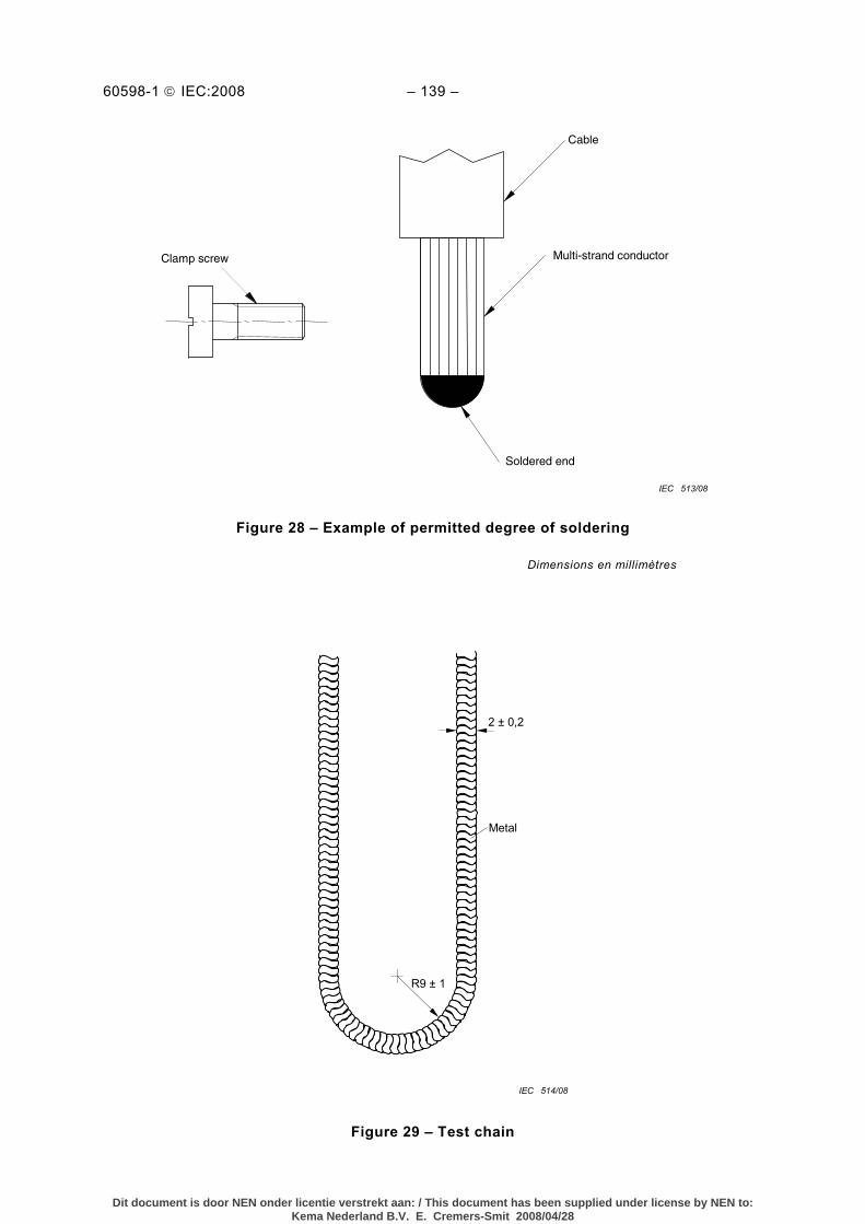
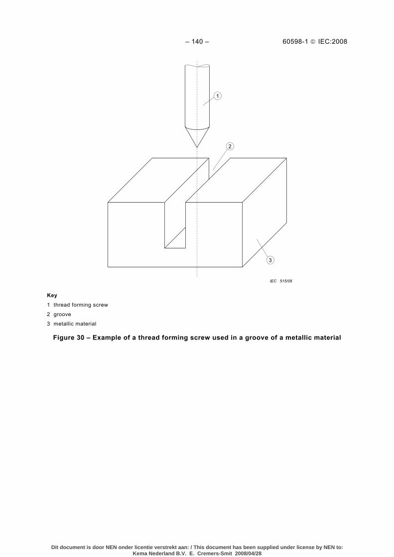
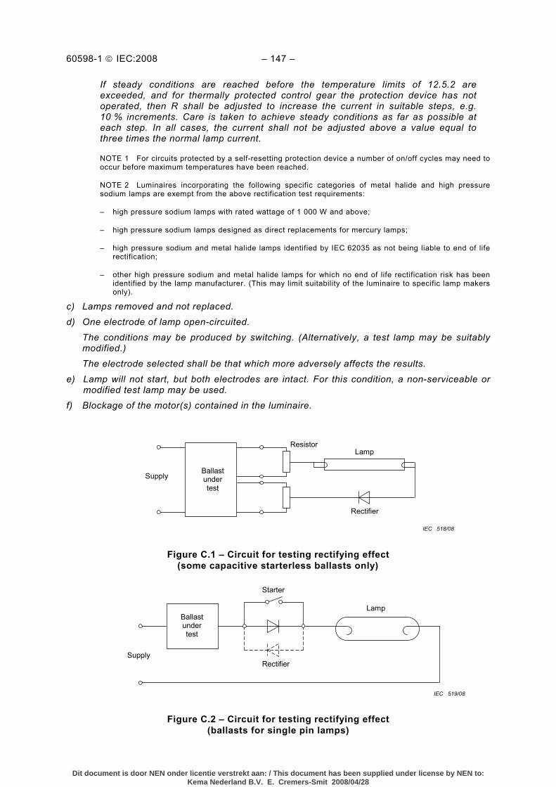
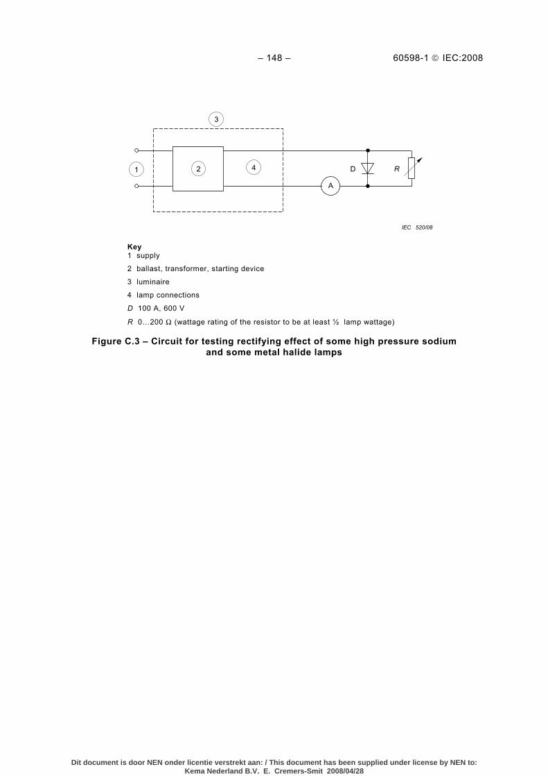
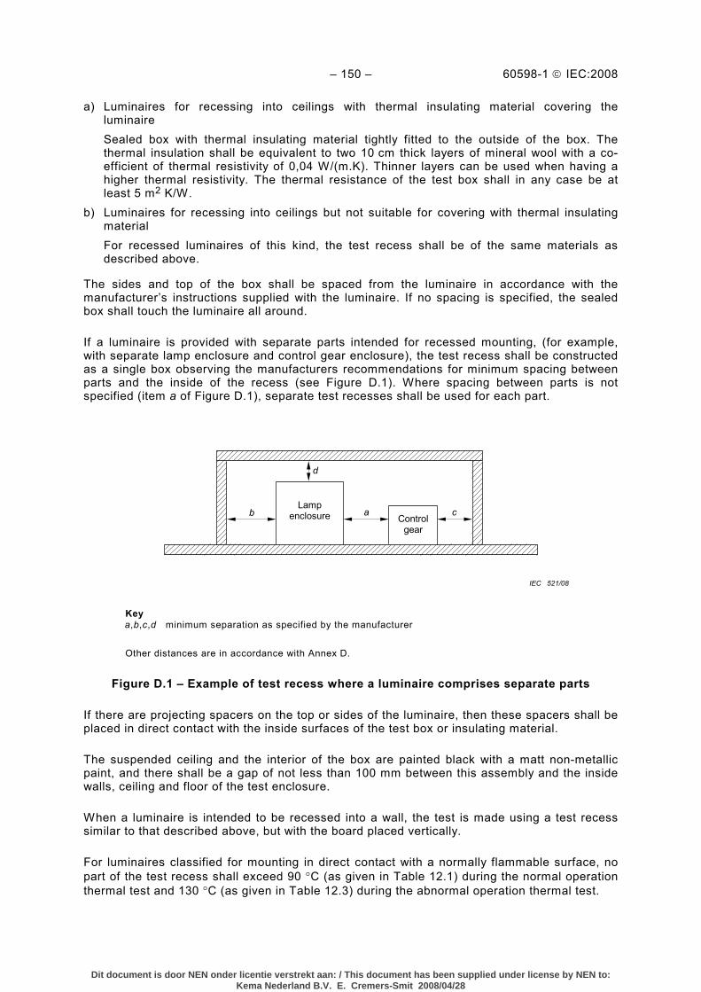
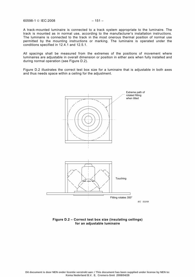
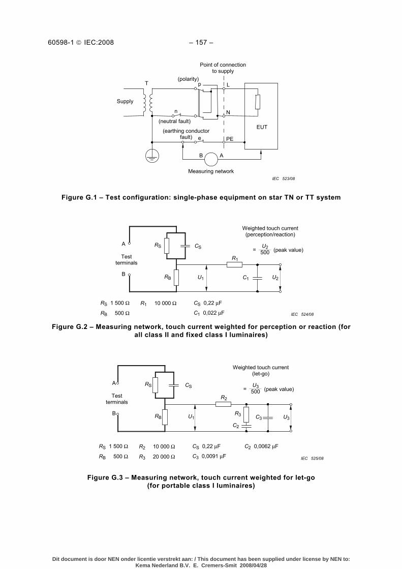
Figure 1 – Symbols ............................................................................................................. 118 Figure 2 – Terminal block arrangement for installation test for luminaires with connecting leads (tails) ....................................................................................................... 120 Figure 3 – This figure has been withdrawn from the present edition. .................................... 120 Figure 4 – Illustration of the requirements of 4.15 ................................................................ 121 Figure 5 – This figure has been withdrawn from the present edition. .................................... 121 Figure 6 – Apparatus for proving protection against dust...................................................... 122 Figure 7 – Apparatus for testing protection against rain and splashing ................................. 123 Figure 8 – Nozzle for spray test ........................................................................................... 124 Figure 9 – Relation between winding temperature and mounting surface temperature .......... 125 Figure 10 – Ball-pressure apparatus .................................................................................... 126 Figure 11 – Arrangement and dimensions of the electrodes for the tracking test .................. 126 Figure 12 – Pillar terminals.................................................................................................. 127 Figure 13 – Screw terminals and stud terminals ................................................................... 128 Figure 14 – Saddle terminals ............................................................................................... 130 Figure 15 – Lug terminals.................................................................................................... 131 Figure 16 – Mantle terminals ............................................................................................... 132 Figure 17 – Construction of electrical connections ............................................................... 133 Figure 18 – Examples of spring-type screwless terminals .................................................... 133 Figure 19 – Further examples of screwless terminals........................................................... 134 Figure 20 – Illustration of the terms “lopping-in” and “through wiring” ................................... 135 Figure 21 – Apparatus for ball impact tests .......................................................................... 136 Figure 22 – Examples of self-tapping, thread-cutting and thread-forming screws (from ISO 1891) ........................................................................................................................... 136 Figure 23 – This figure has been withdrawn from the present edition.................................... 136 Figure 24 – Illustration of creepage and clearance measurements at a supply terminal ........ 137 Figure 25 – Tumbling barrel ................................................................................................ 137 Figure 26 – Test circuit for safety during insertion................................................................ 138 Figure 27 – Ignition temperatures of wood as a function of time ........................................... 138 Figure 28 – Example of permitted degree of soldering ......................................................... 139 Figure 29 – Test chain ........................................................................................................ 139 Figure 30 – Example of a thread forming screw used in a groove of a metallic material ........ 140 Figure 31 – Electro-mechanical contact system with plug/socket connection ........................ 141 Figure 32 – Test circuit for luminaires incorporating fluorescent lamp ≤ 70 W ...................... 141 Figure C.1 – Circuit for testing rectifying effect (some capacitive starterless ballasts only) ... 147 Figure C.2 – Circuit for testing rectifying effect (ballasts for single pin lamps) ...................... 147 Figure C.3 – Circuit for testing rectifying effect of some high pressure sodium and some metal halide lamps..................................................................................................... 148 Figure D.1 – Example of test recess where a luminaire comprises separate parts ................ 150 Figure D.2 – Correct test box size (insulating ceilings) for an adjustable luminaire ............... 151 Figure G.1 – Test configuration: single-phase equipment on star TN or TT system............... 157 Figure G.2 – Measuring network, touch current weighted for perception or reaction (for all class II and fixed class I luminaires)................................................................................ 157 Figure G.3 – Measuring network, touch current weighted for let-go (for portable class I luminaires) .......................................................................................................................... 157
Dit document is door NEN onder licentie verstrekt aan: / This document has been supplied under license by NEN to:Kema Nederland B.V. E. Cremers-Smit 2008/04/28
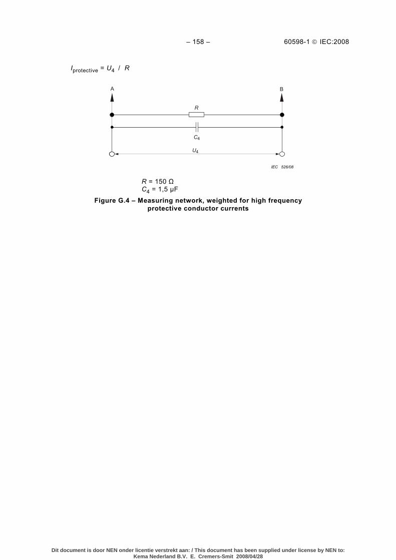
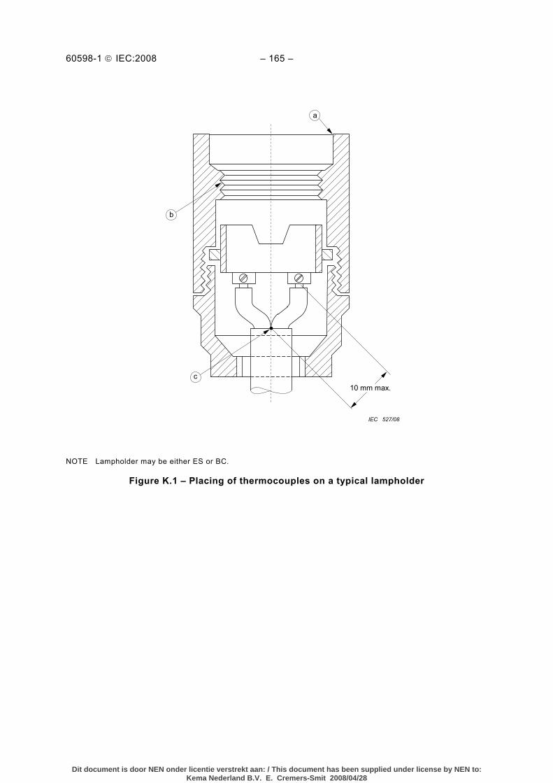
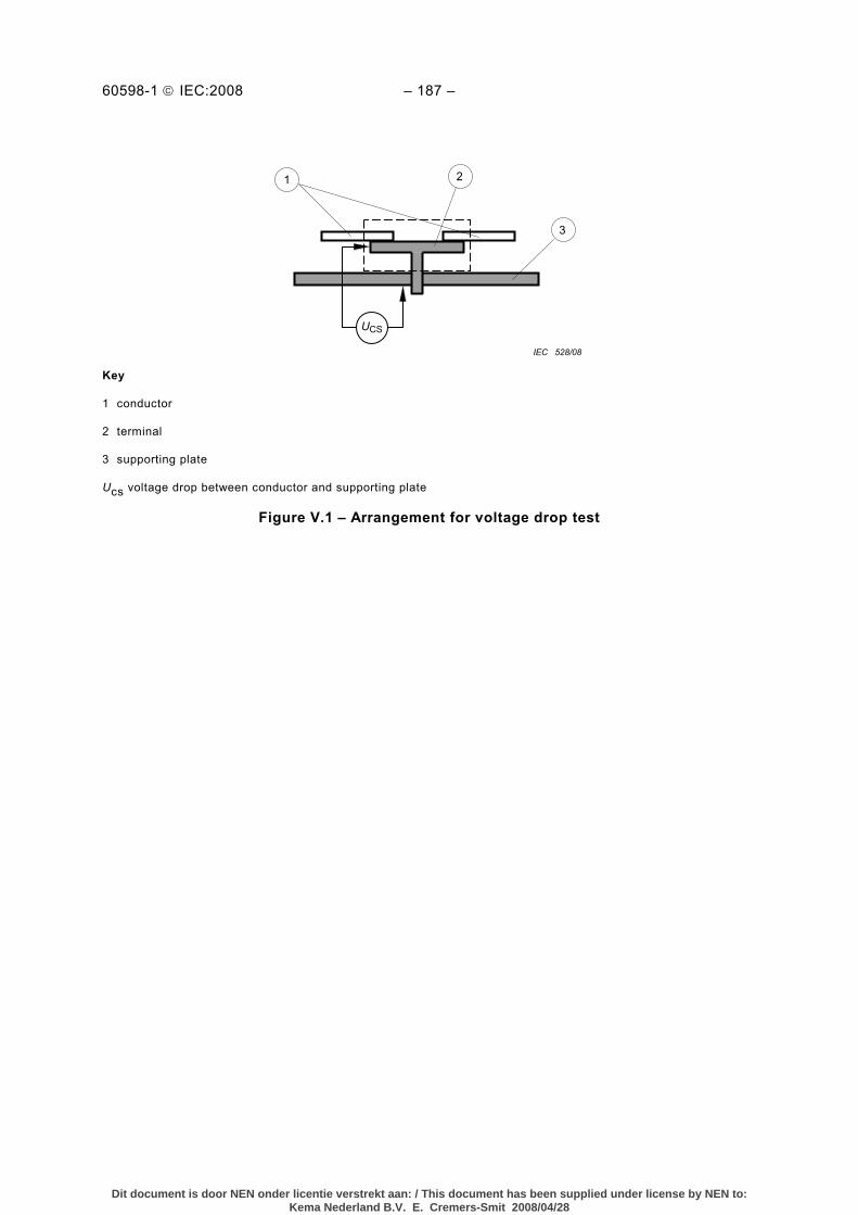
Figure G.4 – Measuring network, weighted for high frequency protective conductor currents .............................................................................................................................. 158 Figure K.1 – Placing of thermocouples on a typical lampholder ............................................ 165 Figure V.1 – Arrangement for voltage drop test.................................................................... 187
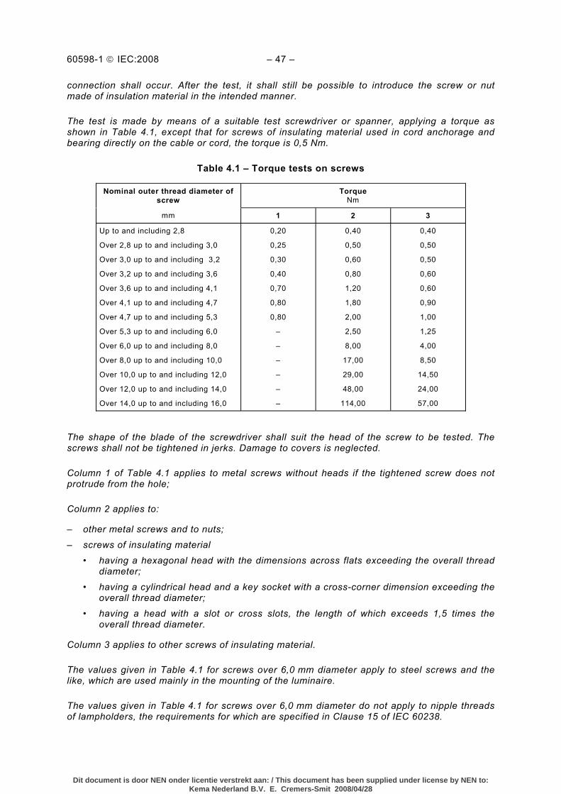
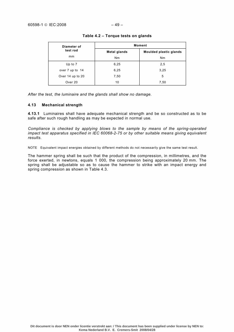
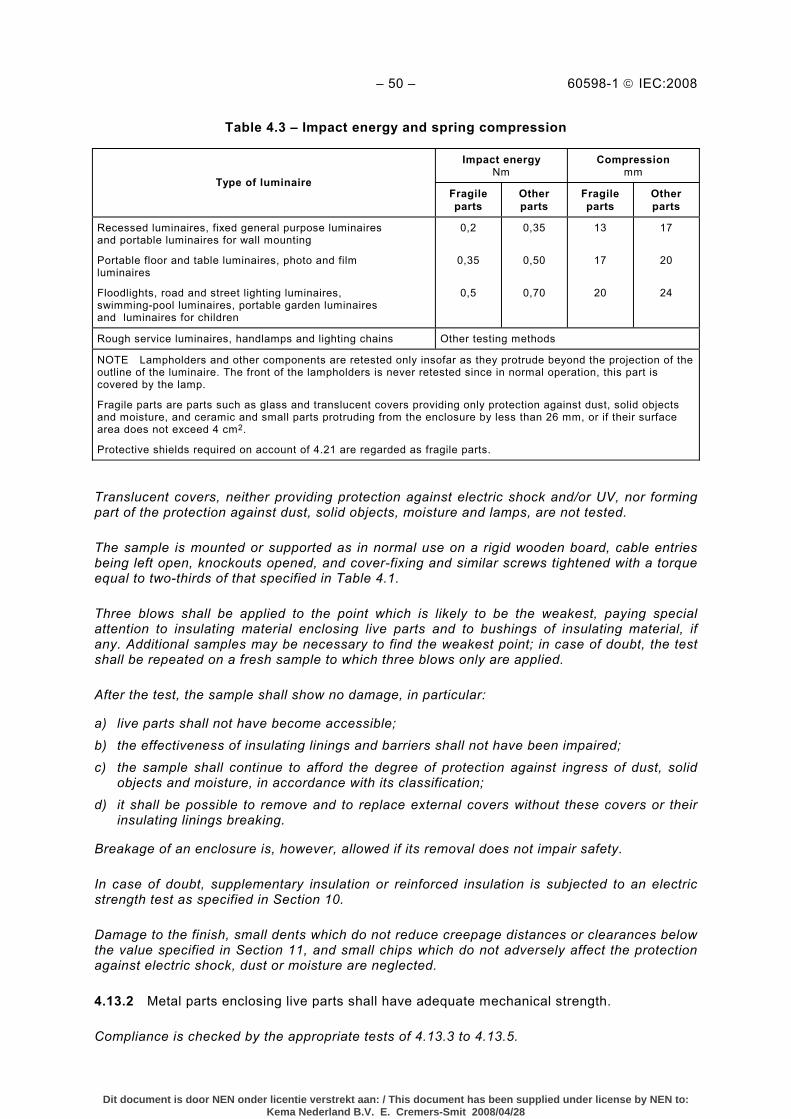
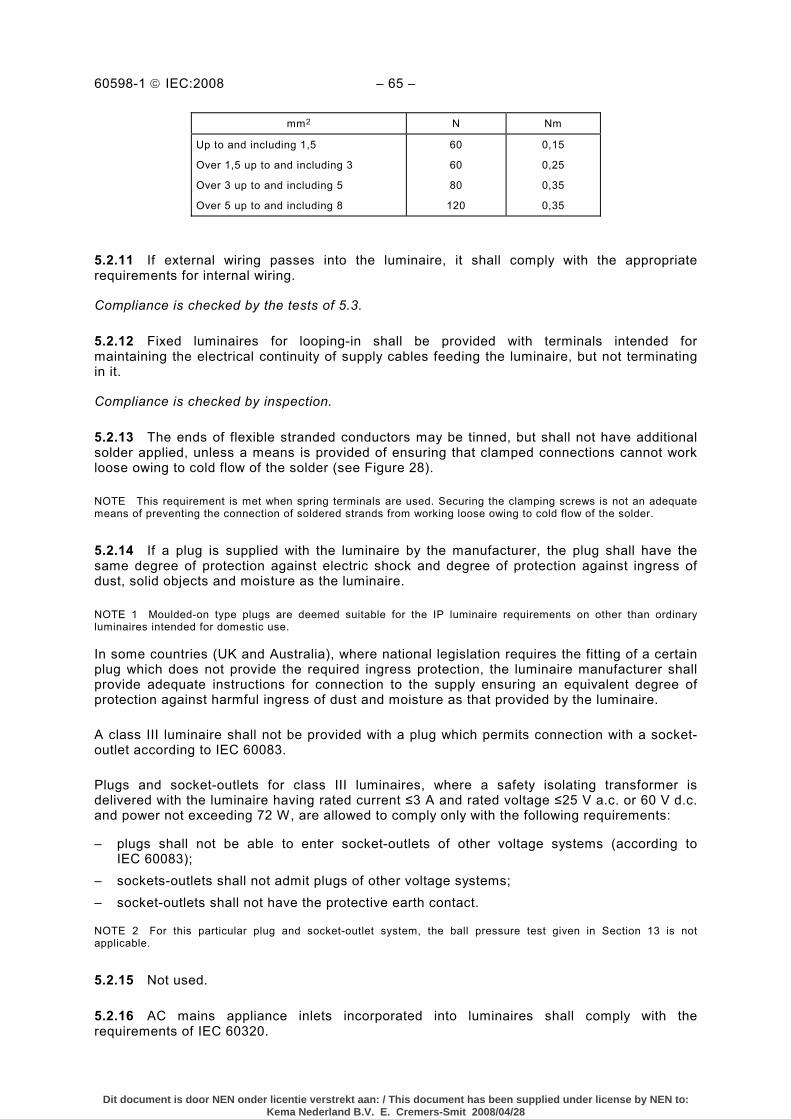
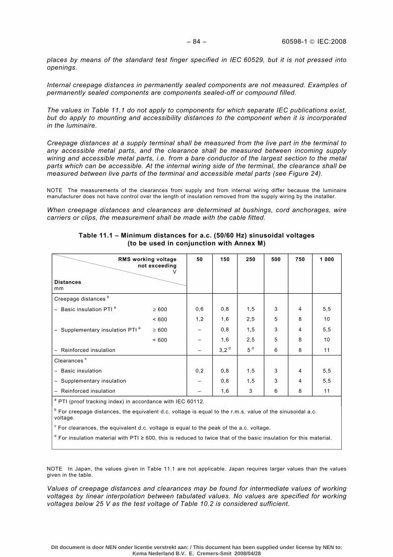
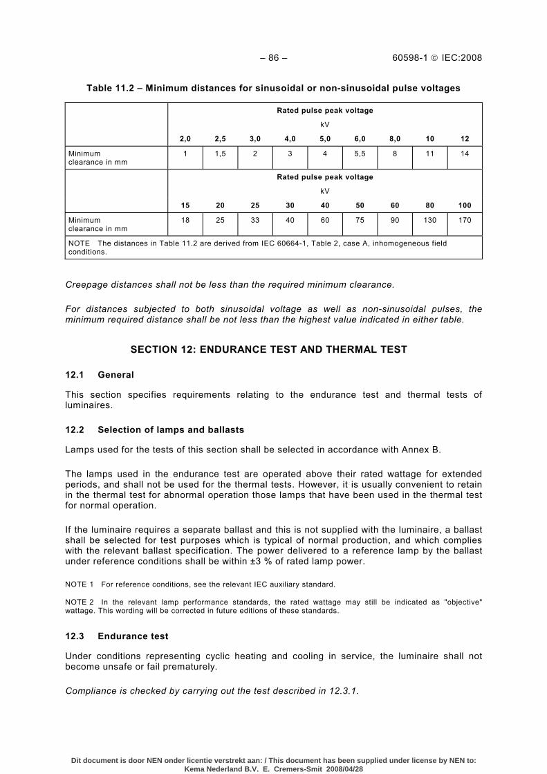
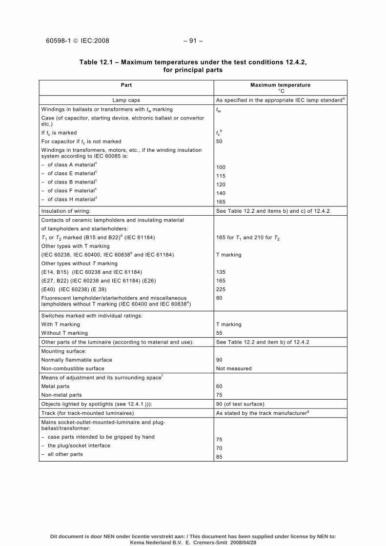
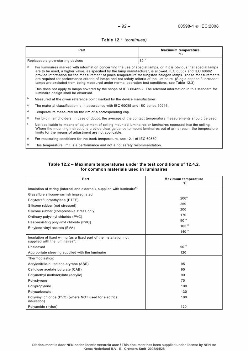
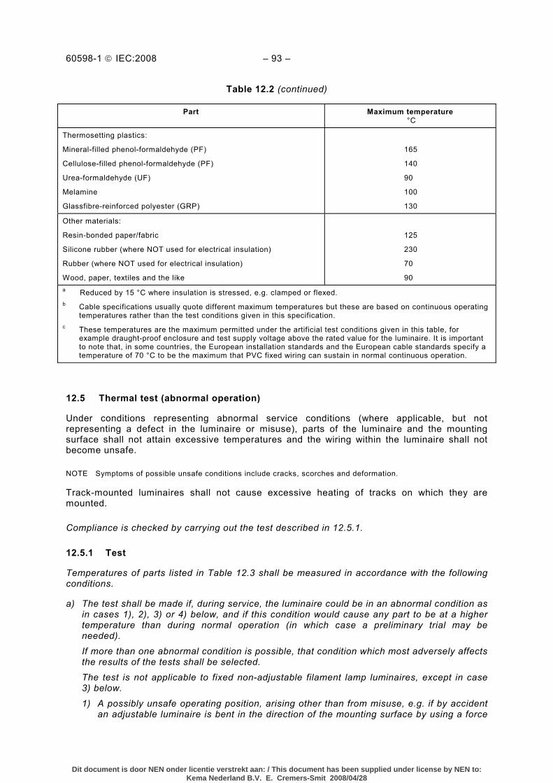
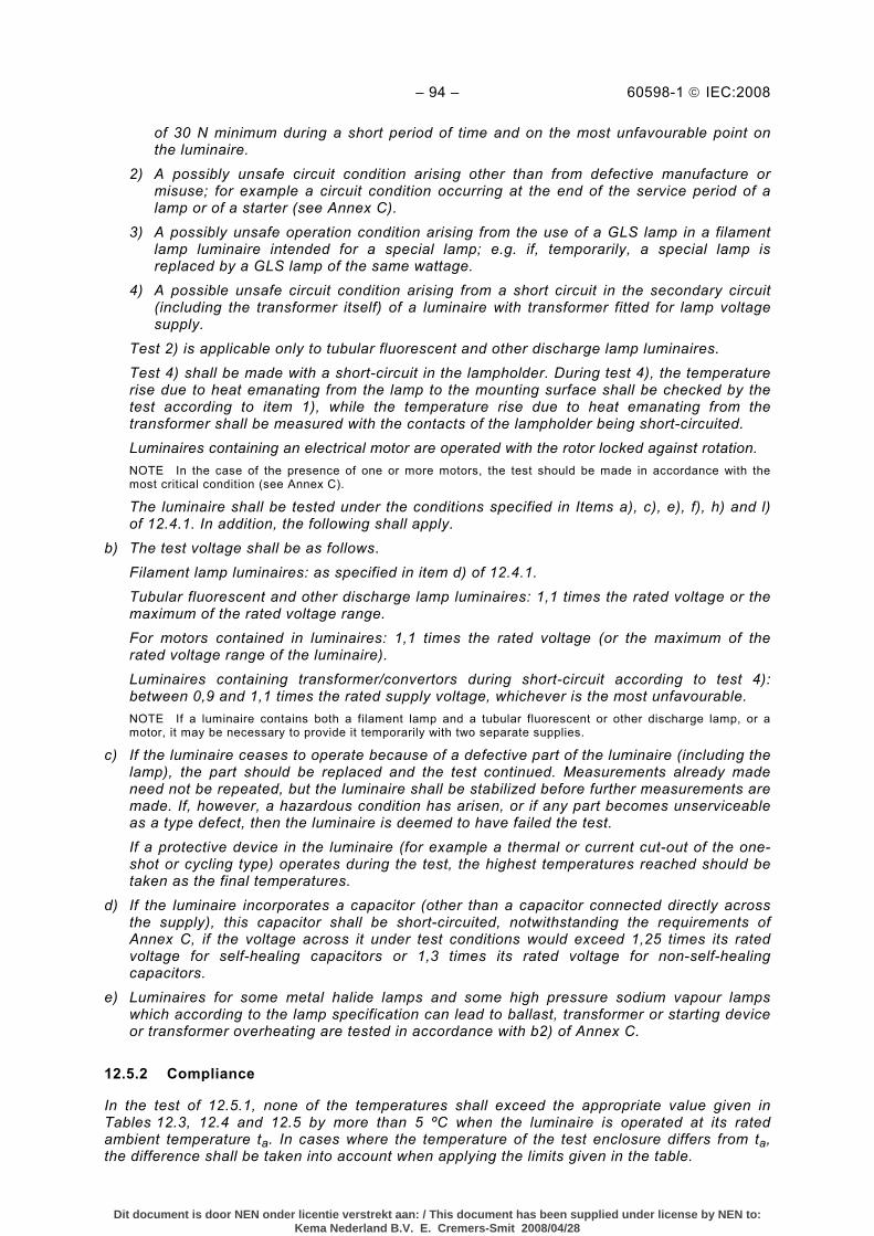
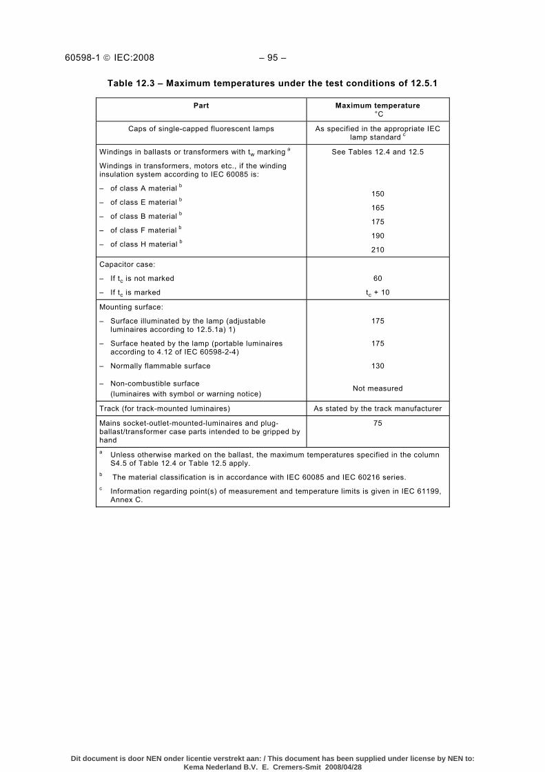
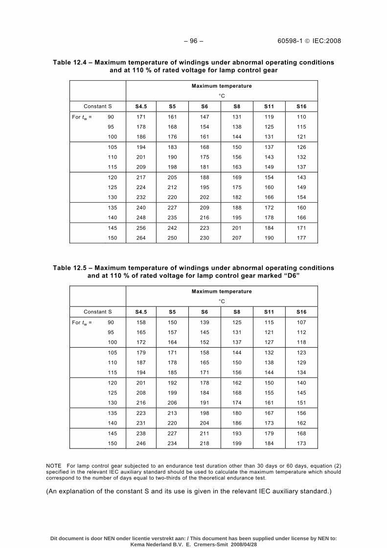
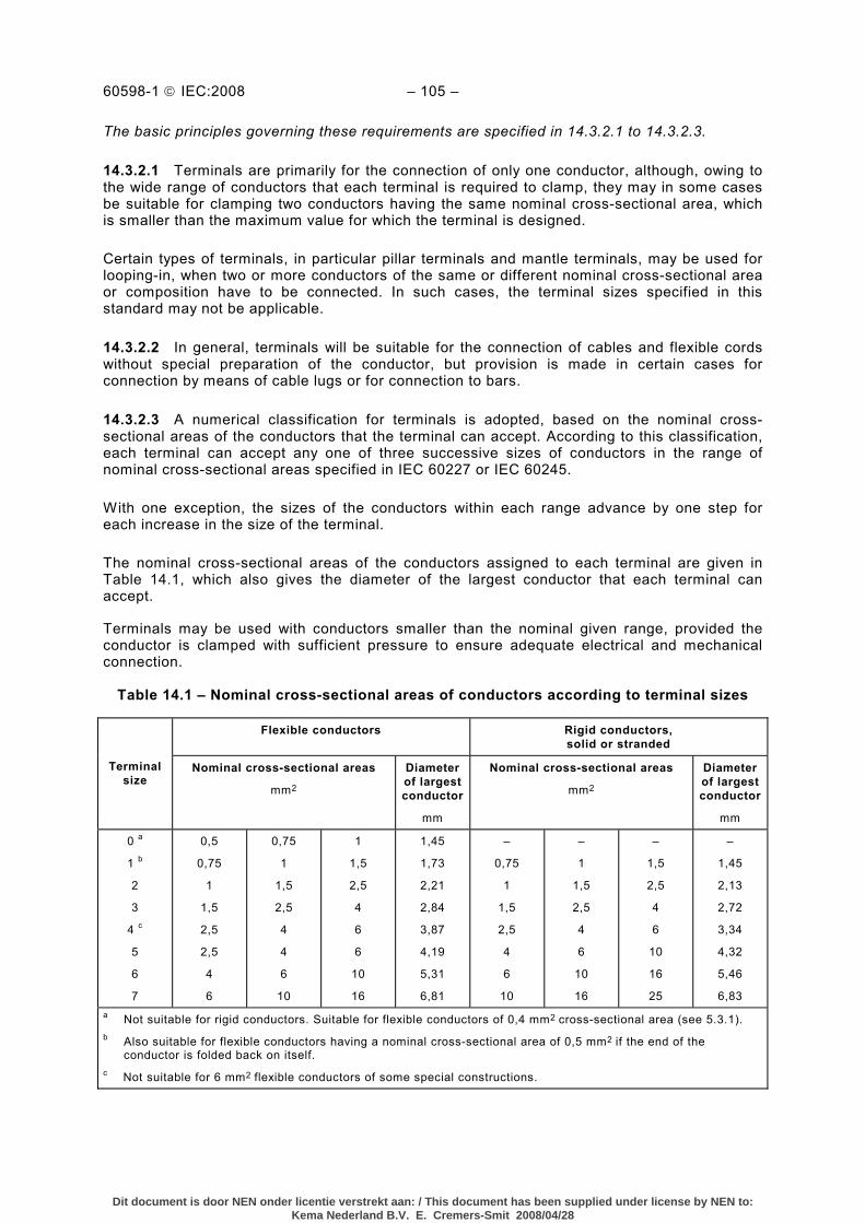
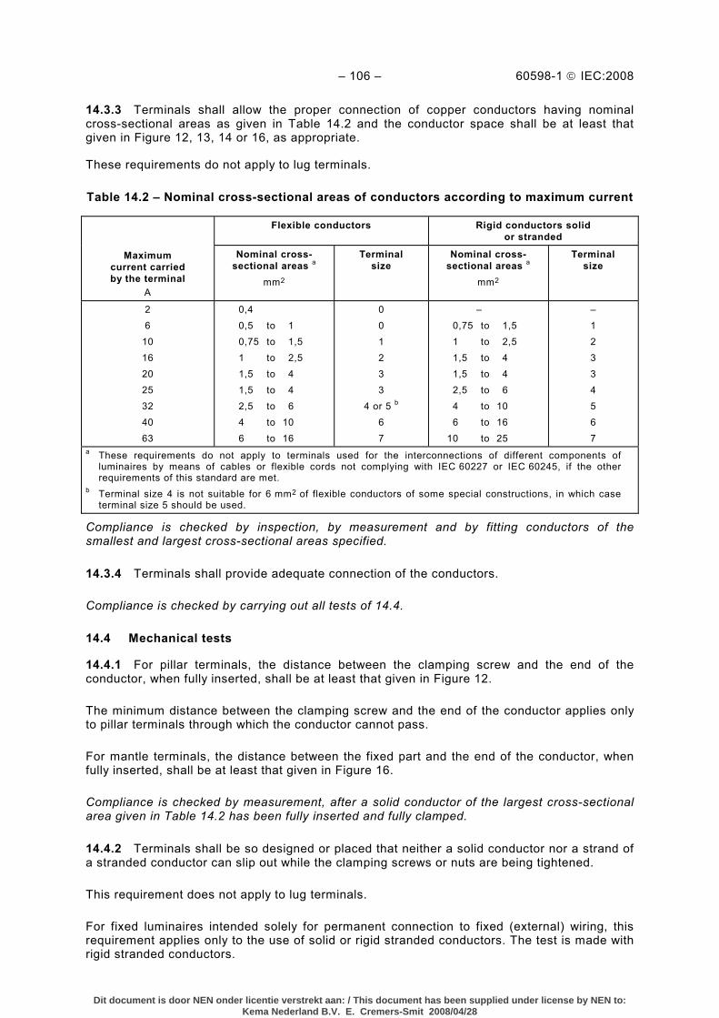
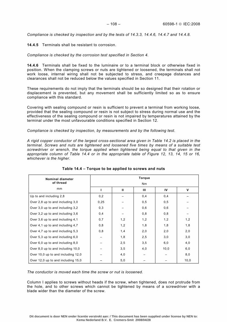
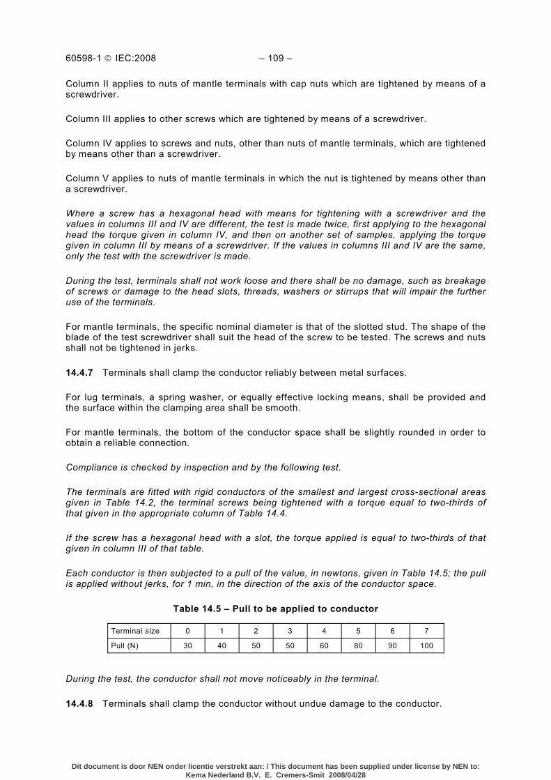
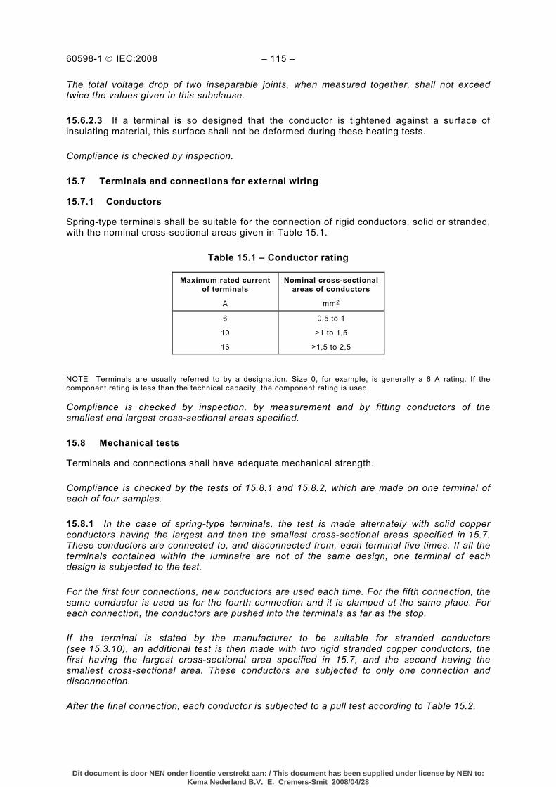
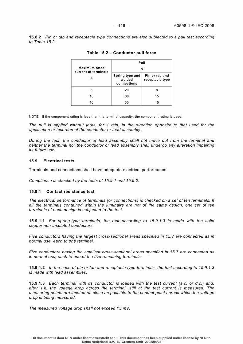
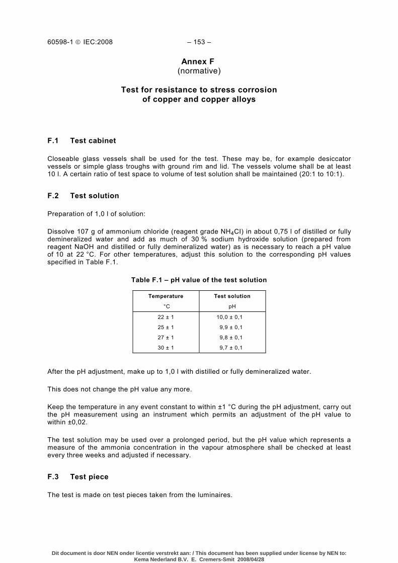
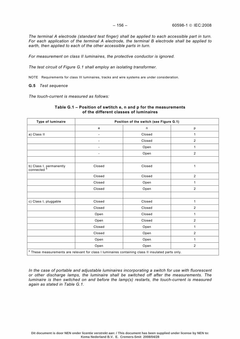
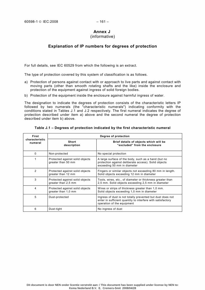
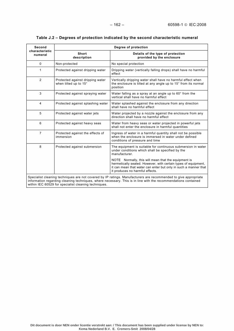
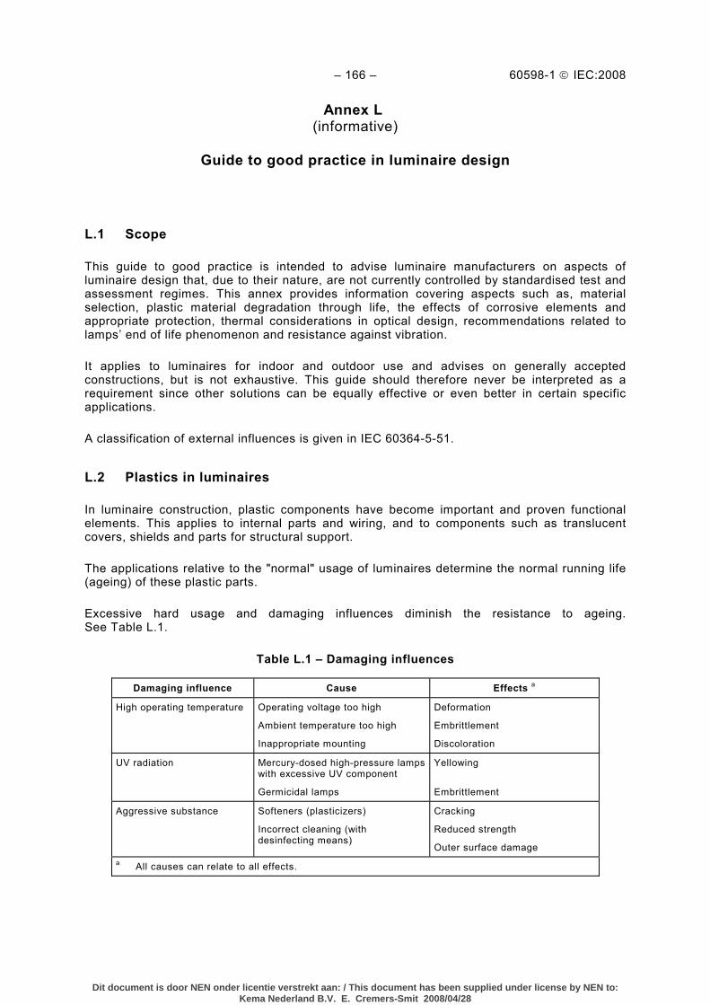
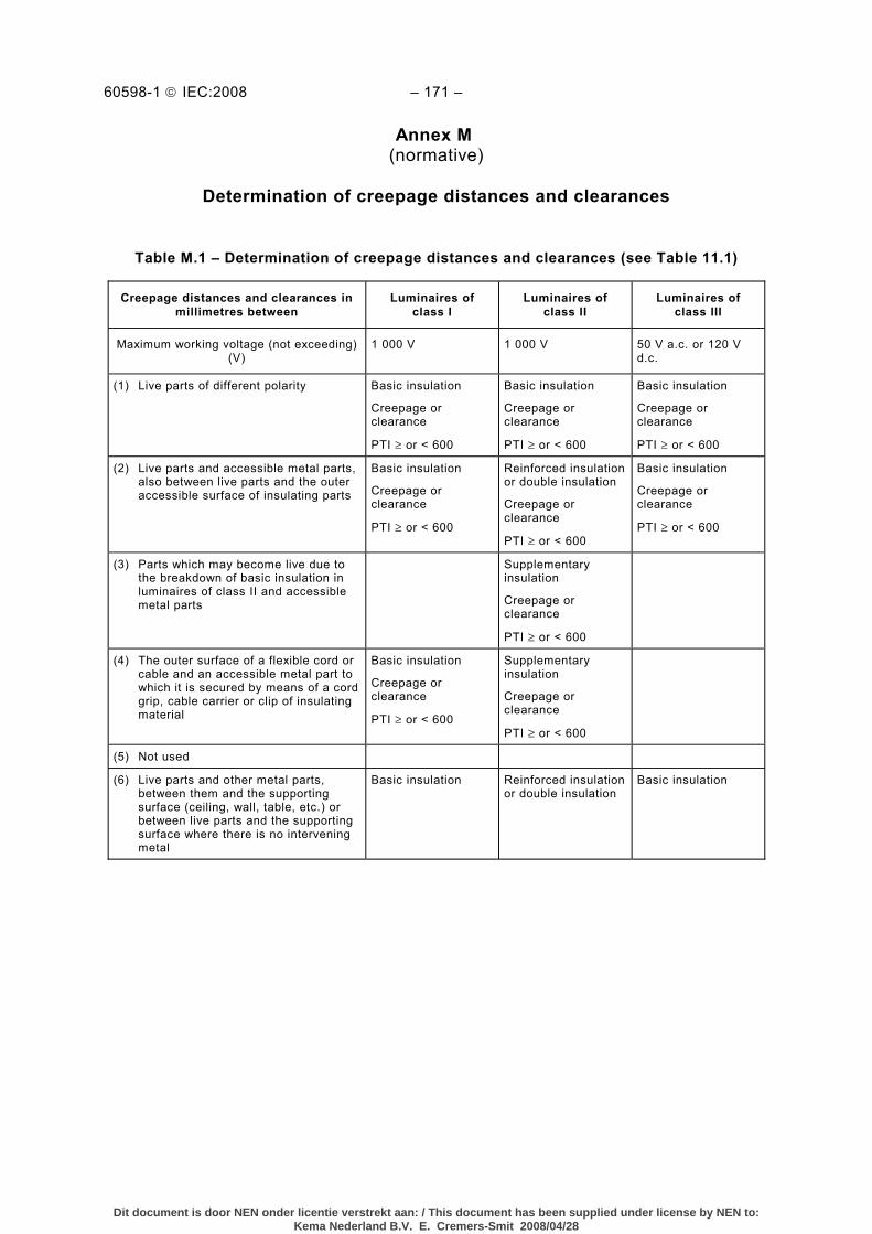
Table 3.1 – Marking .............................................................................................................. 32 Table 4.1 – Torque tests on screws .......................................................................................47 Table 4.2 – Torque tests on glands........................................................................................49 Table 4.3 – Impact energy and spring compression ...............................................................50 Table 4.4 – Test on semi-luminaires ...................................................................................... 53 Table 4.5 – Test on adjusting devices.................................................................................... 54 Table 5.1 – Supply cords .......................................................................................................62 Table 5.2 – Tests for cord anchorage ....................................................................................64 Table 9.1 – Solid-object-proof luminaire test ..........................................................................76 Table 10.1 – Minimum insulation resistance...........................................................................79 Table 10.2 – Electric strength ................................................................................................81 Table 10.3 – Limits of touch current or protective conductor current and electric burn ............ 82 Table 11.1 – Minimum distances for a.c. (50/60 Hz) sinusoidal voltages (to be used in conjunction with Annex M).....................................................................................................84 Table 11.2 – Minimum distances for sinusoidal or non-sinusoidal pulse voltages.................... 86 Table 12.1 – Maximum temperatures under the test conditions 12.4.2, for principal parts ....... 91 Table 12.2 – Maximum temperatures under the test conditions of 12.4.2, for common materials used in luminaires ..................................................................................................92 Table 12.3 – Maximum temperatures under the test conditions of 12.5.1................................ 95 Table 12.4 – Maximum temperature of windings under abnormal operating conditions and at 110 % of rated voltage for lamp control gear ............................................................... 96 Table 12.5 – Maximum temperature of windings under abnormal operating conditions and at 110 % of rated voltage for lamp control gear marked “D6” ........................................... 96 Table 12.6 – Temperature overshoot time limitation...............................................................98 Table 14.1 – Nominal cross-sectional areas of conductors according to terminal sizes ......... 105 Table 14.2 – Nominal cross-sectional areas of conductors according to maximum current ................................................................................................................................ 106 Table 14.3 – Composition of conductors .............................................................................. 107 Table 14.4 – Torque to be applied to screws and nuts ......................................................... 108 Table 14.5 – Pull to be applied to conductor ........................................................................ 109 Table 15.1 – Conductor rating ............................................................................................. 115 Table 15.2 – Conductor pull force ........................................................................................ 116 Table F.1 – pH value of the test solution.............................................................................. 153 Table G.1 – Position of swtitch e, n and p for the measurements of the different classes of luminaires ....................................................................................................................... 156 Table J.1 – Degrees of protection indicated by the first characteristic numeral ..................... 161 Table J.2 – Degrees of protection indicated by the second characteristic numeral ................ 162 Table L.1 – Damaging influences......................................................................................... 166 Table M.1 – Determination of creepage distances and clearances (see Table 11.1) ............. 171
Dit document is door NEN onder licentie verstrekt aan: / This document has been supplied under license by NEN to:Kema Nederland B.V. E. Cremers-Smit 2008/04/28
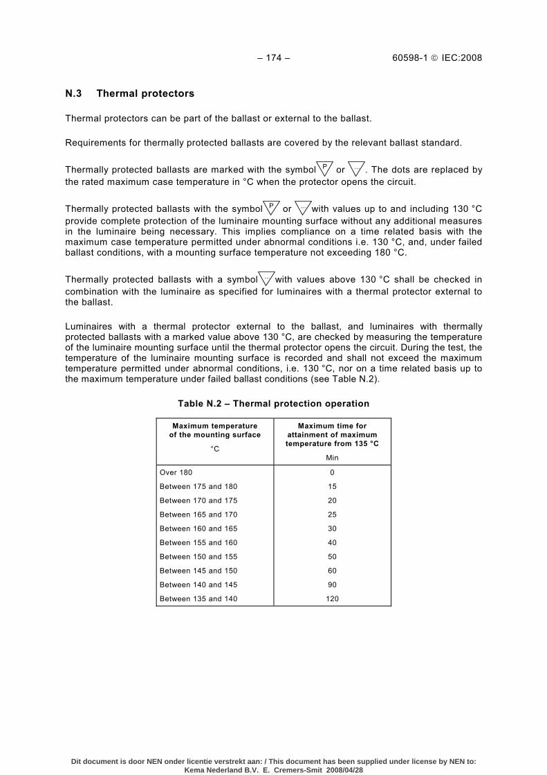
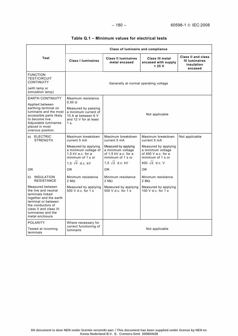
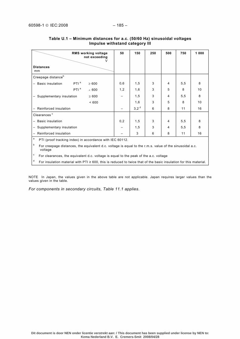
Table N.1 – Guidance on when to use the symbol and its explanation on the luminaire or in the manufacturer’s instructions provided with the luminaire .......................................... 172 Table N.2 – Thermal protection operation ............................................................................ 174 Table Q.1 – Minimum values for electrical tests ................................................................... 180 Table U.1 – Minimum distances for a.c. (50/60 Hz) sinusoidal voltages Impulse withstand category III .......................................................................................................... 185
Dit document is door NEN onder licentie verstrekt aan: / This document has been supplied under license by NEN to:Kema Nederland B.V. E. Cremers-Smit 2008/04/28
INTERNATIONAL ELECTROTECHNICAL COMMISSION ____________
LUMINAIRES –
Part 1: General requirements and tests
FOREWORD
1) The International Electrotechnical Commission (IEC) is a worldwide organization for standardization comprising all national electrotechnical committees (IEC National Committees). The object of IEC is to promote international co-operation on all questions concerning standardization in the electrical and electronic fields. To this end and in addition to other activities, IEC publishes International Standards, Technical Specifications, Technical Reports, Publicly Available Specifications (PAS) and Guides (hereafter referred to as “IEC Publication(s)”). Their preparation is entrusted to technical committees; any IEC National Committee interested in the subject dealt with may participate in this preparatory work. International, governmental and non-governmental organizations liaising with the IEC also participate in this preparation. IEC collaborates closely with the International Organization for Standardization (ISO) in accordance with conditions determined by agreement between the two organizations.
2) The formal decisions or agreements of IEC on technical matters express, as nearly as possible, an international consensus of opinion on the relevant subjects since each technical committee has representation from all interested IEC National Committees.
3) IEC Publications have the form of recommendations for international use and are accepted by IEC National Committees in that sense. While all reasonable efforts are made to ensure that the technical content of IEC Publications is accurate, IEC cannot be held responsible for the way in which they are used or for any misinterpretation by any end user.
4) In order to promote international uniformity, IEC National Committees undertake to apply IEC Publications transparently to the maximum extent possible in their national and regional publications. Any divergence between any IEC Publication and the corresponding national or regional publication shall be clearly indicated in the latter.
5) IEC provides no marking procedure to indicate its approval and cannot be rendered responsible for any equipment declared to be in conformity with an IEC Publication.
6) All users should ensure that they have the latest edition of this publication.
7) No liability shall attach to IEC or its directors, employees, servants or agents including individual experts and members of its technical committees and IEC National Committees for any personal injury, property damage or other damage of any nature whatsoever, whether direct or indirect, or for costs (including legal fees) and expenses arising out of the publication, use of, or reliance upon, this IEC Publication or any other IEC Publications.
8) Attention is drawn to the Normative references cited in this publication. Use of the referenced publications is indispensable for the correct application of this publication.
9) Attention is drawn to the possibility that some of the elements of this IEC Publication may be the subject of patent rights. IEC shall not be held responsible for identifying any or all such patent rights.
International Standard IEC 60598-1 has been prepared by subcommittee 34D: Luminaires, of IEC technical committee 34: Lamps and related equipment.
This seventh edition cancels and replaces the sixth edition published in 2003. It constitutes a technical revision. The major changes which may affect certification are given in Annex R.
Annex R shows where a new text has been included which contains more serious/critical requirements requiring products to be re-tested.
The text of this standard is based on the following documents:
FDIS Report on voting
34D/889/FDIS 34D/895/RVD
Full information on the voting for the approval of this standard can be found in the report on voting indicated in the above table.
Dit document is door NEN onder licentie verstrekt aan: / This document has been supplied under license by NEN to:Kema Nederland B.V. E. Cremers-Smit 2008/04/28
NOTE In this standard, the following print types are used:
– requirements: in roman type; – test specifications: in italic type;
– notes: in small roman type.
A list of all parts of the IEC 60598 series, under the general title: Luminaires, can be found on the IEC website.
The committee has decided that the contents of this publication will remain unchanged until the maintenance result date indicated on the IEC web site under "http://webstore.iec.ch" in the data related to the specific publication. At this date, the publication will be
• reconfirmed, • withdrawn, • replaced by a revised edition, or • amended.
Dit document is door NEN onder licentie verstrekt aan: / This document has been supplied under license by NEN to:Kema Nederland B.V. E. Cremers-Smit 2008/04/28
This Part 1 of International Standard IEC 60598 specifies general requirements for luminaires, incorporating electric light sources for operation from supply voltages up to 1 000 V. The requirements and related tests of this standard cover: classification, marking, mechanical construction and electrical construction.
Each section of this Part 1 is read in conjunction with this Section 0 and with other relevant sections to which reference is made.
Each part of IEC 60598-2 details requirements for a particular type of luminaire or group of luminaires on supply voltages not exceeding 1 000 V. These parts are published separately for ease of revision and additional sections will be added as and when a need for them is recognized.
Attention is drawn to the fact that this Part 1 covers all aspects of safety (electrical, thermal and mechanical).
The presentation of photometric data for luminaires is under consideration by the International Commission on Illumination (CIE) and is not, therefore, included in this Part 1.
Requirements are included in this Part 1 for luminaires incorporating ignitors with nominal peak values of the voltage pulse not exceeding those of Table 11.2. The requirements apply to luminaires with ignitors built into ballasts and to luminaires with ignitors separate from ballasts. For luminaires with ignitors built into lamps, the requirements are under consideration.
Requirements for semi-luminaires are included in this Part 1.
In general, this Part 1 covers safety requirements for luminaires. The object of this Part 1 is to provide a set of requirements and tests which are considered to be generally applicable to most types of luminaires and which can be called up as required by the detail specifications of IEC 60598-2. This Part 1 is thus not regarded as a specification in itself for any type of luminaire, and its provisions apply only to particular types of luminaires to the extent determined by the appropriate part of IEC 60598-2.
The parts of IEC 60598-2, in making reference to any of the sections of Part 1, specify the extent to which that section is applicable and the order in which the tests are to be performed; they also include additional requirements as necessary.
The order in which the sections of Part 1 are numbered has no particular significance as the order in which their provisions apply is determined for each type of luminaire or group of luminaires by the appropriate part of IEC 60598-2. All parts of IEC 60598-2 are self-contained and therefore do not contain references to other parts of IEC 60598-2.
Dit document is door NEN onder licentie verstrekt aan: / This document has been supplied under license by NEN to:Kema Nederland B.V. E. Cremers-Smit 2008/04/28
Where the requirements of any of the sections of Part 1 are referred to in the parts of IEC 60598-2 by the phrase "The requirements of section... of IEC 60598-1 apply", this phrase is to be interpreted as meaning that all the requirements of that section of Part 1 apply except those which are clearly inapplicable to the particular type of luminaire covered by that part of IEC 60598-2.
For explosion proof luminaires, as covered by IEC 60079, the requirements of IEC 60598 (selecting the appropriate parts 2) are applied in addition to the requirements of IEC 60079. In the event of any conflict between IEC 60598 and IEC 60079, the requirements of IEC 60079 take priority.
Attention is drawn to lamp performance standards which contain “information for luminaire design”; this should be followed for proper lamp operation; however, this standard does not require the testing of lamp performance as part of the type test approval for luminaires.
Improvements in safety to take into account the state of the art technology are incorporated in the standards with revisions and amendments on an ongoing basis. Regional standardisation bodies may include statements in their derived standards to cover products which have complied with the previous document as shown by the manufacturer or standardization body. The statements may require that for such products, the previous standard may continue to apply to production until a defined date after which the new standard shall apply.
0.2 Normative references
The following referenced documents are indispensable for the application of this document. For dated references, only the edition cited applies. For undated references, the latest edition of the referenced document (including any amendments) applies.
IEC 60061, Lamp caps and holders together with gauges for the control of interchangeability and safety
IEC 60061-2, Lamp caps and holders together with gauges for the control of interchangeability and safety – Part 2: Lampholders
IEC 60061-3:2007, Lamp caps and holders together with gauges for the control of interchangeability and safety – Part 3: Gauges
IEC 60065:2001, Audio, video and similar electronic apparatus – Safety requirements
IEC 60068-2-75, Environmental testing – Part 2-75: Tests – Test Eh: Hammer tests
IEC 60079 (all parts), Electrical apparatus for explosive gas atmospheres
IEC 60083, Plugs and socket-outlets for domestic and similar general use standardized in member countries of IEC
IEC 60085, Electrical insulation – Thermal evaluation and designation
IEC 60112:2003, Method for the determination of the proof and the comparative tracking indices of solid insulating materials
IEC 60155, Glow-starters for fluorescent lamps
IEC 60227(all parts), Polyvinyl chloride insulated cables of rated voltages up to and including 450/750 V
IEC 60238:2004, Edison screw lampholders
Dit document is door NEN onder licentie verstrekt aan: / This document has been supplied under license by NEN to:Kema Nederland B.V. E. Cremers-Smit 2008/04/28
IEC 60360, Standard method of measurement of lamp cap temperature rise
IEC 60364-4-41:2005, Low-voltage electrical installations – Part 4-41: Protection for safety – Protection against electric shock
IEC 60384-14, Fixed capacitors for use in electronic equipment – Part 14: Sectional specification: Fixed capacitors for electromagnetic interference suppression and connection to the supply mains
IEC 60400, Lampholders for tubular fluorescent lamps and starterholders
IEC 60417, Graphical symbols for use on equipment
IEC 60432-1:1999, Incandescent lamps – Safety specifications – Part 1: Tungsten filament lamps for domestic and similar general lighting purposes 1) Amendment 1 (2005)
IEC 60432-2:1999, Incandescent lamps – Safety specifications – Part 2: Tungsten halogen lamps for domestic and similar general lighting purposes 2) Amendment 1 (2005)
IEC 60449:1973, Voltage bands for electrical installations of buildings Amendment 1 (1979)
IEC 60529, Degrees of protection provided by enclosures (IP Code)
IEC 60570:2003, Electrical supply track systems for luminaires
IEC 60598-2 (all parts), Luminaires – Part 2: Particular requirements
IEC 60598-2-4:1997, Luminaires – Part 2: Particular requirements – Section 4: Portable general purpose luminaires
IEC 60634, Heat test source (H.T.S.) lamps for carrying out heating tests on luminaires
IEC 60662, High pressure sodium vapour lamps
IEC 60664-1:2007, Insulation coordination for equipment within low-voltage systems – Part 1: Principles, requirements and tests
–––––––––– 1) There exists a consolidated edition 2.1 (2005) that comprises IEC 60432-1 (1999) and its Amendment 1.
2) There exists a consolidated edition 2.1 (2005) that comprises IEC 60432-2 (1999) and its Amendment 1.
Dit document is door NEN onder licentie verstrekt aan: / This document has been supplied under license by NEN to:Kema Nederland B.V. E. Cremers-Smit 2008/04/28
IEC 61249 (all parts), Materials for printed boards and other interconnecting structures
IEC 61347 (all parts), Lamp controlgear
IEC 61347-2-9, Lamp controlgear – Part 2-9: Particular requirements for ballasts for discharge lamps (excluding fluorescent lamps)
IEC 61558 (all parts), Safety of power transformers, power supplies, reactors and similar products
IEC 61558-1:2005, Safety of power transformers, power supplies, reactors and similar products – Part 1: General requirements and tests
IEC 61558-2 (all parts), Safety of power transformers, power supplies, reactors and similar products – Part 2: Particular requirements
IEC 61558-2-5, Safety of power transformers, power supply units and similar – Part 2-5: Particular requirements for shaver transformers and shaver supply units
IEC 61558-2-6, Safety of power transformers, power supply units and similar – Part 2-6: Particular requirements for safety isolating transformers for general use
IEC 62031, LED modules for general lighting – Safety specifications
Dit document is door NEN onder licentie verstrekt aan: / This document has been supplied under license by NEN to:Kema Nederland B.V. E. Cremers-Smit 2008/04/28
IEC 62471, Photobiological safety of lamps and lamp systems
IEC 80416-1, Basic principles for graphical symbols for use on equipment – Part 1: Creation of symbol originals
ISO 4046-4:2002, Paper, board, pulp and related terms – Vocabulary – Part 4: Paper and board grades and converted products
0.3 General requirements
0.3.1 Luminaires shall be so designed and constructed that in normal use they function safely and cause no danger to persons or surroundings. In general, compliance is checked by carrying out all the tests specified.
0.3.2 A luminaire shall comply with a part of IEC 60598-2. If, however, an appropriate part of IEC 60598-2 does not exist for a particular luminaire or group of luminaires, the nearest applicable part of IEC 60598-2 may be used as a guide to the requirements and tests.
Where the design of a luminaire is such that two or more parts of IEC 60598-2 are applicable, the luminaire shall comply with both or all of the appropriate sections.
0.3.3 Semi-luminaires should be regarded as luminaires for test purposes.
0.4 General test requirements and verification
0.4.1 Tests according to this standard are type tests. For the definition of a "type test", see Section 1 of this Part 1.
NOTE The requirements and tolerances permitted by this standard are related to testing of a type test sample submitted for that purpose. Compliance of the type test sample does not ensure compliance of the whole production of a manufacturer. Compliance for production is the responsibility of the manufacturer and may include routine tests and quality assurance in addition to type testing.
0.4.2 Except where otherwise specified in the sections of Part 1 or part 2, luminaires shall be tested in an ambient temperature of between 10 °C and 30 °C. Luminaires shall be tested as delivered, and installed as in normal use, having regard to the manufacturer's installation instructions. The lamp (or lamps) is (are) not included except where essential for the test.
Luminaires cannot be regarded as meeting the requirements of this Part 1 unless all internal wiring is complete.
In general, the tests are made on a single sample luminaire or, where a range of similar luminaires is involved, on a single luminaire of each rated wattage in the range or on a representative selection from the range as agreed with the manufacturer (see Annex S). This selection shall include the luminaire, together with any attachments, which represents the most unfavourable combination from a testing point of view.
In accordance with IEC guidelines, new IEC standards are divided into those covering either safety or performance. In the lamp safety standards, “information for luminaire design” is given for the safe operation of lamps; this shall be regarded as normative when testing luminaires to this standard.
Each sample luminaire shall comply with all the relevant tests. In order to reduce the time of testing and to allow for any tests which may be destructive, the manufacturer may submit additional luminaires or parts of luminaires provided that these are of the same materials and design as the original luminaire and that the results of the test are the same as if carried out on
Dit document is door NEN onder licentie verstrekt aan: / This document has been supplied under license by NEN to:Kema Nederland B.V. E. Cremers-Smit 2008/04/28
an identical luminaire. Where the test for compliance is shown as being "by inspection", this shall include any necessary handling.
For track-mounted luminaires the manufacturer shall provide, together with the luminaire, a sample of the appropriate track, connector and adaptors for the luminaire to be connected.
Combination luminaires are tested for safety requirements with that assemblage of parts which gives the most unfavourable result.
Certain parts of luminaires, such as joints, raising and lowering devices, may be tested separately provided that the design of these parts is such that their performance is not dependent upon the other parts of the luminaires.
Luminaires intended to be used with supply cords are tested with the flexible supply cord connected to the luminaire.
For luminaires intended to be used with a shade, but not normally supplied with a shade, the manufacturer shall provide a shade, typical of the type that might be used with the luminaire.
0.4.3 Verification and tests
Luminaires for testing to the requirements of this standard may have earlier test reports updated in accordance with this standard by submitting a new sample for test together with the previous test reports.
Full type testing need not generally be necessary and the product and the previous test results shall be reviewed only against any amended clauses marked ”R” and scheduled in Annex R.
NOTE Clauses marked ”R” and scheduled in Annex R will be included in future amendments/editions.
0.5 Components of luminaires
0.5.1 Components, other than integral components, shall comply with the requirements of the relevant IEC standards, if any.
Components which comply with the requirements of the relevant IEC standard and are marked with individual ratings are checked to establish that they suit the conditions which may occur in use. Aspects of use not covered by the respective standard shall require them to satisfy the additional relevant requirements of this standard.
Compliance is checked by inspection and the relevant tests.
Integral components shall comply as far as is reasonable with the IEC component standards, as part of the luminaire.
NOTE 1 This does not imply that components need to be separately tested before approval of the luminaire.
NOTE 2 Guidance for selection of components in different kinds of luminaires can be found in Annex L.
Internal wiring of a luminaire shall comply with the requirements in 5.3.
NOTE 3 This does not exclude the use of standardized cables.
0.5.2 Components complying with the requirements of their own standard and used in accordance with their intended use, shall only be tested to the requirements of this standard where there are no requirements in the component standard (covering the requirement heading of this standard).
NOTE A valid test report should be considered adequate to show compliance.
Dit document is door NEN onder licentie verstrekt aan: / This document has been supplied under license by NEN to:Kema Nederland B.V. E. Cremers-Smit 2008/04/28
Lampholders and starterholders shall additionally comply with the gauging and inter-changeability requirements of the appropriate IEC component standard where applicable after building into the luminaire.
For terminal blocks with an integrated screwless earthing contact for direct connection to the luminaire or to parts of the body, special requirements apply according to Annex V.
0.5.3 Components for which no appropriate IEC standard exists shall satisfy the relevant requirements of this luminaire standard as part of the luminaire. Lampholders and starterholders shall additionally comply with the gauging and interchangeability requirements of the appropriate IEC component standard where applicable.
NOTE Examples of components are lampholders, switches, transformers, ballasts, flexible cables and cords and plugs.
0.5.4 Compliance with this standard can only be assured if protective shields of identical specification are used.
0.6 List of parts of IEC 60598-2
Part 2-1 Fixed general purpose luminaires Part 2-2 Recessed luminaires Part 2-3 Luminaires for road and street lighting Part 2-4 Portable general purpose luminaires Part 2-5 Floodlights Part 2-6 Luminaires with built-in transformers for tungsten filament lamps Part 2-7 Portable luminaires for garden use Part 2-8 Handlamps Part 2-9 Photo and film luminaires (non-professional) Part 2-10 Portable luminaires for children Part 2-11 Aquarium luminaires Part 2-12 Mains socket-outlet mounted nightlights Part 2-13 Ground recessed luminaires Part 2-14 Not used at present Part 2-15 Not used at present Part 2-16 Not used at present Part 2-17 Luminaires for stage lighting, television and film studios (outdoor and indoor) Part 2-18 Luminaires for swimming-pools and similar applications Part 2-19 Air-handling luminaires (safety requirements) Part 2-20 Lighting chains Part 2-21 Not used at present Part 2-22 Luminaires for emergency lighting Part 2-23 Extra low voltage lighting systems for filament lamps Part 2-24 Luminaires with limited surface temperatures Part 2-25 Luminaires for use in clinical areas of hospitals and health care buildings
Dit document is door NEN onder licentie verstrekt aan: / This document has been supplied under license by NEN to:Kema Nederland B.V. E. Cremers-Smit 2008/04/28
This section gives general definitions applicable to luminaires.
1.2 Definitions
For the purpose of all sections of this Part 1, the following definitions apply; other definitions related to lamps are to be found in the relevant lamp standards.
Where the terms "voltage" and "current" are used, they imply the r.m.s. values unless otherwise stated.
1.2.1 luminaire apparatus which distributes, filters or transforms the light transmitted from one or more lamps and which includes all the parts necessary for supporting, fixing and protecting the lamps, but not the lamps themselves, and where necessary, circuit auxiliaries together with the means for connecting them to the supply
NOTE A luminaire with integral non-replaceable lamps is regarded as a luminaire, except that the tests are not applied to the integral lamp or integral self ballasted lamp.
1.2.2 main part (of luminaire) that which is fixed to the mounting surface or is directly suspended from it or standing on it (it may or may not carry the lamps, lampholders and auxiliary gear)
NOTE In luminaires for tungsten filament lamps, the part carrying the lampholder is normally the main part.
1.2.3 ordinary luminaire luminaire providing protection against accidental contact with live parts but without any other special protection against dust, solid objects or moisture
1.2.4 general purpose luminaire luminaire which is not designed for a special purpose
NOTE Examples of general purpose luminaires include pendants, some spotlights and certain fixed luminaires for surface or recessed mounting. Examples of special purpose luminaires are those for rough usage, photo and film applications and swimming-pools.
1.2.5 adjustable luminaire luminaire, the main part of which can be turned or moved by means of joints, raising and lowering devices, telescopic tubes or similar devices
NOTE An adjustable luminaire may be fixed or portable.
1.2.6 basic luminaire smallest number of assembled parts that can satisfy the requirements of any of the parts of IEC 60598-2
Dit document is door NEN onder licentie verstrekt aan: / This document has been supplied under license by NEN to:Kema Nederland B.V. E. Cremers-Smit 2008/04/28
1.2.7 combination luminaire luminaire consisting of a basic luminaire in combination with one or more parts which may be replaced by other parts, or used in a different combination with other parts and changed either by hand or with the use of tools
1.2.8 fixed luminaire luminaire which cannot easily be moved from one place to another, either because the fixing is such that the luminaire can only be removed with the aid of a tool, or because it is intended for use out of arms reach
NOTE In general, fixed luminaires are designed for permanent connection to the supply, but connection may also be made by means of a plug or similar device.
1.2.9 portable luminaire luminaire which, in normal use, can be moved from one place to another while connected to the supply
NOTE Luminaires for wall mounting provided with a supply cord for connection to a plug and luminaires which may be fixed to their support by means of a wing screw, a clip or a hook so that they can easily be removed from their support by hand, are considered to be portable luminaires.
1.2.10 recessed luminaire luminaire intended by the manufacturer to be fully or partly recessed into a mounting surface
NOTE The term applies both to luminaires for operation in enclosed cavities and to luminaires for mounting through a surface such as a suspended ceiling.
1.2.11 rated voltage supply voltage or voltages assigned to the luminaire by the manufacturer
1.2.12 supply current current at the supply terminals when the luminaire has stabilized in normal use at the rated voltage and frequency
1.2.13 rated wattage number and rated wattage of the lamps for which the luminaire is designed
1.2.14 supply cord external flexible cable or cord, for supply purposes, that is fixed to the luminaire
NOTE 1 Luminaires may be provided with the supply cord or designed for attachment of a supply cord e.g. type X or Y attachment.
NOTE 2 It is the intention to amend each part 2 of the standard to align with this modification; however, this will be done when each part 2 is amended for other reasons. In the meantime, therefore, wherever a part 2 makes reference to an ”non-detachable flexible cable or cord” read ”supply cord”.
Dit document is door NEN onder licentie verstrekt aan: / This document has been supplied under license by NEN to:Kema Nederland B.V. E. Cremers-Smit 2008/04/28
1.2.15 live part conductive part which may cause an electric shock in normal use. The neutral conductor is, however, regarded as a live part.
NOTE The test to determine whether or not a conductive part is a live part which may cause an electric shock is given in Annex A.
1.2.16 basic insulation insulation applied to live parts to provide basic protection against electric shock
NOTE Basic insulation does not necessarily include insulation used exclusively for functional purposes.
1.2.17 supplementary insulation independent insulation applied in addition to basic insulation in order to provide protection against electric shock in the event of a failure of basic insulation
1.2.18 double insulation insulation comprising both basic insulation and supplementary insulation
1.2.19 reinforced insulation single insulation system applied to live parts, which provides a degree of protection against electric shock equivalent to double insulation.
NOTE The term "insulation system" does not imply that the insulation must be one homogeneous piece. It may comprise several layers which cannot be tested singly as supplementary or basic insulation.
1.2.20 (Not used at present)
1.2.21 class 0 luminaire (applicable to ordinary luminaires only) luminaire in which protection against electric shock relies upon basic insulation
This implies that there are no means for the connection of accessible conductive parts, if any, to the protective conductor in the fixed wiring of the installation, reliance in the event of a failure of the basic insulation being placed on the environment. For the application of Class 0, see Annex T for reference to test requirements.
NOTE 1 Class 0 luminaires may have either an enclosure of insulating material which forms a part or the whole of the basic insulation or a metal enclosure which is separated from live parts by at least basic insulation.
NOTE 2 If a luminaire with an enclosure of insulating material has provision for earthing internal parts, it is class I.
NOTE 3 Class 0 luminaires may have parts with double insulation or reinforced insulation.
NOTE 4 In Japan, Class 0 is applicable only to ordinary luminaires for use with a supply voltage from 100 V to 127 V.
1.2.22 class I luminaire luminaire in which protection against electric shock does not rely on basic insulation only, but which includes an additional safety precaution in such a way that means are provided for the connection of accessible conductive parts to the protective (earthing) conductor in the fixed wiring of the installation in such a way that accessible conductive parts cannot become live in the event of a failure of the basic insulation
NOTE 1 For a luminaire intended for use with a flexible cord or cable, this provision includes a protective conductor as part of the flexible cord or cable.
Dit document is door NEN onder licentie verstrekt aan: / This document has been supplied under license by NEN to:Kema Nederland B.V. E. Cremers-Smit 2008/04/28
NOTE 2 Class I luminaires may have parts with double insulation or reinforced insulation.
NOTE 3 Class I luminaires may have parts in which protection against electric shock relies on operation at safety extra-low voltage (SELV).
1.2.23 class II luminaire luminaire in which protection against electric shock does not rely on basic insulation only, but in which additional safety precautions such as double insulation or reinforced insulation are provided, there being no provision for protective earthing or reliance upon installation conditions
NOTE 1 Such a luminaire may be of one of the following types:
a) A luminaire having a durable and substantially continuous enclosure of insulating material which envelopes all metal parts with the exception of small parts such as nameplates, screws and rivets which are isolated from live parts by insulation at least equivalent to reinforced insulation. Such a luminaire is called an insulation encased class II luminaire.
b) A luminaire having a substantially continuous enclosure of metal, insulated from live parts by insulation at least equivalent to double or reinforced insulation. Such a luminaire is called a metal-encased class II luminaire.
c) A luminaire which is a combination of types a) and b) above.
NOTE 2 The enclosure of an insulation-encased class II luminaire may form a part or the whole of the supplementary insulation or the reinforced insulation.
NOTE 3 If earthing is provided to assist starting, or for EMC reasons, but is not connected to an accessible metal part, the luminaire may still be deemed to be of class II. Accessible metal parts in compliance with the appropriate IEC lamp specification and other metal parts not normally earthed and not normally accessible during normal use are not regarded to be conductive parts which may cause an electric shock unless the tests of Annex A show them to be live parts.
NOTE 4 If a luminaire with double insulation and/or reinforced insulation throughout has a safety earthing terminal or a safety earthing contact, it is class I construction. However, a fixed class II luminaire intended for looping-in or provided with through wiring may have an internal terminal or contact for maintaining the electrical continuity of an earthing conductor not terminating in the luminaire, provided that the terminal is insulated from accessible metal parts by class II insulation.
NOTE 5 Class II luminaires may have parts in which protection against electric shock relies on operation at safety extra-low voltage (SELV).
1.2.24 class III luminaire luminaire in which protection against electric shock relies on supply at safety extra-low voltage (SELV) and in which voltages higher than those of SELV are not generated
1.2.25 rated maximum ambient temperature ta temperature assigned to a luminaire by the manufacturer to indicate the highest sustained temperature in which the luminaire may be operated under normal conditions
NOTE This does not preclude temporary operation at a temperature not exceeding (ta + 10) °C.
1.2.26 rated maximum operating temperature of the case of a ballast, capacitor or starting device tc highest permissible temperature which may occur on the outer surface (at the indicated place if marked) of the component under normal operating conditions at the rated voltage or maximum of the rated voltage range
Dit document is door NEN onder licentie verstrekt aan: / This document has been supplied under license by NEN to:Kema Nederland B.V. E. Cremers-Smit 2008/04/28
1.2.27 rated maximum operating temperature of a lamp controlgear winding tw winding temperature assigned by the manufacturer as the highest temperature at which 50/60 Hz lamp controlgear may be expected to have a service life of at least 10 years continuous operation
1.2.28 ballast unit inserted between the supply and one or more discharge lamps which by means of inductance, capacitance or resistance, single or in combination, serves mainly to limit the current of the lamp(s) to the required value
It may also include means for transforming from the supply voltage and arrangements which help to provide starting voltage and preheating current, prevent cold starting, reduce stroboscopic effect, correct the power factor and suppress radio interference.
1.2.29 independent lamp control gear lamp control gear consisting of one or more separate elements so designed that it, or they, can be mounted separately outside a luminaire with protection according to the marking on the lamp control gear and without any additional enclosure
1.2.30 built-in lamp control gear lamp control gear designed to be built into a luminaire and not intended to be mounted outside a luminaire without special precautions
1.2.31 integral lampholder part of a luminaire which supports the lamp and provides electrical contact with it and which is designed as part of the luminaire
1.2.32 ballast compartment that part of the luminaire in which the ballast is intended to be mounted
1.2.33 translucent cover light-transmitting parts of the luminaire which may also protect the lamps and other component parts
This term includes diffusers, lens panels and similar light-control elements.
1.2.34 fixed wiring cable which is part of the fixed installation to which the luminaire is connected
NOTE Fixed wiring may be brought into the luminaire and connected to terminals, including terminals of lampholders, switches and the like.
1.2.35 appliance coupler means enabling a flexible cable to be connected at will to the luminaire
It consists of two parts: a connector provided with contact tubes which is the part integral with or designed to be attached to the flexible cable connected to the supply and an appliance inlet, provided with contact pins, which is the part incorporated in or fixed to the luminaire.
Dit document is door NEN onder licentie verstrekt aan: / This document has been supplied under license by NEN to:Kema Nederland B.V. E. Cremers-Smit 2008/04/28
1.2.36 external wiring wiring generally outside the luminaire but delivered with it
NOTE 1 External wiring may be used for connecting the luminaire to the supply, to other luminaires, or to any external ballast.
NOTE 2 External wiring is not necessarily outside the luminaire for its full length.
1.2.37 internal wiring wiring generally inside the luminaire and delivered with it, which forms the connection between terminations for external wiring or supply cords and terminations of lampholders, switches and similar components
NOTE Internal wiring is not necessarily inside the luminaire for its full length.
1.2.38 normally flammable material material having an ignition temperature of at least 200 °C and which will not deform or weaken at this temperature
Examples: Wood and materials based on wood of more than 2 mm thickness.
NOTE The ignition temperature and the resistance of normally flammable materials to deformation or weakening are based on widely accepted values determined during a test period of 15 min.
1.2.39 readily flammable material material which cannot be classified as either normally flammable or non-combustible
Examples: Wood fibre and materials based on wood of up to 2 mm thickness
1.2.40 non-combustible material material incapable of supporting combustion
NOTE For the purpose of this standard, materials such as metal, plaster and concrete are regarded as non-combustible materials.
1.2.41 flammable material material which does not comply with the glow-wire test requirements of 13.3.2.
1.2.42 low voltage
1.2.42.1 ELV (extra low voltage) voltage which does not exceed 50 V a.c. r.m.s. or 120 V ripple free d.c. between conductors, or between any conductor and earth (voltage band I of IEC 60449)
NOTE “Ripple free” is conventionally defined for sinusoidal ripple voltage as a ripple content of not more than 10 % r.m.s.: the maximum peak value does not exceed 140 V for a nominal 120 V ripple-free d.c. system, respectively 70 V for a nominal 60 V ripple-free d.c. system, and 35 V for a nominal 30 V ripple-free system.
Dit document is door NEN onder licentie verstrekt aan: / This document has been supplied under license by NEN to:Kema Nederland B.V. E. Cremers-Smit 2008/04/28
1.2.42.2 SELV (safety extra low voltage) ELV in a circuit which is insulated from the mains supply by an insulation not less than that between the primary and secondary circuits of a safety isolating transformer according to IEC 61558-2-6 or equivalent
NOTE Maximum voltage lower than 50 V a.c. r.m.s. or 120 V ripple free d.c. may be specified in particular requirements, especially when direct contact with current-carrying parts is allowed.
1.2.43 working voltage highest r.m.s. voltage which may occur across any insulation at rated supply volts, transients being neglected, in open-circuit conditions or during normal operation
1.2.44 type test test or series of tests made on a type test sample, for the purpose of checking compliance of the design of a given product with the requirements of the relevant standard
1.2.45 type test sample sample consisting of one or more similar units submitted by the manufacturer or the responsible vendor for the purpose of a type test
1.2.46 by hand not requiring the use of a tool
1.2.47 terminal that part of a luminaire or component which is necessary to make electrical connection to a conductor
See sections 14 and 15.
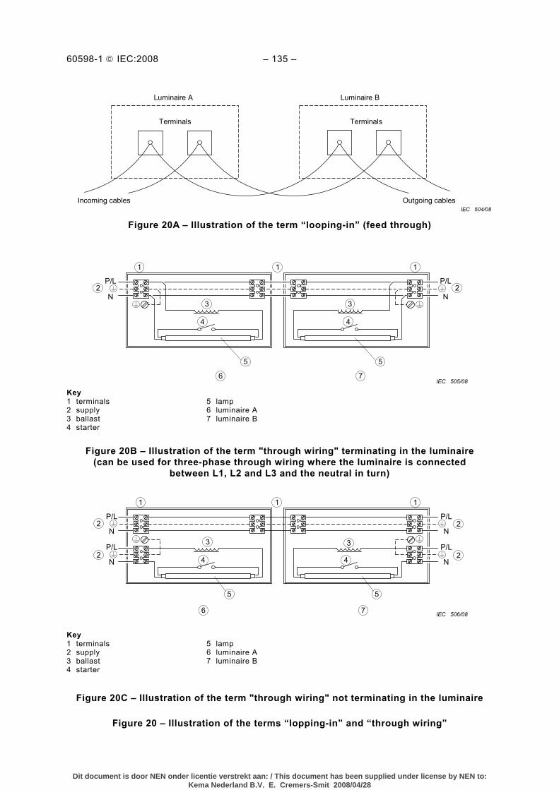
1.2.48 looping-in (feed through) system of mains supply connection to two or more luminaires where each supply conductor is taken into and out of the same terminal
NOTE A supply conductor may be cut to facilitate connections to a terminal (see Figure 20).
1.2.49 through wiring wiring which passes through the luminaire intended for interconnection of a row of luminaires
NOTE 1 Some countries do not permit joints in through wiring.
NOTE 2 The luminaire may or may not be electrically connected to the through wiring (see Figure 20).
1.2.50 starting device apparatus that, by itself or in combination with other components in the circuit, provides the appropriate electrical conditions to start a discharge type of lamp
1.2.51 starter starting device, usually for fluorescent lamps, that provides for the necessary preheating of the electrodes and in combination with the series impedance of the ballast, causes a surge in the voltage applied to the lamp
Dit document is door NEN onder licentie verstrekt aan: / This document has been supplied under license by NEN to:Kema Nederland B.V. E. Cremers-Smit 2008/04/28
1.2.52 ignitor starting device that generates voltage pulses to start a discharge lamp and that does not provide for preheating of electrodes
1.2.53 terminal block assembly of one or more terminals in or on a housing or body of insulating material to facilitate interconnection between conductors
1.2.54 rough service luminaire luminaire designed to withstand severe mechanical handling
NOTE 1 The luminaire may:
– be permanently fixed, or – be temporarily fixed on a construction or stand, or – incorporate an integral stand or handle.
NOTE 2 Such luminaires are for use where normally rough circumstances occur, or where temporary lighting is required, for example on building sites, engineering workshops and similar applications.
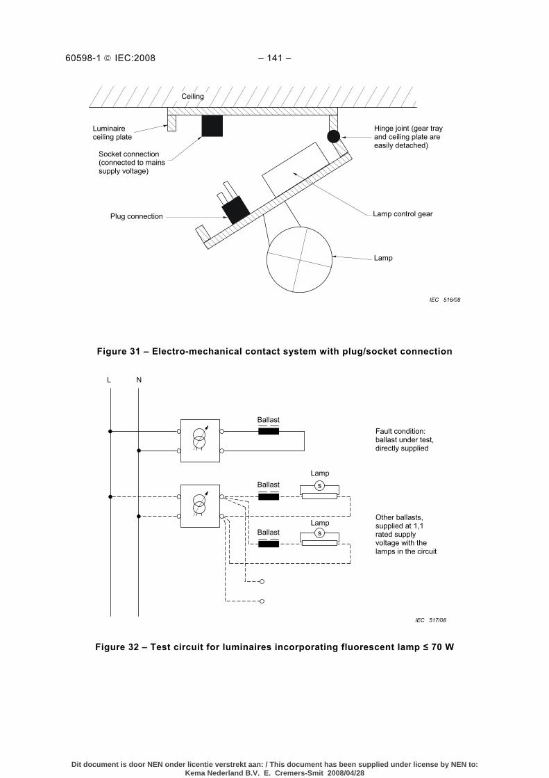
1.2.55 electro-mechanical contact system connection system within a luminaire by which the main part carrying the lampholder is electrically and mechanically connected to the base plate or suspension device
It may or may not incorporate an adjusting device.
The system may be dedicated to a specific luminaire design or may provide for connection of a variety of luminaire types.
Figure 31 describes an electro-mechanical contact system as defined in 1.2.55. As such the requirements of 4.11.6 and 7.2.1 apply.
Because, in the situation described, the base and gear tray are unique and non-interchangeable, the base plate does not require marking with the rated current of the electrical connection, as specified in 3.2.
1.2.56 extra-low voltage d.c. supplied fluorescent luminaire luminaire for operation from a battery voltage not exceeding 48 V d.c. nominal and incorporating a d.c./a.c. inverter using transistors for supplying power to one or more fluorescent lamps
NOTE 1 Extra-low voltage d.c. supplied fluorescent luminaires may generate internal voltages higher than the supply power, and thus not belong to class III. A risk of electric shock should be taken into account and guarded against with such luminaires.
NOTE 2 The value of 48 V is under consideration.
1.2.57 mounting surface part of any building, furniture or other structure which a luminaire may in any way be attached to, suspended from, stood on or placed upon in normal use and which will or is intended to support the luminaire
1.2.58 integral component component which forms a non-replaceable part of a luminaire and which cannot be tested separately from the luminaire
Dit document is door NEN onder licentie verstrekt aan: / This document has been supplied under license by NEN to:Kema Nederland B.V. E. Cremers-Smit 2008/04/28
1.2.59 self-ballasted lamps unit which cannot be dismantled without being permanently damaged, provided with a lamp cap and incorporating a light source and any additional elements necessary for starting and stable operation of the light source
NOTE 1 The light source component of a self-ballasted lamp is not replaceable.
NOTE 2 The ballast component is part of the self-ballasted lamp; it is not part of the luminaire. It is discarded at the end of the life of the unit.
NOTE 3 For test purposes, self-ballasted lamp units should be regarded as conventional lamps.
NOTE 4 For examples and further information, see IEC 60972.
1.2.60 semi-luminaire unit similar to a self-ballasted lamp but designed to utilize a replaceable light source and/or starting device
NOTE 1 The light source component and/or starting device of a semi luminaire is readily replaceable.
NOTE 2 The ballast component is not replaceable and is not disposed of each time a light source is replaced.
NOTE 3 A lampholder is required for a supply connection.
NOTE 4 For examples and further information, see IEC 60972.
1.2.61 plug-ballast/transformer ballast or transformer incorporated in an enclosure provided with an integral plug as the means of connection to the electrical supply
1.2.62 mains socket-outlet-mounted luminaire luminaire provided with an integral plug as the means of both mounting and connection to the electrical supply
1.2.63 clip-mounted luminaire integral assembly of a luminaire and resilient spring clip, securing the luminaire in position on its mounting surface by a single hand action
1.2.64 lamp connectors set of contacts specially designed to provide a means of electrical contact but not to support the lamp
1.2.65 mains socket-outlet accessory having socket-contacts designed to engage with the pins or blades of a mains plug and having terminals for the connection of cables or cords
1.2.66 rewireable luminaire luminaire so constructed that the supply cord can be replaced using general purpose tools
1.2.67 non-rewireable luminaire luminaire so constructed that the supply cord cannot be separated from the luminaire using general purpose tools without making the luminaire permanently unusable
Dit document is door NEN onder licentie verstrekt aan: / This document has been supplied under license by NEN to:Kema Nederland B.V. E. Cremers-Smit 2008/04/28
1.2.68 lamp control gear devices employed for the control of lamps, for example ballasts, transformers and step-down convertors
NOTE The definition does not include devices for the switching of lamps or the control of brightness such as dimmers and daylight sensors.
1.2.69 (Not used at present)
1.2.70 dummy lamp device incorporating a cap which is in compliance with the requirements of IEC 60061
1.2.71 self-shielded lamp tungsten halogen lamp or metal halide lamp for which the luminaire needs no protective shield for protection against UV emission or lamp shattering
1.2.72 external flexible cable or cord flexible cable or cord for external connection to the input or output circuit, fixed to or assembled with, the luminaire according to one of the following methods of attachment:
– type X attachment: method of attachment of the cable or cord such that it can be easily replaced.
NOTE 1 The flexible cable or cord may be specially prepared and only available from the manufacturer or his service agent.
NOTE 2 A specially prepared cable or cord may also include a part of the luminaire.
– type Y attachment: method of attachment of the cable or cord such that any replacement can only be made by the manufacturer, his service agent or similarly qualified person.
NOTE 3 Type Y attachment may be used either with an ordinary or a special flexible cable or cord.
– type Z attachment: method of attachment of the cable or cord such that it cannot be replaced without breaking or destroying the luminaire
1.2.73 functional earthing earthing of a point in a system or in an installation or in equipment, which is necessary for the proper function, but does not form part of the protection against electric shock
1.2.74 inter-connecting cable wiring or wiring assembly between two main parts of a luminaire as supplied by the luminaire manufacturer and which can be regarded as being part of the luminaire
NOTE A wiring assembly may contain a combination of different wiring, e.g. to feed through the supply voltage, to provide earthing, to supply starting and working voltages and wiring providing functional connection. Examples of applications are: between a luminaire and a control gear box, a mounting box or a connector fitting to a track system.
1.2.75 ferrule mechanical fixture, generally a rigid tube, used to confine the stripped end of a cable
Dit document is door NEN onder licentie verstrekt aan: / This document has been supplied under license by NEN to:Kema Nederland B.V. E. Cremers-Smit 2008/04/28
1.2.76 impulse withstand categories (former term “overvoltage categories”) numeral defining a transient overvoltage condition
NOTE 1 Impulse withstand categories I, II, III and IV are used.
NOTE 2 The following explanation is taken from IEC 60364-4-443 (withdrawn).
a) Purpose of classification of impulse withstand categories
Impulse withstand categories are to distinguish different degrees of availability of equipment with regard to required expectations on continuity of service and on an acceptable risk of failure.
By selection of impulse withstand levels of equipment insulation, coordination can be achieved in the whole installation reducing the risk of failure to an acceptable level providing a basis for overvoltage control.
A higher characteristic numeral of an impulse withstand category indicates a higher specific impulse withstand of the equipment and offers a wider choice of methods for overvoltage control.
The concept of impulse withstand categories is used for equipment energized directly from the mains.
b) Description of impulse withstand categories
Equipment of impulse withstand category I is equipment which is intended to be connected to the fixed electrical installations of buildings. Protective means are taken outside the equipment – either in the fixed installation or between the fixed installation and the equipment – to limit transient overvoltages to the specific level.
Equipment of impulse withstand category II is equipment to be connected to the fixed electrical installations of buildings.
Equipment of impulse withstand category III is equipment which is part of the fixed electrical installations and other equipment where a higher degree of availability is expected.
Equipment of impulse withstand category IV is for use at or in the proximity of the origin of the electrical installations of buildings upstream of the main distribution board.
1.2.77 circuits and circuit characteristics 1.2.77.1 primary circuit circuit which is directly connected to the a.c. mains supply
It includes, for example, the means for connection to the a.c. mains supply, the primary windings of transformers, motors and other loading devices
[IEC 60950-1, Definition 1.2.8.4]
1.2.77.2 secondary circuit circuit which has no direct connection to a primary circuit and derives its power from a transformer, converter or equivalent device, or from a battery
[IEC 60950-1, Definition 1.2.8.5]
Exception: In autotransformers, although having direct connection to a primary circuit, the tapped part of the transformer is also deemed to be a secondary circuit in the above sense.
NOTE Mains transients in such a circuit are attenuated by the corresponding primary windings. Inductive ballasts also reduce the mains transient voltage height. Therefore, components located after a primary circuit or after an inductive ballast can be suited for an impulse withstand category of one step lower, see Annex U.
Dit document is door NEN onder licentie verstrekt aan: / This document has been supplied under license by NEN to:Kema Nederland B.V. E. Cremers-Smit 2008/04/28
1.2.78 touch current electric current passing through a human body or through an animal body when it touches one or more accessible parts of an installation or of equipment
[IEV 195-05-21]
NOTE In this standard, the human body is represented by the networks in Figures G.2 or G.3.
1.2.79 protective conductor current current which flows in a protective conductor
NOTE This current may have an influence on the operation of RCD’s (residual current protection devices) connected in the same circuit.
1.2.80 electric burn burning of the skin or of an organ, caused by passing an electric current across or through the surface
[IEV 604-04-18]
1.2.81 means of adjustment part of a luminaire, which may be the lamp compartment, obviously intended to be manipulated by the user during use of the luminaire, e.g. to redirect the light beam
1.2.82 arms reach zone of accessibility to touch extending from any point on a surface where persons usually stand or move about to the limits which a person can reach with the hand, in any direction, without assistance
[IEV 195-06-12]
NOTE IEC 60364-4-41 incorporates a drawing representing the zone of accessibility. In general terms, the height being 2,5 m from the floor, and the width being 1,25 m in all horizontal directions from the locations a person may be.
1.2.83 terminal block with integrated screwless earthing contact terminal with earthing connection performed by means of an integrated contact or by means of an auxiliary contact without additional assembly actions (e.g. screwing) when fitted
12.84 detachable cord flexible cable or cord, for supply or interconnection, intended to be connected to the luminaire by means of a suitable appliance connector
NOTE A detachable cord is considered to be easily replacable.
1.2.85 tool screwdriver, coin or other object that may be used to operate a screw or similar fixing means
1.2.86 specially prepared cord a flexible cable or cord the replacement of which with another non-special cable or cord would create a hazard or diminish safety
Dit document is door NEN onder licentie verstrekt aan: / This document has been supplied under license by NEN to:Kema Nederland B.V. E. Cremers-Smit 2008/04/28
This section describes the classification of luminaires.
Luminaires are classified according to the type of protection against electric shock, the degree of protection against ingress of dust, solid objects and moisture, and the material of the supporting surface.
2.2 Classification according to type of protection against electric shock
Luminaires shall be classified according to the type of protection against electric shock provided, as class I, class II or class III (see definitions in Section 1).
Luminaires shall have only a single classification. For example, for a luminaire with a built-in extra-low voltage transformer with provision for earthing, the luminaire shall be classified as class I and part of the luminaire shall not be classified as class III even though the lamp compartment is separated by a barrier from the transformer compartment.
Semi-luminaires shall comply with all relevant requirements for class II luminaires without being provided with the class II symbol.
Unless a luminaire has been specifically designed for use with semi-luminaires, the luminaire manufacturer is not responsible for continued IEC 60598 conformity in the situation where the user has replaced specified lamp types with semi-luminaires. The semi-luminaire manufacturer has a responsibility to provide information with respect to limitations of use.
NOTE The class II symbol is omitted in order to avoid the symbol being applied to the complete luminaire in which the semi-luminaire is used.
2.3 Classification according to degree of protection against ingress of dust, solid objects and moisture
Luminaires shall be classified in accordance with the "IP number" system of classification described in IEC 60529.
Symbols for the degrees of protection are given in Section 3.
Tests for the degrees of protection are given in Section 9.
NOTE 1 Luminaires classified as watertight are not necessarily suitable for operation under water. Pressure watertight luminaires should be used for such applications.
NOTE 2 The IP numbers are the principal marking on luminaires, but symbols may be used in addition to IP numbers, if desired.
Dit document is door NEN onder licentie verstrekt aan: / This document has been supplied under license by NEN to:Kema Nederland B.V. E. Cremers-Smit 2008/04/28
2.4 Classification according to material of supporting surface for which the luminaire is designed
Luminaires shall be classified according to whether they are suitable for direct mounting on normally flammable surfaces or are only suitable for mounting on non-combustible surfaces as follows:
Classification
– Luminaires suitable for direct mounting on normally flammable surfaces
Symbol No symbol required
– Luminaires not suitable for direct mounting on normally flammable surfaces
The relevant symbol – see Figure 1
NOTE Readily flammable surfaces are not suitable for the direct mounting of luminaires. Requirements for luminaires classified as primarily intended for direct mounting on normally flammable surfaces are given in Section 4 and related tests in Section 12.
2.5 Classification according to the circumstances of use
Luminaires shall be classified according to whether they are intended for normal use or for rough service.
Classification Symbol
– Luminaires for normal use No symbol – Luminaires for rough service Symbol – see Figure 1
3 SECTION 3: MARKING
3.1 General
This section specifies the information to be marked on luminaires.
3.2 Marking on luminaires
The following information shall be distinctly and durably marked on the luminaire (see Table 3.1).
a) Marking to be observed when replacing lamps or other replaceable components, shall be visible on the outside of the luminaire (except the mounting side) or behind a cover which is removed during lamp or other component replacement and with the lamp removed.
b) Marking to be observed during installation shall be visible during installation on the outside of the luminaire or behind a cover or part which is removed during installation.
c) Marking to be observed after installation shall be visible with the luminaire assembled and installed as for normal use and with the lamp in place.
Marking may be on ballasts provided the conditions under a) or b) above, as appropriate, are fulfilled. See Table 3.1 for details.
Dit document is door NEN onder licentie verstrekt aan: / This document has been supplied under license by NEN to:Kema Nederland B.V. E. Cremers-Smit 2008/04/28
The relevant symbol for luminaires not suitable for direct mounting on normally flammable surfaces
3.2.12 Termination
3.2.17 c Interconnected luminaires
3.2.21 The relevant symbol for not suitable for covering with thermally insulating material
3.2.13 Lighted objects d
3.2.14 Rough service
3.2.20 Means of adjustment
a 3.2.8 Rated wattage. For luminaires for discharge lamps with remote control gear, the marking may be replaced by the instruction: “For lamp designation, see control gear’’.
b 3.2.2 Rated voltage. For luminaires for discharge lamps, if the ballast is not built into the luminaire, the luminaire shall be marked with the working voltage instead of the mains voltage. For luminaires with built-in transformers for filament lamps, see IEC 60598-2-6.
c 3.2.17 Interconnected luminaires. For fixed luminaires, this information may alternatively be provided within the installation instructions.
d 3.2.13 Lighted objects. Only the symbol shall be provided on the luminaire. The explanation of the symbol shall be provided in the instruction accompanying the luminaire, where not already provided on the luminaire.
The earthing symbol referred to in 3.2.12 may be marked on the ballast, instead of the luminaire, if the ballast is of a non-replaceable type. The height of graphical symbols shall not be less than 5 mm, except for symbols for class II and class III luminaires, and may be reduced to a minimum of 3 mm where the space available for marking is restricted. The height of letters and numerals either shown separately or with or as part of symbols shall not be less than 2 mm.
For combination luminaires where the type references or the rated inputs are different for different combinations, the main part and the alternative parts may be marked with a type reference or a rated input, as appropriate, provided that the type can be identified and the rated input of the complete unit may be established from a catalogue or a similar document.
For luminaires with electro-mechanical contact systems, the base plate shall be marked with the rated current of the electrical connection if the system can be used with a variety of different luminaire types.
3.2.1 Mark of origin (this may take the form of a trade mark, the manufacturer's identification mark or the name of the responsible vendor).
3.2.2 Rated voltage(s) in volts. Luminaires for tungsten filament lamps shall be marked only if the rated voltage is different from 250 V.
Portable class III luminaires shall be marked with the rated voltage on the outside of the luminaire.
Dit document is door NEN onder licentie verstrekt aan: / This document has been supplied under license by NEN to:Kema Nederland B.V. E. Cremers-Smit 2008/04/28
3.2.3 The rated maximum ambient temperature ta, if other than 25 °C (see Figure 1).
NOTE Exceptions to this general requirement may be specified in particular parts of IEC 60598-2.
3.2.4 Symbol for class II luminaires where applicable (see Figure 1).
For portable luminaires provided with a supply cord, the symbol for class II construction, if applicable, shall be on the outside of the luminaire.
The class II symbol shall not be applied to semi-luminaires.
3.2.5 Symbol for class III luminaires where applicable (see Figure 1).
3.2.6 Marking (if applicable) with IP numbers for degree of protection against ingress of dust, solid objects and moisture (see Figure 1 and Annex J). Where X is used in an IP number in Figure 1, it indicates a missing numeral in the example, but both of the appropriate numerals shall be marked on the luminaire.
In cases where different IP numbers apply to distinct parts of the luminaire, the lower number shall be marked on the type label on the luminaire, even if IP20, whereas the higher number shall be marked separately on the part concerned. In cases where shades or similar devices upgrading e.g. an IP20 luminaire to a higher IP rating when mounted, the IP20 marking shall be made invisible by the device in question without destroying the marking and the device shall visibly be provided with a new IP rating. The instruction sheet supplied with the luminaire shall include details of the IP numbers applying to the various parts of the luminaire. The use of different IP numbers on different parts of a luminaire or devices to upgrade the IP rating e.g. to a higher IP rating is only applicable to fixed luminaires.
For recessed luminaires with two IP ratings, both ratings shall be visible during installation and it shall be obvious to which parts of the luminaire the ratings refer. The relevant information shall be provided even if the rating is IP20 or the lower rating is specified as ordinary
Marking of IP20 on ordinary luminaires is not required.
3.2.7 Maker's model number or type reference.
3.2.8 Rated wattage or the designation as indicated on the lamp data sheet of the type or types of lamp for which the luminaire is designed. Where the lamp wattage alone is insufficient, the number of lamps and the type shall also be given.
Luminaires for tungsten filament lamps shall be marked with the maximum rated wattage and number of lamps.
Marking of maximum rated wattage for luminaires for tungsten filament lamps with more than one lampholder may be in the form:
"n × MAX... W", n being the number of lampholders.
3.2.9 Where applicable, the relevant symbol (see Figure 1) for luminaires not suitable for direct mounting on normally flammable surfaces. The symbol shall be explained on the luminaire or in the manufacturer’s instructions provided with the luminaire. See Table N.1. The minimum size of the symbol shall be 25 mm for each side.
Dit document is door NEN onder licentie verstrekt aan: / This document has been supplied under license by NEN to:Kema Nederland B.V. E. Cremers-Smit 2008/04/28
3.2.10 Information concerning special lamps, if applicable.
In particular, this applies to the symbols (see Figure 1) for luminaires for use with high-pressure sodium lamps having either an internal starting device or requiring an external ignitor where the lamp is required to be marked with the same symbol according to IEC 60662.
3.2.11 Symbol (see Figure 1), if applicable, for luminaires for lamps of similar shape to "cool beam" lamps but where the use of a dichroic reflectorized "cool beam" lamp might impair safety.
3.2.12 Except for type Z attachments, terminations shall be marked to identify live, neutral and earth in case of connection of the luminaire to the supply mains to ensure safe and satisfactory operation.
Symbols, when applied, indicating mains supply terminations shall be according to IEC 60417.
The earthing termination shall be marked by the relevant symbol of IEC 60417 only.
Leads (tails) used for the connection to extra low voltage d.c. supply, shall be colour coded red to indicate its intended connection to the positive termination, and shall be colour coded black to indicate its intended connection to the negative termination. Fixed terminations, when applied, shall be marked with the "+" sign to indicate the positive connection, and shall be marked with the "–" sign to indicate the negative connection.
NOTE 2 Terminations can be found at leads (tails), connection or terminal blocks and terminals of another construction.
Luminaires with supply cords which are not fitted with a plug shall include with the manufacturers instructions any information necessary to ensure safe connection, e.g. deviations from the national standardised colour coding of the cores where this does not create the possibility of an unsafe situation during installation, use or maintenance.
NOTE 3 In some countries, luminaires with supply cords which are intended to be connected to the supply via a socket-outlet and which are not fitted with a plug are not permitted.
3.2.13 Symbol (see Figure 1) for minimum distance from lighted objects, if applicable, for luminaires which might otherwise overheat the lighted objects due to, for example, the applied lamp type, the shape of the reflector, the adjustability of the mounting means or the location of mounting as indicated in the installations instructions.
The minimum distance marked shall be determined by the temperature test described in item j) of 12.4.1.
The distance is measured on the optical axis of the luminaire from that part of the luminaire or lamp which is nearest to the lighted object.
The symbol for minimum distance and explanation of its meaning shall also be given either on the luminaire or in the instructions with the luminaire.
3.2.14 Symbol (see Figure 1), if applicable, for rough service luminaires.
Dit document is door NEN onder licentie verstrekt aan: / This document has been supplied under license by NEN to:Kema Nederland B.V. E. Cremers-Smit 2008/04/28
3.2.15 Symbol (see Figure 1), if applicable, for luminaires which are designed for use with bowl mirror lamps.
NOTE Separate bowls for attachment to GLS lamps without reference to luminaire testing are not within the scope of this standard.
3.2.16 Luminaires incorporating a protective shield shall be marked as follows:
"Replace any cracked protective shield" or with the symbol (see Figure 1).
3.2.17 The maximum number of luminaires that may be interconnected or the maximum total current that may be drawn by means of couplers provided for looping-in connection to the mains supply. For fixed luminaires, this information may alternatively be provided within the installation instructions.
3.2.18 A warning symbol or notice for luminaires with ignitors intended for use with double-ended high pressure discharge lamps and luminaires with double-capped Fa8 tubular lamps if the voltage measured according to Figure 26 exceeds 34 V peak.
a) Warning symbol in accordance with IEC 60417-5036 (2002-10) visible during replacement of the lamp. The symbol shall be explained on the luminaire or in the manufacturer's instructions provided with the luminaire, or
b) A warning notice near to the holder of a replaceable ignitor or replaceable switching element, if any: "Attention, remove replaceable device before replacement of lamp. After lamp-replacement reinsert replaceable device".
3.2.19 Symbol (see Figure 1) for luminaires which are designed to be used only with self-shielded tungsten halogen lamps or self-shielded metal halide lamps.
3.2.20 Where necessary, the means of adjustment where not obvious, needs to be identified.
NOTE Appropriate marking includes symbols (e.g. arrows) to indicate direction of movement, descriptive text or colours.
3.2.21 The relevant symbol (see Figure 1) for luminaires not suitable for covering with thermally insulated material. The symbol shall be explained on the luminaire or in the manufacturer’s instructions provided with the luminaire. See Table N.1. The minimum size of the symbol shall be 25 mm for each side.
NOTE A warning notice and symbol is required when a luminaire is not suitable for covering with thermally insulated material.
3.2.22 Symbol (see Figure 1 from IEC 61558-1), if applicable, for luminaires with internal replaceable fuses. Such a luminaire shall, in addition, be provided with information regarding the rated current (in A or mA) of the fuse. Where the time/current characteristic of the fuse is important for safety, the rating and type of any fuse shall be marked on the holder or in the proximity of the fuse in accordance with what is stated in the relevant fuse standard.
3.3 Additional information
In addition to the above marking, all details which are necessary to ensure proper installation, use and maintenance shall be given either on the luminaire, semi-luminaire or on built-in ballasts or in the manufacturer's instructions provided with the luminaire, for instance:
Written instructions related to safety shall be in a language which is acceptable in the country in which the equipment is to be installed.
Dit document is door NEN onder licentie verstrekt aan: / This document has been supplied under license by NEN to:Kema Nederland B.V. E. Cremers-Smit 2008/04/28
3.3.1 For combination luminaires, the permissible ambient temperature, the class of protection or the protection against ingress of dust, solid objects and moisture of an alternative part if not at least equal to that of the basic luminaire.
3.3.2 Nominal frequency in hertz.
3.3.3 Operating temperatures:
a) The rated maximum operating temperature (of a winding) tw in degrees Celsius. b) The rated maximum operating temperature (of a capacitor) tc in degrees Celsius. c) The maximum temperature to which the insulation of supply cables and interconnecting
cables will be subjected within the luminaire under the most unfavourable conditions of normal operation, if in excess of 90 °C (see note c to Table 12.2 relating to unsleeved fixed wiring). The symbol to indicate this requirement is given in Figure 1.
d) Spacing requirements to be observed during installation.
3.3.4 In case a luminaire is only suitable for direct mounting on non-combustible surfaces and the relevant symbol (see Figure 1) is not applied, a warning notice shall be attached to the luminaire or given in the manufacturer’s instructions explaining that the luminaire can under no circumstances be mounted on normally flammable surfaces.
Because of their application, luminaires which are provided with an adaptor for mounting on a track shall meet the requirements for direct mounting on normally flammable surfaces.
3.3.5 A wiring diagram, except where the luminaire is suitable for direct connection to the mains supply.
3.3.6 Special conditions for which the luminaire, including the ballast, is suitable, for instance, whether or not the luminaire is intended for looping-in.
3.3.7 Luminaires provided with metal halide lamps shall, if applicable, be provided with the following warning notice:
“The luminaire shall only be used complete with its protective shield”.
3.3.8 The manufacturer of semi-luminaires shall supply information on limitations of use of such devices, particularly where overheating may be caused by the position or thermal distribution of the replaceable light source being different from the light sources they will replace.
3.3.9 In addition, the manufacturer shall be prepared to supply information on the power factor and the supply current.
For connections suitable for both resistive and inductive loads, the rated current for the inductive load shall be indicated between brackets and shall immediately follow the rated current for the resistive load. The marking may accordingly be as follows:
3(1)A 250 V or 3(1)/250 or 250)1(3
NOTE 1 This marking is in accordance with IEC 61058-1.
NOTE 2 The rated current values do not apply to circuits in general but only to the rating of the luminaire as a whole.
3.3.10 Suitability for use "indoors" including the related ambient temperature.
Dit document is door NEN onder licentie verstrekt aan: / This document has been supplied under license by NEN to:Kema Nederland B.V. E. Cremers-Smit 2008/04/28
3.3.11 For luminaires using remote control gear, the range of lamps for which the luminaire is designed.
3.3.12 For clip-mounted luminaires, a warning when the luminaire is not suitable for mounting on tubular material.
3.3.13 The manufacturer shall provide the specifications of all protective shields.
3.3.14 Where necessary for correct operation, the luminaire shall be marked with the symbol for nature of supply (see Figure 1).
3.3.15 The rated current at rated voltage shall be declared by the manufacturer for any socket outlet incorporated in the luminaire, if less than the rated value.
3.3.16 The information about rough service luminaires concerning:
– the connection to IPX4 rated socket outlets; – the correct mounting taking into account the temporary installation; – the correct fixing to a stand, and also where the stand is not supplied with the luminaire, the
maximum height of a possible stand, and its required stability by the indication of the number and minimum length of the legs.
3.3.17 For luminaires with type X, Y or Z attachments, the mounting instructions shall contain the substance of the following information:
– for type X attachments having a specially prepared cord If the external flexible cable or cord of this luminaire is damaged, it shall be replaced by a
special cord or cord exclusively available from the manufacturer or his service agent. – for type Y attachments If the external flexible cable or cord of this luminaire is damaged, it shall be exclusively
replaced by the manufacturer or his service agent or a similar qualified person in order to avoid a hazard.
– for type Z attachments The external flexible cable or cord of this luminaire cannot be replaced; if the cord is
damaged, the luminaire shall be destroyed.
3.3.18 Luminaires which are other than ordinary, provided with a PVC supply cord, shall be provided with information about the intended use, i.e. “For indoor use only”.
3.3.19 For luminaires which generate a protective conductor current greater than 10 mA and intended for permanent connection, the protective conductor current shall be clearly stated in the manufacturers’ instructions.
3.3.20 Wall mounted and adjustable luminaires not intended to be mounted within arms reach shall be provided with information to advise their correct installation, i.e. “Only to be installed outside arms reach”.
3.4 Test of marking
Compliance with the requirements of 3.2 and 3.3 is checked by inspection and by the following test:
The durability of the marking is checked by trying to remove it by rubbing lightly for 15 s with a piece of cloth soaked with water and, after drying, for a further 15 s with a piece of cloth soaked with petroleum spirit and by inspection after the tests detailed in Section 12 have been completed.
Dit document is door NEN onder licentie verstrekt aan: / This document has been supplied under license by NEN to:Kema Nederland B.V. E. Cremers-Smit 2008/04/28
After the test, the marking shall be legible, marking labels shall not be easily removable and they shall show no curling.
NOTE The petroleum spirit used should consist of a solvent hexane with a content of aromatics of maximum 0,1 % by volume, a value of 29 % for kauri-butanol, an initial boiling-point of approximately 65 °C, a dry-point of approximately 69 °C and a density of approximately 0,68 g/cm3.
4 SECTION 4: CONSTRUCTION
4.1 General
This section specifies general constructional requirements for luminaires. See also Annex L.
4.2 Replaceable components
Luminaires incorporating components or parts intended to be replaceable shall be so designed that there is sufficient space to permit replacement of such components or parts without difficulty and without impairing safety.
NOTE Sealed-in components and riveted parts are not replaceable components.
4.3 Wireways
Wireways shall be smooth and free from sharp edges, burrs, flashes and the like, which might cause abrasion of the insulation of the wiring. Parts such as metal set screws shall not protrude into wireways.
Compliance is checked by inspection and, if necessary, by dismantling and reassembling the luminaire.
4.4 Lampholders
4.4.1 The requirements for electrical safety of integral lampholders shall be those applicable to the luminaire as a whole with the lampholder and lamp in fully assembled position, as for normal use.
In addition, integral lampholders shall, when mounted in the luminaire, comply with the requirements concerning safety during insertion of the lamp as specified in the appropriate lampholder standard.
4.4.2 Connection of wiring to integral lampholder contacts may be made by any method giving reliable electrical contact over the service life of the lampholder.
4.4.3 Luminaires for tubular fluorescent lamps designed for end-to-end mounting shall be so designed that the lamp may be changed in the middle luminaire of a row without adjusting any other luminaire. In multi-lamp luminaires for tubular fluorescent lamps, the changing of any one lamp shall not impair the security of the other lamps.
Compliance with the requirements of 4.4.1 to 4.4.3 is checked by inspection.
4.4.4 Lampholders which are put into position by the user shall be capable of easy and correct positioning.
The distance between the pair of fixed lampholders for a fluorescent lamp intended to be set in a fixed position shall comply with the relevant standard sheet of IEC 60061-2 or (if IEC 60061-2 does not apply) the lampholder manufacturer's mounting instructions. Lampholders for tungsten filament lamps and lampholders for single-capped fluorescent lamps shall be adequately fixed to the body of the luminaire. The fixing device of lampholders shall
Dit document is door NEN onder licentie verstrekt aan: / This document has been supplied under license by NEN to:Kema Nederland B.V. E. Cremers-Smit 2008/04/28
have adequate mechanical strength so as to withstand such rough handling as may be expected in normal use. These requirements apply both to lampholders put in position by the user and to lampholders put in position by the luminaire manufacturer.
Compliance is checked by inspection, measuring and, if applicable, by the following mechanical tests:
i) Lampholders for a fluorescent lamp, with a test-cap in position, are subjected, for 1 min, to a pressure applied to the centre of the cap in the direction of its axis of: – 15 N for G5 lampholders;
– 30 N for G13 lampholders;
– 30 N for lampholders for single-capped fluorescent lamps (G23, G10q, GR8 etc.). Values for other lampholders are under consideration.
After the test, the distance between the holders shall comply with the relevant standard sheet of IEC 60061-2 and the lampholder shall show no damage. The test-cap for this test shall comply with the following standard sheets in IEC 60061-3:
7006-47C for G5 lampholders,
7006-60C for G13 lampholders,
test-caps for other lampholders are under consideration.
After the test on lampholders for single-capped fluorescent lamps, the lampholder shall not have moved from its position and the fixing device shall show no permanent deformation, so that the lamp, when reinserted, will come in its intended position.
ii) Mounting brackets for Edison screw or bayonet-capped lampholders are subjected to testing for 1 min, to the following bending moments:
for E14 and B15 lampholders 1,2 Nm;
for E26, E27 and B22 lampholders 2,0 Nm;
for E39 and E40 lampholders 4,0 Nm
After the test, the lampholder shall not have moved from its position and the fixing device shall show no permanent deformation, so that the lamp, when reinserted, shall be in its intended position.
4.4.5 For luminaires with ignitors, the peak pulse voltage occurring across contacts in lampholders which are part of the pulse voltage circuit shall not be greater than the pulse voltage marked on the lampholder or, in the absence of such marking, shall not be greater than:
– for 250 V rated lampholders 2,5 kV – for 500 V rated ES lampholders 4 kV – for 750 V rated ES lampholders 5 kV
Compliance is checked by measurement of the voltage occurring across the lampholder contacts during the pulse test of 10.2.2 for luminaires with ignitors.
4.4.6 For luminaires with ignitors incorporating Edison screw lampholders, the centre contact of the lampholder shall be connected to the lead which supplies the pulse voltage.
Compliance is checked by inspection.
4.4.7 The insulating parts of lampholders and plugs incorporated in rough service luminaires shall be of a material resistant to tracking.
Compliance is checked by the test of 13.4.
Dit document is door NEN onder licentie verstrekt aan: / This document has been supplied under license by NEN to:Kema Nederland B.V. E. Cremers-Smit 2008/04/28
4.4.8 Lamp connectors shall comply with all the requirements for lamp holders other than those related to retaining the lamp in position. Means for retaining the lamp shall be provided by other parts of the luminaire.
Compliance is checked by inspection and test as required by 4.4.1 to 4.4.7.
NOTE The difference between lamp connectors and lampholders is clearly identified on the relevant data sheets of IEC 60061.
4.4.9 Caps or bases originally developed for single-capped ELV lamps shall not be used in luminaires intended for use with general purpose tungsten halogen lamps with rated voltages higher than 50 V.
NOTE Examples of such ELV fits are: G4, GU4, GY4, GX5.3, GU5.3, G6.35, GY6.35, GU7 and G53.
Luminaires intended for use with GU10 lamps only (with aluminised reflector) shall be provided with GU10 lamp holders only.
Compliance is checked by inspection.
4.5 Starter holders
Starter holders in luminaires other than class II shall accept starters which comply with IEC 60155.
Class II luminaires may require starters of class II construction.
For class II luminaires where the starter can be touched with the standard test finger when the luminaire is fully assembled for use or open for the replacement of lamps or starters, the starter holder shall be one accepting only starters complying with the requirements for starters for class II luminaires given in IEC 60155.
Compliance is checked by inspection.
4.6 Terminal blocks
If luminaires are provided with connecting leads (tails) requiring a separate terminal block for the connection to the fixed wiring, adequate space for this terminal block shall be provided within the luminaire, or within a box delivered with the luminaire, or specified by the manufacturer.
This requirement applies to terminal blocks for connecting leads (tails) with conductor nominal cross-sectional areas not exceeding 2,5 mm2.
Compliance is checked by measurement and by an installation test, using one terminal block for each two conductors to be connected together, as shown in Figure 2, and fixed wiring having a length of approximately 80 mm. The dimensions of the terminal blocks are those specified by the manufacturer or, in the absence of such a specification, 10 mm × 20 mm × 25 mm.
NOTE 1 Unsecured terminal blocks are permitted when they are so designed and insulated that creepage distances and clearances in accordance with Section 11 are always maintained for any position of the terminal block, and that damage to internal wiring is prevented.
NOTE 2 A Class II luminaire connected to the supply by means of connecting leads (tails) can be accepted provided that all relevant requirements are complied with.
4.7 Terminals and supply connections
4.7.1 In portable luminaires of class I and II and in fixed luminaires of class I and II that are frequently adjusted, adequate precautions shall be taken to prevent metal parts from becoming
Dit document is door NEN onder licentie verstrekt aan: / This document has been supplied under license by NEN to:Kema Nederland B.V. E. Cremers-Smit 2008/04/28
live due to a detached wire or screw. This requirement applies to all terminals (including supply terminals).
NOTE The requirement may be met by securing the wires adjacent to their entry to the terminals, by suitable dimensioning of the enclosure for the terminals, by the use of an enclosure of insulating material or by the provision of an insulating lining in the enclosure.
Examples of methods deemed efficient to prevent a wire from becoming detached are:
a) wires are retained by a cord anchorage adjacent to the terminals;
b) conductor is clamped by a spring type screwless terminal;
c) the wire conductor is anchored to the tag before soldering, unless breakage close to the soldering place is likely to occur as a result of vibration;
d) wires are twisted together in a reliable manner;
e) wires are fastened together by insulation tape, sleeves, or the like;
f) the wire conductor is inserted into a hole in a printed board, bent and soldered, the hole having a diameter slightly greater than the conductor;
g) the wire conductor is securely wrapped around the terminal by means of a special tool (see Figure 19);
h) the wire conductor is crimped to the terminal by means of a special tool (see Figure 19).
The methods under a) to h) apply to internal wiring and the methods under a) and b) to rewireable external flexible cords.
Compliance is checked by inspection and based upon the assumption that only one conductor can become detached at the same time.
4.7.2 Supply terminals shall be located or shielded in such a way that, if a wire of a stranded conductor escapes from a terminal when the conductors are fitted, there is no risk of contact between live parts and metal parts which can be touched with the standard test finger when the luminaire is fully assembled for use or open for the replacement of lamps or starters.
Compliance is checked by inspection and by the following test:
An 8 mm length of insulation is removed from the end of a flexible conductor having the largest cross-sectional area specified in Section 5. One wire of the stranded conductor is left free and the remainder are fully inserted and clamped in the terminal. The free wire is bent, without tearing the insulation back, in every possible direction, but without making sharp bends around barriers.
The free wire of a conductor connected to a live terminal shall not touch any metal part which is accessible or connected to an accessible metal part, and the free wire of a conductor connected to an earthing terminal shall not touch any live part.
This test does not apply to lampholders which have been separately approved to an appropriate IEC standard and to terminals of components where the construction method justifies a shorter length of free wire.
4.7.3 Terminals for supply cords, shall be suitable for connection to be made by means of screws, nuts or equally effective devices.
Connecting leads (tails) shall comply with the requirements of Section 5.
NOTE 1 For luminaires designed to be connected by means of rigid (solid or stranded) conductors, screwless terminals of the spring type are effective devices, including the earth connection. No requirements are specified at present for using such terminals for the connection of supply cords.
Dit document is door NEN onder licentie verstrekt aan: / This document has been supplied under license by NEN to:Kema Nederland B.V. E. Cremers-Smit 2008/04/28
NOTE 2 For luminaires designed to be connected by means of a supply cord and having a rated current not exceeding 3 A, soldered, welded, crimped and similar connections, including snap-on connectors, are effective devices, including an earth connection. Other similar connections include screwless terminals, insulation piercing or insulation displacement clamping terminals.
NOTE 3 For luminaires having a rated current exceeding 3 A, snap-on connectors are suitable if the connection can also be made without making use of the receptacle, for example, by means of a screwed connection for which a threaded hole is provided in the tab.
4.7.3.1 Welding method and material
The conductor shall be stranded or solid wire of copper materials. For thin wires, a ferrule may be used.
The welding method shall be spot welding only.
NOTE Other methods of welding are under consideration.
Welding of wire and plate is allowed, but welding of wires together is not allowed.
Welded connections are used in Type Z attachments only.
Welded connections shall withstand the mechanical, electrical and heat test in normal use.
Compliance is checked by inspection and by the following tests.
a) Mechanical test
Apply the test of 15.8.2.
If the wire is fixed by a cord anchorage, the mechanical test is not applicable.
b) Electrical test
Apply the tests of 15.9.
c) Heat test
Apply the tests of 15.9.2.3 and 15.9.2.4.
4.7.4 Terminals, other than those for supply connection, which are not covered by separate standards for components, shall comply with the requirements of Sections 14 and 15.
Terminals of lampholders, switches and similar parts used for multiple connection of internal wiring shall have dimensions adequate for the purpose and shall not be used for the connection of external wiring.
Compliance is checked by inspection and by the tests of Sections 14 and 15.
4.7.5 If the external wiring or supply cord is unsuitable for the temperatures reached inside the luminaire, either a connection shall be provided at the point of entry of the external wiring into the luminaire for the use of heat-resistant wiring after this point, or heat-resisting parts shall be supplied with the luminaire to cover the part of the wiring placed inside it, which exceeds the wiring temperature limit.
Compliance is checked by inspection.
4.7.6 If during the installation or maintenance of a luminaire, electrical connections are made by a multi-pole plug and socket, unsafe connections shall be prevented.
Compliance is checked by inspection and by trying to make unsafe connections, e.g. by shifting the plug positions. The force applied to the plug during compliance checks shall take into account forces up to 30 N in any direction.
Dit document is door NEN onder licentie verstrekt aan: / This document has been supplied under license by NEN to:Kema Nederland B.V. E. Cremers-Smit 2008/04/28
Switches shall be adequately rated and so fixed that they are secured against rotation and cannot be removed by hand.
Switches in flexible cables or cords and switched lampholders shall not be used in luminaires which are other than ordinary, unless the degree of protection against dust, solid objects or moisture of the switch is in accordance with the classification of the luminaire.
For luminaires intended for use on a polarized supply and where the luminaire has a single-pole on/off switch, the switch shall be wired into the live side of the supply or the side other than that identified as the neutral side.
Electronic switches, when incorporated in or supplied with the luminaire, shall comply with the requirements of IEC 61058-1.
Compliance is checked by inspection.
4.9 Insulating linings and sleeves
4.9.1 Insulating linings and sleeves shall be so designed that they are reliably retained in position when switches, lampholders, terminals, wires or similar parts have been mounted.
NOTE Self-hardening resins, such as epoxy resins, may be used to fix linings.
Compliance is checked by inspection and by manual test.
4.9.2 Insulated linings, sleeves and similar parts shall have adequate mechanical, electrical and thermal strength.
Compliance is checked by inspection, by manual test and by the electric strength test in accordance with Section 10. The thermal properties of wire and sleeve are checked in accordance with Section 12. Heat resistant sleeves used as covering for wires attaining a temperature exceeding the values given in Table 12.2 of Section 12 shall comply with the requirements of IEC 60684, taking into account the temperature measured on the wire in question. The sleeve shall be resistant to a temperature exceeding the temperature measured on the wire by 20 °C or withstand the following test:
a) Three test specimens of the sleeve, about 15 cm in length, are subjected to the humidity test of 9.3 and subsequently to the insulation resistance and electric strength tests according to Section 10. A suitable uninsulated copper conductor or metal rod is passed through the specimens, and the outside is covered by a metal foil in such a way that no flashover at the ends of the samples can occur. The measurement of the insulation resistance and the electric strength test is then made between the copper conductor/metal rod and the metal foil.
b) After the copper conductors/metal rods and metal foils have been removed, the specimens are placed in a heating cabinet for 240 h at a temperature of T + 20 °C, T being the measured temperature of the wire.
c) The specimens are allowed to cool to room temperature and are then prepared as indicated under item a) above.
Measurement of the insulation resistance and electric strength is then made between the copper conductor/metal rod and the metal foil.
Compliance is checked by the insulation resistance values and test voltages specified in Tables 10.1 and 10.2 in Section 10.
Dit document is door NEN onder licentie verstrekt aan: / This document has been supplied under license by NEN to:Kema Nederland B.V. E. Cremers-Smit 2008/04/28
4.10.1 For metal encased class II luminaires, contact between:
– mounting surfaces and parts with basic insulation only, – accessible metal parts and basic insulation,
shall be effectively prevented.
NOTE 1 This requirement does not exclude the use of bare conductors if adequate protection is provided.
This wiring includes internal and external wiring of the luminaire, and fixed wiring of the installation.
Class II fixed luminaires shall be so designed that the required degree of protection against electric shock is not impaired as a result of the installation of the luminaire, for example by contact with metal conduits or metal sheaths of cables.
Capacitors shall not be connected between live parts and the body of metal encased class II luminaires, with the exception of interference suppression capacitors and switches meeting the requirements of 4.8.
The interference suppression capacitors shall comply with the requirements of IEC 60384-14 and the method of their connection shall be in accordance with 8.6 of IEC 60065.
NOTE 2 Contact between accessible metal parts and the basic insulation of internal wiring may be prevented by sleeves or similar parts which comply with the requirements for supplementary insulation.
Compliance is checked by inspection.
4.10.2 Any assembly gap with a width greater than 0,3 mm in supplementary insulation shall not be coincidental with any such gap in basic insulation, nor shall any such gap in reinforced insulation give straight access to live parts.
Openings larger than 0,3 mm in double or in reinforced insulation shall be designed so that live parts cannot be touched with the conical pin of test probe 13 shown in Figure 9 of IEC 61032.
NOTE In order to ensure effective forced ventilation or water draining in luminaires, it may be necessary to provide openings in the double or reinforced insulation.
In addition, compliance shall be ensured with the required degree of protection against electric shock in accordance with the IP classification of the luminaire.
Compliance is checked by inspection and measurement using the relevant probe(s) in accordance with the required degree of protection against electric shock.
4.10.3 For parts of class II luminaires which serve as supplementary insulation or reinforced insulation:
– either they shall be fixed so that they cannot be removed without being seriously damaged; – or they shall be unable to be replaced in an incorrect position.
Where sleeving is used as supplementary insulation on internal wiring, and where insulated linings are used in lampholders as supplementary insulation on external or internal wiring, the sleeving and lining shall be retained in position by positive means.
Compliance is checked by inspection and by manual test.
Dit document is door NEN onder licentie verstrekt aan: / This document has been supplied under license by NEN to:Kema Nederland B.V. E. Cremers-Smit 2008/04/28
NOTE Lining metal enclosures with a coating of lacquer or with any other material in the form of a coating which can be easily removed by scraping is not considered to meet this requirement. A sleeve is considered to be fixed by positive means if it can only be removed by breaking or cutting or if it is clamped at both ends or its movement on internal wiring is restricted by neighbouring components. A lining is considered to be fixed by positive means if it can only be removed by breaking or cutting or by dismantling the lampholder.
Parts, such as a tube of insulating material provided with a shoulder and used as a liner inside the nipple of a lampholder, are considered to provide supplementary insulation on external or internal wiring if they can be removed only by dismantling the lampholder.
4.11 Electrical connections and current-carrying parts
4.11.1 Electrical connections shall be so designed that contact pressure is not transmitted through insulating material other than ceramic, pure mica or other material with characteristics which are at least equivalent, unless there is sufficient resilience in the metallic parts to compensate for any possible shrinkage of the insulating material.
Compliance is checked by inspection.
4.11.2 Self-tapping screws shall not be used for the connection of current-carrying parts, unless they clamp these parts directly in contact with each other, and are provided with a suitable means of locking.
Thread-cutting screws and self-tapping screws shall not be used for the interconnection of current-carrying parts of metal which is soft or liable to creep, such as zinc or aluminium.
Self-tapping screws may be used to provide earth continuity, if it is not necessary to disturb the connection in normal use.
Compliance is checked by inspection.
NOTE See Figure 22 for some examples of screws.
4.11.3 Screws and rivets which serve as electrical as well as mechanical connections shall be locked against loosening. Spring washers may provide satisfactory locking. For rivets, a non-circular shank or an appropriate notch may be sufficient.
Sealing compound which softens on heating provides satisfactory locking only for screw connections not subject to torsion in normal use.
Compliance is checked by inspection and manual test.
4.11.4 Current-carrying parts shall be of copper, an alloy containing at least 50 % copper, or a material having at least equivalent characteristics.
NOTE 1 Aluminium conductors can be accepted as having at least equivalent characteristics subject to an assessment of suitability being made in each individual case.
This requirement does not apply to screws which do not essentially carry current, such as terminal screws.
Current-carrying parts shall be resistant to, or adequately protected against, corrosion.
NOTE 2 Copper and copper alloys containing at least 50 % copper are considered to meet this requirement.
Compliance is checked by inspection and, if necessary, by chemical analysis.
4.11.5 Current-carrying parts shall not be in direct contact with the mounting surface or wood.
Dit document is door NEN onder licentie verstrekt aan: / This document has been supplied under license by NEN to:Kema Nederland B.V. E. Cremers-Smit 2008/04/28
4.11.6 Electro-mechanical contact systems shall withstand the electrical stresses occurring in normal use.
Compliance is checked by subjecting the electro-mechanical contact systems to 100 operations at a speed which corresponds to practical usage (an operation is either making or breaking the contact). The test is made with a.c. at rated voltage, and the test current shall be 1,25 times the rated current of the electrical contact system. The power factor of the load shall be approximately 0,6, unless a different rated current is marked for resistive loads, in which case the load power factor shall be unity.
Where a luminaire is marked for both resistive and inductive loads, it shall be subjected to tests at power factors of both unity and 0,6.
Before and after the tests, the electro-mechanical contact systems shall be loaded with 1,5 times rated current, and the voltage drop across each contact shall not exceed 50 mV.
Following completion of these tests, the electro-mechanical contact system shall withstand an electric strength test made in accordance with 10.2.
After the test, the samples shall show:
– no wear impairing their further use; – no deterioration of enclosures or barriers; – no loosening of electrical or mechanical connections.
For electro-mechanical contact systems, the mechanical test of 4.14.3 is carried out simultaneously with this electrical test.
4.12 Screws and connections (mechanical) and glands
4.12.1 Screws and mechanical connections, the failure of which might cause the luminaire to become unsafe, shall withstand the mechanical stresses occurring in normal use.
Screws shall not be made of a material which is soft or liable to creep.
NOTE Examples are zinc, some grades of aluminium and several thermoplastics.
Screws which are operated for maintenance purposes shall not be of insulating material if their replacement by a metal screw could impair supplementary or reinforced insulation.
Screws used to provide earthing continuity, e.g. fixing screws for ballasts and other components, shall comply with the requirement in the first paragraph of this subclause as far as the ballast is concerned as at least one screw retaining the ballast will have a mechanical and electrical function.
Changing the screw retaining the ballast is not considered to be maintenance.
Screws of insulating material used in cord anchorages can be accepted bearing directly on the cable or cord, as replacement of such screws is not regarded as maintenance.
Compliance is checked by inspection, and screws and nuts transmitting contact pressure or which are likely to be tightened by the user shall be tightened and loosened five times. Screws and nuts of insulating material shall be removed completely during each operation of loosening of the screws. During the test, no damage impairing the further use of the fixing or screwed
Dit document is door NEN onder licentie verstrekt aan: / This document has been supplied under license by NEN to:Kema Nederland B.V. E. Cremers-Smit 2008/04/28
connection shall occur. After the test, it shall still be possible to introduce the screw or nut made of insulation material in the intended manner.
The test is made by means of a suitable test screwdriver or spanner, applying a torque as shown in Table 4.1, except that for screws of insulating material used in cord anchorage and bearing directly on the cable or cord, the torque is 0,5 Nm.
Table 4.1 – Torque tests on screws
Nominal outer thread diameter of screw
Torque Nm
mm 1 2 3
Up to and including 2,8
Over 2,8 up to and including 3,0
Over 3,0 up to and including 3,2
Over 3,2 up to and including 3,6
Over 3,6 up to and including 4,1
Over 4,1 up to and including 4,7
Over 4,7 up to and including 5,3
Over 5,3 up to and including 6,0
Over 6,0 up to and including 8,0
Over 8,0 up to and including 10,0
Over 10,0 up to and including 12,0
Over 12,0 up to and including 14,0
Over 14,0 up to and including 16,0
0,20
0,25
0,30
0,40
0,70
0,80
0,80
–
–
–
–
–
–
0,40
0,50
0,60
0,80
1,20
1,80
2,00
2,50
8,00
17,00
29,00
48,00
114,00
0,40
0,50
0,50
0,60
0,60
0,90
1,00
1,25
4,00
8,50
14,50
24,00
57,00
The shape of the blade of the screwdriver shall suit the head of the screw to be tested. The screws shall not be tightened in jerks. Damage to covers is neglected.
Column 1 of Table 4.1 applies to metal screws without heads if the tightened screw does not protrude from the hole;
Column 2 applies to:
– other metal screws and to nuts;
– screws of insulating material
• having a hexagonal head with the dimensions across flats exceeding the overall thread diameter;
• having a cylindrical head and a key socket with a cross-corner dimension exceeding the overall thread diameter;
• having a head with a slot or cross slots, the length of which exceeds 1,5 times the overall thread diameter.
Column 3 applies to other screws of insulating material.
The values given in Table 4.1 for screws over 6,0 mm diameter apply to steel screws and the like, which are used mainly in the mounting of the luminaire.
The values given in Table 4.1 for screws over 6,0 mm diameter do not apply to nipple threads of lampholders, the requirements for which are specified in Clause 15 of IEC 60238.
Dit document is door NEN onder licentie verstrekt aan: / This document has been supplied under license by NEN to:Kema Nederland B.V. E. Cremers-Smit 2008/04/28
The requirements of this subclause do not apply to metal nuts used as means of fixing for push-button switches.
4.12.2 Screws transmitting contact pressure, screws which are operated when mounting or connecting the luminaires and having nominal diameter less than 3 mm shall screw into metal.
Screws or nuts which are operated when mounting the luminaire or replacing lamps include screws or nuts for fixing covers, lids, etc. Connections for screwed conduits, screws for mounting the luminaire to its mounting surface, hand-operated fixing screws or nuts of glass covers and screwed lids are excluded.
Compliance is checked by inspection and for screws which are operated when mounting the luminaire or when replacing the lamps, by the test described in 4.12.1.
4.12.3 Not used.
4.12.4 Screwed and other fixed connections between different parts of luminaires shall be made in such a way that they do not work loose through such torsion, bending stresses, vibration, etc., as may occur in normal use. Fixed arms and suspension tubes shall be securely attached.
NOTE Examples of means of preventing the loosening of connections are soldering, welding, lock nuts and set screws.
Compliance is checked by inspection and by attempting to loosen locked connections with a torque not exceeding:
– 2,5 Nm for thread size ≤ M 10 or corresponding diameters; – 5,0 Nm for thread sizes > M 10 or corresponding diameters.
For lampholders which are exposed to a rotary action during lamp replacement, compliance shall be checked by inspection and by attempting to loosen locked screwed mechanical connections. The test is not applied to lampholders retained in the luminaire by more than one fixing means (e.g. two fixing screws). The test torque shall be applied for 1 min in a clockwise and anti-clockwise direction with a torque not exceeding:
– 4,0 Nm for E40 lampholders; – 2,0 Nm for E26, E27 and B22 lampholders; – 1,2 Nm for E14 and B15 lampholders (except candle type); – 0,5 Nm for E14 and B15 candle lampholders; – 0,5 Nm for E10 lampholders.
For other lampholders exposed to a rotary action, a torque equal to two times the maximum withdrawal torque as specified in the lampholder requirements of IEC 60061-2 shall be applied for 1 min in a clockwise and anti-clockwise direction, but with a minimum of 1,2 Nm.
For push-button switches, the means of fixing are subjected to a torque not exceeding 0,8 Nm.
During the test, such screwed connections shall not loosen.
4.12.5 Screwed glands shall comply with the following test:
Screwed glands shall be fitted with a cylindrical metal rod having a diameter equal to the nearest whole number of millimetres below the internal diameter of the packing. The glands shall then be tightened by means of a suitable spanner, the moment shown in Table 4.2 being applied to the spanner for 1 min.
Dit document is door NEN onder licentie verstrekt aan: / This document has been supplied under license by NEN to:Kema Nederland B.V. E. Cremers-Smit 2008/04/28
After the test, the luminaire and the glands shall show no damage.
4.13 Mechanical strength
4.13.1 Luminaires shall have adequate mechanical strength and be so constructed as to be safe after such rough handling as may be expected in normal use.
Compliance is checked by applying blows to the sample by means of the spring-operated impact test apparatus specified in IEC 60068-2-75 or by other suitable means giving equivalent results.
NOTE Equivalent impact energies obtained by different methods do not necessarily give the same test result.
The hammer spring shall be such that the product of the compression, in millimetres, and the force exerted, in newtons, equals 1 000, the compression being approximately 20 mm. The spring shall be adjustable so as to cause the hammer to strike with an impact energy and spring compression as shown in Table 4.3.
Dit document is door NEN onder licentie verstrekt aan: / This document has been supplied under license by NEN to:Kema Nederland B.V. E. Cremers-Smit 2008/04/28
Recessed luminaires, fixed general purpose luminaires and portable luminaires for wall mounting
Portable floor and table luminaires, photo and film luminaires
Floodlights, road and street lighting luminaires, swimming-pool luminaires, portable garden luminaires and luminaires for children
0,2
0,35
0,5
0,35
0,50
0,70
13
17
20
17
20
24
Rough service luminaires, handlamps and lighting chains Other testing methods
NOTE Lampholders and other components are retested only insofar as they protrude beyond the projection of the outline of the luminaire. The front of the lampholders is never retested since in normal operation, this part is covered by the lamp.
Fragile parts are parts such as glass and translucent covers providing only protection against dust, solid objects and moisture, and ceramic and small parts protruding from the enclosure by less than 26 mm, or if their surface area does not exceed 4 cm2.
Protective shields required on account of 4.21 are regarded as fragile parts.
Translucent covers, neither providing protection against electric shock and/or UV, nor forming part of the protection against dust, solid objects, moisture and lamps, are not tested.
The sample is mounted or supported as in normal use on a rigid wooden board, cable entries being left open, knockouts opened, and cover-fixing and similar screws tightened with a torque equal to two-thirds of that specified in Table 4.1.
Three blows shall be applied to the point which is likely to be the weakest, paying special attention to insulating material enclosing live parts and to bushings of insulating material, if any. Additional samples may be necessary to find the weakest point; in case of doubt, the test shall be repeated on a fresh sample to which three blows only are applied.
After the test, the sample shall show no damage, in particular:
a) live parts shall not have become accessible; b) the effectiveness of insulating linings and barriers shall not have been impaired; c) the sample shall continue to afford the degree of protection against ingress of dust, solid
objects and moisture, in accordance with its classification; d) it shall be possible to remove and to replace external covers without these covers or their
insulating linings breaking.
Breakage of an enclosure is, however, allowed if its removal does not impair safety.
In case of doubt, supplementary insulation or reinforced insulation is subjected to an electric strength test as specified in Section 10.
Damage to the finish, small dents which do not reduce creepage distances or clearances below the value specified in Section 11, and small chips which do not adversely affect the protection against electric shock, dust or moisture are neglected.
4.13.2 Metal parts enclosing live parts shall have adequate mechanical strength.
Compliance is checked by the appropriate tests of 4.13.3 to 4.13.5.
Dit document is door NEN onder licentie verstrekt aan: / This document has been supplied under license by NEN to:Kema Nederland B.V. E. Cremers-Smit 2008/04/28
4.13.3 A straight unjointed test finger is used, with the same dimensions as the standard test finger specified in IEC 60529. The finger is pressed against the surface with a force of 30 N.
During the test, metal parts shall not touch live parts.
After the test, covers shall not be excessively deformed and the luminaire shall continue to meet the requirements of Section 11.
4.13.4 Rough service luminaires
Rough service luminaires shall have protection against ingress of solid objects and moisture of at least IP54.
Compliance is checked by inspection and the appropriate test of 9.2.0.
Rough service luminaires shall have adequate mechanical strength and shall not overturn under circumstances that may be expected during normal use. In addition, the fixation means of the stand to which the luminaire is connected shall have adequate mechanical strength.
Compliance is checked by tests a) to d) below.
a) Fixed rough service luminaires and portable rough service luminaires (not hand-held) Each of three samples of the luminaire shall be subjected to three single impacts, at points
likely to be the weakest, on any surface normally exposed. The sample without lamp (or lamps) is mounted as in normal use on a rigid supporting surface.
The impacts are produced by dropping a steel sphere 50 mm diameter weighing 0,51 kg from a height H (1,3 m) as shown in Figure 21, to produce an impact energy of 6,5 Nm.
Each of the three samples of a luminaire intended for outdoor use shall additionally be cooled to a temperature of –5 °C ± 2 °C and maintained at that temperature for 3 h.
Whilst the samples are at this temperature, they shall be subjected to the impact test specified above.
b) Hand-held luminaires The luminaire is caused to fall four times from a height of 1 m onto a concrete floor. The
falls are made from four different horizontal starting positions, the luminaire being turned through 90° around its axis between each fall. Lamps are removed, but protective glasses, if any, are not removed for this test.
After the test of 4.13.4 a) or 4.13.4 b), the luminaire shall show no damage impairing safety and its further use. The parts protecting the lamp against damage shall not have loosened.
NOTE These parts may have become deformed. Breakage of a protective glass or translucent cover is ignored if the glass or cover is not the sole means of protecting the lamp against damage.
c) Luminaires delivered with a stand Any lamp(s) are removed before the tests.
The luminaire and stand shall not overturn at an angle of 6° from the vertical.
The luminaire shall withstand the impacts resulting from overturning four times from an angle up to 15° from the vertical.
The fixation means of the stand shall withstand a force of four times the weight of the luminaire in the most onerous direction.
If the luminaire overturns during the test on the plane inclined at an angle of 15° from the vertical, the test of 12.5.1 is made with the luminaire on a horizontal surface, in the most unfavourable of the overturned positions that may reasonably be expected in practice.
d) Luminaires for temporary installations and suitable for mounting on a stand The luminaire shall withstand four impacts resulting from the following test.
Any lamp(s) are removed before the test.
Dit document is door NEN onder licentie verstrekt aan: / This document has been supplied under license by NEN to:Kema Nederland B.V. E. Cremers-Smit 2008/04/28
The luminaire is suspended by an aluminium rod along a concrete or brick wall. The length of the rod is that of the stand as indicated for a possible stand in the mounting instruction.
The luminaire is lifted until the rod is in the horizontal plane and then allowed to fall freely against the wall.
After the test, there shall be no impairing of the safety.
4.13.5 Not used.
4.13.6 Plug-ballast/transformers and mains socket-outlet-mounted luminaires shall have adequate mechanical strength.
Compliance is checked by the following test, which is made in a tumbling barrel as shown in Figure 25.
The barrel is turned at a rate of five revolutions per minute, ten falls per minute thus taking place.
The sample falls from a height of 50 cm onto a steel plate 3 mm thick, the number of falls being:
– 50 if the mass of the sample does not exceed 250 g; – 25 if the mass of the sample exceeds 250 g.
After the test, the sample shall show no damage within the sense of this standard, but it need not be operative and any damage to the glass bulb shall be ignored. Provided that the protection against electric shock is not affected, small pieces which may have broken off the sample are ignored.
Distortion of pins and damage to the finish and small dents which do not reduce the creepage distances or clearances below the values specified in Section 11 are ignored.
4.14 Suspensions and means of adjustment
4.14.1 Mechanical suspensions shall have adequate factors of safety.
Compliance is checked by the appropriate test from the following.
Test A, for all suspended luminaires: A constant, evenly distributed load equal to four times the weight of the luminaire shall be added to the luminaire in the normal direction of the load for a period of 1 h. There shall be no appreciable deformation of the components of the suspension system at the end of this period. Where alternative means of fixing or suspension are provided, each shall be tested separately.
For adjustable suspension, the load shall be applied with the supporting cable fully extended.
Test B, for rigid suspension luminaires: A torque of 2,5 Nm is applied to the luminaires for a period of 1 min, first in a clockwise and then in an anticlockwise direction. For this test, it shall not be possible to rotate the luminaire relative to the fixed part by more than one revolution in either direction.
Test C, for rigid suspension brackets: Details of the test for rigid suspension brackets are as follows:
a) For heavy-duty brackets (for example workshop brackets), a force of 40 N shall be applied for 1 min, in various directions at the free end, with the bracket arm fixed as in normal use. The bending moment resulting from this test shall be not less than 2,5 Nm. When the test
Dit document is door NEN onder licentie verstrekt aan: / This document has been supplied under license by NEN to:Kema Nederland B.V. E. Cremers-Smit 2008/04/28
force has been removed, the bracket arm shall not be permanently displaced or deformed so as to endanger safety.
b) For light-duty brackets (for example domestic brackets), a similar test to item a) shall be applied for 1 min, but with a force of 10 N, and the bending moment resulting from this test shall be not less than 1,0 Nm.
Test D, for track-mounted luminaires: The mass of the luminaire shall not exceed the value, recommended by the track manufacturer, of the maximum loading for which the luminaire suspension devices are suitable.
Test E, for clip-mounted luminaires: A pull is applied to the cable without jerk for 1 min in the most unfavourable direction in normal use. During the test, the clip is mounted on standard test "shelves" made of ordinary window glass, one with a nominal thickness of 10 mm and one with the maximum thickness onto which the clip can be mounted. For this test, the thickness of the test shelf is increased by multiples of 10 mm. The clip shall not start moving on the glass at a pull of 20 N.
Clip-mounted luminaires shall, in addition, be tested on the metal rod having a polished chromium plated finish and a nominal diameter of 20 mm. The luminaire shall not rotate under its own weight and shall not fall off the rod when a pull of 20 N is applied on the cable. The test on a polished metal rod is not applied to luminaires marked "not suitable for mounting on tubular material".
NOTE 1 The increase in the thickness of the test sheet, by 10 mm steps for the maximum thickness limits the possibility of forcing the clip onto the test shelf.
NOTE 2 The test shelf for a maximum thickness test may comprise layers of glass and wood, provided that the surfaces that are gripped by the clip of the luminaire are of glass.
Provided guidance and/or means is given by the manufacturer for the safe installation and use of a fixed luminaire or independent control gear without fixing devices (holes, brackets, etc), (see 3.3), this equipment can be regarded as complying with the requirements of the standard.
4.14.2 The mass of the luminaire suspended by flexible cables or cords shall not exceed 5 kg. The total nominal cross-sectional area of the conductors of flexible cables or cords suspending pendants shall be such that the stress in the conductors does not exceed 15 N/mm2.
For the calculation of the stress, only the conductors are considered.
Where a luminaire of mass greater than 5 kg is intended to be suspended, the design of the luminaire or of the flexible cable or cord shall be such as to prevent any tension being applied to the conductors.
NOTE 1 This requirement can be met by using a cable which incorporates suitable load-carrying cores.
For the semi-luminaires intended for connection to Edison screw or bayonet lampholders the mass and effective bending moment shall not exceed the maximum value given in Table 4.4. The bending moment is relative to the point of contact, in the fully inserted position, of the semi-luminaire contact(s) with the centre contact of an Edison screw lampholder or the plungers of a bayonet lampholder.
Table 4.4 – Test on semi-luminaires
Luminaires Lampholders Maximum mass Maximum bending
moment
E14 and B15
E27 and B22
1,8 kg
2,0 kg
0,9 Nm
1,8 Nm
Dit document is door NEN onder licentie verstrekt aan: / This document has been supplied under license by NEN to:Kema Nederland B.V. E. Cremers-Smit 2008/04/28
NOTE 2 These values are lower than those to which a lampholder would normally be tested to provide a safety margin.
Compliance is checked by inspection, by measurements and by calculation.
4.14.3
Requirements for adjusting devices are given below.
a) Adjusting devices and means of adjustment, for example joints, hoisting devices, adjusting brackets or telescopic tubes, shall be so constructed that cords or cables are not pressed, clamped, damaged or twisted along the longitudinal axis by more than 360° during operation.
NOTE If a luminaire has more than one joint the 360° limit applies to each joint if they are not too close together. Each case needs to be judged on its own merits.
Compliance is checked by the following test:
The adjusting device, equipped with the appropriate cable or cord shall be operated in accordance with Table 4.5. A cycle of operation is a movement from one extreme of the range to the other and back to the starting position. The rate of movement shall not cause the device to heat appreciably and shall not exceed 600 cycles per hour.
For electro-mechanical contact systems, this test is conducted simultaneously with the electrical connection test of 4.11.6.
Compliance is checked by inspection.
After the test, not more than 50 % of the strands in a conductor shall be broken nor shall there be any serious damage to the insulation, if any, of the flexible cord. The cord or cable shall be subjected to, and shall satisfy, the insulation resistance and high-voltage tests specified in Section 10.
Ball-joints and the like, where the clamping means can be adjusted, are tested with the joints only lightly clamped to avoid excessive friction. If necessary, the clamping areas are readjusted during the test.
For adjusting devices that consist of a flexible tube, the range of adjustment for this test is normally 135° in both directions from the vertical. However, where this adjustment cannot be achieved without using unreasonable force, the flexible tube is bent only to the positions where it will remain by itself.
b) Luminaires with a means of adjustment intended to be installed within arms reach, shall allow the operation of its intended function without impairing the stability of the luminaire or causing deformation of any part of the construction, nor cause injury due to temperatures above those specified in Table 12.1.
Compliance is checked by manipulating or handling the luminaire, by the means of adjustment as expected to represent normal use and by measurement of the temperatures during the test of 12.4.
c) For luminaires intended to be mounted within arms reach, the space surrounding any means of adjustment, except the light beam aperture, up to 5 cm away from the means of adjustment in any direction, shall comply with the temperature limits for the means of adjustment, as specified in Table 12.1. The same temperature limits apply also to any means of adjustment which are lit after the positioning of the luminaire light beam aperture.
Compliance is checked by positioning the luminaire lightbeam aperture and by measurement of the temperatures during the test of 12.4.
Table 4.5 – Test on adjusting devices
Type of luminaire Number of cycles of operation
Luminaires intended to be frequently adjusted, for example drawing board luminaires
1 500
Dit document is door NEN onder licentie verstrekt aan: / This document has been supplied under license by NEN to:Kema Nederland B.V. E. Cremers-Smit 2008/04/28
Luminaires intended to be occasionally adjusted, for example shop-window spotlights
150
Luminaires intended to be adjusted during installation only, for example floodlighting luminaires
45
4.14.4 Cords or cables passing through telescopic tubes shall not be fixed to the outer tube. Means shall be provided for avoiding strain on the conductors at the terminals.
Compliance is checked by inspection.
4.14.5 Guide pulleys for flexible cords shall be dimensioned to prevent damage to the cords by excessive bending. Grooves in the pulleys shall be well rounded, the diameter of the pulley at the bottom of the groove being at least three times the diameter of the cord. Accessible metal pulleys shall be earthed.
Compliance is checked by inspection.
4.14.6 Plug-ballast/transformers and mains socket-outlet-mounted luminaires shall not impose undue strain on socket-outlets.
Compliance is checked by the following test. The plug-ballast/transformer or mains socket-outlet-mounted luminaire is inserted, as in normal use, into a fixed socket-outlet pivoted about a horizontal axis through the centre lines of the contact tubes at a distance of 8 mm behind the engagement face of the socket-outlet.
The additional torque which has to be applied to the socket-outlet to maintain the engagement face in the vertical plane shall not exceed 0,25 Nm.
For adjustable mains socket-outlet-mounted luminaires, the total torque transmitted to the socket-outlet during adjustment shall not exceed 0,5 Nm.
The socket-outlet used for the test shall have the earth contact (if any) removed unless the socket has shuttered pin receptacles that are uncovered by the action of inserting the earth pin.
4.15 Flammable materials
4.15.1 Covers, shades and similar parts not having an insulation function and which do not withstand the 650 °C glow-wire test of 13.3.2 shall be adequately spaced from any heated part of the luminaire which could raise the material to its ignition temperature. These parts made of flammable material shall have suitable fastenings or supporting devices to maintain this spacing.
The spacing from heated parts mentioned above shall be at least 30 mm, unless the material is protected by a screen spaced at least 3 mm from the heated parts. This screen shall comply with the needle-flame test of 13.3.1, shall have no holes, and shall have a height and a length at least equal to the corresponding dimensions of the heated parts. A screen is not required in cases where the luminaire provides an effective barrier to burning drops.
NOTE The requirements of this subclause are illustrated in Figure 4.
Materials which burn fiercely, such as celluloid, shall not be used.
The requirements of this subclause do not apply to small parts such as wiring clips and resin-bonded paper parts used inside the luminaire.
Spacing is not required from electronic circuits if, under abnormal conditions, the operating current does not exceed normal conditions current by more than 10 %.
Dit document is door NEN onder licentie verstrekt aan: / This document has been supplied under license by NEN to:Kema Nederland B.V. E. Cremers-Smit 2008/04/28
Spacing is not required from parts of luminaires incorporating a temperature sensing control which provides protection against overheating of the covers, shades or similar parts.
The requirements of this subclause do not apply to a transformer supplied within an enclosure of its own, that is IP20 or higher, complying with the relevant part of IEC 61558-2 or with IEC 60989.
Compliance is checked by inspection, by measurement and by operating the luminaire in the abnormal condition with a slowly and steadily increasing current through the windings of the ballast or transformer, until the temperature sensing control operates. During and after this test, covers, shades and similar parts shall not catch fire and accessible parts shall not become live.
To check whether accessible parts have become live, a test in accordance with Annex A is made.
4.15.2 Luminaires made of thermoplastic materials shall withstand temperature rises due to fault conditions in ballasts/transformers and electronic devices, so that no danger occurs when mounted as in normal use.
This requirement shall be met by one of the following measures:
a) Constructive measures ensuring that: – during failure conditions, the components are kept in place, for example by
temperature-independent supports; – luminaire parts cannot be overheated in such a way that live parts can become
accessible.
Compliance is checked by inspection and/or the test of 12.7.1.
b) The use of a temperature sensing control to limit the temperature of the ballast/transformer and electronic device fixation points and exposed parts of the luminaire to a safe value. The temperature sensing control may be either an auto-reset thermal cut-out, a manual-reset thermal cut-out, or a thermal link.
Compliance is checked by the test of 12.7.2.
c) The thermoplastic materials used for the luminaires shall be suitable for the maximum surface temperature permitted by the use of thermally protected ballasts complying with the relevant auxiliary standard.
Compliance shall be checked by the test of 12.7.2.
4.16 Luminaires for mounting on normally flammable surfaces
Luminaires classified as suitable for mounting on a normally flammable surface shall comply with one of the following requirements of 4.16.1, 4.16.2 or 4.16.3.
NOTE 1 Table N.1 gives guidance on when to use the symbol and warnings.
The requirements of this subclause are not applicable to a transformer supplied within an enclosure of its own, i.e. IP20 or higher complying with IEC 61558. For shaver transformers or shaver supply units incorporated in a luminaire and complying with IEC 61558-2-5, the requirements of 4.16.1 apply. Electronic lamp control gear and small wound devices that may be incorporated into these components are exempt from the requirements of this clause.
NOTE 2 Examples of small wound devices are windings having ferrite or non-laminated cores, these being normally mounted on a printed circuit board.
Dit document is door NEN onder licentie verstrekt aan: / This document has been supplied under license by NEN to:Kema Nederland B.V. E. Cremers-Smit 2008/04/28
For luminaires incorporating lamp control gear, compliance with this requirement shall be met by spacing the lamp control gear from the mounting surface in accordance with 4.16.1, or by the use of thermal protection in accordance with 4.16.2, or by compliance with 4.16.3.
For luminaires that do not contain lamp control gear, the requirements are met by compliance with Section 12.
4.16.1 The lamp control gear shall be spaced from the mounting surface by a minimum distance of either:
a) 10 mm, including the thickness of the luminaire case material when the spacing includes a minimum of 3 mm air space between the outer surface of the luminaire case and the mounting surface of the luminaire in the region of the lamp control gear, and a minimum of 3 mm air space between the lamp control gear case and the inner surface of the luminaire case. If there is no control gear case, the distance of 10 mm shall apply from the active part, for example windings of the lamp controlgear.
NOTE 1 The luminaire case should be continuous in the projected area of the lamp control gear to prevent a direct path of less than 35 mm between active part of the lamp control gear and the mounting surface, otherwise the requirement of item b) applies.
or
b) 35 mm. NOTE 2 The spacing of 35 mm is primarily to take into account stirrup-mounted luminaires where the lamp controlgear to mounting surface distance is often much greater than 10 mm.
In both instances, the luminaire shall be so designed that any necessary air space is automatically obtained when it is mounted as in normal use.
Compliance is checked by inspection and by measurements.
4.16.2 The luminaire shall incorporate a temperature sensing control to limit the temperature of the mounting surface of the luminaire to a safe value. This temperature sensing control may be either external to the lamp controlgear or be part of a thermally protected lamp controlgear in accordance with the relevant auxiliary standard.
The temperature sensing control may be either a self-resetting thermal cut-out, a manual reset thermal cut-out or a thermal link (a thermal cut-out which operates only once and then requires replacement).
A temperature sensing control external to the lamp controlgear shall not be of the plug-in type or an otherwise easily replaceable type. It shall be kept in a fixed position with regard to the ballast/transformer.
NOTE Cementing or the like to the ballast/transformer is not permitted.
Compliance is checked by inspection and by the test of 12.6.2.
The requirements of this subclause are deemed to be complied with for luminaires incorporating "class P" thermally protected ballast/transformer(s), marked with the symbol P , and temperature declared thermally protected ballast/transformer(s), symbol ... with a marked value equal to or below 130 °C, in accordance with the relevant auxiliary standard, without any further tests.
Luminaires incorporating ballast/transformer(s) without the symbol for thermally protected ballasts or with a marked value above 130 °C shall comply with the requirements of 4.16.1 or 4.16.3.
Dit document is door NEN onder licentie verstrekt aan: / This document has been supplied under license by NEN to:Kema Nederland B.V. E. Cremers-Smit 2008/04/28
4.16.3 If the luminaire does not comply with the spacing requirements of 4.16.1, and does not incorporate thermal cut-outs in accordance with 4.16.2, it shall be so designed that it satisfies the test of 12.6.
NOTE This requirement and its test are based on the assumption that, during failure of the ballast/transformer, for instance owing to short-circuited windings or a short-circuit to the case, the ballast/transformer winding will not exceed 350 °C for a duration of more than 15 min and therefore that the temperature of the mounting surface will not exceed 180 °C for a duration of more than 15 min.
4.17 Drain holes
Drip-proof, rain-proof, splash-proof and jet-proof luminaires shall be so designed that if water accumulates in the luminaire it can drain out effectively, for example by opening one or more drain holes. Watertight luminaires shall have no provision for draining.
Compliance is checked by inspection and by the tests of Section 9.
NOTE A drain hole in the back of a luminaire for surface mounting is effective only if the design ensures a clearance of at least 5 mm from the mounting surface, for example, by means of projections from the back.
4.18 Resistance to corrosion
NOTE Since the tests of 4.18 and Annex F may be destructive, they may be carried out on separate samples in accordance with 0.4.2.
4.18.1 Ferrous parts of drip-proof, rain-proof, splash-proof, jet-proof, watertight and pressure-watertight luminaires, the rusting of which might cause the luminaire to become unsafe, shall be adequately protected against rusting.
Compliance is to be checked by the following test:
All grease is removed from the parts to be tested. The parts are then immersed for 10 min in a 10 % solution of ammonium chloride in water at a temperature of 20 °C ± 5 °C. Without drying, but after shaking off any drops, the parts are placed for 10 min in a box containing air saturated with moisture at a temperature of 20 °C ± 5 °C.
After the parts have been dried for 10 min in a heating cabinet at a temperature of 100 °C ± 5 °C, their surfaces shall show no signs of rust.
NOTE Traces of rust on sharp edges and any yellowish film removable by rubbing are ignored.
For small helical springs and the like, and for inaccessible parts exposed to abrasion, a layer of grease may provide sufficient protection against rusting. Such parts are subjected to the test only if there is doubt about the effectiveness of the grease film, and the test is then made without previous removal of the grease.
4.18.2 Contacts and other parts made of rolled copper or copper alloy sheet, the failure of which might cause the luminaire to become unsafe, shall be free from stress corrosion.
Compliance is checked by the test given in Annex F which shall be made on samples not subjected to any other test.
4.18.3 Parts of aluminium or aluminium alloy in drip-proof, rain-proof, splash-proof, jet-proof, watertight and pressure-watertight luminaires, shall be resistant to corrosion, if the luminaire might otherwise become unsafe.
NOTE Guidance on resistance to corrosion is given in Annex L.
Dit document is door NEN onder licentie verstrekt aan: / This document has been supplied under license by NEN to:Kema Nederland B.V. E. Cremers-Smit 2008/04/28
Ignitors used in luminaires shall be electrically compatible with the associated ballast in the luminaire.
Compliance is checked by inspection.
4.20 Rough service luminaires – Vibration requirements
Rough service luminaires shall have adequate resistance to vibrations.
Compliance is checked by the following vibration test.
The luminaire is fastened in its most onerous but normal position of installation to a vibration generator.
The direction of vibration is in the most onerous direction and the severity is:
Duration: 30 min
Amplitude: 0,35 mm
Frequency range: 10 Hz, 55 Hz, 10 Hz
Sweep rate: approximately one octave per minute.
After the test, the luminaire shall have no loosened parts which could impair the safety.
4.21 Protective shield
4.21.1 Because of the possible risk of lamp shattering, luminaires designed for tungsten halogen lamps and luminaires designed for metal halide lamps shall be fitted with a protective shield. For tungsten halogen lamps, the shield shall be of glass.
Luminaires designed to be used with self-shielded lamps only are exempt from this requirement, but shall be marked with the appropriate symbol (see Figure 1).
NOTE 1 Lamps needing a protective shield as part of the luminaire construction are supplied with an appropriate cautionary notice or their packaging is marked with the symbol shown hereafter:
NOTE 2 For lamps not needing a protective shield as part of the luminaire construction (self-shielded lamps) their packaging is marked with the symbol shown hereafter:
4.21.2 Parts of the lamp compartment shall so be designed that particles from a shattering lamp cannot impair safety.
4.21.3 All openings in the luminaire shall be such that no parts of a shattered lamp can leave the luminaire by a direct path (direct line of sight), including the rear of recessed luminaires.
Dit document is door NEN onder licentie verstrekt aan: / This document has been supplied under license by NEN to:Kema Nederland B.V. E. Cremers-Smit 2008/04/28
4.21.4 Compliance with 4.21.1 to 4.21.3 is checked by inspection and by the following tests:
– the protective shield shall comply with the impact test of 4.13.1 with the impact energy of Table 4.3 for fragile parts;
– parts of the lamp compartment, if of insulating material, shall comply with the resistance to flame and ignition test of 13.3.2.
NOTE 1 This requirement is intended to improve safety by eliminating the hazards due to chance failure of a lamp or incorrect application. Existing open luminaires not fitted with a protective shield do not necessarily present a hazard.
NOTE 2 The impact test of 4.13.1, which is performed from the outside, is regarded to be more severe than the impacts of glass particles. A specific test simulating the latter is therefore not necessary. In case the mounting means of the glass shield is solely designed to withstand impacts from the inside, the test of 4.13.1 should be performed in that direction.
4.22 Attachments to lamps
Luminaires shall not incorporate attachments to lamps which might cause overheating or damage to the lamps, lamp caps or holders, luminaires or attachments.
Attachments to fluorescent lamps are only allowed if supplied or approved by the luminaire manufacturer. The total weight of the lamp plus attachment shall not exceed:
– 200 g for lamps with cap G5, and – 500 g for lamps with cap G13.
Compliance is checked by inspection, by weighing and by thermal measurements, if appropriate.
NOTE Examples of attachments to incandescent lamps which might not comply with these requirements are bowl mirror reflectors, reflectors around lamps etc. Examples which might be permitted are springs for attachment of lightweight shades to lamps and similar devices.
4.23 Semi-luminaires
Semi-luminaires shall comply with all relevant requirements for class II luminaires.
NOTE The class II symbol is omitted to avoid it being considered as applying to the complete luminaire in which the semi-luminaire is used.
4.24 UV radiation
Luminaires designed for tungsten halogen lamps and luminaires designed for metal halide lamps shall not emit excessive UV radiation when used with the lamp. For self-shielded lamps, this requirement is met by the lamp design.
For tungsten halogen lamps and most metal halide lamps, when needing a protective shield, any glass will reduce the UV radiation to a sufficiently low level.
For some metal halide lamps, emitting a high level of radiation, Annex P describes methods to provide adequate shielding for UV radiation by the luminaire.
NOTE See Annex P, procedure A or B for method of calculation to provide effective radiation shielding.
4.25 Mechanical hazard
Luminaires shall have no sharp points or edges that could, during installation, normal use, or maintenance, create a hazard for the user.
Dit document is door NEN onder licentie verstrekt aan: / This document has been supplied under license by NEN to:Kema Nederland B.V. E. Cremers-Smit 2008/04/28
4.26.1 Adequate means shall be provided to prevent the impairing of safety due to unintended short-circuiting of uninsulated accessible SELV parts of opposite polarity.
NOTE Class III luminaires supplied from a separate unspecified SELV supply should have one conductor insulated. Where insulation is not provided, the luminaire manufacturer should declare the maximum VA output and type reference of the SELV source, and the test in 4.26.2 should be conducted with this transformer/converter.
4.26.2 A type test sample is operated at 0,9 to 1,1 times its rated voltage with its nominal load. A test chain as specified in 4.26.3 is hung over accessible uninsulated SELV parts. The test chain shall form the shortest possible path by being loaded at each end, subject to a maximum of 250 g with a weight equal to:
(15 ‘X’) g
where ‘X’ is the distance between conductors in the unloaded state, in centimetres.
The test chain shall not melt through, nor shall any part of the type test sample reach a temperature exceeding the values of Tables 12.1 and 12.2.
4.26.3 Test chain: A chain of sufficient length of an uncoated metal, having links in accordance with Figure 29 and made of 63 % Cu/37 % Zn. The chain shall have a resistance value of 2,5 Ω/m ± 20 % when stretched with a load of 200 g/m.
NOTE The resistance value of the test chain should be checked before each measurement.
4.27 Terminal blocks with integrated screwless earthing contacts
Terminal blocks with integrated screwless earthing contacts shall be mounted in accordance with the requirements specified by the manufacturer with reference to Annex V of this standard.
Compliance is checked by inspection.
5 SECTION 5: EXTERNAL AND INTERNAL WIRING
5.1 General
This section specifies general requirements for the electrical connections to a supply and for the internal wiring of luminaires.
5.2 Supply connection and other external wiring
5.2.1 Luminaires shall be provided with one of the following means of connection to the supply:
– Fixed luminaires devices for the connection of luminaires; terminals; plugs for engagement with socket-outlets; connecting leads (tails); supply cords; adapters for engagement with supply tracks; appliance inlets. – Portable luminaires supply cords; with plugs; appliance inlets. – Track-mounted luminaires adaptors or connectors.
Dit document is door NEN onder licentie verstrekt aan: / This document has been supplied under license by NEN to:Kema Nederland B.V. E. Cremers-Smit 2008/04/28
Portable luminaires intended for wall mounting and incorporating a junction box and cord anchorage may be delivered without a non-detachable flexible cable or cord, if instructions for mounting are enclosed with the luminaire.
Luminaires declared by the manufacturer to be suitable for use outdoors shall not have PVC-insulated external wiring.
NOTE 1 In Australia, Austria and Japan, PVC insulated cables are acceptable for outdoor use.
NOTE 2 A wall mounted luminaire can be portable if it is fixed to its support by means of a wing screw, a clip or a hook (see 1.2.9).
NOTE 3 In some countries, luminaires intended to be connected to the supply via a socket-outlet need to be supplied fitted with the supply cord and appropriate plug.
5.2.2 Supply cords used as a means of connection to the supply, when supplied by the luminaire manufacturer, shall be at least equal in their mechanical and electrical properties to those specified in IEC 60227 and IEC 60245, as indicated in Table 5.1, and shall be capable of withstanding, without deterioration, the highest temperature to which they may be exposed under normal conditions of use.
Materials other than polyvinyl chloride and rubber are suitable if the above requirements are met, but in such cases, the particular specifications of part 2 of the above publications do not apply.
Table 5.1 – Supply cords
Luminaire Rubber PVC
Ordinary class I luminaires 60245 IEC 89 60227 IEC 52
Ordinary class II luminaires 60245 IEC 53 60227 IEC 52
Luminaires which are other than ordinary 60245 IEC 57 –
Portable rough service luminaires 60245 IEC 66 –
NOTE For supply voltages greater than 250 V, higher voltage grade cables and cords than those given in the above table may be necessary.
To provide adequate mechanical strength, the nominal cross-sectional area of the conductors shall be not less than:
– 0,75 mm2 for ordinary luminaires; – 1,0 mm2 for other luminaires.
If the luminaire is provided with a 10/16 A socket-outlet, the flexible conductor nominal cross-section area shall be at least 1,5 mm2.
5.2.3 Where the supply cord is provided with the luminaire, it shall be connected to the luminaire by one of the following methods:
– type X attachment; – type Y attachment; – type Z attachment.
5.2.4 Compliance with the requirements of 5.2.1 to 5.2.3 is checked by inspection and, if necessary, by fitting the appropriate flexible cable or cord.
5.2.5 Terminations within luminaires utilizing type Z attachment shall not be made by means of screwed connections.
Dit document is door NEN onder licentie verstrekt aan: / This document has been supplied under license by NEN to:Kema Nederland B.V. E. Cremers-Smit 2008/04/28
5.2.6 Cable entries shall be suitable for the introduction of the conduit or the protective covering of the cable or flexible cord so that the cores are completely protected, and they shall provide the degree of protection against dust or moisture in accordance with the classification of the luminaire, when the conduit, cable or flexible cord is fitted.
5.2.7 Cable entries through rigid materials for external flexible cables and cords shall have smoothly rounded edges of minimum radius 0,5 mm.
Compliance with the requirements of 5.2.5 to 5.2.7 is checked by inspection and by manual tests.
5.2.8 If, in class II luminaires, in adjustable luminaires or in portable luminaires other than those for wall mounting, a flexible cable or cord where entering or leaving the luminaire passes through accessible metal parts or through metal parts in contact with accessible metal parts, the opening shall be provided with a tough bushing of insulating material having smoothly rounded edges, so fixed that it cannot easily be removed. Bushings of material likely to deteriorate with age shall not be used in openings with sharp edges.
NOTE 1 The term "easily removable bushing" is used to describe a bushing which can be pulled out of its mounting by movement of the luminaire during its life or by inadvertent handling of the luminaire. Examples of accepted fixings include use of lock-nut, appropriate adhesive such as self-hardening resin, or properly sized push-fits.
NOTE 2 An example of materials known for deterioration with age is natural rubber.
If tubes or other guards are provided for the protection of flexible cables or cords at the entry to the luminaire, they shall be of insulating material.
Helical metal springs and similar components, even when covered with insulated material, are not guards.
Compliance is checked by inspection.
5.2.9 Bushings which screw into the luminaire shall be locked in position. If bushings are fixed with an adhesive, it shall be of the self-hardening resin type.
Compliance is checked by inspection.
5.2.10 Luminaires provided with or designed for use with a supply cord or other external flexible cable or cord shall have a cord anchorage such that the conductors are relieved from strain, including twisting, where they are connected to the terminals, and such that their covering is protected from abrasion. It shall be clear how the relief from strain and the prevention of twisting is intended to be effected. For luminaires supplied without a cable or cord, suitable test cables or cords of the largest and smallest sizes recommended by the luminaire manufacturer shall be used for the tests.
It shall not be possible to push the flexible cable or cord into the luminaire to such an extent that the cable or cord is subjected to undue mechanical or thermal stress. Methods such as tying the cable or cord into a knot or tying the ends with string shall not be used.
Cord anchorage shall be of insulating material or be provided with a fixed insulating lining if an insulation fault on the cable or cord could make accessible metal parts live.
5.2.10.1 Cord anchorages for type X attachment cord shall be constructed and located such that:
a) at least one part is fixed to, or is integral with, the luminaire; NOTE A cord anchorage is described as fixed to or held by the luminaire if this is actually the case when the
wiring is inserted and the luminaire is completely assembled.
Dit document is door NEN onder licentie verstrekt aan: / This document has been supplied under license by NEN to:Kema Nederland B.V. E. Cremers-Smit 2008/04/28
b) they are suitable for the different types of supply cord that are appropriate for connecting to the luminaire, except where the luminaire allows only one type of cable or cord to be fitted;
c) they do not damage the supply cord and they are unlikely to be damaged when they are tightened or loosened in normal use;
d) the whole supply cord with its covering, if any, is capable of being mounted into the cord anchorage;
e) the supply cord does not touch clamping screws of the cord anchorage if these screws are of metal and are accessible or electrically connected to accessible metal parts;
f) the supply cord is not clamped by a metal screw which bears directly on the cable or supply cord;
g) replacement of the supply cord does not require the use of a tool specially designed for the purpose.
Glands shall not be used as cord anchorages in portable or adjustable luminaires, unless they have provision for clamping all types and sizes of cables and cords which might be used for the supply connection. Anchorages of labyrinth type may be used if it is evident from the design or by means of suitable marking how the flexible cable or cord is to be mounted.
Compliance is checked by the test of 5.2.10.3.
5.2.10.2 For type Y and Z attachments, cord anchorages shall be adequate.
Compliance is checked by the test of 5.2.10.3.
NOTE The test is carried out on the cable or cord supplied with the luminaire.
5.2.10.3 Compliance is checked by inspection and by the following tests which are made with the cable or cord which is fitted to the luminaire as delivered.
The conductors are introduced into the terminals and the terminal screws, if any, are tightened just sufficiently so as to prevent the conductors from easily changing their position.
The cord anchorage is used in the normal manner, clamping screws, if any, being tightened with a torque two-thirds of that specified in Table 4.1.
After this preparation, it shall not be possible to push the cable or cord into the luminaire in such a way as to cause movement of the cable or cord at the terminals, or to cause the cable or cord to come into contact with moving parts or parts which operate at a temperature higher than that permissible for the insulation of the conductors.
The cable or cord is then subjected 25 times to a pull of the value shown in Table 5.2.
The pulls are applied without jerks, each time for 1 s. The measurement of the longitudinal displacement of the cable or cord is made during this test. A mark is made on the cable or cord at a distance of approximately 20 mm from the cord anchorage while it is subjected to the first pull and during the 25th pull, the mark shall not have been displaced by more than 2 mm.
The cable or cord shall then be subjected to a torque of the value shown in Table 5.2.
During and after the above tests, the conductors shall not have moved noticeably in the terminals and the cable or cord shall not be damaged.
Table 5.2 – Tests for cord anchorage
Total nominal cross-sectional area of all conductors together
Pull
Torque
Dit document is door NEN onder licentie verstrekt aan: / This document has been supplied under license by NEN to:Kema Nederland B.V. E. Cremers-Smit 2008/04/28
5.2.11 If external wiring passes into the luminaire, it shall comply with the appropriate requirements for internal wiring.
Compliance is checked by the tests of 5.3.
5.2.12 Fixed luminaires for looping-in shall be provided with terminals intended for maintaining the electrical continuity of supply cables feeding the luminaire, but not terminating in it.
Compliance is checked by inspection.
5.2.13 The ends of flexible stranded conductors may be tinned, but shall not have additional solder applied, unless a means is provided of ensuring that clamped connections cannot work loose owing to cold flow of the solder (see Figure 28).
NOTE This requirement is met when spring terminals are used. Securing the clamping screws is not an adequate means of preventing the connection of soldered strands from working loose owing to cold flow of the solder.
5.2.14 If a plug is supplied with the luminaire by the manufacturer, the plug shall have the same degree of protection against electric shock and degree of protection against ingress of dust, solid objects and moisture as the luminaire.
NOTE 1 Moulded-on type plugs are deemed suitable for the IP luminaire requirements on other than ordinary luminaires intended for domestic use.
In some countries (UK and Australia), where national legislation requires the fitting of a certain plug which does not provide the required ingress protection, the luminaire manufacturer shall provide adequate instructions for connection to the supply ensuring an equivalent degree of protection against harmful ingress of dust and moisture as that provided by the luminaire.
A class III luminaire shall not be provided with a plug which permits connection with a socket-outlet according to IEC 60083.
Plugs and socket-outlets for class III luminaires, where a safety isolating transformer is delivered with the luminaire having rated current ≤3 A and rated voltage ≤25 V a.c. or 60 V d.c. and power not exceeding 72 W, are allowed to comply only with the following requirements:
– plugs shall not be able to enter socket-outlets of other voltage systems (according to IEC 60083);
– sockets-outlets shall not admit plugs of other voltage systems; – socket-outlets shall not have the protective earth contact.
NOTE 2 For this particular plug and socket-outlet system, the ball pressure test given in Section 13 is not applicable.
5.2.15 Not used.
5.2.16 AC mains appliance inlets incorporated into luminaires shall comply with the requirements of IEC 60320.
Dit document is door NEN onder licentie verstrekt aan: / This document has been supplied under license by NEN to:Kema Nederland B.V. E. Cremers-Smit 2008/04/28
Compliance with the requirements of 5.2.13 to 5.2.16 is checked by inspection.
NOTE IEC 60320 allows for other configurations which do not comply with the standard data sheet.
5.2.17 Inter-connecting cables, if not made of standardized insulated and sheathed cables, shall consist of a defined assembly made by the luminaire manufacturer of wiring within a sleeve, tube or equivalent construction.
5.2.18 All portable luminaires and fixed luminaires or luminaires intended to be connected to the supply via a socket outlet, shall be fitted with a plug in accordance with IEC 60083, or with regional or national standards where applicable, appropriate to the classification of the luminaire.
Compliance is checked by inspection.
5.3 Internal wiring
5.3.1 Internal wiring shall be made with conductors of a suitable size and type to handle the power occurring during normal use. The insulation of the wiring shall be made of a material capable of withstanding the voltage and the maximum temperature to which it is subjected, without affecting the safety when properly installed and connected to the mains.
If cables with common type of insulation (PVC or rubber) are used as through wiring, they do not need to be delivered with the luminaire if the way of mounting is clear from the manufacturer’s instructions. However, if special cables or sleeves, e.g. due to high temperatures, are necessary, the through wiring shall always be factory assembled. The requirements of 3.3.3 c) shall be taken into account in the latter case.
Wires coloured green and yellow shall be used for making earth connections only.
NOTE 1 The temperature limits for the insulation are given in the tables of Section 12.
NOTE 2 Sleeves in compliance with 4.9.2 are suitable to protect hot spots.
Compliance is checked by inspection and the following test, after the temperature and heating tests of Section 12.
The socket-outlet, if any, is loaded with the declared value specified by the manufacturer and, if not declared, with its rated current at rated voltage.
When stable conditions are reached, the voltage is increased until an over-wattage of 5 %, or an over-voltage of 6 % (depending on the type of lamp), is present.
When the new stable conditions are reached, all temperatures on components, cables, etc. which can be influenced by the self-heating of the conductor shall be checked in accordance with the requirements of 12.4.
5.3.1.1 For wiring which is directly connected to the fixed wiring, e.g. via a terminal block, and the disconnection from the mains is relied upon by the external protection device(s), the following is applicable:
For normal operating currents higher than 2 A:
– nominal cross-sectional area: minimum 0,5 mm2, – for through-wiring of fixed luminaires: minimum 1,5 mm2, – nominal insulation thickness: minimum 0,6 mm (PVC or rubber).
For mechanical protected wiring carrying normal operating currents lower than 2 A:
Dit document is door NEN onder licentie verstrekt aan: / This document has been supplied under license by NEN to:Kema Nederland B.V. E. Cremers-Smit 2008/04/28
– nominal cross-sectional area: minimum 0,4 mm2, – nominal insulation thickness: minimum 0,5 mm (PVC or rubber).
The required mechanical protection is regarded to be adequate when extra insulation is added at the following places where the wire insulation may be damaged:
– in small openings of pipes when, during production, the wires are slid through, – when bending wires closely around metal not specially treated to produce smooth edges.
5.3.1.2 For wiring which is connected to the fixed wiring via an internal current-limiting device and limiting the current to 2 A maximum, e.g. lamp current control device, circuit cut-outs, fuses, protective impedance or isolating transformers, the following is applicable:
– the minimum cross-sectional area which may be less than 0,4 mm2 shall be selected in relation to the maximum current during normal operating conditions and the time and level of the current flowing during failure conditions, owing to the fact that overheating of the wire insulation shall be prevented under any condition;
– the minimum insulation thickness, which may be less than 0,5 mm (PVC or rubber), shall be selected in relation to the voltage stress occurring.
5.3.1.3 In class II luminaires where the internal wiring has a live conductor and touches accessible metal parts under normal operating conditions, the insulation, at least at the places of contact, shall comply with the requirements for double or reinforced insulation relevant to the voltage stress, e.g. by applying sheathed cables or sleeves.
5.3.1.4 Conductors without insulation may be used provided that adequate precautions have been taken to ensure adherence to the creepage distances and clearance requirements of Section 11 and also with regard to the class of protection of Section 2.
5.3.1.5 The SELV current-carrying parts do not have to be insulated. However, if insulation is applied, they shall be tested as mentioned in Section 10.
5.3.1.6 When insulation materials are used which have insulating or mechanical properties higher than PVC or rubber, an insulation thickness shall be selected which gives the same degree of protection.
5.3.2 Internal wiring shall be so situated or protected that it cannot be damaged by sharp edges, rivets, screws and similar components, or by moving parts of switches, joints, raising and lowering devices, telescopic tubes and similar parts. Wiring shall not be twisted along the longitudinal axis of the cable through an angle exceeding 360°.
Compliance is checked by inspection (see also 4.14.4 and 4.14.5) and in accordance with the test of 4.14.3.
5.3.3 If in class II luminaires, in adjustable luminaires, or in portable luminaires other than those for wall mounting, internal wiring passes through accessible metal parts or through metal parts in contact with accessible metal parts, the opening shall be provided with a tough bushing of insulating material, having smoothly rounded edges, so fixed that it cannot easily be removed. Bushings of material likely to deteriorate with age shall not be used in openings with sharp edges.
NOTE 1 The term "easily removable bushing" is used to describe a bushing which can be pulled out of its mounting by movement of the luminaire during its life or by inadvertent handling of the luminaire. Examples of accepted fixings include use of lock-nut, appropriate adhesive such as self-hardening resin, or properly sized push-fits.
NOTE 2 An example of materials known for deterioration with age is natural rubber.
Dit document is door NEN onder licentie verstrekt aan: / This document has been supplied under license by NEN to:Kema Nederland B.V. E. Cremers-Smit 2008/04/28
If the cable entry openings have smoothly rounded edges and the internal wiring is not required to be moved in service, this requirement is met by the use of a separate protective sheath over a cable that has no special protective sheath, or by using a cable which incorporates a protective sheath.
5.3.4 Joints and junctions in internal wiring, excluding terminations on components, shall be provided with an insulating covering no less effective than the insulation of the wiring.
Compliance with the requirements of 5.3.3 and 5.3.4 is checked by inspection.
5.3.5 Where internal wiring passes out of the luminaire and the design is such that the wiring may be subject to strain, the requirements for external wiring apply. The requirements for external wiring do not apply to internal wiring of ordinary luminaires which has a length of less than 80 mm outside the luminaire. For luminaires which are other than ordinary, all wiring external to the enclosure shall comply with the external wiring requirements.
Compliance is checked by inspection, measurements and, if appropriate, in accordance with the tests of 5.2.10.1.
5.3.6 Wiring of adjustable luminaires shall be fixed by means of wire carriers, clips or similar parts of insulating material at all places where it might otherwise rub against metal parts in the normal movement of the luminaire in such a way that the insulation may be damaged.
5.3.7 The ends of flexible stranded conductors may be tinned but shall not have additional solder applied unless a means is provided of ensuring that clamped connections cannot work loose owing to cold flow of the solder (see Figure 28).
NOTE This requirement is met when spring terminals are used. Securing the clamping screws is not an adequate means of preventing the connecting of soldered strands from working loose owing to cold flow of the solder.
Compliance with the requirements of 5.3.6 and 5.3.7 is checked by inspection.
6 SECTION 6: Not used
7 SECTION 7: PROVISION FOR EARTHING
7.1 General
This section specifies requirements, where applicable, for the earthing of luminaires.
7.2 Provision for earthing
7.2.1 Metal parts of class I luminaires which are accessible when the luminaire has been mounted, or is opened for replacement of a lamp or replaceable starter or for cleaning purposes, and which may become live in the event of an insulation fault, shall be permanently and reliably connected to an earthing terminal or earthing contact.
NOTE 1 Metal parts screened from live parts by metal parts which are connected to the earthing terminal or earthing contact, and metal parts separated from live parts by double insulation or by reinforced insulation, are not, for the purpose of this requirement, regarded as likely to become live in the event of an insulation fault.
NOTE 2 If a lamp breaks during a relamping operation, the breakage is not regarded as an insulation fault according to this subclause, as the lamp in this sense is not considered to be a part of the luminaire (see 0.4.2 and the fourth paragraph of 8.2.3 for clarification).
Metal parts of luminaires which may become live in the event of an insulation fault and which are not accessible when the luminaire has been mounted, but are liable to come into contact with the supporting surface, shall be permanently and reliably connected to an earthing terminal.
Dit document is door NEN onder licentie verstrekt aan: / This document has been supplied under license by NEN to:Kema Nederland B.V. E. Cremers-Smit 2008/04/28
NOTE 3 The earthing of starters and lamp caps is not a requirement but earthing of lamp caps may be necessary as a starting aid.
The earthing connections shall be of low resistance.
Self-tapping screws may be used to provide earthing continuity, provided they comply with the requirements given in 4.12.1.
Thread-forming screws may be used to provide earthing.
A thread forming screw used in a groove of a metallic material could provide earth continuity for a luminaire if all the tests required within this standard regarding earthing connection were passed. See Figure 30.
For class I luminaires with detachable parts provided with connectors or similar connection devices, the earth connection shall be made before the current-carrying contacts are made and the current-carrying contacts shall separate before the earth connection is broken.
For terminal blocks with integrated screwless earthing contacts, the additional tests of Annex V are to be applied.
7.2.2 Surfaces in adjustable joints, telescopic tubes, etc., providing earthing continuity, shall be such that a good electrical contact is ensured.
7.2.3 Compliance with the requirements of 7.2.1 and 7.2.2 is checked by inspection and by the following test:
A current of at least 10 A, derived from a source with a no-load voltage not exceeding 12 V, shall be passed between the earthing terminal or earthing contact and each of the accessible metal parts in turn.
The voltage drop between the earthing terminal or earthing contact and the accessible metal part shall be measured and the resistance calculated from the current and the voltage drop. In no case shall the resistance exceed 0,5 Ω. When type testing, the current shall be applied for a period of at least 1 min.
NOTE In the case of a luminaire with a supply cord, the earthing contact is at the plug or supply end of the flexible cable or cord.
7.2.4 Earthing terminals shall comply with the requirements of 4.7.3. The connection shall be adequately locked against accidental loosening.
For screw terminals, it shall not be possible to loosen the clamping means by hand.
For screwless terminals, it shall not be possible to loosen the clamping means unintentionally.
Compliance is checked by inspection, by manual test and by the tests specified in 4.7.3.
NOTE In general, the designs commonly used for current-carrying terminals provide sufficient resilience to comply with this requirement; for other designs, special provisions, such as the use of an adequately resilient part which is not likely to be removed inadvertently, may be necessary.
For terminal blocks with integrated screwless earthing contacts, the additional tests of Annex V apply.
7.2.5 For a luminaire provided with a connector socket for a mains supply, the earth contact shall be an integral part of the socket.
Dit document is door NEN onder licentie verstrekt aan: / This document has been supplied under license by NEN to:Kema Nederland B.V. E. Cremers-Smit 2008/04/28
7.2.6 For a luminaire to be connected to supply cables (fixed wiring) or to a supply cord, the earth terminal shall be adjacent to the mains terminal.
NOTE Luminaires may be provided with type X or Y attachments.
7.2.7 For luminaires which are other than ordinary luminaires, all parts of an earth terminal shall be such as to minimize the danger of electrolytic corrosion resulting from contact with the earth conductor or any other metal in contact with them.
7.2.8 Either the screw or the other part of the earth terminal shall be made of brass or other non-rusting metal or a material with a non-rusting surface and the contact surfaces shall be bare metal.
7.2.9 Compliance with the requirements of 7.2.5 to 7.2.8 is checked by inspection and by manual test.
7.2.10 If a fixed class II luminaire designed for looping-in is provided with internal terminal(s) for maintaining the electrical continuity of an earthing conductor not terminating in the luminaire, this(these) terminal(s) shall be insulated from accessible metal parts by double insulation or reinforced insulation.
If a fixed connected class II luminaire has an earth connection for functional purposes, e.g. for looping in, to assist the starting of a lamp or to avoid radio interference, the functional earth circuit shall be separated from live parts or accessible metal parts by double or reinforced insulation.
Compliance is checked by inspection.
7.2.11 When a class I luminaire is supplied with a supply cord, this cord shall have an earthing core coloured green-yellow.
The green-yellow core of a supply cord shall be connected to the earthing terminal of the luminaire and to the earthing contact of the plug if one is attached.
All conductors, whether internal or external, which are identified by the green and yellow colour combination shall only be connected to an earthing terminal.
For luminaires with supply cords, the arrangement of the terminals, or the length of the conductors between the cord anchorage and the terminals, shall be such that, should the cable or cord move out of the cord anchorage, the current-carrying conductor becomes taut before the earthing conductor.
Compliance is checked by inspection.
8 SECTION 8: PROTECTION AGAINST ELECTRIC SHOCK
8.1 General
This section specifies requirements for protection against electric shock from luminaires. A test to determine whether a conductive part is a live part which may cause an electric shock is described in Annex A.
8.2 Protection against electric shock
8.2.1 Luminaires shall be so constructed that their live parts are not accessible when the luminaire has been installed and wired as in normal use, and when it is opened as necessary
Dit document is door NEN onder licentie verstrekt aan: / This document has been supplied under license by NEN to:Kema Nederland B.V. E. Cremers-Smit 2008/04/28
for replacing lamps or (replaceable) starters, even if the operation cannot be achieved by hand. Basic insulated parts shall not be used on the outer surface of the luminaire without appropriate protection against accidental contact.
NOTE 1 Examples of basic insulated parts are cables intended for internal wiring, controlgear for building-in etc.
No access to live parts with the standard test finger is permitted when the luminaire has been installed and/or assembled for normal use and, in addition, under the same conditions:
– for portable luminaires and adjustable luminaires, no access to basic insulated parts with the standard test finger is permitted, and
– for wall-mounted luminaires, within arms reach, there shall be no access to basic insulated parts from the outside of the luminaire by means of a Ø 50 mm probe according to Figure 1 in IEC 61032.
NOTE 2 In the context of this section, wall mounted luminaires may need to be considered as portable luminaires when their mounting and supply connection are as described under the definition 1.2.9 of this standard.
Lampholders and starterholders, if used in portable luminaires and adjustable luminaires and if accessible as specified above, shall comply to the electrical strength test and creepage distance and clearance requirements for double or reinforced insulation.
NOTE 3 Sufficient creepage distances and clearances to outer accessible surfaces might only be achieved after mounting into the luminaire.
NOTE 4 Information on lampholders and starterholders complying with the above requirements can be taken from the manufacturer’s literature.
Basic insulation may be accessible when the luminaire is opened for lamp or starter replacement.
If a component intended for building-in is used on the outside of a fully assembled luminaire which can be touched by the 50 mm sphere, it shall comply with the relevant requirements applied to an independent component (see 1.2.29).
NOTE 5 Other than where specifically required, lampholders and starterholders complying with their own standard are exempt from the requirements of this subclause.
Protection against electric shock shall be maintained for all methods and positions of installation in normal use with regard to the limitations indicated in the manufacturer's installation instructions, and for all adjustments of adjustable luminaires. Protection shall be maintained after removal of all parts which can be removed by hand, except lamps and the following parts of the lampholders:
a) For bayonet lampholders: 1) domes (terminal covers); 2) skirts.
b) For Edison screw lampholders: 1) domes (terminal covers) for cord grip types only; 2) outer shells.
Covers in fixed luminaires that cannot be removed by a single action with one hand are not removed. However, covers which have to be removed for changing lamps or starters are removed for this test.
NOTE 6 A single action with one hand is normally taken to include removal of items such as a knurled headed screw or a shade retaining ring.
Supply conductors held by screwless terminals with push-button releasing devices shall not be removed for this test.
Dit document is door NEN onder licentie verstrekt aan: / This document has been supplied under license by NEN to:Kema Nederland B.V. E. Cremers-Smit 2008/04/28
The use of push-button type terminal blocks without the use of a cover is not precluded by this requirement. This is possible as some specific actions are required in order to release wiring from these blocks.
Class I and class II luminaires intended for tubular tungsten filament lamps having a cap/base at each end shall incorporate a means of automatic double-pole disconnection operative when the lamp is being changed. This requirement does not apply if the relevant cap and holder combination(s) is (are) covered by standards which incorporate special requirements with regard to accessibility of live parts which may cause an electric shock.
The insulating properties of lacquer, enamel, paper and similar materials shall not be relied upon to give the required protection against electric shock and protection against short-circuit.
Luminaires with ignitors intended for use with double ended high pressure discharge lamps shall be tested according to Figure 26.
If the voltage measured according to Figure 26 exceeds 34 V (peak), the ignitor shall only be active if the lamp is fully inserted, or a warning according to 3.2.18 a) or b) respectively shall be fitted to the luminaire.
Luminaires for double-capped Fa8 tubular lamps shall comply with the marking requirement of 3.2.18.
8.2.2 For portable luminaires, protection against electric shock shall also be maintained after movable parts of the luminaires have been placed in the most unfavourable position, which can be effected by hand.
8.2.3 For protection against electric shock, the following additional requirements apply:
a) Metal parts of class II luminaires which are insulated from live parts by basic insulation only are live parts for the purpose of this section.
This does not apply to the non-current carrying parts of caps which comply with their relevant IEC safety standard.
For class II luminaires, glass lamp bulbs are not regarded as having further protection against electric shock. If glass bowls and other protective glasses have to be removed when the lamp is replaced or if they do not withstand the test of 4.13, they shall not be used as supplementary insulation.
b) Metal lamp holders for bayonet cap lamps in class I luminaires shall be earthed. c) Class III luminaires may have exposed current carrying parts in the SELV circuit under the
following conditions. – For ordinary luminaires, the voltage under load does not exceed 25 V r.m.s. or 60 V
ripple-free d.c. and where the voltage exceeds 25 V r.m.s. or 60 V d.c., the touch current does not exceed: – for a.c.: 0,7 mA (peak); – for d.c.: 2,0 mA.
– the no-load voltage does not exceed 35 V peak or 60 V ripple-free d.c. If the voltages or currents exceed the values given above, at least one of the conductive
parts in the SELV circuit shall be insulated by insulation capable of withstanding a test voltage of 500 V r.m.s. for 1 min.
– for luminaires which are other than ordinary, the nominal voltage does not exceed 12 V r.m.s. or 30 V ripple-free d.c.
NOTE 1 These limits are based on IEC 60364-4-41. See also Annex A of this standard.
Class III luminaires are accepted only for connection to a SELV source.
Dit document is door NEN onder licentie verstrekt aan: / This document has been supplied under license by NEN to:Kema Nederland B.V. E. Cremers-Smit 2008/04/28
NOTE 2 PELV sources are not used at present for luminaires, by consequence a class III luminaire should not be provided with means for protective earthing.
8.2.4 Portable luminaires for connection to the supply by means of a supply cord and plug shall have protection against electric shock which is independent of the supporting surface.
8.2.5 Compliance with the requirements of 8.2.1 to 8.2.4 is checked by inspection and, if necessary, by the test with the relevant test probe according to Figures 1 and 2 in IEC 61032 or by means of the specific test probe prescribed for the component in question.
This test probe shall be applied to every possible position, if necessary with a force of 10 N, an electrical indicator being used to show contact with live parts. Movable parts, including shades, shall be placed in the most unfavourable position by hand; if made of metal, they shall not touch live parts of the luminaire or of the lamps.
NOTE It is recommended that a lamp be used for the indication of contact and that the voltage should be not less than 40 V.
8.2.6 Covers and other parts providing protection against electric shock shall have adequate mechanical strength and shall be reliably secured so that they will not work loose with normal handling.
Compliance is checked by inspection, by manual test and by the tests of Section 4.
For wall mounted luminaires, portable luminaires, and adjustable luminaires where covers whose fixing is not dependent on screws and whose removal is obtained by applying a force in an approximately perpendicular direction to the mounting/supporting surface shall comply with the following test:
A force is applied approximately perpendicular to the mounting/supporting surface. The force shall be 20 N when the opening of the cover will give access to basic insulated parts and 80 N when live parts will be accessible.
During the test, the cover(s) shall not work loose.
8.2.7 Luminaires (other than those mentioned below) incorporating a capacitor of capacitance exceeding 0,5 μF shall be provided with a discharge device so that the voltage across the capacitor 1 min after disconnection of the luminaire from the source of supply at rated voltage does not exceed 50 V.
Portable luminaires designed to be connected to the supply by means of a plug, track adaptor connected luminaires, or luminaires with supply connector with contacts accessible with the standard test finger and incorporating a capacitor of capacitance exceeding 0,1 μF (or 0,25 μF for luminaires with a rated voltage less than 150 V) shall be provided with a discharge device so that 1 s after disconnection, the voltage between the pins of the plug or adaptor/connector contacts does not exceed 34 V.
Other luminaires connected to the supply by means of a plug and incorporating a capacitor exceeding 0,1 μF (or 0,25 μF for luminaires of rated voltage less than 150 V) and track adaptors mounted in luminaires shall discharge so that after 5 s, the voltage between the pins of the plug does not exceed 60 V r.m.s.
Subclause 0.4.2 requires that, unless otherwise specified, the tests of this part of IEC 60598 shall be conducted with the lamp in circuit. In the case of this subclause, the lamp shall be in circuit when the measurement of the voltage from the compensation capacitor is made, if it leads to a more onerous result.
Dit document is door NEN onder licentie verstrekt aan: / This document has been supplied under license by NEN to:Kema Nederland B.V. E. Cremers-Smit 2008/04/28
The residual voltages referred to in this requirement shall be measured on only one luminaire, even if it is envisaged that such a luminaire may be installed in a multiple luminaire system.
Compliance is checked by measurement.
NOTE The discharge device (for all types of luminaire) may be incorporated on or within the capacitor or mounted separately within the luminaire.
9 SECTION 9: RESISTANCE TO DUST, SOLID OBJECTS AND MOISTURE
9.1 General
This section specifies the requirements and tests for luminaires classified as resistant to dust, solid objects and moisture in accordance with Section 2, including ordinary luminaires.
9.2 Tests for ingress of dust, solid objects and moisture
The enclosure of a luminaire shall provide the degree of protection against ingress of dust, solid objects and moisture in accordance with the classification of the luminaire and the IP number marked on the luminaire.
NOTE 1 The tests for the ingress of dust, solid objects and moisture specified in this standard are not all identical to the tests in IEC 60529 because of the technical characteristics of luminaires. An explanation of the IP numbering system is given in Annex J.
Compliance is checked by the appropriate tests specified in 9.2.0 to 9.2.9, and for other IP ratings by the appropriate tests specified in IEC 60529.
Before the tests for the second characteristic numeral, with the exception of IPX8, the luminaire complete with lamp(s) shall be switched on and brought to a stable operating temperature at rated voltage.
The water for the tests shall be at a temperature of 15 °C ± 10 °C.
Luminaires shall be mounted and wired as in normal use and placed in the most unfavourable position, complete with their protective translucent covers, if any, for the tests of 9.2.0 to 9.2.9.
Where connection is made by a plug or a similar device, then this shall be regarded as part of the complete luminaire and shall be included in the tests and similarly for any separate controlgear.
For tests of 9.2.3 to 9.2.9, a fixed luminaire intended for mounting with its body in contact with a surface shall be tested with an expanded metal spacer interposed between the luminaire and the mounting surface. The spacer shall be at least equal in overall size to the projection of the luminaire, and have dimensions as follows:
Longway of mesh 10 mm to 20 mm
Shortway of mesh 4 mm to 7 mm
Strand width 1,5 mm to 2 mm
Strand thickness 0,3 mm to 0,5 mm
Overall thickness 1,8 mm to 3 mm
Luminaires having provision for draining water by means of drain holes shall be mounted with the lowest drain hole open unless otherwise specified in the manufacturer's installation instructions.
Dit document is door NEN onder licentie verstrekt aan: / This document has been supplied under license by NEN to:Kema Nederland B.V. E. Cremers-Smit 2008/04/28
If the installation instructions indicate that a drip-proof luminaire is for ceiling or under-canopy mounting, the luminaire shall be attached to the underside of a flat board or plate which extends 10 mm beyond that part of the luminaire perimeter in contact with the mounting surface.
For recessed luminaires, the parts in the recess and the parts protruding from the recess shall each be tested according to their IP classification as indicated in the manufacturer's mounting instructions.
NOTE 2 A box encapsulating the part in the recess may be necessary for the test of 9.2.4 to 9.2.9.
For IP2X luminaires, the enclosure denotes that part of the luminaire containing the main part other than the lamp and optical controls.
NOTE 3 Since luminaires have no hazardous moving parts, the level of safety as specified in IEC 60529 is achieved.
Portable luminaires, wired as in normal use, shall be placed in the most unfavourable position of normal use.
Glands, if any, shall be tightened with a torque equal to two-thirds of that applied to glands in the test of 4.12.5.
Fixing screws of covers, other than hand-operated fixing screws of glass covers, shall be tightened with a torque equal to two-thirds of that specified in Table 4.1.
Screwed lids shall be tightened with a torque having a value in newton metres numerically equal to one-tenth of the nominal diameter of the screw thread in millimetres. Screws fixing other caps shall be tightened with a torque equal to two-thirds of that specified in Table 4.1.
After completion of the tests, the luminaire shall withstand the electric strength test specified in Section 10, and inspection shall show:
a) no deposit of talcum powder in dust-proof luminaires, such that, if the powder were conductive, the insulation would fail to meet the requirements of this standard;
b) no deposit of talcum powder inside enclosures for dust-tight luminaires;
c) no trace of water on current-carrying parts or SELV parts where the voltage under load exceeds 12 V r.m.s. or 30 V ripple-free d.c. or on insulation where it could become a hazard for the user or surroundings, for example, where it could reduce the creepage distances below the values specified in Section 11;
d) 1) For luminaires without drain holes, there shall be no water entry. NOTE Care should be taken not to mistake condensation for water entry.
2) For luminaires with drain holes, water entry including condensation is allowed during the tests if it can drain out effectively and provided it does not reduce the creepage and clearance distances below the minimum levels specified in the standard;
e) no trace of water entered in any part of a watertight or pressure watertight luminaire;
f) no contact permitted with live parts by the relevant test probe for first characteristic IP numeral 2;
no entry into the luminaire enclosure by the relevant test probe for first characteristic IP numerals 3 and 4.
For luminaires with drain holes in accordance with 4.17 and luminaires with ventilation slots for forced cooling, no contact with live parts is permitted through the drain holes and ventilation slots with the relevant test probe for the first characteristic IP numerals 3 and 4;
g) no trace of water on any part of a lamp requiring protection from splashing water as indicated in the “informations for luminaire design” section of the applicable lamp standard;
Dit document is door NEN onder licentie verstrekt aan: / This document has been supplied under license by NEN to:Kema Nederland B.V. E. Cremers-Smit 2008/04/28
h) no damage, for example, cracking or breakage of a protective shield or glass envelope, such that safety or protection against the ingress of moisture is impaired.
9.2.0 Tests
Solid-object-proof luminaires (first characteristic IP numeral 2) shall be tested with the standard test finger specified in IEC 60529 according to the requirements of Sections 8 and 11 of this standard.
NOTE Luminaires with first characteristic IP numeral 2 are not required to be tested with the sphere specified in IEC 60529.
Solid-object-proof luminaires (first characteristic IP numerals 3 and 4) shall be tested at every possible point (excluding gaskets) with a probe in accordance with test probe C or D of IEC 61032, applied with a force as shown in Table 9.1:
Table 9.1 – Solid-object-proof luminaire test
Test probe according IEC 61032
Probe wire diameter
Application force
N
First IP numeral 3 C 2, 5 05,0
00,0+− mm
3 ± 10 %
First IP numeral 4 D 1 05,0
00,0+− mm
1 ± 10 %
The end of the probe wire shall be cut at right angles to its length and be free from burrs.
9.2.1 Dust-proof luminaires (first characteristic IP numeral 5) shall be tested in a dust chamber similar to that shown in Figure 6, in which talcum powder is maintained in suspension by an air current. The chamber shall contain 2 kg of powder for every cubic metre of its volume. The talcum powder used shall be able to pass through a square-meshed sieve whose nominal wire diameter is 50 µm and whose nominal free distance between wires is 75 µm. It shall not have been used for more than 20 tests.
The test shall proceed as follows:
a) The luminaire is suspended outside the dust chamber and operated at rated supply voltage until operating temperature is achieved.
b) The luminaire, whilst still operating, is placed with the minimum disturbance in the dust chamber.
c) The door of the dust chamber is closed. d) The fan/blower causing the talcum powder to be in suspension is switched on. e) After 1 min, the luminaire is switched off and allowed to cool for 3 h whilst the talcum
powder remains in suspension.
NOTE The 1 min interval between switching on the fan/blower and switching off the luminaire is to ensure that the talcum powder is properly in suspension around the luminaire during initial cooling, which is most important with smaller luminaires. The luminaire is operated initially as in item a) to ensure the test chamber is not overheated.
9.2.2 Dust-tight luminaires (first characteristic IP numeral 6) are tested in accordance with 9.2.1.
9.2.3 Drip-proof luminaires (second characteristic IP numeral 1) are subjected for 10 min to an artificial rainfall of 3 mm/min, falling vertically from a height of 200 mm above the top of the luminaire.
Dit document is door NEN onder licentie verstrekt aan: / This document has been supplied under license by NEN to:Kema Nederland B.V. E. Cremers-Smit 2008/04/28
9.2.4 Rain-proof luminaires (second characteristic IP numeral 3) are sprayed with water for 10 min by means of a spray apparatus as shown in Figure 7. The radius of the semicircular tube shall be as small as possible and compatible with the size and position of the luminaire.
The tube shall be perforated so that jets of water are directed towards the centre of the circle and the water pressure at the inlet of the apparatus shall be approximately 80 kN/m2.
The tube shall be caused to oscillate through an angle of 120°, 60° on either side of the vertical, the time for one complete oscillation (2 × 120°) being about 4 s.
The luminaire shall be mounted above the pivot line of the tube so that the ends of the luminaire receive adequate coverage from the jets. The luminaire shall be turned about its vertical axis during the test at a rate of 1 r/min.
After this 10 min period, the luminaire shall be switched off and allowed to cool naturally whilst the water spray is continued for a further 10 min.
NOTE In Japan, the oscillating tube test and the spray nozzle test as prescribed in IEC 60529 are accepted.
9.2.5 Splash-proof luminaires (second characteristic IP numeral 4) are sprayed from every direction with water for 10 min by means of the spray apparatus shown in Figure 7 and described in 9.2.4. The luminaire shall be mounted under the pivot line of the tube so that the ends of the luminaire receive adequate coverage from the jets.
The tube shall be caused to oscillate through an angle of almost 360°, 180° on either side of the vertical, the time for one complete oscillation (2 × 360°) being about 12 s. The luminaire shall be turned about its vertical axis during the test at a rate of 1 r/min.
The support for the equipment under test shall be grid shaped in order to avoid acting as a baffle. After this 10 min period, the luminaire shall be switched off and allowed to cool naturally whilst the water spray is continued for a further 10 min.
NOTE In Japan, the oscillating tube test and the spray nozzle test as prescribed in IEC 60529 are accepted.
9.2.6 Jet-proof luminaires (second characteristic IP numeral 5) are switched off and immediately subjected to a water jet for 15 min from all directions by means of a hose having a nozzle with the shape and dimensions shown in Figure 8. The nozzle shall be held 3 m away the sample.
The water pressure at the nozzle shall be adjusted to achieve a water delivery rate of 12,5 l/min ± 5 % (approximately 30 kN/m2).
9.2.7 Powerful water jet-proof luminaires (second characteristic IP numeral 6) are switched off and immediately subjected to a water jet for 3 min from all directions by means of a hose having a nozzle with the shape and dimensions shown in Figure 8. The nozzle shall be held 3 m away from the sample.
The water pressure at the nozzle shall be adjusted to achieve a water delivery rate of 100 l/min ± 5 % (approximately 100 kN/m2).
9.2.8 Watertight luminaires (second characteristic IP numeral 7) are switched off and immediately immersed for 30 min in water, so that there is at least 150 mm of water above the top of the luminaire and the lowest portion is subjected to at least 1 m head of water. Luminaires shall be held in position by their normal fixing means. Luminaires for tubular fluorescent lamps shall be positioned horizontally, with the diffuser upwards, 1 m below the water surface.
NOTE This treatment is not sufficiently severe for luminaires intended for operation under water.
Dit document is door NEN onder licentie verstrekt aan: / This document has been supplied under license by NEN to:Kema Nederland B.V. E. Cremers-Smit 2008/04/28
9.2.9 Pressure watertight luminaires (second characteristic IP numeral 8) are heated either by switching on the lamp or by other suitable means, so that the temperature of the luminaire enclosure exceeds that of the water in the test tank by between 5 °C and 10 °C.
The luminaire shall then be switched off and subjected to a water pressure of 1,3 times that pressure which corresponds to the rated maximum immersion depth for a period of 30 min.
9.3 Humidity test
All luminaires shall be proof against humid conditions which may occur in normal use.
Compliance is checked by the humidity treatment described in 9.3.1, followed immediately by the tests of Section 10.
Cable entries, if any, shall be left open; if knock-outs are provided, one of them shall be opened.
Parts which can be removed by hand, e.g. electrical components, covers, protective glasses, etc., shall be removed and subjected, if necessary, to the humidity treatment with the main part.
9.3.1 The luminaire is placed in the most unfavourable position of normal use, in a humidity cabinet containing air with a relative humidity maintained between 91 % and 95 %. The temperature of the air at all places where samples can be located shall be maintained within 1 °C of any convenient value "t" between 20 °C and 30 °C.
Before being placed in the humidity cabinet, the sample shall be brought to a temperature between "t" and (t + 4) °C. The sample shall be kept in the cabinet for 48 h.
NOTE In most cases, the sample may be brought to the specified temperature between "t" and (t + 4) °C by keeping it in a room at this temperature for at least 4 h before the humidity treatment.
In order to achieve the specified conditions within the cabinet, it is necessary to ensure constant circulation of the air within, and in general to use a cabinet which is thermally insulated.
After this treatment, the sample shall show no damage affecting compliance with the requirements of this standard.
10 SECTION 10: INSULATION RESISTANCE AND ELECTRIC STRENGTH, TOUCH CURRENT AND PROTECTIVE CONDUCTOR CURRENT
10.1 General
This section specifies requirements and tests for the insulation resistance, electric strength, touch current and protective conductor current of luminaires.
10.2 Insulation resistance and electric strength
The insulation resistance and the electric strength of luminaires shall be adequate.
Compliance is checked by the tests of 10.2.1 and 10.2.2 in the humidity cabinet or the room in which the sample was brought to the prescribed temperature, after reassembly of those parts which may have been removed.
The switch, if any, shall be placed in the ON position for all tests, except for tests between live parts which are separated by the action of a switch.
Dit document is door NEN onder licentie verstrekt aan: / This document has been supplied under license by NEN to:Kema Nederland B.V. E. Cremers-Smit 2008/04/28
During these tests, the following components shall be disconnected, so that the test voltages are applied to the insulation of the components, but not to the capacitive or inductive functional elements of these components, as appropriate:
a) shunt-connected capacitors; b) capacitors between live parts and the body; c) chokes or transformers connected between live parts.
If it is impossible to place metal foil in position on linings or barriers, the tests shall be made on three pieces of the lining or barrier which have been taken out and placed between two metal balls having a diameter of 20 mm, which shall be pressed together with a force of 2 N ± 0,5 N.
The conditions of test for transistorized ballasts shall be as specified in IEC 61347.
NOTE 1 The insulation between live parts and the body, as well as between accessible metal parts and metal foil on the inside of insulating linings and barriers, are tested according to the required type of insulation. The term “body” includes accessible metal parts, accessible fixing screws and metal foil in contact with accessible parts of insulating material.
When carrying out the electric strength test on luminaires containing electronic control gear, rated lamp circuit voltages greater than the luminaire supply voltage rating may be present. This is indicated by the rating Uout marked on the lamp control gear. In these instances, the test voltage applied to parts of the lamp circuit shall be calculated from the Uout rating marked on the lamp control gear instead of U.
NOTE 2 ”U” = working voltage.
10.2.1 Test – Insulation resistance
The insulation resistance shall be measured with a d.c. voltage of approximately 500 V, 1 min after the application of the voltage.
For the insulation of SELV parts of luminaires, the d.c. voltage to be used for measurement is 100 V.
The insulation resistance shall be not less than the values specified in Table 10.1.
The insulation between live parts and the body of class II luminaires shall not be tested if the basic insulation and the supplementary insulation can be tested separately.
Table 10.1 – Minimum insulation resistance
Minimum insulation resistance
MΩ
Insulation of parts Class I luminaires
Class II luminaires
Class III luminaires
SELV:
Between current-carrying parts of different polarity a a a
Between current-carrying parts and the mounting surface * a a a
Between current-carrying parts and metal partsof the luminaire a a a
Between the outer surface of a flexible cord or cable where it is clamped in a cord anchorage and accessible metal parts
a a a
Insulating bushings as described in Section 5 b b a
Dit document is door NEN onder licentie verstrekt aan: / This document has been supplied under license by NEN to:Kema Nederland B.V. E. Cremers-Smit 2008/04/28
Between live parts and the mounting surface * b b and c, or d –
Between live parts and metal parts of the luminaire b b and c, or d –
Between live parts which can become of different polarity through action of a switch b b and c, or d –
Between the outer surface of a flexible cord or cable where it is clamped in a cord anchorage and accessible metal parts
b c –
Insulating bushings as described in Section 5 b b and c, or d –
Basic insulation for voltages of SELV (a) 1
Basic insulation for voltages other than SELV (b) 2
Supplementary insulation (c) 2
Double or reinforced insulation (d) 4
* The mounting surface is covered with metal foil for the purpose of this test.
Insulating linings and barriers shall be tested only if the distance between live parts and accessible metal parts, without the lining or barrier, would be less than that prescribed in Section 11.
The insulation of bushings, cord anchorages, wire carriers or clips shall be tested in accordance with Table 10.1 and, during the test, the cable or cord shall be covered by metal foil or replaced by a metal rod of the same diameter.
These requirements do not apply to starting aids which are purposely connected to the mains if they are not live parts.
NOTE See Annex A for a test for live parts.
10.2.2 Test – Electric strength
A voltage of substantially sine-wave form, with a frequency of 50 Hz or 60 Hz and the value specified in Table 10.2, shall be applied for 1 min across the insulation shown in that table.
Initially, no more than half the prescribed voltage shall be applied, it is then raised gradually to the full value.
For the high-voltage transformer used for the test, when the output terminals are short-circuited after the output voltage has been adjusted to the appropriate test voltage, the output current shall be at least 200 mA.
The overcurrent relay shall not trip when the output current is less than 100 mA.
Care shall be taken that the r.m.s. value of the test voltage applied is measured within ±3 %.
Care shall also be taken that the metal foil is so placed that no flashover occurs at the edges of the insulation.
For class II luminaires incorporating both reinforced insulation and double insulation, care shall be taken that the voltage applied to the reinforced insulation does not overstress the basic insulation or the supplementary insulation.
Dit document is door NEN onder licentie verstrekt aan: / This document has been supplied under license by NEN to:Kema Nederland B.V. E. Cremers-Smit 2008/04/28
Glow discharges without a drop in voltage are ignored.
No flashover or breakdown shall occur during the test.
These requirements do not apply to starting aids which are purposely connected to the mains if they are not live parts.
For luminaires with ignitors, the electric strength of parts of the luminaire that are stressed by the pulse voltage is tested with the ignitor operating, to ensure that the luminaire insulation, wiring and similar parts are adequate.
For luminaires with ignitors and lampholders which, according to the lampholder manufacturer’s instructions achieve their maximum impulse voltage protection only with a lamp inserted, a dummy lamp shall be inserted for this test.
NOTE 1 The dummy lamp should be supplied with the type test sample.
NOTE 2 This requirement enables the cap/holder design to be kept to a reasonable size while allowing the pulse voltage to rise to a level which will ensure hot restarting of a discharge lamp (for example in studio applications).
The luminaire with ignitors is connected to a supply of 100 % rated voltage, for a period of 24 h. Ignitors that become defective during this period are replaced immediately. The electric strength test with the values specified in Table 10.2 is then applied to the luminaire with all the terminals (except any earthing terminal) of the ignitor connected together.
For luminaires with manual ignitors such as push-buttons, the luminaire is connected to a supply of 100 % rated voltage and subjected to a "3 s on/10 s off" switching cycle for a total period of 1 h. Only one ignitor is used for this test.
Luminaires with ignitors provided with ballasts which are marked for exclusive use with an ignitor having a time limitation device, conforming to IEC 61347-2-9, shall be subjected to the same test but for a period consisting of 250 on/off cycles, keeping an off-period of 2 min.
No flashover or breakdown shall occur during the electric strength test.
When carrying out the electric strength test on luminaires containing electronic control gear, rated lamp circuit voltages greater than the luminaire supply voltage rating may be present. This is indicated by the rating Uout marked on the lamp control gear. In these instances, the test voltage applied to parts of the lamp circuit shall be calculated from the Uout rating marked on the lamp control gear instead of U.
NOTE ”U” = working voltage.
Table 10.2 – Electric strength
Test voltage
V
Insulation of parts Class I luminaires
Class II luminaires
Class III luminaires
SELV:
Between current-carrying parts of different polarity
a a a
Between current-carrying parts and the mounting surface *
a a a
Between current-carrying parts and metal partsof the luminaire
a a a
Between the outer surface of a flexible cord or cable where it is clamped in a cord anchorage
a a a
Dit document is door NEN onder licentie verstrekt aan: / This document has been supplied under license by NEN to:Kema Nederland B.V. E. Cremers-Smit 2008/04/28
Insulating bushings as described in Section 5 a a a
Other than SELV:
Between live parts of different polarity b b –
Between live parts and the mounting surface * b b and c, or d –
Between live parts and metal parts of the luminaire
b b and c, or d –
Between live parts which can become of different polarity through action of a switch
b b and c, or d –
Between the outer surface of a flexible cord or cable where it is clamped in a cord anchorage and accessible metal parts
b c –
Insulating bushings as described in Section 5 b b and c, or d –
Basic insulation for voltages of SELV (a) 500
Basic insulation for voltages other than SELV (b) 2U ** + 1 000
Supplementary insulation (c) 2U ** + 1 000
Double or reinforced insulation (d) 4U ** + 2 000
* The mounting surface is covered with metal foil for the purpose of this test.
** U in this case is the nominal line-to-neutral voltage of the neutral-earthed supply system. Advice can be found in IEC 60664-1.
10.3 Touch current, protective conductor current and electric burn
The touch current or protective conductor current that may occur during normal operation of the luminaire shall not exceed the values given in Table 10.3 when measured in accordance with Annex G:
Table 10.3 – Limits of touch current or protective conductor current and electric burn
Touch current Max. limit (peak)
All luminaires of class II and class I luminaires rated up to and including 16 A fitted with a plug connectable to an unearthed socket outlet
0,7 mA
Protective conductor current Supply currents Max. limit (r.m.s.) Class I luminaires fitted with a single or multiphase plug, rated up to and including 32 A
≤4 A
>4 A but ≤ 10 A
> 10 A
2 mA
0,5 mA/A
5 mA
Class I luminaires intended for permanent connection
≤ 7 A
> 7 A but ≤ 20 A
> 20 A
3,5 mA
0,5 mA/A
10 mA
Electric burn Under consideration
Compliance is checked in accordance with Annex G.
Dit document is door NEN onder licentie verstrekt aan: / This document has been supplied under license by NEN to:Kema Nederland B.V. E. Cremers-Smit 2008/04/28
NOTE 1 For luminaires incorporating a.c. supplied electronic ballasts, the leakage current may be greatly dependent upon the spacing between the lamp and the earthed starting aid, due to the high frequency operation of the lamp.
NOTE 2 Further explanations regarding the measurement of touch current and protective conductor current can be found in IEC 60990 and IEC 61140 (Annex B).
11 SECTION 11: CREEPAGE DISTANCES AND CLEARANCES
11.1 General
This section specifies minimum requirements for creepage distances and clearances in luminaires.
NOTE 1 Attention is drawn to the fact that the values for creepage and clearance given in this section are the absolute minimum.
NOTE 2 The way in which creepage distances and clearances are measured is specified in IEC 60664-1.
NOTE 3 For information on the use of coating, potting or moulding to achieve insulation coordination by protection against pollution or introducing solid insulation, IEC 60664-3 should be consulted.
11.2 Creepage distances and clearances
Parts detailed in the table of Annex M shall be adequately spaced. Creepage distances and clearances shall be not less than the values given in Tables 11.1 and 11.2.
Values for creepage distances and clearances may be found for intermediate values of working voltages by linear interpolation between tabulated values. No values are specified for working voltages below 25 V as the test voltage of Table 10.2 is considered sufficient.
Distances between current-carrying parts of opposite polarity shall comply with the requirements for basic insulation.
NOTE For details of pollution degrees or overvoltage categories, IEC 60664-1 should be consulted.
The minimum distances specified are based on the following parameters:
- for use with up to 2 000 m above sea level;
- pollution degree 2 where normally only non-conductive pollution occurs, but occasionally a temporary conductivity caused by condensation is to be expected;
- equipment of impulse withstand category II which is energy-consuming equipment to be supplied from the fixed installation.
11.2.1 Compliance is checked by measurements made with and without conductors of the largest section connected to the terminals of the luminaires.
The contribution to the creepage distance of any groove less than 1 mm wide is limited to its width.
Any air gap less than 1 mm wide is ignored in calculating the total clearance, unless the total clearance is less than 3 mm where one third of the air gap width shall be taken into account.
For luminaires provided with an appliance inlet, the measurements are made with an appro-priate connector inserted.
Distances through slots or openings in external parts of insulating material are measured with metal foil in contact with the accessible surface. The foil is pushed into corners and similar
Dit document is door NEN onder licentie verstrekt aan: / This document has been supplied under license by NEN to:Kema Nederland B.V. E. Cremers-Smit 2008/04/28
places by means of the standard test finger specified in IEC 60529, but it is not pressed into openings.
Internal creepage distances in permanently sealed components are not measured. Examples of permanently sealed components are components sealed-off or compound filled.
The values in Table 11.1 do not apply to components for which separate IEC publications exist, but do apply to mounting and accessibility distances to the component when it is incorporated in the luminaire.
Creepage distances at a supply terminal shall be measured from the live part in the terminal to any accessible metal parts, and the clearance shall be measured between incoming supply wiring and accessible metal parts, i.e. from a bare conductor of the largest section to the metal parts which can be accessible. At the internal wiring side of the terminal, the clearance shall be measured between live parts of the terminal and accessible metal parts (see Figure 24).
NOTE The measurements of the clearances from supply and from internal wiring differ because the luminaire manufacturer does not have control over the length of insulation removed from the supply wiring by the installer.
When creepage distances and clearances are determined at bushings, cord anchorages, wire carriers or clips, the measurement shall be made with the cable fitted.
Table 11.1 – Minimum distances for a.c. (50/60 Hz) sinusoidal voltages (to be used in conjunction with Annex M)
RMS working voltage not exceeding V
Distances mm
50 150 250 500 750 1 000
Creepage distances b
– Basic insulation PTI a ≥ 600
< 600
0,6
1,2
0,8
1,6
1,5
2,5
3
5
4
8
5,5
10
– Supplementary insulation PTI a ≥ 600
< 600
–
–
0,8
1,6
1,5
2,5
3
5
4
8
5,5
10
– Reinforced insulation – 3,2 d 5 d 6 8 11
Clearances c
– Basic insulation 0,2 0,8 1,5 3 4 5,5
– Supplementary insulation – 0,8 1,5 3 4 5,5
– Reinforced insulation – 1,6 3 6 8 11 a PTI (proof tracking index) in accordance with IEC 60112. b For creepage distances, the equivalent d.c. voltage is equal to the r.m.s. value of the sinusoidal a.c. voltage. c For clearances, the equivalent d.c. voltage is equal to the peak of the a.c. voltage. d For insulation material with PTI ≥ 600, this is reduced to twice that of the basic insulation for this material.
NOTE In Japan, the values given in Table 11.1 are not applicable. Japan requires larger values than the values given in the table.
Values of creepage distances and clearances may be found for intermediate values of working voltages by linear interpolation between tabulated values. No values are specified for working voltages below 25 V as the test voltage of Table 10.2 is considered sufficient.
Dit document is door NEN onder licentie verstrekt aan: / This document has been supplied under license by NEN to:Kema Nederland B.V. E. Cremers-Smit 2008/04/28
In the case of creepage distances to parts not energized, or not intended to be earthed, where tracking cannot occur, the values specified for material with PTI ≥ 600 shall apply for all materials (in spite of the real PTI).
For creepage distances subjected to working voltages of less than 60 s duration, the values specified for materials with PTI ≥ 600 shall apply for all materials.
For creepage distances not liable to contamination by dust or moisture, the values specified for material with PTI ≥ 600 shall apply (independent of the real PTI).
Minimum distances for sinusoidal or non-sinusoidal pulse voltages are given in Table 11.2.
Dit document is door NEN onder licentie verstrekt aan: / This document has been supplied under license by NEN to:Kema Nederland B.V. E. Cremers-Smit 2008/04/28
Table 11.2 – Minimum distances for sinusoidal or non-sinusoidal pulse voltages
Rated pulse peak voltage
kV
2,0 2,5 3,0 4,0 5,0 6,0 8,0 10 12
Minimum clearance in mm
1 1,5 2 3 4 5,5 8 11 14
Rated pulse peak voltage
kV
15 20 25 30 40 50 60 80 100
Minimum clearance in mm
18 25 33 40 60 75 90 130 170
NOTE The distances in Table 11.2 are derived from IEC 60664-1, Table 2, case A, inhomogeneous field conditions.
Creepage distances shall not be less than the required minimum clearance.
For distances subjected to both sinusoidal voltage as well as non-sinusoidal pulses, the minimum required distance shall be not less than the highest value indicated in either table.
12 SECTION 12: ENDURANCE TEST AND THERMAL TEST
12.1 General
This section specifies requirements relating to the endurance test and thermal tests of luminaires.
12.2 Selection of lamps and ballasts
Lamps used for the tests of this section shall be selected in accordance with Annex B.
The lamps used in the endurance test are operated above their rated wattage for extended periods, and shall not be used for the thermal tests. However, it is usually convenient to retain in the thermal test for abnormal operation those lamps that have been used in the thermal test for normal operation.
If the luminaire requires a separate ballast and this is not supplied with the luminaire, a ballast shall be selected for test purposes which is typical of normal production, and which complies with the relevant ballast specification. The power delivered to a reference lamp by the ballast under reference conditions shall be within ±3 % of rated lamp power.
NOTE 1 For reference conditions, see the relevant IEC auxiliary standard.
NOTE 2 In the relevant lamp performance standards, the rated wattage may still be indicated as "objective" wattage. This wording will be corrected in future editions of these standards.
12.3 Endurance test
Under conditions representing cyclic heating and cooling in service, the luminaire shall not become unsafe or fail prematurely.
Compliance is checked by carrying out the test described in 12.3.1.
Dit document is door NEN onder licentie verstrekt aan: / This document has been supplied under license by NEN to:Kema Nederland B.V. E. Cremers-Smit 2008/04/28
a) The luminaire shall be mounted in a thermal enclosure with means for controlling the ambient temperature within the enclosure.
The luminaire shall be positioned on a similar supporting surface (and in the same operating position) as for the normal operation thermal test (see 12.4.1).
b) The ambient temperature within the enclosure shall be maintained within ±2 °C of (ta + 10) °C during the test; ta is 25 °C unless otherwise marked on the luminaire.
The ambient temperature within the enclosure shall be measured in accordance with Annex K. Ballasts for operation separate from the luminaire shall be mounted in free air, not necessarily in the thermal enclosure, and shall be operated in an ambient temperature of 25 °C ± 5 °C.
c) The luminaire shall be tested in the enclosure for a total duration of 168 h consisting of seven successive cycles of 24 h. Supply voltage as specified in item d) below shall be applied to the luminaire for the first 21 h and disconnected for the remaining 3 h of each cycle. The initial heating period of the luminaire is part of the first test cycle.
The circuit condition shall be as in normal operation for the first six cycles, and as in abnormal operation (see Annex C) for the seventh cycle. For luminaires containing an electrical motor (e.g. a fan) the abnormal condition which most adversely affects the result of the test shall be selected.
For luminaires for which there is no abnormal condition test according to 12.5.1, the total test duration shall be 240 h (i.e. 10 x 24 cycles at normal operation). For filament luminaires, the total test duration of 240 h shall apply in all cases.
d) During operating periods, the supply voltage for filament lamp luminaires, other than ELV, shall be 1,05 ± 0,015 times the voltage at which the rated wattage of the lamp is obtained and 1,10 ± 0,015 times (the rated voltage or the maximum of the rated voltage range) for ELV luminaires with tungsten filament lamps, tubular fluorescent and other discharge lamp luminaires.
e) If the luminaire ceases to operate because of a failure, the following shall apply:
– Chance failure of a part of the luminaire (including the lamp), the instructions of item g) of 12.4.1 shall apply.
– If a thermal protective device operates during the first six cycles, the test shall be modified as follows:
1) For luminaires with cyclic protective devices, the luminaire shall be allowed to cool until the device resets. For luminaires with one-shot thermal protective devices (thermal links), the device shall be replaced.
2) For all kinds of luminaires, the test shall then be continued up to 240 h in total with the circuit and the temperature adjusted in such a way that the protective device just fails to operate. The luminaire is deemed to have failed the test if adjustment below the luminaire’s rated characteristics is necessary to prevent the protective device operating.
– If a thermal protective device operates during the seventh (abnormal conditions) cycle, it shall either be allowed to cool, or, in the case of a one-shot device, it shall be replaced, and the test continued with the circuit and temperature adjusted in such a way that the protective device just fails to operate.
NOTE It is considered that if a cut-out device operates during the seventh (abnormal condition) cycle, then the functioning of the intended protection has been proven.
Arrangements should be made to signal a break in operation. The effective test duration shall not be reduced as a consequence of such a break.
Dit document is door NEN onder licentie verstrekt aan: / This document has been supplied under license by NEN to:Kema Nederland B.V. E. Cremers-Smit 2008/04/28
After the test of 12.3.1, the luminaire and, for track-mounted luminaries, also the track and component parts of the track system, shall be visually inspected. No part of the luminaire shall have become unserviceable (other than as a chance failure as described in item e) of 12.3.1) and plastic ES lampholders shall not be deformed. The luminaire shall not have become unsafe and shall not have caused damage to the track system. The marking of the luminaire shall be legible.
NOTE Symptoms of possible unsafe conditions include cracks, scorches and deformation.
12.4 Thermal test (normal operation)
Under conditions representing normal service, no part of the luminaire (including the lamp), the supply wiring within the luminaire, or the mounting surface shall attain a temperature which would impair safety.
In addition, parts intended to be touched, handled, adjusted or gripped by hand while the luminaire is at operating temperature shall not be too hot for the purpose.
Luminaires shall not cause excessive heating of lighted objects.
Track-mounted luminaires shall not cause excessive heating of tracks on which they are mounted.
Compliance is checked by carrying out the test described in 12.4.1. The test conditions for measuring the track temperature shall be as given in 12.1 of IEC 60570.
For luminaires containing an electrical motor, this motor shall operate as intended during the test.
12.4.1 Test
The temperature shall be measured as indicated in 12.4.2 in accordance with the following conditions:
a) The luminaire shall be tested in a draught-proof enclosure designed to avoid excessive changes in ambient temperature. A luminaire suitable for surface mounting shall be mounted on a surface as described in Annex D. An example of a draught-proof enclosure is given in Annex D, but other types of enclosure may be used if the results obtained are compatible with those that would be obtained by the use of the enclosure described in Annex D. (For ballasts separate from the luminaire, see item h) of the present subclause.)
The luminaire shall be connected to the power supply with the wiring and any materials (for example insulating sleeves) supplied with the luminaire for the purpose.
In general, connection shall be in accordance with the instructions provided with the luminaire or marked on it. Otherwise, wiring required to connect the luminaire under test to the supply and not supplied with it should be of a type representative of common practice. Such wiring not supplied with the luminaire is hereafter referred to as the test piece.
Temperature measurements shall be made in accordance with Annexes E and K.
b) The operating position shall be the thermally most onerous operating position which may reasonably be adopted in service. For fixed non-adjustable luminaires, a position shall not be selected if it is stated to be not permissible in instructions supplied with, or marked on, the luminaire. For adjustable luminaires, the required distance from lighted objects shall be respected if marked on the luminaire, except for luminaires without provision for mechanical locking in any position, when the front rim of the reflector if any, otherwise the lamp, shall be positioned 100 mm from the mounting surface.
Dit document is door NEN onder licentie verstrekt aan: / This document has been supplied under license by NEN to:Kema Nederland B.V. E. Cremers-Smit 2008/04/28
c) The ambient temperature within the draught-proof enclosure shall be within the range of 10 °C to 30 °C and should preferably be 25 °C. It shall not vary by more than ±1 °C during measurements and during a preceding period long enough to affect the results.
If, however, a lamp has temperature-sensitive electrical characteristics (e.g. a fluorescent lamp), or if the ta rating of the luminaire exceeds 30 °C, the ambient temperature within the draught-proof enclosure shall be within 5 °C of the ta rating and should preferably be the same as the ta rating.
d) The test voltage for the luminaire shall be as follows. – Filament lamp luminaires other than ELV: that voltage which produces 1,05 times the
rated wattage of the test lamp (see Annex B) except that heat test source (HTS) lamps are always operated at the voltage marked on the lamp.
– Tubular fluorescent and other discharge lamp luminaires and ELV luminaires with tungsten filament lamps: 1,06 times the rated voltage or the maximum of the rated voltage range.
– For motors contained in luminaires: 1,06 times the rated voltage (or the maximum of the rated voltage range of the luminaire).
Exception
For determination of the average temperature of the winding of a component with tw marking and for the determination of the case temperature of a component with tc marking, except capacitors, the test voltage shall be 1,00 times the rated voltage. This exception applies only to the measurement of the winding or case temperature and does not apply, for example, to the measurement of a terminal block on the same component.
Capacitors whether carrying tc or not are tested at 1,06 times rated voltage when operated within fluorescent and other discharge luminaires.
NOTE 1 If a luminaire contains both a filament lamp and a tubular fluorescent or other discharge lamp or a motor, it may be necessary to provide it temporarily with two separate supplies.
e) During and immediately before a measurement, the supply voltage shall be held within ±1 % and preferably within ±0,5 % of the test voltage. The supply voltage shall be held within ±1 % of the test voltage during such preceding period as may affect the measurement; this period shall be not less than 10 min.
f) Measurements shall not be taken until the luminaire has stabilized thermally, i.e. temperatures are changing at a rate less than 1 °C per hour.
g) If the luminaire ceases to operate because of a defective part of the luminaire (including the lamp), the part should be replaced and the test continued. Measurements already made need not be repeated, but the luminaire shall be stabilized before further measurements are made. If, however, a hazardous condition has arisen, or if any part becomes unserviceable as a type defect, then the luminaire is deemed to have failed the test. If a protective device in the luminaire operates, the luminaire is deemed to have failed.
h) If remote control gear/components are supplied as part of a luminaire, they shall be mounted and operated in accordance with the manufacturer’s instructions. Temperatures of all parts shall comply with the limits specified by Section 12.
If remote control gear is not supplied as part of the luminaire, the manufacturer will provide control gear typical of normal use. The control gear shall be operated in free air and in an ambient temperature of 25 °C ± 5 °C. The temperature of the control gear shall not be measured.
i) In case of doubt in the test for filament lamp luminaires, the test shall be repeated with heat test source (HTS) lamps, if available. For temperatures which are mainly governed by the cap temperature of the lamp, the values obtained by HTS lamps are decisive. For those temperatures which are mainly governed by radiation, the values obtained by normal production lamps with clear bulbs are decisive.
j) The light beam from the luminaire, for luminaires covered by 3.2.13, is directed towards a matt black painted wooden vertical surface similar to that described in Annex D. Luminaires are mounted at the distance from the surface which is marked on the luminaire.
Dit document is door NEN onder licentie verstrekt aan: / This document has been supplied under license by NEN to:Kema Nederland B.V. E. Cremers-Smit 2008/04/28
During the tests, measurements shall be made of the temperature of certain insulating parts, as required for the tests of Section 13.
k) For the measurement of lampholder temperatures for double-capped fluorescent lamps, the hot junction of the thermocouple shall be located flush with that surface of the holder adjacent to the lamp cap. If this is not possible, it should be placed as close as possible to this point but without touching the lamp cap.
NOTE 2 It is recommended that the luminaire manufacturer provides the type test sample with a thermocouple already attached to the lampholder. Usually, only one lampholder should be prepared in such a way.
l) During the test for compliance, the through wiring and the looping-in wiring shall be loaded to the maximum value allowed by the size of the wire, or at a value prescribed by the manufacturer in the installation instructions.
NOTE 3 In the following countries, during thermal testing, both the through wiring and the looping-in wiring are required to be loaded to the maximum value allowed by the size of the wire: Canada, USA.
12.4.2 Compliance
In the test of 12.4.1, none of the temperatures shall exceed the appropriate values given in Tables 12.1 and 12.2 (subject only to the concession of item a) of this subclause) when the luminaire is operated at its rated ambient temperature ta.
In those cases where the temperature in the test enclosure differs from ta, this difference shall be taken into account when applying the limits in the tables (see also item c) of 12.4.1).
a) The temperature shall not exceed the values shown in Tables 12.1 and 12.2 by more than 5 °C.
NOTE The allowance of 5 °C is made to take into account the inevitable variability of temperature measure-ments in luminaires.
b) The temperature of any part of the luminaire liable to thermal degradation in service shall not exceed a value which corresponds to a reasonable service period for the particular type of luminaire. Generally agreed values for principal parts of luminaires are given in Table 12.1 and values for common materials, when used in luminaires, are listed in Table 12.2. These values are prescribed here to obtain uniform assessment; slightly different values may be quoted elsewhere on the basis of other forms of materials testing or for other applications.
If materials are used which are claimed to withstand higher temperatures than those shown in Table 12.2, or if other materials are used, they shall not be exposed to temperatures in excess of those which have been proved permissible for these materials.
c) The temperature of the test piece (see item a) of 12.4.1), if PVC-insulated, shall not exceed 90 °C (or 75 °C where it is stressed, for example clamped), or such higher temperatures as may be indicated on the luminaire or in the manufacturer's instructions supplied with the luminaire in accordance with the requirements of Section 3. The limit shall be 120 °C for any PVC-insulated wire (internal or external wiring) even when additionally protected by a heat-resisting sleeve supplied with the luminaire. The sleeve shall comply with the requirements of 4.9.2.
Dit document is door NEN onder licentie verstrekt aan: / This document has been supplied under license by NEN to:Kema Nederland B.V. E. Cremers-Smit 2008/04/28
Table 12.1 – Maximum temperatures under the test conditions 12.4.2, for principal parts
Part Maximum temperature °C
Lamp caps As specified in the appropriate IEC lamp standarda
Windings in ballasts or transformers with tw marking Case (of capacitor, starting device, elctronic ballast or convertor etc.)
If tc is marked
For capacitor if tc is not marked Windings in transformers, motors, etc., if the winding insulation system according to IEC 60085 is: – of class A materialc – of class E materialc – of class B materialc – of class F materialc – of class H materialc
tw
tcb
50 100 115 120 140 165
Insulation of wiring: See Table 12.2 and items b) and c) of 12.4.2
Contacts of ceramic lampholders and insulating material of lampholders and starterholders:
T1 or T2 marked (B15 and B22)d (IEC 61184) Other types with T marking (IEC 60238, IEC 60400, IEC 60838e and IEC 61184)
Other types without T marking (E14, B15) (IEC 60238 and IEC 61184) (E27, B22) (IEC 60238 and IEC 61184) (E26) (E40) (IEC 60238) (E 39) Fluorescent lampholder/starterholders and miscellaneous lampholders without T marking (IEC 60400 and IEC 60838e)
165 for T1 and 210 for T2 T marking 135 165 225 80
Switches marked with individual ratings: With T marking Without T marking
T marking 55
Other parts of the luminaire (according to material and use): See Table 12.2 and item b) of 12.4.2
Means of adjustment and its surrounding spacef Metal parts Non-metal parts
60 75
Objects lighted by spotlights (see 12.4.1 j)): 90 (of test surface)
Track (for track-mounted luminaires) As stated by the track manufacturerg
Mains socket-outlet-mounted-luminaire and plug- ballast/transformer: – case parts intended to be gripped by hand – the plug/socket interface – all other parts
75 70 85
Dit document is door NEN onder licentie verstrekt aan: / This document has been supplied under license by NEN to:Kema Nederland B.V. E. Cremers-Smit 2008/04/28
a For luminaires marked with information concerning the use of special lamps, or if it is obvious that special lamps are to be used, a higher value, as specified by the lamp manufacturer, is allowed. IEC 60357 and IEC 60682 provide information for the measurement of pinch temperature for tungsten halogen lamps. These measurements are required for performance criteria of lamps and not safety criteria of the luminaire. (Single-capped fluorescent lamps are excluded from being measured under normal operation test conditions, see Table 12.3).
This does not apply to lamps covered by the scope of IEC 60432-2. The relevant information in this standard for luminaire design shall be observed.
b Measured at the given reference point marked by the device manufacturer. c The material classification is in accordance with IEC 60085 and IEC series 60216. d Temperature measured on the rim of a corresponding cap. e For bi-pin lampholders, in case of doubt, the average of the contact temperature measurements should be used. f Not applicable to means of adjustment of ceiling mounted luminaires or luminaires recessed into the ceiling.
Where the mounting instructions provide clear guidance to mount luminaires out of arms reach, the temperature limits for the means of adjustment are not applicable.
g For measuring conditions for the track temperature, see 12.1 of IEC 60570. h This temperature limit is a performance and not a not safety recommendation.
Table 12.2 – Maximum temperatures under the test conditions of 12.4.2, for common materials used in luminaires
Insulation of fixed wiring (as a fixed part of the installation not supplied with the luminaire) a: Unsleeved Appropriate sleeving supplied with the luminaire
90 c 120
Thermoplastics: Acrylonitrile-butadiene-styrene (ABS) Cellulose acetate butyrate (CAB) Polymethyl methacrylate (acrylic) Polystyrene Polypropylene Polycarbonate Polyvinyl chloride (PVC) (where NOT used for electrical insulation) Polyamide (nylon)
95 95 90 75 100 130 100 120
Dit document is door NEN onder licentie verstrekt aan: / This document has been supplied under license by NEN to:Kema Nederland B.V. E. Cremers-Smit 2008/04/28
Silicone rubber (where NOT used for electrical insulation)
Rubber (where NOT used for electrical insulation)
Wood, paper, textiles and the like
125
230
70
90 a Reduced by 15 °C where insulation is stressed, e.g. clamped or flexed. b Cable specifications usually quote different maximum temperatures but these are based on continuous operating
temperatures rather than the test conditions given in this specification. c These temperatures are the maximum permitted under the artificial test conditions given in this table, for
example draught-proof enclosure and test supply voltage above the rated value for the luminaire. It is important to note that, in some countries, the European installation standards and the European cable standards specify a temperature of 70 °C to be the maximum that PVC fixed wiring can sustain in normal continuous operation.
12.5 Thermal test (abnormal operation)
Under conditions representing abnormal service conditions (where applicable, but not representing a defect in the luminaire or misuse), parts of the luminaire and the mounting surface shall not attain excessive temperatures and the wiring within the luminaire shall not become unsafe.
NOTE Symptoms of possible unsafe conditions include cracks, scorches and deformation.
Track-mounted luminaires shall not cause excessive heating of tracks on which they are mounted.
Compliance is checked by carrying out the test described in 12.5.1.
12.5.1 Test
Temperatures of parts listed in Table 12.3 shall be measured in accordance with the following conditions.
a) The test shall be made if, during service, the luminaire could be in an abnormal condition as in cases 1), 2), 3) or 4) below, and if this condition would cause any part to be at a higher temperature than during normal operation (in which case a preliminary trial may be needed).
If more than one abnormal condition is possible, that condition which most adversely affects the results of the tests shall be selected.
The test is not applicable to fixed non-adjustable filament lamp luminaires, except in case 3) below. 1) A possibly unsafe operating position, arising other than from misuse, e.g. if by accident
an adjustable luminaire is bent in the direction of the mounting surface by using a force
Dit document is door NEN onder licentie verstrekt aan: / This document has been supplied under license by NEN to:Kema Nederland B.V. E. Cremers-Smit 2008/04/28
of 30 N minimum during a short period of time and on the most unfavourable point on the luminaire.
2) A possibly unsafe circuit condition arising other than from defective manufacture or misuse; for example a circuit condition occurring at the end of the service period of a lamp or of a starter (see Annex C).
3) A possibly unsafe operation condition arising from the use of a GLS lamp in a filament lamp luminaire intended for a special lamp; e.g. if, temporarily, a special lamp is replaced by a GLS lamp of the same wattage.
4) A possible unsafe circuit condition arising from a short circuit in the secondary circuit (including the transformer itself) of a luminaire with transformer fitted for lamp voltage supply.
Test 2) is applicable only to tubular fluorescent and other discharge lamp luminaires. Test 4) shall be made with a short-circuit in the lampholder. During test 4), the temperature
rise due to heat emanating from the lamp to the mounting surface shall be checked by the test according to item 1), while the temperature rise due to heat emanating from the transformer shall be measured with the contacts of the lampholder being short-circuited.
Luminaires containing an electrical motor are operated with the rotor locked against rotation. NOTE In the case of the presence of one or more motors, the test should be made in accordance with the
most critical condition (see Annex C).
The luminaire shall be tested under the conditions specified in Items a), c), e), f), h) and l) of 12.4.1. In addition, the following shall apply.
b) The test voltage shall be as follows. Filament lamp luminaires: as specified in item d) of 12.4.1. Tubular fluorescent and other discharge lamp luminaires: 1,1 times the rated voltage or the
maximum of the rated voltage range.
For motors contained in luminaires: 1,1 times the rated voltage (or the maximum of the rated voltage range of the luminaire).
Luminaires containing transformer/convertors during short-circuit according to test 4): between 0,9 and 1,1 times the rated supply voltage, whichever is the most unfavourable.
NOTE If a luminaire contains both a filament lamp and a tubular fluorescent or other discharge lamp, or a motor, it may be necessary to provide it temporarily with two separate supplies.
c) If the luminaire ceases to operate because of a defective part of the luminaire (including the lamp), the part should be replaced and the test continued. Measurements already made need not be repeated, but the luminaire shall be stabilized before further measurements are made. If, however, a hazardous condition has arisen, or if any part becomes unserviceable as a type defect, then the luminaire is deemed to have failed the test.
If a protective device in the luminaire (for example a thermal or current cut-out of the one-shot or cycling type) operates during the test, the highest temperatures reached should be taken as the final temperatures.
d) If the luminaire incorporates a capacitor (other than a capacitor connected directly across the supply), this capacitor shall be short-circuited, notwithstanding the requirements of Annex C, if the voltage across it under test conditions would exceed 1,25 times its rated voltage for self-healing capacitors or 1,3 times its rated voltage for non-self-healing capacitors.
e) Luminaires for some metal halide lamps and some high pressure sodium vapour lamps which according to the lamp specification can lead to ballast, transformer or starting device or transformer overheating are tested in accordance with b2) of Annex C.
12.5.2 Compliance
In the test of 12.5.1, none of the temperatures shall exceed the appropriate value given in Tables 12.3, 12.4 and 12.5 by more than 5 ºC when the luminaire is operated at its rated ambient temperature ta. In cases where the temperature of the test enclosure differs from ta, the difference shall be taken into account when applying the limits given in the table.
Dit document is door NEN onder licentie verstrekt aan: / This document has been supplied under license by NEN to:Kema Nederland B.V. E. Cremers-Smit 2008/04/28
Table 12.3 – Maximum temperatures under the test conditions of 12.5.1
Part Maximum temperature °C
Caps of single-capped fluorescent lamps As specified in the appropriate IEC lamp standard c
Windings in ballasts or transformers with tw marking a
Windings in transformers, motors etc., if the winding insulation system according to IEC 60085 is:
– of class A material b
– of class E material b
– of class B material b
– of class F material b
– of class H material b
See Tables 12.4 and 12.5
150
165
175
190
210
Capacitor case:
– If tc is not marked
– If tc is marked
60
tc + 10
Mounting surface:
– Surface illuminated by the lamp (adjustable luminaires according to 12.5.1a) 1)
– Surface heated by the lamp (portable luminaires according to 4.12 of IEC 60598-2-4)
– Normally flammable surface
– Non-combustible surface
(luminaires with symbol or warning notice)
175
175
130
Not measured
Track (for track-mounted luminaires) As stated by the track manufacturer
Mains socket-outlet-mounted-luminaires and plug-ballast/transformer case parts intended to be gripped by hand
75
a Unless otherwise marked on the ballast, the maximum temperatures specified in the column S4.5 of Table 12.4 or Table 12.5 apply.
b The material classification is in accordance with IEC 60085 and IEC 60216 series. c Information regarding point(s) of measurement and temperature limits is given in IEC 61199,
Annex C.
Dit document is door NEN onder licentie verstrekt aan: / This document has been supplied under license by NEN to:Kema Nederland B.V. E. Cremers-Smit 2008/04/28
Table 12.4 – Maximum temperature of windings under abnormal operating conditions and at 110 % of rated voltage for lamp control gear
Maximum temperature
°C
Constant S S4.5 S5 S6 S8 S11 S16
For tw = 90
95
100
171
178
186
161
168
176
147
154
161
131
138
144
119
125
131
110
115
121
105
110
115
194
201
209
183
190
198
168
175
181
150
156
163
137
143
149
126
132
137
120
125
130
217
224
232
205
212
220
188
195
202
169
175
182
154
160
166
143
149
154
135
140
240
248
227
235
209
216
188
195
172
178
160
166
145
150
256
264
242
250
223
230
201
207
184
190
171
177
Table 12.5 – Maximum temperature of windings under abnormal operating conditions and at 110 % of rated voltage for lamp control gear marked “D6”
Maximum temperature
°C
Constant S S4.5 S5 S6 S8 S11 S16
For tw = 90
95
100
158
165
172
150
157
164
139
145
152
125
131
137
115
121
127
107
112
118
105
110
115
179
187
194
171
178
185
158
165
171
144
150
156
132
138
144
123
129
134
120
125
130
201
208
216
192
199
206
178
184
191
162
168
174
150
155
161
140
145
151
135
140
223
231
213
220
198
204
180
186
167
173
156
162
145
150
238
246
227
234
211
218
193
199
179
184
168
173
NOTE For lamp control gear subjected to an endurance test duration other than 30 days or 60 days, equation (2) specified in the relevant IEC auxiliary standard should be used to calculate the maximum temperature which should correspond to the number of days equal to two-thirds of the theoretical endurance test.
(An explanation of the constant S and its use is given in the relevant IEC auxiliary standard.)
Dit document is door NEN onder licentie verstrekt aan: / This document has been supplied under license by NEN to:Kema Nederland B.V. E. Cremers-Smit 2008/04/28
12.6 Thermal test (failed windings in lamp control gear)
These tests apply only to luminaires classified for mounting on normally flammable surfaces and incorporating control gear that either does not meet the spacing requirements of 4.16.1 or does not provide thermal protection in accordance with 4.16.2. Electronic lamp control gear and small wound devices that may be incorporated into these components are exempt from the requirements of this clause.
12.6.1 Test for luminaires without thermal cut-outs
The luminaire shall be tested under the conditions specified in items a), c), e), f), h) and l) of 12.4.1. In addition, the following also applies.
20 % of the lamp circuits in the luminaire, and not less than one lamp circuit, shall be subjected to abnormal conditions (see item a) of 12.5.1).
The circuits which have the most thermal influence on the mounting surface shall be chosen, and other lamp circuits shall be operated at rated voltage, or at the maximum of the rated voltage range under normal conditions.
The circuits subjected to the above conditions shall then be operated at 0,9, 1,0 and 1,1 times rated voltage (or the maximum of the rated voltage range). When conditions are stable at each of these three test voltages, the highest winding temperature and the highest temperature of any part of the mounting surface shall be measured.
For fluorescent lamp luminaires with an a.c. supplied electronic lamp control gear incorporating a filter coil, the voltage required to give nominal operating current shall be determined. The filter coil shall be operated at 0,9, 1,0 and 1,1 times this voltage. When conditions are stable at each of these three test voltages, the highest winding temperature and the highest temperature of any part of the mounting surface shall be measured. All other parts of the lamp control gear and lamp shall be inoperative for this test.
Compliance is checked as follows:
a) The temperature of the mounting surface shall not exceed 130 °C when the lamp circuit(s), subjected to abnormal conditions, is (are) operated at 1,1 times rated voltage.
b) The values of temperature measured at 0,9 1,0 and 1,1 times the rated voltage (or the maximum of the voltage range) are used for the linear regression formula in calculating the temperature of the mounting surface in relation to a ballast/transformer winding temperature of 350 °C. If the difference between winding temperature measurements at 0,9 and 1,1 co-ordinates is less than 30 K, a fourth point is added, whose co-ordinates are winding ta, mounting surface ta. The best straight line is drawn through the points on the graph. The estimated temperature of the mounting surface corresponding to a ballast winding temperature of 350 °C shall not exceed 180 °C.
NOTE ta is the rated ta of the luminaire.
c) For track-mounted luminaires, no part of the track shall show symptoms of unsafe deterioration, for example cracks, scorches or deformation.
12.6.2 Test for luminaires with temperature sensing controls external to the ballast or transformer and luminaires with temperature declared thermally protected ballasts symbol ... with a marked value above 130 °C.
The luminaire shall be set up for this test as described in 12.6.1.
Dit document is door NEN onder licentie verstrekt aan: / This document has been supplied under license by NEN to:Kema Nederland B.V. E. Cremers-Smit 2008/04/28
The circuits subjected to the above conditions shall be operated with a slowly and steadily increasing current through the windings until the thermal cut-out operates. Time intervals and increments in current shall be such that thermal equilibrium between winding temperatures and mounting surface temperatures is achieved as far as is practicable.
During the test, the highest temperature of any part of the surface on which the luminaire is mounted shall be continuously measured. This completes the test for luminaires fitted with thermal links.
For luminaires fitted with manual-reset thermal cut-outs, the test shall be repeated three times, allowing a 30 min interval between tests. At the end of each 30 min interval, the cut-out shall be reset.
For luminaires fitted with auto-reset thermal cut-outs, the test shall be continued until a stable mounting surface temperature is achieved. The auto-reset thermal cut-out shall operate three times by switching the ballast off and on, under the given conditions.
NOTE Associated transformers not tested with their own enclosure should be subjected to the test since these characteristics are not verified by the component standard.
Conformity is checked as follows:
During the test, the temperature of any part of the mounting surface shall not exceed 135 °C and shall be not more than 110 °C when the protector recloses the circuit (with a resetting type protector) except that:
During any cycle of operation of the protector during the test, the surface temperature may be more than 135 °C, provided that the length of time between the instant when the surface temperature first exceeds the limit and the instant of attainment of the maximum temperature indicated in Table 12.6 does not exceed the time correspondingly indicated in that table.
Table 12.6 – Temperature overshoot time limitation
Maximum temperature of the mounting surface
°C
Maximum time for attainment of the maximum
temperature from 135 °C
Min
over 180
between 175 and 180
between 170 and 175
between 165 and 170
between 160 and 165
between 155 and 160
between 150 and 155
between 145 and 150
between 140 and 145
between 135 and 140
0
15
20
25
30
40
50
60
90
120
After the test, the following applies:
The highest temperature of any part of the mounting surface shall not exceed 180 °C at any time during tests for thermal links and manual-reset thermal cut-outs, or 130 °C during tests for auto-reset thermal cut-outs.
Dit document is door NEN onder licentie verstrekt aan: / This document has been supplied under license by NEN to:Kema Nederland B.V. E. Cremers-Smit 2008/04/28
For track-mounted luminaires, after the test no part of the track shall show symptoms of unsafe deterioration, for example cracks, scorches or deformation.
12.7 Thermal test in regard to fault conditions in lamp control gear or electronic devices incorporated in thermoplastic luminaires
The test applies only to luminaires with a thermoplastic housing not fitted with a mechanical temperature-independent support as per 4.15.2.
NOTE The test should not be applied to independent transformers provided with their own enclosure, complying with IEC 61558 series and to independent control gears with their own enclosure complying with IEC 61347 series.
12.7.1 Test for luminaires without temperature sensing controls
12.7.1.1 Test for luminaires incorporating ballast(s) of fluorescent lamps with a lamp load ≤ 70 W
Three luminaires shall be tested under the conditions specified in items a), b), c), e), and h) of 12.4.1. In addition, the following applies:
The ballast under test (which has the most thermal influence on the fixing points, mounting surface and exposed parts, fitted inside the luminaire according to luminaire design) shall be supplied directly at 1,1 times the rated voltage for 4 h (conditioning period), according to Figure 32.
If more than one ballast is used inside the luminaire, only one of them shall be checked in fault condition; the other(s) shall be supplied at 1,1 times the rated supply voltage, in normal operation with the relevant lamp (s) in the circuit (up to the end of the test).
Following the first initial conditioning period, the supply voltage to the ballast under test shall be increased by 20 % of the rated supply voltage and left for a period of 15 min. If no failure of the ballast occurs during this period, the supply voltage to the ballast under test shall be increased repeatedly in steps of 10 % of the rated supply voltage at 15 min intervals until ballast failure occurs.
Care shall be taken in order to avoid that the supply voltage, for the circuit not subjected to the test, be increased during the fault condition (to check this, it is necessary to keep measuring the ballast current). After the ballast failure, the luminaire shall be allowed to cool to ambient temperature.
Electronic control gears and small wound devices incorporated in them are exempted from these requirements.
Annex W provides an alternative method to the tests prescribed in this section. The reference method is that given in 12.7.1.1.
NOTE In order to perform this fault test, a protection should be used for the supply circuit, but it shall not influence the test result.
Because of the high current that may be present during this test, appropriate protection of the test circuit shall be provided (see note above). Care shall be taken to ensure that any protection device does not affect the outcome of the test and the ballast breakdown has occurred at the conclusion of the test; care shall be taken that this ballast failure is due to winding rupture. See Figure 32.
A 20 A fuse (with electrical characteristics specified in IEC 60269) may be used.
Dit document is door NEN onder licentie verstrekt aan: / This document has been supplied under license by NEN to:Kema Nederland B.V. E. Cremers-Smit 2008/04/28
Following the test, the luminaire shall be inspected to ensure that the components have been retained in place.
Parts of the luminaire enclosure providing protection against electric shock shall continue to protect live parts against access with the standard test finger as specified in Section 8.
12.7.1.2 Test for luminaires incorporating discharge lamps, fluorescent lamps (>70 W), transformer of power >10 VA
The luminaire shall be tested under the conditions specified in items a), c), e), f) and h) of 12.4.1. In addition, the following applies:
20 % of the lamp circuits in the luminaire, and not less than one lamp circuit, shall be subjected to abnormal conditions (see item a) of 12.5.1).
The circuit(s) which have the most thermal influence on the fixing point and exposed parts shall be chosen and other lamp circuits shall be operated at rated voltage under normal conditions.
The circuit(s) subjected to abnormal conditions, shall be operated at 0,9, 1,0 and 1,1 times the rated voltage (or the maximum of the rated voltage range). When conditions are stable, the highest winding temperature, the highest temperature of fixing points and the most thermally influenced exposed parts shall be measured. It is not necessary to measure the temperature of small wound devices that are incorporated within electronic circuits.
The values of ambient temperature and the temperature measured at 0,9, 1,0 and 1,1 times the rated voltage (or the maximum of the voltage range) are used for the linear regression formula in calculating the temperature of fixing points and other exposed parts in relation to a ballast/transformer winding temperature of 350 °C. If the difference between winding temperature measurements at 0,9 and 1,1 co-ordinates is less than 30 K, a fourth point is added, whose co-ordinates are winding ta, fixing or exposed part ta. The thermoplastic material is then subjected to the ball pressure test as described in 13.2.1 at the estimated temperature determined by linear regression, but not less than 75 °C. The diameter of the impression shall be measured and shall not exceed 2 mm. NOTE 1 This is a fault condition test and the test at 25 °C of 13.2.1 does not apply.
NOTE 2 ta is the rated ta of the luminaire.
12.7.1.3 Test for luminaires with inherently short-circuit proof transformer of power ≤10 VA
The fault test shall be carried out, according to the test method in 12.7.1.2, to small transformers with power up to 10 VA; at the end of the first period of 4 h, the secondary winding shall be short circuited.
The short circuit current shall be allowed to continue until transformer failure occurs; transformers that are mounted in their own enclosure (e.g. emergency inverter) and have shown to comply with their own relevant safety standard are deemed to comply with this subclause without the need for test.
Following the test, the luminaire shall be inspected to ensure that the components have been retained in place.
Parts of the luminaire enclosure providing protection against electric shock shall continue to protect live parts against access with the standard test finger, as specified in Section 8.
Because of the high current that may be present during this test, appropriate protection of the test circuit shall be provided (see Note to 12.7.1.1). Care shall be taken to ensure that any protection device does not affect the outcome of the test and the transformer breakdown has occurred at the conclusion of the test.
Dit document is door NEN onder licentie verstrekt aan: / This document has been supplied under license by NEN to:Kema Nederland B.V. E. Cremers-Smit 2008/04/28
12.7.2 Test for luminaires with temperature sensing controls internal/external to the ballast or transformer
The luminaires shall be set up for this test as described in the first three paragraphs of 12.7.1.2
The circuits subjected to abnormal conditions shall be operated with a slowly and steadily increasing current through the windings, until the temperature sensing control operates.
Time intervals and increments in current shall be such that thermal equilibrium between winding temperatures and temperature of fixing points and most thermally influenced exposed parts is achieved as far as practicable. During the test, the highest temperature of the spots tested shall be continuously measured.
For luminaires fitted out with manual-reset thermal cut-outs, the test shall be repeated six times, allowing 30 min intervals between tests. At the end of each 30 min interval, the cut-out shall be reset.
For luminaires fitted with auto-reset thermal cut-outs, the tests shall be continued until a stable temperature is achieved.
In order to perform the test on transformers, see also 15.3.5 of IEC 61558-1. The temperature sensing controls external to the transformer shall be checked according to 20.4, 20.5 and 20.6 of IEC 61558-1.
The highest temperature of the fixing points and most thermally influenced exposed parts shall be recorded. The thermoplastic material is then subjected to the ball pressure test as described in 13.2.1 at the maximum recorded temperature, but not less than 75 °C. The diameter of the impression shall be measured and shall not exceed 2 mm.
NOTE 1 This is a fault condition test and the test and the additional 25 °C of 13.2.1 does not apply.
NOTE 2 ”Fixing points” (in 12.7) means both the fixing points of components and the fixing points of a luminaire to the mounting surface.
NOTE 3 ”Exposed part” (in 12.7) means the outer surface of the luminaire enclosure.
NOTE 4 According to the requirements of 12.7, measurement of exposed parts is restricted to those parts providing the luminaire/component fixing or parts providing a protective barrier against accidental contact with live parts, as required by Section 8 of this standard.
NOTE 5 The hottest part of the thermoplastic material section requiring test is measured. This may often be on the internal surface of a luminaire enclosure, not the outer surface.
NOTE 6 The material temperature limits defined are with respect to materials under both mechanical load and no mechanical load.
NOTE 7 The application of Annex N should be made together with the requirements of 4.15.
13 SECTION 13: RESISTANCE TO HEAT, FIRE AND TRACKING
13.1 General
This section specifies requirements and tests relating to the resistance to heat, fire and tracking of certain parts of insulating material of luminaires.
For printed wiring boards, reference should be made to the requirements of IEC 61249.
Dit document is door NEN onder licentie verstrekt aan: / This document has been supplied under license by NEN to:Kema Nederland B.V. E. Cremers-Smit 2008/04/28
External parts of insulating material providing protection against electric shock, and parts of insulating material retaining current-carrying parts or SELV parts in position shall be sufficiently resistant to heat.
The ball pressure test does not have to be applied to plastic parts of a luminaire which provide supplementary insulation.
13.2.1 Compliance is checked by the following test:
The test is not made on parts of ceramic material or on insulation of wiring.
The test shall be made in a heating cabinet having a temperature 25 °C ± 5 °C in excess of the operating temperature of the relevant part determined during the temperature test (normal operation) of Section 12, with a minimum temperature of 125 °C when parts retaining current-carrying parts or SELV parts in position are tested, and 75 °C for other parts.
The surface of the part to be tested shall be placed in the horizontal position and a steel ball of 5 mm diameter pressed against this surface with a force of 20 N. A suitable apparatus for this test is shown in Figure 10. If the surface under test bends, the part where the ball presses should be supported.
After 1 h, the ball shall be removed from the sample, and the sample shall be cooled by immersion in cold water for 10 s. The diameter of the impression shall be measured and shall not exceed 2 mm.
13.3 Resistance to flame and ignition
Parts of insulating material retaining current-carrying parts or SELV parts in position, and external parts of insulating material providing protection against electric shock shall be resistant to flame and ignition.
For materials other than ceramic, compliance is checked by the test of 13.3.1 or 13.3.2, as appropriate.
13.3.1 Parts of insulating material retaining current-carrying parts in position shall withstand the following tests:
The parts to be tested are subjected to the needle-flame test of IEC 60695-11-5, the test flame being applied to the sample for 10 s at the point where the highest temperatures are likely to occur, measured if necessary during the thermal tests of Section 12.
The duration of burning shall not exceed 30 s after removal of the test flame, and any burning drop from the sample shall not ignite the underlying parts or tissue paper specified in 4.187 of ISO 4046-4, spread out horizontally 200 mm ± 5 mm below the sample.
The requirements of this subclause do not apply in those cases where the luminaire provides an effective barrier to burning drops.
13.3.2 Parts of insulating material which do not retain live parts in position, but which provide protection against electric shock, and parts of insulating material retaining SELV, parts in position shall withstand the following test:
Parts are subjected to a test using a nickel-chromium glow-wire heated to 650 °C. The test apparatus and test procedure shall be those described in IEC 60695-2-10.
Dit document is door NEN onder licentie verstrekt aan: / This document has been supplied under license by NEN to:Kema Nederland B.V. E. Cremers-Smit 2008/04/28
Any flame or glowing of the sample shall extinguish within 30 s of withdrawing the glow-wire, and any burning or molten drop shall not ignite a single layer of tissue paper specified in 4.187 of ISO 4046-4, spread out horizontally 200 mm ± 5 mm below the sample.
The requirements of this subclause do not apply in those cases where the luminaires provide an effective barrier to burning drops or where the insulation material is ceramic.
13.4 Resistance to tracking
Insulating parts of luminaires, which are other than ordinary luminaires, which retain current-carrying parts or SELV parts in position or are in contact with such parts, shall be of material resistant to tracking unless they are protected against dust and moisture.
13.4.1 Compliance is checked by the following test, which is made at three places on the test sample.
For materials other than ceramic, compliance is checked by the proof tracking test in accordance with IEC 60112 subject to the following details:
– If the specimen has no flat surface of at least 15 mm × 15 mm, the test may be carried out on a flat surface with reduced dimensions provided drops of liquid do not flow off the specimen during the test. No artificial means should, however, be used to retain the liquid on the surface. In case of doubt, the test may be made on a separate strip of the same material, having the required dimensions and manufactured by the same process.
– If the thickness of the specimen is less than 3 mm, two, or if necessary more, specimens should be stacked to obtain a thickness of at least 3 mm.
– The test shall be made at three places of the specimen or on three specimens. – The electrodes (see Figure 11) shall be of platinum and test solution A, described in 7.3 of
IEC 60112, shall be used.
13.4.2 The specimen shall withstand 50 drops without failure at a test voltage of PTI 175.
A failure has occurred if a current of 0,5 A or more flows for at least 2 s by a conducting path between the electrodes on the surface of the specimen, thus operating the overcurrent relay, or if the specimen burns without releasing the overcurrent relay.
Clause 9 of IEC 60112 regarding determination of erosion does not apply.
The Note 3 of Clause 5 of IEC 60112 regarding surface treatment does not apply.
14 SECTION 14: SCREW TERMINALS
14.1 General
This section specifies requirements for all types of terminals which employ screws incorporated in luminaires.
Examples of screw terminals are shown in Figures 12 to 16.
14.2 Definitions
14.2.1 Pillar terminal
A terminal in which the conductor is inserted in a hole or cavity, where it is clamped under the shank of the screw or screws. The clamping pressure may be applied directly by the shank of
Dit document is door NEN onder licentie verstrekt aan: / This document has been supplied under license by NEN to:Kema Nederland B.V. E. Cremers-Smit 2008/04/28
the screw or through an intermediate clamping member to which pressure is applied by the shank of the screw.
Examples of pillar terminals are shown in Figure 12.
14.2.2 Screw terminal
A terminal in which the conductor is clamped under the head of the screw. The clamping pressure may be applied directly by the head of the screw or through an intermediate part, such as a washer, clamping plate or antispread device.
Examples of screw terminals are shown in Figure 13.
14.2.3 Stud terminal
A terminal in which the conductor is clamped under a nut. The clamping pressure may be applied directly by a suitably shaped nut or through an intermediate part, such as a washer, clamping plate or anti-spread device.
Examples of stud terminals are shown in Figure 13.
14.2.4 Saddle terminal
A terminal in which the conductor is clamped under a saddle by means of two or more screws or nuts.
Examples of saddle terminals are shown in Figure 14.
14.2.5 Lug terminal
A screw terminal or a stud terminal, designed for clamping a cable lug or bar by means of a screw or nut.
Examples of lug terminals are shown in Figure 15.
14.2.6 Mantle terminal
A terminal in which the conductor is clamped against the base of a slot by a suitably shaped washer under the nut, by a central peg if the nut is a cap nut, or by equally effective means for transmitting the pressure from the nut to the conductor within the slot.
Examples of mantle terminals are shown in Figure 16.
14.3 General requirements and basic principles
14.3.1 These requirements apply to terminals with screw clamping carrying a current not exceeding 63 A, intended for the connection, by clamping only, of copper conductors of cables and flexible cords.
These requirements do not exclude terminals of types other than those shown in Figures 12 to 16.
14.3.2 Terminals are of varied design and have different shapes: they include, among others, terminals in which the conductor is clamped directly or indirectly under the shank of the screw, terminals in which the conductor is clamped directly or indirectly under the head of the screw, terminals in which the conductor is clamped directly or indirectly under a nut, and terminals intended solely for use with cable lugs or bars.
Dit document is door NEN onder licentie verstrekt aan: / This document has been supplied under license by NEN to:Kema Nederland B.V. E. Cremers-Smit 2008/04/28
The basic principles governing these requirements are specified in 14.3.2.1 to 14.3.2.3.
14.3.2.1 Terminals are primarily for the connection of only one conductor, although, owing to the wide range of conductors that each terminal is required to clamp, they may in some cases be suitable for clamping two conductors having the same nominal cross-sectional area, which is smaller than the maximum value for which the terminal is designed.
Certain types of terminals, in particular pillar terminals and mantle terminals, may be used for looping-in, when two or more conductors of the same or different nominal cross-sectional area or composition have to be connected. In such cases, the terminal sizes specified in this standard may not be applicable.
14.3.2.2 In general, terminals will be suitable for the connection of cables and flexible cords without special preparation of the conductor, but provision is made in certain cases for connection by means of cable lugs or for connection to bars.
14.3.2.3 A numerical classification for terminals is adopted, based on the nominal cross-sectional areas of the conductors that the terminal can accept. According to this classification, each terminal can accept any one of three successive sizes of conductors in the range of nominal cross-sectional areas specified in IEC 60227 or IEC 60245.
With one exception, the sizes of the conductors within each range advance by one step for each increase in the size of the terminal.
The nominal cross-sectional areas of the conductors assigned to each terminal are given in Table 14.1, which also gives the diameter of the largest conductor that each terminal can accept.
Terminals may be used with conductors smaller than the nominal given range, provided the conductor is clamped with sufficient pressure to ensure adequate electrical and mechanical connection.
Table 14.1 – Nominal cross-sectional areas of conductors according to terminal sizes
Flexible conductors Rigid conductors, solid or stranded
Terminal size
Nominal cross-sectional areas
mm2
Diameterof largestconductor
mm
Nominal cross-sectional areas
mm2
Diameterof largestconductor
mm
0 a
1 b
2
3
4 c
5
6
7
0,5
0,75
1
1,5
2,5
2,5
4
6
0,75
1
1,5
2,5
4
4
6
10
1
1,5
2,5
4
6
6
10
16
1,45
1,73
2,21
2,84
3,87
4,19
5,31
6,81
–
0,75
1
1,5
2,5
4
6
10
–
1
1,5
2,5
4
6
10
16
–
1,5
2,5
4
6
10
16
25
–
1,45
2,13
2,72
3,34
4,32
5,46
6,83 a Not suitable for rigid conductors. Suitable for flexible conductors of 0,4 mm2 cross-sectional area (see 5.3.1). b Also suitable for flexible conductors having a nominal cross-sectional area of 0,5 mm2 if the end of the
conductor is folded back on itself. c Not suitable for 6 mm2 flexible conductors of some special constructions.
Dit document is door NEN onder licentie verstrekt aan: / This document has been supplied under license by NEN to:Kema Nederland B.V. E. Cremers-Smit 2008/04/28
14.3.3 Terminals shall allow the proper connection of copper conductors having nominal cross-sectional areas as given in Table 14.2 and the conductor space shall be at least that given in Figure 12, 13, 14 or 16, as appropriate.
These requirements do not apply to lug terminals.
Table 14.2 – Nominal cross-sectional areas of conductors according to maximum current
Flexible conductors Rigid conductors solid or stranded
Maximum current carried by the terminal
A
Nominal cross- sectional areas a
mm2
Terminal size
Nominal cross- sectional areas a
mm2
Terminal size
2 6
10 16 20 25 32 40 63
0,4 0,5 to 1 0,75 to 1,5 1 to 2,5 1,5 to 4 1,5 to 4 2,5 to 6 4 to 10 6 to 16
0 0 1 2 3 3
4 or 5 b 6 7
– 0,75 to 1,5 1 to 2,5 1,5 to 4 1,5 to 4 2,5 to 6 4 to 10 6 to 16 10 to 25
– 1 2 3 3 4 5 6 7
a These requirements do not apply to terminals used for the interconnections of different components of luminaires by means of cables or flexible cords not complying with IEC 60227 or IEC 60245, if the other requirements of this standard are met.
b Terminal size 4 is not suitable for 6 mm2 of flexible conductors of some special constructions, in which case terminal size 5 should be used.
Compliance is checked by inspection, by measurement and by fitting conductors of the smallest and largest cross-sectional areas specified.
14.3.4 Terminals shall provide adequate connection of the conductors.
Compliance is checked by carrying out all tests of 14.4.
14.4 Mechanical tests
14.4.1 For pillar terminals, the distance between the clamping screw and the end of the conductor, when fully inserted, shall be at least that given in Figure 12.
The minimum distance between the clamping screw and the end of the conductor applies only to pillar terminals through which the conductor cannot pass.
For mantle terminals, the distance between the fixed part and the end of the conductor, when fully inserted, shall be at least that given in Figure 16.
Compliance is checked by measurement, after a solid conductor of the largest cross-sectional area given in Table 14.2 has been fully inserted and fully clamped.
14.4.2 Terminals shall be so designed or placed that neither a solid conductor nor a strand of a stranded conductor can slip out while the clamping screws or nuts are being tightened.
This requirement does not apply to lug terminals.
For fixed luminaires intended solely for permanent connection to fixed (external) wiring, this requirement applies only to the use of solid or rigid stranded conductors. The test is made with rigid stranded conductors.
Dit document is door NEN onder licentie verstrekt aan: / This document has been supplied under license by NEN to:Kema Nederland B.V. E. Cremers-Smit 2008/04/28
Terminals are fitted with a conductor having the composition given in Table 14.3.
Table 14.3 – Composition of conductors
Number of strands and nominal diameter of strands (n × mm) Terminal
size Flexible conductors
Rigid stranded conductors
0
1
2
3
4
5
6
7
32 × 0,20
30 × 0,25
50 × 0,25
56 × 0,30
84 × 0,30
84 × 0,30
80 × 0,40
126 × 0,40
–
7 × 0,50
7 × 0,67
7 × 0,85
7 × 1,04
7 × 1,35
7 × 1,70
7 × 2,14
Before insertion in the terminal, strands of rigid conductors are straightened and flexible conductors are twisted in one direction so that there is a uniform twist of one complete turn in a length of approximately 20 mm.
The conductor is inserted in the terminal for the minimum distance prescribed or, where no distance is prescribed, until it just projects from the far side of the terminal and in the position most likely to allow the strand to slip out. The clamping screw is then tightened with a torque equal to two-thirds of that given in the appropriate column of Table 14.4.
For flexible conductors, the test is repeated with a new conductor which is twisted as before, but in the opposite direction.
After the test, no strand of the conductor shall have slipped out through the gap between the clamping means and the retaining device.
14.4.3 Terminal sizes up to and including size 5 shall allow the conductor to be connected without special preparation.
Compliance is checked by inspection.
NOTE The term "special preparation" covers the application of additional solder to the strands of the conductor, use of cable lugs, formation of eyelets, etc., but not the reshaping of the conductor for its introduction into the terminal or the twisting of a stranded conductor to consolidate the end.
The bonding together by heating of the tinned strands of a flexible conductor without the addition of solder is not considered special preparation.
14.4.4 Terminals shall have adequate mechanical strength.
Screws and nuts for clamping the conductors shall have a metric ISO thread. Terminals for external wiring shall not serve to fix any other component, except that they may also clamp internal conductors if these are so arranged that they are unlikely to be displaced when fitting external conductors.
Screws shall not be of a metal which is soft or liable to creep, such as zinc or aluminium.
Dit document is door NEN onder licentie verstrekt aan: / This document has been supplied under license by NEN to:Kema Nederland B.V. E. Cremers-Smit 2008/04/28
Compliance is checked by inspection and by the tests of 14.3.3, 14.4.6, 14.4.7 and 14.4.8.
14.4.5 Terminals shall be resistant to corrosion.
Compliance is checked by the corrosion test specified in Section 4.
14.4.6 Terminals shall be fixed to the luminaire or to a terminal block or otherwise fixed in position. When the clamping screws or nuts are tightened or loosened, the terminals shall not work loose, internal wiring shall not be subjected to stress, and creepage distances and clearances shall not be reduced below the values specified in Section 11.
These requirements do not imply that the terminals should be so designed that their rotation or displacement is prevented, but any movement shall be sufficiently limited so as to ensure compliance with this standard.
Covering with sealing compound or resin is sufficient to prevent a terminal from working loose, provided that the sealing compound or resin is not subject to stress during normal use and the effectiveness of the sealing compound or resin is not impaired by temperatures attained by the terminal under the most unfavourable conditions specified in Section 12.
Compliance is checked by inspection, by measurements and by the following test.
A rigid copper conductor of the largest cross-sectional area given in Table 14.2 is placed in the terminal. Screws and nuts are tightened and loosened five times by means of a suitable test screwdriver or wrench, the torque applied when tightened being equal to that given in the appropriate column of Table 14.4 or in the appropriate table of Figure 12, 13, 14, 15 or 16, whichever is the higher.
Table 14.4 – Torque to be applied to screws and nuts
Torque
Nm Nominal diameter
of thread
mm I II III IV V
Up to and including 2,8
Over 2,8 up to and including 3,0
Over 3,0 up to and including 3,2
Over 3,2 up to and including 3,6
Over 3,6 up to and including 4,1
Over 4,1 up to and including 4,7
Over 4,7 up to and including 5,3
Over 5,3 up to and including 6,0
Over 6,0 up to and including 8,0
Over 8,0 up to and including 10,0
Over 10,0 up to and including 12,0
Over 12,0 up to and including 15,0
0,2
0,25
0,3
0,4
0,7
0,8
0,8
–
–
–
–
–
–
–
–
–
1,2
1,2
1,4
1,8
2,5
3,5
4,0
5,0
0,4
0,5
0,6
0,8
1,2
1,8
2,0
2,5
3,5
4,0
–
–
0,4
0,5
0,6
0,8
1,2
1,8
2,0
3,0
6,0
10,0
–
–
–
–
–
–
1,2
1,8
2,0
3,0
4,0
6,0
8,0
10,0
The conductor is moved each time the screw or nut is loosened.
Column I applies to screws without heads if the screw, when tightened, does not protrude from the hole, and to other screws which cannot be tightened by means of a screwdriver with a blade wider than the diameter of the screw.
Dit document is door NEN onder licentie verstrekt aan: / This document has been supplied under license by NEN to:Kema Nederland B.V. E. Cremers-Smit 2008/04/28
Column II applies to nuts of mantle terminals with cap nuts which are tightened by means of a screwdriver.
Column III applies to other screws which are tightened by means of a screwdriver.
Column IV applies to screws and nuts, other than nuts of mantle terminals, which are tightened by means other than a screwdriver.
Column V applies to nuts of mantle terminals in which the nut is tightened by means other than a screwdriver.
Where a screw has a hexagonal head with means for tightening with a screwdriver and the values in columns III and IV are different, the test is made twice, first applying to the hexagonal head the torque given in column IV, and then on another set of samples, applying the torque given in column III by means of a screwdriver. If the values in columns III and IV are the same, only the test with the screwdriver is made.
During the test, terminals shall not work loose and there shall be no damage, such as breakage of screws or damage to the head slots, threads, washers or stirrups that will impair the further use of the terminals.
For mantle terminals, the specific nominal diameter is that of the slotted stud. The shape of the blade of the test screwdriver shall suit the head of the screw to be tested. The screws and nuts shall not be tightened in jerks.
14.4.7 Terminals shall clamp the conductor reliably between metal surfaces.
For lug terminals, a spring washer, or equally effective locking means, shall be provided and the surface within the clamping area shall be smooth.
For mantle terminals, the bottom of the conductor space shall be slightly rounded in order to obtain a reliable connection.
Compliance is checked by inspection and by the following test.
The terminals are fitted with rigid conductors of the smallest and largest cross-sectional areas given in Table 14.2, the terminal screws being tightened with a torque equal to two-thirds of that given in the appropriate column of Table 14.4.
If the screw has a hexagonal head with a slot, the torque applied is equal to two-thirds of that given in column III of that table.
Each conductor is then subjected to a pull of the value, in newtons, given in Table 14.5; the pull is applied without jerks, for 1 min, in the direction of the axis of the conductor space.
Table 14.5 – Pull to be applied to conductor
Terminal size 0 1 2 3 4 5 6 7
Pull (N) 30 40 50 50 60 80 90 100
During the test, the conductor shall not move noticeably in the terminal.
14.4.8 Terminals shall clamp the conductor without undue damage to the conductor.
Dit document is door NEN onder licentie verstrekt aan: / This document has been supplied under license by NEN to:Kema Nederland B.V. E. Cremers-Smit 2008/04/28
Compliance is checked by inspection of the conductors, after conductors of the smallest and largest cross-sectional areas given in Table 14.2 have been clamped once and loosened, the torque applied to clamp the conductor being equal to two-thirds of that given in Table 14.4.
If the screw has a hexagonal head with a slot, the torque applied is equal to two-thirds of that given in column IV of Table 14.4.
NOTE Conductors are unduly damaged if they show deep or sharp indentations.
15 SECTION 15: SCREWLESS TERMINALS AND ELECTRICAL CONNECTIONS
15.1 General
This section specifies requirements for all types of terminals and electrical connections, that do not employ screws, for solid or stranded copper conductors up to 2,5 mm2 for internal wiring of luminaires and for connections to external wiring of luminaires.
Some examples of screwless terminals and electrical connections are shown in Figures 17, 18 and 19. IEC 61210 provides further examples of screwless terminals and electrical connections.
15.2 Definitions
15.2.1 Screwless terminals
Parts required to make connections in electrical circuits by mechanical means without screws.
15.2.2 Permanent connections
Connections designed to be made only once with the same conductor (for example wire wrapping or crimping).
15.2.3 Non-permanent connections
Connections which allow lead assemblies or conductors to be connected and disconnected several times (for example pin or tab and receptacle, or some spring-type terminals).
15.2.4 Lead assemblies
Conductors fitted with auxiliary parts, usually by permanent connection.
15.2.5 Non-prepared conductors
Conductors without special preparation or auxiliary parts. Insulation may, however, be stripped to expose the conductor.
NOTE The term "special preparation" covers the application of additional solder to the strands of the conductor, use of cable lugs, tabs and receptacles, formation of eyelets, etc., but not the reshaping of the conductor for its introduction into the terminal or the twisting of a stranded conductor to consolidate the end.
The bonding together by heating of the tinned strands of a flexible conductor without the addition of solder is not considered to be special preparation.
15.2.6 Test current
Current assigned to a terminal or connection by the manufacturer. When terminals are part of a component, the test current shall be the rated current of the component.
Dit document is door NEN onder licentie verstrekt aan: / This document has been supplied under license by NEN to:Kema Nederland B.V. E. Cremers-Smit 2008/04/28
15.3.1 Parts of terminals or connections for carrying current shall be made of one of the following materials:
– copper; – an alloy containing at least 58 % copper for parts that are worked cold or at least 50 %
copper for other parts; – another metal no less resistant to corrosion than copper and having mechanical properties
no less suitable.
15.3.2 Terminals and connections shall clamp the conductor with sufficient pressure and without undue damage to the conductor.
The conductor shall be clamped between metal surfaces. However, terminals for circuits having a rated current not exceeding 2 A may have one non-metallic surface if the requirements of 15.3.5 are met.
Insulation piercing terminals are only acceptable for the creation of a branch connection in SELV circuits of luminaires or other luminaires as non-rewireable, permanent connections.
NOTE Conductors are unduly damaged if they show deep or sharp indentations.
15.3.3 Terminals shall be so designed that, when the conductor has been adequately inserted into the terminal, further insertion of its end is prevented by a stop.
15.3.4 Terminals other than those for lead assemblies shall accept "non-prepared conductors" (see 15.2.5).
Compliance with the requirements of 15.3.2, 15.3.3 and 15.3.4 is checked by inspection of the terminals or connections, after fitting with appropriate conductors, and after the heating test of 15.6.2 or 15.9.2.
15.3.5 Electrical connections shall be so designed that the pressure essential for good electrical conductivity is not transmitted through insulating material other than ceramic, pure mica, or other material with characteristics no less suitable, unless there is sufficient resilience in the metallic parts to compensate for any possible shrinking of the insulating material (see Figures 17 and 18).
15.3.6 It shall be clear how the connection of the conductor to, and the disconnection from, spring-type non-permanent screwless terminals is effected.
The disconnection of a conductor shall require an operation other than a pull of the conductor and shall be such that it can be made by hand or with the aid of a simple, generally available device.
15.3.7 Terminals for connection to several conductors under spring clamps shall clamp each conductor independently.
For terminals designed for non-permanent connections, it shall be possible to withdraw the conductors together or separately.
15.3.8 Terminals shall be suitably fixed to the equipment or to a terminal block or otherwise fixed in position. They shall not work loose when conductors are inserted or withdrawn.
Dit document is door NEN onder licentie verstrekt aan: / This document has been supplied under license by NEN to:Kema Nederland B.V. E. Cremers-Smit 2008/04/28
Compliance is checked by inspection and, if there is a doubt, by applying the mechanical test given in 15.5 or 15.8. During the test, the terminals shall not work loose and there shall be no damage that will impair their further use.
The above conditions apply not only to terminals which are fixed to equipment but also to terminals which are delivered separately. Covering with sealing compound without other means of locking is not sufficient. Self-hardening resins may however be used to lock terminals which are not subject to torsion in normal use.
15.3.9 Terminals and connections shall withstand the mechanical, electrical and thermal stresses occurring in normal use.
Compliance is checked by the tests of 15.5, 15.6, 15.8 or 15.9 as appropriate.
15.3.10 Manufacturers shall state the conductor size or sizes for which the component is designed and the type of conductor, for example, solid or stranded.
15.4 General instructions on tests
15.4.1 Preparation of samples
The "tests for ingress of dust and moisture" of Section 9, if appropriate, shall be carried out before testing terminals or connections contained within the luminaires.
15.4.2 Test conductors
Tests shall be carried out with copper conductors of the types and dimensions recommended by the manufacturer. If a range of conductors is specified, the smallest and largest shall be selected for testing.
15.4.3 Multi-conductor terminals
Screwless terminals having provision for the simultaneous connection of several conductors shall be tested with the number of conductors indicated in the data provided by the manufacturer.
15.4.4 Multi-way terminals
Each terminal in a group or strip of terminals, for example, a terminal block on a ballast, may be used as a separate sample.
15.4.5 Test quantities
The tests described in 15.5 to 15.8 are carried out on four terminals (or connections). At least three terminals shall meet the requirements. If one terminal fails, four further terminals are tested and these shall meet the requirements.
The tests described in 15.9 are carried out on ten terminals.
15.5 Terminal and connections for internal wiring
15.5.1 Mechanical tests
Terminals and connections shall have adequate mechanical strength.
Compliance is checked by the tests of 15.5.1.1 and 15.5.1.2.
Dit document is door NEN onder licentie verstrekt aan: / This document has been supplied under license by NEN to:Kema Nederland B.V. E. Cremers-Smit 2008/04/28
The mechanical strength of the terminals (or connections) is checked on a set of four terminals. If all the terminals contained within the luminaire are not of the same design, one set of four terminals of each design is subjected to the test.
This test shall only be applied to devices on which the user may work to complete assembly of the luminaire before it is put into service.
15.5.1.1.1 In the case of spring-type terminals (see Figure 18), the test is made with solid copper conductors of the size or sizes specified by the manufacturer. If a range of conductors is specified, the smallest and largest are selected for testing.
Of the four terminals, two are tested with conductors having the smallest cross-sectional area and the two remaining samples with conductors having the largest cross-sectional area. These conductors are connected to, and disconnected from, each terminal five times.
For the first four connections, new conductors are used each time. For the fifth connection, the same conductor is used as for the fourth connection and it is clamped at the same place. For each connection, the conductors are pushed into the terminals as far as the stop.
If the terminal is suitable for stranded conductors, an additional test is then made with one rigid stranded copper conductor. If, however, a range of conductors is specified, those with the smallest and largest cross-sectional areas are selected for testing. Each conductor is subjected to only one connection and disconnection with the corresponding terminal used for the testing with solid conductors.
After the final connection, each conductor is subjected to a test pull of 4 N.
15.5.1.1.2 Pin or tab and receptacle type connections are also subjected to a test pull of 4 N.
The pull is applied without jerks, for 1 min, in the direction opposite to that used for the application or insertion of the conductor or lead assembly.
During the test, the conductor or lead assembly shall not move from the terminal and neither the terminal nor the conductor or lead assembly shall undergo any alteration impairing its future use.
The maximum force for the application or insertion of the conductor or lead assembly shall not exceed 50 N and, in the case of pin or tab and receptacle type connections, the force for disconnection shall not exceed this value.
15.5.1.2 Permanent connections
The connection shall remain fully effective when a pull-off force of 20 N is applied, for 1 min, in a direction opposite to that used for the application or insertion of the conductors.
In some cases, a special tool may be used to apply the force correctly (e.g. in the case of wire-wrapped terminals).
Multi-conductor terminals are tested with the above force applied to each conductor in turn.
15.6 Electrical tests
Terminals and connections shall have adequate electrical performance.
Compliance is checked by the tests of 15.6.1 and 15.6.2.
Dit document is door NEN onder licentie verstrekt aan: / This document has been supplied under license by NEN to:Kema Nederland B.V. E. Cremers-Smit 2008/04/28
The electrical performance of terminals (or connections) is checked on a set of four terminals. If all the terminals contained within the luminaire are not of the same design, one set of four terminals of each design is subjected to the test.
15.6.1.1 For spring-type terminals, the test according to 15.6.1.3 is made with four solid copper non-insulated conductors.
If a range of conductors is specified, two of the terminals are tested with conductors having the smallest cross-sectional area and the two remaining terminals with conductors having the largest cross-sectional area.
15.6.1.2 In the case of pin or tab and receptacle type terminals, the test of 15.6.1.3 is made with lead assemblies.
15.6.1.3 Each terminal with its conductor is loaded with the test current (a.c. or d.c.) and after 1 h, the voltage drop across the terminal, still at the test current, is measured. The measuring points are located as close as possible to the contact point across which the voltage drop is being measured. The measured voltage drop shall not exceed 15 mV.
The voltage drop for each joint or contact is considered separately; for example, the junction of the conductor to receptacle is considered separately from the junction of receptacle to pin.
The total voltage drop of two inseparable joints, when measured together, shall not exceed twice the value given in this subclause.
15.6.2 Heating tests
15.6.2.1 Terminals (or connections) with rated current up to and including 6 A are then subjected to an ageing test, without current, of 25 cycles duration, each cycle comprising 30 min at a temperature of T ± 5 °C or 100 °C ± 5 °C, whichever is the higher, followed by a cooling down period to a temperature between 15 °C and 30 °C. Terminals (or connections) with rated current exceeding 6 A are subjected to an ageing test of 100 such cycles.
NOTE The temperature T is the marked maximum rated temperature for T-marked components such as lampholders.
15.6.2.2 The voltage drop is again measured on each terminal:
a) after the 10th and 25th cycles for terminals with rated current up to and including 6 A; b) after the 50th and 100th cycles for terminals with rated current greater than 6 A.
If, for all terminals, the voltage drop, in both cases, does not exceed by more than 50 % the voltage drop measurements on the same terminal tested under 15.6.1, or if the increase in voltage drop is less than 2 mV, the terminals comply with the requirement.
If the voltage drop of any of the terminals exceeds 22,5 mV, the terminals are rejected.
If, for one of the terminals, the voltage drop measured under a) or b) exceeds by more than 50 %, with a minimum of 2 mV, the voltage drop measured on the same terminal under 15.6.1 but does not exceed 22,5 mV, the four terminals are subjected to a new ageing test, according to current rating, of 25 cycles or 100 cycles duration without current.
After the 10th and 25th or 50th and 100th cycles (according to current rating), the voltage drops are again measured. For any terminal, the voltage drop shall not exceed 22,5 mV.
Dit document is door NEN onder licentie verstrekt aan: / This document has been supplied under license by NEN to:Kema Nederland B.V. E. Cremers-Smit 2008/04/28
The total voltage drop of two inseparable joints, when measured together, shall not exceed twice the values given in this subclause.
15.6.2.3 If a terminal is so designed that the conductor is tightened against a surface of insulating material, this surface shall not be deformed during these heating tests.
Compliance is checked by inspection.
15.7 Terminals and connections for external wiring
15.7.1 Conductors
Spring-type terminals shall be suitable for the connection of rigid conductors, solid or stranded, with the nominal cross-sectional areas given in Table 15.1.
Table 15.1 – Conductor rating
Maximum rated currentof terminals
A
Nominal cross-sectionalareas of conductors
mm2
6
10
16
0,5 to 1
>1 to 1,5
>1,5 to 2,5
NOTE Terminals are usually referred to by a designation. Size 0, for example, is generally a 6 A rating. If the component rating is less than the technical capacity, the component rating is used.
Compliance is checked by inspection, by measurement and by fitting conductors of the smallest and largest cross-sectional areas specified.
15.8 Mechanical tests
Terminals and connections shall have adequate mechanical strength.
Compliance is checked by the tests of 15.8.1 and 15.8.2, which are made on one terminal of each of four samples.
15.8.1 In the case of spring-type terminals, the test is made alternately with solid copper conductors having the largest and then the smallest cross-sectional areas specified in 15.7. These conductors are connected to, and disconnected from, each terminal five times. If all the terminals contained within the luminaire are not of the same design, one terminal of each design is subjected to the test.
For the first four connections, new conductors are used each time. For the fifth connection, the same conductor is used as for the fourth connection and it is clamped at the same place. For each connection, the conductors are pushed into the terminals as far as the stop.
If the terminal is stated by the manufacturer to be suitable for stranded conductors (see 15.3.10), an additional test is then made with two rigid stranded copper conductors, the first having the largest cross-sectional area specified in 15.7, and the second having the smallest cross-sectional area. These conductors are subjected to only one connection and disconnection.
After the final connection, each conductor is subjected to a pull test according to Table 15.2.
Dit document is door NEN onder licentie verstrekt aan: / This document has been supplied under license by NEN to:Kema Nederland B.V. E. Cremers-Smit 2008/04/28
15.8.2 Pin or tab and receptacle type connections are also subjected to a pull test according to Table 15.2.
Table 15.2 – Conductor pull force
Pull
N Maximum rated current of terminals
A Spring type and
welded connections
Pin or tab andreceptacle type
6
10
16
20
30
30
8
15
15
NOTE If the component rating is less than the terminal capacity, the component rating is used.
The pull is applied without jerks, for 1 min, in the direction opposite to that used for the application or insertion of the conductor or lead assembly.
During the test, the conductor or lead assembly shall not move out from the terminal and neither the terminal nor the conductor or lead assembly shall undergo any alteration impairing its future use.
15.9 Electrical tests
Terminals and connections shall have adequate electrical performance.
Compliance is checked by the tests of 15.9.1 and 15.9.2.
15.9.1 Contact resistance test
The electrical performance of terminals (or connections) is checked on a set of ten terminals. If all the terminals contained within the luminaire are not of the same design, one set of ten terminals of each design is subjected to the test.
15.9.1.1 For spring-type terminals, the test according to 15.9.1.3 is made with ten solid copper non-insulated conductors.
Five conductors having the largest cross-sectional areas specified in 15.7 are connected as in normal use, each to one terminal.
Five conductors having the smallest cross-sectional areas specified in 15.7 are connected as in normal use, each to one of the five remaining terminals.
15.9.1.2 In the case of pin or tab and receptacle type terminals, the test according to 15.9.1.3 is made with lead assemblies.
15.9.1.3 Each terminal with its conductor is loaded with the test current (a.c. or d.c.) and, after 1 h, the voltage drop across the terminal, still at the test current is measured. The measuring points are located as close as possible to the contact point across which the voltage drop is being measured.
The measured voltage drop shall not exceed 15 mV.
Dit document is door NEN onder licentie verstrekt aan: / This document has been supplied under license by NEN to:Kema Nederland B.V. E. Cremers-Smit 2008/04/28
The total voltage drop of two inseparable joints, when measured together, shall not exceed twice the value given in this subclause.
15.9.2 Heating tests
The thermal performance of terminals (or connections) is checked on the terminals which have been subjected to the test of 15.9.1.
15.9.2.1 After having cooled down to the ambient temperature, each conductor is replaced by a new solid copper non-insulated conductor having the largest cross-sectional area specified in 15.7 and each lead assembly is replaced by a new appropriate lead assembly which is then connected to, and withdrawn from, the terminal or the relevant part of the connection five times.
The conductors are then replaced by new non-insulated conductors.
15.9.2.2 Each terminal with its conductor is loaded with the test current (a.c. or d.c.) for a time just sufficient for the voltage drop to be measured. For these measurements and the measurements of 15.9.2.4, the requirements of 15.9.1 apply.
15.9.2.3 Terminals (or connections) with rated current up to and including 6 A are then subjected to an ageing test, without current, of 25 cycles duration, each cycle comprising 30 min at a temperature of T ± 5 °C or 100 °C ± 5 °C, whichever is the higher, followed by a cooling down period to a temperature between 15 °C and 30 °C. Terminals (or connections) with rated current exceeding 6 A are subjected to an ageing test of 100 such cycles.
NOTE The temperature T is the marked maximum rated temperature for T-marked components, such as lampholders.
15.9.2.4 The voltage drop is again measured on each terminal:
a) after the 10th and 25th cycles for terminals with rated current up to and including 6 A; b) after the 50th and 100th cycles for terminals with rated current greater than 6 A.
If, for all terminals, the voltage drop, in both cases, does not exceed by more than 50 % the voltage drop measurements on the same terminal tested under 15.9.2.2, or if the increase in voltage drop is less than 2 mV, the terminals comply with the requirement.
If the voltage drop of any of the terminals exceeds 22,5 mV, the terminals are rejected.
If, for one of the terminals, the voltage drop measured under a) or b) exceeds by more than 50 %, with a minimum of 2 mV, the voltage drop measured on the same terminal under 15.9.2.2 but does not exceed 22,5 mV, the ten terminals are subjected to a new ageing test, according to current rating, of 25 cycles or 100 cycles duration without current.
After the 10th and 25th or 50th and 100th cycles (according to current rating), the voltage drops are again measured. For any terminal, the voltage drop shall not exceed 22,5 mV.
The total voltage drop of two inseparable joints, when measured together, shall not exceed twice the value given in this subclause.
15.9.2.5 If a terminal is so designed that the conductor is tightened against a surface of insulating material, this surface shall not become deformed during these heating tests.
Compliance is checked by inspection.
Dit document is door NEN onder licentie verstrekt aan: / This document has been supplied under license by NEN to:Kema Nederland B.V. E. Cremers-Smit 2008/04/28
Warning against the use of cool-beam lamps COOLBEAM
Minimum distance from lighted objects (metres) m
Luminaires not suitable for direct mounting on normally flammable surfaces (suitable only for mounting on non-combustible surfaces)
Luminaires not suitable for covering with thermally insulating material ………
Surface mounted Recessed
Ordinary IP20
Drip-proof IPX1
Rain-proof IPX3
Splash-proof IPX4
Jet-proof IPX5
Powerful water jet-proof IPX6
Watertight (immersible) IPX7
Pressure-watertight (submersible) IPX8 m (followed by an indication of the maximum depth of submersion in metres)
Figure 1 – Symbols
Dit document is door NEN onder licentie verstrekt aan: / This document has been supplied under license by NEN to:Kema Nederland B.V. E. Cremers-Smit 2008/04/28
Protected against solid objects greater than 2,5 mm
IP3X
Protected against solid objects greater than 1 mm
IP4X
Dust-proof IP5X
Dust-tight IP6X
Use of heat resistant supply cables, interconnecting cables or external wiring t ..... °C
(The number of cores shown is optional)
Luminaires designed for use with bowl mirror lamps
Rough service luminaires
Luminaires for use with high pressure sodium lamps that require an external ignitor (to the lamp)
E
Luminaires for use with high pressure sodium lamps having an internal starting device I
Replace any cracked protective shield
(Rectangular)
or
(Round)
Luminaire designed to be used only with self-shielded tungsten halogen lamps or self-shielded metal halide lamps
Luminaires with internal fuses
All symbols shall comply with the proportional requirements given in IEC 80416-1.
NOTE The marking of the symbols corresponding to IP numbers is optional.
Figure 1 – Symbols (continued)
Dit document is door NEN onder licentie verstrekt aan: / This document has been supplied under license by NEN to:Kema Nederland B.V. E. Cremers-Smit 2008/04/28
Figure 2 – Terminal block arrangement for installation test for luminaires with connecting leads (tails)
Figure 3 – This figure has been withdrawn from the present edition.
Dit document is door NEN onder licentie verstrekt aan: / This document has been supplied under license by NEN to:Kema Nederland B.V. E. Cremers-Smit 2008/04/28
Figure 4 – Illustration of the requirements of 4.15
Figure 5 – This figure has been withdrawn from the present edition.
Dit document is door NEN onder licentie verstrekt aan: / This document has been supplied under license by NEN to:Kema Nederland B.V. E. Cremers-Smit 2008/04/28
Figure 6 – Apparatus for proving protection against dust
Dit document is door NEN onder licentie verstrekt aan: / This document has been supplied under license by NEN to:Kema Nederland B.V. E. Cremers-Smit 2008/04/28
Figure 7 – Apparatus for testing protection against rain and splashing
Dit document is door NEN onder licentie verstrekt aan: / This document has been supplied under license by NEN to:Kema Nederland B.V. E. Cremers-Smit 2008/04/28
D′ = 6,3 mm for the test of 9.2.6 (second characteristic numeral 5) D′ = 12,5 mm for the test of 9.2.7 (second characteristic numeral 6)
Pressure gauge
Detail of nozzle
Nozzle Hose
IEC 492/08
Dimensions in millimetres
Figure 8 – Nozzle for spray test
Dit document is door NEN onder licentie verstrekt aan: / This document has been supplied under license by NEN to:Kema Nederland B.V. E. Cremers-Smit 2008/04/28
Y Mounting surface temperature °C X Winding temperature °C IEC 493/08
Y = Mounting surface temperature ºC X = Winding temperature ºC Key
1 Limiting value of mounting surface in case of failed winding
2 Limiting value of mounting surface temperature during abnormal operation at 1,1 times rated voltage (see 12.6 1a)
3 Measuring point at 1,1 times rated voltage (see 12.6.1b)
4 Measuring point at 1,0 times rated voltage
5 Measuring point at 0,9 times rated voltage
6 Straight line drawn through plotted points and indicating a satisfactory luminaire, as the extrapolation of the line to a winding temperature of 350°C is below a mounting surface temperature of 180 °C
7 Straight dashed line drawn through plotted points and indicating a luminaire which fails the test because the extrapolation of the line exceeds a mounting surface temperature of 180 °C before reaching a winding temperature of 350 °C
8 Assumed maximum value of the winding temperature of a failed winding
9 ta / ta co-ordinate plotted only if difference between winding temperatures at 0,9 and 1,1 times rated voltage is less than 30 K. The example shown is for a luminaire having a ta rating of 25 °C
Figure 9 – Relation between winding temperature and mounting surface temperature
Dit document is door NEN onder licentie verstrekt aan: / This document has been supplied under license by NEN to:Kema Nederland B.V. E. Cremers-Smit 2008/04/28
Figure 11 – Arrangement and dimensions of the electrodes for the tracking test
Dit document is door NEN onder licentie verstrekt aan: / This document has been supplied under license by NEN to:Kema Nederland B.V. E. Cremers-Smit 2008/04/28
Terminals without pressure plate Terminals with pressure plate
D = conductor space G = distance between clamping screw and end of conductor when fully inserted
NOTE The part of the terminal containing the threaded hole and the part of the terminal against which the conductor is clamped by the screw may be two separate parts, as in the case of terminals provided with a stirrup.
The shape of the conductor space may differ from those shown, provided a circle with a diameter equal to the minimum value specified for D can be inscribed.
Torque
Nm
Minimum distance G between
clamping screw andend of conductor
when fully inserted
I a III a IV a Terminal size
Minimum diameter
D of conduc-
tor space
mm
One
screw Two
screws One
screw Two
screws One
screw Two
screws One
screw Two
screws
1
2
3
4
5
6
7
2,5
3,0
3,6
4,0
4,5
5,5
7,0
1,5
1,5
1,8
1,8
2,0
2,5
3,0
1,5
1,5
1,5
1,5
1,5
2,0
2,0
0,2
0,25
0,4
0,4
0,7
0,8
1,2
0,2
0,2
0,2
0,25
0,25
0,7
0,7
0,4
0,5
0,8
0,8
1,2
2,0
2,5
0,4
0,4
0,4
0,5
0,5
1,2
1,2
0,4
0,5
0,8
0,8
1,2
2,0
3,0
0,4
0,4
0,4
0,5
0,5
1,2
1,2
a The values specified apply to the screws covered by the corresponding columns in Table 14.4.
Figure 12 – Pillar terminals
Dit document is door NEN onder licentie verstrekt aan: / This document has been supplied under license by NEN to:Kema Nederland B.V. E. Cremers-Smit 2008/04/28
NOTE The part which retains the conductor in position may be of insulating material provided the pressure necessary to clamp the conductor is not transmitted through the insulating material.
Figure 13 – Screw terminals and stud terminals
Dit document is door NEN onder licentie verstrekt aan: / This document has been supplied under license by NEN to:Kema Nederland B.V. E. Cremers-Smit 2008/04/28
a The values specified apply to the screws or studs covered by the corresponding columns in Table 14.4.
Figure 13 (continued)
Dit document is door NEN onder licentie verstrekt aan: / This document has been supplied under license by NEN to:Kema Nederland B.V. E. Cremers-Smit 2008/04/28
NOTE The shape of the section of the conductor space may differ from those shown in the figures, provided a circle with a diameter equal to the minimum value specified for D can be inscribed.
The shape of the upper and lower faces of the saddle may be different, to accommodate conductors of either small or large cross-sectional area, by reversing the saddle.
The terminals may have more than two clamping screws or studs.
Terminal size
Minimum diameter D
of conductorspace
mm
Torque
Nm
3
4
5
6
7
3,0
4,0
4,5
5,5
7,0
0,5
0,8
1,2
1,2
2,0
Figure 14 – Saddle terminals
Dit document is door NEN onder licentie verstrekt aan: / This document has been supplied under license by NEN to:Kema Nederland B.V. E. Cremers-Smit 2008/04/28
B cable lug or bar G distance between edge of hole
E fixed part and side of clamping area
NOTE For certain types of equipment, the use of terminals of a size smaller than those specified is allowed.
Torque
Nm Terminal size
Minimum distance G between edge of hole and side of clamping area
mm III a VI a
6
7
7,5
9,0
2,0
2,5
2,0
3,0
a The values specified apply to the studs covered by the corresponding columns in Table 14.4.
Figure 15 – Lug terminals
Dit document is door NEN onder licentie verstrekt aan: / This document has been supplied under license by NEN to:Kema Nederland B.V. E. Cremers-Smit 2008/04/28
a The torque value to be applied is that specified in column II or V of Table 14.4 as appropriate.
Figure 16 – Mantle terminals
Dit document is door NEN onder licentie verstrekt aan: / This document has been supplied under license by NEN to:Kema Nederland B.V. E. Cremers-Smit 2008/04/28
Figure 17 – Construction of electrical connections
Acceptable
Type A
Type B
End-view Side-view
Not acceptable
End-view Side-view IEC 502/08
Figure 18 – Examples of spring-type screwless terminals
Dit document is door NEN onder licentie verstrekt aan: / This document has been supplied under license by NEN to:Kema Nederland B.V. E. Cremers-Smit 2008/04/28
Figure 19 – Further examples of screwless terminals
Dit document is door NEN onder licentie verstrekt aan: / This document has been supplied under license by NEN to:Kema Nederland B.V. E. Cremers-Smit 2008/04/28
Figure 20A – Illustration of the term “looping-in” (feed through)
1 1 1
3 3
4 4
6 7
P/L
N 2
P/L
N 2
5 5
IEC 505/08 Key 1 terminals 5 lamp 2 supply 6 luminaire A 3 ballast 7 luminaire B 4 starter
Figure 20B – Illustration of the term "through wiring" terminating in the luminaire (can be used for three-phase through wiring where the luminaire is connected
between L1, L2 and L3 and the neutral in turn)
1 1 1
2 2
2 2
P/L
N
P/L
N
P/L
N
P/L
N
3 3
4 4
55
6 7 IEC 506/08
Key 1 terminals 5 lamp 2 supply 6 luminaire A 3 ballast 7 luminaire B 4 starter
Figure 20C – Illustration of the term "through wiring" not terminating in the luminaire
Figure 20 – Illustration of the terms “lopping-in” and “through wiring”
Dit document is door NEN onder licentie verstrekt aan: / This document has been supplied under license by NEN to:Kema Nederland B.V. E. Cremers-Smit 2008/04/28
NOTE The rigid supporting surface should be arranged vertically for a side impact test.
Figure 21 – Apparatus for ball impact tests
Self-tapping screew: pointed or flat
Thread-cutting screw
Thread-forming screw (thread formed by deformation)
IEC 508/08
Figure 22 – Examples of self-tapping, thread-cutting and thread-forming screws (from ISO 1891)
Figure 23 – This figure has been withdrawn from the present edition.
Dit document is door NEN onder licentie verstrekt aan: / This document has been supplied under license by NEN to:Kema Nederland B.V. E. Cremers-Smit 2008/04/28
Figure 24 – Illustration of creepage and clearance measurements at a supply terminal
Steel plate
275
3 15
0 50
0 3
150
375
380
425
45°
IEC 510/08
Dimensions in millimetres
The width of the tumbling barrel is not specified.
Figure 25 – Tumbling barrel
Dit document is door NEN onder licentie verstrekt aan: / This document has been supplied under license by NEN to:Kema Nederland B.V. E. Cremers-Smit 2008/04/28
NOTE The polarity of the diode to be reversed if necessary.
Figure 26 – Test circuit for safety during insertion
500
450
400
350
300
250
200
180
150
100
6 15 50 10 1 10 100 1 10
Time Minutes Hours Days Years
Igni
tion
tem
pera
ture
of w
ood
°C
IEC 512/08
Figure 27 – Ignition temperatures of wood as a function of time
Dit document is door NEN onder licentie verstrekt aan: / This document has been supplied under license by NEN to:Kema Nederland B.V. E. Cremers-Smit 2008/04/28
Figure 28 – Example of permitted degree of soldering
Dimensions en millimètres
2 ± 0,2
Metal
R9 ± 1
IEC 514/08
Figure 29 – Test chain
Dit document is door NEN onder licentie verstrekt aan: / This document has been supplied under license by NEN to:Kema Nederland B.V. E. Cremers-Smit 2008/04/28
Figure 30 – Example of a thread forming screw used in a groove of a metallic material
Dit document is door NEN onder licentie verstrekt aan: / This document has been supplied under license by NEN to:Kema Nederland B.V. E. Cremers-Smit 2008/04/28
Socket connection (connected to mains supply voltage)
Plug connection
Lamp
Lamp control gear
Hinge joint (gear tray and ceiling plate are easily detached)
IEC 516/08
Figure 31 – Electro-mechanical contact system with plug/socket connection
Ballast
Ballast
Ballast
Lamp
Lamp
s
s
Fault condition: ballast under test, directly supplied
Other ballasts, supplied at 1,1 rated supply voltage with the lamps in the circuit
L N
IEC 517/08
Figure 32 – Test circuit for luminaires incorporating fluorescent lamp ≤ 70 W
Dit document is door NEN onder licentie verstrekt aan: / This document has been supplied under license by NEN to:Kema Nederland B.V. E. Cremers-Smit 2008/04/28
In order to determine whether a conductive part is a live part which may cause an electric shock, the luminaire is operated at rated supply voltage and nominal frequency and the following tests are conducted:
a) The current flowing between the part concerned and earth is measured, the measuring circuit having a non-inductive resistance of 2 000 Ω ± 50 Ω. The part concerned is a live part if an a.c. current of more than 0,7 mA (peak) or 2 mA d.c. is measured.
For frequencies above 1 kHz, the limit of 0,7 mA is multiplied by the values of the frequency in kHz, but shall not exceed 70 mA (peak). The limits of the leakage current components are cumulative.
If the conductive part is a live part according to test a), then it is a live part and it is not necessary to perform test b).
If the conductive part is not a live part according to test a), then it is considered a live part only if it is a live part according to test b).
b) The voltage between the part concerned and any accessible part is measured, the measuring circuit having a non-inductive resistance of 50 000 Ω. The part concerned is a live part if a voltage of more than 34 V (peak) is measured.
For the above tests, one pole of the test supply shall be at earth potential.
Dit document is door NEN onder licentie verstrekt aan: / This document has been supplied under license by NEN to:Kema Nederland B.V. E. Cremers-Smit 2008/04/28
For the tests of Section 12, it is convenient to keep a stock of lamp types commonly required. These are selected from normal production lamps for characteristics as close as possible to the objective characteristics listed in the appropriate standards. The selected lamps are aged (at least 24 h for filament lamps and at least 100 h for tubular fluorescent and other discharge lamps, with occasional off periods), and a further check is made that their characteristics are still satisfactory and stable. Lamps shall not be retained as test lamps for longer than about three-quarters of their typical operating period in normal service. Lamps are inspected before each test for any damage or signs of approaching unserviceability. Discharge lamps shall be checked regularly to ensure that there has been no appreciable shift in electrical characteristics which would influence the temperatures in luminaires.
If a lamp can be inserted in a circuit in more than one position – e.g. a fluorescent lamp – marks shall be made to assist consistent insertion. Great care shall be taken in handling test lamps; in particular, sodium and mercury-halide discharge lamps and amalgam fluorescent lamps shall not be moved while still hot.
A lamp selected for a particular test shall be of a rating and type for which the luminaire is claimed to be suitable. If a choice of lamp shape, construction or finish is indicated by the manufacturer, the thermally most onerous shall be taken. Otherwise, the most common type shall be used.
The following requirements refer to the selection of lamps as test lamps, and to lamp selection for a particular test of a luminaire.
a) Filament lamps
In seeking to test the luminaire with lamps which develop the most onerous conditions within it, consideration needs to be given to two principal modes of heat transfer, radiation and conduction:
1) Radiation. The materials of the luminaire are heated by radiation from the lamp filament, supplemented, for the area immediately around and especially above the lamp, by convected heat from the bulb surface. In general, for testing such conditions, clear lamps are used. The filament shapes used in most HV lamps provide a slightly irregular radiation pattern but are unlikely to have highly directional properties. There is more variation in lamps designed for LV (100 V to 130 V), as lamps with transverse or axial filaments may produce different heating patterns which could be important in certain designs. Where reflector lamps are involved, note is taken of clear areas in the neck region. If it is intended to use lamps with heat transmitting reflectors, such lamps are used for tests. Light centre length also plays a role.
2) Conduction. The lampholder and associated wiring receive heat by conduction from the lamp cap and if the luminaire can operate with the lamp in the cap-up position, by convection transfer from the outer surface of the lamp. Testing these conditions requires heat test source (HTS) lamps manufactured in accordance with IEC 60634.
For endurance testing, AHTS lamps are used.
Where HTS or AHTS lamps are not available, test lamps may be prepared and used as follows:
Dit document is door NEN onder licentie verstrekt aan: / This document has been supplied under license by NEN to:Kema Nederland B.V. E. Cremers-Smit 2008/04/28
Lamps within the scope of IEC 60432-1 and IEC 60432-2
Preparation:
Readily available lamps are used. Each lamp is uniquely identified and its cap temperature rise (Δts) determined by the IEC 60360 method.
These value is compared to values in Table 2 of IEC 60432-1 and Table 1 of IEC 60432-2 respectively and the difference is noted (Δ(Δts)).
Where IEC 60432-1 and IEC 60432-2 do not specify a temperature, then manufacturer’s data should be used, or manufacturers should be requested to supply test lamps.
Use:
A known test lamp is used in the normal way for thermal testing, and its cap temperature noted. This figure is corrected by Δ(Δts) to obtain the final test figure. This is compared with standard limits in Table 12.1.
The following guidelines will help selection of suitable lamps:
Compared with clear or frosted lamps, higher cap temperatures are principally to be found on lamps which have:
– a white coated or dark coloured bulb; – a smaller bulb; – a shorter light centre length.
Small differences from the specified Δts of Table 2 of IEC 60432-1 are corrected as in IEC 60634 for the adjustment of the HTS lamp by the test voltage, but such adjustment shall not cause the wattage to exceed 105 % of the rated wattage (corresponding to 103,2 % voltage).
Additionally, for the thermal test by conduction only, the outer surface of a lamp may be hand painted with a suitable high temperature paint, commencing in the area of the cap and, if necessary, extending over all the bulb surface.
For reflector and bowl mirror lamps, only the test voltage shall be used for adjustment of the temperature.
For endurance testing, HTS lamps which have been modified to give increased cap temperature are not used.
If the luminaire is provided with a marking for special lamps, or if it is obvious that special lamps are to be used in the luminaire, the tests are made with such special lamps.
Lamps are chosen in accordance with the maximum wattage for which the luminaire is marked. In case of doubt for luminaires marked with a maximum 60 W, E27 or B22 cap, tests shall also be made with a 40 W round bulb lamp.
The voltage rating of the test lamps shall be typical of the voltage rating in the market for which the luminaire is intended. If the luminaire is intended for two or more different groups of voltages supply, e.g. for 200 V to 250 V and for 100 V to 130 V, then the testing shall at least be carried out with lamps in the low voltage range (i.e. with the higher current), but taking into account the comments in a) above.
Dit document is door NEN onder licentie verstrekt aan: / This document has been supplied under license by NEN to:Kema Nederland B.V. E. Cremers-Smit 2008/04/28
When choosing the range of lamps for testing, the requirement of 3.2.8 should be taken into account.
If a lamp is operated by a transformer or similar device within or external to the luminaire, the rating of the test lamp shall correspond to the marking on the luminaire, transformer or similar instructions.
b) Halogen lamps within the scope of IEC 60432-3
Test with the lamps provided by the luminaire manufacturer.
Attention should be given to special features of these lamps, e.g. beam angle, cool-beam versions etc.
c) Tubular fluorescent and other discharge lamps
When a lamp is operated under reference conditions (according to the relevant IEC lamp standard), the lamp voltage, current and power shall be as close as possible to the lamp rated values, and shall be within 2,5 % of these values.
If a reference ballast is not available, lamps are selected using a production ballast which, at the calibration current, has an impedance within ±1 % of that of the reference ballast.
NOTE 1 Self-ballasted lamps are considered as fluorescent or other discharge lamps for the purpose of Section 12. If the luminaire is for use with filament lamps and self-ballasted lamps or other discharge lamps incorporating series filaments, it should be tested with the most onerous lamp (which in general will be with filament lamps).
NOTE 2 If the luminaire is for use with a combination of lamp types (e.g. filament lamp plus a discharge lamp), it should be tested with the thermally most onerous type.
If the luminaire is for use with either filament or discharge lamps, it should be tested with the more onerous (or, if not known, with each in turn).
It is usually found that translucent materials attain a higher temperature with a discharge lamp or a discharge lamp incorporating a series filament than with a filament lamp, for a given lamp power.
NOTE 3 If the luminaire is designed for a lamp type for which specifications have not yet been established, a test lamp should be selected after consultation with the lamp manufacturer.
d) LED
See IEC 62031 (under preparation).
Dit document is door NEN onder licentie verstrekt aan: / This document has been supplied under license by NEN to:Kema Nederland B.V. E. Cremers-Smit 2008/04/28
The following is a list of abnormal circuit conditions which are applicable to a tubular fluorescent or other discharge lamp luminaire and from which the thermally most onerous condition shall be taken (see 12.5.1). If the luminaire contains more than one lamp, the abnormal conditions shall be applied only to the one lamp, which leads to the most adverse results. The abnormal condition shall be set up before the test is started. Conditions 4) and 5) refer only to lamps with two preheated electrodes (e.g. fluorescent lamps). The descriptions include instructions on test arrangements. Conveniently, the abnormal circuit condition is produced or simulated by remote switching so that it is not necessary to disturb a luminaire which has just completed the test of normal operation.
a) Short-circuit of starter contacts This condition applies to starters with moving contacts, including starters incorporated in
lamps. b) Lamp rectification
1) Luminaires for fluorescent lamps (Figures C.1 and C.2)
This is a fault condition which may occur after extended use in luminaires employing starterless ballasts with capacitive reactance control. When testing luminaires for the rectifying effect, the circuit shown in Figure C.1 shall be used. The lamp is connected to the midpoint of the appropriate equivalent resistors. The rectifier polarity is chosen so as to give the most unfavourable operating conditions. If necessary, the lamp is started using a suitable starting device.
The rectifier characteristics shall be:
– peak inverse voltage ≥ 800 V
– reverse leakage current ≤ 10 µA
– forward current > 3 times nominal lamp running current
– transition time ≤ 50 µs
Luminaires for tubular fluorescent lamps having Fa6 caps however, shall be tested as follows:
Initially, the lamp is operated under normal conditions with a short-circuited rectifier in series with the lamp. Then the bridging of the rectifier is opened. The rectifier shall be inserted in both polarities. The test is finished if the lamp extinguishes. If not, the following test is carried out:
The lamp is operated as shown in Figure C.2. The rectifier polarity shall be chosen so as to give the most unfavourable operating conditions. If necessary, the lamp is started using a suitable starting device.
2) Luminaires for some metal halide lamps and some high pressure sodium vapour lamps which, according to the lamp safety standard IEC 62035, can lead to ballast, transformer or starting device overloading (Figure C.3).
The lamp in the luminaire is replaced by the test circuit as shown in Figure C.3. The test is commenced with the test circuit, luminaire and control gear stabilised at the ambient temperature of the draught-proof enclosure. By varying the resistor R, the lamp current is adjusted to a value equal to twice the normal lamp current. No further adjustment of R is made.
Dit document is door NEN onder licentie verstrekt aan: / This document has been supplied under license by NEN to:Kema Nederland B.V. E. Cremers-Smit 2008/04/28
If steady conditions are reached before the temperature limits of 12.5.2 are exceeded, and for thermally protected control gear the protection device has not operated, then R shall be adjusted to increase the current in suitable steps, e.g. 10 % increments. Care is taken to achieve steady conditions as far as possible at each step. In all cases, the current shall not be adjusted above a value equal to three times the normal lamp current.
NOTE 1 For circuits protected by a self-resetting protection device a number of on/off cycles may need to occur before maximum temperatures have been reached.
NOTE 2 Luminaires incorporating the following specific categories of metal halide and high pressure sodium lamps are exempt from the above rectification test requirements:
– high pressure sodium lamps with rated wattage of 1 000 W and above;
– high pressure sodium lamps designed as direct replacements for mercury lamps;
– high pressure sodium and metal halide lamps identified by IEC 62035 as not being liable to end of life rectification;
– other high pressure sodium and metal halide lamps for which no end of life rectification risk has been identified by the lamp manufacturer. (This may limit suitability of the luminaire to specific lamp makers only).
c) Lamps removed and not replaced.
d) One electrode of lamp open-circuited.
The conditions may be produced by switching. (Alternatively, a test lamp may be suitably modified.)
The electrode selected shall be that which more adversely affects the results.
e) Lamp will not start, but both electrodes are intact. For this condition, a non-serviceable or modified test lamp may be used.
f) Blockage of the motor(s) contained in the luminaire.
Figure C.2 – Circuit for testing rectifying effect (ballasts for single pin lamps)
Dit document is door NEN onder licentie verstrekt aan: / This document has been supplied under license by NEN to:Kema Nederland B.V. E. Cremers-Smit 2008/04/28
R 0…200 Ω (wattage rating of the resistor to be at least ½ lamp wattage)
Figure C.3 – Circuit for testing rectifying effect of some high pressure sodium and some metal halide lamps
Dit document is door NEN onder licentie verstrekt aan: / This document has been supplied under license by NEN to:Kema Nederland B.V. E. Cremers-Smit 2008/04/28
The following recommendations refer to the construction and use of a suitable draught-proof enclosure for luminaires, as required for the tests of normal and abnormal operation. Alternative constructions for draught-proof enclosures are suitable if it is established that similar results are obtained.
The draught-proof enclosure is rectangular, with a double skin on top and on at least three sides, and with a solid base. The double skins are of perforated metal, spaced approximately 150 mm apart, with regular perforations of 1 mm to 2 mm diameter, occupying about 40 % of the whole area of each skin.
The internal surfaces are painted with a matt paint. The three principal internal dimensions are each at least 900 mm. There shall be a clearance of at least 200 mm between the internal surfaces and any part of the largest luminaire for which the enclosure is designed.
NOTE If it is required to test two or more luminaires in a large enclosure, care should be taken that radiation from one luminaire cannot affect any other.
There is a clearance of at least 300 mm above the top of the enclosure and around the perforated sides. The enclosure is at a location protected as far as possible from draughts and sudden changes in air temperature; it is also protected from sources of radiant heat.
A luminaire under test is positioned as far away as possible from the six internal surfaces of the enclosure. The luminaire is mounted (subject to the requirements of 12.4.1 and 12.5.1) as under service conditions.
A luminaire for direct fixing to a ceiling or wall should be fixed to a mounting surface comprising a wood or wood-fibre board. A non-combustible insulating material is used if the luminaire is not suitable for mounting on a combustible surface. The board is 15 mm to 20 mm thick, and extends not less than 100 mm (but preferably not more than 200 mm) beyond the normal projection of the smoothed outline of the luminaire. There is a clearance of at least 100 mm between the board and the internal surfaces of the enclosure. The board is painted black with a matt non-metallic paint.
A luminaire for corner-fixing is fixed in a corner comprising two boards, each complying with the preceding requirements.
A third board is required if the luminaire is to be fixed in a vertical corner immediately below a simulated ceiling.
Luminaires shall not cause the recess to attain temperatures likely to cause a hazard or fire risk and compliance is checked by the following test.
Recessed luminaires are mounted in a test recess, consisting of a suspended ceiling, on top of which is a rectangular box with vertical sides and horizontal top.
The suspended ceiling is made of a 12 mm thick porous wood-fibre board, in which a suitable opening has been made for the luminaire. The wood-fibre board shall extend at least 100 mm outside the projection of the luminaire on this board. The vertical sides of the box are made of 19 mm thick laminated wood and the top of 12 mm thick porous wood-fibre board tightly sealed to the sides.
Dit document is door NEN onder licentie verstrekt aan: / This document has been supplied under license by NEN to:Kema Nederland B.V. E. Cremers-Smit 2008/04/28
a) Luminaires for recessing into ceilings with thermal insulating material covering the luminaire
Sealed box with thermal insulating material tightly fitted to the outside of the box. The thermal insulation shall be equivalent to two 10 cm thick layers of mineral wool with a co-efficient of thermal resistivity of 0,04 W/(m.K). Thinner layers can be used when having a higher thermal resistivity. The thermal resistance of the test box shall in any case be at least 5 m2 K/W.
b) Luminaires for recessing into ceilings but not suitable for covering with thermal insulating material
For recessed luminaires of this kind, the test recess shall be of the same materials as described above.
The sides and top of the box shall be spaced from the luminaire in accordance with the manufacturer’s instructions supplied with the luminaire. If no spacing is specified, the sealed box shall touch the luminaire all around.
If a luminaire is provided with separate parts intended for recessed mounting, (for example, with separate lamp enclosure and control gear enclosure), the test recess shall be constructed as a single box observing the manufacturers recommendations for minimum spacing between parts and the inside of the recess (see Figure D.1). Where spacing between parts is not specified (item a of Figure D.1), separate test recesses shall be used for each part.
Lamp enclosure Control
gear
a c
d
b
IEC 521/08
Key a,b,c,d minimum separation as specified by the manufacturer
Other distances are in accordance with Annex D.
Figure D.1 – Example of test recess where a luminaire comprises separate parts
If there are projecting spacers on the top or sides of the luminaire, then these spacers shall be placed in direct contact with the inside surfaces of the test box or insulating material.
The suspended ceiling and the interior of the box are painted black with a matt non-metallic paint, and there shall be a gap of not less than 100 mm between this assembly and the inside walls, ceiling and floor of the test enclosure.
When a luminaire is intended to be recessed into a wall, the test is made using a test recess similar to that described above, but with the board placed vertically.
For luminaires classified for mounting in direct contact with a normally flammable surface, no part of the test recess shall exceed 90 °C (as given in Table 12.1) during the normal operation thermal test and 130 °C (as given in Table 12.3) during the abnormal operation thermal test.
Dit document is door NEN onder licentie verstrekt aan: / This document has been supplied under license by NEN to:Kema Nederland B.V. E. Cremers-Smit 2008/04/28
A track-mounted luminaire is connected to a track system appropriate to the luminaire. The track is mounted as in normal use, according to the manufacturer’s installation instructions. The luminaire is connected to the track in the most onerous thermal position of normal use permitted by the mounting instructions or marking. The luminaire is operated under the conditions specified in 12.4.1 and 12.5.1.
All spacings shall be measured from the extremes of the positions of movement where luminaires are adjustable in overall dimension or position in either axis when fully installed and during normal operation (see Figure D.2).
Figure D.2 illustrates the correct test box size for a luminaire that is adjustable in both axes and thus needs space within a ceiling for the adjustment.
Extreme path of rotated fitting when tilted
Touching
Fitting rotates 350° IEC 522/08
Figure D.2 – Correct test box size (insulating ceilings) for an adjustable luminaire
Dit document is door NEN onder licentie verstrekt aan: / This document has been supplied under license by NEN to:Kema Nederland B.V. E. Cremers-Smit 2008/04/28
NOTE Reference to ballasts also applies to similar components such as transformers.
Before commencing the test, arrangements are made whereby the ballast may be quickly connected by appropriate means of negligible resistance to a Wheatstone bridge, or other suitable measuring instrument, after the luminaire has been disconnected from the supply.
A chronometer with an easily-read second hand is essential.
The test procedure is as follows:
The luminaire remains unenergized for a period long enough to ensure that the complete luminaire, including the ballast windings, is thermally stable in a substantially constant ambient temperature (t1), which shall not change by more than 3 °C during this period.
The resistance (R1) of the cold ballast winding is measured and t1 noted. The luminaire is operated until thermal stability has been achieved as indicated by a suitable temperature measuring device attached to the body of the ballast. The ambient air temperature (t3) in the draught-proof enclosure is noted.
The luminaire is then disconnected from the supply, the time noted and the ballast connected immediately to the Wheatstone bridge. The resistance is measured as quickly as possible and the corresponding time noted.
Further resistance measurements, if necessary, are made at suitable intervals whilst the ballast is cooling, the times at which the measurements are made being recorded. These measurements enable a time/resistance curve to be plotted which is extrapolated back to the point corresponding to the instant of disconnection of the supply and the resistance R2 of the hot winding is read.
Since the resistance of copper varies in direct proportion to the temperatures as measured from a reference point of –234,5 °C, the hot temperature t2 may be calculated from the ratio of the hot resistance R2 to the cold resistance R1 by means of the equation:
RR
tt
2
1
2
1=
++
234,5234,5
The constant 234,5 relates to copper windings; for aluminium, this constant is 229. Hence, for windings of copper wire:
( )t RR
t22
11= + −234,5 234,5
The temperature rise is the difference between the calculated temperature t2 and the ambient air temperature t3 at the conclusion of the test, that is:
temperature rise = (t2 – t3) K
Dit document is door NEN onder licentie verstrekt aan: / This document has been supplied under license by NEN to:Kema Nederland B.V. E. Cremers-Smit 2008/04/28
Closeable glass vessels shall be used for the test. These may be, for example desiccator vessels or simple glass troughs with ground rim and lid. The vessels volume shall be at least 10 l. A certain ratio of test space to volume of test solution shall be maintained (20:1 to 10:1).
F.2 Test solution
Preparation of 1,0 l of solution:
Dissolve 107 g of ammonium chloride (reagent grade NH4CI) in about 0,75 l of distilled or fully demineralized water and add as much of 30 % sodium hydroxide solution (prepared from reagent NaOH and distilled or fully demineralized water) as is necessary to reach a pH value of 10 at 22 °C. For other temperatures, adjust this solution to the corresponding pH values specified in Table F.1.
Table F.1 – pH value of the test solution
Temperature
°C
Test solution
pH
22 ± 1
25 ± 1
27 ± 1
30 ± 1
10,0 ± 0,1
9,9 ± 0,1
9,8 ± 0,1
9,7 ± 0,1
After the pH adjustment, make up to 1,0 l with distilled or fully demineralized water.
This does not change the pH value any more.
Keep the temperature in any event constant to within ±1 °C during the pH adjustment, carry out the pH measurement using an instrument which permits an adjustment of the pH value to within ±0,02.
The test solution may be used over a prolonged period, but the pH value which represents a measure of the ammonia concentration in the vapour atmosphere shall be checked at least every three weeks and adjusted if necessary.
F.3 Test piece
The test is made on test pieces taken from the luminaires.
Dit document is door NEN onder licentie verstrekt aan: / This document has been supplied under license by NEN to:Kema Nederland B.V. E. Cremers-Smit 2008/04/28
The surfaces of the test pieces shall be carefully cleaned, varnish being removed by acetone grease and finger prints by petroleum spirit or similar product.
The test cabinet containing the test solution shall be brought to a temperature of (30 °C ± 1 °C). The test pieces, pre-heated to 30 °C shall be placed in the test cabinet as quickly as possible in such a way that the ammonia vapour can take effect unhindered. The test pieces shall preferably be suspended so that they do not dip into the test solution nor touch each other. Supports or suspension devices shall be made of materials which are not susceptible to attack by ammonia vapour, for example glass or porcelain.
Testing shall be carried out at a constant temperature of (30 °C ± 1 °C) to exclude visible condensed water formation caused by temperature fluctuations, which could severely distort the test results. The test period shall commence when the test cabinet is closed and shall last for 24 h. After this treatment, the test pieces shall be washed in running water; 24 h later, they shall show no cracks when inspected at an optical magnification of 8×.
In order not to influence the results of the test, the test pieces shall be handled with care.
Dit document is door NEN onder licentie verstrekt aan: / This document has been supplied under license by NEN to:Kema Nederland B.V. E. Cremers-Smit 2008/04/28
Measurement of touch current and protective conductor current 3)
G.1 The luminaire is tested at an ambient temperature of 25 °C ± 5 °C and at rated supply voltage and frequency in the test circuit shown in Figure G.1.
G.2 The luminaire is operated with the lamp(s) of the type for which it is intended, such that, when stabilized at rated voltage, the lamp wattage and voltage of fluorescent and other discharge lamps are within ± 5 % of the rated values.
G.3 The protective conductor current is measured with the luminaire connected as described in 12.4.1. In addition, the measuring network in Figure G.4, with A and B connected in Figure G.1 between the PE conductor of the luminaire and the earth connection is used. The measuring network for touch current is disconnected.
The test sequence shall be as detailed in Clause G.5 but “e” always open and no measurements shall be made on class II luminaires.
The voltage U4 measured with a high resistance voltmeter (electronic or an oscilloscope) in r.m.s. is divided by the resistor R and the value for the current is given in r.m.s.
G.4 For the measurements of the touch current, the circuit specified in Figures G.1, G.2, and G.3 are used.
The test sequence shall be as detailed in Clause G.5. The standard test finger in accordance with IEC 60529 is used as the test probe and is applied to accessible metal parts, or accessible insulating parts wrapped in foil, 10 cm x 20 cm in size, of the luminaire body.
The method of measurement described here is based on the assumption that the luminaire is used in a star TN or TT system, i.e. the luminaire is connected between line (L) and neutral (N). For other systems, see relevant clauses of the IEC 60990.
In case of multi phase connections, the same procedure occurs, but the measurements are made on one phase at the time. The same limits apply for each phase.
Measuring network of Figure G.3 is used for portable class I luminaires, while the measuring network of Figure G.2 is used in all other cases except when the protective conductor current is asked for.
The voltage U2 and U3 in the measuring networks of Figure G.2 and G.3 are peak voltages.
If frequencies above 30 kHz are involved, measurement of touch current shall include measurement with regard to electric burn effects in addition to measurement of Figure G.2. For the burn effects, the unweighted r.m.s. value of the touch-current is relevant. Unweighted touch-current is calculated from the r.m.s. voltage U1, measured across the 500 Ω resistor of Figure G.2.
–––––––––– 3) The tests and the requirements of this Annex G are taken from IEC 60990. For full details, see IEC 60990.
Dit document is door NEN onder licentie verstrekt aan: / This document has been supplied under license by NEN to:Kema Nederland B.V. E. Cremers-Smit 2008/04/28
The terminal A electrode (standard test finger) shall be applied to each accessible part in turn. For each application of the terminal A electrode, the terminal B electrode shall be applied to earth, then applied to each of the other accessible parts in turn.
For measurement on class II luminaires, the protective conductor is ignored.
The test circuit of Figure G.1 shall employ an isolating transformer.
NOTE Requirements for class III luminaires, tracks and wire systems are under consideration.
G.5 Test sequence
The touch-current is measured as follows:
Table G.1 – Position of swtitch e, n and p for the measurements of the different classes of luminaires
Type of luminaire Position of the switch (see Figure G.1)
e n p
a) Class II - Closed 1
- Closed 2
- Open 1
- Open 2
b) Class I, permanently connected a
Closed Closed 1
Closed Closed 2
Closed Open 1
Closed Open 2
c) Class I, pluggable Closed Closed 1
Closed Closed 2
Open Closed 1
Open Closed 2
Closed Open 1
Closed Open 2
Open Open 1
Open Open 2 a These measurements are relevant for class I luminaires containing class II insulated parts only.
In the case of portable and adjustable luminaires incorporating a switch for use with fluorescent or other discharge lamps, the luminaire shall be switched off after the measurements. The luminaire is then switched on and before the lamp(s) restarts, the touch-current is measured again as stated in Table G.1.
Dit document is door NEN onder licentie verstrekt aan: / This document has been supplied under license by NEN to:Kema Nederland B.V. E. Cremers-Smit 2008/04/28
Figure G.1 – Test configuration: single-phase equipment on star TN or TT system
Test terminals
A
B
RS
RB
CS
U1
R1
C1 U2
Weighted touch current (perception/reaction)
U2 500= (peak value)
RS 1 500 Ω
RB 500 Ω
CS 0,22 μFR1 10 000 Ω
C1 0,022 μF IEC 524/08 Figure G.2 – Measuring network, touch current weighted for perception or reaction (for
all class II and fixed class I luminaires)
Test terminals
A
B
RS
RB
CS
U1
R2
C2 U3
Weighted touch current (let-go)
U3 500= (peak value)
R3 C3
RS 1 500 Ω
RB 500 Ω
CS 0,22 μF R2 10 000 Ω
C3 0,0091 μF R3 20 000 Ω IEC 525/08
C2 0,0062 μF
Figure G.3 – Measuring network, touch current weighted for let-go (for portable class I luminaires)
Dit document is door NEN onder licentie verstrekt aan: / This document has been supplied under license by NEN to:Kema Nederland B.V. E. Cremers-Smit 2008/04/28
Figure G.4 – Measuring network, weighted for high frequency protective conductor currents
Dit document is door NEN onder licentie verstrekt aan: / This document has been supplied under license by NEN to:Kema Nederland B.V. E. Cremers-Smit 2008/04/28
Dit document is door NEN onder licentie verstrekt aan: / This document has been supplied under license by NEN to:Kema Nederland B.V. E. Cremers-Smit 2008/04/28
Dit document is door NEN onder licentie verstrekt aan: / This document has been supplied under license by NEN to:Kema Nederland B.V. E. Cremers-Smit 2008/04/28
Explanation of IP numbers for degrees of protection
For full details, see IEC 60529 from which the following is an extract.
The type of protection covered by this system of classification is as follows.
a) Protection of persons against contact with or approach to live parts and against contact with moving parts (other than smooth rotating shafts and the like) inside the enclosure and protection of the equipment against ingress of solid foreign bodies.
b) Protection of the equipment inside the enclosure against harmful ingress of water.
The designation to indicate the degrees of protection consists of the characteristic letters IP followed by two numerals (the "characteristic numerals") indicating conformity with the conditions stated in Tables J.1 and J.2 respectively. The first numeral indicates the degree of protection described under item a) above and the second numeral the degree of protection described under item b) above.
Table J.1 – Degrees of protection indicated by the first characteristic numeral
Degree of protection First characteristic
numeral
Short description
Brief details of objects which will be “excluded” from the enclosure
0 Non-protected No special protection
1 Protected against solid objects greater than 50 mm
A large surface of the body, such as a hand (but no protection against deliberate access). Solid objects exceeding 50 mm in diameter
2 Protected against solid objects greater than 12 mm
Fingers or similar objects not exceeding 80 mm in length. Solid objects exceeding 12 mm in diameter
3 Protected against solid objects greater than 2,5 mm
Tools, wires, etc., of diameter or thickness greater than 2,5 mm. Solid objects exceeding 2,5 mm in diameter
4 Protected against solid objects greater than 1,0 mm
Wires or strips of thickness greater than 1,0 mm. Solid objects exceeding 1,0 mm in diameter
5 Dust-protected Ingress of dust is not totally prevented but dust does not enter in sufficient quantity to interfere with satisfactory operation of the equipment
6 Dust-tight No ingress of dust
Dit document is door NEN onder licentie verstrekt aan: / This document has been supplied under license by NEN to:Kema Nederland B.V. E. Cremers-Smit 2008/04/28
Table J.2 – Degrees of protection indicated by the second characteristic numeral
Degree of protection Second characteristic
numeral Short description
Details of the type of protection provided by the enclosure
0 Non-protected No special protection
1 Protected against dripping water Dripping water (vertically falling drops) shall have no harmful effect
2 Protected against dripping water when tilted up to 15°
Vertically dripping water shall have no harmful effect when the enclosure is tilted at any angle up to 15° from its normal position
3 Protected against spraying water Water falling as a spray at an angle up to 60° from the vertical shall have no harmful effect
4 Protected against splashing water Water splashed against the enclosure from any direction shall have no harmful effect
5 Protected against water jets Water projected by a nozzle against the enclosure from any direction shall have no harmful effect
6 Protected against heavy seas Water from heavy seas or water projected in powerful jets shall not enter the enclosure in harmful quantities
7 Protected against the effects of immersion
Ingress of water in a harmful quantity shall not be possible when the enclosure is immersed in water under defined conditions of pressure and time
8 Protected against submersion The equipment is suitable for continuous submersion in water under conditions which shall be specified by the manufacturer.
NOTE Normally, this will mean that the equipment is hermetically sealed. However, with certain types of equipment, it can mean that water can enter but only in such a manner that it produces no harmful effects.
Specialist cleaning techniques are not covered by IP ratings. Manufacturers are recommended to give appropriate information regarding cleaning techniques, where necessary. This is in line with the recommendations contained within IEC 60529 for specialist cleaning techniques.
Dit document is door NEN onder licentie verstrekt aan: / This document has been supplied under license by NEN to:Kema Nederland B.V. E. Cremers-Smit 2008/04/28
The following recommendations refer to methods of making temperature measurements on luminaires in a draught-proof enclosure in accordance with 12.4.1. These methods of measurement have evolved as being particularly suitable for luminaires; alternative methods may be used if it is established that they are of at least equal precision and accuracy.
Temperatures of solid materials are usually measured by means of thermocouples. The output voltage is read by a high-impedance device such as a potentiometer. With a direct-reading instrument, it is important to check that its input impedance is suited to the impedance of the thermocouple. Temperature-indicators of the chemical type are at present suitable only for rough checks of measurement.
The thermocouple wires should be of low thermal conductivity. A suitable thermocouple consists of 80/20 nickel-chromium paired with 40/60 nickel-copper (or with 40/60 nickel-aluminium). Each of the two wires (usually of strip form, or circular in section) is fine enough to pass through a 0,3 mm hole. All the end-portions of the wires liable to be exposed to radiation have a high-reflectance metal finish. The insulation of each wire is of suitable temperature and voltage rating; it is also thin but robust.
Thermocouples are attached to the measuring point with minimum disturbance of thermal conditions and with low-resistance thermal contact. If a particular point on a part is not specified, the point of highest temperature should be found by preliminary exploration (for this purpose, a thermocouple may be mounted in a holder made of material of low thermal conductance; instruments using thermistors are also convenient). It is important to explore materials such as glass, since the temperature may vary rapidly with position. Thermocouples mounted within or near a luminaire should have minimum exposure to conducted or radiant heat. Care should be taken to avoid voltages from current-carrying parts.
The following methods have been found useful for attaching thermocouple junctions at measuring points.
a) Mechanical clamping, e.g. under a fixing device (clamping under current-carrying parts should be avoided).
b) Soldering to a metal surface (with a minimum amount of solder). c) By an adhesive (minimum amount required). The adhesive should not separate the
thermocouple from the measuring point. An adhesive used with a translucent material should be as translucent as possible. A suitable adhesive for use with glass is formed of one part of sodium silicate to two parts of calcium sulphate, with water medium.
On non-metal parts, the last 20 mm of the thermocouple are attached to the surface to offset the flow of heat from the measuring point.
d) Cables. The insulation is slit and the thermocouple inserted (without touching a conductor); the insulation is then bound up.
e) Mounting surfaces (see Annex D). A thermocouple is attached to a copper disc (approximately 15 mm in diameter, 1 mm thick, and with a matt black finish), sunk level with the surface at the hottest point.
Dit document is door NEN onder licentie verstrekt aan: / This document has been supplied under license by NEN to:Kema Nederland B.V. E. Cremers-Smit 2008/04/28
The average ambient temperature in the draught-proof enclosure is taken to be the air temperature at a position near one of the perforated walls on a level with the centre of the luminaire. The temperature is usually measured by a mercury-in-glass thermometer, the bulb of which is shielded against radiation by a double-walled cylinder of polished metal.
The average temperature throughout a winding is measured by the increase-in-resistance method. The procedure to be followed is described in Annex E.
NOTE It is found that errors are often made in the estimated calculation. An independent rough check should be made by measuring the case temperature of the component and adding a winding-to-case differential appropriate to the construction.
It is important that all temperature measuring instruments should be checked regularly. It is also recommended that measuring authorities should interchange luminaires to improve consistency in the measurement of different materials at different temperature levels.
K.2 Temperature measurement of the insulation parts of lampholders
Thermocouples should be applied on the following measuring points, as shown in Figure K.1:
a) lampholder rim (not on metal or ceramic lampholders); b) at the point of contact between the lamp cap and the lampholder (if made of insulation
material other than ceramic). It is the intention that measurement takes place on the lampholder, and should be as near
as possible to the point of contact between the lamp cap and the lampholder without touching the lamp cap;
c) at bifurcation of the cable with a maximum of 10 mm from the lampholder terminals (if any – this measuring point being important as the wiring may touch it).
Dit document is door NEN onder licentie verstrekt aan: / This document has been supplied under license by NEN to:Kema Nederland B.V. E. Cremers-Smit 2008/04/28
Figure K.1 – Placing of thermocouples on a typical lampholder
Dit document is door NEN onder licentie verstrekt aan: / This document has been supplied under license by NEN to:Kema Nederland B.V. E. Cremers-Smit 2008/04/28
This guide to good practice is intended to advise luminaire manufacturers on aspects of luminaire design that, due to their nature, are not currently controlled by standardised test and assessment regimes. This annex provides information covering aspects such as, material selection, plastic material degradation through life, the effects of corrosive elements and appropriate protection, thermal considerations in optical design, recommendations related to lamps’ end of life phenomenon and resistance against vibration.
It applies to luminaires for indoor and outdoor use and advises on generally accepted constructions, but is not exhaustive. This guide should therefore never be interpreted as a requirement since other solutions can be equally effective or even better in certain specific applications.
A classification of external influences is given in IEC 60364-5-51.
L.2 Plastics in luminaires
In luminaire construction, plastic components have become important and proven functional elements. This applies to internal parts and wiring, and to components such as translucent covers, shields and parts for structural support.
The applications relative to the "normal" usage of luminaires determine the normal running life (ageing) of these plastic parts.
Excessive hard usage and damaging influences diminish the resistance to ageing. See Table L.1.
Table L.1 – Damaging influences
Damaging influence Cause Effects a
High operating temperature Operating voltage too high
Ambient temperature too high
Inappropriate mounting
Deformation
Embrittlement
Discoloration
UV radiation Mercury-dosed high-pressure lamps with excessive UV component
Germicidal lamps
Yellowing
Embrittlement
Aggressive substance Softeners (plasticizers)
Incorrect cleaning (with desinfecting means)
Cracking
Reduced strength
Outer surface damage a All causes can relate to all effects.
Dit document is door NEN onder licentie verstrekt aan: / This document has been supplied under license by NEN to:Kema Nederland B.V. E. Cremers-Smit 2008/04/28
– continuous service temperature; – UV and visible radiation; – static and dynamic mechanical impact; – oxidizing atmospheres.
Some combinations of these influences have particular importance and may make the material unsuitable for the intended application. For example, the combination of UV radiation and heat may produce a green substance from PVC cable insulation, indicating the degradation of the insulation. The properties published with respect to particular materials of given generic names can differ depending on the fillers or inhibitors used, the manufacturing procedure and the design.
L.3 Rust resistance
Luminaires for use in normal indoor atmospheres may be made from a wide variety of materials.
Sheet metal components of the luminaire should be suitably pre-treated and surface finished, e.g. stove-enamelled.
Unpainted aluminium reflectors and louvres should be of an aluminium alloy with an anodic coating.
Auxiliary components of luminaires, such as clips, hinges, etc. when electroplated with suitable materials will give satisfactory service in normal indoor atmospheres. Suitable coatings are zinc, nickel/chromium and tin.
NOTE The electrical safety of luminaires for indoor use under humid conditions is checked by the tests of Section 9.
L.4 Corrosion resistance
Luminaires for use outdoors, or indoors in atmospheres of high humidity should have adequate resistance to corrosion. Although it is assumed that these luminaires will not be required to operate in conditions where chemical vapours are present, it should be remembered that all atmospheres contain a small proportion of corrosive gases such as sulphur dioxide and that in the presence of moisture, these can cause severe corrosion over a long period of time.
In the assessment of the resistance to corrosion of a luminaire, it should be borne in mind that the interior of a closed luminaire (even if it has one or more drain-holes) is much less subject to corrosion than the exterior.
The following metals or combinations are known to provide adequate corrosion resistance:
a) copper and bronze, or brass containing not less than 80 % copper; b) stainless steel; c) aluminium (sheet, extruded or cast) and die-cast zinc, known to be resistant to atmospheric
corrosion; d) cast iron or malleable iron at least 3,2 mm thick, coated with a minimum of 0,05 mm zinc on
the outside surfaces and a visible coating of such material on the inside surface; e) sheet steel, zinc-coated, average coating thickness 0,02 mm; f) polymeric materials, see under Clause L.1.
Dit document is door NEN onder licentie verstrekt aan: / This document has been supplied under license by NEN to:Kema Nederland B.V. E. Cremers-Smit 2008/04/28
Metal components in contact with one another should be made from metals which lie close to each other in the galvanic series to avoid electrolytic corrosion. For example, brass or other copper alloys should not be used in contact with aluminium or aluminium alloys; contact between either of these groups of materials and stainless steel is much more acceptable.
Plastic materials used outdoors should usually be chosen from those whose characteristics do not change significantly during long periods of service, e.g. acrylics.
Cellulose materials are in general unsatisfactory for conditions of high humidity, either indoors or outdoors, and others including polystyrene, while suitable for use indoors, are liable to severe deterioration if used outdoors owing to the combination of moisture and solar radiation.
Where the construction of plastic luminaires intended for high humidity conditions (indoor or outdoors) includes cemented joints, it is essential that the cement used be able to withstand continuous exposure to moisture for long periods without deterioration.
NOTE The electrical safety of luminaires for outdoor use under humid conditions is checked by the tests of Section 9.
L.5 Chemically corrosive atmospheres
Luminaires to be used in atmospheres where chemically corrosive vapour or gases may be present in considerable concentration, and especially where condensation appears, require that the precautions given above for outdoor luminaires be observed and that the following additional precautions be taken.
a) In general, luminaires whose bodies are made by casting a corrosion-resistant metal will give better service than sheet metal luminaires.
b) Where metals are used they should, as far as possible, be chosen for resistance to the particular corrosive substance present, as most metals are subject to attack by some corrosive substance. Die-cast aluminium will be satisfactory for most applications.
c) Similarly, the paints or other protective systems used should be chosen with regard to particular corrosive substances or groups of corrosive substances. For example, paints which are highly acid-resistant may not be able to withstand attack by some alkalis.
d) Plastics such as acrylics, PVC and polystyrene are very resistant to attack by most inorganic acids and alkalis. They are, however, liable to attack by a number of organic liquids and vapours and as the effect depends on both the type of plastic and the particular chemical, materials should be chosen to suit the particular conditions.
e) Vitreous enamel finishes are resistant to many chemicals, but it is essential that the enamel coating be free from broken areas or cracks if satisfactory service is to be obtained in highly corrosive atmospheres.
L.6 Reflector design
The materials used in the reflection of light also reflect the infra-red spectrum in a very similar manner. Thus an optically efficient reflector will also reflect most IR radiation from the luminaire thus reducing overheating effects.
Dit document is door NEN onder licentie verstrekt aan: / This document has been supplied under license by NEN to:Kema Nederland B.V. E. Cremers-Smit 2008/04/28
It is very important that hot spots are not concentrated on parts of the luminaire and lamp where they can affect performance or reduce the durability of materials. In particular, it is recommended that reflected light (and IR) is not focused back onto the lamp wall, lamp filament or arc tube. This will affect the life of the lamp and in extreme cases, may cause failure of the lamp envelope or arc tube.
The maximum operating temperatures given in the lamp standards should not be exceeded (see normative references in 0.2).
L.7 Components in different kinds of luminaires
In the component standards, the creepage distances and clearances are normally related to certain conditions such as pollution degree 2 and overvoltage category I, which should be kept in mind for the selection of components in luminaires. Other parameters, e.g. fire and/or tracking resistance, can also influence the selection of components in luminaires. This also means that the components in question can be used in the majority of the luminaires where the corresponding conditions prevail. In some luminaires, e.g. some road and street lighting luminaires, emergency lighting luminaires etc., other more stringent conditions apply. This could imply that the ”normal” components can not be used without complying with these more stringent conditions. The consequence of this could be that the luminaire manufacturer would have to work with components complying with different conditions for use in different categories of luminaires.
In the future, components will need to take into account the following parameters:
A. Micro-environment of the components
A1. Tracking (IEC 60112)
– ordinary environments not requiring tracking test – environments requiring tracking test at 175 V (i.e. CTI 175)
– overvoltage category I – overvoltage category II – overvoltage category III – overvoltage category IV
C. Fire resistance (IEC 60695-2 series)
– glow wire test 650 °C
– glow wire test 850 °C
Dit document is door NEN onder licentie verstrekt aan: / This document has been supplied under license by NEN to:Kema Nederland B.V. E. Cremers-Smit 2008/04/28
L.8 Recommendations for electromagnetic ballast protection for end of life phenomenon of HID lamps
Because of possible risk of ballast overloading at end of lamp life, suitably protected circuits should be used for operation of high pressure sodium and some metal halide lamps.
Testing is conducted using the test circuit of Figure C.3.
It is generally accepted, for now, that it would be unlikely that normal magnetic ballast would meet this test requirement without the addition of a thermal cut out.
L.9 Resistance against the effects of vibration
Luminaire construction should be resistant against the effects of vibration that are likely to occur in service, this is particularly relevant for street lighting (IEC 60598-2-3) and floodlights (IEC 60598-2-5). Because of differences in luminaire design, methods of mounting, and application conditions (location characteristics, anticipated weather conditions, etc.), standardisation of specific vibration test methods are not practical.
It is recommended that manufacturers study the vibration characteristics of luminaire design, fixing options and intended environments for use. From these characteristics, appropriate vibration testing that gives confidence of luminaire safety over product lifetime should be conducted.
In considering luminaire safety after vibration testing, the following checks may be appropriate:
a) Retention of components to their fixings within the luminaire. b) No abrasions/damage to wiring or component insulation. c) Maintenance of electrical connections. d) Maintenance of mechanical connections. e) Maintenance of installation fixings. f) Protection against ingress of dust and moisture to be maintained. g) Maintenance of creepage and clearance distances. h) No movement or “set” as per wind load testing (IEC 60598-2-3 and IEC 60598-2-5). i) No lamp breakage. j) Lamp to remain in position. k) Early signs of fatigue that may be propagated to cause a safety failure. l) No parts to become detached from the luminaire.
NOTE 1 Items I) and j) may be regarded as performance rather than safety factors in some instances.
NOTE 2 The effects of material performance degradation with age and use should also be considered.
NOTE 3 In some countries, national standards cover vibration testing of certain types of luminaire (for example: in USA ANSI C136; in Australia AS3771).
L.10 Flammability of components
Additional guidance for assessing fire hazards of electro-technical products are contained in the IEC 60695 series, including the use of pre-selection testing procedures for insulating materials having certain characteristics relative to heat and fire resistance.
Dit document is door NEN onder licentie verstrekt aan: / This document has been supplied under license by NEN to:Kema Nederland B.V. E. Cremers-Smit 2008/04/28
Determination of creepage distances and clearances
Table M.1 – Determination of creepage distances and clearances (see Table 11.1)
Creepage distances and clearances in millimetres between
Luminaires of class I
Luminaires of class II
Luminaires of class III
Maximum working voltage (not exceeding) (V)
1 000 V 1 000 V 50 V a.c. or 120 V d.c.
(1) Live parts of different polarity Basic insulation
Creepage or clearance
PTI ≥ or < 600
Basic insulation
Creepage or clearance
PTI ≥ or < 600
Basic insulation
Creepage or clearance
PTI ≥ or < 600
(2) Live parts and accessible metal parts, also between live parts and the outer accessible surface of insulating parts
Basic insulation
Creepage or clearance
PTI ≥ or < 600
Reinforced insulation or double insulation
Creepage or clearance
PTI ≥ or < 600
Basic insulation
Creepage or clearance
PTI ≥ or < 600
(3) Parts which may become live due to the breakdown of basic insulation in luminaires of class II and accessible metal parts
Supplementary insulation
Creepage or clearance
PTI ≥ or < 600
(4) The outer surface of a flexible cord or cable and an accessible metal part to which it is secured by means of a cord grip, cable carrier or clip of insulating material
Basic insulation
Creepage or clearance
PTI ≥ or < 600
Supplementary insulation
Creepage or clearance
PTI ≥ or < 600
(5) Not used
(6) Live parts and other metal parts, between them and the supporting surface (ceiling, wall, table, etc.) or between live parts and the supporting surface where there is no intervening metal
Basic insulation Reinforced insulation or double insulation
Basic insulation
Dit document is door NEN onder licentie verstrekt aan: / This document has been supplied under license by NEN to:Kema Nederland B.V. E. Cremers-Smit 2008/04/28
Explanation of marking for luminaires that are not suitable for mounting on normally flammable surfaces and covering with insulation materials
N.0 Introduction
When a luminaire is provided with the warning notice (as referred to in 3.2.9 and 3.2.21), this denotes that it is NOT suitable for direct mounting on normally flammable material and/or not suitable for covering with thermal insulation material.
The use of the warning notice may be appropriate to all types of luminaires, including luminaires for incandescent lamps, that are not suitable for mounting on normally flammable surfaces. See Table N.1
Table N.1 – Guidance on when to use the symbol and its explanation on the luminaire or in the manufacturer’s instructions provided with the luminaire
Luminaire capability Symbol and explanation
A Surface mounted luminaires suitable for direct mounting on normally flammable surfaces
Nothing
B Surface mounted luminaires not suitable for direct mounting on normally flammable surfaces (suitable only for mounting on non-flammable surfaces)
Apply the symbol and explanation
C Recessed mounted luminaires suitable for mounting in/on normally flammable surfaces when thermally insulating material may cover the luminaire
Nothing
D Recessed luminaires not suitable for mounting in/on normally flammable surfaces when thermally insulating material may cover the luminaires
Apply the relevant symbol(s) and explanation
E Recessed luminaires not suitable for mounting in/on normally flammable surfaces yet otherwise comply
Apply the symbol and explanation
N.1 Protection against flame
Practical experience over the last ten years has shown no evidence in regard to the supposed emission of flames from ballast windings at the end of ballast life.
Other components, such as capacitors, are subjected to a destruction test to verify that these components will fail in a safe way.
Furthermore, bearing in mind that extinguishing properties of flammable luminaire materials are tested in accordance with 4.15, it was concluded that there was no evidence which justified to keep the requirement for intervening material between windings and mounting surface. This requirement was, therefore, deleted from the second edition of IEC 60598-1.
Dit document is door NEN onder licentie verstrekt aan: / This document has been supplied under license by NEN to:Kema Nederland B.V. E. Cremers-Smit 2008/04/28
To safeguard the mounting surface against excessive heat, three equivalent protection options are given by the standard, at the discretion of the manufacturer:
– spacing; – temperature measurement; – thermal protector.
N.2.1 Spacing
The ballast or transformer is spaced from the mounting surface by a minimum distance of either:
a) 10 mm, including a minimum of 3 mm air space between the outer surface of the luminaire case and the mounting surface of the luminaire, and a minimum of 3 mm air space between the ballast or transformer and the inner surface of the luminaire case.
If there is no ballast or transformer case, the distance of 10 mm shall apply from the active part, for example the winding of the ballast.
The luminaire case should be substantially continuous in the protected area of the ballast/transformer permitting a separation of less than 35 mm between the active part of the ballast/transformer and the mounting surface, otherwise the requirement of item b) applies. There are no requirements with regard to the substance of the luminaire case material, which can be insulating material complying with 4.15.
If there is no luminaire case between ballast or transformer and the luminaire mounting surface, then the distance between the two should be at least 35 mm.
b) 35 mm. The spacing of 35 mm is primarily to take into account stirrup mounted luminaires where the ballast/transformer to mounting surface distance is often much greater than 10 mm.
N.2.2 Temperature measurements of mounting surface under abnormal or failed ballast conditions
Temperature measurements can be carried out to verify that the luminaire mounting surface will not reach too high temperatures, whether under abnormal conditions or under failed ballast conditions.
These requirements and tests are based on the assumption that during failure of the ballast or transformer, for example owing to short-circuited windings, the ballast winding temperature will not exceed 350 °C for a duration of more than 15 min, and that the related temperature of the mounting surface will then not exceed 180 °C for a duration of more than 15 min.
Similarly, during abnormal ballast conditions, the temperature of the mounting surface shall not exceed 130 °C. At ambient temperature and at 1,1 times the supply voltage, the temperature of the windings and mounting surface are measured and plotted on a graph; then a straight line is drawn through these points. The extrapolation of this straight line shall not reach a point representing a mounting surface temperature of 180 °C at a winding temperature of 350 °C (see Figure 9).
For normally flammable surfaces, the limiting temperatures for the mounting surface related to the ignition temperature of wood are a function of time (see Figure 27).
Dit document is door NEN onder licentie verstrekt aan: / This document has been supplied under license by NEN to:Kema Nederland B.V. E. Cremers-Smit 2008/04/28
Thermal protectors can be part of the ballast or external to the ballast.
Requirements for thermally protected ballasts are covered by the relevant ballast standard.
Thermally protected ballasts are marked with the symbol P or ... . The dots are replaced by the rated maximum case temperature in °C when the protector opens the circuit.
Thermally protected ballasts with the symbol P or ... with values up to and including 130 °C provide complete protection of the luminaire mounting surface without any additional measures in the luminaire being necessary. This implies compliance on a time related basis with the maximum case temperature permitted under abnormal conditions i.e. 130 °C, and, under failed ballast conditions, with a mounting surface temperature not exceeding 180 °C.
Thermally protected ballasts with a symbol ... with values above 130 °C shall be checked in combination with the luminaire as specified for luminaires with a thermal protector external to the ballast.
Luminaires with a thermal protector external to the ballast, and luminaires with thermally protected ballasts with a marked value above 130 °C, are checked by measuring the temperature of the luminaire mounting surface until the thermal protector opens the circuit. During the test, the temperature of the luminaire mounting surface is recorded and shall not exceed the maximum temperature permitted under abnormal conditions, i.e. 130 °C, nor on a time related basis up to the maximum temperature under failed ballast conditions (see Table N.2).
Table N.2 – Thermal protection operation
Maximum temperature of the mounting surface
°C
Maximum time for attainment of maximum temperature from 135 °C
Min
Over 180
Between 175 and 180
Between 170 and 175
Between 165 and 170
Between 160 and 165
Between 155 and 160
Between 150 and 155
Between 145 and 150
Between 140 and 145
Between 135 and 140
0
15
20
25
30
40
50
60
90
120
Dit document is door NEN onder licentie verstrekt aan: / This document has been supplied under license by NEN to:Kema Nederland B.V. E. Cremers-Smit 2008/04/28
The changes introduced in this edition were developed over 5 years. They simplify the structure of the requirements so that the expectation is that all products meet the most stringent requirements. If a product cannot meet this requirement, such as mounting on normally flammable surfaces, then it shall be marked accordingly. Therefore, these changes have moved from a mixture of both positive and negative markings to now follow IEC principles of only negatively marking.
The further complication of when a product has to comply with mounting on normally flammable surfaces but did not require to be marked (see for example requirements for mains socket-outlet mounted nightlights) is now removed.
Dit document is door NEN onder licentie verstrekt aan: / This document has been supplied under license by NEN to:Kema Nederland B.V. E. Cremers-Smit 2008/04/28
Dit document is door NEN onder licentie verstrekt aan: / This document has been supplied under license by NEN to:Kema Nederland B.V. E. Cremers-Smit 2008/04/28
Absorption requirements for the protective shield to be fitted to luminaires
designed for metal halide lamps which emit a high level of UV radiation
P.1 Introduction
Most metal halide lamps having a glass outer bulb emit only a low level of UV radiation and additional measures regarding UV absorption by the luminaire shield are not needed. However, some metal halide lamps having a normal quartz outer bulb or no outer bulb emit a high level of UV radiation (greater than 6 mW/klm specific effective radiant UV power for lamps for general lighting).
In instances where lamp manufacturers provide a warning regarding the risk of UV radiation, see 4.21.1, Note 1 or, as referenced on the relevant lamp data sheet in IEC 61167 for standardized lamps, adequate protective UV absorption measures shall be taken in the luminaire. For the selection of the UV absorbing protective shield, one of the two following procedures shall be used.
NOTE This procedure only relates to possible hazards regarding UV exposure of human beings. It does not deal with the possible influence of optical radiation on materials, like mechanical damage or discoloration.
P.2 Procedure A
The maximum specific effective radiant UV power Peff of the lamp shall be established from information to be supplied by the lamp manufacturer or, for standardized lamps, from data on the relevant lamp data sheet in IEC 61167. The specific effective radiant UV power of a lamp is its effective radiant UV power related to its luminous flux.
The maximum allowed UV transmission T of the luminaire shield shall be calculated as follows, taking into account the expected application of the luminaire:
T ≤ 8 000 / (Peff × te × Ee)
where T is the maximum allowed UV transmission for any wavelength between 200 nm and
315 nm; Peff is the specific effective radiant UV power of the lamp (in mW/klm); te is the expected maximum exposure time per day in the application (in hours); Ee is the expected maximum illuminance in the application (in lux).
If the maximum exposure time in the application can not be estimated, and since daily exposure times longer than 8 h need not be considered, the most onerous requirement is given by:
T ≤ 1 000 / (Peff × Ee)
A shield shall be chosen that, according to the glass manufacturer, has a maximum UV transmission for any wavelength between 200 nm and 315 nm not exceeding the calculated maximum allowed UV transmission value T.
Dit document is door NEN onder licentie verstrekt aan: / This document has been supplied under license by NEN to:Kema Nederland B.V. E. Cremers-Smit 2008/04/28
The above calculation procedure is based on the value of the effective UV radiation related to the effective visible radiation of a bare lamp. Any spectral influence of reflective materials inside the luminaire is neglected.
However, in most cases, reflections inside the luminaire will absorb the UV radiation stronger than the visible radiation, resulting in less UV radiation from the luminaire than calculated with procedure A. If needed, and in case of doubt, this influence can be taken into account by making spectral measurements of the irradiance from the luminaire in the UV and visible region.
In the UV region between 200 nm and 315 nm, the measured spectral irradiance shall be weighted with the UV hazard function S(λ) for unintended UV, giving the effective UV irradiance. In the visible region, it shall be weighted with the spectral luminous efficiency V(λ) × 683, giving the effective visible irradiance, i.e. the illuminance. The ratio of the two values is Eeff, the specific effective UV irradiance, which is the effective UV irradiance from the luminaire related to its illuminance.
NOTE Information about the relevant UV hazard function S(λ) is given in IEC 62471: Photobiological safety of lamps and lamp systems. The action spectrum S(λ) extend from 200 nm to 400 nm, but weighting between 200 nm and 315 nm will suffice for light sources.
The result of the direct measurement from the luminaire shall comply with the following requirement, taking account the expected application of the luminaire:
Eeff ≤ 8 000 / (te × Ee)
where Eeff is the measured specific effective UV irradiance from the luminaire [in mW/(m2.klx)]; te is the expected maximum exposure time per day in the application [in hours]; Ee is the expected maximum illuminance in the application [in lux].
If the maximum exposure time in the application cannot be estimated, the most onerous requirement in this case is given by:
Eeff ≤ 1 000 / Ee
Dit document is door NEN onder licentie verstrekt aan: / This document has been supplied under license by NEN to:Kema Nederland B.V. E. Cremers-Smit 2008/04/28
The tests specified in this annex should be carried out by the manufacturer on each luminaire after production and are intended to reveal, as far as safety is concerned, unacceptable variations in material and manufacture. These tests are intended not to impair the properties and the reliability of the luminaire, and they vary from certain type tests in the standard by the lower voltages utilised.
More tests may have to be conducted to ensure that every luminaire conforms with the sample approved under the type test to this specification. The manufacturer should determine these tests from his experience.
Within the framework of the quality manual, the manufacturer may vary this test procedure and its values to one better suited to his production arrangements, and may make certain tests at an appropriate stage during manufacture, provided it can be proved that at least the same degree of safety is ensured as specified in this annex.
Q.2 Testing
Electrical tests should be conducted on 100 % of all units produced as scheduled in Table Q.1. Failed products are to be quarantined for scrap or rebuild.
Visual inspection should take place to ensure that:
a) all specified labels are securely in place; b) manufacturers’ instructions are placed within the luminaire, where necessary; c) luminaire is complete, and that mechanical check against a checklist for the product has
been carried out.
All products passing these tests should be suitably identified.
Dit document is door NEN onder licentie verstrekt aan: / This document has been supplied under license by NEN to:Kema Nederland B.V. E. Cremers-Smit 2008/04/28
Applied between earthing terminal on luminaire and the most accessible parts likely to become live. Adjustable luminaires placed in most onerous position.
Maximum resistance 0,50 Ω
Measured by passinga minimum current of10 A at between 6 V and 12 V for at least 1 s.
Not applicable
a) ELECTRIC STRENGTH
Maximum breakdowncurrent 5 mA
Measured by applyinga minimum voltage of1,5 kV a.c. for a minimum of 1 s or
1,5 2 d.c. kV
Maximum breakdowncurrent 5 mA
Measured by applying a minimum voltage of 1,5 kV a.c. for a minimum of 1 s or
1,5 2 d.c. kV
Maximum breakdown current 5 mA
Measured by applying a minimum voltage of 400 V a.c. for a minimum of 1 s or
400 2 d.c. V
Not applicable
OR OR OR OR b) INSULATION RESISTANCE
Measured between the live and neutral terminals linked together and the earth terminal or between the conductors of class II and class III luminaires and the metal enclosure
Minimum resistance 2 MΩ
Measured by applying500 V d.c. for 1 s
Minimum resistance 2 MΩ
Measured by applying500 V d.c. for 1 s
Minimum resistance 2 MΩ
Measured by applying 100 V d.c. for 1 s
POLARITY
Tested at incoming terminals
Where necessary forcorrect functioning ofluminaire
Not applicable
Dit document is door NEN onder licentie verstrekt aan: / This document has been supplied under license by NEN to:Kema Nederland B.V. E. Cremers-Smit 2008/04/28
Schedule of amended subclauses containing more serious/critical
requirements which require products to be retested
The schedule of clauses given in this annex details the requirements of this new edition of IEC 60598-1 which require consideration when updating product certification from the previous edition of IEC 60598-1 (including all amendments). Retesting may not be required in all cases.
Subclauses 1.2.8, 8.2.1, 8.2.4, 8.2.5, 8.2.6: Access to basic insulation of luminaires
Subclauses 2.4, 12.6, 3.2.9, 3.2.21, 4.16, Annex D, Annex N: Marking of luminaires not suitable for mounting on normally flammable surfaces and covering with insulation
Subclause 4.12.4: Torque requirements for lampholders with a single means of fixing exposed to a rotary action
Subclause 9.2: Requirements for protection of lamp splashing
Dit document is door NEN onder licentie verstrekt aan: / This document has been supplied under license by NEN to:Kema Nederland B.V. E. Cremers-Smit 2008/04/28
Requirements for the identification of a family or range
of luminaires for type testing
S.1 General
When selecting type test sample(s) from a range of luminaires of similar construction for type test verification, the luminaire(s) chosen shall be those which represent the most unfavourable combination of components and housing.
S.2 Range or family of luminaires
A range or family of luminaires of similar construction shall be considered to be:
a) in compliance with the same part 2 of the applicable standard; b) equipped with lamps of the same nature as
c) within the same class of protection against electrical shocks; d) within the same IP classification.
Compliance shall be established by conformity with Clause S.2.
NOTE Each range of luminaires requires a case-by-case consideration. The range of luminaires should be manufactured by the same manufacturer, under the same quality assurance system. The type variants of the range should be essentially identical with respect to materials used, components and technology applied. Type test sample(s) should be selected with the cooperation of the manufacturer and the testing station.
Dit document is door NEN onder licentie verstrekt aan: / This document has been supplied under license by NEN to:Kema Nederland B.V. E. Cremers-Smit 2008/04/28
For many years now, class 0 luminaires have not been manufactured. According to the strong advice from ACOS and in order to follow a common safety practice, class 0 luminaires are eliminated from international standardization. However, in some countries this kind of equipment remains, particularly in old installations. For this reason this annex retaining reference to the class 0 test requirements is necessary.
T.2 Definition
See 1.2.21.
T.3 Requirements and tests
The following amendments were made to IEC 60598-1, edition 5.0, in order to delete reference to Class 0 in the main body of the text of edition 6:
1.2.22 Delete Note 2. Note 3 becomes Note 2.
2.2 Replace the first sentence of the first paragraph by the following:
Luminaires shall be classified according to the type of protection against electric shock provided, as class I, class II and class III (see definitions in Section I).
Delete the second sentence of the first paragraph.
Delete the second paragraph.
Delete the last paragraph and the last Note.
4.7.1 Amend the beginning of the first paragraph to read as follows:
In portable luminaires of class I, II and in fixed luminaires of class I and II that are...
4.13.4 Delete the second paragraph.
Table 5.1 Delete the first line.
8.2.1 Amend the beginning of the sixth paragraph to read as follows:
Class I and class II luminaires intended...
Tables 10.2 and 10.3 Delete ”Class 0 and” in the heading of the second column.
Table 10.3 Amend the first line to read:
Class II1)
Annex M Amend the first line, second box, of the table to read:
Luminaires of class I
Dit document is door NEN onder licentie verstrekt aan: / This document has been supplied under license by NEN to:Kema Nederland B.V. E. Cremers-Smit 2008/04/28
Creepage and clearances distances for luminaires where a higher degree
of availability (impulse withstand category III) may be requested
U.1 Introduction
Creepage and clearance limits detailed in Section 11 of this standard have been established with reference to IEC 60664 and based on impulse withstand category II. This level of impulse withstand category is considered appropriate to normal usage of luminaires covered under the scope of IEC 60598 standards. This informative annex details the more onerous requirements of IEC 60664 which would allow luminaires to have a higher overvoltage capability for an impulse withstand category III should a higher degree of impulse withstand category be requested.
U.2 Requirements for impulse withstand category III
Increased requirements for impulse withstand category III are given in Table U.1. These limits are applied in place of those given in Table 11.1 of Section 11 of this standard should a rating of impulse withstand category III be requested.
NOTE For details of pollution degrees, IEC 60664-1 should be consulted.
The minimum distances specified are based on the following parameters:
- for use with up to 2 000 m above sea level;
- pollution degree 2 where normally only non-conductive pollution occurs but occasionally a temporary conductivity caused by condensation is to be expected;
- equipment of impulse withstand category III which is equipment in fixed installations and for cases where the reliability and the availability of the equipment is subject to special requirements.
Dit document is door NEN onder licentie verstrekt aan: / This document has been supplied under license by NEN to:Kema Nederland B.V. E. Cremers-Smit 2008/04/28
Table U.1 – Minimum distances for a.c. (50/60 Hz) sinusoidal voltages Impulse withstand category III
RMS working voltage not exceeding V
Distances mm
50 150 250 500 750 1 000
Creepage distanceb
– Basic insulation PTI a ≥ 600
PTI a < 600
0,6
1,2
1,5
1,6
3
3
4
5
5,5
8
8
10
– Supplementary insulation ≥ 600
< 600
– 1,5
1,6
3
3
4
5
5,5
8
8
10
– Reinforced insulation – 3,2 d 6 8 11 16
Clearances c
– Basic insulation 0,2 1,5 3 4 5,5 8
– Supplementary insulation – 1,5 3 4 5,5 8
– Reinforced insulation – 3 6 8 11 16 a PTI (proof tracking index) in accordance with IEC 60112. b For creepage distances, the equivalent d.c. voltage is equal to the r.m.s. value of the sinusoidal a.c.
voltage c For clearances, the equivalent d.c. voltage is equal to the peak of the a.c. voltage d For insulation material with PTI ≥ 600, this is reduced to twice that of the basic insulation for this material.
NOTE In Japan, the values given in the above table are not applicable. Japan requires larger values than the values given in the table.
For components in secondary circuits, Table 11.1 applies.
Dit document is door NEN onder licentie verstrekt aan: / This document has been supplied under license by NEN to:Kema Nederland B.V. E. Cremers-Smit 2008/04/28
with integrated screwless earthing contact for direct connection to the luminaire housing or to parts of the body
V.1 Additional requirements to 7.2.1
The earthing connections shall be of low resistance and shall not be impaired by mechanical stress e.g. during the connection of the line and neutral conductors to a common terminal block, etc.
Test requirements for mechanical strength:
An integrated screwless earthing contact for direct connection to the luminaire housing or to parts of the body shall perform a permanent and reliable connection between the terminal and the supporting plate. It shall not be possible to loosen the connection without a tool. The screwless earthing contact on outer surfaces of the luminaire shall be protected against mechanical stress and damage from outside the luminaire by means of constructional design. Mechanical stresses can occur when the luminaire touches other objects (e.g. mounting surface). Terminal blocks with integrated screwless earth contact shall be mounted in accordance with the instructions of the manufacturer.
Compliance is checked by inspection and the following tests.
Checking reliability of terminal fixing: The secure fixing of the terminal block to the supporting plate is checked by a pull test. The terminal is fitted with a solid conductor having the largest cross-sectional area for which the terminals are rated. A pull test load of 20 N is applied to the most unfavourable direction. After test, the terminal block shall be in place.
Checking mechanical connection to supporting plate: For this test, the terminal block shall be held only by the earthing contact with the fixing supports provided by insulating material removed. A pull test load of 50 N is applied to the centre of the earthing contact in the opposite direction of insertion for at least 1 min. The screwless earthing contact shall not be damaged after test and the connection to the supporting plate shall not loosen.
For each of these mechanical tests, the resistance between the earth connection of the terminal and the supporting plate shall not exceed 0,05 Ω following the test.
V.2 Additional requirements to 7.2.3
Test requirement for the electrical connection:
The integrated screwless earthing contact for direct connection to the luminaire housing or to parts of the body is submitted to a voltage drop test. For testing, the terminal block is mounted onto a supporting plate with the lowest thickness according to the manufacturers specifications and it is fitted with a solid conductor having the largest cross-sectional area for which the terminals are rated. The voltage drop is measured over the Ucs-path as shown in Figure V.1. The measurement is performed as described in the first paragraph of this annex. If the resistance to the supporting plates of any of the terminal blocks exceeds 0,05 Ω, the terminal blocks are rejected.
Dit document is door NEN onder licentie verstrekt aan: / This document has been supplied under license by NEN to:Kema Nederland B.V. E. Cremers-Smit 2008/04/28
Ucs voltage drop between conductor and supporting plate
Figure V.1 – Arrangement for voltage drop test
Dit document is door NEN onder licentie verstrekt aan: / This document has been supplied under license by NEN to:Kema Nederland B.V. E. Cremers-Smit 2008/04/28
Alternative thermal test for thermoplastic luminaires
W.0 Introduction
The following test method can be used as an alternative to the reference test of 12.7.1.1 for luminaires without temperature sensing controls, incorporating fluorescent lamp ≤ 70 W. In case of doubt, the test method of 12.7.1.1 applies.
W.1 Thermal test in regard to fault conditions in lamp controlgear or electronic devices without temperature sensing controls in thermoplastic luminaires for fluorescent lamps ≤ 70 W
The luminaire shall be tested under the conditions specified in items a), c), e), f) and h) of 12.4.1. In addition, the following also applies.
20 % of the lamp circuits in the luminaire, and not less than one lamp circuit, shall be subjected to abnormal conditions (see 12.5.1 item a)).
The circuits which have the most thermal influence on the fixation point and exposed parts shall be chosen and other lamp circuits shall be operated at rated voltage under normal conditions.
The circuits subjected to the above conditions shall then be operated at 0,9, 1,0 and 1,1 times rated voltage (or the maximum of the rated voltage range). When conditions are stable at each of these three test voltages, the highest winding temperature and the highest temperature of fixing points or most thermally influenced exposed parts shall be measured. It is not necessary to measure the temperature of small wound devices that are incorporated within electronic circuits.
For fluorescent lamp luminaires with an a.c. supplied electronic lamp control gear incorporating a filter coil, the voltage required to give nominal operating current shall be determined. The filter coil shall be operated at 0,9, 1,0 and 1,1 times this voltage. When conditions are stable at each of these three test voltages, the highest winding temperature and the highest temperature of fixing points and most thermally influenced exposed parts shall be measured. All other parts of the lamp control gear and lamp shall be inoperative for this test.
Compliance:
The values of temperature measured at 0,9, 1,0 and 1,1 times the rated voltage (or the maximum of the voltage range) are used for the linear regression formula in calculating the temperature of fixing points and other exposed parts in relation to a ballast/transformer winding temperature of 350 °C. If the difference between winding temperature measurements at 0,9 and 1,1 co-ordinates is less than 30 K, a fourth point is added, whose co-ordinates are winding ta, fixing or exposed part ta. The thermoplastic material is then subjected to the ball pressure test as described in 13.2.1 at the estimated temperature determined by linear regression, but not less than 75 °C. The diameter of the impression shall be measured and shall not exceed 2 mm.
Dit document is door NEN onder licentie verstrekt aan: / This document has been supplied under license by NEN to:Kema Nederland B.V. E. Cremers-Smit 2008/04/28
NOTE 1 This is a fault condition test and the additional 25 °C of 13.2.1 does not apply. In applying the requirements of 4.15 and 12.7, the following notes must be referred to.
NOTE 2 ”Fixing points” means both the fixing points of components and the fixing points of a luminaire to the mounting surface.
NOTE 3 ”Exposed part” means the outer surface of the luminaire enclosure.
NOTE 4 According to the requirements of 12.7, measurement of exposed parts is restricted to those parts providing the luminaire/component fixing or parts providing a protective barrier against accidental contact with live parts, as required by Section 8 of this standard.
NOTE 5 The hottest part of the thermoplastic material section requiring test is measured. This may often be on the internal surface of a luminaire enclosure not the outer surface.
NOTE 6 The material temperature limits defined are with respect to materials under both mechanical load and no mechanical load.
NOTE 7 The application of Annex N should be made together with the requirements of 4.15.
NOTE 8 ta is the rated ta of the luminaire.
Dit document is door NEN onder licentie verstrekt aan: / This document has been supplied under license by NEN to:Kema Nederland B.V. E. Cremers-Smit 2008/04/28
The following informative documents refer to publications that provide information or guidance and are either not quoted in the text of this part or are quoted in part 2 of this standard. Readers are encouraged to investigate the possibility of applying the most recent editions.
IEC 60050-195: 1998, International Electrotechnical Vocabulary – Part 195: Earthing and protection against electric shock Amendment 1 (2001)
IEC 60050-604:1987, International Electrotechnical Vocabulary – Chapter 604: Generation, transmission and distribution of electricity – Operation
IEC 60364-4-443:1995, Electrical installations of buildings – Part 4: Protection for safety – Capter 44: Protection against overvoltages – Chapter 443: Protection against overvoltages of atmospheric origin or due to switches Amendment 1 (1998)
IEC 60364-5-51, Electrical installations of buildings – Part 5-51: Selection and erection of electrical equipment – Common rules
IEC 60364-7-702, Electrical installations of buildings – Part 7: Requirements for special installations or locations – Section 702: Swimming pools and other basins
IEC 60598-2-3, Luminaires – Part 2-3: Particular requirements – Luminaires for road and street lighting
IEC 60598-2-5, Luminaires – Part 2-5: Particular requirements – Floodlights
IEC 60598-2-6, Luminaires – Part 2: Particular requirements – Section 6: Luminaires with built- in transformers for filament lamps
IEC 60664-3, Insulation coordination for equipment within low-voltage systems – Part 3: Use of coating, potting or moulding for protection against pollution
IEC 60695 (all parts), Fire hazard testing
IEC 60695-2 (all parts 2 ), Fire hazard testing – Part 2: Glowing/hot-wire based test methods
IEC 60695-2-11, Fire hazard testing – Part 2-11: Glowing/hot-wire based test methods – Glow-wire flammability test method for end-products
IEC 60811-3-1, Common test methods for insulating and sheathing materials of electric cables – Part 3: Methods specific to PVC compounds – Section One: Pressure test at high temperature – Tests for resistance to cracking
IEC 60921, Ballasts for tubular fluorescent lamps – Performance requirements
Dit document is door NEN onder licentie verstrekt aan: / This document has been supplied under license by NEN to:Kema Nederland B.V. E. Cremers-Smit 2008/04/28
IEC 61346-1, Industrial systems, installations and equipment and industrial products – Structuring principles and reference designations – Part 1: Basic rules
IEC 61995 (all parts), Devices for the connection of luminaires for household and similar purposes
ISO 75-2:1993, Plastics – Determination of temperature of deflection under load – Plastics and ebonite
ISO 1891, Bolts, screws, nuts and accessories – Terminology and nomenclature
ANSI C136, American National Standard for Roadway Lighting Equipment – Fiber-Reinforced Plastic (FRP) Lighting Poles
AS3771, Road lighting luminaires with integral control gear
___________
Dit document is door NEN onder licentie verstrekt aan: / This document has been supplied under license by NEN to:Kema Nederland B.V. E. Cremers-Smit 2008/04/28
Dit document is door NEN onder licentie verstrekt aan: / This document has been supplied under license by NEN to:Kema Nederland B.V. E. Cremers-Smit 2008/04/28