56
EELE 5310: Digital Image Processing Chapter 4 Eng. Ruba A. Salamah Rsalamah @ iugaza.Edu 1
EELE 5310: Digital Image Processing
Chapter 4
Eng. Ruba A. Salamah
Rsalamah @ iugaza.Edu
1

Image Enhancement in the Frequency Domain
2

Lecture Reading
4.1 Background
4.2 Introduction to Fourier transform and thefrequency domain 4.2.1 The 1-D Discrete Fourier Transform and its
inverse
4.2.2 The 2-D Discrete Fourier Transform and itsinverse
4.2.3 Filtering in the frequency domain
3
A periodic function can be represented by the sum ofsines/cosines of different frequencies, multiplied by adifferent coefficient (Fourier series).
Non-periodic functions can also be represented as theintegral of sines/cosines multiplied by weighing function(Fourier transform).
Functions expressed in FT can be reconstructedcompletely via an inverse process with no loss ofinformation.
Background
4
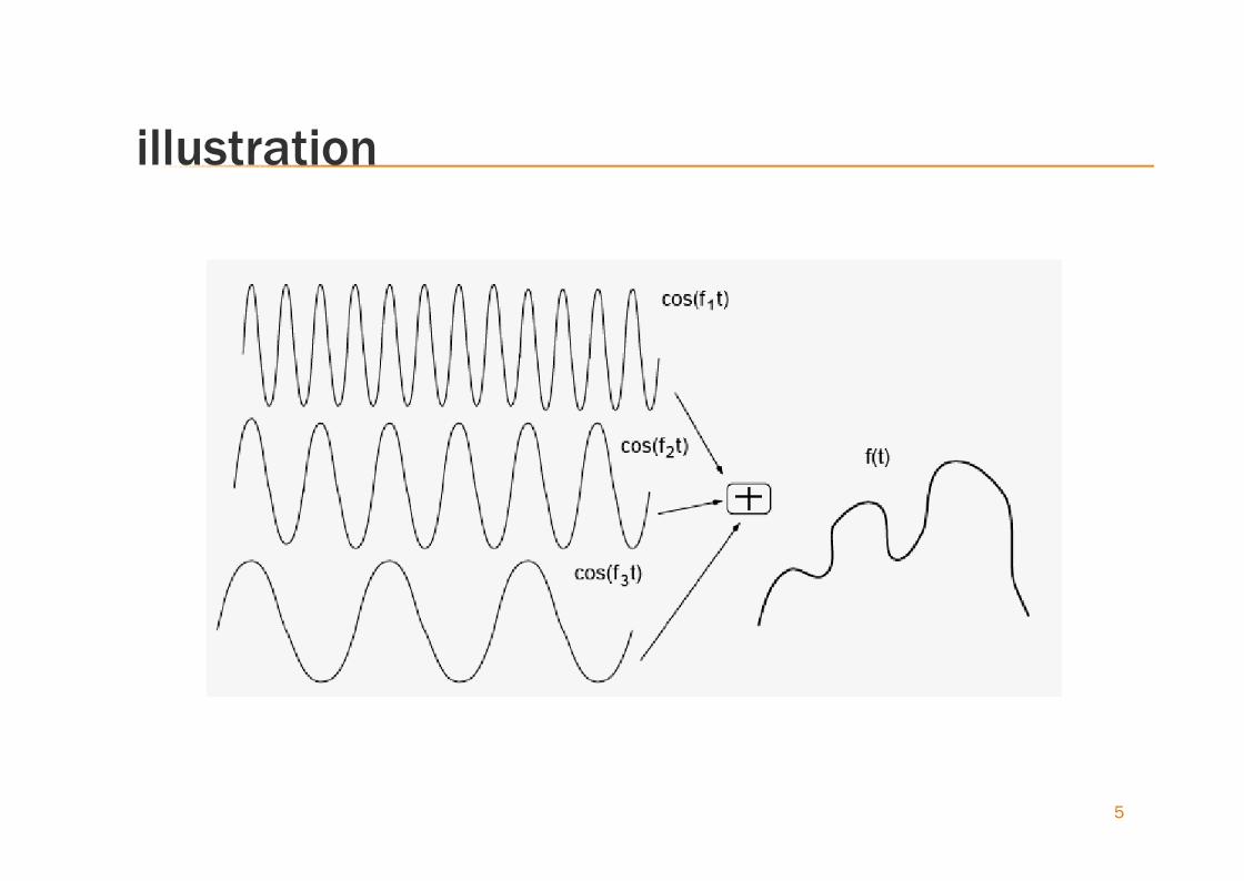
illustration
5
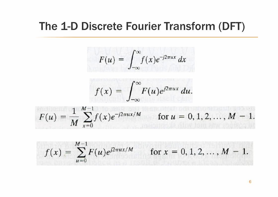
The 1-D Discrete Fourier Transform (DFT)
6

Notes
To compute F(u) we set u=0 in the exponential term
and then summing for all values of x.
Like f(x), F(u) is also discrete and has the same
number of components as f(x).
The 1/M multiplier may be placed in front of the
inverse transform instead.
7
The 1-D Discrete Fourier Transform (DFT)cont…
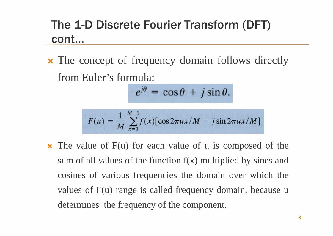
The concept of frequency domain follows directlyfrom Euler’s formula:
The value of F(u) for each value of u is composed of thesum of all values of the function f(x) multiplied by sines andcosines of various frequencies the domain over which thevalues of F(u) range is called frequency domain, because udetermines the frequency of the component.
8
Fourier Spectrum
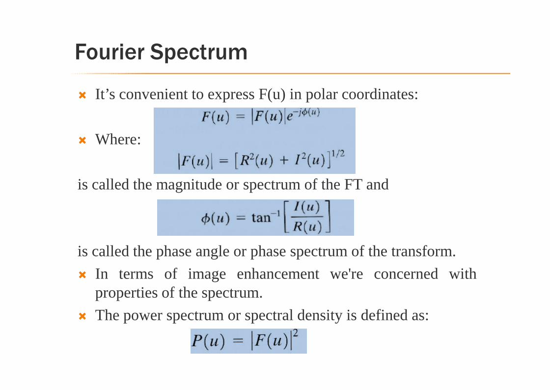
It’s convenient to express F(u) in polar coordinates:
Where:
is called the magnitude or spectrum of the FT and
is called the phase angle or phase spectrum of the transform. In terms of image enhancement we're concerned with
properties of the spectrum. The power spectrum or spectral density is defined as:
Example
10
Note:
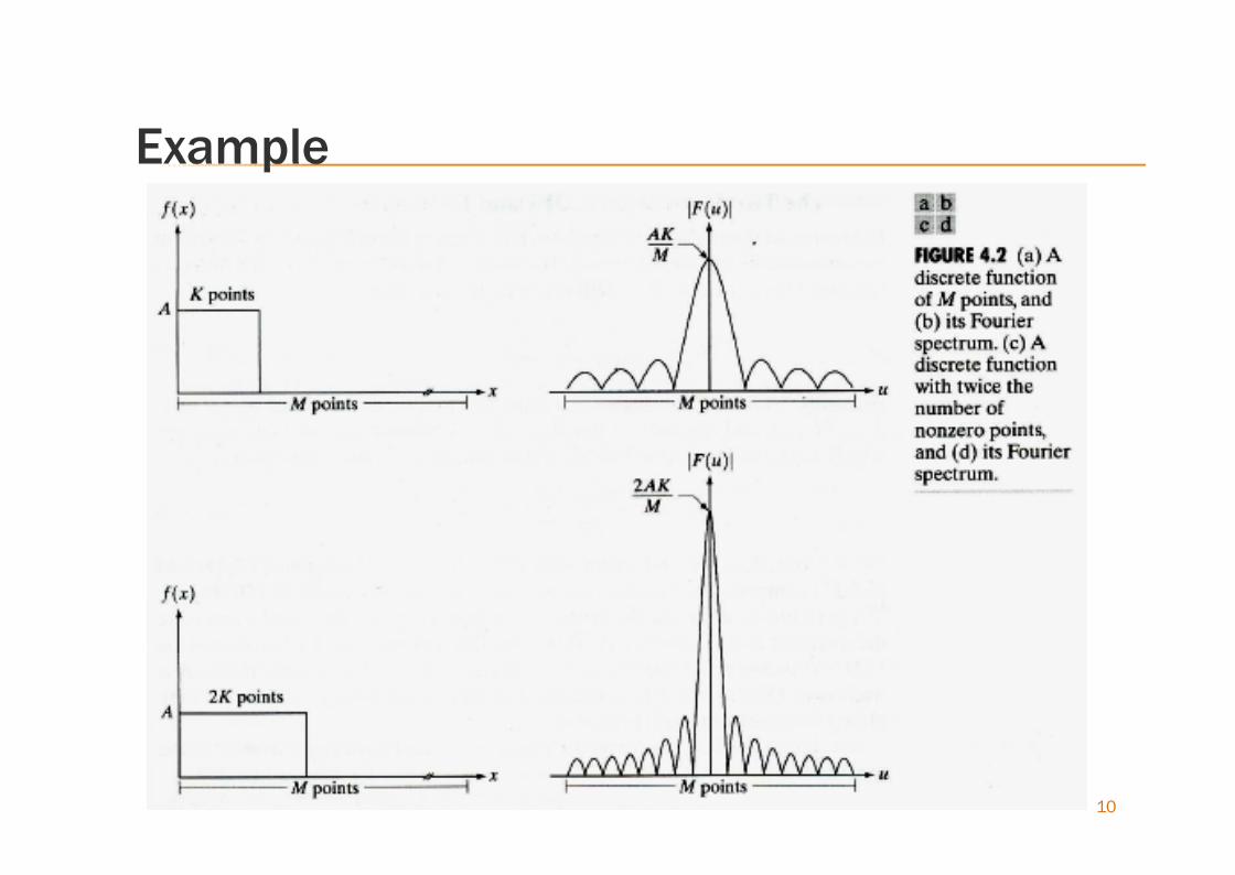
The height of the spectrum doubled as the areaunder the curve in the x-domain doubled.
The number of zeros in the spectrum in the sameinterval doubled as the length of the functiondoubled.
11
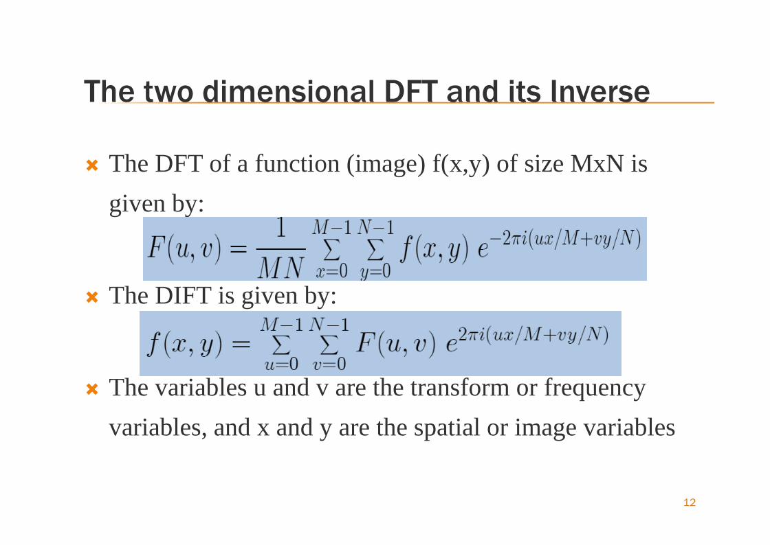
The two dimensional DFT and its Inverse
The DFT of a function (image) f(x,y) of size MxN isgiven by:
The DIFT is given by:
The variables u and v are the transform or frequencyvariables, and x and y are the spatial or image variables
12

The two dimensional DFT and its Inverse
13

Note:
Since we have
Thus multiplying f(x,y) by (-1)x+y by shifts theorigin of F(u,v) to(M/2, N/2), the center of theMxN area occupied by the 2-D DFT calledfrequency rectangle.
14

15
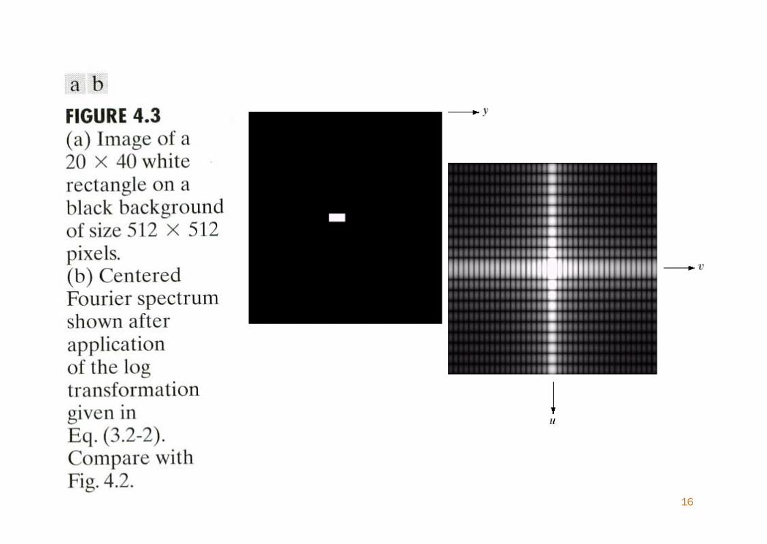
16
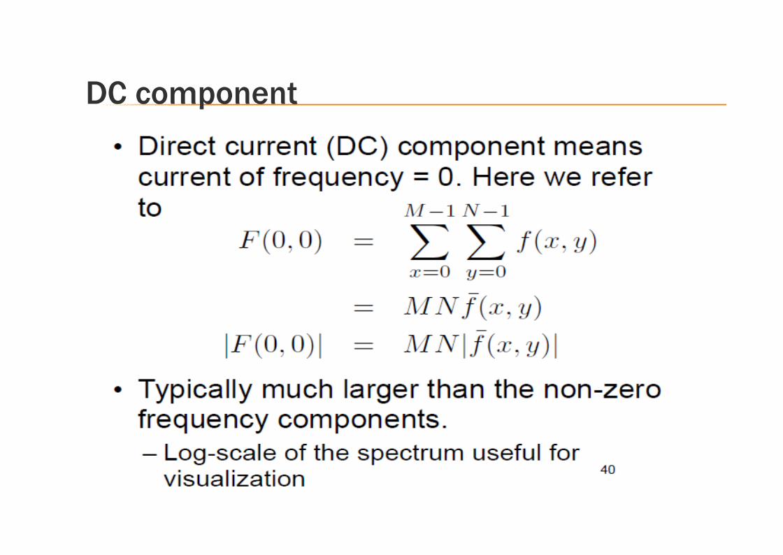
DC component
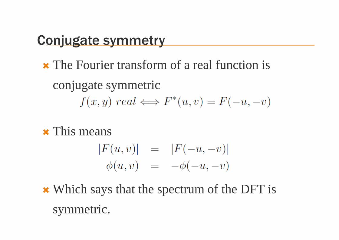
Conjugate symmetry
The Fourier transform of a real function isconjugate symmetric
This means
Which says that the spectrum of the DFT issymmetric.
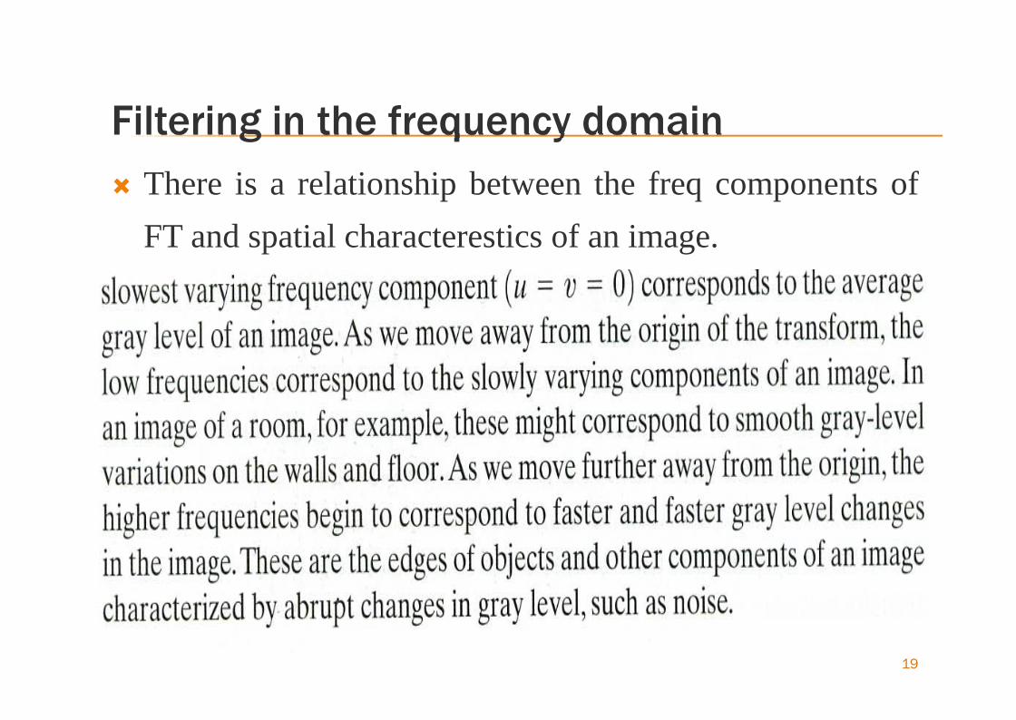
Filtering in the frequency domain There is a relationship between the freq components of
FT and spatial characterestics of an image.
19
20

Basic steps for filtering in the frequency domain
21
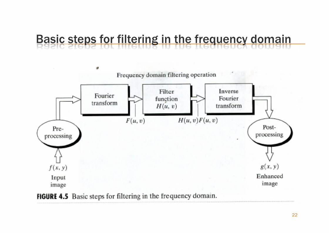
Basic steps for filtering in the frequency domain
22
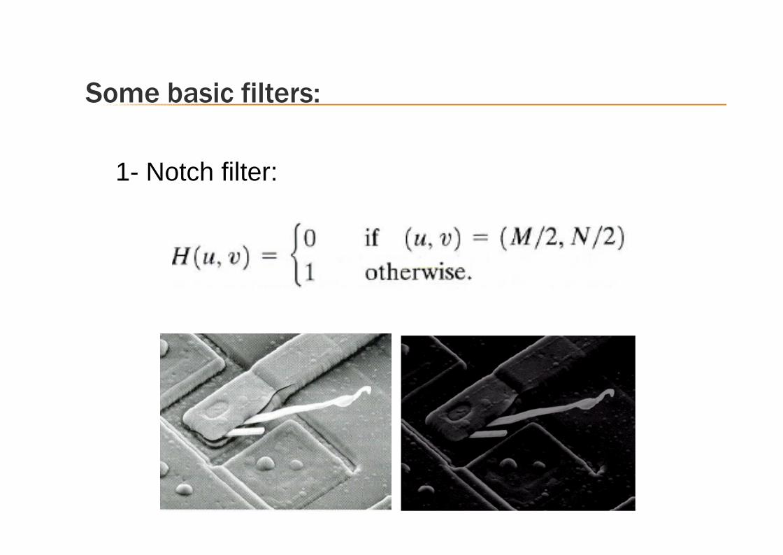
1- Notch filter:
Some basic filters:
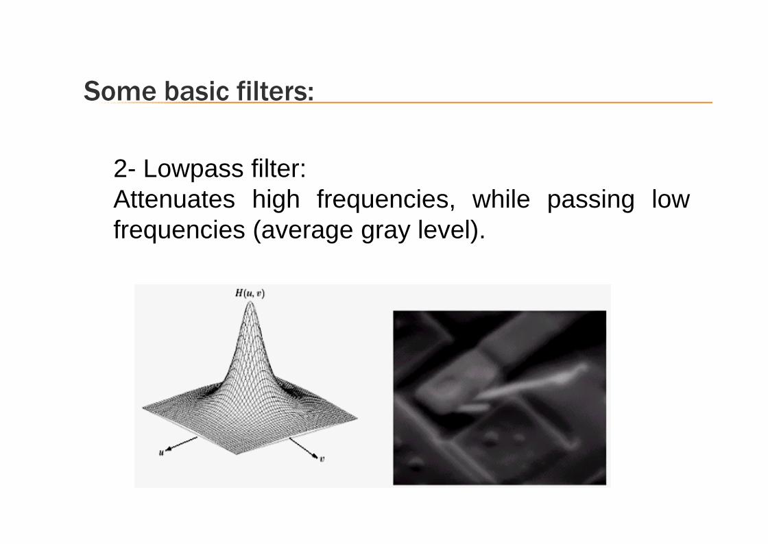
2- Lowpass filter:Attenuates high frequencies, while passing lowfrequencies (average gray level).
Some basic filters:
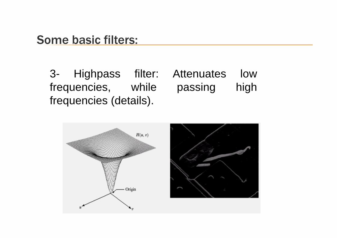
3- Highpass filter: Attenuates lowfrequencies, while passing highfrequencies (details).
Some basic filters:

Smoothing (frequency domain) filter
Edges and other sharp transitions (Noise) in an imagecontribute to the high-frequencies component of the FT.
The objective is to select a filter transfer function H(u,v)that yields G(u,v) by attenuating the high-frequencycomponents of F(u,v)
We consider three types of smoothing filters which are: Ideal Lowpass Filter (Very Sharp)
Butterworth Lowpass filter (Mid Sharp)
Gaussian Lowpass Filter (Very Smooth)
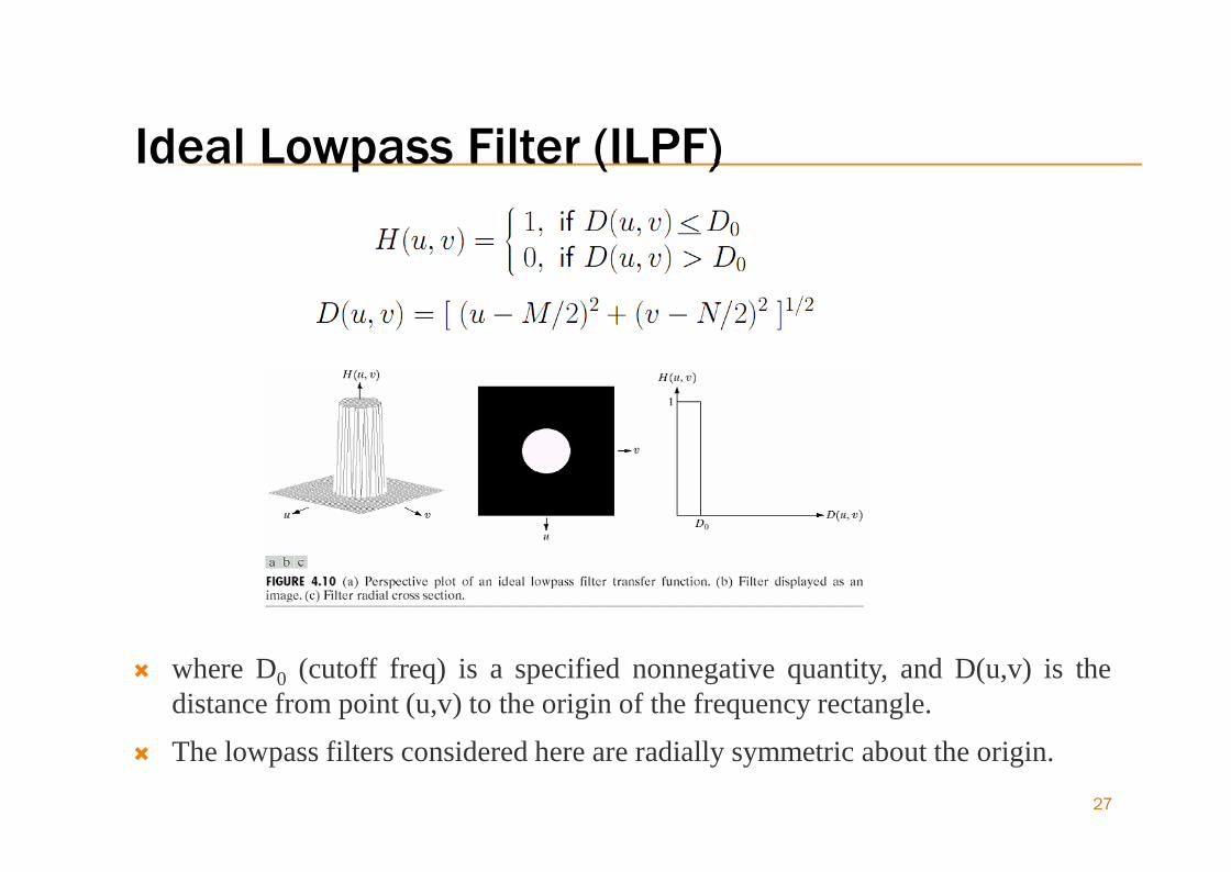
Ideal Lowpass Filter (ILPF)
27
where D0 (cutoff freq) is a specified nonnegative quantity, and D(u,v) is thedistance from point (u,v) to the origin of the frequency rectangle.
The lowpass filters considered here are radially symmetric about the origin.

ILPF cont…
Simply cut off all high frequency components that are at aspecified distance D0 from the origin of the transform
changing D0changes the behaviour of the filter.
Standard cutoff frequency for comparing filters are choosencircles that enclose specified amounts of total image power PT
The summation is taken over the values of (u,v) inside the circle
28
ILPF cont…
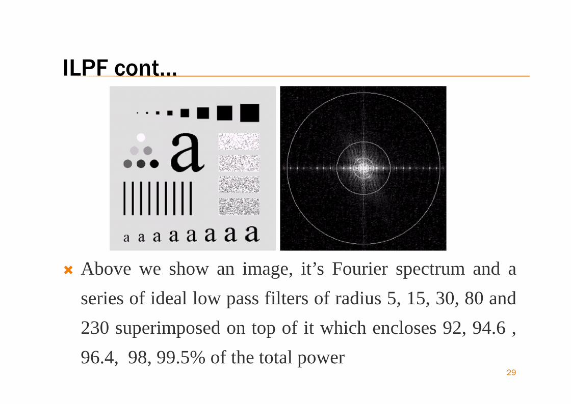
Above we show an image, it’s Fourier spectrum and aseries of ideal low pass filters of radius 5, 15, 30, 80 and230 superimposed on top of it which encloses 92, 94.6 ,96.4, 98, 99.5% of the total power
29
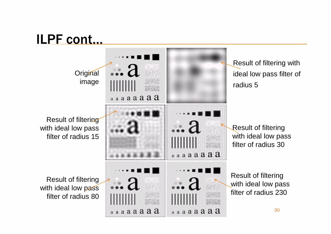
ILPF cont…
30
Originalimage
Result of filtering withideal low pass filter ofradius 5
Result of filteringwith ideal low passfilter of radius 30
Result of filteringwith ideal low passfilter of radius 230
Result of filteringwith ideal low pass
filter of radius 80
Result of filteringwith ideal low pass
filter of radius 15

ILPF and “Ringing effect”
To find h(x, y):1.Centering: H(u, v) ∗ (−1)u+v
2.Inverse Fourier transform3.Multiply real part by (−1)x+y
Properties of h(x, y):1.It has a central dominant circular
component (providing the blurring)2. It has concentric circular
components (rings) giving rise to theringing effect.
31
Example of h(x)from the inverse FTof a disc (ILPF)with radius 5.
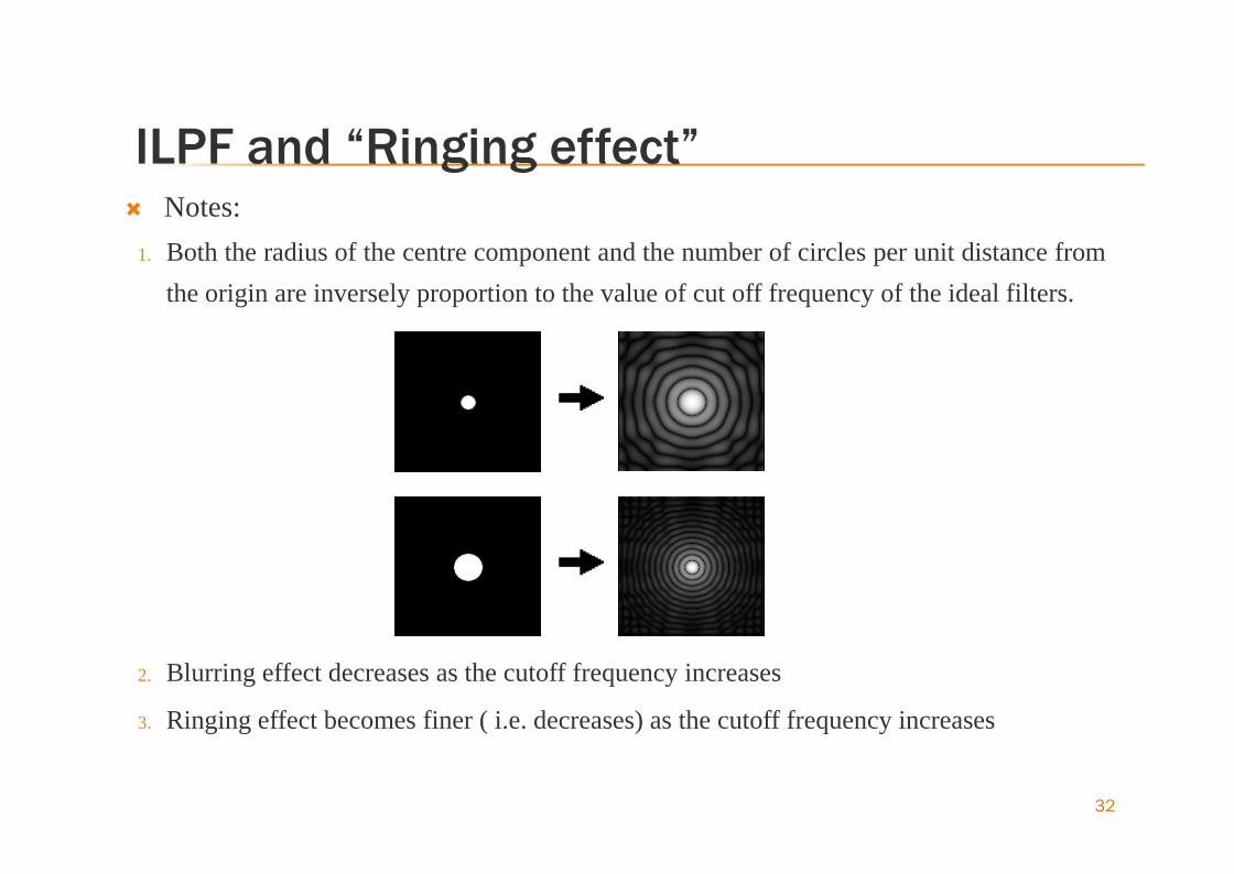
ILPF and “Ringing effect” Notes:
1. Both the radius of the centre component and the number of circles per unit distance fromthe origin are inversely proportion to the value of cut off frequency of the ideal filters.
2. Blurring effect decreases as the cutoff frequency increases
3. Ringing effect becomes finer ( i.e. decreases) as the cutoff frequency increases
32
33
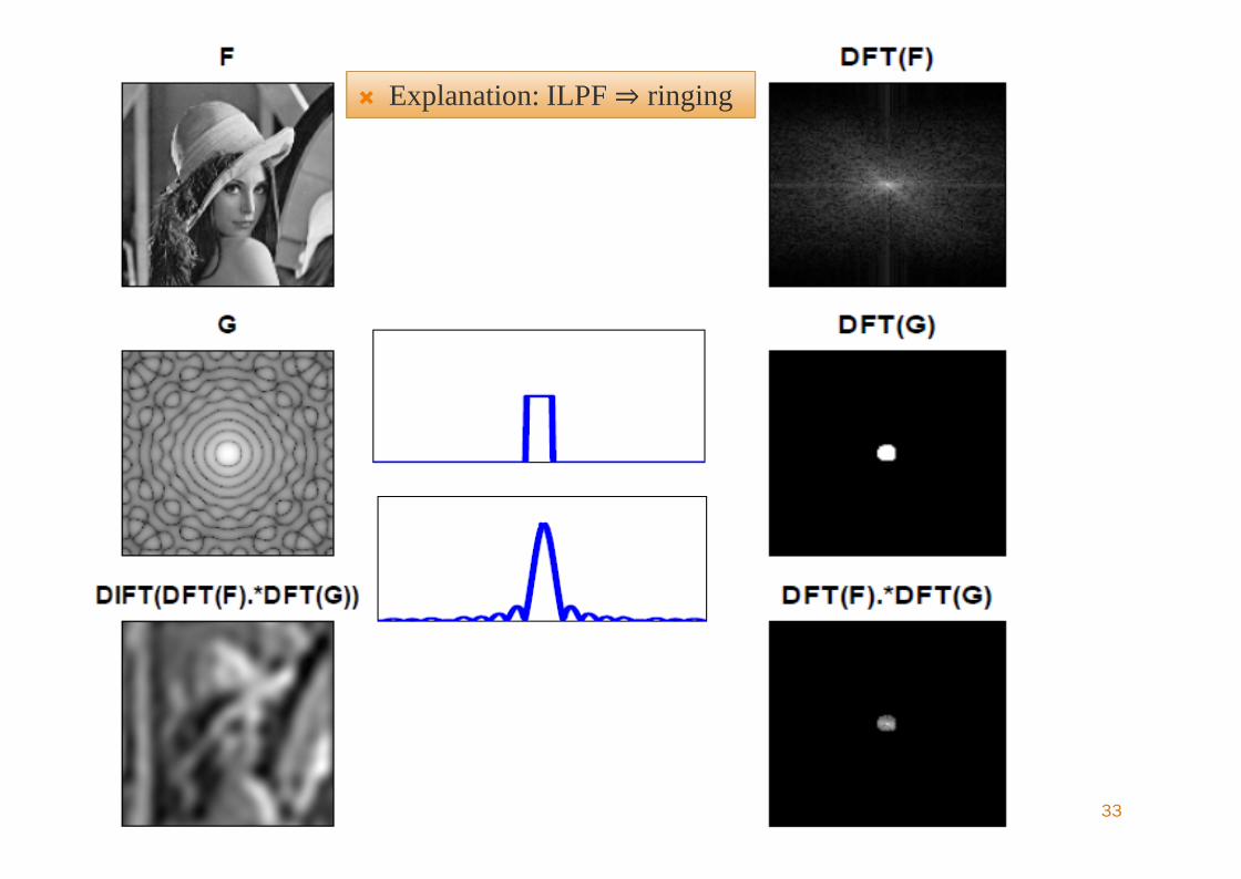
Explanation: ILPF⇒ ringing Explanation: ILPF⇒ ringing
Blurring with little or no ringing
Blurring with little or no ringing requires gentlerways of cutting off high frequencies. Butterworth low pass filter(BLPF)
Gaussian low pass filter(GLPF)
The goals of these and similar filters is to cut offthe high frequencies gradually.
34

Butterworth Lowpass Filters
35
Butterworth lowpass filter (BLPF) of order n, and with cutofffrequency at a distance D0 from the origin has the function:
A cutoff frequency is defined at points for which H(u,v) is down toa certain fraction of its maximum value In this case, H(u,v) = 0.5when D(u,v) = D0

Butterworth Lowpass Filters
36
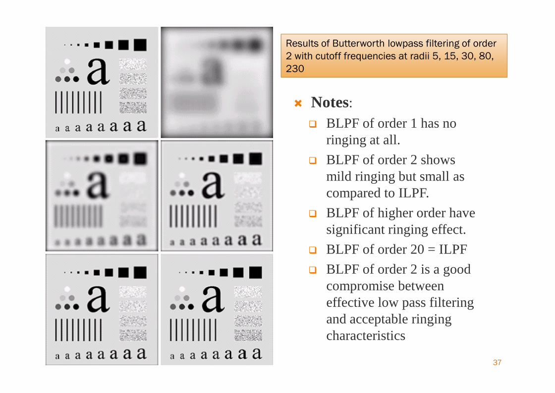
37
Notes: BLPF of order 1 has no
ringing at all. BLPF of order 2 shows
mild ringing but small ascompared to ILPF.
BLPF of higher order havesignificant ringing effect.
BLPF of order 20 = ILPF BLPF of order 2 is a good
compromise betweeneffective low pass filteringand acceptable ringingcharacteristics
Results of Butterworth lowpass filtering of order2 with cutoff frequencies at radii 5, 15, 30, 80,230
Results of Butterworth lowpass filtering of order2 with cutoff frequencies at radii 5, 15, 30, 80,230
38
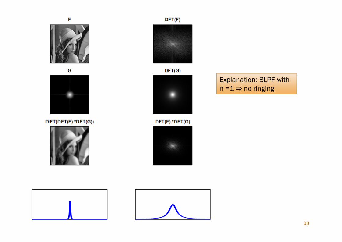
Explanation: BLPF withn =1⇒ no ringingExplanation: BLPF withn =1⇒ no ringing
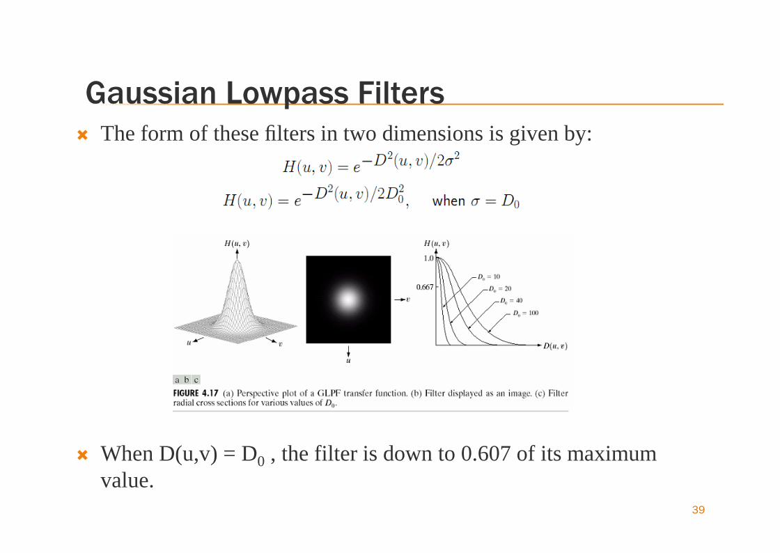
Gaussian Lowpass Filters
39
The form of these filters in two dimensions is given by:
When D(u,v) = D0 , the filter is down to 0.607 of its maximumvalue.
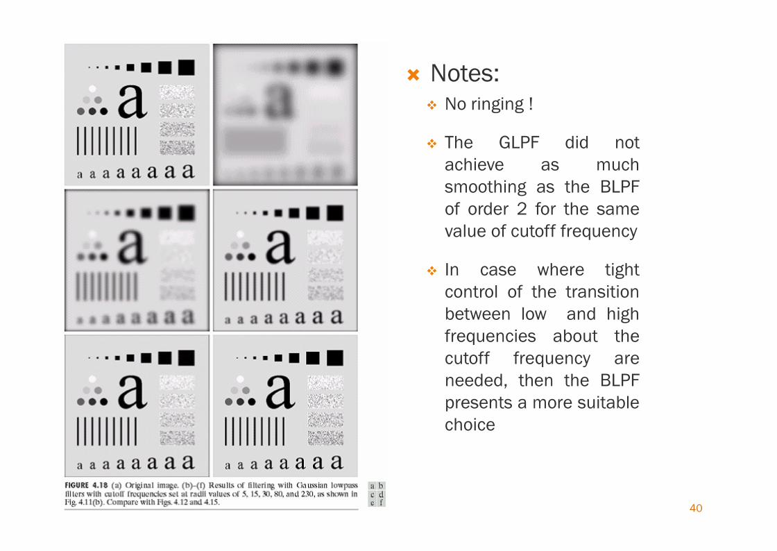
40
Notes: No ringing !
The GLPF did notachieve as muchsmoothing as the BLPFof order 2 for the samevalue of cutoff frequency
In case where tightcontrol of the transitionbetween low and highfrequencies about thecutoff frequency areneeded, then the BLPFpresents a more suitablechoice
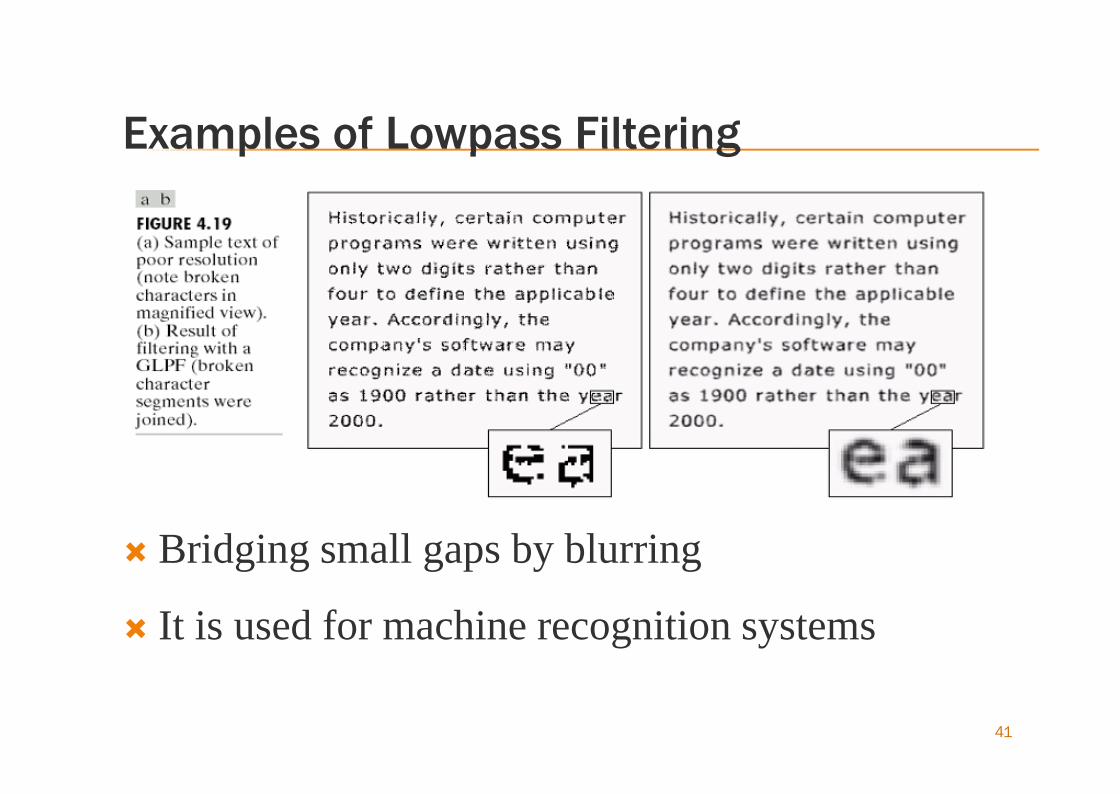
Examples of Lowpass Filtering
Bridging small gaps by blurring
It is used for machine recognition systems
41

Examples of Lowpass Filtering
Lowpass filtering is used for numerous preprocessing functions in the printingand publishing industry
“Cosmetic” processing is one of the uses prior to printing
The smoothed images look quite soft and pleasing 42

Sharpening Frequency Domain Filters Image can be blurred by attenuating the high-frequency
components of its Fourier transform.
Edges and other abrupt changes in gray levels are associated withhigh-frequency components.
We consider only zero-phase-shift filters that are radiallysymmetric.
The transfer function of the highpass filters can be obtained using
H (u,v) hp = 1- H lp (u,v)
Where H lp (u,v) is the corresponding lowpass filter
43
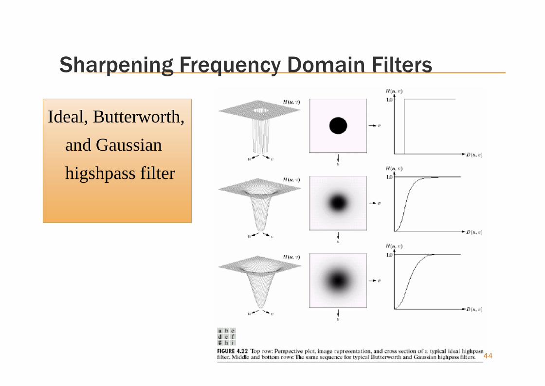
Sharpening Frequency Domain Filters
Ideal, Butterworth,and Gaussianhigshpass filter
Ideal, Butterworth,and Gaussianhigshpass filter
44

45
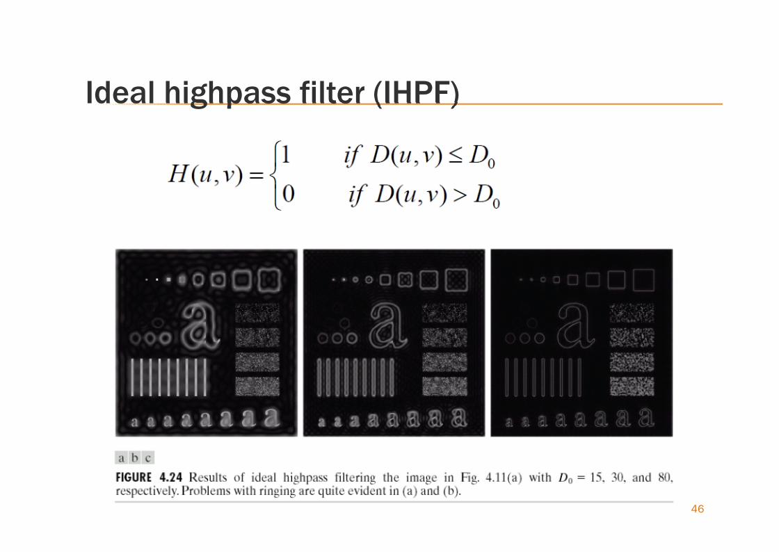
Ideal highpass filter (IHPF)
46
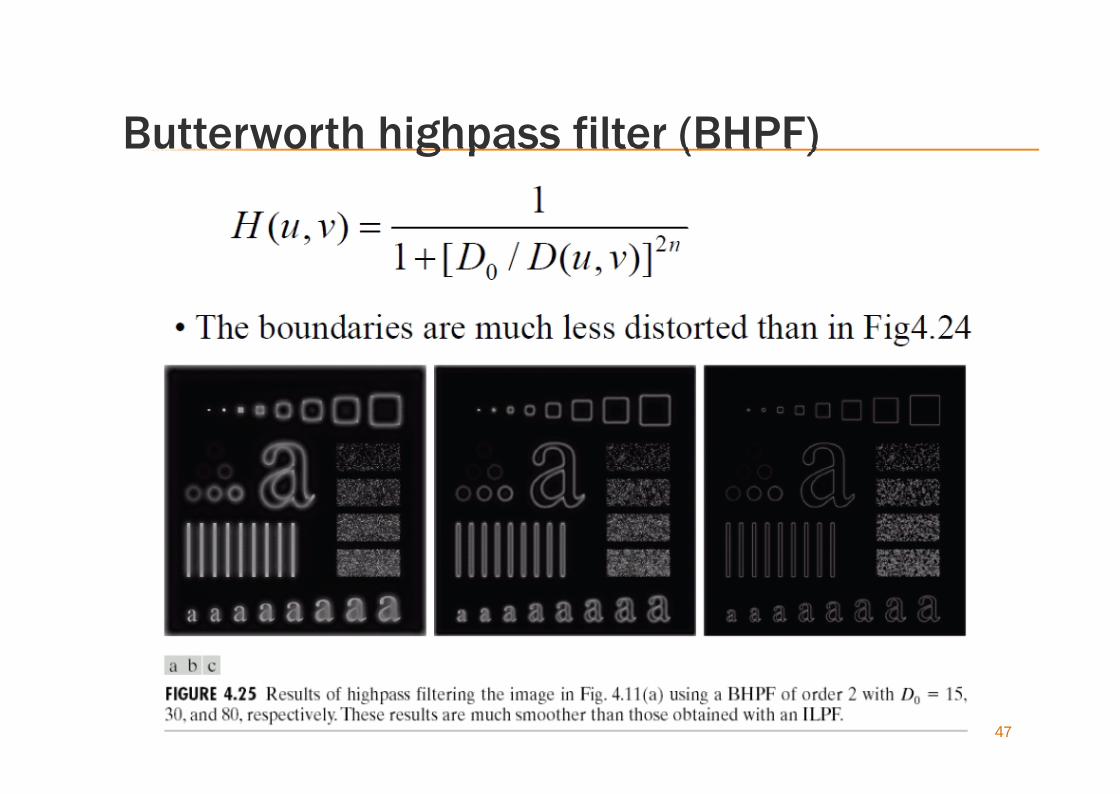
Butterworth highpass filter (BHPF)
47
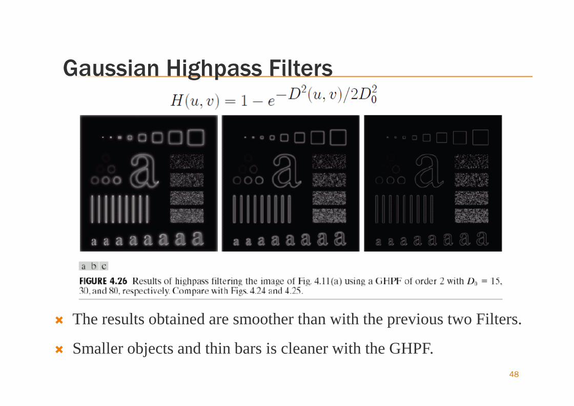
Gaussian Highpass Filters
The results obtained are smoother than with the previous two Filters.
Smaller objects and thin bars is cleaner with the GHPF.48

The Laplacian in Freq. Domain
Laplacian can be implemented in the frequencydomain by using the filter
The center of the filter function also needs to beshifted
49
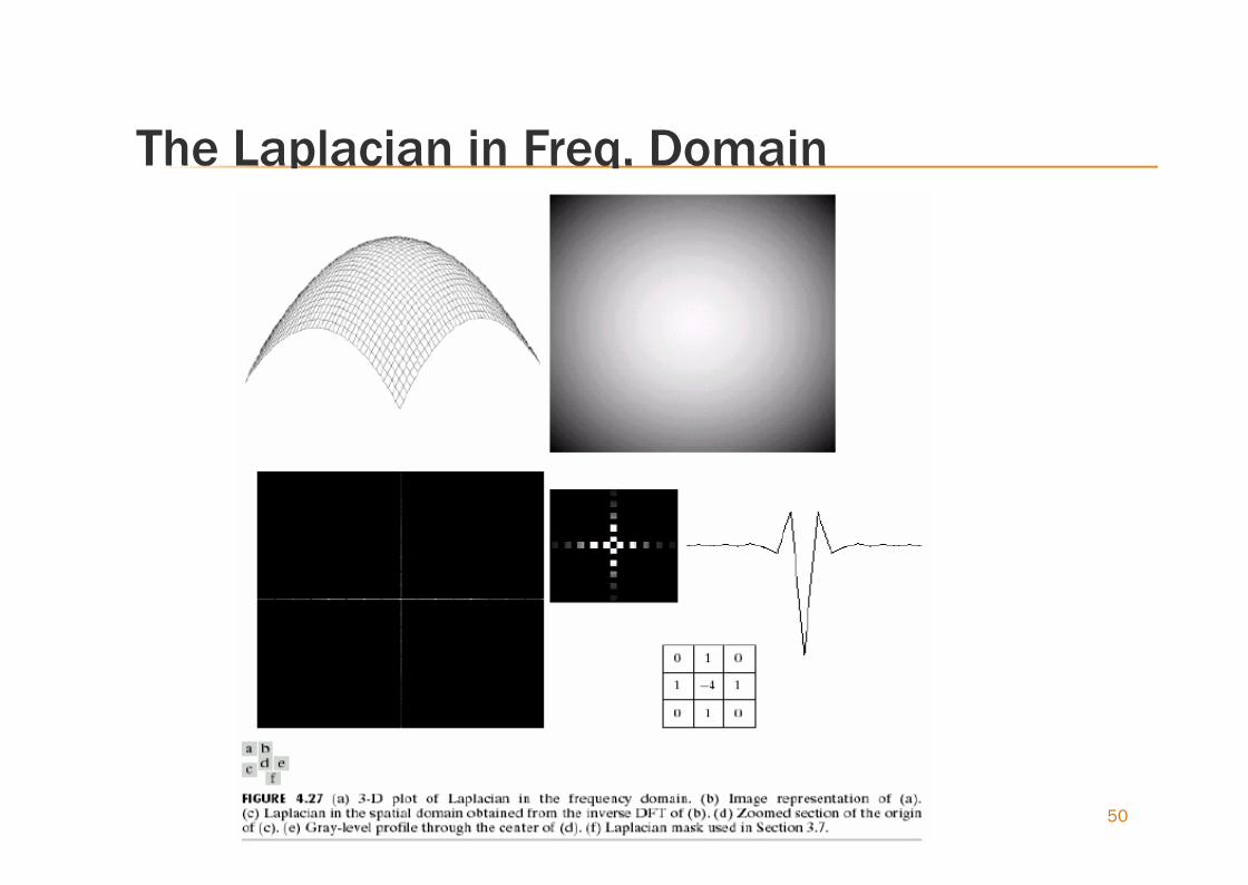
The Laplacian in Freq. Domain
50
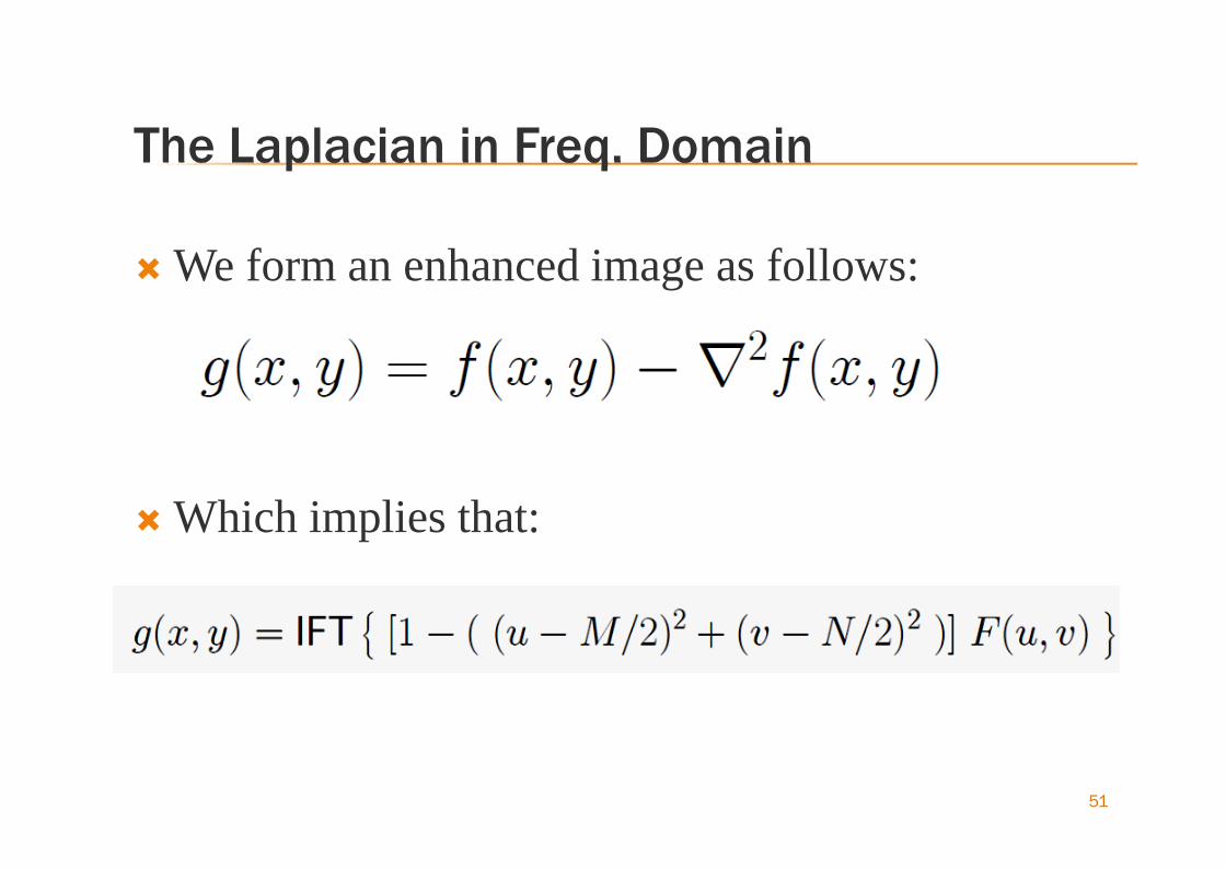
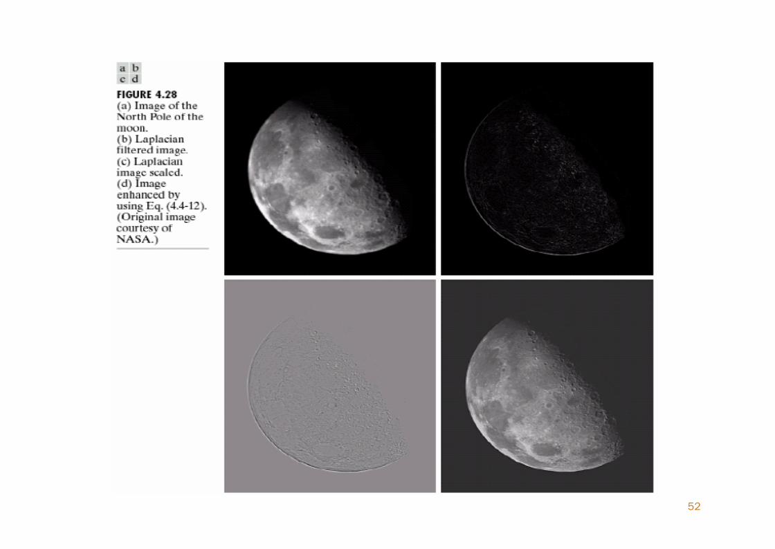
The Laplacian in Freq. Domain
We form an enhanced image as follows:
Which implies that:
51
52
High-Boost Filtering and others
Generating a sharp image by subtracting from animage a blurred version of itself.
High-boost filtering
A generalization of unsharp masking, to increasethe contribution made by the original image
53
High-Boost Filtering and others
54
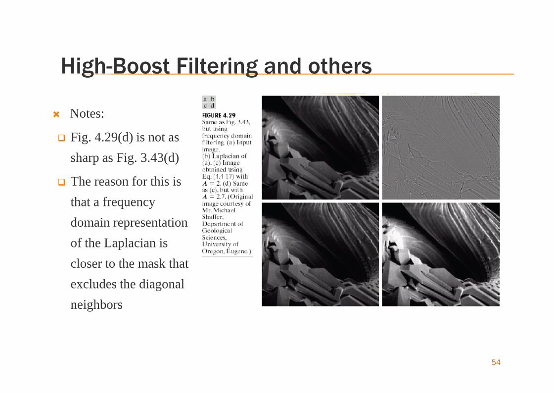
Notes:
Fig. 4.29(d) is not assharp as Fig. 3.43(d)
The reason for this isthat a frequencydomain representationof the Laplacian iscloser to the mask thatexcludes the diagonalneighbors
High-Boost Filtering and others
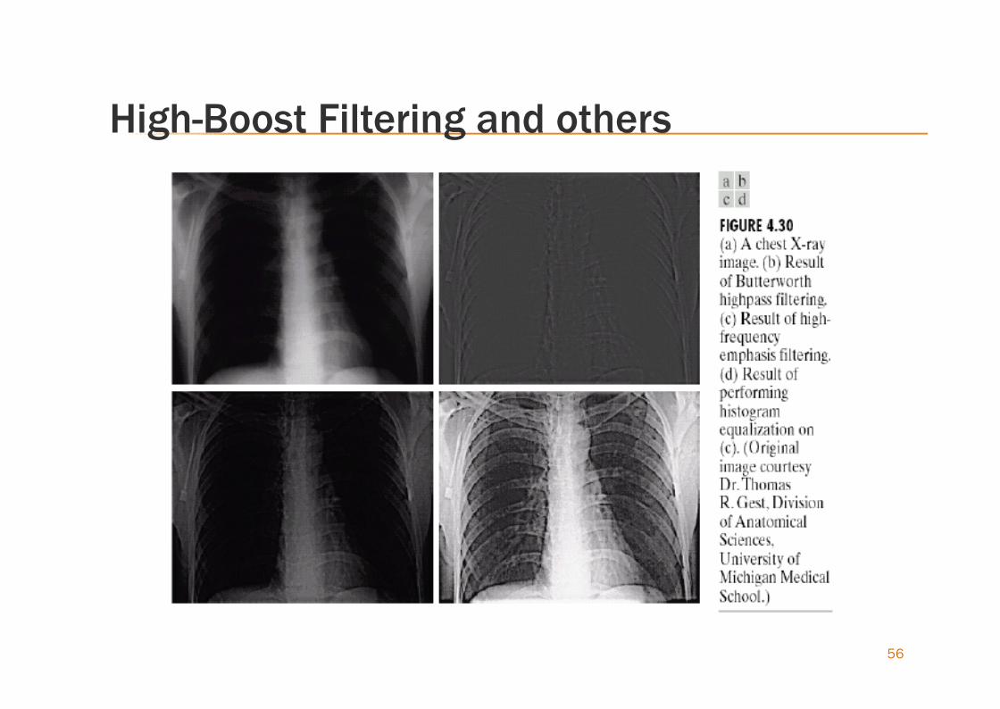
High-frequency emphasis It is advantageous to accentuate the contribution to enhancement
made by the high-frequency components of an image.
We simply multiply a highpass filter function by a constant andadd an offset so that the zero frequency term is not eliminated bythe filter
Typical values of a are in the range 0.25 to 0.5 and b in the rangeof 1.5 to 2.0
55
High-Boost Filtering and others
56


