EET101 LITAR ELEKTRIK 1 ELECTRIC CIRCUIT 1 SEM 1 2008 09 Lecturer : Wan Nur Suryani Firuz Bt Wan Ariffin Office: KKF 8C Email : [email protected]Reference Book: 1. Fundamentals of Electric Circuits – Alexander sadiku (3 rd edition) 2. Electric Circuits Fundamentals – FLOYD (7 Th edition)
Chap 1 : Circuit Elements and VariablesOverview of circuit analysis, SI unit, voltage and currents, power, energy, elements on the circuit (passive and active) voltage and current source, Ohm’s Law, Kirchhoff’s Law, circuit model, circuit with dependent source. Chap 2 : Resistive CircuitSeries / Parallel circuit, voltage divider circuit, current divider circuit, voltage and current measurement, Wheatstone Bridge, equivalent circuit for delta-wye (Pi-Tee).
Chap 3 : Circuit Analysis Methods Introduction to the Node-Voltage Method, the Node-Voltage Method with dependent sources and special cases, introduction to Mesh-Current Method, Mesh-Current Method with dependent sources and special cases, source transformations, Thevenin and Norton equivalent circuit, maximum power transfer and superposition. Chap 4 : Inductance and CapacitanceInductor, relationship between voltage, current, power and energy, capacitor, relationship between voltage, current, power and energy, series-parallel combinations for inductance and capacitance.
Chap 5 : First-Order and Second-Order Response of RL and RC Circuit Natural response of RL and RC Circuit, Step Response of RL and RC Circuit, general solutions for natural and step response, sequential switching, introduction to the natural and step response of RLC circuit, natural response of series and parallel RLC circuit, Step response of series and parallel RLC circuit. Chap 6: Sinusoidal Steady-State AnalysisThe sinusoidal source, the sinusoidal response, the phasor and phasor diagram, the passive circuit elements in the frequency domain, impedances and reactances, Kirchhoff’s Laws in frequency domain, techniques of circuit analysis in frequency domain Chap 7 : Sinusoidal Steady-State Power CalculationInstantanenous power, average (active) and reactive power, the rms value power calculation, complex and power triangle , the maximum power transfer Chap 8 : Three Phase System CircuitSingle and Three Phase System (Y and Δ circuit), balanced three phase voltage sources, Y – Y circuit analysis, Y - Δ circuit analysis, power calculation in three phase balanced circuit, average power measurement in three phase circuit.
Syl
lab
us
- E
ET
101
COURSE STRUCTURE
• Final Exam = 50%• Laboratory = 20%• Test (2 test) = 20%
Test 1 – 6 September 2008Test 2 – 18 October 2008
• Assignment = 10%Group & Tutorial
Total : =100%
Basic electric circuit concepts
• Review SI • Know the definition of basic electrical
quantities : voltage, current, and power• Know the symbols for and definition of
independent and dependent sources• Be able to calculate the power absorbed
by a circuit element using the passive sign convention
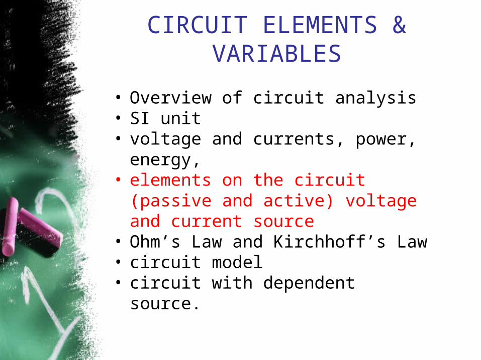
CIRCUIT ELEMENTS & VARIABLES
• Overview of circuit analysis• SI unit• Voltage,currents, power, energy, • elements on the circuit (passive
and active) voltage and current source
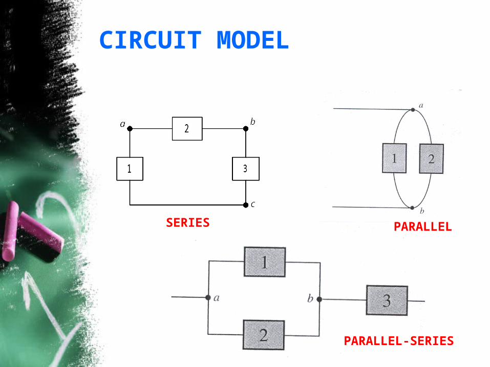
• Ohm’s Law and Kirchhoff’s Law• circuit model• circuit with dependent source.
SI UNIT• Unit SI
SI : International System of Unit is used by all the major engineering societies and most engineers throughout the world.
Quantity Base unit Symbol
Length Meter m
Mass Kilogram kg
Time second s
Electric current Ampere A
Thermodynamic temperature
Kelvin K
Luminousintensity
candela cd
• Standardized prefixes to signify powers of 10
Power Prefix Symbol
1012 Tera T
109 Giga G
106 Mega M
103 Kilo k
100
10-3 Mili m
10-6 Micro µ
10-9 Nano n
10-12 Pico p
10-15 Femto f
10-18 Atto a
CIRCUIT ELEMENTS & VARIABLES
• Overview of circuit analysis• SI unit• Voltage, currents, power, energy, • elements on the circuit (passive
and active) voltage and current source
• Ohm’s Law and Kirchhoff’s Law• circuit model• circuit with dependent source.
ELECTRIC UNITS
• Charge »»» Coulomb (C)• Current »»» Ampere (A)• Voltage »»» Volt (V)• Resistance »»» Ohm ()• Power »»» Watt (W)
Electric charge is a property possessed by both electrons and protons.
Quantity is
CHARGE (Q)
COULOMB (C)Base Unit is
Examples of correct usage:
Charge = 15 Coulombs
Q = 15 C
Current is the movement of charge in a specified direction.
CURRENT
Electric Current Terminology
Quantity is CURRENT (I)
AMPERE (A)Base Unit is
Examples of correct usage:Current = 12 Amperes
I = 12 A
An ampere equals a coulomb per second.
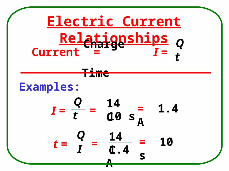
Electric Current Relationships
Current = I =
Examples:
Charge Time
Qt
I = Qt =
14 C 10 s
= 1.4 A
t = QI =
14 C 1.4 A
= 10 s
Types of current:i
t
i
t
Direct current (arus terus)Alternating current
(arus ulangalik)
Damped alternating current(arus ulangalik teredam) Exponential current
ACDC
ex: Used to run
refrigerator,
stove, washing
machine, and so
on…
ex batteries – used in
automobiles or flashlight
• Voltage is the electric pressure or force that causes current.
• It is a potential energy difference between two points.
• It is also known as an electromotive force (emf) or potential.
Definition of Voltage
VOLTAGE
Voltage Terminology
Quantity is VOLTAGE (V)
VOLT (V)Base Unit is
Examples of correct usage:Voltage = 32 Volts
V = 32 V
A volt equals a joule per coulomb.
Voltage Relationships
Voltage = V =
Examples:
EnergyCharge
WQ
V = WQ =
56 J 2 C
= 28 V
Q = WV =
84 J 21 V
= 4 C
Resistance is the oppositiona material offers to current.
Resistance is determined by:
• Type of material (resistivity)
• Temperature of material
• Cross-sectional area
• Length of material
Definition of Resistance
RESISTANCE
Some Factors That Determine Resistance
For a specific material and temperature, this block has given amount of resistance.
Doubling the length of the block, Doubling the cross-sectional area,
doubles the resistance.halves the resistance.
Resistance Terminology
Quantity is RESISTANCE (R)
OHM ()Base Unit is
Examples of correct usage:
Resistance = 47 ohmsR = 47
An ohm equals a volt per ampere.
Resistance Relationships
Resistance = R =
Example:
Resistivity x length area
KLA
R = KLA
=
= 0.1
1.4 x10-6 cm x 2 x104 cm 0.28 cm2
Work (W)consists of a force moving through a distance.
Energy (W)is the capacity to do work.
The joule (J)is the base unit for both energy and work.
The amount of work done equals the amount of
energy used (converted).
Fifty joules of energy are
required to do fifty joules of
work.
ENERGY
Power is the rate of using energy or doing work.
“Using energy” means that energy is being converted to a different form.
Definition of Power
POWER
Power Terminology
Quantity is POWER (P)
WATT (W)Base Unit is
Examples of correct usage:
Power = 120 Watts
P = 120 W
A watt equals a joule per second.
Power Relationships
Power = P =
Examples:
Energy Time
W t
P = W t =
158 J 20 s
= 7.9 W
W = Pt = 75 W x 25 s = 1875 J
CIRCUIT ELEMENTS & VARIABLES
• Overview of circuit analysis• SI unit• voltage and currents, power,
energy, • elements on the circuit (passive
and active) voltage and current source
• Ohm’s Law and Kirchhoff’s Law• circuit model• circuit with dependent source.
ACTIVE AND PASSIVE ELEMENTS
Circuit Elements
Active elements•capable of generating electric energy•Example : voltage and current sources
Passive elements•incapable of generating electric energy•Example : resistore, inductor, capacitor, diode and etc
Independent source
Voltage
Current
Dependent source
xs iV xs Vi
Voltage Current
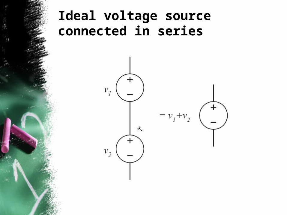
Ideal voltage source connected in series
Ideal current source connected in parallel
Symbol of circuit elements
• Resistor
RUNIT: Ohm (Ω)
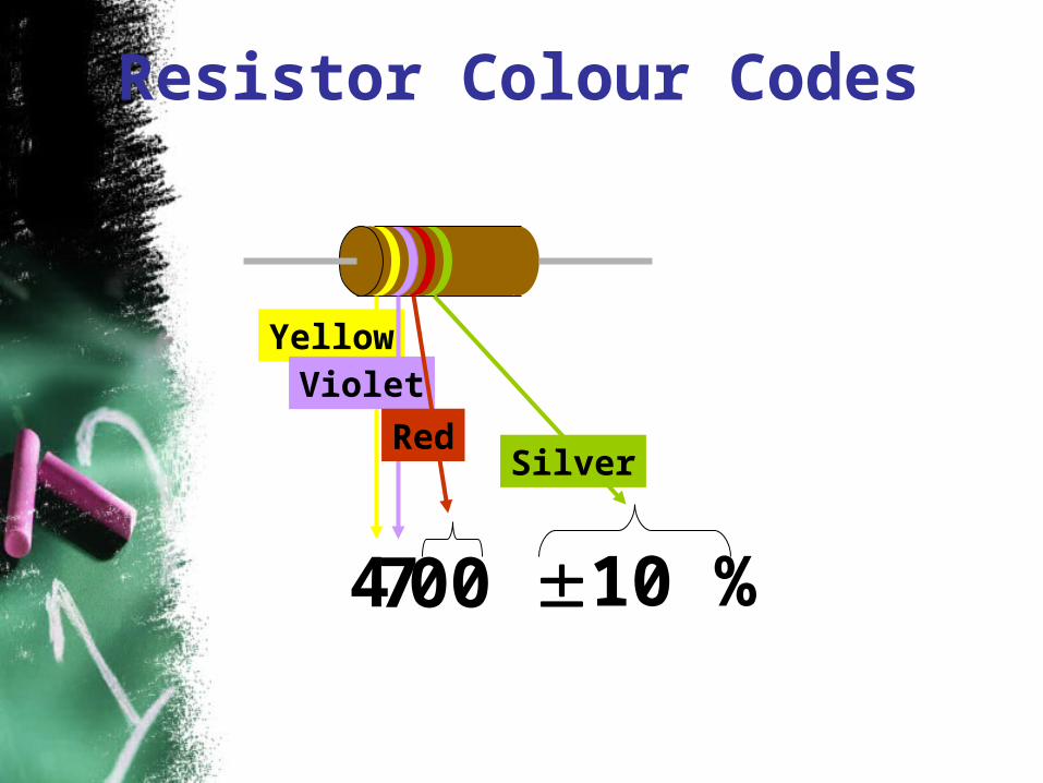
Resistor colour code
Resistor Colour Codes
Yellow
4 10 %
Silver
7
Violet
00
Red
Resistor Colour Codes
Green = 5 Blue = 6 Orange = 3 Gold = 5 %
56 x 103 5 % =56000 5 % = 56 k 5 %
Resistor Colour Codes
4 0 0 06 4 2% = 464 k 2%
Conductance
• Conductance is a measure of the ability of an element to conduct electric current
• Inverse of resistance• Units: Siemens (S) or mhos
v
i
R
1G
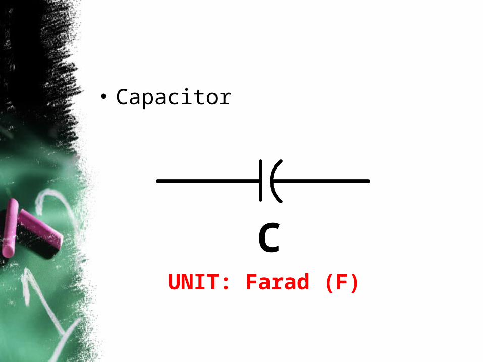
• Capacitor
CUNIT: Farad (F)
• Inductor
LUNIT: Henry (H)
CIRCUIT ELEMENTS & VARIABLES
• Overview of circuit analysis• SI unit• voltage and currents, power,
energy, • elements on the circuit (passive
and active) voltage and current source
• Ohm’s Law and Kirchhoff’s Law• circuit model• circuit with dependent source.
Short Circuit– R = 0 no voltage difference exists – all points on the wire are at the same
potential.– Current can flow, as determined by
the circuit
Open circuit
– R = no current flows– Voltage difference can exist, as
determined by the circuit
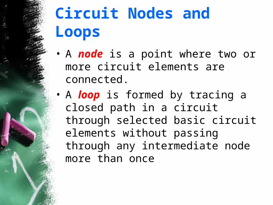
Circuit Nodes and Loops
• A node is a point where two or more circuit elements are connected.
• A loop is formed by tracing a closed path in a circuit through selected basic circuit elements without passing through any intermediate node more than once
Example: Find the Nodes
+
-Vs
node
Example: Find the loops
loop
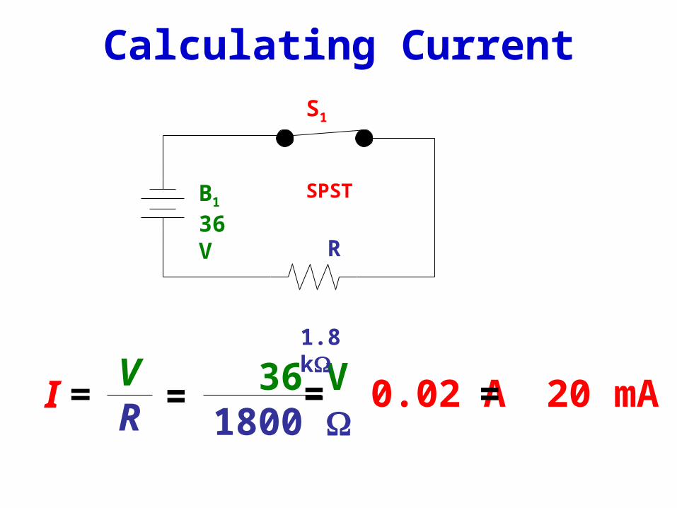
OHM LAW
• George Simon Ohm (1787-1854) formulated the relationships among voltage, current, and resistance as follows:
The current in a circuit is directly proportional to the applied voltage and inversely proportional to the resistance of the circuit.
IRV
KIRCHHOFF LAW
• Gustav Robert Kirchhoff (1824 – 1887)
• Models relationship between:– circuit element currents (KCL)– circuit element voltages (KVL)
• Introduce two laws:– Kirchhoff Current Law (KCL)– Kirchhoff Voltage Law (KVL)