28
Justin Bessette Manager of Software Electrical Engineering Community Chris Townsend Manager of Embedded Systems
| Date post: | 19-Mar-2016 |
| Category: |
Documents |
| Upload: | eeweb-magazines |
| View: | 232 times |
| Download: | 2 times |

Justin Bessette Manager of Software
Electrical Engineering Community
Chris Townsend Manager of
Embedded Systems

concepts to reality Bringing your
is as easy as...
Copyright ©2013 Aspen Labs LLC.
Visit: digikey.com/schemeit • partsim.com • pcbweb.com
1.
Create schematics, technical diagrams, and flowcharts using your browser.
• 600+ Symbol Library• Share Schematics Online• Export High Quality Images
digikey.com/schemeit
2.
Free and easy-to-use circuit simulator that runs in your browser.
• SPICE Simulator• AC/DC/Transient Sims• Waveform Viewer
partsim.com
3.
Full featured online CAD application for designing and manufacturing electronics hardware.
• Schematic Capture• PCB Layout• BOM Integration
pcbweb.com
3Visit: eeweb.com
CONTENTS
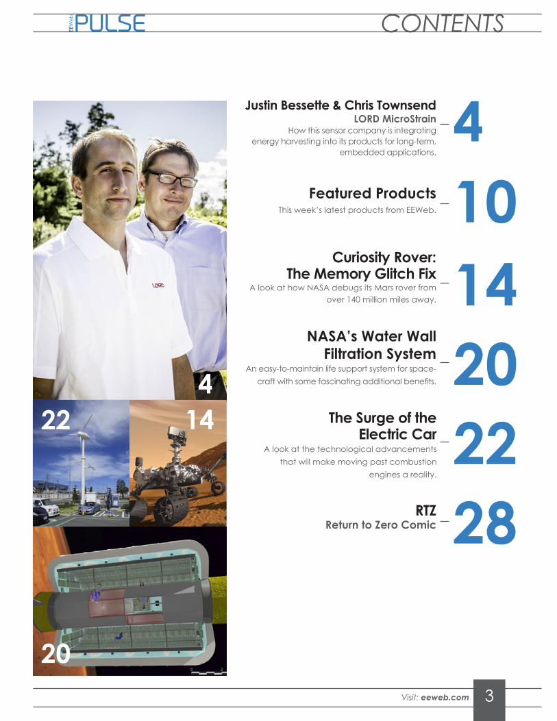
4Justin Bessette & Chris TownsendLORD MicroStrain
How this sensor company is integrating energy harvesting into its products for long-term,
embedded applications.
1014
Curiosity Rover: The Memory Glitch Fix
A look at how NASA debugs its Mars rover from over 140 million miles away.
20NASA’s Water Wall
Filtration SystemAn easy-to-maintain life support system for space-
craft with some fascinating additional benefits.
22The Surge of the
Electric CarA look at the technological advancements
that will make moving past combustion engines a reality.
20
224
PULSE
Featured ProductsThis week’s latest products from EEWeb.
RTZReturn to Zero Comic 28
14

4 Visit: eeweb.com
PULSE
LORD Microstrain is the sensing systems division of LORD Corporation, a diversified technology company headquartered in Cary, North Carolina. This Vermont-based division specializes in developing miniature, high-performance sensing systems including inertial solutions, displacement sensors, and wireless sensor networks for test and measurement. The company strives to provide advanced sensing technology that will enable the next generation of smarter and safer machines and implanted devices.
We spoke with Chris Townsend, Manager of Embedded Systems, and Justin Bessette, Manager of Software, about the wealth of opportunities in the sensing industries, their SensorCloud data platform, and how they are integrating energy harvesting into their products for more reliable and energy-efficient results.

5Visit: eeweb.com
INTERVIEW
LORD Microstrain is the sensing systems division of LORD Corporation, a diversified technology company headquartered in Cary, North Carolina. This Vermont-based division specializes in developing miniature, high-performance sensing systems including inertial solutions, displacement sensors, and wireless sensor networks for test and measurement. The company strives to provide advanced sensing technology that will enable the next generation of smarter and safer machines and implanted devices.
We spoke with Chris Townsend, Manager of Embedded Systems, and Justin Bessette, Manager of Software, about the wealth of opportunities in the sensing industries, their SensorCloud data platform, and how they are integrating energy harvesting into their products for more reliable and energy-efficient results.
S

6 Visit: eeweb.com
PULSE
What is the current wireless sensing technology that you have?
CHRIS TOWNSEND: Supplying power is a critical parameter of any wireless sensor application. There are a number of different methods. One of them—in some applications—is that you can actually power a wireless sensor by plugging it into a wall. That’s not a very demanding application. What you are really doing in that case is relying on running wires back to a central point. When you start looking at applications where you are actually embedding sensing capabilities in platforms that are moving or mobile, tethered wires are not feasible. Local, battery-powered solutions enable truly wireless systems. However, batteries ultimately require recharging or replacement in permanent applications. Another solution for powering embedded sensing systems is energy harvesting. What energy harvesting allows you to do is to collect ambient energy and convert it into electrical energy that can power your system.
Combining energy harvesting with wireless sensing eliminates any type of battery maintenance requirement and basically enables a completely autonomous, self-recording measurement system that allows a part that may have previously not reported on its health at all become a “smart” part and report this kind of information. It’s completely autonomous because it doesn’t require external power. There are a number of different technologies that we embed in with our wireless sensor components that allow you to harvest power. We use piezoelectric material that convert strain energy or vibration energy into power for wireless sensors. In the past we have used indoor solar technology
for harvesting light and providing power, very similar to the calculator that we’ve all used for 20 years. What’s happening with wireless sensors is that they require less and less power. This enables the use of energy harvesting to power these sensors and enables long-term embedment of measurement systems into different components.
Does LORD MicroStrain develop energy harvesting devices, or are you integrating solutions from other manufacturers?
CT: We do both. In some cases, we developed our own energy harvesting solutions, but in most cases, we actually integrate other manufacturer’s energy harvesting solutions in with our wireless sensors. To make an energy harvesting wireless sensor system work, you have to design the wireless sensor to be compatible with the energy that’s being produced by the environment. It’s a very closely coupled design.
Is energy harvesting becoming the industry standard?
CT: Energy harvesting is a very compelling technology for applications where ambient power is plentiful and the consumption of the sensor is demanding. However, we are equally focused on developing low-power, battery powered solutions that provide many years of continuous use without battery maintenance. The two initiatives are not exclusive. Driving the power requirements of remote sensors lower benefits every application because you can derive more useful-life, more capabilities, or smaller, more embeddable devices.
“ We’re unique in that we provide an end-to-end sensing solution from the wireless node to delivering processed data to the user.”

7Visit: eeweb.com
INTERVIEWOnce you power the system indefinitely, how do you handle all the data being generated?
CT: The ultimate performance of embedded measurement systems depends on how you get information back to the user. Software plays an integral role in this process. We’ve developed a platform for our customers called SensorCloud, which is a web-based platform our wireless sensors report to through our wireless data aggregator, or WSDA®. SensorCloud provides scalable visualization and storage technology for big sensor data. What sets SensorCloud apart is how it uses cloud data processing to automatically analyze and report on sensor data. The result is real-time indications about component health and condition.
JUSTIN BESSETTE: Our SensorCloud system is kind of a clearing house or data base to store all of this data. All of this information is going up to a cloud-based system, so what do you do with it? You can view it in history and you can go back and see events, but that’s not all that useful, especially when you want to get into automated machine monitoring. We have another service what we call MathEngine, which is a cloud-integrated scripting program that you can select pre-populated or write write algorithms and schedule them to be automated. Say you want to take an FFT. It’s as easy as highlighting the FFT channel on your sensor data, and scheduling it to happen, say once a day. If that calculation comes out and there is something that is out of spec or something has begun vibrating differently, you can report that in a message or e-mail or webpage to say what happened and when it occured. It completely removes the need for someone to care-take the data. The person that’s responsible for maintaining the system just needs to know if it’s good or bad and why. SensorCloud automates this, and without human interaction.
How do you typically connect in an application to the network?
CT: The main physical connections are either Ethernet connections at the base station or for remote applications where it may not be the Ethernet or some type of GSM or other local cellphone interface—cellular, satellite, or whatever you might have. There are applications like oil pipelines that might have cell service, so you might have something like a satellite modem for reporting.
If someone is designing a product and incorporating a larger part of your system as a subsystem in a larger role, is there the ability to access that data in an application that the customer has developed?
CT: That’s exactly right. That’s one of the reasons for the development of the MathEngine scripting language. What it allows customers to do is have a platform that facilitates data collection. Then, once that data is collected, it allows our customers to take their knowledge and apply their domain expertise in their field so that they can program whatever their failure mechanism is and use the MathEngine to develop their own algorithm. We also provide the ability to skim the website to basically look like the customer’s website. We find a third-party service that really is a platform that the party can take advantage of.
JB: We also have an application, an API, that allows the users to use our database however they wish—they can add data or access the data at the data level. That API allows the programmer to build websites or programs or whatever they wish using our data.
Could you go over some of the sensor products that you currently have?
CT: From a wireless sensing perspective, we support just about any sensor. Natively, we will have nodes that will support common temperature sensors like RTDs or thermocouples. We have a wireless sensor that will measure power and voltage for industrial equipment.
Screenshot of MathEngine E-mail Alert

8 Visit: eeweb.com
PULSE
We have sensors that will interface directly with pressure sensors, load cells, strain gauges, and accelerometers. We also have wireless sensors that are compatible with common environmental measurements like relative humidity and indoor gases like CO2 and carbon monoxide. We provide a pretty broad range of wireless sensor products. We’ve focused on building a platform where people can just start with their sensor and hook it up to a complete measurement system. We’re unique in that we provide an end-to-end sensing solution from the wireless node to delivering processed data to the user.
JB: Something that should be noted is that traditionally, when you “de-wire” sensors, they would no longer live on the same clock. This affects the synchronization between differ-ent sensors. Our LXRS® wireless network offers time-synchronized, lossless, wireless transport of the data. We have this ability to have all these wireless sensors act as if they were con-nected together in measuring and sampling on the same time scale.
CT: It’s something that you kind of take for granted when it’s wired. Essentially you have a centralized data acquisition point where you are taking all the data. With wireless sensors, they’re all mounted remotely and are operating off of different clocks. You could actually lose synchronization. That’s actually an issue for data acquisition in general. We’ve developed a time-synchronized protocol that allows all of these sensors to be synchronized in time.
So you must have some kind of coordination between all of your sensor acquisition systems?
CT: Right. There’s essentially time synchronization calibration that is go-ing on continuously in the background so they’re all kind of constantly aligning their clocks. That’s a big part of our network.
JB: Similarly we are able to support lossless communication. It’s a wireless system, so it’s conceivable to lose packets of data. If you don’t correct that, you can have gaps in your data. That can be fairly problematic if you are trying to do an FFT or if you are relying on that data. We offer what we call LXRS Lossless whereby data are stored in a local memory on the sensor until the remote gateway wireless acknowledged successful transfer. As a result, we can provide 100% throughput even under harsh operating conditions such as rotating equipment or outdoor environmental monitoring.
Do most of your systems have some storage if you lose connectivity with the internet or network for a period of time?
JB: We have storage in two locations. We have storage on the node, which we refer to as local network, and we also have storage on our gateways. If you lose internet connectivity, we’ll cache stuff until it’s ready. If you lose wireless connection for whatever reason, the nodes will continually collect that data and store it locally until that network connectivity comes back. It will then automatically upload the data.
“ We’ve focused on building a platform where people can just start with their sensor and hook it up to a complete measurement system.”
V-Link® -LXRS® Analog Input Sensor Node

www.partsim.com
Online CircuitSimulator
PartSim includes a full SPICE simulation engine, web-based schematic capture tool, and a graphical waveform viewer.
Some Features include:• Simulate in a standard Web Browser
• AC/DC and Transient Simulations
• Schematic Editor• Schematic Editor
• WaveForm Viewer
• Easily Share Simulations
Try-it Now!

10 Visit: eeweb.com
High-Performance I2C-Bus Translation BufferThe PCA9617A is the first Fm+ device specifically designed for servers. It operates up to 1 MHz with normal Fast-mode drive to allow operation on more heavily capaci-tive loaded buses, but is backward-compatible to Fast-mode and Standard-mode speeds. The PCA9617A is a CMOS integrated circuit that provides voltage level shifting between 0.8V and 2.5V supply voltages for Fast-mode plus I²C-bus or SMBus applications. Using the PCA9617A enables the system designer to buffer the load capacitance of the bus, and provide voltage level translation...Read More
High-Efficiency LED Driver ICRenesas Electronics announced the availability of its new driver IC, the R2A20135SP. The newest member of Renesas’ driver IC family is designed for high-accuracy, high-efficiency LED lighting systems, and features an on-chip dimming function and a 40-percent size decrease for the mounting area, making it an ideal solution for LED lighting fixture manufacturers. Renesas will also provide an evaluation board with the new driver IC installed on it to provide development support...Read More
Halogen Free Driver AmplifierAvago Technologies’s MGA-30489 is a 0.25W highly dynamic range Driver Ampli-fier MMIC. It is housed in a SOT-89 standard plastic package. MGA-30489 features excellent input and output return loss and highly linear performance. The device can be easily matched to obtain optimum power and linearity. MGA-30489 is especially ideal for 50Ω wireless infrastructure application such as Cellular/PCS/WCDMA/WLL and new generation wireless technologies systems in the 250MHz to 3GHz frequency range applications...Read More
PULSE
Resonant-Switching LED Driver ControllerThe TPS92023 device is a high-performance resonant-switching LED driver controller. It is designed for use in higher power LED lighting systems. It uses resonant switching in an LLC topology to achieve a very high efficiency compared to traditional half-bridge converters. The programmable dead time enables zero-voltage switching with minimum magnetizing current, maximizing system efficiency across a variety of applications. Fixed frequency allows for simple design when the load current is constant while variable switching allows for optimal closed-loop control for loads with varying currents...Read More
2.2-MHz PMIC for Automotive ConvertersThe 1.2A output high-efficiency, step-down DC-DC converter (OUT1) operates from a voltage up to 28V continuous and is protected from load-dump transients up to 45V. The 600mA output high-efficiency step-down DC-DC converter (OUT2) runs from a voltage up to 5.5V. The two 300mA LDO linear regulators offer low dropout of only 130mV (typ). The power-good active-low RESET output provides voltage monitoring for OUT1 and OUT2. OUT1 and OUT2 use fast 2.2MHz PWM switching and small exter-nal components...Read More

11Visit: eeweb.com
FEATURED PRODUCTS
HD/SD DVR Video Port ExpanderTW2828 is a display and recording MUX chip with HD SPOT capability designed to work with the popular H.264 CODEC on the market today. The device provides a clean and cost effective MUX solution to the multi-channel PC HD DVR market-place. The TW2828 Digital Input Ports support input resizing, cutting and cropping and even Channel cascading. It’s Display Controller is even capable of Motion Box (MD) on all live channels On the embedded DVR market, using TW2828 in conjunc-tion with a host SOC can deliver the most cost effective solution...Read More
360° Wrap-Around Imaging TechnologyThe Fujitsu 360° Wrap-Around Video Imaging Technology synthesizes images from four cameras to create a true 3-D hemispheric view of a vehicle’s surroundings. The technology enables flexible omnidirectional monitoring around a vehicle from a dynamically definable perspective or “free eye point.” Conventional multi-camera “bird’s eye view” technologies stitch together two-dimensional images, often result-ing in distorted images. The sophisticated Fujitsu technology also offers the unparal-leled ability for the user to utilize the “free eye point” feature...Read More
Avalanche Rated Power MOSFETIXYS introduced a new packaging technology – the Surface Mount Power Device (SMPD) package. It is an expansion of the ISOPLUS package portfolio, which has been providing isolated-package solutions to the power electronics industry for more than a decade. Compared to copper-based lead-frame packages, these devices exhibit better thermal performance, lower weight, and better power cycling capability.
Features:• 175°C Operating Temperature• Very High Current Handling Capability• Fast Intrinsic Diode• Avalanche Rated
Read More
Low Cost SwitcherThe TinySwitch family uses a breakthrough design to provide the lowest cost, high efficiency, off-line switcher solution in the 0 to 10 W range. These devices integrate a 700 V power MOSFET, oscillator, high-voltage switched current source, current limit and thermal shutdown circuitry. They start-up and run on power derived from the DRAIN voltage, eliminating the need for a transformer bias winding and the associat-ed circuitry yet they consume only about 80 mW at no load from 265 VAC input. The TNY253 and TNY254 switch at 44 kHz minimize EMI and allow a simple snubber clamp to limit DRAIN spike voltage...Read More

12 Visit: eeweb.com
USB3 Controller Hubs with Flash MemoryMicrochip Technology Inc. announced its third-generation USB3 Controller Hubs (UCH3s)—the four-member USB553XB-5000 family which is SuperSpeed Logo Certified by the USB Implementers Forum and is the world’s first to inte-grate OTP Flash configuration memory. This UCH3 family is also the industry’s most flexible, as it includes a seven-port hybrid version with a certified four-port USB3 hub and three additional USB2 lanes. The remaining three family members feature two-, three- and four-port USB3 hubs, respectively, provid-ing a broad migration path for the designers of PCs, peripherals, computing platforms, storage solutions, docking stations and monitors...Read More
MOST-Compliant Optical TransceiverThe MLX75605 device is a Fiber Optics Transceiver (FOT), dedicated for opti-cal MOST150 (Media Oriented System Transport) protocol network. The optical transmitter consists of a 650nm LED with driver circuitry. It also has integrated memory cells allowing parameter trimming. Thanks to this strategy it is possible to compensate for any variation in the production process and guarantee extremely stable specifications. Moreover this trim and test procedure is also performed at extreme temperatures such that an integrated temperature sen-sor allows temperature dependent parameter trimming...Read More
PULSE
High Quality Embedded ComputingMouser Electronics, Inc. announced its new global distribution partnership with Bluetechnix, an industry leader in high quality embedded systems. In business since 2004, Bluetechnix is a manufacturer of high quality embedded systems. With its extensive experience and know-how in embedded system design that flows into an array of feature-rich System on Modules (SoM), Bluetechnix features a broad range of standard products, including quality embedded solutions for development and integration into customer prod-ucts, as well as tailored solutions that include firmware and driver develop-ment...Read More
Surface Mount Resettable FuseLoRh Surface Mount PPTC Resettable Fuse Series provides fast overcurrent protection with ultra-low internal resistance, voltage drop and power dissipa-tion. The POLY-FUSE LoRh Surface Mount Resettable PPTC Resettable Fuse series is designed for high speed overcurrent protection against fault current surges in applications that demand ultra-low internal resistance, ultra-low voltage drop and low power dissipation. Package sizes from 0402 to 2920 are available; the 0402 size is the smallest surface mount PPTC device available on the market. The LoRh series offers hold current ratings ranging from 100mA to 7A...Read More

FEATURED PRODUCTS
Low Power Capacitive Touch SensorThe AK4160 is a low operating voltage and low power consumption 16-channel capacitive touch sensor. It has a maximum of 8 channels out of the 16-channel that can be configured to LED drive or GPIO. The AK4160 has a channel independent automatic correct function of environmental drifts for each sense input. It reduces false detection by continuous calibration of the internal reference value in the situation when the input capacitance of the touch switch is changed by external factors such as hydrothermal conditions...Read More
Dual Full Bridge Motor DriverThe A3909 is a dual full bridge motor driver, designed for 12 V medium power ap-plications. The outputs are rated for operation through a power supply range of 4 to 18 V, and capable of up to 1 A per phase. Paralleling the outputs is possible for higher amperage single DC motor applications. The four inputs (IN1 to IN4) can control DC motors in forward, reverse, brake, and coast modes, or a bipolar stepper motor in full- and half-step modes. The A3909 is supplied in a 10-pin MSOP package with exposed thermal pad (suffix LY) and a 10-pin SSOP (suffix LN) for wave solder applications...Read More
Codec for Low-Power ConsumptionIntegrated Device Technology, Inc. announced that it has introduced the industry’s first high-definition (HD) audio codec with integrated class-G headphone amplifier (amp) and DDX class-D speaker amp for ultra-low power consumption. IDT designed the innovative codec to meet the stringent require-ments of Windows 8’s low-power runtime D3 standby mode, ex-tending battery life in next-generation notebooks and tablets. The IDT 92HD95B is a four-channel HD audio codec (two stereo DACs, two stereo ADCs) with 24-bit resolution. These significant power savings translate directly into longer battery life in any mainstream notebook or tablet design based on the HD audio bus...Read More
150mA Fixed Output LDO RegulatorsBD3951F is a 5V LDO system regulator particularly developed for automotive ap-plications. The output current of the regulator can be drawn up to 150mA, and it has built-in power-on reset and input voltage sense. This device can withstand 50V surge input voltage as well as wide ambient temperature operations from -40 to +125. The adjustable reset delay time and detection input voltage allow to meet with wide range of design requirements...Read More

14 Visit: eeweb.com
PULSE
Flexible Display Technolo-he Mars rovers have been a great
example of the triumphs that solid
and smart engineering can overcome.
Since 1971, seven rovers have been sent
to explore our great red neighbor, with
four of those coming from the United
States. These rovers not only have to
be launched into space following precise
calculations of the orbitals of each solar
body along the way, but they also need
to be engineered to survive in Mars’ alien
landscape—harsh, cold, and largely lacking
the same solar shielding that Earth takes
for granted. NASA’s most recent endeavor,
Curiosity, landed on Mars on August 6th,
2012, scheduled for a mission that would
last 270 sols, or 23 months on Earth. As of
December, Curiosity’s mission has been
extended indefinitely as it collects data that
NASA hopes will help its scheduled 2020
Mars rover mission.
T
Alex ToombsElectrical Engineer

15Visit: eeweb.com
TECH ARTICLE
Flexible Display Technolo-he Mars rovers have been a great
example of the triumphs that solid
and smart engineering can overcome.
Since 1971, seven rovers have been sent
to explore our great red neighbor, with
four of those coming from the United
States. These rovers not only have to
be launched into space following precise
calculations of the orbitals of each solar
body along the way, but they also need
to be engineered to survive in Mars’ alien
landscape—harsh, cold, and largely lacking
the same solar shielding that Earth takes
for granted. NASA’s most recent endeavor,
Curiosity, landed on Mars on August 6th,
2012, scheduled for a mission that would
last 270 sols, or 23 months on Earth. As of
December, Curiosity’s mission has been
extended indefinitely as it collects data that
NASA hopes will help its scheduled 2020
Mars rover mission.
T
Alex ToombsElectrical Engineer

16 Visit: eeweb.com
PULSE
Curiosity’s mission, however, was almost put in jeopardy recently as a memory glitch sidelined the rover for several weeks and left it in limited
operation mode for even longer. The solid state memory aboard the rover that contains many of the instructions sent to it, as well as the data it records that is meant to be transmitted back, had been corrupted in late February, and NASA had to debug a rover located roughly 140 million miles away. Debugging can be a nightmare when the problematic piece of equipment is in front of you, so how did NASA debug something so far away?
How We Talk to Mars Rovers
Mars is located an average of 140 million miles away from Earth, though during some monthly variations, the distance can be nearly twice as large. To communicate across a distance such as that, a lot of variables need to be taken into consideration. First, on earth, NASA has installed what it calls the Deep Space Network, or DSN— a network of antennae worldwide that allows scientists and engineers on Earth to communicate with Curiosity and other similar rovers. Three antennae placed approximately 120 degrees apart on Earth (think of the planet as a large circle) allow for more flexible communication. Facilities exist in Goldstone, California; Madrid, Spain; and Canberra, Australia. These huge communication arrays look like something out of a James Bond movie, as can be seen in Figure 1 below.
Each facility has an array of different antennae that can be used to correspond to different transmitter and receiver power levels, allowing for flexibility with regard to the size and power available from any spacecraft with which NASA wishes to communicate. Each rover comes equipped with different strength antennae that allow it to communicate during each stage of its journey in order to optimize data reliability and power consumption. Once upon ground on Mars, rovers can communicate directly with the DSN using an X band transmitter and receiver. This band is around 8.0 to 12.0 GHz, as specified by the IEEE. These bands are used by the Viking and Voyager programs as well. Interestingly, the Viking program transmitted the same signal on both the X band and the S band simultaneously from Mars, allowing for one of the best confirmations of Einstein’s General Theory of Relativity.
Additionally, UHF hardware and software-defined radios enable rovers to communicate with Mars orbiters, including the 2001 Mars Odyssey, Mars Reconnaissance Orbiter, and the Mars Express satellite. These more powerful satellites relay information from the rover back to Earth, allowing the rover to be more power efficient in its communications. The newest rover, Curiosity, is able to achieve communication speeds of 32 kbit/s with Earth directly, or up to 2 Mbit/s using one of the satellite relays. However, due to rotation of the orbiters around the planet, each satellite relay is only able to directly communicate with Curiosity for around eight minutes per day. The total relay of observers around Mars are only in sight for a total of about sixteen hours each day.
The Problem, and the Fix
Curiosity was built with redundancy in mind, lest the $2.5 billion effort go to waste. That is why the rover is equipped with two identical computers in case of memory or other corruption. Curiosity’s computers consist of a 132 MHz radiation hardened processor by BAE Systems Electronic Solutions, with 256 MB of RAM and 2 GB of flash memory. During the end of February, an unexpected break in communication occurred as Curiosity failed to report data back home, and would not go into its automatic sleep routine. After some
(Image courtesy of NASA)
Goldstone DSN 70 Meter Antenna

17Visit: eeweb.com
TECH ARTICLE
diagnostic work, NASA engineers discovered that corruption in the directory of computer A’s memory caused an infinite loop to occur when it tried to find a specific address. This is a problem most of us are familiar with in the software field, though it is much harder to prevent for NASA — despite the computers’ radiation hardening. It appears that this error was due to a burst of high energy solar or cosmic radiation that caused the shielded memory to experience error. The most viable solution with no long-term ramifications was to switch the current computer from A to B as they tried to figure out how to repair the issue with the directory of computer A. Since then, their diagnostic team has been analyzing data dumped from computer A’s extended memory bank in order to find the source of the glitch.
Another complication came about in mid-March as the software system of computer B experienced a further glitch, though not much information is available about what went wrong. NASA has commented that the error was not as serious, but that any delay throws the mission off schedule.
Curiosity After Spring Break
For most of the month of April, Curiosity has been on a “spring break” of sorts, remaining in sleep mode while unfavorable communication conditions prevent reliable data transmission from the rover. Additionally, sleep mode offers greater protection from harmful radiation while NASA works on debugging and repairing the damage incurred in February. Operations resumed in early May, and Curiosity is currently working on analyzing a sample of the first rock drilled on Mars. The goal of further missions will be to determine the characteristics of the radiation profile of Mars for the first time, including the radiation profile of the spikes that caused Curiosity’s damage, in order to prevent potential issues when manned spacecraft finally make their way to Mars. Scientists need information regarding the radiation profile of Mars to protect not only equipment, but also the lives of the humans who may eventually make their way to the planet. For now, Curiosity is operating just fine on computer B, and it should have a long and fruitful mission on Mars.
The Curiosity’s computers consist of a 132 MHz radiation hardened processor by BAE Systems Electronic Solutions, with 256 MB
of RAM and 2 GB of flash memory. (Image courtesy of NASA)
to comment on the article.
» CLICK HERE

eeweb.com/register
Portability & Power All In One...Debug digital designs on an iPad, iPhone, iPod.
Can a logic analyzer be sexy? Watch the video and weigh in...
Logiscope transforms an iPhone, iPad or iPod into a 100MHz, 16 channel logic analyzer.
Not only is it the most intuitive logic analyzer available, the triggering is so powerful you’ll be able to count the hair on your bug.
See why our innovation keeps getting recognized.

20 Visit: eeweb.com
PULSE

21Visit: eeweb.com
FEATURED ARTICLE
One way to overcome this, according to Michael Flynn of AMES Research Center, is to use passive systems (similar to biological systems found on Earth) when designing life support systems aboard spacecraft — as opposed to the prone-to-failure mechanical systems in use now.
The Water Wall concept, proposed by NASA AMES Research Center, is one such passive system that, if successfully implemented, could provide redundant, easy-to-maintain life support in space shuttles, while also helping to overcome several other hurdles facing manned space exploration.
One of those other hurdles is the negative health effect of lengthy radiation exposure on astronauts. A layer of water on the outside of a space shuttle, as is proposed in the Water Walls design, would absorb radiation and protect astronauts within.
The Water Wall’s design also addresses the hurdle of providing a basic necessity of any human aboard a spacecraft: clean water. The design of the Water Wall concept includes algae and filters (each in different, semi-permeable and easy-to-replace which would allow solid waste and waste water (graywater and urine) to be filtered and recycled for human use, as can be seen in the image below.
NASA also hopes that these filters could also produce edible dietary supplements, in the form of edible algae, such as Spirulina, as well as fresh air for cabin occupants.
Water Walls could also help reduce the cost of space flight, by reducing the overall mass of life support systems, and therefore the overall mass of a spacecraft. According to Michael Flynn, with a Water Wall, “the mass that would be required, for instance, for water recycling, can be combined with other functions to produce a total system that has little overall mass.” By providing both a system for radiation protection and water recycling, a Water Wall could address multiple space travel issues — removing the need for multiple systems and extra mass.
By mimicking a biological system found naturally on Earth, the Water Wall system would remove the need for shiny, sci-fi worthy, elaborate mechanical systems to support life in space. Instead, the Water Wall system is a simple, elegant, solution that would put the same environment that surrounds humans on earth, around humans in space.
One of the problems facing manned space exploration is system failure—what happens when parts break and astronauts are far from help and home? Fixing or replacing broken systems while on a long space flight could be dangerous for human astronauts, or simply impossible.
Proposed Water Wall model (Image courtesy of NASA)
A layer of water on the outside of a space shuttle, as is proposed in the Water Wall’s design, would absorb radiation and protect astronauts within.

22 Visit: eeweb.com
PULSE
When we think of an automobile we think of an automobile with a combustion or hydrocarbon engine. This uses oil and gas to produce mini explosions and move pistons. The energy from the pistons is converted to kinetic energy that allows the car to move. This seems to have been the norm when it comes to types of engines produced for cars over the past century. Ever since Henry Ford introduced his Model-T the combustion engine has taken over a firm hold over the automobile industry. But at the beginning of the 20th century, just as the combustion engine was the popular choice for automobile engines, the electric engine was competing as the main engine choice for a car.
Rob RiemenComputer Engineering Student at the University of Cincinnati
of the
The SURGEELECTRIC CAR

23Visit: eeweb.com
TECH ARTICLE
When we think of an automobile we think of an automobile with a combustion or hydrocarbon engine. This uses oil and gas to produce mini explosions and move pistons. The energy from the pistons is converted to kinetic energy that allows the car to move. This seems to have been the norm when it comes to types of engines produced for cars over the past century. Ever since Henry Ford introduced his Model-T the combustion engine has taken over a firm hold over the automobile industry. But at the beginning of the 20th century, just as the combustion engine was the popular choice for automobile engines, the electric engine was competing as the main engine choice for a car.
Rob RiemenComputer Engineering Student at the University of Cincinnati
of the
The SURGEELECTRIC CAR

24 Visit: eeweb.com
PULSE
Unfortunately, the need to recharge a battery every time the car needed to run posed a difficult problem for electric car buyers. It became much
cheaper to purchase a combustion engine rather than an electric one. So then, combustion engine automobiles took over the industry for quite some time. The electric car is nothing new, but with advances in battery and charging technologies, moving past combustion engines is now a reality.
A Brief History
At the beginning of the 20th century, moving toward combustion engines seemed like the way to go. There was no efficient way to charge batteries for electric cars. Gas and oil were prevalent, and therefore cheap, making a combustion engine the logic choice for about a century. Over that period dependency to oil increased as well as an increased probe into the damage of the harmful byproducts produced by hydrocarbon engines. The dependency to oil became so prevalent that during the course of a century, several shortages of oil caused widespread panic, specifically during the 1970’s and the 1980’s. During these panics, electrical engines became a smart
alternative to combustion based engines. Unfortunately, the technology for electric engines had not caught up to the efficiency of combustion engines, so hydrocarbon based engines remained the norm. There was renewed interest in the electric vehicle in the 1990’s when environmental agencies began noticing the harmful emissions that were being produced from combustion engines. Several electric vehicles immediately hit the market with the likes of Toyota RAV4 EV, Ford Ranger EV, and the GM EV1. These cars did not make quite the impact they were expected to make. Within a couple of years these cars were withdrawn from the US market with the combustion engine continuing to keep a firm hold over the automobile industry. It wasn’t until the middle of the 2000’s that technology caught up with demand of electric cars. It became feasible to create an affordable electric car to rival combustion engines. This breakthrough came in the form of the lithium-ion battery. These batteries made it possible to develop reasonably priced electric cars through a rechargeable battery.
The Detroit Electric by The Anderson Electric Car Company

25Visit: eeweb.com
TECH ARTICLEThe Lithium-Ion Battery
The lithium-ion battery is now very widely used. But, this hasn’t always been the case. It wasn’t until the last few decades, where lithium-ion technology was deemed safe and useable. The lithium-ion battery produces electricity through electrochemical reactions. The main parts of these reactions are the anode, the cathode and an electrolyte. The electrodes, the anode and the cathode, allow lithium-ions to move towards and away from them. The ions do this by oxidizing the transition metal, which is cobalt in the case of lithium-ion batteries. When discharging, or using electricity for torque, the positive ion is extracted from the anode and inserted into the cathode. The reverse occurs when the battery is recharging. When this movement occurs, an electrical current is produced.
High Internal Resistance
The problem with these batteries was that many early developments had high internal resistance. Current wouldn’t flow like it should leading to no electricity. But, recent developments have led to shapeable batteries, as well as faster charge times. Because of these qualities, the lithium-ion batteries have exploded as the main source of large storage batteries. A Tesla Roadster, fitted with lithium-ion batteries, can travel 245 miles per charges. It takes about 3.5 hours to charge a battery fully using a 220-volt, 70-amp outlet.
Even though these developments have been pushing the electric car towards mainstream success, there are still some road blocks along the way. 220-volt, 70-amp outlets can be installed in the home for convenient charging. With this come some questions and concerns. These new outlets draw much more electricity than a standard 120-volt, 15-amp outlet. So, where does electricity come from? In most cases, the power is being produced through dirty energy, such as coal and natural gas power plants, rather than through clean energy. One of the most popular points of encouraging people to buy electric cars is the fact that they do not emit greenhouse gases. But, the energy has to come from somewhere and in most cases; the same amount of greenhouse gases are being produced elsewhere.
A Tesla Roadster, fitted with lithium-ion batteries, can travel 245 miles per charges. It takes about
3.5 hours to charge a battery fully using a 220-
volt, 70-amp outlet.
The Tesla Roadster Sport 2.5
26 Visit: eeweb.com
PULSE
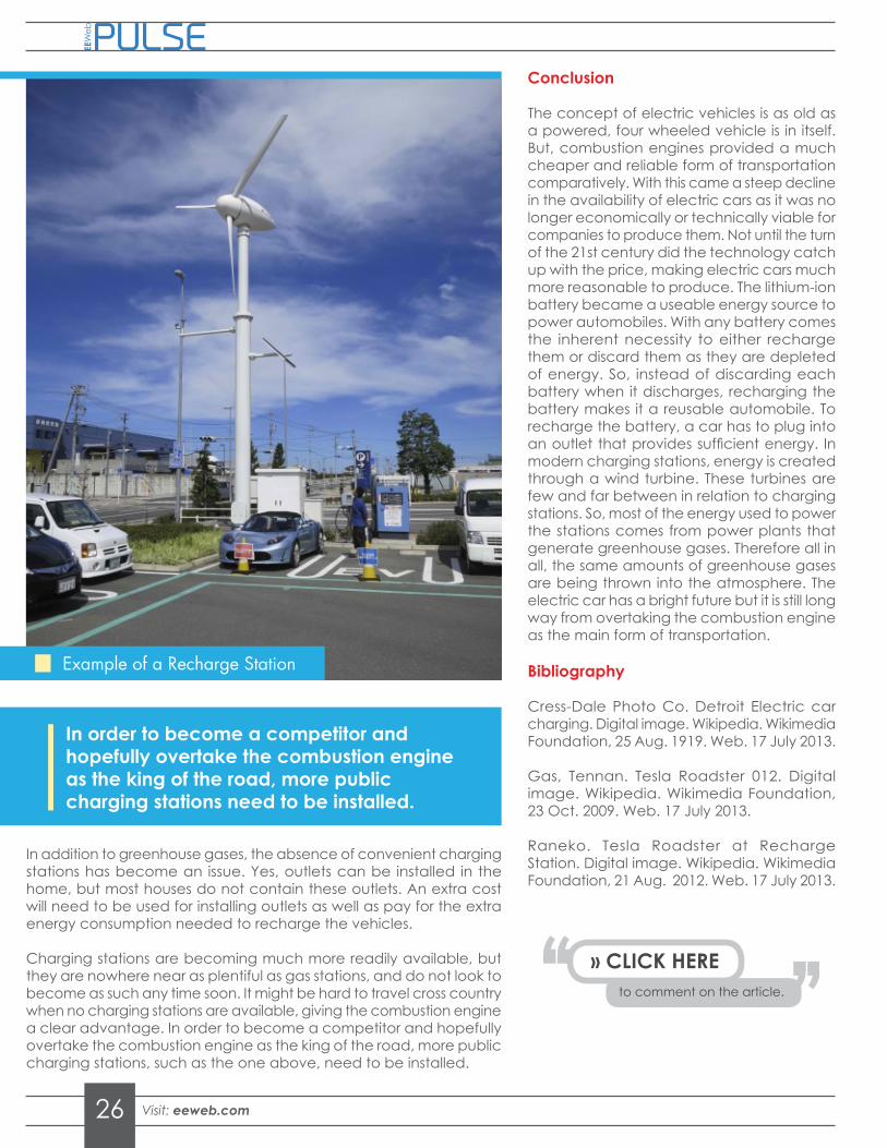
In addition to greenhouse gases, the absence of convenient charging stations has become an issue. Yes, outlets can be installed in the home, but most houses do not contain these outlets. An extra cost will need to be used for installing outlets as well as pay for the extra energy consumption needed to recharge the vehicles.
Charging stations are becoming much more readily available, but they are nowhere near as plentiful as gas stations, and do not look to become as such any time soon. It might be hard to travel cross country when no charging stations are available, giving the combustion engine a clear advantage. In order to become a competitor and hopefully overtake the combustion engine as the king of the road, more public charging stations, such as the one above, need to be installed.
Conclusion
The concept of electric vehicles is as old as a powered, four wheeled vehicle is in itself. But, combustion engines provided a much cheaper and reliable form of transportation comparatively. With this came a steep decline in the availability of electric cars as it was no longer economically or technically viable for companies to produce them. Not until the turn of the 21st century did the technology catch up with the price, making electric cars much more reasonable to produce. The lithium-ion battery became a useable energy source to power automobiles. With any battery comes the inherent necessity to either recharge them or discard them as they are depleted of energy. So, instead of discarding each battery when it discharges, recharging the battery makes it a reusable automobile. To recharge the battery, a car has to plug into an outlet that provides sufficient energy. In modern charging stations, energy is created through a wind turbine. These turbines are few and far between in relation to charging stations. So, most of the energy used to power the stations comes from power plants that generate greenhouse gases. Therefore all in all, the same amounts of greenhouse gases are being thrown into the atmosphere. The electric car has a bright future but it is still long way from overtaking the combustion engine as the main form of transportation.
Bibliography
Cress-Dale Photo Co. Detroit Electric car charging. Digital image. Wikipedia. Wikimedia Foundation, 25 Aug. 1919. Web. 17 July 2013.
Gas, Tennan. Tesla Roadster 012. Digital image. Wikipedia. Wikimedia Foundation, 23 Oct. 2009. Web. 17 July 2013.
Raneko. Tesla Roadster at Recharge Station. Digital image. Wikipedia. Wikimedia Foundation, 21 Aug. 2012. Web. 17 July 2013.
Example of a Recharge Station
In order to become a competitor and hopefully overtake the combustion engine as the king of the road, more public charging stations need to be installed.
to comment on the article.
» CLICK HERE

19MHz Rad Hard 40V Quad Rail-to-Rail Input-Output, Low-Power Operational AmplifiersISL70444SEHThe ISL70444SEH features four low-power amplifiers optimized to provide maximum dynamic range. These op amps feature a unique combination of rail to rail operation on the input and output as well as a slew enhanced front end that provides ultra fast slew rates positively proportional to a given step size; thereby increasing accuracy under transient conditions, whether it’s periodic or momentary. They also offer low power, low offset voltage, and low temperature drift, making it ideal for applications requiring both high DC accuracy and AC performance. With <5µs recovery for Single Event Transients (SET) (LETTH = 86.4MeV•cm2/mg), the number of filtering components needed is drastically reduced. The ISL70444SEH is also immune to Single Event Latch-up as it is fabricated in Intersil’s Proprietary PR40 Silicon On Insulator (SOI) process.
They are designed to operate over a single supply range of 2.7V to 40V or a split supply voltage range of ±1.35V to ±20V. Applications for these amplifiers include precision instrumentation, data acquisition, precision power supply controls, and process controls.
The ISL70444SEH is available in a 14 Ld Hermetic Ceramic Flatpack and die forms that operate over the temperature range of -55°C to +125°C.
Related Literature• ISL70444SEH Evaluation Board User’s Guide AN1824
• ISL70444SEH Single Event Effects Report AN1838
• ISL70444SEH SMD 5962-13214
• ISL70444SEH Radiation Test Report
Features• Electrically screened to DLA SMD# 5962-13214
• Acceptance tested to 50krad(Si) (LDR) wafer-by-wafer
• <5µs recovery from SEE (LETTH = 86.4MeV•cm2/mg)
• Unity gain stable
• Rail-to-rail input and output
• Wide gain·bandwidth product . . . . . . . . . . . . . . . . . . . . 19MHz
• Wide single and dual supply range. . . . . . . . 2.7V to 40V Max• Low input offset voltage . . . . . . . . . . . . . . . . . . . . . . . . . 300µV• Low current consumption (per amplifier) . . . . . . . 1.1mA, Typ• No phase reversal with input overdrive• Slew rate
- Large signal . . . . . . . . . . . . . . . . . . . . . . . . . . . . . . . . 60V/µs• Operating temperature range. . . . . . . . . . . . -55°C to +125°C
• Radiation tolerance- High dose rate (50-300rad(Si)/s). . . . . . . . . . . 300krad(Si)- Low dose rate (0.01rad(Si)/s) . . . . . . . . . . . . 100krad(Si)*- SEL/SEB LETTH . . . . . . . . . . . . . . . . . . . . 86.4MeV•cm2/mg
* Product capability established by initial characterization.
Applications• Precision instruments
• Active filter blocks
• Data acquisition
• Power supply control
• Process control
FIGURE 1. TYPICAL APPLICATION: SINGLE-SUPPLY, HIGH-SIDE CURRENT SENSE AMPLIFIER
FIGURE 2. VOS SHIFT vs HIGH DOSE RATE RADIATION
-IN
+IN
RF
RREF+
ISL70444
+2.7V
V-
V+
RIN-
10kΩ
RIN+
10kΩ
-
+
100kΩ
VREF
100kΩ
VOUT
LOAD
RSENSE
to 40V
VOUT = 10 (ILOAD * RSENSE)
+
-30
-20
-10
0
10
20
30
0 50 100 150 200 250 300 krad (Si)
V OS
(µV)
Vs = ±18V
GROUNDED
BIASED
June 14, 2013FN8411.1
Get the Datasheet and Order Samples
http://www.intersil.com
Intersil (and design) is a registered trademark of Intersil Americas Inc. Copyright Intersil Americas Inc. 2013All Rights Reserved. All other trademarks mentioned are the property of their respective owners.


