Efficient Jumpgliding: Theory and Design Considerations Alexis Lussier Desbiens, Morgan Pope, Forrest Berg, Zhi Ern Teoh, Julia Lee, Mark Cutkosky Abstract— A dynamic model of a jump glider is presented and correlated with the results obtained with a prototype glider. The glider uses a carbon fiber spring and a main wing that pivots approximately parallel to the airflow during ascent and latches into place for a gliding descent. The robot demonstrates longer traveled distance than an equivalent drag-free ballistic mass. A detailed numerical and a simplified algebraic model are also introduced, which are useful for exploring design tradeoffs and performance. These models suggest ways to improve the traveled distance and indicate that with modest variations in the wing angle of attack during ascent, one can choose from a variety of launch angles to accommodate variations in ground friction without greatly compromising range. I. I NTRODUCTION Jumping has long been recognized as an effective form of locomotion for animals and robots that need to clear large obstacles relative to body size. It is particularly effective at small length scales, where the inherent strength/weight ratio is high. Many successful jumping robots have been demonstrated and a number of papers have focused on the problem of maximizing energy storage and efficiently con- verting stored elastic energy to kinetic energy for impressive performance [1]–[10]. Several groups have also added added deployable surfaces [11], [12] or fixed wings [13], [14] for improved range and control. In nature, animals like the flying squirrel [15], the flying snake [16], and the flying fish [17] use aerodynamic surfaces on their bodies to dramatically extend the range and accuracy of their leaps, particularly when jumping from elevated perches. In comparison to a ballistic jumper, adding the ability to glide can offer several advantages including: • extended horizontal range for a given amount of stored energy • greater control over the details of the trajectory (e.g. to allow a higher launch angle on slippery surfaces) • a gentler landing. However, the ability to achieve these benefits depends criti- cally on how much extra weight and drag are associated with the controllable airfoil surfaces. The contribution of this paper is to examine in detail the interrelationships among stored energy, lift, drag and trajectory control for efficient jump gliding with a glider that utilizes a pivoting wing. Section II presents the jump glider design, including the pivotable wing and carbon fiber bow spring. Section III presents a planar dynamic model The authors are with the Biomimetics and Dextrous Manipulation Laboratory (BDML), Stanford University, Stanford, CA 94303, USA [email protected], [email protected], [email protected]1- Launch 2- Ascent 3- Glide spring (compressed) battery and servo pin joint spring (extended) foot elevator magnetic latch wing Fig. 1. Jump glider design with pivoting wing and carbon fiber spring, in the three principal states of a basic jump glide: launching, ascending, and gliding. of the glider. At the Reynolds numbers that apply for this prototype, a flat plate model of lift and drag is appropriate. The model elucidates the effects of friction at the wing pivot and the location of the center of mass of the wing. The results of experiments with the prototype are compared with predictions from the dynamic model and shown to match closely. However, for the purposes of exploring design tradeoffs, it is desirable to have a simpler, algebraic model for studying the effects of parametric variations. Such a model is introduced in Section IV and shown to match both the detailed model and empirical results reasonably well. Section V presents conclusions to be drawn from this work and future extensions to the models and jump glider design. II. PROTOTYPE As noted in [18] for the study of jumping insects, the ratio of drag to inertial forces (h v A/m) should be minimized for high efficiency during the ascending phase. In this equation, h v is the corresponding height of a jump in vacuum (related
Transcript
Efficient Jumpgliding: Theory and Design Considerations
Alexis Lussier Desbiens, Morgan Pope, Forrest Berg, Zhi Ern Teoh, Julia Lee, Mark Cutkosky
Abstract— A dynamic model of a jump glider is presentedand correlated with the results obtained with a prototype glider.The glider uses a carbon fiber spring and a main wing thatpivots approximately parallel to the airflow during ascent andlatches into place for a gliding descent. The robot demonstrateslonger traveled distance than an equivalent drag-free ballisticmass. A detailed numerical and a simplified algebraic model arealso introduced, which are useful for exploring design tradeoffsand performance. These models suggest ways to improve thetraveled distance and indicate that with modest variations inthe wing angle of attack during ascent, one can choose from avariety of launch angles to accommodate variations in groundfriction without greatly compromising range.
I. INTRODUCTION
Jumping has long been recognized as an effective form oflocomotion for animals and robots that need to clear largeobstacles relative to body size. It is particularly effectiveat small length scales, where the inherent strength/weightratio is high. Many successful jumping robots have beendemonstrated and a number of papers have focused on theproblem of maximizing energy storage and efficiently con-verting stored elastic energy to kinetic energy for impressiveperformance [1]–[10]. Several groups have also added addeddeployable surfaces [11], [12] or fixed wings [13], [14] forimproved range and control.
In nature, animals like the flying squirrel [15], the flyingsnake [16], and the flying fish [17] use aerodynamic surfaceson their bodies to dramatically extend the range and accuracyof their leaps, particularly when jumping from elevatedperches.
In comparison to a ballistic jumper, adding the ability toglide can offer several advantages including:• extended horizontal range for a given amount of storedenergy• greater control over the details of the trajectory (e.g. toallow a higher launch angle on slippery surfaces)• a gentler landing.
However, the ability to achieve these benefits depends criti-cally on how much extra weight and drag are associated withthe controllable airfoil surfaces.
The contribution of this paper is to examine in detailthe interrelationships among stored energy, lift, drag andtrajectory control for efficient jump gliding with a gliderthat utilizes a pivoting wing. Section II presents the jumpglider design, including the pivotable wing and carbon fiberbow spring. Section III presents a planar dynamic model
Fig. 1. Jump glider design with pivoting wing and carbon fiber spring, inthe three principal states of a basic jump glide: launching, ascending, andgliding.
of the glider. At the Reynolds numbers that apply for thisprototype, a flat plate model of lift and drag is appropriate.The model elucidates the effects of friction at the wingpivot and the location of the center of mass of the wing.The results of experiments with the prototype are comparedwith predictions from the dynamic model and shown tomatch closely. However, for the purposes of exploring designtradeoffs, it is desirable to have a simpler, algebraic model forstudying the effects of parametric variations. Such a modelis introduced in Section IV and shown to match both thedetailed model and empirical results reasonably well. SectionV presents conclusions to be drawn from this work and futureextensions to the models and jump glider design.
II. PROTOTYPE
As noted in [18] for the study of jumping insects, the ratioof drag to inertial forces (hvA/m) should be minimized forhigh efficiency during the ascending phase. In this equation,hv is the corresponding height of a jump in vacuum (related
cutkosky
Typewritten Text
cutkosky
Typewritten Text
cutkosky
Typewritten Text
cutkosky
Typewritten Text
cutkosky
Typewritten Text
to be presented at IEEE ICRA 2013
to takeoff velocity), A the exposed area of the body and mthe mass of the system. The jump-gliding plane presentedhere reduces the exposed wing area during ascent with apivoting wing that can passively align itself with the air flow.The wing freely rotates for low drag during ascent but latchesinto place with a magnet to provide lift on descent. The planeis controlled using a single servo that adjusts the angle ofthe elevator. The following subsections describe the plane,the pivoting wing and the carbon fiber spring.
A. Airplane and wing design
The airplane was designed to have a high glide ratio(i.e., high lift over drag, L/D) at the relatively low speedsachievable from jumping. For an airplane with a wingspanin the range of 0.5-1.0 m, flying at approximately 4 m/s,the Reynolds number is about 30,000. At these scales themaximum L/D of a rectangular wing with an aspect ratio(A) of 6 can be expected to be around 8-12 [19], [20]. Themaximum L/D ratio occurs at 3-4o of angle of attack (AoA)and at a lift coefficient of CL=0.4. The same studies showthat a rectangular planform (wing shape) withA=6 performsbetter than a similar elliptical planform. Furthermore, a wingwithA=6 provides similar performance to a wing of higheraspect ratio without the practical disadvantages of a verylong and slender wing. It was found that slightly betterperformance could be obtained with a 5% cambered plate.However, a flat wing was used in the present case for easeof manufacturing and damage repair.
To allow our 30g prototype to glide, the lift has to equalthe gravity force, or mg = 1/2ρAv2CL. Solving for thewing area, A, and keeping the desired AR=6, the wing wassized to be 70 cm long with a cord of 11.5 cm. A threadis connected between the wing tips and pulls the wing intoa slight upward bow (Fig 1), resulting in a slight dihedralangle for stability and reducing the tendency of the wingto bend excessively during the high acceleration associatedwith jumping.
The wing aerodynamical center (i.e. the quarter cord) islocated just behind the center of mass (CM) of the airplanewhile gliding, while the elevator aerodynamical center islocated 34 cm behind the CM. The elevator span is 14 cmand has a cord of 8 cm. This configuration allows the airplaneto be longitudinally stable during gliding. The launch springis connected to the airplane with a pivot at its center ofmass, creating minimal angular acceleration and allowing forstraight jumps at various angles.
The wing is built out of 1 mm thick Pro-formanceTM
foam with a leading edge carbon fiber spar. The roundspar freely pivots within a styrene bushing attached to thebody, allowing the wing to pivot. Lower friction could beachieved at this joint but is not needed, as will be shownin the following sections. Latching is accomplished at theend of the upward phase using two small magnets, one eachon the wing and the body. The body is built out of balsawood with 0.25 mm thick laser cut fiberglass FRP sheetfor reinforcement. The airplane also has onboard a 90mAhLiPo battery and a 1.0g Micro 9-S-4CH receiver that controls
a 2.5g Blue Arrow Servo connected to the elevator. Thelaunch spring is currently manually loaded by pulling on aSpectra line, which is then cut by a heated nichrome wire fortakeoff. This has proven to be sufficient to test jump-glidingcapabilities and can be modified for autonomous operationin the future.
B. Spring designThe main criteria considered when designing the jumping
mechanism are the the mass of the foot, the force profile onthe ground and the energy density of the spring mechanism.The mass of the foot should be minimized as it comes toa stop at the end of the decompression phase, dissipatingkinetic energy in the process [2]. Equally important is theprofile of the ground reaction force. Traditional linear springshave a triangular force profile that can cause premature lift-off and high initial accelerations that excite various structuralmodes. To overcome these limitations, one possibility is toemploy a geared power transmission system [1], [2]. Anotherpossibility is to use a bow spring providing a nearly constantforce profile. The advantages of a carbon fiber bow spring forjumping have been noted previously [6]. Although a higherspecific energy can be obtained with elastomers, a carbonfiber bow spring nonetheless provides a favorable energydensity per mass, σ2
f/ρE [21], without the deterioration overtime of rubber.
Symmetry axis
Fig. 2. Representation of half of the U-shaped carbon spring model usedto size the spring.
The spring, which is bent into a U shape, is an elasticaand can be approximated with a series of rigid elementsconnected by torsional springs of stiffness ki = EIi/∆L,where Ii is the second moment of area and ∆L is thediscretization length of each segment, as described in [22]and illustrated in Fig. 2. To find the angular displacements,qi, when the tips are held a distance Lcompression apart, itsuffices to minimize the potential energy:
minimizeqi
1
2
20∑i=2
ki−1qi
subject to rend/0 · x = 0
rend/0 · y = Lcompression
This optimization problem can be solved using Lagrangemultipliers. Once the angular displacements are found, thespring energy, tip forces, maximum bending moment andmaximum stress are calculated.
The model suggests that to provide at least 0.53J, enoughto propel a 30g airplane to a height of 1m with a forwardvelocity of 4m/s, one can use two unidirectional carbon fibercomposite beams 15cm long, 3.8mm wide and 0.7mm thick.The Young’s modulus of the composite was measured as54GPa. When the distance between the tips of the spring iscompressed to 5cm the stored energy is 0.63J. The maximumstress is 759MPa, only 38% of the 2GPa ultimate strengthof the unidirectional carbon fiber. With a density of 1550kg/m3, the spring mass is 1.2g.
0.05 0.06 0.07 0.08 0.09 0.1 0.11 0.12 0.13 0.140
2
4
6
8
10
12
Distance between tips (m)
For
ce (
N)
ModelExperiment
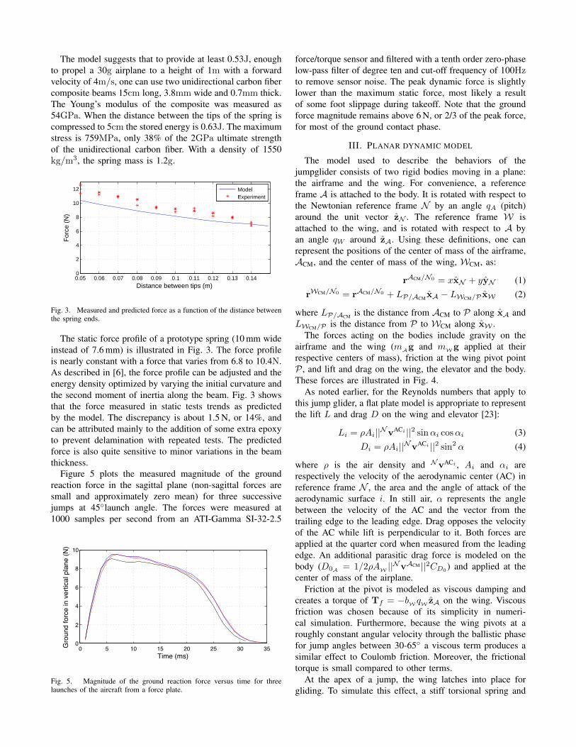
Fig. 3. Measured and predicted force as a function of the distance betweenthe spring ends.
The static force profile of a prototype spring (10 mm wideinstead of 7.6 mm) is illustrated in Fig. 3. The force profileis nearly constant with a force that varies from 6.8 to 10.4N.As described in [6], the force profile can be adjusted and theenergy density optimized by varying the initial curvature andthe second moment of inertia along the beam. Fig. 3 showsthat the force measured in static tests trends as predictedby the model. The discrepancy is about 1.5 N, or 14%, andcan be attributed mainly to the addition of some extra epoxyto prevent delamination with repeated tests. The predictedforce is also quite sensitive to minor variations in the beamthickness.
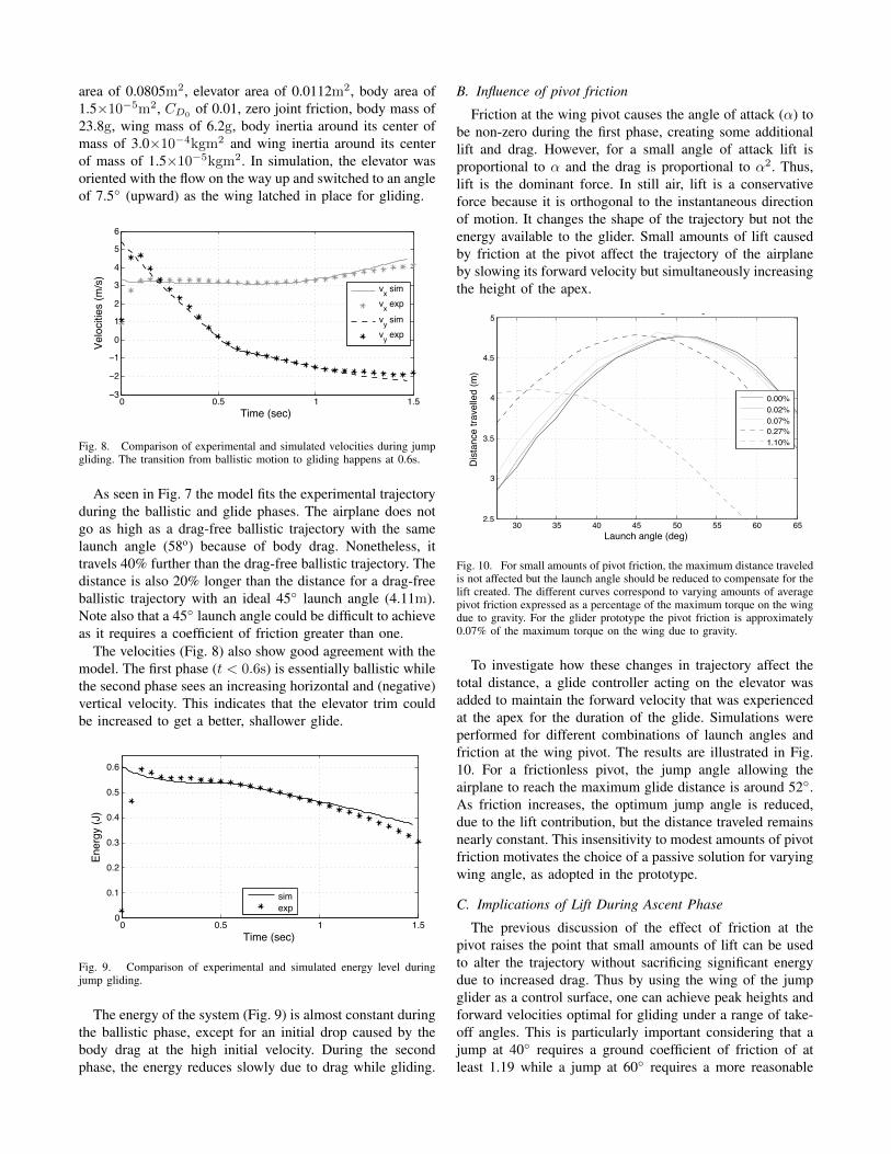
Figure 5 plots the measured magnitude of the groundreaction force in the sagittal plane (non-sagittal forces aresmall and approximately zero mean) for three successivejumps at 45◦launch angle. The forces were measured at1000 samples per second from an ATI-Gamma SI-32-2.5
0 5 10 15 20 25 30 350
2
4
6
8
10
Gro
und
forc
e in
ver
tical
pla
ne (N
)
Time (ms)
Fig. 5. Magnitude of the ground reaction force versus time for threelaunches of the aircraft from a force plate.
force/torque sensor and filtered with a tenth order zero-phaselow-pass filter of degree ten and cut-off frequency of 100Hzto remove sensor noise. The peak dynamic force is slightlylower than the maximum static force, most likely a resultof some foot slippage during takeoff. Note that the groundforce magnitude remains above 6 N, or 2/3 of the peak force,for most of the ground contact phase.
III. PLANAR DYNAMIC MODEL
The model used to describe the behaviors of thejumpglider consists of two rigid bodies moving in a plane:the airframe and the wing. For convenience, a referenceframe A is attached to the body. It is rotated with respect tothe Newtonian reference frame N by an angle qA (pitch)around the unit vector zN . The reference frame W isattached to the wing, and is rotated with respect to A byan angle qW around zA. Using these definitions, one canrepresent the positions of the center of mass of the airframe,ACM, and the center of mass of the wing, WCM, as:
where LP/ACM is the distance from ACM to P along xA andLWCM/P is the distance from P to WCM along xW .
The forces acting on the bodies include gravity on theairframe and the wing (mAg and mWg applied at theirrespective centers of mass), friction at the wing pivot pointP , and lift and drag on the wing, the elevator and the body.These forces are illustrated in Fig. 4.
As noted earlier, for the Reynolds numbers that apply tothis jump glider, a flat plate model is appropriate to representthe lift L and drag D on the wing and elevator [23]:
where ρ is the air density and NvACi , Ai and αi arerespectively the velocity of the aerodynamic center (AC) inreference frame N , the area and the angle of attack of theaerodynamic surface i. In still air, α represents the anglebetween the velocity of the AC and the vector from thetrailing edge to the leading edge. Drag opposes the velocityof the AC while lift is perpendicular to it. Both forces areapplied at the quarter cord when measured from the leadingedge. An additional parasitic drag force is modeled on thebody (D0A = 1/2ρAW ||NvACM ||2CD0
) and applied at thecenter of mass of the airplane.
Friction at the pivot is modeled as viscous damping andcreates a torque of Tf = −bW qW zA on the wing. Viscousfriction was chosen because of its simplicity in numeri-cal simulation. Furthermore, because the wing pivots at aroughly constant angular velocity through the ballistic phasefor jump angles between 30-65◦ a viscous term produces asimilar effect to Coulomb friction. Moreover, the frictionaltorque is small compared to other terms.
At the apex of a jump, the wing latches into place forgliding. To simulate this effect, a stiff torsional spring and
Fig. 4. Reference frames and forces on the plane body, wing, and elevator used in the detailed model. Left drawing highlights forces and moments onthe body, right drawing highlights forces and moments on the wing. Reaction forces at the wing pivot (P) not shown for simplicity.
damper are enabled when the absolute value of qW issmaller than 2◦. For simplicity, the spring-powered launch isapproximated by specifying the initial velocity of the airplaneat take-off.
The acceleration of the center of mass of each body iin frame N is obtained by differentiating its position twicewith respect to time in reference frame N and is denotedas NaiCM . The angular velocity and acceleration of a body iin reference frame N are respectively denoted as Nωi andNαi. Following a D’Alembert approach, the sums of theforces and moments on the system are equated to the sumsof the inertial and other dynamic terms, referred to as theeffective forces and effective moments [24].
The three resulting vector equations consist of the sum offorces on the system (FS ) equated to the sum of effectiveforces (Eq. 5), the sum of moments around the airplanecenter of mass (MS/ACM ) equated to the sum of the effectivemoments of the system around the same point (Eq. 6), andthe sum of moments on the wing around the pivot (MW/P )equated with the effective moment of the wing around thatpoint (Eq. 7).
FS = (mA +mW) ∗ (NaACM + NaACM) (5)
MS/ACM = IA/ACM ·NαA + IW/ACM ·NαW + ...
mW ∗ rWCM/ACM × NaACM (6)
MW/P = IW/P ·NαW +mW ∗ rWCM/P × NaP (7)
Four scalar equations are obtained by taking the dotproduct of each side of these vector equations with respectto appropriate unit vectors. Eq. 5 is dotted with xN andyN . Eq. 6 and 7 are dotted with zN . The resulting scalarequations are solved for x, y, qA and qW . In the present casethe solutions were obtained using Motion Genesis [25] andsolved numerically in Matlab.
A. Results
The airplane was launched at various angles and thetrajectory recorded at 200 fps with a high speed camera. Theelevator was manually controlled by first aligning it with thelaunch angle to minimize drag on the way up and then flippedto its trimmed position for gliding as the airplane reached its
apex. Figure 6 shows a typical flight for a launch angle of60◦.
Fig. 6. Typical jumpgliding trajectory for the jump glider. Each image isspaced by 150ms.
The camera was calibrated to compensate for distortionand the center of mass position was tracked in each frame.The resulting position was filtered by fitting a 12th orderpolynomial. The high degree was necessary to accommodatethe change from ballistic motion to gliding. The polynomialwas then differentiated to obtain the velocity. The energylevel was calculated by adding potential and kinetic energies.Results are illustrated in Figs. 7-9.
The model parameters used in these figures are: wing
0 0.5 1 1.5 2 2.5 3 3.5 4 4.5 50
0.5
1
1.5
2
x (m)
y (m
)
ballisticsimexp
A
B
CD
wing
elevator
Fig. 7. Comparison of the experimental trajectory, the simulated trajectoryand a ballistic trajectory with the same energy and launch angle (58o).Overlaid on that figure are cartoons of the jump glider states. The wing andelevator are initially aligned with the launch angle (A). During the upwardphase, the wing freely rotates to stay aligned with the airflow (B). At theapex (C), the wing reaches a horizontal orientation and latches to the bodywhile the elevator is moved up to its gliding position. The wing and elevatorremain in that configuration for the full glide phase (D).
area of 0.0805m2, elevator area of 0.0112m2, body area of1.5×10−5m2, CD0
of 0.01, zero joint friction, body mass of23.8g, wing mass of 6.2g, body inertia around its center ofmass of 3.0×10⁻⁴kgm2 and wing inertia around its centerof mass of 1.5×10⁻⁵kgm2. In simulation, the elevator wasoriented with the flow on the way up and switched to an angleof 7.5◦ (upward) as the wing latched in place for gliding.
0 0.5 1 1.5−3
−2
−1
0
1
2
3
4
5
6
Time (sec)
Velo
citie
s (m
/s)
vx simvx expvy simvy exp
Fig. 8. Comparison of experimental and simulated velocities during jumpgliding. The transition from ballistic motion to gliding happens at 0.6s.
As seen in Fig. 7 the model fits the experimental trajectoryduring the ballistic and glide phases. The airplane does notgo as high as a drag-free ballistic trajectory with the samelaunch angle (58o) because of body drag. Nonetheless, ittravels 40% further than the drag-free ballistic trajectory. Thedistance is also 20% longer than the distance for a drag-freeballistic trajectory with an ideal 45◦ launch angle (4.11m).Note also that a 45◦ launch angle could be difficult to achieveas it requires a coefficient of friction greater than one.
The velocities (Fig. 8) also show good agreement with themodel. The first phase (t < 0.6s) is essentially ballistic whilethe second phase sees an increasing horizontal and (negative)vertical velocity. This indicates that the elevator trim couldbe increased to get a better, shallower glide.
0 0.5 1 1.50
0.1
0.2
0.3
0.4
0.5
0.6
Time (sec)
Ener
gy (J
)
simexp
Fig. 9. Comparison of experimental and simulated energy level duringjump gliding.
The energy of the system (Fig. 9) is almost constant duringthe ballistic phase, except for an initial drop caused by thebody drag at the high initial velocity. During the secondphase, the energy reduces slowly due to drag while gliding.
B. Influence of pivot friction
Friction at the wing pivot causes the angle of attack (α) tobe non-zero during the first phase, creating some additionallift and drag. However, for a small angle of attack lift isproportional to α and the drag is proportional to α2. Thus,lift is the dominant force. In still air, lift is a conservativeforce because it is orthogonal to the instantaneous directionof motion. It changes the shape of the trajectory but not theenergy available to the glider. Small amounts of lift causedby friction at the pivot affect the trajectory of the airplaneby slowing its forward velocity but simultaneously increasingthe height of the apex.
30 35 40 45 50 55 60 652.5
3
3.5
4
4.5
5
Launch angle (deg)
Dis
tanc
e tra
velle
d (m
)
Influence of friction, v0 = 6 m/s, h0 = 0 m
0.00%0.02%0.07%0.27%1.10%
Fig. 10. For small amounts of pivot friction, the maximum distance traveledis not affected but the launch angle should be reduced to compensate for thelift created. The different curves correspond to varying amounts of averagepivot friction expressed as a percentage of the maximum torque on the wingdue to gravity. For the glider prototype the pivot friction is approximately0.07% of the maximum torque on the wing due to gravity.
To investigate how these changes in trajectory affect thetotal distance, a glide controller acting on the elevator wasadded to maintain the forward velocity that was experiencedat the apex for the duration of the glide. Simulations wereperformed for different combinations of launch angles andfriction at the wing pivot. The results are illustrated in Fig.10. For a frictionless pivot, the jump angle allowing theairplane to reach the maximum glide distance is around 52◦.As friction increases, the optimum jump angle is reduced,due to the lift contribution, but the distance traveled remainsnearly constant. This insensitivity to modest amounts of pivotfriction motivates the choice of a passive solution for varyingwing angle, as adopted in the prototype.
C. Implications of Lift During Ascent Phase
The previous discussion of the effect of friction at thepivot raises the point that small amounts of lift can be usedto alter the trajectory without sacrificing significant energydue to increased drag. Thus by using the wing of the jumpglider as a control surface, one can achieve peak heights andforward velocities optimal for gliding under a range of take-off angles. This is particularly important considering that ajump at 40◦ requires a ground coefficient of friction of atleast 1.19 while a jump at 60◦ requires a more reasonable
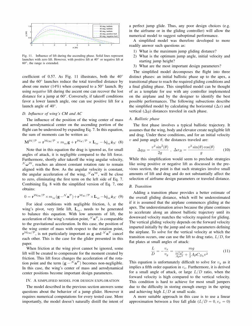
Fig. 11. Influence of lift during the ascending phase. Solid lines representlaunches with zero lift. However, with positive lift at 40◦ or negative lift at60◦, the range is extended.
coefficient of 0.57. As Fig. 11 illustrates, both the 40◦
and the 60◦ launches reduce the total travelled distance byabout one meter (14%) when compared to a 50◦ launch. Byusing negative lift during the ascent one can recover the lostdistance for a jump at 60◦. Conversely, if takeoff conditionsfavor a lower launch angle, one can use positive lift for alaunch angle of 40◦.
D. Influence of wing’s CM and AC
The influence of the position of the wing center of massand aerodynamical center on the ascending portion of theflight can be understood by expanding Eq. 7. In this equation,the sum of moments can be written as:
MW/P = rWCM/P ×mWg + rWAC/P × LW − bqW zN (8)
Note that in this equation the drag is ignored as, for smallangles of attack, it is negligible compared to the lift force.Furthermore, shortly after takeoff the wing angular velocity,NωW , reaches an almost constant rotation rate to remainaligned with the flow. As the angular velocity is constant,the angular acceleration of the wing, NαW , will be closeto zero, eliminating the first term on the left side of Eq. 7.Combining Eq. 8 with the simplified version of Eq. 7, oneobtains:
0 = rWCM/P×mW (g−NaP)+rWAC/P×LW−bqW zN (9)
For ideal conditions with negligible friction, b, at thewing’s pivot, very little lift, LW , needs to be generatedto balance this equation. With low amounts of lift, theacceleration of the wing’s rotation point, NaP , is comparableto the gravitational acceleration. In this case, the position ofthe wing center of mass with respect to the rotation point,rWCM/P , is not particularly important as g and NaP canceleach other. This is the case for the glider presented in thispaper.
When friction at the wing pivot cannot be ignored, somelift will be created to compensate for the moment created byfriction. This lift force changes the acceleration of the rota-tion point and the term (g−NaP) becomes non-negligible.In this case, the wing’s center of mass and aerodynamicalcenter positions become important design parameters.
IV. A SIMPLIFIED MODEL FOR DESIGN EXPLORATION
The model described in the previous section answers somequestions about the behavior of a jump glider. However itrequires numerical computations for every tested case. Moreimportantly, the model doesn’t naturally distill the intent of
a perfect jump glide. Thus, any poor design choices (e.g.in the airframe or in the gliding controller) will allow thenumerical model to suggest suboptimal performance.
A simplified model was therefore developed to morereadily answer such questions as:
1) What is the maximum jump gliding distance?2) What is the optimum jump angle, initial velocity and
starting jump height?3) What are the most important design parameters?The simplified model decomposes the flight into three
distinct phases: an initial ballistic phase up to the apex, atransitional phase to reach the required gliding conditions anda final gliding phase. This simplified model can be thoughtof as a template for use with any controller implementedon the airplane and by the designer to identify the bestpossible performances. The following subsections describethe simplified model by calculating the horizontal (∆x) andvertical (∆y) distances traveled in each phase.
A. Ballistic phase
The first phase involves a typical ballistic trajectory. Itassumes that the wing, body and elevator create negligible liftand drag. Under these conditions, and for an initial velocityv and jump angle θ, the distances traveled are:
∆yB =v2 sin2(θ)
2g, ∆xB =
v2 sin(θ) cos(θ)
g(10)
While this simplification would seem to preclude strategieslike using positive or negative lift as discussed in the pre-vious section, the point is that such strategies involve smallamounts of lift and drag and do not substantially affect theselection of airframe design parameters or traveled distance.
B. Transition
Adding a transition phase provides a better estimate ofthe overall gliding distance, which will be underestimatedif it is assumed that the airplane commences gliding at theapex. The underestimation arises because the plane continuesto accelerate along an almost ballistic trajectory until itsdownward velocity matches the velocity required for gliding.The vertical gliding velocity depends on the forward velocityimparted initially by the jump and on the parameters definingthe airplane. To solve for the vertical velocity at which thetransition occurs, one can use the lift to drag ratio, L/D, forflat plates at small angles of attack:
L
D= −vx
vy=
mgm2g2
Aρv2 + 12AρCD0
v2(11)
This equation is unfortunately difficult to solve for vy as itimplies a fifth order equation in vx. Furthermore, it is derivedfor a small angle of attack, or large L/D ratio, when theforward velocity is high compared to the vertical velocity.This condition is hard to achieve for most small jumpersdue to the difficulty in storing enough energy in the springand achieving high L/D at small scale.
A more suitable approach in this case is to use a linearapproximation between a free fall glide (L/D = 0, vx = 0)
and a glide at the maximum L/D. Differentiating Eq. 11with respect to the velocity v and equating to zero, one canfind the velocity at maximum lift to drag ratio and the valueof the maximum:
v2(L/D)max=mg
ρA
√2
CD0
, (L/D)max =
√1
2CD0
. (12)
Assuming that the forward velocity vx at maximum L/Dare approximately equal to v(L/D)max , and knowing that L/Dis equal to zero at zero forward velocity, one can approximatethe relationship between the lift to drag ratio and the forwardvelocity as linear for vx < v(L/D)max :
L
D≈ (L/D)max
v(L/D)max
vx = − 1
vyGvx (13)
where the constant parameter vyG is defined as:
vyG = −√mg
ρA(8CD0
)1/4
. (14)
Using the preceding equations, the end of the transitionphase can be determined by equating the vertical velocityduring the ballistic transition phase to the vertical velocityrequired to start gliding (i.e., vyG ). With the end of the tran-sition phase known, it is possible to solve for the distance:
∆xT = −vyGgv cos θ , ∆yT =
1
2gv2yG (15)
C. Gliding
Once the transition phase is over and the vertical velocityis suitable for gliding, the airplane maintains a constant glideslope determined by the L/D ratio. The distance during thisphase is:
∆xG =L
D(∆yB −∆yT + ∆h)
= −v cos θ
vyG
(v2 sin2(θ)
2g−v2yG2g
+ ∆h
)(16)
where ∆h is the height drop between the start and finishpoint.
D. Results
With each phase defined, it is possible to calculate thetotal distance travelled:
∆x = ∆xB + ∆xT + ∆xG
=v2 sin θ cos θ
g− vyG
2gv cos θ...
−v3 sin2 θ cos θ
2gvyG− v cos θ
vyG∆h (17)
Under normal conditions, all terms of this equation arepositive as vyG is negative. Furthermore, even when only asmall lift to drag ratio is obtained by the gliding platform,the second term will be small compared to the others.
We can now return to the three questions posed at thebeginning of this section. In answer to questions 1 and 2,for a fixed airplane design (i.e. fixed vyG ), it is possible
30 35 40 45 50 55 60 65 700
1
2
3
4
5
6
7
8
Launch angle (deg)
Dis
tanc
e tra
vele
d (m
)
BallisticJump−gliding simpleJump−gliding detailed
Fig. 12. h0 = 0 m and v0 = 6 m/s
to describe the evolution of the optimal jump angle as thejump parameters v, θ and ∆h are varied by looking at Eq.17. The first term of this equation favors a 45◦ jump angle(due to sin θ cos θ), the third term favors a jump angle around54◦ (sin2 θ cos θ) and the last term favors a horizontal jump(cos θ). Each of these terms has a different importance asv and ∆h are varied. The third term can be dominant athigher launch speeds while the last term becomes dominantfor larger drops between the start and finish vertical positions.This effect can be seen in Figs. 12 -13. The optimal jumpangle on a flat surface is 50-52◦ but reduces to 45◦ whenthe drop height increases to 1 m.
30 35 40 45 50 55 60 65 700
2
4
6
8
10
12
Launch angle (deg)
Dis
tanc
e tra
vele
d (m
)
BallisticJump−gliding simpleJump−gliding detailed
Fig. 13. h0 = 1 m and v0 = 6 m/s
In partial answer to question 3, we see that the distanceis also affected by the airplane design. To increase it, theparameter vyG (Eq. 14) should be brought toward zero, whichmeans that the mass to lifting surface area ratio should bedecreased, along with the parasitic drag coefficient.
Figures 12 and 13 also reveal that the simplified modelover-predicts the traveled distance when compared to thedetailed model. This is because the full wing area is usedin Eq. 14 and, due to the design of the plane, the elevatorhas to create some negative lift to maintain the requiredmoment balance during gliding. This reduces the effectivesurface area responsible for creating lift. The area used bythe simpler model could be reduced to reflect this effect.Even better, the airplane could be redesigned so that theelevator creates negligible or positive lift while gliding.
Another difference is that the distance traveled in Fig. 7is smaller than predicted by both the detailed model and thesimplified model in Fig. 12. The reason is that the resultsfrom the detailed model in Fig. 12 were computed for zerobody area for purposes of comparison with the simplifiedmodel. The effect of body area can be seen in Fig. 7 whencomparing the height reached by the ballistic trajectory andthe height reached by the experimental trajectory. It is alsoseen as the initial energy drops in Fig. 9. This change oftrajectory cannot be attributed to the pivot friction, whichwould keep the energy nearly constant, as discussed inSection III-B. The models suggest that reducing the bodydrag would allow the airplane to travel between 0.5-1.2mfarther. The current jump glider already travels further thanan equivalent drag free point mass launched at 45◦. Anappropriate next benchmark would be traveling a longerhorizontal distance than a lighter, wingless jumping robotwith the same initial energy, which could be accomplishedthrough reduced body drag (and/or reduced wing mass, bettercontrol of the glide, improved L/D with wing curvatureand reduced wing mid section gap, or positive lift on theelevator). The current jump glider travels 5.01m while a23.8g ballistic jumper with 0.60J of energy would travel5.18m when launched at 45◦, assuming that there is enoughfriction at the foot to do so.
V. CONCLUSIONS AND FUTURE WORK
This paper verifies the intuitive conclusion that glidingcan increase the horizontal range of a jumping robot. Thepresented models provide additional insight into the benefitsof controllable aerodynamic surfaces. For example, duringthe upward ballistic phase, lift can be used to control theapex height and forward velocity from a range of launchangles without sacrificing significant energy in drag. As aconsequence, it is possible to choose a steeper launch angleon a slippery surface without significantly reducing range.In addition, in all phases of the maneuver, the aircraft canbenefit from the increased controllability offered by its wingswithout suffering significantly from increased drag.
More generally, the models provide insight regardingthe effects of various design parameters on jump glidingperformance – for example, to explore the merits of a morecomplex wing folding mechanism that reduces drag at theexpense of greater weight, or to evaluate the improvementpossible with a reduced body area.
Looking forward, improvements can be made to thelaunching spring and platform design, but the main extensionwill be to provide greater control during flight (e.g. to steeraround obstacles or to optimize the glide path), particularlywhen jumping from a height.
REFERENCES
[1] M. Kovac, M. Fuchs, A. Guignard, J. Zufferey, and D. Floreano, “Aminiature 7g jumping robot,” in IEEE International Conference onRobotics and Automation, 2008, pp. 373–378.
[2] J. Burdick and P. Fiorini, “Minimalist jumping robots for celestialexploration,” The International Journal of Robotics Research, vol. 22,no. 7-8, p. 653, 2003.
[3] P. Weiss, “Hop. . . hop. . . hopbots!: Designers of small, mobile robotstake cues from grasshoppers and frogs,” Science News, vol. 159, no. 6,pp. 88–91, 2001.
[4] E. Ackerman, “Boston dynamics sand flea robot demonstrates aston-ishing jumping skills,” IEEE Spectrum, March 2012.
[5] U. Scarfogliero, C. Stefanini, and P. Dario, “The use of compliantjoints and elastic energy storage in bio-inspired legged robots,” Mech-anism and Machine Theory, vol. 44, no. 3, pp. 580–590, 2009.
[6] G. Zeglin, “The bow leg hopping robot,” Ph.D. dissertation, CarnegieMellon University, 1999.
[7] B. Lambrecht, A. Horchler, and R. Quinn, “A Small, Insect-InspiredRobot that Runs and Jumps,” in IEEE International Conference onRobotics and Automation, 2005, pp. 1240–1245.
[8] H. Tsukagoshi, M. Sasaki, A. Kitagawa, and T. Tanaka, “Jumpingrobot for rescue operation with excellent traverse ability,” in 12thInternational Conference on Advanced Robotics, 2005, pp. 841–848.
[9] M. Wang, X.-z. Zang, J.-z. Fan, and J. Zhao, “Biological JumpingMechanism Analysis and Modeling for Frog Robot,” Journal of BionicEngineering, vol. 5, no. 3, pp. 181–188, Sep. 2008.
[10] A. Yamada, M. Watari, H. Mochiyama, and H. Fujimoto, “An asym-metric robotic catapult based on the closed elastica for jumping robot,”in IEEE International Conference on Robotics and Automation, May2008, pp. 232–237.
[11] M. A. Woodward and M. Sitti, “Design of a miniature integratedmulti-modal jumping and gliding robot,” International Conference onIntelligent Robots and Systems, 2011.
[12] R. Armour, K. Paskins, A. Bowyer, J. Vincent, and W. Megill,“Jumping robots: a biomimetic solution to locomotion across roughterrain,” Bioinspiration & Biomimetics, vol. 2, p. S65, 2007.
[13] M. Kovac, “Bioinspired jumping locomotion for miniature robotics,”Ph.D. dissertation, Ecole Polytechnique Federale de Lausanne, 2010.
[14] M. Kovac, W. Hraiz, O. Fauria, J. Zufferey, and D. Floreano, “Theepfl jumpglider: A hybrid jumping and gliding robot with rigid orfolding wings,” in IEEE International Conference on Robotics andBiomimetics (ROBIO), 2011, pp. 1503–1508.
[15] K. Vernes, “Gliding Performance of the Northern Flying Squirrel (Glaucomys Sabrinus ) in Mature Mixed Forest of Eastern Canada,”Journal of Mammalogy, vol. 82, no. 4, pp. 1026–1033, Nov. 2001.
[16] J. Davenport, “How and why do flying fish fly?” Reviews in FishBiology and Fisheries, vol. 4, no. 2, pp. 184–214, Jun. 1994.
[17] J. J. Socha, “Becoming airborne without legs: the kinematics oftake-off in a flying snake, Chrysopelea paradisi.” The Journal ofexperimental biology, vol. 209, Sep. 2006.
[18] H. Bennet-Clark and G. Alder, “The effect of air resistance on thejumping performance of insects,” Journal of Experimental Biology,vol. 82, no. 1, p. 105, 1979.
[19] A. Pelletier and T. Mueller, “Low reynolds number aerodynamics oflow-aspect-ratio, thin/flat/cambered-plate wings,” Journal of Aircraft,vol. 37, no. 5, pp. 825–832, 2000.
[20] E. Laitone, “Wind tunnel tests of wings and rings at low reynoldsnumbers.” Progress in Astronautics and Aeronautics, vol. 195, pp. 83–90, 2001.
[21] M. Ashby and M. Ashby, Materials selection in mechanical design.Cambridge Univ Press, 2005, vol. 519.
[22] L. Howell, Compliant mechanisms. Wiley-Interscience, 2001.[23] R. Cory and R. Tedrake, “Experiments in fixed-wing uav perching,”
in Proceedings of the AIAA Guidance, Navigation, and Control Con-ference, 2008.
[24] T. Kane and D. Levinson, Dynamics, theory and applications. Mc-Graw Hill, 1985.


![1 Efficient Transmit Beamspace Design for Search-free Based ... filearXiv:1305.4979v1 [cs.IT] 21 May 2013 1 Efficient Transmit Beamspace Design for Search-free Based DOA Estimation](https://static.documents.pub/doc/80x56/5d501e4688c99349728bd664/1-efcient-transmit-beamspace-design-for-search-free-based-13054979v1-csit.jpg)


