EFFECT OF FOUNDATION NONLINEARITY ON MODAL PROPERTIES OF
OFFSHORE TOWERS
By Mohamed H. El Naggar l and Milos Novak,2 Fellow, ASCE
ABSTRACT: An analysis of pile axial and lateral response to transient dynamic loading is presented allowingfor nonlinear soil behavior, the discontinuity conditions at the pile-soil interface, and energy dissipation throughradiation damping and soil hysteresis. In addition, the effect of neighboring piles is taken into account forpiles in a group. This analysis is used to derive the stiffness of foundation pil~s of fixed ~ff~hore towers. Th.eeffect of foundation nonlinearity and pile-soil-pile interaction on the dynamic charactenstlcs of the tower IS
investigated. It was found that the tower's dynamic characteristics are greatly influenced by the foundationnonlinearity and the pile-soil-pile interaction.
INTRODUCTION
Modal properties of offshore towers such as natural frequencies, mode shapes, and modal damping ratios affect thetower's response to waves, wind, and other dynamic loads.The closeness of the peak of the wave energy spectrum tothe natural frequency of the tower results in large amplifications of the tower response.
For pile-supported towers, the modal properties of the towerare greatly dependent on pile flexibility. In storm conditions,a drop in the fundamental natural frequencies of offshorestructures was observed. This drop is mainly attributed tosoftening in the foundation system and the nonlinear soilreactions due to excessive deflections or loads. The effect ofthis nonlinearity has not been fully appreciated and is usuallyneglected, along with the pile-soil-pile interaction, in the design of offshore towers in spite of their influence on modalcharacteristics of the tower and its response to environmentalloads.
The effect of nonlinearity on the foundation stiffness isaccounted for in this study. Further, the pile-soil-pile interaction is considered in the analysis. An equivalent linear pilegroup stiffness is derived, accounting for both nonlinearityand group effects. The group stiffness is incorporated in acomputer-based analysis of pile-supported offshore towersand the results of a parametric study of modal properties aregiven. The influence of foundation parameters on tower modalproperties is demonstrated.
NONLINEAR PILE-SOIL INTERACTION MODEL
The nonlinear soil model developed accounts for the nonlinear soil behavior and the gapping and slippage betweenthe pile and soil. The Winkler (1867) soil model is adoptedand soil displacements are assumed to be in either a verticalor a horizontal direction, depending on the direction of thepile shaft model. Formulations of the model are within thetime domain to account for the nonlinearity.
Axial Vibration
Fig. I shows the elements of the model implemented inthe analysis. The model allows for nonlinear soil behavior,
'Ass\. Prof.. Fac. of Engrg. Sci., Univ. of Western Ontario, London,Canada.
'Deceased Apr. 28.1994; formerly, Prof.. Fac. of Engrg. Sci., Univ.of Western Ontario, London, Ontario, Canada.
6601 JOURNAL OF GEOTECHNICAL ENGINEERING 1SEPTEMBER 1995
energy dissipation through radiation damping and soil hysteresis, and for interaction between piles. A brief explanationof these elements is given here for completeness, and fulldetails on the model may be found in El Naggar and Novak(1994a).
When a pile is subjected to high-level loading, the soilaround the pile may exhibit strong nonlinearity in the regionclose to the pile, and there might be relative movement between the soil and pile at the soil-pile interface. The soiloutside this region behaves more or less elastically. Therefore, the soil around the pile is divided into two regions: anonlinear inner region adjacent to the pile, and a linear regionfor the far field.
The outer field is modeled by a spring and a dashpot whoseconstants are derived from the plane strain solution given byNovak et al. (1978), assumed here as being frequency-independent. The nonlinear stress-strain relationship given byKondner (1963) is used to model the stress-strain behaviorin the inner nonlinear region. The pile node and the adjacentsoil node are connected by a rigid slider. When the shearforces in the slider reaches the maximum friction force allowed at the soil-pile interface, the rigid slider is disconnectedand the pile and soil nodes move independently. Reconnec-
Dolan
FIG. 1. Elements of Model for Nonlinear Analysis of Axial Response of Piles
J. Geotech. Engrg. 1995.121:660-668.
Dow
nloa
ded
from
asc
elib
rary
.org
by
Uni
vers
ity o
f N
ew H
amps
hire
on
09/3
0/13
. Cop
yrig
ht A
SCE
. For
per
sona
l use
onl
y; a
ll ri
ghts
res
erve
d.
Outer Field Element
(4)
deflection
!~Ii:i
"f!i
Inner-Field Element
The soil reaction of the inner field is modeled by a nonlinearspring the stiffness of which is calculated with the assumptionthat plane strain conditions hold, the inner field is a homogeneous isotropic viscoelastic medium, the pile is rigid andcircular, there is no separation at the soil-pile interface, andthe displacements are small. The stiffness solution under theseconditions was obtained by Novak and Sheta (1980) as
where ro and r l = inner and outer radii of the inner field,respectively; and Gm = modified shear modulus calculatedaccording to the strain level as
Gmax = initial shear modulus of the soil layer; 'T] mobilization ratio defined as 'T] = PIPu, where P is the horizontalload at the spring and Puis the ultimate resistance of thespring calculated using the standard relations given by theAmerican Petroleum Institute (API) recommendations (1991).
Interface Conditions
Discontinuity conditions of the motion between pile andsoil are caused by the slippage and gapping at the soil-pileinterface. To model these conditions logically the soil reactions to the pile motion at both sides are modeled separatelyas shown in Fig. 2. The load-deflection curve for a pile nodeat the topmost part of the pile, where soil-pile separationtakes place, is shown in Fig. 3 along with the correspondinghorizontal displacements of the soil nodes on both sides ofthe pile. For the pile initially loaded rightward, the soil nodeat the left is separated from the pile as the force in the nearfield element reaches zero, assuming the soil does not resisttension. The soil node on the right is pushed with the pile tothe right and Kill decreases as the load increases. During theunloading phase the pile also separates from the soil on itsright. When the pile is loaded more leftward, it comes intocontact with the soil node on its left and pushes it until unloading occurs again, separation takes place, and the pilereturns to its original position. The result is that soil nodesare left in a displaced position and a permanent gap develops.
Group Effect
For the lateral vibration, interaction between piles dependson the angle 6, between the lines of the two piles and the
Soil on LeftPile Face
Pileload
Soil on RightPile Face
(2a,b)
Inner Field Pile m
!-----H------!No Tension Connection
Pilei
Novak et at. (1978) solved the problem of the horizontalvibration of piles assuming plane strain conditions. This solution for the horizontal stiffness is complex. It is frequencydependent and is not suitable for the time domain analysis.However, the real and imaginary parts may be separated andthe solution can be written as
in which S,,1 and S'I2 are real; v = Poisson's ratio; and D =material damping ratio for the soil. The plot for (1) showsthat for the dimensionless frequency ao, ranging between 0.05and 0.5, typical of offshore loading and many other applications, S,,1 may be considered constant while Su2 increasesmonotonically with ao. These observations suggest that theouter-field element can be modeled by a spring and a dashpotwhose constants depend on Poisson's ratio, but they are frequency-independent and defined as
Lateral Vibration
2GroK, = GS",(v); c = --v:- S"z(ao = 0.5, v)
These frequency-independent parameters are used in the dynamic analysis in the time domain.
In each layer the soil model is divided into two parts, similarto the model for axial vibration. The only difference is thatthe soil reactions at both sides of the pile are modeled separately to account for the state of stress and discontinuityconditions at both sides as the load direction changes. Theelements of this model are shown in Fig. 2, and full detailson the model may be found in EI Naggar (1994).
tion of the pile-soil nodes occurs again when the relativevelocity between the pile and soil nodes is equal to zero.
Under the assumption of wave propagation in the horizontal direction only and a Winkler soil model, and assuminga linear variation of the interaction effect through each timestep, !::J.t, the interaction force between piles is accounted forin the group analysis.
DETAll.
FIG. 2. Elements of Model for Nonlinear Analysis of Lateral Response of Plies
FIG. 3. Pile and Soli Displacements for Case with Pile-Soli Separation
JOURNAL OF GEOTECHNICAL ENGINEERING / SEPTEMBER 1995/661
J. Geotech. Engrg. 1995.121:660-668.
Dow
nloa
ded
from
asc
elib
rary
.org
by
Uni
vers
ity o
f N
ew H
amps
hire
on
09/3
0/13
. Cop
yrig
ht A
SCE
. For
per
sona
l use
onl
y; a
ll ri
ghts
res
erve
d.
For any value of 6, (7) can be used to obtain the interactionforce, P. This force is to be considered in the group analysis.
A dot means differentiation with respect to time, u, and U l= displacements of nodes 1 and 2; PI = force in a rigid sliderconnecting the pile node and node I; Pz = soil resistance atnode 2; m l and m 2 = inner-field lumped masses; and Cm =
material damping in the inner field if required. The equationof motion for the outer field may be written as
EQUATIONS OF MOTION
The equations of motion for the inner field are
VLam,u, + cm(u, 1l2 ) + K",(U , ul ) P, (lla)
m2u2 - Cm(U, Ill) K",(u , U2) P2 (lib)
V.3.4
La= -- Vs7t(l-v)
(12)
FIG. 4. Assumed Apparent Velocities Emanating from LaterallyOscillating Pile
(13)
(14a,b)
-K,,) - Acc", 1K", + A",m l + Acc + K,
where P = force transmitted through the soil from pile topile.
Introducing compatibility and equilibrium between innerfield and outer field, we get
where E" = pile Young's modulus; R and A = its radius andcross-sectional area, respectively; and V, = initial shear-wavevelocity of the soil.
El Naggar and Novak (1994b) found that F 1 decreases as
The proposed analytical model may be applied to analyzethe response of the entire pile group, accounting directly forthe nonlinearity and the interaction between all piles at thesame time. An alternative approach is to solve just two pilesat a time, with the results to be superimposed to assemblethe global flexibility matrix of the entire group. The secondapproach may be very advantageous if it is implemented inconjunction with pile-soil-pile interaction factors and withsingle-pile solutions. To approximately account for groupnonlinearity in the analysis, the equivalent linear single-pileparameters and interaction factors have to be established depending on the P/Pu ratio.
Single Piles
The stiffness, for axial vibration, is approximated by theslope of the backbone of the hysteretic loop and the dampingis approximated by its area. Using the dimensionless parameters FI and Fz, the equivalent linear stiffness and dampingof a single pile may be computed as
where Am and A c = numerical integration constants for inertia and damping forces, respectively; and 01 and 02 = sumsof inertia forces and soil reactions at nodes 1 and 2, respectively, established in the previous time step. In the lateralvibration, w is replaced by u.
The equations of motion are derived and solved using thelinear acceleration assumption and the Newmark 13 methodfor direct time integration of the equations of motion, alongwith the modified Newton-Raphson iteration scheme used toderive and solve the governing equilibrium equations (Bathe1982).
PILE FOUNDATION STIFFNESS MATRIX
(6)
(8a)
(8b)
u(a", r, 6) = u"IjJ"(a,,, r, 6)
I f;" .u(a rOO) = - e --wo'IT(I- v)(r-ro)l.1,· 4rop (a )", , K , + ica" r " "
Assuming that waves propagate in the horizontal directiononly and also assuming a Winkler soil model, the displacement at any point in the elastic soil domain may be given(Makris and Gazetas 1992), in general, as
P = - [H2(r = r"W IU", I *' m = - K"um (10)
For 6 = 0° or 90° relevant values from (8) are to be used.
662/ JOURNAL OF GEOTECHNICAL ENGINEERING / SEPTEMBER 1995
where i = number of the time step; rml = distance betweenthe piles m and 1; tml - 1 = travel time between the two pilesminus one time step; HI and Hz = convolution integrals overthe period tJ.t; and the interaction force is
direction of the horizontal applied force, as well as the spacingbetween them. Gazetas and Dobry (1984) found that the 90°passive pile m (Fig. 4) is affected essentially only by S-waves,which emanate from active pile 1 and have a phase velocityof V,. They also found that the 0°-passive pile is affected bycompression-extension waves coming from the active pile andpropagating with an apparent phase velocity, which is equalto the so-called Lysmer's analog velocity V La (Gazetas andDobry 1984), given by
3.4V, ( )V/.o = n(1 _ v) 5
The interaction effect is assumed to vary linearly througheach time step tJ.t. The soil displacement at the axis of themth pile due to a disturbance at the lth pile is given by
In (6) Un = amplitude of the disturbance at the source; and1jJ" = an attenuation function accounting for the wave propagation away from the source and the radiation damping. Itis sufficient to compute 1jJ" only for 6 = 0° and 6 = 90°, andthe approximation by Poulos (1971) may be used to evaluate1jJ" at any angle 6 as
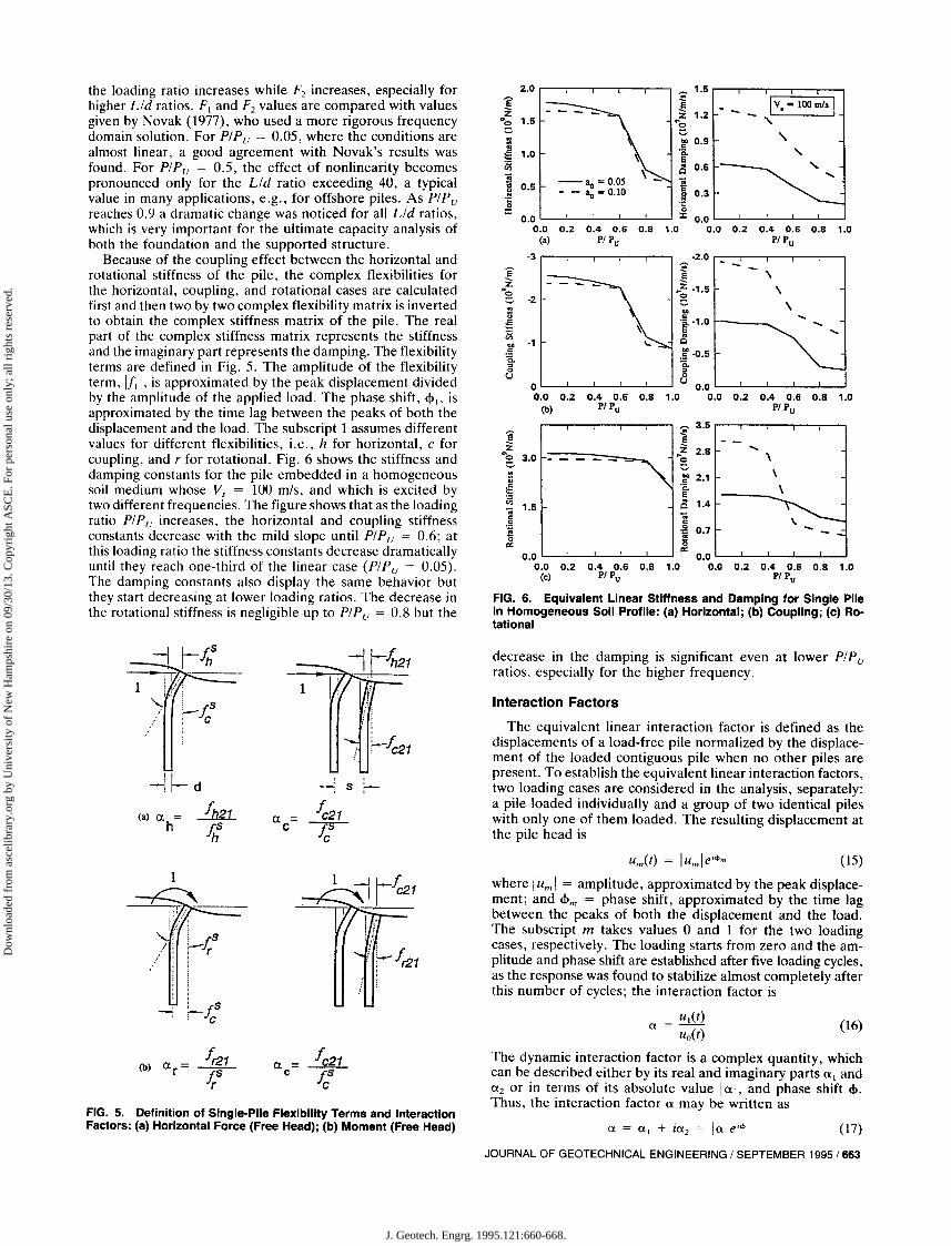
FIG. 6. Equivalent Linear Stiffness and Damping for Single PileIn Homogeneous 5011 Profile: (a) Horizontal; (b) Coupling; (c) Ro-tational
decrease in the damping is significant even at lower PIPuratios, especially for the higher frequency.
Interaction Factors
The equivalent linear interaction factor is defined as thedisplacements of a load-free pile normalized by the displacement of the loaded contiguous pile when no other piles arepresent. To establish the equivalent linear interaction factors,two loading cases are considered in the analysis, separately:a pile loaded individually and a group of two identical pileswith only one of them loaded. The resulting displacement atthe pile head is
si--
--.:f.! r- c21
J;;21-p-
C
a =C
Lrsi Jc
-H-d(a) a = f h21
h f..Sh
the loading ratio increases while F2 increases, especially forhigher Lid ratios. FI and F2 values are compared with valuesgiven by Novak (1977), who used a more rigorous frequencydomain solution. For PIPu = 0.05, where the conditions arealmost linear, a good agreement with Novak's results wasfound. For PIPu = 0.5, the effect of nonlinearity becomespronounced only for the Lid ratio exceeding 40, a typicalvalue in many applications, e.g., for offshore piles. As PIPureaches 0.9 a dramatic change was noticed for all Lid ratios,which is very important for the ultimate capacity analysis ofboth the foundation and the supported structure.
Because of the coupling effect between the horizontal androtational stiffness of the pile, the complex flexibilities forthe horizontal, coupling, and rotational cases are calculatedfirst and then two by two complex flexibility matrix is invertedto obtain the complex stiffness matrix of the pile. The realpart of the complex stiffness matrix represents the stiffnessand the imaginary part represents the damping. The flexibilityterms are defined in Fig. 5. The amplitude of the flexibilityterm, Ifll, is approximated by the peak displacement dividedby the amplitude of the applied load. The phase shift, <P1> isapproximated by the time lag between the peaks of both thedisplacement and the load. The subscript 1 assumes differentvalues for different flexibilities, i.e., h for horizontal, c forcoupling, and r for rotational. Fig. 6 shows the stiffness anddamping constants for the pile embedded in a homogeneoussoil medium whose Vs = 100 mis, and which is excited bytwo different frequencies. The figure shows that as the loadingratio PIPu increases, the horizontal and coupling stiffnessconstants decrease with the mild slope until PIPu = 0.6; atthis loading ratio the stiffness constants decrease dramaticallyuntil they reach one-third of the linear case (PIPu = 0.05).The damping constants also display the same behavior butthey start decreasing at lower loading ratios. The decrease inthe rotational stiffness is negligible up to PIPu = 0.8 but the
FIG. 5. Definition of Single-Pile Flexibility Terms and InteractionFactors: (a) Horizontal Force (Free Head); (b) Moment (Free Head) (17)
u",(t) = Iu'" Iei<l>m (15)
where Iu'" I = amplitude, approximated by the peak displacement; and <Pm = phase shift, approximated by the time lagbetween the peaks of both the displacement and the load.The subscript m takes values 0 and 1 for the two loadingcases, respectively. The loading starts from zero and the amplitude and phase shift are established after five loading cycles,as the response was found to stabilize almost completely afterthis number of cycles; the interaction factor is
ut(t)a = - (16)
u()(t)
The dynamic interaction factor is a complex quantity, whichcan be described either by its real and imaginary parts al anda2 or in terms of its absolute value Ia I, and phase shift <p.Thus, the interaction factor a may be written as
a =C
: f.Sr-r~
;;
1
JOURNAL OF GEOTECHNICAL ENGINEERING / SEPTEMBER 1995 /663
J. Geotech. Engrg. 1995.121:660-668.
Dow
nloa
ded
from
asc
elib
rary
.org
by
Uni
vers
ity o
f N
ew H
amps
hire
on
09/3
0/13
. Cop
yrig
ht A
SCE
. For
per
sona
l use
onl
y; a
ll ri
ghts
res
erve
d.
(19)
EN
~
x
Legs
v (-44)
y (-22)
y (+18)
l~"[fl"
If],,, J[Ff ) = [~)i1 [/L [/L. (20)
[/L [fl,,; [f)""
(l/!" a.f.aJ"
[fl 0.."[11 o.cfc (21)o..('lc urfr
a,J"o..cfc arfr
FIG. 8. Fixed Offshore Tower Used in Analysis
Eo...,
Eo...,
ENN
ENN
z
T
In (21), II - s = equivalent linear flexibility terms; and aj- s = complex equivalent linear interaction factors. Thesubscripts h, c, r, and 11 stand for the horizontal, coupling,
Pile Group Flexibility Matrix
The complex foundation stiffness matrix [K,l* is obtainedas the inverse of the complex foundation flexibility matrix[Ff ], i.e.
when large strains are encountered, while the phase shiftsmay be taken as being equal to the shifts available for linearconditions.
For a group of n piles, the foundation flexibility matrix is asymmetric 6n x 6n matrix, i.e.
where each of the diagonal submatrices [!];; = inverse of thesingle pile 6 x 6 complex stiffness matrix. The off-diagonalsubmatrices [flij represent the interaction between the degrees of freedom at the heads of piles i and j, i.e.
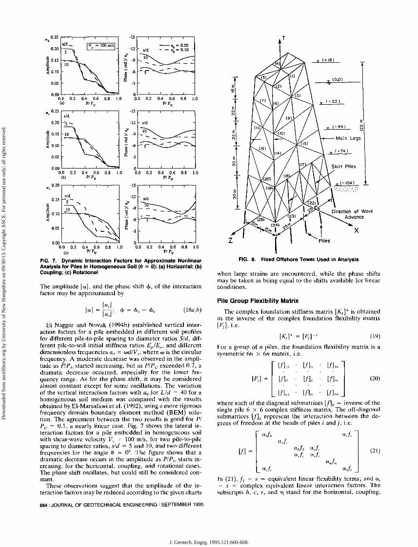
FIG. 7. Dynamic Interaction Factors for Approximate NonlinearAnalysis for Plies in Homogeneous Soil (9 = 0): (a) Horizontal; (b)Coupling; (c) Rotational
El Naggar and Novak (1994b) established vertical interaction factors for a pile embedded in different soil profilesfor different pile-to-pile spacing to diameter ratios Sid, different pile-to-soil initial stiffness ratios EplEso and differentdimensionless frequencies all = wdlVso where w is the circularfrequency. A moderate decrease was observed in the amplitude as PIPu started increasing, but as PIPu exceeded 0.7, adramatic decrease occurred, especially for the lower frequency range. As for the phase shift, it may be consideredalmost constant except for some oscillations. The variationof the vertical interaction factors with all for Lid = 40 for ahomogeneous soil medium was compared with the resultsobtained by El-Marsafawi et al. (1992), using a more rigorousfrequency domain boundary element method (BEM) solution. The agreement between the two results is good for PIPu = 0.1, a nearly linear case. Fig. 7 shows the lateral interaction factors for a pile embedded in homogeneous soilwith shear-wave velocity V, = 100 mis, for two pile-to-pilespacing to diameter ratios, sid = 5 and 10, and two differentfrequencies for the angle 6 = 0°. The figure shows that adramatic decrease occurs in the amplitude as PIPu starts increasing, for the horizontal, coupling, and rotational cases.The phase shift oscillates, but could still be considered constant.
These observations suggest that the amplitude of the interaction factors may be reduced according to the given charts
The amplitude lal, and the phase shift <1>, of the interactionfactor may be approximated by
lUllIa I = -II; <I> = <1>1 - c\>o
Uo
6641 JOURNAL OF GEOTECHNICAL ENGINEERING I SEPTEMBER 1995
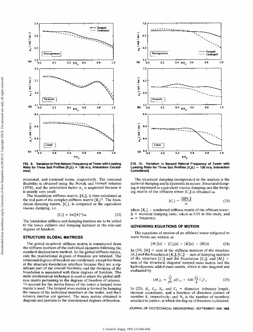
FIG. 9. Variation in First Natural Frequency of Tower with Loading FIG. 10. Variation in Second Natural Frequency of Tower withRatio for Three Soil Profiles £V.(L) = 100 mIs, Interaction Consid- Loading Ratio for Three Soil Profiles £V.(L) = 100 mIs, Interactionered] Considered]
STRUCTURE GLOBAL MATRICES
The foundation stiffness and damping matrices are to be addedto the tower stiffness and damping matrices at the relevantdegrees of freedom.
rotational, and torsional terms, respectively. The torsionalflexibility is obtained using the Novak and Howell solution(1978), and the interaction factor aT] is neglected because itis usually very small.
The foundation stiffness matrix, [Krl. is then calculated asthe real part of the complex stiffness matrix [Kr ]*. The foundation damping matrix, [Crl. is computed as the equivalentviscous damping, i.e.
GOVERNING EQUATIONS OF MOTION
(23)[C,] = 2~[K,]w
The structural damping incorporated in the analysis is thematerial damping and is hysteretic in nature. Structural damping is expressed as equivalent viscous damping and the damping matrix of the offshore tower [C,] is obtained as
where [Ks ] = condensed stiffness matrix of the offshore tower;~ = material damping ratio, taken as 0.01 in this study; andw = frequency.
The equations of motion of an offshore tower subjected towave forces are written as
(22)[Cr] = Im{[K]*}lw
(25)
The global structural stiffness matrix is constructed fromthe stiffness matrices of the individual elements following thestandard displacement method. In the global stiffness matrix,only the translational degrees of freedom are retained. Therotational degrees of freedom are condensed, except for thoseat the structure-foundation interface because they are a significant part of the overall flexibility and the damping of thefoundation is associated with these degrees of freedom. Thestatic condensation technique is used to attain the global stiffness matrix pertaining to the degrees of freedom of interest.To account for the inertia forces of the tower a lumped massmatrix is used. The lumped mass matrix is formed by lumpingthe masses of the individual members at the nodes, and theirrotatory inertias are ignored. The mass matrix obtained isdiagonal and pertains to the translational degrees of freedom.
[M,]{ii} + [Cb]{u} + [K]{u} = {Wet)} (24)
In (24), [K] = sum of the stiffness matrices of the structure[K,] and the foundation [Kr]; [Cb ] = sum of damping matricesof the structure [Cs ] and the foundation [Cd; and [M,] =sum of the structural diagonal lumped mass matrix and thehydrodynamic added mass matrix, which is also diagonal andevaluated by
Nn d~(M,,);; = k~l p(Cm - l)n 4" rkLk
In (25), dko L ko Sko and r k = diameter, tributary length,element coordinate, and a function of direction cosines ofmember k, respectively; and Nn is the number of membersattached to joint n, at which the degree of freedom i is located.
JOURNAL OF GEOTECHNICAL ENGINEERING / SEPTEMBER 1995/665
J. Geotech. Engrg. 1995.121:660-668.
Dow
nloa
ded
from
asc
elib
rary
.org
by
Uni
vers
ity o
f N
ew H
amps
hire
on
09/3
0/13
. Cop
yrig
ht A
SCE
. For
per
sona
l use
onl
y; a
ll ri
ghts
res
erve
d.
9~
1.0~..
8 IHomogeneous I -('0 .. IHomogeneous I -('110 0..,
FIG. 11. Variation in Foundation Damping Ratios of Tower with FIG. 12. Variation in Structural Damping Ratios of Tower withLoading Ratio for Three Soil Profiles [V.(L) = 100 mIs, Interaction Loading Ratio for Three Soil Profiles [V.(L) = 100 mIs, InteractionConsidered] Considered]
FREE-VIBRATION ANALYSIS
Setting the force vector {W(t)} to zero, the free-vibrationequations of motion are
where Re and 1m indicate the real and imaginary parts, respectively.
666 / JOURNAL OF GEOTECHNICAL ENGINEERING I SEPTEMBER 1995
The inertia coefficient eM is assumed to be constant with thevalue two, and p is the water density. {u}, {u}, and {u} are thevectors of structural displacements, velocities, and accelerations, respectively. Finally, the vector {W(t)} is the vector ofwave forces
A typical fixed offshore tower, shown in Fig. 8,is analyzedto illustrate the effect of soil structure interaction on its modalproperties. The tower is 122.0 m high and stands in 104.5 mof water. It is supported by 10 piles with an outer diameterof 1.45 m and a depth of 50 m. Six main piles extend throughthe main legs all the way to the top of the structure and fourskirt piles are cut off and welded at the level of the firstbracing. The tower is symmetric about both the X- and Zaxes. Only one quarter of the structure is idealized and twodifferent sets of boundary conditions are applied: (1) sway inthe X-direction, in this case X is the axis of symmetry and Zis the axis of antisymmetry; (2) torsional mode, in which bothX and Z are the axes of antisymmetry.
A parametric study is conducted to illustrate the effect offoundation nonlinearity and pile-soil-pile interaction on themodal properties of the tower. In this study, three differentsoil profiles are considered. They are characterized by constant, parabolic, or linear variation of soil shear-wave velocitywith depth. For all the results presented here, the deck massis 760 t, which represents 20.33% of the total mass of thestructure.
To explore the effect of soil nonlinearity and slippage andseparation at the soil-pile interface, the foundation stiffnessand damping constants are calculated for different loadinglevels at pile heads, P/Pu , as a ratio of pile capacities. Thesestiffness and damping constants are then used in the freevibration analysis.
Fig. 9 shows the variation in the first undamped and damped
EXAMPLE
(26)
(29)
[M]{u} + [C]{u} + [K]{u} = {O}
This homogeneous equation is solved for free-vibration modes,natural frequencies, and modal damping ratios using the complex eigenvalue analysis (Novak and EI Hifnawy 1983). Thisanalysis yields pairs of complex conjugate eigenvalues andpairs of complex eigenvectors. The complex eigenvalues canbe expressed in the form
(fL)I.2 = -SjW; ± iwJv'1 - s} (27)
From (27), the damped frequency wj can be obtained as
wi = Im[ fLj] (28)
and the modal damping ratio is given by
- Re[fLJSj = IfLJI
J. Geotech. Engrg. 1995.121:660-668.
Dow
nloa
ded
from
asc
elib
rary
.org
by
Uni
vers
ity o
f N
ew H
amps
hire
on
09/3
0/13
. Cop
yrig
ht A
SCE
. For
per
sona
l use
onl
y; a
ll ri
ghts
res
erve
d.
3.5 c:: 10y IHomogeneous I------------ ... 0
....... - - - -_ ...... ..::: 8
'"e
<>, OIl
~, .5 6,
~] 3.0
, , .g4=
3-0.:::..IHomogeneous I .., 2= - --- --------:::0 .------------------0
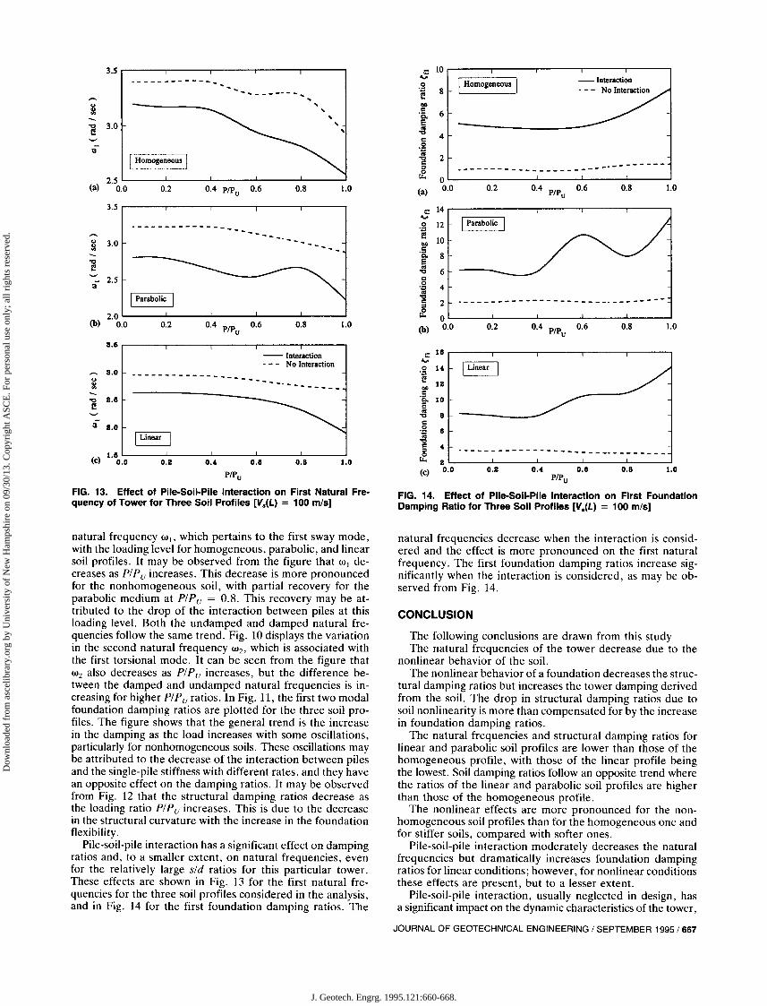
FIG. 13. Effect of Pile-Soil-Pile Interaction on First Natural Fre- FIG. 14. Effect of Pile-Soil-Pile Interaction on First Foundationquency of Tower for Three Soil Profiles [V.(L) = 100 m/s] Damping Ratio for Three Soil Profiles [V.(L) = 100 m/s]
natural frequency Wj, which pertains to the first sway mode,with the loading level for homogeneous, parabolic, and linearsoil profiles. It may be observed from the figure that WI decreases as PIPu increases. This decrease is more pronouncedfor the nonhomogeneous soil, with partial recovery for theparabolic medium at PIPu = 0.8. This recovery may be attributed to the drop of the interaction between piles at thisloading level. Both the undamped and damped natural frequencies follow the same trend. Fig. 10 displays the variationin the second natural frequency W2, which is associated withthe first torsional mode. It can be seen from the figure thatW2 also decreases as PIPu increases, but the difference between the damped and undamped natural frequencies is increasing for higher PIPu ratios. In Fig. 11, the first two modalfoundation damping ratios are plotted for the three soil profiles. The figure shows that the general trend is the increasein the damping as the load increases with some oscillations,particularly for nonhomogeneous soils. These oscillations maybe attributed to the decrease of the interaction between pilesand the single-pile stiffness with different rates, and they havean opposite effect on the damping ratios. It may be observedfrom Fig. 12 that the structural damping ratios decrease asthe loading ratio PIPu increases. This is due to the decreasein the structural curvature with the increase in the foundationflexibility.
Pile-soil-pile interaction has a significant effect on dampingratios and, to a smaller extent, on natural frequencies, evenfor the relatively large sid ratios for this particular tower.These effects are shown in Fig. 13 for the first natural frequencies for the three soil profiles considered in the analysis,and in Fig. 14 for the first foundation damping ratios. The
natural frequencies decrease when the interaction is considered and the effect is more pronounced on the first naturalfrequency. The first foundation damping ratios increase significantly when the interaction is considered, as may be observed from Fig. 14.
CONCLUSION
The following conclusions are drawn from this studyThe natural frequencies of the tower decrease due to the
nonlinear behavior of the soil.The nonlinear behavior of a foundation decreases the struc
tural damping ratios but increases the tower damping derivedfrom the soil. The drop in structural damping ratios due tosoil nonlinearity is more than compensated for by the increasein foundation damping ratios.
The natural frequencies and structural damping ratios forlinear and parabolic soil profiles are lower than those of thehomogeneous profile, with those of the linear profile beingthe lowest. Soil damping ratios follow an opposite trend wherethe ratios of the linear and parabolic soil profiles are higherthan those of the homogeneous profile.
The nonlinear effects are more pronounced for the nonhomogeneous soil profiles than for the homogeneous one andfor stiffer soils, compared with softer ones.
Pile-soil-pile interaction moderately decreases the naturalfrequencies but dramatically increases foundation dampingratios for linear conditions; however, for nonlinear conditionsthese effects are present, but to a lesser extent.
Pile-soil-pile interaction, usually neglected in design, hasa significant impact on the dynamic characteristics of the tower,
JOURNAL OF GEOTECHNICAL ENGINEERING 1SEPTEMBER 1995/667
J. Geotech. Engrg. 1995.121:660-668.
Dow
nloa
ded
from
asc
elib
rary
.org
by
Uni
vers
ity o
f N
ew H
amps
hire
on
09/3
0/13
. Cop
yrig
ht A
SCE
. For
per
sona
l use
onl
y; a
ll ri
ghts
res
erve
d.
even with the large spacing between piles, and should beconsidered.
ACKNOWLEDGMENTS
This research was supported by a research grant-in-aid from the Natural Sciences and Engineering Research Council of Canada, Ottawa,Canada.
APPENDIX. REFERENCES
American Petroleum Institute. (1991). "Recommended practice for planning, designing and constructing fixed offshore platforms." API Recommended Practice 2A (RP 2A), 19th Ed., Washington, D.C.
Bathe, K. J. (1982). Finite element procedures in engineering analysis.Prentice-Hall, Inc., Englewood Cliffs, N.J.
EI-Marsafawi, H., Kaynia, A. M., and Novak, M. (1992). "The superposition approach to pile group dynamics. Piles under dynamic loads."Geotech. Spec. Publ. No. 34, ASCE, New York, N.Y., 114-135.
EI Naggar, M. H. (1994). "Nonlinear analysis of piles with applicationto offshore tower response," PhD thesis, Univ. of Western Ontario,London, Ontario, Canada.
EI Naggar, M. H., and Novak, M. (1994a). "Nonlinear model for dynamic axial pile response." J. Geotech. Engrg., ASCE, 120(2), 308329.
EI Naggar, M. H., and Novak, M. (l994b). "Nonlinear axial interaction
668/ JOURNAL OF GEOTECHNICAL ENGINEERING / SEPTEMBER 1995
in pile dynamics." J. Geotech. Engrg.. ASCE, 120(4).678-696.Gazetas, G., and Dobry, R. (1984). "Simple radiation damping model
for piles and footings." J. Engrg. Mech .. ASCE. 110(6),937-956.Kondner. R. L. (1963). "Hyperbolic stress strain response: cohesive
soils." J. Soil Mech. and Found. Div., ASCE, 89(1),115-143.Makris. N., and Gazetas. G. (1992). "Dynamic pile-soil-pile interaction.
Part II: lateral and seismic response." J. Earthquake Engrg. and Struct.Dynamics, 21(2), 145-162.
Novak, M. (1977). "Vertical vibration of floating piles." 1. Engrg. Mech ..ASCE, 103(1), 153-167.
Novak, M., and EI Hifnawy. L. (1983). "Effect of soil structure interaction on damping of structures." 1. Earthquake Engrg. and Struct.Dynamics, II(Sep.). 595-621.
Novak, M., and Howell, J. I. (1978). "Dynamic response of pile foundations in torsion." 1. Geotech. Engrg.. ASCE, 104(5), 535-552.
Novak, M.• Nogami, T.. and Aboul-Ella. F. (1978). "Dynamic soil reactions for plane strain case." 1. Engrg. Mech., ASCE. 104(4).953959.
Novak, M., and Sheta, M. (1980). "Approximate approach to contactproblems of piles." Proc., ASCE, Nat. Convention. "Dynamic Response of Pile Foundations: Analytical Aspects," ASCE, New York,N.Y., 53-79.
Poulos, H. G. (1971). "Behaviour of laterally loaded piles: II-pile groups."J. Soil Mech. and Found. Div.. ASCE. 97(5). 733-751.
Winkler, E. (1867). Die Lehre vander Elastizitat und Festigkeit. Dominicus. Prague. Czech Republic.