General rights Copyright and moral rights for the publications made accessible in the public portal are retained by the authors and/or other copyright owners and it is a condition of accessing publications that users recognise and abide by the legal requirements associated with these rights. Users may download and print one copy of any publication from the public portal for the purpose of private study or research. You may not further distribute the material or use it for any profit-making activity or commercial gain You may freely distribute the URL identifying the publication in the public portal If you believe that this document breaches copyright please contact us providing details, and we will remove access to the work immediately and investigate your claim. Downloaded from orbit.dtu.dk on: Apr 28, 2020 Effect of ionic contamination on climatic reliability of printed circuit board assemblies Verdingovas, Vadimas; Jellesen, Morten Stendahl; Ambat, Rajan Published in: Proceedings of the European Corrosion Congress 2012 Publication date: 2012 Link back to DTU Orbit Citation (APA): Verdingovas, V., Jellesen, M. S., & Ambat, R. (2012). Effect of ionic contamination on climatic reliability of printed circuit board assemblies. In Proceedings of the European Corrosion Congress 2012: Safer world through better corrosion control
Transcript
General rights Copyright and moral rights for the publications made accessible in the public portal are retained by the authors and/or other copyright owners and it is a condition of accessing publications that users recognise and abide by the legal requirements associated with these rights.
Users may download and print one copy of any publication from the public portal for the purpose of private study or research.
You may not further distribute the material or use it for any profit-making activity or commercial gain
You may freely distribute the URL identifying the publication in the public portal If you believe that this document breaches copyright please contact us providing details, and we will remove access to the work immediately and investigate your claim.
Downloaded from orbit.dtu.dk on: Apr 28, 2020
Effect of ionic contamination on climatic reliability of printed circuit board assemblies
Verdingovas, Vadimas; Jellesen, Morten Stendahl; Ambat, Rajan
Published in:Proceedings of the European Corrosion Congress 2012
Publication date:2012
Link back to DTU Orbit
Citation (APA):Verdingovas, V., Jellesen, M. S., & Ambat, R. (2012). Effect of ionic contamination on climatic reliability ofprinted circuit board assemblies. In Proceedings of the European Corrosion Congress 2012: Safer world throughbetter corrosion control
The effect of NaCl and weak organic acids (WOAs) in “no-clean” wave solder flux residues was studied on electrochemical migration (ECM), leakage current, and corrosion on surface mount chip capacitors using a test printed circuit board assembly (PCBA) substrate having known chip components. The investigations were performed under environmental conditions varying from non-condensation with 60% RH at 25°C to near to condensation with 98% RH at 25°C, and full condensation conditions. Near to condensation and full condensation conditions have been established by (i) lowering the temperature of PCBA while keeping the temperature and relative humidity constant inside the climatic chamber and (ii) applying single micro-droplets of water on the surface mount chip capacitors. Water layer formation on the PCBA was observed in-situ by introducing a video camera inside the climatic chamber. The ECM probability testing under droplet condition showed dependency on the type and amount of ionic contamination. Climatic testing of the test PCBAs pre-contaminated with NaCl and solder flux residues showed the importance of hygroscopic nature of ionic contamination to corrosion and leakage current due to water adsorption on the surface.
1. INTRODUCTION
The climatic reliability of electronic circuits is becoming an important issue in recent years due to increased requirements for long term reliability and the harsher environments in which electronics has to operate [1–3]. The reliability of electronic devices has become more sensitive to the environmental conditions and presence of ionic contamination due to ever-increasing use of high frequency in high-density interconnection assemblies, increasing package component densities and decreasing component stand offs [4–6].
The electronics design, as well as the nature of the environment, is critical because corrosion failures in the integrated circuits and electronic components can occur even at extremely low levels of moisture and contamination. The presence of ionic contamination on a surface of a printed circuit board assembly (PCBA) acts as an accelerating factor for corrosion. Most ionic residues are hygroscopic and assist the water adsorption to the surface, which enables the dissolution of ionic contamination thereby reducing the surface insulation resistance and increasing the leak currents on the PCBA. An electrochemical process that occurs on metals covered by a thin film of electrolyte is often primarily responsible for the damage to the electrical and electronic components that can lead to premature failures [1,7,8].
Moisture condensation on a surface in humid environments depends on a number of factors including relative humidity (RH), temperature differences between the condensing surface and environment, surface roughness, porosity, and finally the presence of hygroscopic contaminants [9]. This paper discusses the effect of NaCl and a specific wave solder flux residue on the corrosion behavior, ECM migration probability, and leakage current investigated using test specimens such as surface mount components and a SIR comb pattern biased at DC voltage and exposed under various environmental conditions. The climatic condition under which the test vehicles were exposed vary from dry at 60% RH and 25°C to full condensation, when a visible layer of water is formed on the surface. The condensation condition is established by reducing the temperature of the PCB, while keeping the climatic conditions constant. The effect of type and level of ionic contamination on the ECM probability under full condensation conditions is studied by applying single micro-droplets of water on the surface mount chip capacitors.
2. MATERIALS AND EXPERIMENTAL METHODS
2.1 Contaminants Two types of contaminants have been used for the investigations, namely: (i) NaCl which dissolved into water acts as a strong electrolyte and is used to define the equivalent contamination levels on PCBAs as described in IPC standards, and (ii) Cobar 390-RX-HT, a type of “no-clean” weak organic acid (WOA) based wave solder flux residue, which is also a commonly found contamination on PCBAs. The solid content of this solder flux as determined by weight measurement is approx. 3 wt.% and the content of WOAs as determined by ion chromatography is approx. 2 wt.%. In this work, the flux residues consist of solid residues which include resin and WOAs. The solid flux residues and NaCl were dissolved into de-ionized water with resistivity in the range between 2 MΩ·cm and 2.5 MΩ·cm at room temperature. The electrolytes were used to pre-contaminate the PCBs and components prior to testing.
2.2 Components The components used for ECM probability testing under droplet condition were size 0805 10 nF multilayer ceramic chip capacitors. The average distance between the terminals of the capacitors is 1 mm. The electrode terminals are made of pure tin with traces of lead (< 2 wt.%).
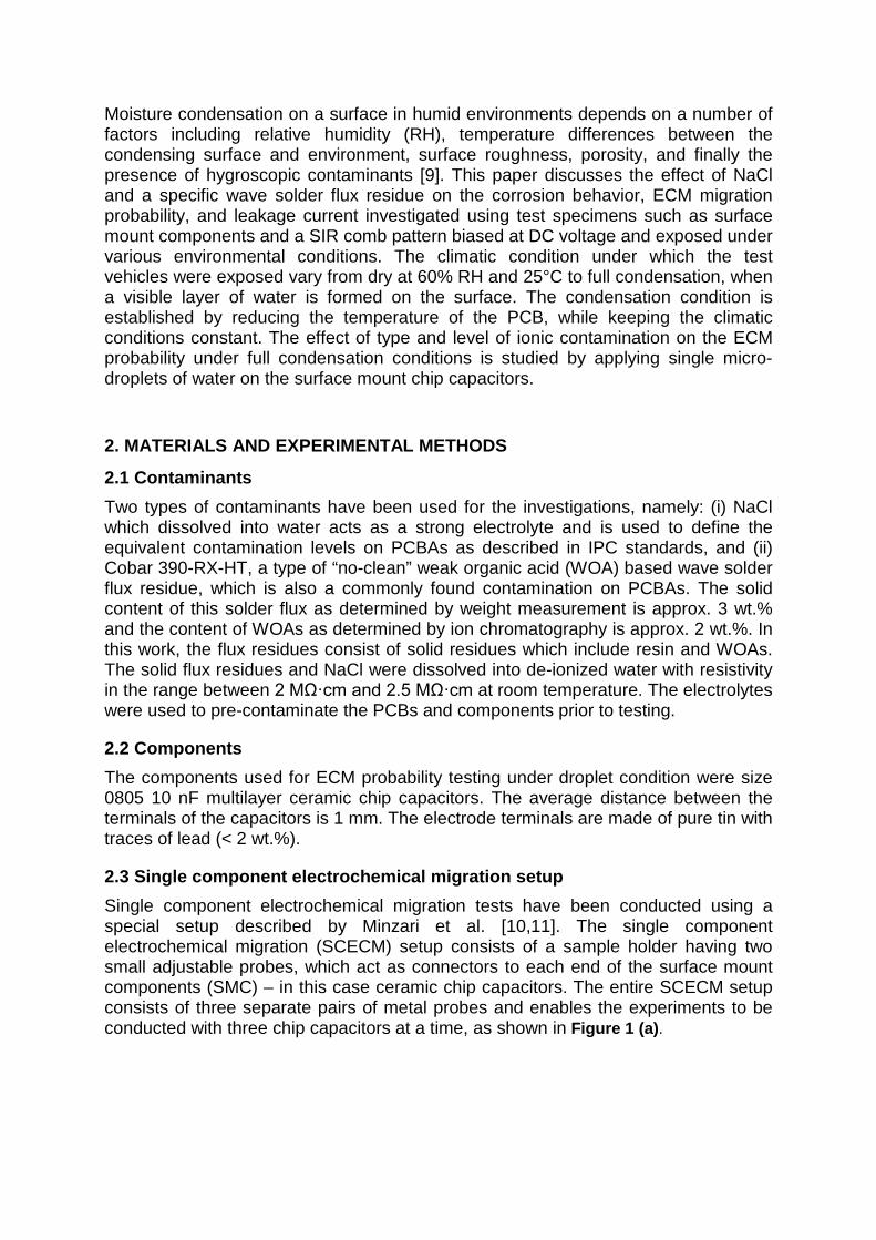
2.3 Single component electrochemical migration setup Single component electrochemical migration tests have been conducted using a special setup described by Minzari et al. [10,11]. The single component electrochemical migration (SCECM) setup consists of a sample holder having two small adjustable probes, which act as connectors to each end of the surface mount components (SMC) – in this case ceramic chip capacitors. The entire SCECM setup consists of three separate pairs of metal probes and enables the experiments to be conducted with three chip capacitors at a time, as shown in Figure 1 (a).
Figure 1: Single component electrochemical migration setup
The ECM probability testing on the single components was done by placing a micro droplet of electrolyte at a desirable concentration on top of the surface mount components. The current was measured between the terminals of the components which are bridged via the droplet of electrolyte solution and biased at DC voltage in the range of 1 V – 25 V using an in-house built multi-channel multiplexer unit called “CELCORR test PCB set up”, described elsewhere [12]. The leak current followed by the current increase due to ECM (electric short due to dendrite formation) was measured with a 1 µA resolution ammeter connected in the circuit via a two switch system. The sampling rate for the leakage current reading was set to 1 s. The experiments were carried out under ambient conditions: temperature 23.5°C – 24.5°C, relative humidity 30% – 40%.
For tests carried out under non-condensation conditions, the water was evaporated, hereby leaving the components pre-contaminated at known levels. The volume of droplets was selected in accordance with the surface area of the component to provide a fixed level of contamination in terms of µg/cm2 for comparison with IPC J-STD-001 standard. A relationship of 1 µl of solution over 1 mm2 area has been used to fix the level in µg/cm2, which enabled an equivalent between g/l and µg/cm2 with a ratio of 1:100. The experiments were carried out using a “BioLogic VSP” multichannel potentiostat, Bio-Logic Instruments, France, having 0 – 20 V compliance voltage and 1 nA resolution.
2.4 Test printed circuit board The test PCB is made on a FR4 laminate in accordance with IPC‐4101/21 having a size of 168 x 112.4 mm and thickness of 1.6 mm. The test PCB system consists of known SMCs like chip capacitors and chip resistors soldered in parallel rows of 10 components and two SIR comb patterns (one of the SIR patterns is placed under the solder mask as reference). However, for investigations reported in this work only two channels of the test PCB systems were analyzed, namely the SMC with size 0805 100nF ceramic chip capacitors and the SIR comb pattern above the solder mask. The SIR pattern was made of lead free HASL finish with an overall surface area of 13 x 25 mm with 0.3 mm pitch size for the comb pattern. The overlapping area is 10.8 mm in height and there are 42 sets of common overlap giving 453.6 mm as the total length of opposing faces. The ratio of total length of opposing faces and spacing of all segments gives the nominal square count, which is 1512 for this SIR comb pattern. It is in contrast with B-36 board comb patterns having 3538 squares and B-24 having 1020 squares. The sensitivity of SIR pattern increases with increasing number of squares.
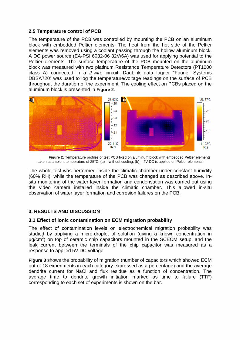
2.5 Temperature control of PCB The temperature of the PCB was controlled by mounting the PCB on an aluminum block with embedded Peltier elements. The heat from the hot side of the Peltier elements was removed using a coolant passing through the hollow aluminum block. A DC power source (EA-PSI 6032-06 32V/6A) was used for applying potential to the Peltier elements. The surface temperature of the PCB mounted on the aluminum block was measured with two platinum Resistance Temperature Detectors (PT1000 class A) connected in a 2-wire circuit. DaqLink data logger “Fourier Systems DBSA720” was used to log the temperature/voltage readings on the surface of PCB throughout the duration of the experiment. The cooling effect on PCBs placed on the aluminum block is presented in Figure 2.
Figure 2: Temperature profiles of test PCB fixed on aluminum block with embedded Peltier elements
taken at ambient temperature of 25°C: (a) – without cooling; (b) – 4V DC is applied on Peltier elements
The whole test was performed inside the climatic chamber under constant humidity (60% RH), while the temperature of the PCB was changed as described above. In-situ monitoring of the water layer formation and condensation was carried out using the video camera installed inside the climatic chamber. This allowed in-situ observation of water layer formation and corrosion failures on the PCB.
3. RESULTS AND DISCUSSION
3.1 Effect of ionic contamination on ECM migration probability The effect of contamination levels on electrochemical migration probability was studied by applying a micro-droplet of solution (giving a known concentration in µg/cm2) on top of ceramic chip capacitors mounted in the SCECM setup, and the leak current between the terminals of the chip capacitor was measured as a response to applied 5V DC voltage.
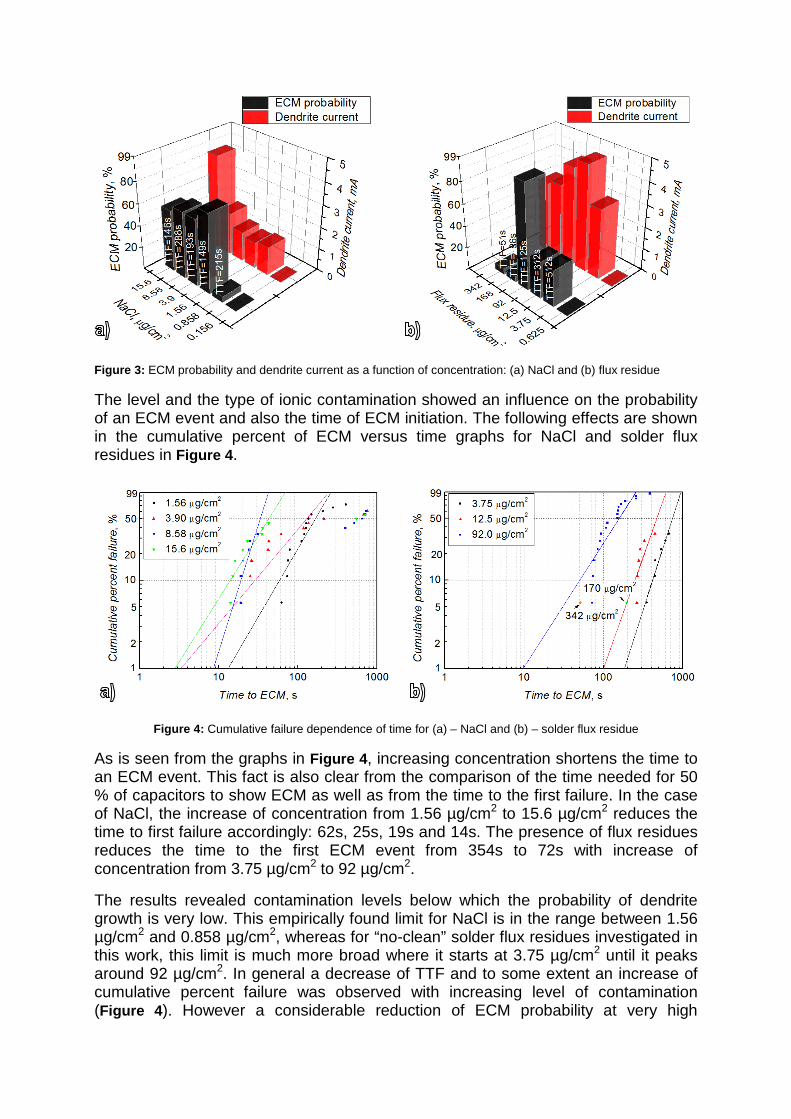
Figure 3 shows the probability of migration (number of capacitors which showed ECM out of 18 experiments in each category expressed as a percentage) and the average dendrite current for NaCl and flux residue as a function of concentration. The average time to dendrite growth initiation marked as time to failure (TTF) corresponding to each set of experiments is shown on the bar.
Figure 3: ECM probability and dendrite current as a function of concentration: (a) NaCl and (b) flux residue
The level and the type of ionic contamination showed an influence on the probability of an ECM event and also the time of ECM initiation. The following effects are shown in the cumulative percent of ECM versus time graphs for NaCl and solder flux residues in Figure 4.
Figure 4: Cumulative failure dependence of time for (a) – NaCl and (b) – solder flux residue
As is seen from the graphs in Figure 4, increasing concentration shortens the time to an ECM event. This fact is also clear from the comparison of the time needed for 50 % of capacitors to show ECM as well as from the time to the first failure. In the case of NaCl, the increase of concentration from 1.56 µg/cm2 to 15.6 µg/cm2 reduces the time to first failure accordingly: 62s, 25s, 19s and 14s. The presence of flux residues reduces the time to the first ECM event from 354s to 72s with increase of concentration from 3.75 µg/cm2 to 92 µg/cm2.
The results revealed contamination levels below which the probability of dendrite growth is very low. This empirically found limit for NaCl is in the range between 1.56 µg/cm2 and 0.858 µg/cm2, whereas for “no-clean” solder flux residues investigated in this work, this limit is much more broad where it starts at 3.75 µg/cm2 until it peaks around 92 µg/cm2. In general a decrease of TTF and to some extent an increase of cumulative percent failure was observed with increasing level of contamination (Figure 4). However a considerable reduction of ECM probability at very high
concentrations of contamination can be seen for WOAs in the flux residue which is in contrast with NaCl. This behavior is attributed to decreased stability of tin ions in the solution.
Figure 5 shows the morphology of the dendrite after migration for NaCl and flux residue as a function of concentration. For NaCl, the probability of dendrite growth increases rapidly above a concentration of 0.858 µg/cm2. Below this level, the migration probability is low, probably due to the low dissolution of tin. Typical surface morphology of a component at 0.156 µg/cm2 of NaCl shows very few corrosion products (appearing white in the image). However as the concentration of chloride increases, dendrites start appearing, and at very high concentration levels a mixture of dendrites and white precipitate species can be seen. At high chloride levels, the probability of ECM is also slightly reduced due to the large amounts of tin ions in the solution which leads to heavy precipitation, reducing the chance for dendrite growth as reported by Minzari et al. [13]. The precipitated species can be hydroxides of tin namely Sn(OH)4 and/or Sn(OH)2, although intermediate hydroxyl chloride species are also possible [14].
Figure 5: Size 0805 capacitors after SCECM testing at 5 V DC; pictures corresponding to NaCl and solder flux
residues are shown in the images. Anode terminal is on the right and cathode on the left side
Typical optical micrographs of the tested components with flux residue (Figure 5) shows that the level of corrosion is negligible at lower concentrations; however, at 92 µg/cm2, the surface of the component shows a clear dendrite mixed with some hydroxides. The appearance of ECM at flux residue concentrations 3.75 µg/cm2 – 92 µg/cm2 is similar to the appearance of ECM observed with NaCl. Light optical microscope images revealed the dendrites (dark grey color) bridging the terminals and the tin hydroxides (white color).
Further increase in flux residue concentrations caused only a low probability of migration (Figure 3 (b)), while the component shown in Figure 5 shows heavy corrosion of the anode terminal, but no dendrites or precipitation of tin hydroxides as was seen in the case of NaCl. This appearance might indicate that the pH level of solution was moved towards the acidic area due to the high levels of weak organic acids in the flux residue and therefore the precipitation of tin hydroxides was
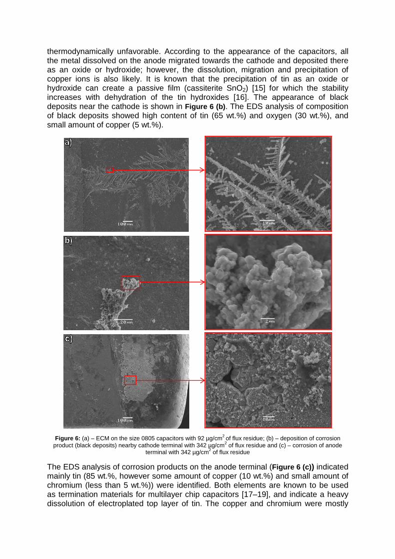
thermodynamically unfavorable. According to the appearance of the capacitors, all the metal dissolved on the anode migrated towards the cathode and deposited there as an oxide or hydroxide; however, the dissolution, migration and precipitation of copper ions is also likely. It is known that the precipitation of tin as an oxide or hydroxide can create a passive film (cassiterite SnO2) [15] for which the stability increases with dehydration of the tin hydroxides [16]. The appearance of black deposits near the cathode is shown in Figure 6 (b). The EDS analysis of composition of black deposits showed high content of tin (65 wt.%) and oxygen (30 wt.%), and small amount of copper (5 wt.%).
Figure 6: (a) – ECM on the size 0805 capacitors with 92 µg/cm2 of flux residue; (b) – deposition of corrosion
product (black deposits) nearby cathode terminal with 342 µg/cm2 of flux residue and (c) – corrosion of anode terminal with 342 µg/cm2 of flux residue
The EDS analysis of corrosion products on the anode terminal (Figure 6 (c)) indicated mainly tin (85 wt.%, however some amount of copper (10 wt.%) and small amount of chromium (less than 5 wt.%)) were identified. Both elements are known to be used as termination materials for multilayer chip capacitors [17–19], and indicate a heavy dissolution of electroplated top layer of tin. The copper and chromium were mostly
identified on the very edges of the anode terminal, where the dissolution rate of metal is expected to be the highest.
Overall the results presented above indicate that both NaCl and flux residues can accelerate the ECM considerably. The ECM probability is dependent on the contamination type and the level it is present on the PCBA. In general the ECM probability is increasing with increasing level of contamination, however above a certain level, dependent on the tin ions stability in the solution can be reduced drastically. The latter was the case with WOAs in the flux residues. SEM/EDX analysis of the capacitors with 342 µg/cm2 of flux residues revealed heavy deterioration of anode terminal and corrosion products on the cathode terminal indicating the presence of severe conditions; however, conditions unfavorable for ECM.
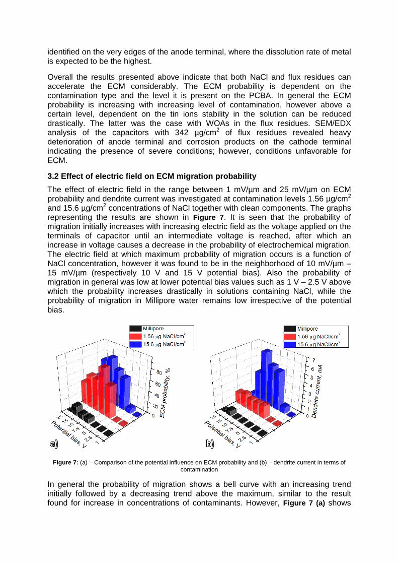
3.2 Effect of electric field on ECM migration probability The effect of electric field in the range between 1 mV/µm and 25 mV/µm on ECM probability and dendrite current was investigated at contamination levels 1.56 µg/cm2 and 15.6 µg/cm2 concentrations of NaCl together with clean components. The graphs representing the results are shown in Figure 7. It is seen that the probability of migration initially increases with increasing electric field as the voltage applied on the terminals of capacitor until an intermediate voltage is reached, after which an increase in voltage causes a decrease in the probability of electrochemical migration. The electric field at which maximum probability of migration occurs is a function of NaCl concentration, however it was found to be in the neighborhood of 10 mV/µm – 15 mV/µm (respectively 10 V and 15 V potential bias). Also the probability of migration in general was low at lower potential bias values such as 1 V – 2.5 V above which the probability increases drastically in solutions containing NaCl, while the probability of migration in Millipore water remains low irrespective of the potential bias.
Figure 7: (a) – Comparison of the potential influence on ECM probability and (b) – dendrite current in terms of
contamination
In general the probability of migration shows a bell curve with an increasing trend initially followed by a decreasing trend above the maximum, similar to the result found for increase in concentrations of contaminants. However, Figure 7 (a) shows
that the effect of contamination is more pronounced, especially from Millipore water to 1.56 µg/cm2 chloride solutions. The dendrite current also shows a similar behavior except for a large increase of dendrite current at 15.6 µg/cm2 conditions. This indicates the formation of thick dendrites, unlike in other cases. It shows that increased contamination increases the dissolution rate of the metal, which consequently forms thicker and more branched dendrites containing more metal and hydroxide precipitation. The high amount of metal content in the dendrites increases the current leaking through. However, as the potential increases, the probability of migration decreases, which also correlates with a decrease in the dendrite current. This is due to the fact that the rate of dissolution of tin increases with an increase in potential bias similar to increase in contamination. This leads to precipitation of the hydroxide species, while the heavy gas evolution at the anode and cathode also inhibit the formation of dendrites. Minzari et al. [11] have reported similar phenomenon with increase in potential bias or contamination level.
The visual and SEM/EDS inspection of ECM and corrosion revealed the precipitation of tin hydroxides, but no formation of dendrites at potentials below 2.5 V. At 1 V potential difference, the precipitation of hydroxides could be seen in the middle of the capacitor, indicating the homogenous pH change from acidic to alkaline and neutral in the middle. The diffusion of the dissolved metal-ions is mainly dependent on the effective electrical field strength [20], therefore it can be assumed that the electric field strength was insufficient for the tin hydroxides to reach the cathode terminal of the capacitor. It has also been reported that the threshold electric field under which ECM will not occur is below 1 mV/µm [21].
The increase of anode terminal corrosion and hydroxide precipitation rate was observed with increasing applied potential bias in the range between 5 V and 10 V. Apart from that, no significant change of appearance of corrosion and dendrite structure was observed with light optical microscopy or with SEM/EDS. However at potentials above 15 V, the positively biased terminals were heavily corroded. The measurements at 25 V potential revealed that no dendrites are formed, although the anode is heavily corroded, indicating a high rate of tin dissolution. The discrete deposits, probably tin hydroxides and oxides, at this condition can be seen. This can be attributed to insufficiently alkaline conditions near the cathode to sustain the presence of (Sn(OH)6)2-, which could be reduced at the cathode. As the potential bias increases due to the dissolution of large amounts of tin ions, the alkaline boundary for the formation of (Sn(OH)6)2- becomes unsustainable, as reported by Minzari et al. [11].
The results have shown that at potential below 2.5 V the probability of observing ECM on size 0805 capacitors under wet conditions within 15 minutes is very low but increases with increasing potential until a certain limit. The highest ECM rate was observed between 7.5 V – 10 V potential. In spite of increasing anode terminal dissolution rate with further increase of applied voltage, the probability of ECM events and dendrite formation decreases.
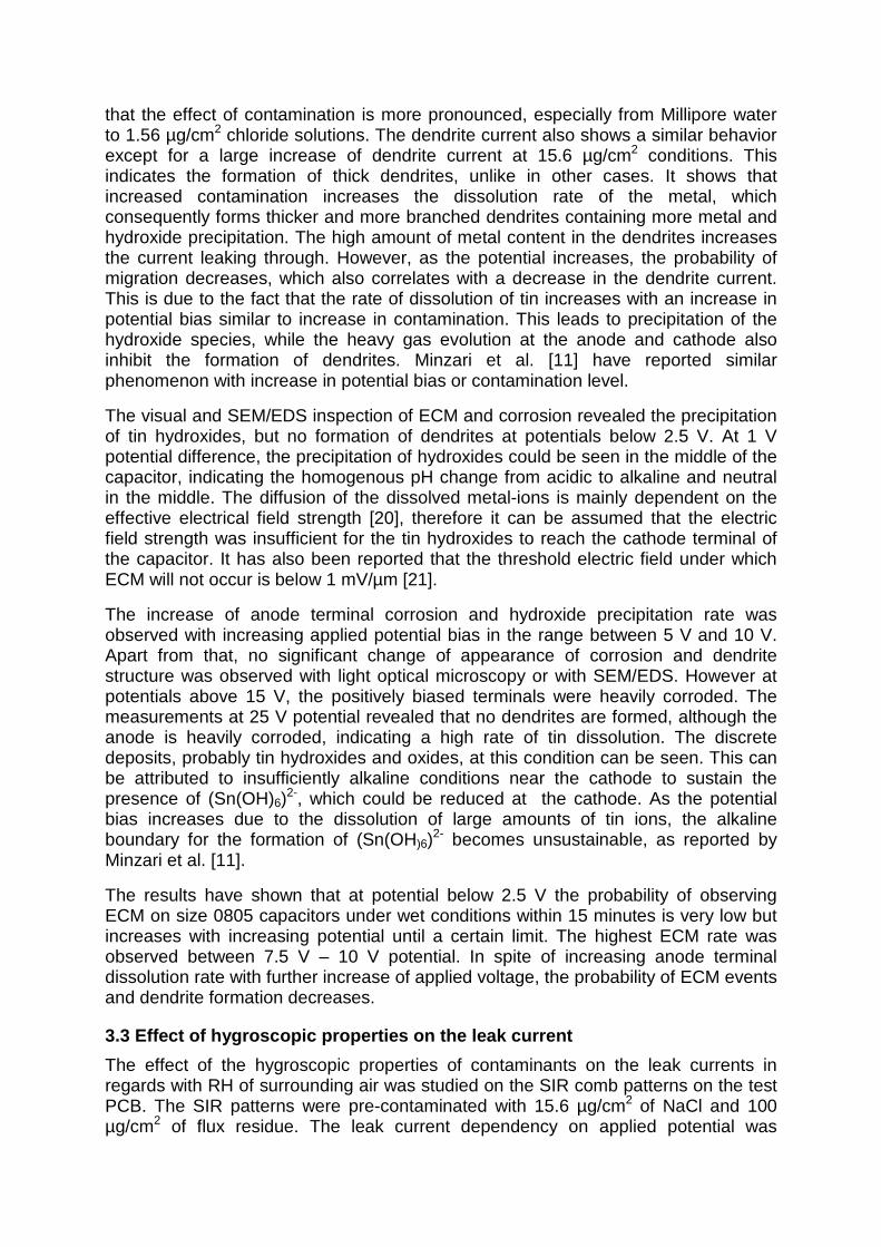
3.3 Effect of hygroscopic properties on the leak current The effect of the hygroscopic properties of contaminants on the leak currents in regards with RH of surrounding air was studied on the SIR comb patterns on the test PCB. The SIR patterns were pre-contaminated with 15.6 µg/cm2 of NaCl and 100 µg/cm2 of flux residue. The leak current dependency on applied potential was
measured in the range from 0 V to 9 V with a sweep rate of 2 mV/s. The measured voltammetry curves as a function of RH are presented in Figure 8. The temperature during the experiment was kept constant at 25°C.
Figure 8: Leakage current as a function of applied potential and relative humidity: (a) – solder flux residue and (b)
– NaCl and non-contaminated surface
The presence of flux residues (Cobar 390-RX-HT) is less effective in generating leakage current at all humidity levels compared to NaCl. With the increase of relative humidity from 60% to 98%, the leak current measured on the SIR comb pattern pre-contaminated with the flux residues has increased somewhat more than two orders of magnitude and no ECM initiation has been observed after the testing. Whereas in case on NaCl a more than four orders of magnitude increase in leak current has been observed when the relative humidity exceeded 80 % value. The observation of considerable increase of leak current is assumed to be an indication of NaCl dissolution and water layer formation on the SIR pattern. According to Kohler theory and Pöschl study on sodium chloride interaction with water vapour, the hygroscopic properties of NaCl enables adsorption of water molecules at RH around 75% [22]. The optical inspection of SIR comb pattern after the experiment revealed dendrite growth between the adjacent conductive lines. The increase of leakage current with increase of RH from 60% to 98%, measured on the non-contaminated SIR pattern was in scale of nA and negligible, indicating an importance of PCBA cleanliness for climatic reliability of electronics.
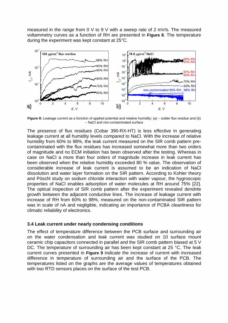
3.4 Leak current under nearly condensing conditions The effect of temperature difference between the PCB surface and surrounding air on the water condensation and leak current was studied on 10 surface mount ceramic chip capacitors connected in parallel and the SIR comb pattern biased at 5 V DC. The temperature of surrounding air has been kept constant at 25 °C. The leak current curves presented in Figure 9 indicate the increase of current with increased difference in temperature of surrounding air and the surface of the PCB. The temperatures listed on the graphs are the average values of temperatures obtained with two RTD sensors places on the surface of the test PCB.
Figure 9: Leakage current measured on test PCB biased at 5 V DC (a) – SIR comb pattern and (b) – 10 ceramic
chip capacitors size 0805 connected in parallel
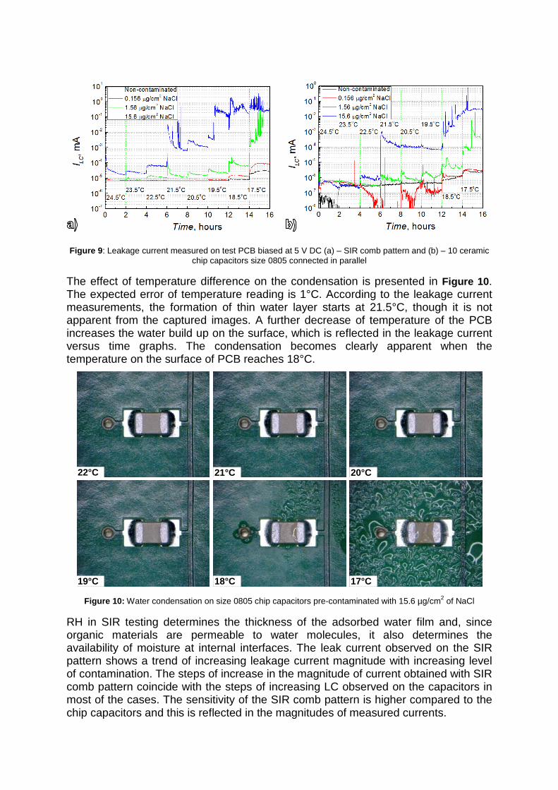
The effect of temperature difference on the condensation is presented in Figure 10. The expected error of temperature reading is 1°C. According to the leakage current measurements, the formation of thin water layer starts at 21.5°C, though it is not apparent from the captured images. A further decrease of temperature of the PCB increases the water build up on the surface, which is reflected in the leakage current versus time graphs. The condensation becomes clearly apparent when the temperature on the surface of PCB reaches 18°C.
Figure 10: Water condensation on size 0805 chip capacitors pre-contaminated with 15.6 µg/cm2 of NaCl
RH in SIR testing determines the thickness of the adsorbed water film and, since organic materials are permeable to water molecules, it also determines the availability of moisture at internal interfaces. The leak current observed on the SIR pattern shows a trend of increasing leakage current magnitude with increasing level of contamination. The steps of increase in the magnitude of current obtained with SIR comb pattern coincide with the steps of increasing LC observed on the capacitors in most of the cases. The sensitivity of the SIR comb pattern is higher compared to the chip capacitors and this is reflected in the magnitudes of measured currents.
22°C 21°C 20°C
19°C 18°C 17°C
For the non-contaminated condition, the increase of current is very little and it occurs during the last two steps, when the temperature difference between the surrounding air and PCB is sufficient enough for water condensation to occur. The increase of leakage current at 0.156 µg/cm2 of NaCl occurs at the same steps as it was on a non-contaminated surface, but with slightly higher magnitude of current.
Ionic contamination reduces the critical RH value and increases the leakage currents, as was shown by these experiments. A considerable increase of leak current is detected at concentrations starting from 1.56 µg/cm2. A substantial increase of leakage current is observed at complete condensation conditions (very last steps). However at concentrations above 1.56 µg/cm2, the critical RH for condensation is reduced to around 75% for both SIR and capacitors.
4. CONCLUSIONS
1. ECM probability for chip capacitor used in this investigation under droplet condition showed that it is a function of the type and amount of contamination, while the effect was different for NaCl and flux residue. In general increased contamination level caused increased occurrence of ECM and reduced time of initiation. However, at very high concentrations of contamination, ECM probability decreased, which is attributed to decreased stability of tin ions in solution.
2. The empirically found limit for low ECM probability for NaCl is in the range 1.56 µg/cm2 – 0.858 µg/cm2, This is lower than the IPC limit of 1.56 µg/cm2. Corresponding values for no-clean flux used in this investigation is more broad with ECM probability peaks around 92 µg/cm2.
3. Effect of increased electric field (potential bias) on ECM was in general similar to the effect of increased contamination level indicating that the effect is based on the influence on tin dissolution and stability of tin ions irrespective of how this is accelerated. The peak values of ECM probability at 1.56 µg/cm2 and 15.6 µg/cm2 of NaCl are respectively observed under 7.5 mV/µm and 10 V mV/µm electric field.
4. From the hygroscopic point of view, the presence of flux residues used in this work is less critical for humidity adsorption than NaCl. A steady increase of leakage current, however below the level typical to dendrite growth was observed with increasing RH on the SIR comb pattern pre-contaminated with flux residues. In case of NaCl a considerable increase of leakage current, followed by dendrite growth was observed at RH above 80%.
5. Test by cooling the PCB showed that the presence of hygroscopic contaminants reduces the critical RH for moisture condensation and is followed with increase of leak currents under lower relative humidity. The magnitude of leak current increases with increase of amount of ionic contamination – in this case NaCl.
5. ACKNOWLEDGMENTS Current research has been conducted as part of the CELCORR/CreCon consortium (www.celcorr.com) and authors acknowledge the funding from the consortium partners and for their commitment and help.
6. REFERENCES [1] J. Henriksen, R. Hienonen, T. Imrell, C. Leygraf, and L. Sjögren, Corrosion of electronics (A
handbook based on experiences from Nordic research project). Swedish Corrosion Institute, 1991, p. 86.
[2] H. Schweigart, “Humidity and pollution effects on electronic equipment,” CEEES Publication, 2001.
[3] J. D. Sinclair, T. B. Laboratories, M. Hill, C. J. Weschler, H. C. Shields, and R. Bank, “Deposition of Airborne Sulfate , Nitrate , and Chloride Salts as It Relates to Corrosion of Electronics,” vol. 137, no. 4, pp. 1200-1206, 1990.
[4] B. Kanegsberg and E. Kanegsberg, Handbook for Critical Cleaning. Applications, processes, and controls, 2nd ed. CRC Press, 2011, p. 524.
[5] D. Pauls, “Residues in printed wiring boards and assemblies,” pp. 32-41, 2000. [6] R. B. Comizzoli, C. A. Jankoski, G. A. Peins, L. A. Psota-Kelty, D. J. Siconolfi, and J. D.
Sinclair, “Reliability of Electronics in Harsh Environments: Electrical Leakage and Corrosion Caused by Hygroscopic Pollutant Particles,” Corrosion and Reliability of Electronic Materials and Devices, Proceedings, vol. 99, no. 29, pp. 186-193, 1999.
[7] R. Hienonen and R. Lahtinen, “Corrosion and climatic effects in electronics,” Vtt Publications, 2007.
[8] C. Leygraf, “Atmospheric Corrosion,” in Encyclopedia of Electrochemistry, Wiley-VCH Verlag GmbH & Co. KGaA, 2007.
[9] G. H. Findenegg and S. Herminghaus, “Wetting: statics and dynamics,” Current Opinion in Colloid & Interface Science, vol. 2, no. 3, pp. 301-307.
[10] D. Minzari, F. B. Grumsen, M. S. Jellesen, P. Møller, and R. Ambat, “Electrochemical migration of tin in electronics and microstructure of the dendrites,” Corrosion Science, vol. 53, no. 5, pp. 1659-1669, May 2011.
[11] D. Minzari, M. S. Jellesen, P. Møller, and R. Ambat, “On the electrochemical migration mechanism of tin in electronics,” Corrosion Science, vol. 53, no. 10, pp. 3366-3379, Oct. 2011.
[12] D. Minzari, “Doctoral Thesis, ‘Investigation of Electronic Corrosion Mechanisms’,” Technical University of Denmark, 2010.
[13] D. Minzari, M. S. Jellesen, P. Møller, P. Wahlberg, and R. Ambat, “Electrochemical Migration on Electronic Chip Resistors in Chloride Environments,” vol. 9, no. 3, pp. 392-402, 2009.
[14] M. Drogowska, L. Brossard, and H. Menard, “Influence of temperature on the electro-dissolution of tin in NaCl aqueous solution at pH4,” Journal of Applied Electrochemistry, vol. 20, no. 1, pp. 150-156, Jan. 1990.
[15] H. H. Hassan and K. Fahmy, “Pitting Corrosion of Tin by Acetate Anion in Acidic Media,” Microscope, vol. 3, pp. 29 - 43, 2008.
[16] S. S. Abdel Rehim, S. M. Sayyah, and M. M. El Deeb, “Corrosion of tin in citric acid solution and the effect of some inorganic anions,” Materials Chemistry and Physics, vol. 80, no. 3, pp. 696-703, Jun. 2003.
[17] T. Williams, The circuit designer’s companion, Second. (EDN Series for Design Engineers), 2005, p. 341.
[18] “Ceramic capacitor for use of boards with high flexure,” Electronics Weekly, no. 2199, p. 27, Jun. 2005.
[19] Y. Lee, W. Lu, and F. Shieu, “Investigation of thin film end-termination on multilayer ceramic capacitors with base-metal-electrode,” Ceramics International, vol. 35, no. 2, pp. 869-874, Mar. 2009.
[20] S. J. Krumbein, “Metallic electromigration phenomena,” IEEE Transactions on Components, Hybrids, and Manufacturing Technology, vol. 11, no. 1, pp. 5-15, Mar. 1988.
[21] C. Schimpf, K. Feldmann, C. Matzner, and a. Steinke, “Failure of electronic devices due to condensation,” Microsystem Technologies, vol. 15, no. 1, pp. 123-127, Jun. 2008.
[22] L. Kramer, U. Poschl, and R. Niessner, “Microstructural rearrangement of sodium chloride condensation aerosol particles on interaction with water vapor,” Journal of Aerosol Science, vol. 31, no. 6, pp. 673-685, Jun. 2000.