Page 1
36th
International Electronic Manufacturing Technology Conference, 2014
Effective Maintenance Strategy to Improve Performance Through RCM Concept
Siva Kumar S Nadarajan
ON Semiconductor, SCG Industries (M) Sdn Bhd,
Lot 122, Senawang Industrial Estate, 70450 Seremban, Negeri Sembilan, MALAYSIA
Email: [email protected]
Tel: +60-6-6821954; Fax: +60-6-678 2262
Abstract
Semiconductor industries has evolved over the years not
only in technology front, but also on cost competitiveness,
faster cycle time, operational efficiencies. Semiconductor
industry has adapted many strategies like, Total Productive
Maintenance (TPM), Six Sigma quality, lean manufacturing
and many more. In general, industry responded well to the
market changes by adopting these strategies to meet the ever
demanding challenges of different sectors like computing,
communication, consumer electronics and etc. However, in
the recent years, use of electronic components in automotive
and medical industry has changed the semiconductor
landscape significantly and pushed the limits further on
product reliability, which further challenges semiconductor
industry to look beyond the conventional manufacturing
process and controls.
Tighter process controls, change management system,
etc. became prime focus items to entertain stringent industry
requirement. Even though these activities helped to improve
or prevent quality spills but there are still reported, which
prompted to look into every aspect of manufacturing
process.
Since the process and methods are built around
equipment, now became the area of focus to look into the
existing maintenance methodologies.
Comparison done with other industries to assess the
similarities and gaps in maintenance system and interesting
maintenance strategy and results are observed in airline
industry, which has one of the best and proven track records
for safety and reliability. This prompted us to look into the
maintenance strategy that ensure aircraft is always safe and
reliable, which heavily utilize concept called Reliability
Centered Maintenance or in short RCM. The fundamental
difference between the conventional maintenance versus the
RCM approach is that in RCM, activities are done to ensure
the machine or an asset continues to do what is supposed to
do rather than doing maintenance activities to prevent it from
going down. RCM uses a very structured way of identifying
critical part and to establish appropriate methodology to
ensure the performance standards This paper explains
concept RCM methodology is being used in semiconductor
manufacturing industry to improve equipment performance
(reduction of downtime).
1. Introduction
As the semiconductor industry experience intense
pressure to improve quality at lower cost within shortest
cycle time. In the recent years, electronic industries
penetrated deeper into the automotive industries. With
aggressive use of electronics in automotive segment, pushed
the industries from quality product to product reliability.
Reliable equipment performance start to play an important
role as the conventional equipment maintenance practice and
procedures of the bygone era may no longer be effective.
New method has been developed to maintain reliable
machine performance using RCM methodology, which
stands for Reliability Centered Maintenance. Even though
RCM concept has been used widely in airline industries
since the year 1960, many other industries like mining, oil &
gas, nuclear, etc adopted this concept at the later stage, its
relatively a new concept to semiconductor industry.
2. Semiconductor Industry Expectation.
Semiconductor industry has seen a tremendous growth
and development in the past two decades, however, growth
accompanied by many challenges to be competitive in terms
of cost as well as quality. These challenges pushed the
semiconductor manufacturing to look into ways and means
to reduce cost and the industry responded well by working
on operational efficiency improvement, scrap reduction
(Yield improvement), waste elimination etc by implementing
some of the programs like TPM, Lean manufacturing, Six
Sigma, new technology introduction. All these activities
helped the industry to survive the harsh and demanding
market expectations. The challenge never stop here as the
industry going through an era or higher expectation due to
the increasing use of electronics in automotive and medical
industries from the conventional computing, communication
and consumer electronics. Expectation for these two
industries are different compared with the other sectors as
the safety of human life is at stake. As a result, more stringer
requirements are set by these sectors to ensure the products
are reliable.
From the standard cost, quality and cycle time, now
reliability of the product takes the center stage and
expectation from the manufacturing is on the rise.
Product reliability heavily depends on the manufacturing
process, methods, people and equipment. This paper explore
on how to make the equipment reliable to ensure the
products comes out from the machines are of good quality
and most importantly reliable.
Exploring other industries to benchmark :
Before trying out on the best maintenance strategy,
author looked across other industries to benchmark the
maintenance practices to compare notes between the other
industry versus semiconductor manufacturing. Among all
the industries evaluated, airline industry’s maintenance
system caught the attention due to the near perfect records
on safety owe to a reliable maintenance strategy called
RCM (Reliability Centered Maintenance).
3. What is RCM?
Reliability-Centered Maintenance (RCM) is the process
of determining the most effective maintenance approach.
The RCM philosophy employs Preventive Maintenance
Page 2
36th
International Electronic Manufacturing Technology Conference, 2014
(PM), Predictive Maintenance (PdM), Real-time Monitoring
(RTM1), Run-to-Failure (RTF- also called reactive
maintenance) and Proactive Maintenance techniques in an
integrated manner to increase the probability that a machine
or component will function in the required manner over its
design life cycle with a minimum of maintenance. The goal
of the philosophy is to provide the stated function of the
facility, with the required reliability and availability at the
lowest cost. RCM requires that maintenance decisions be
based on maintenance requirements supported by sound
technical and economic justification.
4. History of RCM
Reliability Centered Maintenance originated in the
Airline industry in the 1960’s. By the late 1950’s, the cost of
Maintenance activities in this industry had become high
enough to warrant a special investigation into the
effectiveness of those activities. Accordingly, in 1960, a task
force was formed consisting of representatives of both the
airlines and the FAA to investigate the capabilities of
preventive maintenance. The establishment of this task force
subsequently led to the development of a series of guidelines
for airlines and aircraft manufacturers to use, when
establishing maintenance schedules for their aircraft.
This led to the 747 Maintenance Steering Group (MSG)
document MSG-1; Handbook: Maintenance Evaluation and
Program Development from the Air Transport Association in
1968. MSG-1 was used to develop the maintenance program
for the Boeing 747 aircraft, the first maintenance program to
apply RCM concepts. MSG-2, the next revision, was used to
develop the maintenance programs for the Lockheed L-1011
and the Douglas DC-10. The success of this program is
demonstrated by comparing maintenance requirements of a
DC-8 aircraft, maintained using standard maintenance
techniques, and the DC-10 aircraft, maintained using MSG-2
guidelines. The DC-8 aircraft has 339 items that require an
overhaul, verses only seven items on a DC-10. Using another
example, the original Boeing 747 required 66,000 labor
hours on major structural inspections before a major heavy
inspection at 20,000 operating hours. In comparison, the
DC-8 - a smaller and less sophisticated aircraft using
standard maintenance
programs of the day required more than 4 million labor
hours before reaching 20,000 operating hours.
In 1974 the US Department of Defense commissioned
United Airlines to write a report on the processes used in the
civil aviation industry for the development of maintenance
programs for aircraft. This report,written by Stan Nowlan
and Howard Heap and published in 1978, was entitled
Reliability Centered Condition Based Maintenance, or
CBM.
Maintenance, and has become the report upon which all
subsequent Reliability Centered Maintenance approaches
have been based. What Nowlan and Heap found was many
types of failures could not be prevented no matter how
intensive the maintenance activities. Additionally it was
discovered that for many items the probability of failure did
not increase with age. Consequently, a maintenance program
based on age will have little, if any effect on the failure rate.
There are a total of six classical failures identified by F.
Stanley Nowlan and Howard F. Heap, in their Reliability
Centered maintenance paper. RCM helps to identify these
different types of failures as explained in the figure-1 to have
an appropriate maintenance strategy like,
preventive maintenance,
Predictive maintenance
Real-time monitoring
Run-To-Failure (RTF AKA Reactive
maintenance)
Proactive maintenance
Figure 1
Understanding failure rates and failure characteristics allows
the determination of an appropriate strategy for managing
the failure mode (e.g., RCM refers to this as the failure
management strategy).Developing and using this
understanding is fundamental to RCM and critical to
improving equipment reliability. It is no longer considered to
be true that the more an item is overhauled, the less likely it
is to fail. Unless there is a dominant age-related failure
mode, age limits do little or nothing to improve the
reliability of complex items. Sometimes, scheduled
overhauls can actually increase overall failure rates by
introducing infant mortality and/or human errors into
otherwise stable systems.
In RCM, the failure management strategy can
Consist of:
i) Appropriate proactive maintenance tasks,
ii) Equipment redesigns or modifications, or
iii) Other operational improvements.
Page 3
36th
International Electronic Manufacturing Technology Conference, 2014
The purpose of the proactive maintenance tasks in the failure
management strategy is to (1) prevent failures before they
occur or detect the onset of failures in sufficient time so that
the failure can be managed before it occurs. Equipment
redesigns, modifications and operational improvements
(RCM) refers to these as one-time changes) are attempts to
improve equipment whose failure rates are too high or for
which proactive maintenance is not effective/efficient.
5. Equipment Failure
The key issues in determining whether a specific failure
management strategy is effective are the
following:
i) Is the failure management strategy technically feasible?
ii) Is an acceptable level of risk achieved when the
failure management strategy is implemented?
iii) Is the failure management strategy cost-effective?
In addition to proactive maintenance tasks and one-time
changes, servicing tasks and routine inspections may be
critical to the failure management strategy. These activities
help ensure the equipment failure rate and failure
characteristics are as anticipated. For example, the failure
rate and failure pattern for a bearing drastically changes if it
is not properly lubricated.
These proactive maintenance tasks, run-to-failure, one-
time changes, and servicing and routine inspections are to be
carefully identified and implemented to ensure machine
reliability.
6.0 Defining Reliability-centered Maintenance
Reliability-centered maintenance is a process of
systematically analyzing an engineered system to
understand:
i) Its functions
ii) The failure modes of its equipment that support these
functions
iii) How then to choose an optimal course of maintenance to
prevent the failure modes from
occurring or to detect the failure mode before a failure
occurs
iv) How to determine spare holding requirements
v) How to periodically refine and modify existing
maintenance over time
7.0 Objective of RCM :
The objective of RCM is to achieve reliability for all of the
operating modes of a system.
An RCM analysis, when properly conducted, should answer
the following seven questions:
1. What are the system functions and associated
performance standards?
2. How can the system fail to fulfill these functions?
3. What can cause a functional failure?
4. What happens when a failure occurs?
5. What might the consequence be when the failure
occurs?
6. What can be done to detect and prevent the failure?
7. What should be done if a maintenance task cannot
be found?
Step-1 : Modular map
The first step in RCM methodology is to dissect an
asset (machine) into assemblies, sub-assemblies (of
machine) and then to component level. Breaking down
the machine into sub-assemblies and to components
level will give a complete view and understanding of the
components, its function of the assembly. This
activities help to identify and understand every
component in a machine and its assemblies / sub-
assemblies. Examples of the modules are shown in the
figure 2, 3 & 4. Modular mapping is the fist and
important step of RCM.
Figure 2
Figure 3
Page 4
36th
International Electronic Manufacturing Technology Conference, 2014
*1) Collet assy 1) Movement X&Y table assy *1) Indexer track *1)Ejector pin assy 1) Epoxy dispenser
1.1) Gauge bearing 1.1) DC servo motor 1.1) Y-tension plate 1.1) Pepperpot 1.1) Mushahsi Dispenser unit
1.2) Collet holder 1.2) Ball screw 1.2) Hold dow n clamp
1.3) Touch dow n sensor 1.3) Motor coupling 1.3) Input count sensor 1.3) Ejector shaft holder 2) Dispenser assy
1.4) Die detect sensor 1.4) Table bearing 1.4) Insert 2.1) Adapter tube
1.5) Vacuum tube 1.5) Sensor(s) 1.5) Thermostat 2.2) Epoxy syringe holder & Knob
*2) Plunger assy 2.3) Force spring
*2) Movement X&Y table assy 2) Wafer holder assy *2) Forward/reverse assy 3.1 Bearing 2.4) Touch down sensor
2.1) DC servo motor 2.1) Expand ring 2.1) DC Servo motor 3.2 Guide rod
2.2) Ball screw 2.2) Expand ring cylinder 2.2) Ball screw 3.3 Motor MD06 3) Movement Y & Z assy
2.3) Motor coupling 2.3) Expand ring photo sensor 2.3) Sensor(s) 3.4 Guide bearing 3.1) Servo motor
2.4) Table bearing 2.4) Air regulator 2.4) Bearing(s) 3.5 Spring 3.2) Ball screw
2.5) Sensor(s) 2.5) Solenoid valve 3.6 Photo sensor 3.3) Motor coupling
*3) Up/down assy 3.4) Slider bearing
*3) Solenoid valve assy 3.1) DC Servo motor *3) Vertical Motion Linear Way 3.5) Sensor(s)
3.1) Solenoid valve(s) 3.2) CAM(s) 3.1 Slider Bearing
3.2) Filter(s) 3.3) Ball screw 3.2 Photo sensor
3.3) Actuator(s) 3.4) Sensor(s)
3.5) Bearing(s) *4) Plunger solenoid assy
*4) Z assy 4.1 Solenoid valve for vacum ejector pot
4.1) Servo motor *4) Feeder assy 4.2 Solenoid valve for air release air betw een pot&mylar
4.2) Ball screw 4.1) Finger(s) 4.3 Solenoid valve up&dow n Plunger Unit.
4.3) Motor coupling 4.2) Feeder adjusment kit
4.4) Slider bearing 4.3) Feeder overload sensor
4.5) Sensor(s) 4.4) Linear bushing
4.5) Bearing(s)
*5) Theta assy
5.1) Servo motor
5.2) Motor coupling
5.3) Theta belt
5.4) Theta drive assy
5.5) Sensor(s)
6) Camera assy
6.1) Camera lens
6.2) Light
6.3) Camera holder
1.2) Ejector pin holder
1.4) Ejector holder
SHINKAWA SDW-35 DIE BONDER
DIE BOND HEAD ASSY
WAFER HANDLER ASSY
DIE BOND INDEXER ASSY
1) Collet assy2) Movement X&Y table assy
3) Solenoid valve assy4) Z assy5) Theta assy6) Camera assy
1) Movement X&Y table assy2)Wafer holder assy
1) Indexer track2)Forw ard/reverse assy
3)Up/dow n assy4) Feeder assy
PLUNGER UP ASSY EPOXY HEAD ASSY
1)Ejector pin assy2) Plunger assy
3) Vertical motion linear w ay4) Plunger solenoid assy
1) Epoxy dispenser2) Dispenser assy
3) Movement Y & Z assy
Figure 4
Step-2 :
Developing RCM formats :
RCM format, one of the most powerful tool with many
sections that help to define function of an asset, it’s
performance standard, failure modes, failure effects using
FMECA concept as well as listing the consequences of all
failure modes which will be discussed in details. Seven steps
of RCM for continuous improvement is described in figure
5
Figure 5
Step 2.1 : Select equipment :
This is one of the first important step to choose an
asset (or machine) based on criticality of the operations
either it can be a bottle neck operations or quality and
reliability expectation from customer. All other items
can be documented in the RCM format as per figure 6
Step 2.2 : Define function :
Function of an asset or machine has to be clearly
defined in this stage by putting down why in first place
this asset exists. Once this step is done, state the
performance standard of this asset or machine and what
is expected from this machine to do ?
After defining function, list down the performance
standard by clearly stating the expectation on required
performance standard of the overall asset or machine.
Performance standard cannot be higher or greater than
the asset or machine’s capability. This step will give a
clear idea on what this asset or machine can do and with
what performance standard.
Page 5
36th
International Electronic Manufacturing Technology Conference, 2014
Figure 6
Next step is to list down the sub-assemblies as
worked out in the modular map. Each sub assembly’s
function and performance standard should be defined
after which, what could go wrong if this sub assembly
fails to meet the required performance standard? This
has to be captured in the functional failure column in
RCM checklist.
Step 2.3 Identify failure :
In this step, failure effects for each failure modes
(components) have to be determined. Each failure
modes may have one or multiple failure effects. If
possible, list down requirements or specifications of
each failure mode (component).
Step 2.4 Assess failure effects and consequences:
Failure effects assessment have to be done using
FMECA (Failure Mode and Effects Criticality
Analysis) methodology. RCM does not stop with
selecting the critical components based on highest RPN
number alone but, goes beyond to look into the
consequences of the failure like, impact to safety,
environment, operational or non-operational.
Safety issues supersede everything and will be
ranked number one.
Ranking will be done based on the combination of
RPN and consequences like whether the asset or
machine continue to run (still operational) due to part
deterioration or asset or machine ceases operation due to
failed part.
Ranking helps to identify and prioritize on critical
failure modes that needs to be addressed to ensure the
asset or machine still continue to run to the set
performance standard.
Step 2.5 Decide maintenance plan
Once complete the ranking, all identified
maintenance strategy for critical components of the asset
or machine and determine planned maintenance task.
For a planned-maintenance task to be considered
applicable and effective, the following
Considerations must be made:
i) Is the task technically feasible to perform? The age-
to-failure relationship must be reasonably
consistent, and the task must be physically capable of
being performed.
ii) Does the task reduce the probability of failure (and
therefore the risk) to an acceptable level?
The tasks must be carried out at an interval that is less
than the age at which the equipment or
component shows a rapid increase in its conditional
probability of failure. Agreed-upon risk
acceptance criteria should be determined and recorded.
iii) Is the task cost-effective? The cost of undertaking a
task over a period of time should be less
than the total cost of the consequences of failure.
When determining whether the planned-maintenance
task should be a restoration or discard task, the
following considerations must be made:
i) Does the task ensure the reliability and performance
of the equipment? If the equipment is
restored, it must be restored to a nearly new condition.
ii) Is the task cost-effective? The cost of restoring the
equipment should be less than discarding
the equipment and replacing it with a new item.
8.0 Planned Maintenance
Determining Planned-maintenance Task Interval
One can determine the interval at which planned-
maintenance tasks should be performed using a
variety of methods:
i) Equipment manufacturer information
ii) Expert opinion
iii) Published reliability data
iv) Statistical analysis of actual failure history, including
the MTTF data.
Regulatory requirements (e.g., classification society
Rules) should also be considered, especially if
data are insufficient to determine a planned-maintenance
interval. In addition, the potential consequence (e.g., the
resulting effect) and the risk associated should be
considered when determining a planned-maintenance
interval. RCM employs two concepts when determining
a planned maintenance interval: safe life limit and
economic life limit. These limits are illustrated in figure
7 & 8,
.
Page 6
36th
International Electronic Manufacturing Technology Conference, 2014
Figure 7
Figure 8
If there is no data available on useful life of the
critical parts, it is advisable to have a periodic checking
(combined with some experience) on this part using P-F
curve as per figure 9. To establish life span of unknown
parts, it is advisable to define the control limit and
specification limit of the sub assembly or the component
(measured value , for the case of bearing, vibration
could be one of the measurement). This method helps to
identify the useful life of the part. Time from potential
failure to functional failure (unable to meet the function
of the sub assembly) will also determine the minimum
leadtime of the critical parts.
Figure 9
9.0 Determine critical parts :
RCM format consists of all the parts of the machine
(failure modes) and it’s impact to the quality of the
products (failure effects) when it is out of normal
operating range or condition. It is not feasible to have
maintenance strategy for all the components in the
machine. RCM helps to prioritize based on the FMECA
and failure consequences methodology. However, to
speed up the improvement process, different approach
was adopted by assessing the current line issues
(machine breakdown) and prioritized top highest
downtime contribution. Based on the issues identified,
failure effects are chosen to look into the failure modes
from the RCM checklist. By doing this exercise, helps to
identify critical parts of an asset or machine that has
direct or indirect impact to the performance standard of
the asset.
Once the critical parts are identified, it is important
to assign relevant maintenance strategy as discussed
above to ensure the sub-assemblies or assemblies
continue to perform the same way as what per the set
performance standard of an asset or machine.
10.0 Implementation plan :
Before implementation, all critical parts identified
must have a well documented procedure and all relevant
personnel needs to be trained clearly on these activities.
All critical activities has to be documented in the
working checklist for respective person’s activities and
tracking purposes. It is important that the check lis
contains all critical sub assemblies, critical components,
specification, what to check and how to check as per
below figure 10
Page 7
36th
International Electronic Manufacturing Technology Conference, 2014
MACHINE NO : _________TECH NAME : _______________ SHINKAWA SDW 35(WB) RCM CHECKLIST
SUB ITEM ww ww ww ww ww ww ww ww ww ww ww ww ww ww ww ww ww ww ww ww ww ww ww ww ww ww
ASSEMBLY DESCRIPTION 1 2 3 4 5 6 7 8 9 10 11 12 13 14 15 16 17 18 19 20 21 22 23 24 25 26
Wire clamper Clean the wire clamp The wire clamp should be
assy W faces using a lint free paper. free from any dust.
It should hold the wire firmly.
Tubing W Check connection Tubing should be well installed
Nozzle W Visual Check Make sure no dented/damages
2 M Physically check the
sparking.
Physically check the
M torch electrode condition.
M Check the torch
electrode insulator.
Wire size
*FAB spec 0.8mil = 46-56um
1.3mil = 65-75um
1.5mil = 65-75um
2.0mil = 100-125 4) 4)
3 Physically check the There shouldn't be any dent,
tranducer for any damaged. scratch or any another sign
of damaged.
Check the tranducer It should be from 0.30 - 0.80
oscillation standard.
Clean the shaft using
alcohol swab.
4
Use push-pull gauge (200g) to push
the table assy in Y direction. Reading
should be less than 160 gmf
1st Half Year
Bonding assy
Check the
table
smoothnessSA
Turn OFF the drive and
check the X-direction mvmt. Use push-pull gauge (200g) to push
the table assy in X direction. Reading
should be less than 160 gmf
SA
Turn OFF the drive and
check the Y-direction mvmt.
Bonding assy
Tranducer
Q
Q
QThe shaft should be free from any
dust & dirt.
1st Quarter 2nd Quarter
5) 5) 5) 5) 5) 5)
4) 4) 4) 4)
3) 3) 3) 3) 3) 3)
2) 2) 2) 2) 2) 2)
1) 1) 1) 1) 1) 1)
E-torch assy Torch
electrode
The sparking should be blue(Au)
and voilet(Cu) in colour.
The surface of the torch electrode
should be fine & smooth and free
from any scratches.
Insulator should not be torn or
damage
M Perform manual bond and
buy-off FAB for 5 balls
April May JuneJanuary February March
# FREQ HOW / METHOD STANDARD
Wire clamp
faces
Forming Gas
Kit
Figure 10
It is highly advisable to have a measured value for
critical items. It will be an easy task to make judgment if
the assembly or sub assembly starts to deviate from the
required standard.
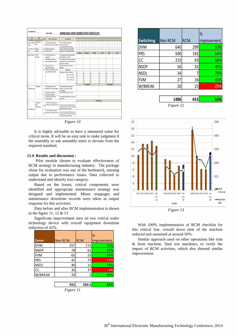
11.0 Results and discussion :
Pilot module chosen to evaluate effectiveness of
RCM strategy in manufacturing industry. The package
chose for evaluation was one of the bottleneck, missing
output due to performance issues. Data collected to
understand and identify loss category.
Based on the losses, critical components were
identified and appropriate maintenance strategy was
designed and implemented. Minor stoppages and
maintenance downtime records were taken as output
response for this activities.
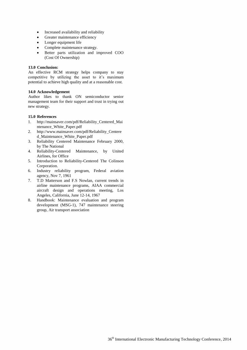
Data before and after RCM implementation is shown
in the figure 11, 12 & 13
Significant improvement seen on two critical wafer
technology device with overall equipment downtime
reduction of 42%.
Zener Non RCM RCM
%
improvement
DVM 257 113 56%
NSOP 78 61 22%
FVM 65 23 65%
PRS 42 72 -71%
NSOL 40 11 74%
CC 36 37 -3%
W/BREAK 33 5 86%
551 320.5 42% Figure 11
Switching Non RCM RCM
%
improvement
DVM 640 299 53%
PRS 500 182 64%
CC 210 93 56%
NSOP 56 31 45%
NSOL 34 7 79%
FVM 27 16 41%
W/BREAK 20 25 -25%
1486 653 56% Figure 12
Figure 13
With 100% implementation of RCM checklist for
this critical line, overall down time of the machine
reduced and sustained at around 50%.
Similar approach used on other operations like trim
& form machine, final test machines, to verify the
impact of RCM activities, which also showed similar
improvement.
Page 8
36th
International Electronic Manufacturing Technology Conference, 2014
Figure 14
RCM methodology helped to identify critical
components easily that causes failure. Every component
affecting a particular module / sub assembly is clearly
documented helps to identify critical components. This
methodology helped to identify all potential parts that
could cause potential failure to have an appropiate
maintenance strategy that helped to reduce machine
downtime significantly and effectively.
Figure 15
Figure 16
Summary and benefit of RCM
12.0 Summary :
However, total RCM concept is not just more than
just reducing downtime, but it focuses on process used to
determine what must be done to ensure that any physical
asset continues to do what its users wanted it to do in its
present operating context
RCM is a method which identifies applicable and
effective maintenance tasks needed to maintain the
inherent reliability of equipment at minimum cost.
RCM helps to clearly define the primary function
(the main reason why the asset exists). Once the primary
function established, asset modules and its functions
needs to be defined using a modular map with all the
sub-assemblies and components to clearly Identify
functional failure, failure modes and failure effects
(similar to FMEA concept) of each components. RPN
numbers assigned to each failure effect helps to prioritize
activities or actions needed for each failure mode. RCM
format also looks into the consequences of each failure
modes like, safety, impact to environment and will the
asset still be functional or non-functional. Each failure
modes are ranked based on the input from RPN and
consequences for further improvement.
Maintenance standards with proper frequency is
established to ensure that the asset perform it’s function
based on what the user intend to do.
With the implementation of RCM, once could expect
the following:
Greater safety and environmental integrity
Enhanced understanding of equipment
Page 9
36th
International Electronic Manufacturing Technology Conference, 2014
Increased availability and reliability
Greater maintenance efficiency
Longer equipment life
Complete maintenance strategy.
Better parts utilization and improved COO
(Cost Of Ownership)
13.0 Conclusion:
An effective RCM strategy helps company to stay
competitive by utilizing the asset to it’s maximum
potential to achieve high quality and at a reasonable cost.
14.0 Acknowledgement
Author likes to thank ON semiconductor senior
management team for their support and trust in trying out
new strategy.
15.0 References
1. http://mainsaver.com/pdf/Reliability_Centered_Mai
ntenance_White_Paper.pdf
2. http://www.mainsaver.com/pdf/Reliability_Centere
d_Maintenance_White_Paper.pdf
3. Reliability Centered Maintenance February 2000,
by The National
4. Reliability-Centered Maintenance, by United
Airlines, for Office
5. Introduction to Reliability-Centered The Colinson
Corporation.
6. Industry reliability program, Federal aviation
agency, Nov 7, 1961
7. T.D Matterson and F.S Nowlan, current trends in
airline maintenance programs, AIAA commercial
aircraft design and operations meeting, Los
Angeles, California, June 12-14, 1967
8. Handbook: Maintenance evaluation and program
development (MSG-1), 747 maintenance steering
group, Air transport association


![Color Panel Memory Test [CPMT]](https://static.documents.pub/doc/80x56/549ab475b4795938098b4593/color-panel-memory-test-cpmt.jpg)


