Page 1
*Corresponding Author Vol. 18 (No. 3) / 194
International Journal of Thermodynamics (IJoT) Vol. 18 (No. 3), pp. 194-198, 2015 ISSN 1301-9724 / e-ISSN 2146-1511 doi: 10.5541/ijot.5000083205 www.ijoticat.com Published online: September 1, 2015
Effects of Operating Pressure on Energy-saving of Water Recycling Utilization
with MVR system in Oil Extraction Fields
Li Liansheng*, Zhao Yuanyang, Wang Le, Xiao Jun, Yang Qichao, Liu Guangbin, Tang Bin
State Key Laboratory of Compressor Technology, Hefei General Machinery Research Institute, Hefei 230031, P. R. China
E-mail: [email protected]
Received 24 December 2014, Accepted 24 July 2015
Abstract
One of the most effective methods for the extraction of crude oil with high viscosity is injecting high temperature
water vapor to the oil well. To save water consumption and achieve zero discharge, it is needed to separate and purify
the water, which is mixed with oil, mud and other impurities. In this paper, the mechanical vapor recompression (MVR)
system is analyzed and the parameters for analysis are based on a demonstration project on water recycling utilization
in the Karamay crude oil field in northwest China. Two kinds of technological processes, high pressure and low
pressure processes are proposed by the authors. The recovery work is utilized to decrease power consumption of the
compression work and the energy from the high temperature purified water is used to drive an absorption refrigerator.
The results show that 680 kJ/kg of energy can be saved in the high pressure process compared to a low-pressure
process. For low pressure process, the saving energy is only 420 kJ/kg, the material is easily corrosive, and additional
9.8t/h cooling water is needed. Compared the MVR system with TVR one, when the same pressure ratio and mass
quantity of condensing water are obtained, the MVR system need use about 80 kW electrical power from compressor
and the TVR system need use 3129.5 kW thermal energy from steam.
Keywords: Water recycling utilization; MVR; energy-saving analysis.
1. Introduction
Since the 1950s, the petroleum and natural gas have been
becoming the main primary energy sources. And this
dominance is expected to continue for several more decades
[1]. Despite the growth in low-carbon sources of energy, the
fossil fuels still remain dominant in the global energy market
[2]. In the developing countries such as China, India and the
Middle East, the petroleum and natural gas still take the key
roles in the development of economy and society.
There are two problems during the extraction process of
crude oil. One is that oil well becomes much deeper and the
viscosity of crude oil is becoming much greater, so its
extraction becomes very difficult. The other is that the crude
oil extraction will consume much more resources such as
energy and water, which results in serious environmental
pollution [3].
To extract more crude oil or increase the efficiency of
extraction, some methods and technologies are applied [4],
[5]. For example, the artificial pressure lifts by pump,
compressor or other lifting are used as conventional methods.
To maintain pressure in the well, it is required to inject gas
or liquid into well. To lower the viscosity of crude oil and
increase its flow ability, the chemical or thermal techniques
are used. Whatever method or technique is taken, the
additional energy consumption will need. So, the most
important thing is how to decrease additional consumption
of energy.
The energy and exergy analyses of the oil and gas plant
were conducted by some researchers. Oliveira and Van
Hombeeck [6] conducted an exergy analysis of a Brazilian
oil platform and found that the least exergy-efficient
subsystem was the oil and gas separation, while the most
exergy-consuming ones were the petroleum heating and the
gas compression processes. Voldsund [7]-[8] carried out an
exergy analysis of a Norwegian oil platform and showed that
the greatest thermodynamic irreversibility was associated
with processes where large changes in pressure took place.
Nguyen [9]-[10] conducted a generic analysis of Norwegian
oil and gas facilities as well as a mature field. They suggested
that the most exergy-destruction generally exists in the
production manifold and gas compression trains, which was
particularly sensitive to the compressor and pump
efficiencies, as well as to the petroleum composition. It was
also shown that the separation work performed on the mature
field is greater than in similar facilities because of higher
propane and water fractions of the well-streams.
In the process of crude oil extraction, the environmental
pollution is another big issue [11]. For the extraction of high-
viscosity crude oil, it is necessary to inject water vapor with
high pressure and temperature into the well. But if the water
is not in cyclic utilization, not only a lot of water resource is
wasted, but also the environment around the well is polluted
owing to the direct discharge of the water separated from the
mixture, as shown in Figure 1.
Page 2
195 / Vol. 18 (No. 3) Int. Centre for Applied Thermodynamics (ICAT)
High temperature vapor (boiler)
Injecting underground
Mixture extraction (oil and water, etc.)
Discharge (High temperature water)
Separation (Sulfur, etc.)
Crude Oil
Figure 1. Traditional flow chart of oil extraction with vapor
injecting.
To save energy and protect the environment, the water
has to be utilized circularly in the extraction process of crude
oil, and the schematic diagram is shown in Figure 2. Water
from underground or other resources is pumped to boiler
where the water is heated and becomes vapor with high
temperature and pressure, and then vapor is injected into the
oil well, in which oil with higher viscosity is diluted by the
vapor [12]. Then the mixture of crude oil and vapor is
extracted up to the ground and flows into the separator,
where the mud, sulfur, CO2, water and so on are separated.
The crude oil from the separator will be transported to the
refinery.
Figure 2. Schematic diagram of water cyclic utilization.
To get purified water for cyclic utilization, the water from
separator must be desalted. The desalination process needs
energy, and the quality of energy is related to the properties
of salt water and the working condition of process system.
There are two basic methods to provide energy to
evaporators, which are the thermal vapor recompression
(TVR) and the mechanical vapor recompression (MVR) [6].
For an evaporator with MVR, the vapor leaving an
evaporation stage is compressed to raise its saturation
pressure and temperature. Then the compressed vapor can be
used as heating steam in the same stage, and the main extra
energy provided for evaporation is the mechanical work from
compressor.
For TVR system, the vapor leaving the evaporator is
compressed in the ejector by other steam (motive steam) with
higher temperature and pressure. Hence the vapor can be
reused as the heating steam. Here the input energy to the
evaporator is from the motive steam.
The MVR systems became especially popular in the late
1970's to early 1980's. And it was used in the fields of
chemical engineering, food processing, papermaking, and
pharmacy processing, etc. [6-8]. In recent years, the new
technologies of MVR were further investigated, and it was
applied in some new fields such as materials, solar and so on
[9-12].
In this paper, the energy saving analysis is done on water
recycling utilization with MVR system in the field of crude
oil extraction. The parameters for energy saving analysis are
from a demonstration project in the Karamay crude oil field
in northwest China. Two technical processes in MVR system
are proposed, and the MVR and TVR are compared.
2. Basic Principle of Water Recycling Utilization with
MVR in Oil Extraction Field
The Karamay crude oil field attached to China National
Petroleum Corporation (CNPC), located at Northwest of
China, is now extracting the crude oil with high viscosity by
injecting the vapor at high temperature and pressure. The
mixture flowing out from oil well is separated into crude oil,
water, and other impurities, such as sulfur and CO2. There
still exist grease dirty, salt and suspended solids in the water.
The main focus of the research is on the water treatment.
Hence, the main parameters of water are expressed in Table
1.
Table 1. Main Parameters of Water.
Parameter Value
Flow rate of water 10 t/h
Pressure of water 0.618 MPa
Temperature of water 160 °C
Degree of dryness Saturate water
Impurity in water Grease dirty, salt, suspended solids
So far, in the process of extracting oil, the water separated
from the mixture is directly discharged to the surroundings,
which results in the environmental pollution and energy
waste. To improve this situation, the water should be used
circularly. Firstly, the grease dirty and suspended solids are
divided from the water. Secondly, the salt is separated by
evaporator with MVR. And finally, the purified water is
pumped to the boiler. Thus the water cyclic utilization is
realized.
Two basic technological processes, which are high
pressure and low pressure processes, are proposed by the
authors. The detailed explanation and analysis of these two
processes are shown as below.
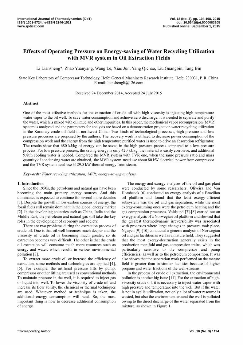
2.1 Technological Process in Low Pressure
The technological process of water cyclic utilization and
its purification in low pressure process is shown in Figure
3.The mixture leaving the oil well is separated into crude oil,
high temperature sewage with little grease, sludge, and other
impurities.
The high temperature sewage of 10t/h at the state of
160 °C and 0.6MPa flows into the degreaser firstly, where
the grease and sludge are removed and at the outlet of
degreaser water with salt is almost kept in the original flow
rate, temperature and pressure. Then the water with salt
enters the expander (process 0-1). The outputs of expander
of 65% efficiency are 32 kW. This power can be used to run
the compressor in the MVR system. The state of water is
100°C, 0.1MPa and dryness of 0.11 at the outlet of expander
(point 1’). Then the water goes into the vapor-liquid
separator, where 1.1t/h saturation vapor (100 °C, 0.1MPa)
flows into absorption refrigerator (point 2), and becomes the
liquid water. And then the water is directly pumped to the
boiler for recycling.
Water supply Boiler Water purifier
Purified water
Separator
Wipe-off salt
Wipe-off mercury, CO2, etc
Oil well Crude oil
Steam (high pressure
& temperature
Page 3
Int. J. of Thermodynamics (IJoT) Vol. 18 (No. 3) / 196
(strong brine)
High temperature sewage
160℃, 0.6MPa,10t/h
100℃, 0.1MPa
x=0.11
100℃,0.1MPa,1.1t/h
(saturated vapor)
Degreaser
ExpanderCompressorMotor
Oil
Sludge160℃, 0.6MPa,10t/h
<300mg/L(Oil)
<100mg/L
(Suspended solids)32kW
Valve
Gas-
liq
uid
sep
ara
tor
100℃, 0.1MPa
8.9 t/h(Water)
Pump
Cold water,7℃
Absorption
refrigerator
Emptying pump
Non-condensable
gas discharge
Boiler
Circulating
pump
100℃, 0.1MPa, 1.0 t/h
0.107MPa,105℃,7.9t/h
(Superheated vapor)
0.107MPa,105℃,7.9 t/h
(saturated water)
80℃, 0.1MPa, 1.1t/h
(Water)
80℃,0.107MPa,
1.1 t/h(water)
80kW
Pu
rifi
e
r
Valve
(saturated vapor)
Line Color
Sewage
Salty water
Pure water
Vapor0
1'
2
5
2
3
4
Figure 3. Water purification chart in low pressure process.
In the absorption refrigerator, the saturated vapor is
condensed and releases the condensation heat for driving
refrigerator. At the same time, the 7°C cold water can be
gotten to be used for air conditioning of the working and
living environment in extracting oil field.
The saturated water (100°C, 0.1 MPa) of 8.9t/h flowed
from vapor-liquid separator is pumped into the water purified
system and evaporator for desalination. In the evaporator, the
energy desired for desalination comes from vapor itself, i.e.,
the saturated vapor from the evaporator is compressed to a
new state (105°C, 0.107 MPa) so that a temperature
difference of 5 °C or above 5 °C is obtained, which can be
used as the heat transfer power in evaporation process. The
purified saturate water (105°C, 0.107 MPa) of about 7.9t/h
from evaporator flows into the boiler for reuse. The total
amount of purified water reaches 9 t/h.
For low pressure process, the salinity of water will
increase when it flow out from the expander because there is
some vapor produced during the expansion process. The 11%
of the sewage is changed from water to saturation vapor. At
this expansion process, all the salts are kept in the water.
Hence the salinity of water which flow to the evaporator is
higher than the original one of sewage.
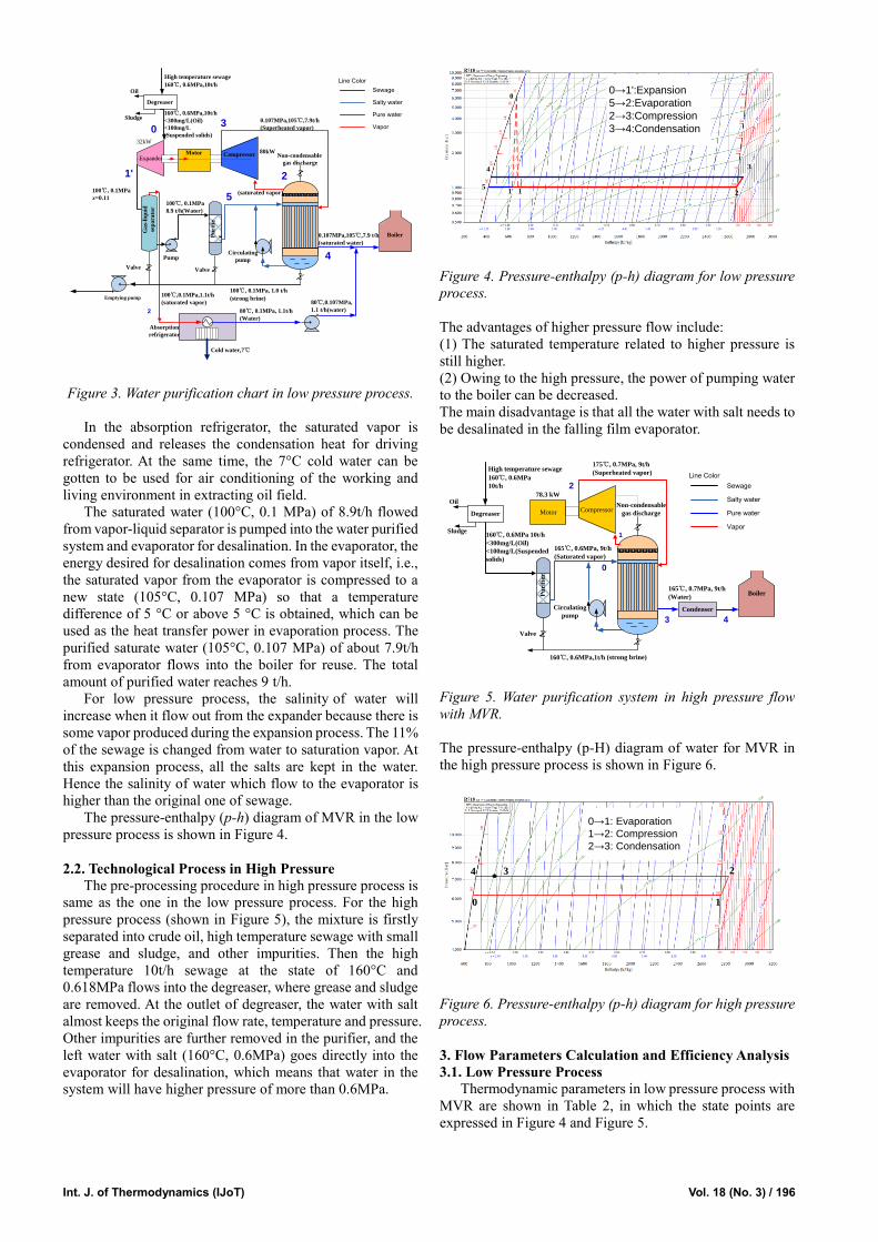
The pressure-enthalpy (p-h) diagram of MVR in the low
pressure process is shown in Figure 4.
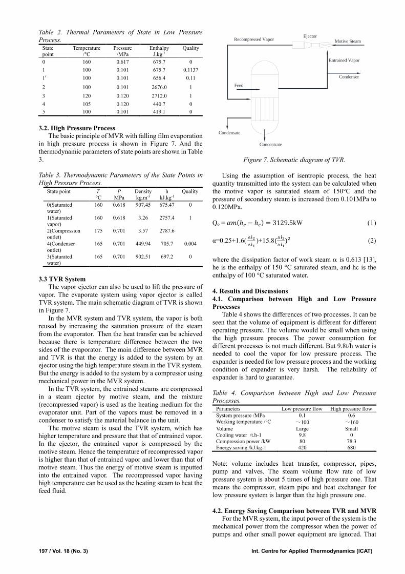
2.2. Technological Process in High Pressure
The pre-processing procedure in high pressure process is
same as the one in the low pressure process. For the high
pressure process (shown in Figure 5), the mixture is firstly
separated into crude oil, high temperature sewage with small
grease and sludge, and other impurities. Then the high
temperature 10t/h sewage at the state of 160°C and
0.618MPa flows into the degreaser, where grease and sludge
are removed. At the outlet of degreaser, the water with salt
almost keeps the original flow rate, temperature and pressure.
Other impurities are further removed in the purifier, and the
left water with salt (160°C, 0.6MPa) goes directly into the
evaporator for desalination, which means that water in the
system will have higher pressure of more than 0.6MPa.
0
1 2
34
5
0→1':Expansion
5→2:Evaporation
2→3:Compression
3→4:Condensation
1'
Figure 4. Pressure-enthalpy (p-h) diagram for low pressure
process.
The advantages of higher pressure flow include:
(1) The saturated temperature related to higher pressure is
still higher.
(2) Owing to the high pressure, the power of pumping water
to the boiler can be decreased.
The main disadvantage is that all the water with salt needs to
be desalinated in the falling film evaporator.
High temperature sewage
160℃, 0.6MPa
10t/h
DegreaserCompressorMotor
78.3 kW
Valve
Boiler
Condenser
175℃, 0.7MPa, 9t/h
(Superheated vapor)
160℃, 0.6MPa,1t/h
165℃, 0.7MPa, 9t/h
(Water)
Oil
Sludge160℃, 0.6MPa 10t/h
<300mg/L(Oil)
<100mg/L(Suspended
solids)
Pu
rifi
er
Circulating
pump
(strong brine)
Non-condensable
gas discharge
165℃, 0.6MPa, 9t/h
(Saturated vapor)
Line Color
Sewage
Salty water
Pure water
Vapor
0
1
2
3 4
Figure 5. Water purification system in high pressure flow
with MVR.
The pressure-enthalpy (p-H) diagram of water for MVR in
the high pressure process is shown in Figure 6.
0 1
24
0→1: Evaporation
1→2: Compression
2→3: Condensation
3
Figure 6. Pressure-enthalpy (p-h) diagram for high pressure
process.
3. Flow Parameters Calculation and Efficiency Analysis
3.1. Low Pressure Process
Thermodynamic parameters in low pressure process with
MVR are shown in Table 2, in which the state points are
expressed in Figure 4 and Figure 5.
Page 4
197 / Vol. 18 (No. 3) Int. Centre for Applied Thermodynamics (ICAT)
Table 2. Thermal Parameters of State in Low Pressure
Process. State point
Temperature /°C
Pressure /MPa
Enthalpy J.kg-1
Quality
0 160 0.617 675.7 0
1 100 0.101 675.7 0.1137
1′ 100 0.101 656.4 0.11
2 100 0.101 2676.0 1
3 120 0.120 2712.0 1
4 105 0.120 440.7 0
5 100 0.101 419.1 0
3.2. High Pressure Process
The basic principle of MVR with falling film evaporation
in high pressure process is shown in Figure 7. And the
thermodynamic parameters of state points are shown in Table
3.
Table 3. Thermodynamic Parameters of the State Points in
High Pressure Process.
State point T
°C
P
MPa
Density
kg.m-3
h
kJ.kg-1
Quality
0(Saturated
water)
160 0.618 907.45 675.47 0
1(Saturated
vapor)
160 0.618 3.26 2757.4 1
2(Compression outlet)
175 0.701 3.57 2787.6
4(Condenser
outlet)
165 0.701 449.94 705.7 0.004
3(Saturated
water)
165 0.701 902.51 697.2 0
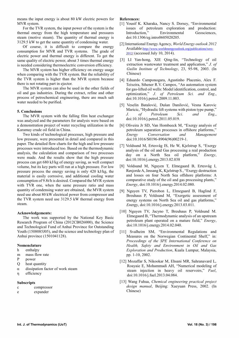
3.3 TVR System
The vapor ejector can also be used to lift the pressure of
vapor. The evaporate system using vapor ejector is called
TVR system. The main schematic diagram of TVR is shown
in Figure 7.
In the MVR system and TVR system, the vapor is both
reused by increasing the saturation pressure of the steam
from the evaporator. Then the heat transfer can be achieved
because there is temperature difference between the two
sides of the evaporator. The main difference between MVR
and TVR is that the energy is added to the system by an
ejector using the high temperature steam in the TVR system.
But the energy is added to the system by a compressor using
mechanical power in the MVR system.
In the TVR system, the entrained steams are compressed
in a steam ejector by motive steam, and the mixture
(recompressed vapor) is used as the heating medium for the
evaporator unit. Part of the vapors must be removed in a
condenser to satisfy the material balance in the unit.
The motive steam is used the TVR system, which has
higher temperature and pressure that that of entrained vapor.
In the ejector, the entrained vapor is compressed by the
motive steam. Hence the temperature of recompressed vapor
is higher than that of entrained vapor and lower than that of
motive steam. Thus the energy of motive steam is inputted
into the entrained vapor. The recompressed vapor having
high temperature can be used as the heating steam to heat the
feed fluid.
Figure 7. Schematic diagram of TVR.
Using the assumption of isentropic process, the heat
quantity transmitted into the system can be calculated when
the motive vapor is saturated steam of 150°C and the
pressure of secondary steam is increased from 0.101MPa to
0.120MPa.
Qo = 𝛼𝑚(ℎ𝑒 − ℎ𝑐) = 3129.5kW (1)
α=0.25+1.6(△i2
△i1)+15.8(
△i2
△i1)2 (2)
where the dissipation factor of work steam is 0.613 [13],
he is the enthalpy of 150 °C saturated steam, and hc is the
enthalpy of 100 °C saturated water.
4. Results and Discussions
4.1. Comparison between High and Low Pressure
Processes
Table 4 shows the differences of two processes. It can be
seen that the volume of equipment is different for different
operating pressure. The volume would be small when using
the high pressure process. The power consumption for
different processes is not much different. But 9.8t/h water is
needed to cool the vapor for low pressure process. The
expander is needed for low pressure process and the working
condition of expander is very harsh. The reliability of
expander is hard to guarantee.
Table 4. Comparison between High and Low Pressure
Processes. Parameters Low pressure flow High pressure flow
System pressure /MPa 0.1 0.6
Working temperature /°C ~100 ~160
Volume Large Small Cooling water /t.h-1 9.8 0
Compression power /kW 80 78.3
Energy saving /kJ.kg-1 420 680
Note: volume includes heat transfer, compressor, pipes,
pump and valves. The steam volume flow rate of low
pressure system is about 5 times of high pressure one. That
means the compressor, steam pipe and heat exchanger for
low pressure system is larger than the high pressure one.
4.2. Energy Saving Comparison between TVR and MVR
For the MVR system, the input power of the system is the
mechanical power from the compressor when the power of
pumps and other small power equipment are ignored. That
Entrained Vapor
Condenser
Feed
Ejector
Concentrate
Recompressed Vapor
Condensate
Motive Steam
Page 5
Int. J. of Thermodynamics (IJoT) Vol. 18 (No. 3) / 198
means the input energy is about 80 kW electric powers for
MVR system.
For the TVR system, the input power of the system is the
thermal energy from the high temperature and pressures
steam (motive steam). The quantity of thermal energy is
3129.5 kW to get the same quantity of condensing water.
Of course, it is difficult to compare the energy
consumption for MVR and TVR systems. The grade of
electric power and thermal energy is different. To get the
same quality of electric power, about 3 times thermal energy
is needed considering thermoelectric conversion efficiency.
The MVR system has higher efficiency on energy usage
when comparing with the TVR system. But the reliability of
the TVR system is higher than the MVR system because
there is not rotating part in ejector.
The MVR system can also be used in the other fields of
oil and gas industries. During the extract, refine and other
process of petrochemical engineering, there are much salt
water needed to be purified.
5. Conclusions
The MVR system with the falling film heat exchanger
was analyzed and the parameters for analysis were based on
a demonstration project of water recycling utilization in the
Karamay crude oil field in China.
Two kinds of technological processes, high pressure and
low pressure, were presented in detail and compared in this
paper. The detailed flow charts for the high and low pressure
processes were introduced too. Based on the thermodynamic
analysis, the calculation and comparison of two processes
were made. And the results show that the high pressure
process can get 680 kJ/kg of energy saving, as well compact
volume, but its key parts will run at a high pressure. For low
pressure process the energy saving is only 420 kJ/kg, the
material is easily corrosive, and additional cooling water
consumption of 9.8t/h is desired. Compared the MVR system
with TVR one, when the same pressure ratio and mass
quantity of condensing water are obtained, the MVR system
need use about 80 kW electrical power from compressor and
the TVR system need use 3129.5 kW thermal energy from
steam.
Acknowledgements:
The work was supported by the National Key Basic
Research Program of China (2012CB026000), the Science
and Technological Fund of Anhui Province for Outstanding
Youth (1508085J05), and the science and technology plan of
Anhui province (1501041128).
Nomenclature
h enthalpy
m mass flow rate
P power
Q heat quantity
dissipation factor of work steam
η efficiency
Subscripts
c compressor
e expander
References:
[1] Yousif K. Kharaka, Nancy S. Dorsey, “Environmental
issues of petroleum exploration and production:
Introduction,” Environmental Geosciences,
doi:10.1306/eg.intro0605020205.
[2] International Energy Agency, World Energy outlook 2012
Available:http://www.worldenergyoutlook.org/publications/weo-
2012/ (accessed July 10, 2014).
[3] LI Yan-hong, XIE Qing-lin, “Technology of oil
extraction wastewater treatment and application,” J. of
Guilin Institute of Technology, 23, 95-98, 2003. (In
Chinese)
[4] Eduardo Camponogara, Agustinho Plucenio, Alex F.
Teixeira, Sthener R.V. Campos, “An automation system
for gas-lifted oil wells: Model identification, control, and
optimization,” J. of Petroleum Sci. and Eng.,
doi:10.1016/j.petrol.2009.11.003.
[5] Veselin Batalović, Dušan Danilović, Vesna Karovic
Maricic, “Hydraulic lift systems with piston type pump,”
J. of Petroleum Sci. and Eng.,
doi:10.1016/j.petrol.2011.05.019.
[6] Oliveira Jr SD, Van Hombeeck M, “Exergy analysis of
petroleum separation processes in offshore platforms,”
Energy Conversation and Management
doi:10.1016/S0196-8904(96)00219-1.
[7] Voldsund M, Ertesvåg IS, He W, Kjelstrup S, “Exergy
analysis of the oil and Gas processing a real production
day on a North Sea oil platform,” Energy,
doi:10.1016/j.energy.2013.02.038
[8] Voldsund M, Nguyen T, Elmegaard B, Ertesvåg I,
Røsjorde A, Jøssang K, Kjelstrup S., “Exergy destruction
and losses on four North Sea offshore platforms: A
comparative study of the oil and gas processing plants,”
Energy, doi:10.1016/j.energy.2014.02.080.
[9] Nguyen TV, Pierobon L, Elmegaard B, Haglind F,
Breuhaus P, Voldsund M, “Exergetic assessment of
energy systems on North Sea oil and gas platforms,”
Energy, doi:10.1016/j.energy.2013.03.011.
[10] Nguyen TV, Jacyno T, Breuhaus P, Voldsund M.
Elmegaard B, “Thermodynamic analysis of an upstream
petroleum plant operated on a mature field,” Energy,
doi:10.1016/j.energy.2014.02.040.
[11] Svalheim SM, “Environmental Regulations and
Measures on the Norwegian Continental Shelf,” in:
Proceedings of the SPE International Conference on
Health, Safety and Environment in Oil and Gas
Exploration and Production, Kuala Lumpur, Malaysia,
pp. 1-10, 2002.
[12] Mozaffar S, Nikookar M, Ehsani MR, Sahranavard L,
Roayaie E, Mohammadi AH, “Numerical modeling of
steam injection in heavy oil reservoirs,” Fuel,
doi:10.1016/j.fuel.2013.04.084.
[13] Wang Fuhua, Chemical engineering practical project
design manual, Beijing: Xueyuan Press, 2002. (In
Chinese)