First published: 2007 Güntner AG & Co. KG Hans-Güntner-Straße 2 - 6 82256 Fürstenfeldbruck GERMANY Technical article Energy saving on the low-pressure side of a refrigerating plant Main topics: Saving energy– what for? Reduction of CO 2 emission Reduction of operating costs Carnot efficiency, process efficiency and COP Influence of condensing and evaporating temperature on the COP Influence of superheating and subcooling Investment costs vs. operating costs Investment costs depending on the driving temperature difference. Operating costs for compressors, fans and electric defrost heating Does the use of a larger evaporator make sense? Evaporator designs What are the effects of air rectifiers and defrost socks on the energy consumption? Technical feasibility How can small temperature differences be realised without large efforts in control? Dr. Franz Summerer, Dipl.-Phys. Head of R&D
Transcript
First published: 2007
Güntner AG & Co. KG Hans-Güntner-Straße 2 - 6 82256 Fürstenfeldbruck GERMANY
Technical article
Energy saving on the low-pressure side of a refrigerating plant
Main topics:
Saving energy– what for?
Reduction of CO2 emission Reduction of operating costs
Carnot efficiency, process efficiency and COP Influence of condensing and evaporating temperature on the COP Influence of superheating and subcooling
Investment costs vs. operating costs Investment costs depending on the driving temperature difference. Operating costs for compressors, fans and electric defrost heating Does the use of a larger evaporator make sense?
Evaporator designs What are the effects of air rectifiers and defrost socks on the energy consumption?
Technical feasibility How can small temperature differences be realised without large efforts in control?
Dr. Franz Summerer, Dipl.-Phys.
Head of R&D
Güntner Technical Article: Energy saving on the low-pressure side of a refrigerating plant
The German government wants CO2 emissions to be reduced by 20 to 30% by 2020. It is obvious that this will not be possible simply by extending the use of alternative energies. Energy saving will be a very significant part of this ambitious plan. In Germany, refrigeration engineering is responsible for about 6% of the total consumption of primary energy, and consequently, also about 6% of CO2 emissions; a large part of this energy is used to cool food
.
Figure 1: Energy distribution for generating refrigeration in Germany
Nahrungsmittel Food
Industrie Industry
Klimatisierung Air conditioning
Sonstige Other
If we consider that cooling food and air conditioning in buildings are both strong growth areas, it becomes obvious that the Germany government's very ambitious plans pose enormous challenges for refrigeration engineering. 30% energy saved by 2020 is then a minimum goal.
Energy saving for the environment may well be an honourable objective. But in the final analysis, companies have to make a profit and energy saving measures must somehow pay for themselves. Many people argue that the expected energy price increases alone justify any investment that reduces energy consumption. But the truth is rather more sobering. If you adjust the energy price increases of the last 30 years with the rate of inflation, you see that energy prices have remained almost constant (see Figure 2)
66.9%9.0%
21.9% 2.2% Nahrungsmittel
Industrie
Klimatisierung
Sonstige
(see Figure 1)
Güntner Technical Article: Energy saving on the low-pressure side of a refrigerating plant
Figure 2: Energy price developments in Germany adjusted for inflation
Inflationsbereinigte Energiepreise in Deutschland im Vergleich
Energy price developments in Germany adjusted for inflation in comparison
Preis in Cent/kWh Price in cents/kWh
Strom/Gas/Öl Electricity/Gas/Oil
Datenquelle: Bundesministerium für Wirtschaft und Arbeit, 2006; Mineralölwirtschaftsverband, 2004;
Tecson-Digital, 2005
Data source: German Federal Ministry for Economics and Labour, 2006; Association of the German
Petroleum Industry, 2004; Tecson-Digital, 2005
Since the energy market is now globalised, we should not expect to see any major deviation from this development. Therefore, if you intend spending money on reducing the energy and operating costs of a refrigeration system, you must examine very closely where this money should best be invested. After all, there are very many impractical places where you can, admittedly, save energy but will never be able to amortise the costs over the lifetime of the system. However, there are also many sensible approaches where money invested can be amortised within just a few years. Some of these sensible approaches are described in brief below.
2. Carnot efficiency, quality grade and COP of refrigeration systems
Most refrigeration units these days work according to the vapour compression process. The vapour compression process is also known as a reverse Carnot process. The maximum possible efficiency of such a process is defined by the first and second laws of thermodynamics in relation to the two temperature levels: condensation temperature and evaporation temperature.
For refrigeration units we usually don't use the term efficiency, but coefficient of performance (COP). Consequently, the maximum COP of a refrigeration unit is:
01
0
TT
TCarnot
where T0 is the evaporation temperature and T1 is the condensation temperature – both as absolute temperatures in K.
Güntner Technical Article: Energy saving on the low-pressure side of a refrigerating plant
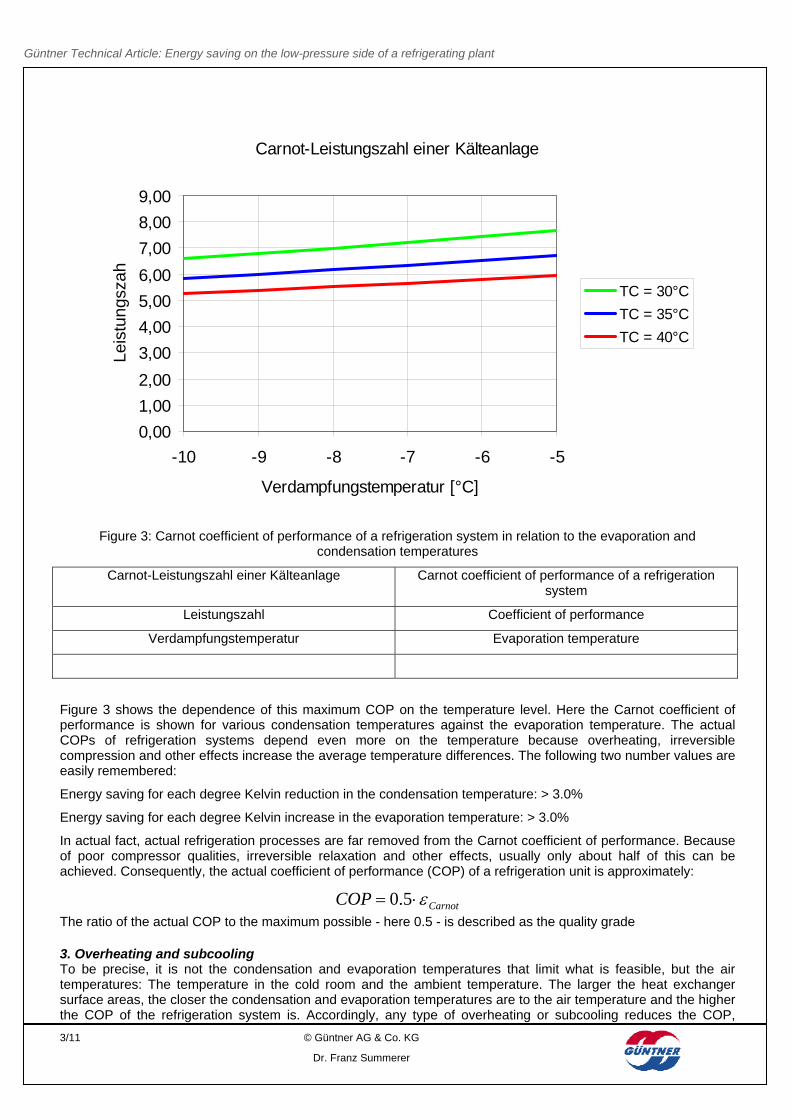
Figure 3: Carnot coefficient of performance of a refrigeration system in relation to the evaporation and condensation temperatures
Carnot-Leistungszahl einer Kälteanlage Carnot coefficient of performance of a refrigeration system
Leistungszahl Coefficient of performance
Verdampfungstemperatur Evaporation temperature
Figure 3 shows the dependence of this maximum COP on the temperature level. Here the Carnot coefficient of performance is shown for various condensation temperatures against the evaporation temperature. The actual COPs of refrigeration systems depend even more on the temperature because overheating, irreversible compression and other effects increase the average temperature differences. The following two number values are easily remembered:
Energy saving for each degree Kelvin reduction in the condensation temperature: > 3.0%
Energy saving for each degree Kelvin increase in the evaporation temperature: > 3.0%
In actual fact, actual refrigeration processes are far removed from the Carnot coefficient of performance. Because of poor compressor qualities, irreversible relaxation and other effects, usually only about half of this can be achieved. Consequently, the actual coefficient of performance (COP) of a refrigeration unit is approximately:
CarnotCOP 5.0
The ratio of the actual COP to the maximum possible - here 0.5 - is described as the quality grade 3. Overheating and subcooling To be precise, it is not the condensation and evaporation temperatures that limit what is feasible, but the air temperatures: The temperature in the cold room and the ambient temperature. The larger the heat exchanger surface areas, the closer the condensation and evaporation temperatures are to the air temperature and the higher the COP of the refrigeration system is. Accordingly, any type of overheating or subcooling reduces the COP,
Güntner Technical Article: Energy saving on the low-pressure side of a refrigerating plant
because this causes a situation where the condensation temperature is higher than necessary or the evaporation temperature is lower than required.
Log
p
h
60°C
50°C
40°CEnthitzungEnthitzungUnterkUnterk..
Überh.Überh.
COP!COP!
Log
p
h
60°C
50°C
40°CEnthitzungEnthitzungUnterkUnterk..
Überh.Überh.
COP!COP!
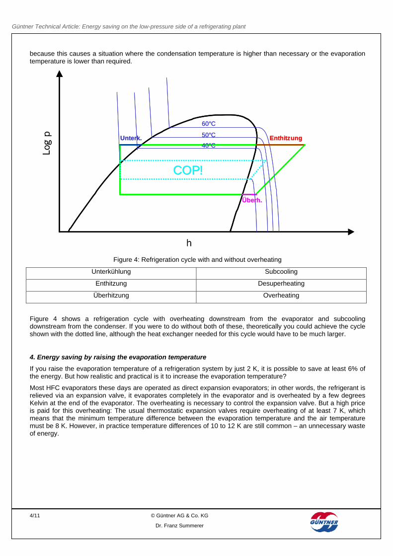
Figure 4: Refrigeration cycle with and without overheating
Unterkühlung Subcooling
Enthitzung Desuperheating
Überhitzung Overheating
Figure 4 shows a refrigeration cycle with overheating downstream from the evaporator and subcooling downstream from the condenser. If you were to do without both of these, theoretically you could achieve the cycle shown with the dotted line, although the heat exchanger needed for this cycle would have to be much larger.
4. Energy saving by raising the evaporation temperature
If you raise the evaporation temperature of a refrigeration system by just 2 K, it is possible to save at least 6% of the energy. But how realistic and practical is it to increase the evaporation temperature?
Most HFC evaporators these days are operated as direct expansion evaporators; in other words, the refrigerant is relieved via an expansion valve, it evaporates completely in the evaporator and is overheated by a few degrees Kelvin at the end of the evaporator. The overheating is necessary to control the expansion valve. But a high price is paid for this overheating: The usual thermostatic expansion valves require overheating of at least 7 K, which means that the minimum temperature difference between the evaporation temperature and the air temperature must be 8 K. However, in practice temperature differences of 10 to 12 K are still common – an unnecessary waste of energy.
Güntner Technical Article: Energy saving on the low-pressure side of a refrigerating plant
Figure 5: Investment costs for evaporators in relation to the evaporation temperature
Mittleres Preis-Leistungs-Verhältnis Verdampfer Average price-performance ratio of evaporators
Verdampfungstemperatur Evaporation temperature
Naturally, a smaller temperature difference requires a larger, and consequently, more expensive evaporator. Figure 5 shows the investment costs for an evaporator with an air inlet temperature of 0°C. As an approximation you can say that when the temperature difference is halved, the costs almost double, although the cost increase is not linear but slightly exponential.
On the basis of these investment costs and based on the above-mentioned energy saving per degree Kelvin you could calculate the time that it would take for the added costs for a larger evaporator to be amortised. But if you simply choose an evaporator that provides the same output with a smaller temperature difference, this does not automatically save energy. This is because larger evaporators generally don't simply have a larger surface area, they also have a more powerful fan because they are usually used for greater capacities. But if you reduce the temperature difference, this higher air capacity is not required. That means: with a lower temperature difference you can save energy only if the evaporator has been optimised to take account of this.
The table below shows three possible evaporators, all of which produce 10 kW output at an air inlet temperature of 0°C but at different evaporation temperatures:
Evaporator type Power T0 COP Electricity consumption
Table 1: Comparison of various evaporator types at 0°C air temperature
If you assume an annual operation time of approx. 5,000 hours with a COP of 3.0 at –10°C, the evaporator needs approx. 16,667 kWh per year. This slightly larger evaporator 2 allows an evaporation temperature of –8.5°C and thus saves about 4.5% evaporator energy. It uses the same fan with 0.48 kW electric power, which means that in total it saves about 700 kWh per year. For an additional price of just EUR 74 and at an electricity price of 10 cents/kWh, this investment would pay for itself after about one year.
However, if you mean especially well and choose the even larger evaporator that allows an evaporation temperature of – 8°C, unfortunately you achieve exactly the opposite: The larger evaporator has a more powerful fan with a power input of 0.75 kW and thus consumes a lot more energy for the fan. Unfortunately, in this case the additional investment leads to additional consumption. If you also consider the additional refrigeration capacity for the heat from the fan, the comparison is even more negative.
This comparison looks slightly different if you assume lower temperatures. For example, if you choose an air temperature of –20°C and an evaporation temperature of –30°C, the COP falls to approx. 1.9. In this case, the energy needed to drive the compressor plays a more important role, which by implication, means that the energy needed to drive the fan plays less of a role.
But the situation changes entirely if the electric defrost heating is also considered. An evaporator that is operated with a smaller temperature difference does not ice up as much and must therefore be defrosted less frequently. Electric defrosting uses direct energy and also indirect energy because it has to be cooled again via the refrigeration system. If the evaporator types 1 and 3 from Table 1 are compared, it can be seen that evaporator type 1 ices up much faster than evaporator type 3. On the one hand, this is because of the bigger temperature difference of evaporator type 1, and on the other hand, due to the smaller surface area of the heat exchanger.
After about 5 hours, evaporator type 1 has about 1mm of ice, which weighs about 17kg. After roughly 8 hours, evaporator type 2 has accumulated about 1mm of ice, weighing 29 kg. The annual defrosting energy, including the additional refrigeration requirements, is 7,070 kWh for evaporator type 1 but only 5,876 kWh for evaporator type 3. Table 2 shows the energy consumption of the 3 evaporator types taking the defrosting power into consideration.
Evaporator type Power T0 COP Electricity consumption
Table 2: Comparison of various evaporator types with consideration of defrosting
While evaporator type 2 is still the most economical, evaporator type 3 also saves about 788 kWh electricity compared to variant 1 and would pay for itself after about 2 years with an electricity price of 10 cents.
5. Evaporator add-ons
In many cases additional equipment is attached to evaporators; for example, to steer the air in the required direction or to close the evaporator during defrosting to reduce defrosting energy. Unfortunately, it is often forgotten that devices such as this cause a pressure loss, which leads to increased energy consumption. Two typical examples of the effects of this are described below.
5.1 Air rectifiers
To take the cold air that is blown out as far away as possible from the air cooler, the air flow can be bundled with the help of air rectifiers. Air rectifier grids are widely used – a honeycomb-shaped or rectangular grid that removes the radial parts of the airflow velocity and directs the air flow forward (see Figure 6).
However, these grids cause an additional pressure loss that the fan has to overcome. This reduces the air volume by about 10% on average – depending on the fan and the diameter. This reduced air volume, in turn, reduces the
Güntner Technical Article: Energy saving on the low-pressure side of a refrigerating plant
evaporator capacity, which results either in longer running times for the compressor or a lower evaporation temperature. The evaporator's energy consumption increases by about 1%.
On the other hand, a guide wheel, such as the Günter Streamer, bundles the air flow with no additional pressure loss and, consequently, no additional energy consumption. It is also less expensive and is easy to retrofit (see Figure 7).
Figure 6: Air rectifier grid Figure 7: Güntner Streamer
5.2 Defrost sock
Usually, during defrosting a large part of the defrosting energy flows from the air cooler into the cold room. On the one hand, with electric defrosting this heat must be provided directly and on the other hand, with every type of defrosting, it has to be cooled away again after defrosting. To reduce this heat loss during defrosting, defrost sock are placed on the fans. Airbags that are inflated while the fans are running and that deflate and form a seal when the fan is not operating (Figure 8)
But these devices also cause a considerable pressure loss. To keep them stable in the air flow, they are usually operated in combination with the air rectifier grids described above. The total pressure loss of a system such as this can reduce the volumetric flow rate of the air by up to 40%, which results in the compressor using 6 to 8% more energy. This is, admittedly, offset by 30 to 50% savings in defrosting energy. But in the total energy balance, the level is about the same, which means that a defrost sock saves practically no energy.
Güntner Technical Article: Energy saving on the low-pressure side of a refrigerating plant
This is why Güntner markets the defrost flap (Figure 9). During the defrosting process the defrost flap closes the complete inlet side of the evaporator, which is more effective than closing the fan. During operation, the fan is completely open to prevent pressure loss and additional energy consumption.
6. Implementing small temperature differences
As described above, when several interconnections are considered, energy can be saved by raising the evaporation temperature or reducing the temperature differences. However, most evaporators are operated as direct expansion evaporators and require overheating of the suction gas downstream from the evaporator, which means that the temperature difference cannot simply be reduced by any amount. The commonly used thermostatic expansion valves need about 7 K overheating, with the result that the temperature difference on the evaporator cannot be less than 8 K. With electronic expansion valves it is possible to achieve much lower temperature differences, but they are more expensive and require a controller, which explains why they are seldom used.
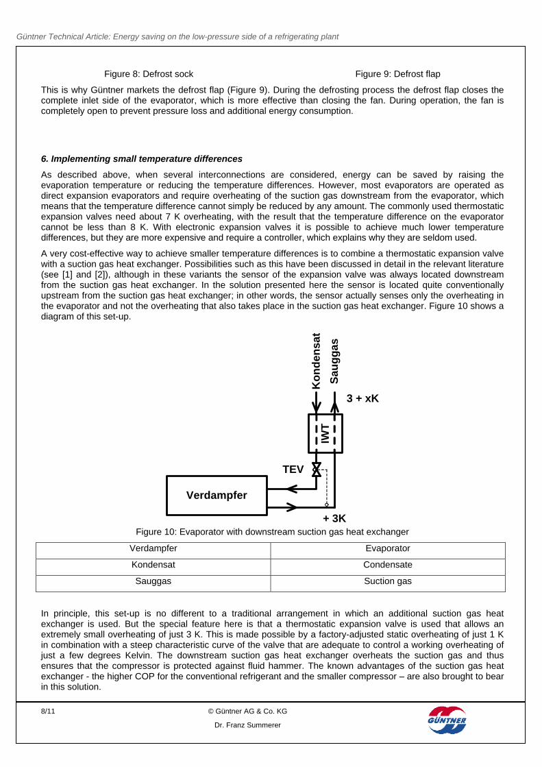
A very cost-effective way to achieve smaller temperature differences is to combine a thermostatic expansion valve with a suction gas heat exchanger. Possibilities such as this have been discussed in detail in the relevant literature (see [1] and [2]), although in these variants the sensor of the expansion valve was always located downstream from the suction gas heat exchanger. In the solution presented here the sensor is located quite conventionally upstream from the suction gas heat exchanger; in other words, the sensor actually senses only the overheating in the evaporator and not the overheating that also takes place in the suction gas heat exchanger. Figure 10 shows a diagram of this set-up.
Verdampfer
IWT
Ko
nd
ensa
t
Sau
gg
as
+ 3K
3 + xK
TEV
Figure 10: Evaporator with downstream suction gas heat exchanger
Verdampfer Evaporator
Kondensat Condensate
Sauggas Suction gas
In principle, this set-up is no different to a traditional arrangement in which an additional suction gas heat exchanger is used. But the special feature here is that a thermostatic expansion valve is used that allows an extremely small overheating of just 3 K. This is made possible by a factory-adjusted static overheating of just 1 K in combination with a steep characteristic curve of the valve that are adequate to control a working overheating of just a few degrees Kelvin. The downstream suction gas heat exchanger overheats the suction gas and thus ensures that the compressor is protected against fluid hammer. The known advantages of the suction gas heat exchanger - the higher COP for the conventional refrigerant and the smaller compressor – are also brought to bear in this solution.
Güntner Technical Article: Energy saving on the low-pressure side of a refrigerating plant
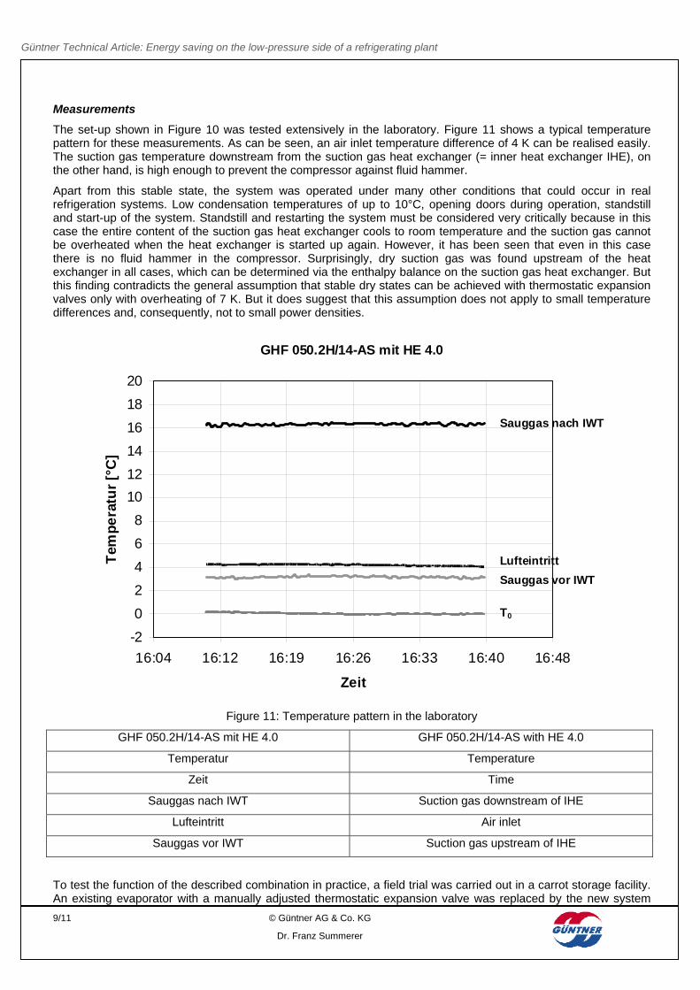
The set-up shown in Figure 10 was tested extensively in the laboratory. Figure 11 shows a typical temperature pattern for these measurements. As can be seen, an air inlet temperature difference of 4 K can be realised easily. The suction gas temperature downstream from the suction gas heat exchanger (= inner heat exchanger IHE), on the other hand, is high enough to prevent the compressor against fluid hammer.
Apart from this stable state, the system was operated under many other conditions that could occur in real refrigeration systems. Low condensation temperatures of up to 10°C, opening doors during operation, standstill and start-up of the system. Standstill and restarting the system must be considered very critically because in this case the entire content of the suction gas heat exchanger cools to room temperature and the suction gas cannot be overheated when the heat exchanger is started up again. However, it has been seen that even in this case there is no fluid hammer in the compressor. Surprisingly, dry suction gas was found upstream of the heat exchanger in all cases, which can be determined via the enthalpy balance on the suction gas heat exchanger. But this finding contradicts the general assumption that stable dry states can be achieved with thermostatic expansion valves only with overheating of 7 K. But it does suggest that this assumption does not apply to small temperature differences and, consequently, not to small power densities.
GHF 050.2H/14-AS mit HE 4.0
-2
0
2
4
6
8
10
12
14
16
18
20
16:04 16:12 16:19 16:26 16:33 16:40 16:48
Zeit
Tem
pe
ratu
r [°
C]
T0
Sauggas vor IWT
Sauggas nach IWT
Lufteintritt
Figure 11: Temperature pattern in the laboratory
GHF 050.2H/14-AS mit HE 4.0 GHF 050.2H/14-AS with HE 4.0
Temperatur Temperature
Zeit Time
Sauggas nach IWT Suction gas downstream of IHE
Lufteintritt Air inlet
Sauggas vor IWT Suction gas upstream of IHE
To test the function of the described combination in practice, a field trial was carried out in a carrot storage facility. An existing evaporator with a manually adjusted thermostatic expansion valve was replaced by the new system
Güntner Technical Article: Energy saving on the low-pressure side of a refrigerating plant
with the special valve and the suction gas heat exchanger. The system worked perfectly right from the outset without any further adjustments having to be made. However, it was not possible to implement temperature differences of less than 6 K because the compressor was over-dimensioned and uncontrolled. The evaporation temperature and the air temperature were lowered quickly until the compressor switched off again.
At this point it must be mentioned that a stationary operating state and a small temperature difference at the evaporator is possible only if the compressor capacity exactly matches the dimensioning conditions. Since compressors for fruit and vegetable cooling are often over-dimensioned to manage the higher capacities necessary during storage, this can be managed only with a controlled compressor or with corresponding control of the combined system. Precise and stable adjustment of the evaporation temperature is indispensable with small air inlet temperature differences of 4 to 6 K.
Güntner Technical Article: Energy saving on the low-pressure side of a refrigerating plant
There are various ways to save energy on the low-pressure side of a refrigeration system. But lowering the driving temperature difference by increasing the size of the evaporator does not produce the desired result in all cases. Especially in the plus range where high COP values can be assumed and no electric defrosting energy is needed, the power consumption of the evaporator fan plays an important role, so that a larger evaporator that is equipped with a more powerful fan can lead to higher energy consumption in spite of the smaller temperature difference. On the other hand, if the evaporator is optimised for a smaller temperature difference, the larger evaporator can pay for itself after just one year. It is not possible to make a blanket statement as to which evaporator is best; this must be examined on a case by case basis.
Small temperature differences at the evaporator can be achieved either with electronic expansion valves or with a combination of a suction gas heat exchanger and a special thermostatic expansion valve that is available from Güntner for evaporator capacities of up to 15 kW.
If additional devices, such as air rectifiers, are operated, attention must be paid that they do not cause pressure losses during operation.
If all the saving potentials are exploited, it is possible to achieve energy savings of 10 to 20% by optimising the low-pressure side.
8. Bibliography
[1] Tambovtsev, A., Quack, H.: Verbesserung von Verdampfern durch Auslagerung der Überhitzung, report from the German Refrigeration-Air Conditioning Congress in 2005, Würzburg, Volume II, German Society of Refrigeration and Air Conditioning, DKV, Stuttgart 2005.
[2] Döhlinger, M.:Geregelte Nachverdampfung im Wärmeaustauscher, Die Kälte- Und Klimatechnik, Issue 10/1990, Gentner Verlag, Stuttgart 1990.