EFFECTS OF POWER LINE OPERATING CONDITIONS ON NEARBY GAS PIPELINES Buletinul AGIR nr. 3/2012 iunie-august 1 E F F E C T S O F P O W E R L I N E O P E R A T I N G C O N D I T I O N S O N N E A R B Y G A S P I P E L I N E S Lecturer Eng. Denisa STET PhD 1 , Assoc. Prof. PhD. Eng. Dan D. MICU 1 , Eng. Levente CZUMBIL PhD Student 1 , Eng. Liviu ANCAS 2 1 Technical University of Cluj-Napoca, Electrical Engineering Faculty, Romania 2 S.N.T.G.N. Transgaz S.A, Medias R E Z U M A T . O b i e c t i v u l l u c r a r i i c o n s t a i n e v a l u a r e a t e n s i u n i l o r i n d u s e i n t r - o r e t e a d e d o u a c o n d u c t e s u b t e r a n e d e t r a n s p o r t a g a z e l o r n a t u r a l e , c a r e i m p a r t u n c o r i d o r d e d i s t r i b u t i e c o m u n c u o l i n i e e l e c t r i c a a e r i a n a d e i n a l t a t e n s i u n e ( L E A - I T ) , c u s c o p u l d e a d e t e r m i n a p r o b a b i l i t a t e a a p a r i t i e i f e n o m e n u l u i d e c o r o z i u n e i n c a z u l c e l o r d o u a c o n d u c t e m e t a l i c e ( C M ) . A n a l i z a i n t e r f e r e n t e l o r e l e c t r o m a g n e t i c e d i n t r e L E A - I T s i C M , s - a r e a l i z a t c u a j u t o r u l p r o g r a m u l u i p r o f e s i o n a l C D E G S a l S a f e E n g i n e e r i n g S e r v i c e s & t e c h n o l o g i e s l t d . P e n t r u o g e n e r a l i z a r e a s i t u a t i i l o r i n c a r e t r e b u i e e v a l u a t e t e n s i u n i l e i n d u s e , s - a u c o n s i d e r a t d i f e r i t e c o n d i t i i d e f u n c t i o n a r e a l e L E A - I T p r e c u m s i m o d e l e e c h i v a l e n t e d e s o l . C u v i n t e c h e i e : i nterferente in c.a., linie electrica de inalta tensiune, regim de functionare dezechilibrat, conducta metalica subterana A B S T R A C T . T h e a i m o f t h e p a p e r i s t o e v a l u a t e t h e i n d u c e d v o l t a g e s i n c a s e o f t w o u n d e r g r o u n d g a s p i p e l i n e s , w h i c h s h a r e a s a m e r i g h t o f w a y w i t h a n e x i s t i n g h i g h v o l t a g e p o w e r l i n e ( H V P L ) , i n o r d e r t o d e t e c t t h e p o s s i b i l i t y o f t h e A C c o r r o s i o n i n o c c u r r i n g i n t h o s e t w o p i p e l i n e s . T h e a n a l y s i s o f t h e i n t e r f e r e n c e s b e t w e e n H V P L a n d t h e u n d e r g r o u n d m e t a l l i c s t r u c t u r e s w a s d o i n g u s i n g t h e H I F R E Q M o d u l e o f C D E G S p r o f e s s i o n a l a n a l y s i s a n d m o d e l l i n g s o f t w a r e . D i f f e r e n t o p e r a t i n g c o n d i t i o n s a n d e q u i v a l e n t s o i l m o d e l s w e r e t a k i n g i n t o a c c o u n t f o r i n d u c e d v o l t a g e c a l c u l a t i o n . K e y w o r d s : AC interference, high voltage power lines, unbalanced regime, underground metallic pipeline 1. INTRODUCTION Electromagnetic interference study between high voltage power lines (HVPL) and nearby underground metallic pipelines (MPs) presents a great importance, given by the induced AC potentials. In most of the cases, to reduce the costs regarding the construction of gas, water or oil pipelines, they must share the same distribution corridor with HVPL. In this case, the pipelines located near power lines may capture a portion of the energy encompassed by the conductors’ paths, particularly under unfavourable circumstances such as long parallel exposures, unbalanced phase currents and power fault conditions. Induced AC voltage in these MP could be very dangerous on both the personnel that could be exposing to them and on their structural integrity, due to electrical corrosive effects. [1] Corrosion can cause serious failures, which lead to large economic loss, sometimes combined with environmental pollution, or risk of personnel injuries. In addition, the rate of corrosion dictates how long any process plant can be operated in a usefully and safely way. The most important steps in order to hinder or reduce the extent failures because of corrosion are sufficiently early detection, proper diagnosis and effective prevention and mitigation measures. Therefore, it is necessary to be maintains the values of the induced voltages below certain levels imposed by various standards and regulations. [2, 9] The interference between power transmission lines and pipeline generally consists of an inductive, a conductive and a capacitive part. The capacitive component is ignored for buried pipelines, whereas the conductive part is present only under fault conditions and affects the part of the pipeline that is close to the faulted structure. The inductive component is present during faults and normal operating conditions or in case of unbalanced phase currents. The objective of this study is to obtain the values of induced voltages in underground gas metallic pipelines, by a high voltage transmission line, using a professional analysis and modelling software. It will pursue a comparison between the induced voltages for different symmetrical and unbalanced HVPL current loads corresponding to steady-state conditions at different HVPL phase sequences and during a phase-to-ground fault conditions. Buletinul AGIR nr. 3/2012 ● iunie-august _____________________________________________________________________________________ 731
Transcript
EFFECTS OF POWER LINE OPERATING CONDITIONS ON NEARBY GAS PIPELINES
Buletinul AGIR nr. 3/2012 !"iunie-august 1
EFFECTS OF POWER LINE OPERATING CONDITIONS ON
NEARBY GAS PIPELINES
Lecturer Eng. Denisa STET PhD1, Assoc. Prof. PhD. Eng. Dan D. MICU1,
1Technical University of Cluj-Napoca, Electrical Engineering Faculty, Romania2S.N.T.G.N. Transgaz S.A, Medias
REZUMAT. Obiectivul lucrarii consta in evaluarea tensiunilor induse intr-o retea de doua conducte subterane de transport a
gazelor naturale, care impart un coridor de distributie comun cu o linie electrica aeriana de inalta tensiune (LEA-IT), cu
scopul de a determina probabilitatea aparitiei fenomenului de coroziune in cazul celor doua conducte metalice (CM).
Analiza interferentelor electromagnetice dintre LEA-IT si CM, s-a realizat cu ajutorul programului profesional CDEGS al Safe
Engineering Services & technologies ltd. Pentru o generalizare a situatiilor in care trebuie evaluate tensiunile induse, s-au
considerat diferite conditii de functionare ale LEA-IT precum si modele echivalente de sol.
Cuvinte cheie: interferente in c.a., linie electrica de inalta tensiune, regim de functionare dezechilibrat, conducta metalica subterana
ABSTRACT. The aim of the paper is to evaluate the induced voltages in case of two underground gas pipelines, which share
a same right of way with an existing high voltage power line (HVPL), in order to detect the possibility of the AC corrosion in
occurring in those two pipelines. The analysis of the interferences between HVPL and the underground metallic structures
was doing using the HIFREQ Module of CDEGS professional analysis and modelling software. Different operating conditions
and equivalent soil models were taking into account for induced voltage calculation.
Keywords: AC interference, high voltage power lines, unbalanced regime, underground metallic pipeline
1. INTRODUCTION
Electromagnetic interference study between high voltage power lines (HVPL) and nearby underground metallic pipelines (MPs) presents a great importance, given by the induced AC potentials. In most of the cases, to reduce the costs regarding the construction of gas, water or oil pipelines, they must share the same distribution corridor with HVPL. In this case, the pipelines located near power lines may capture a portion of the energy encompassed by the conductors’ paths, particularly under unfavourable circumstances such as long parallel exposures, unbalanced phase currents and power fault conditions. Induced AC voltage in these MP could be very dangerous on both the personnel that could be exposing to them and on their structural integrity, due to electrical corrosive effects. [1]
Corrosion can cause serious failures, which lead to large economic loss, sometimes combined with environmental pollution, or risk of personnel injuries. In addition, the rate of corrosion dictates how long any process plant can be operated in a usefully and safely way. The most important steps in order to hinder or reduce the extent failures because of corrosion are
sufficiently early detection, proper diagnosis and effective prevention and mitigation measures.
Therefore, it is necessary to be maintains the values of the induced voltages below certain levels imposed by various standards and regulations. [2, 9]
The interference between power transmission lines and pipeline generally consists of an inductive, a conductive and a capacitive part. The capacitive component is ignored for buried pipelines, whereas the conductive part is present only under fault conditions and affects the part of the pipeline that is close to the faulted structure. The inductive component is present during faults and normal operating conditions or in case of unbalanced phase currents.
The objective of this study is to obtain the values of induced voltages in underground gas metallic pipelines, by a high voltage transmission line, using a professional analysis and modelling software. It will pursue a comparison between the induced voltages for different symmetrical and unbalanced HVPL current loads corresponding to steady-state conditions at differentHVPL phase sequences and during a phase-to-ground fault conditions.
Buletinul AGIR nr. 3/2012 ● iunie-august_____________________________________________________________________________________
731
WORLD ENERGY SYSTEM CONFERENCE – WESC 2012 (World Energy System Conference)
Buletinul AGIR nr. 3/2012 !"iunie-august2
2. STUDIED INTERFERENCE PROBLEM
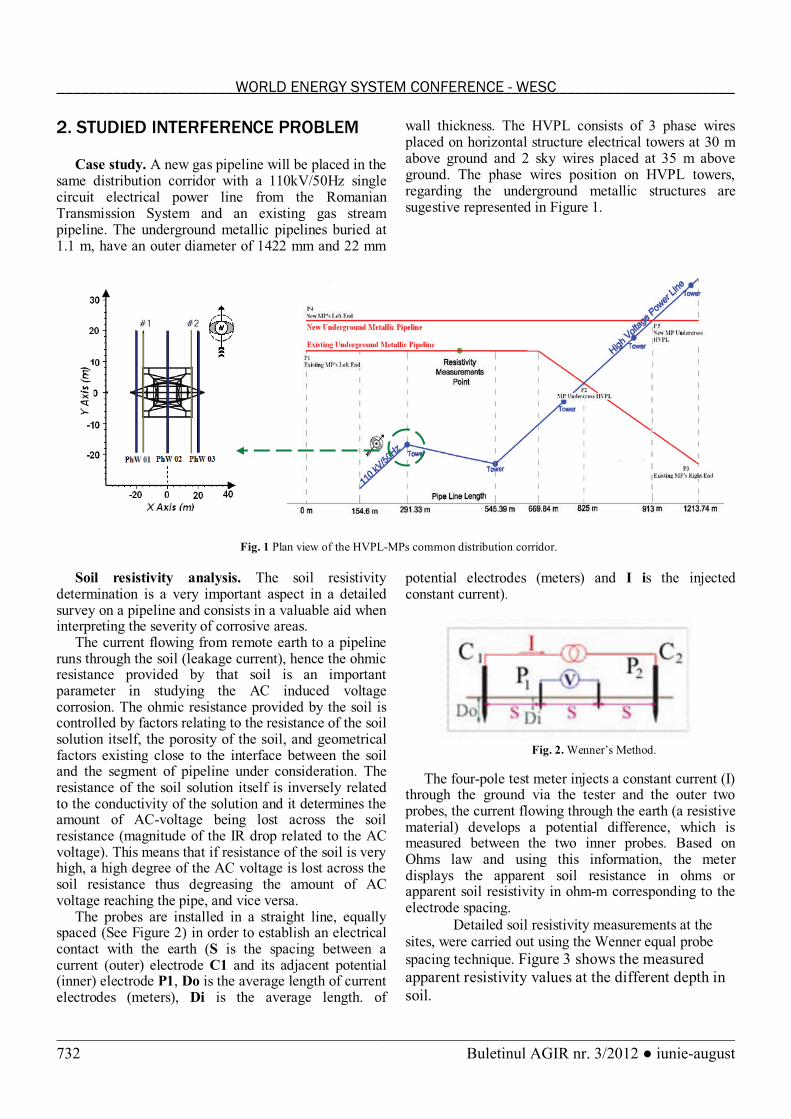
Case study. A new gas pipeline will be placed in the same distribution corridor with a 110kV/50Hz single circuit electrical power line from the RomanianTransmission System and an existing gas stream pipeline. The underground metallic pipelines buried at 1.1 m, have an outer diameter of 1422 mm and 22 mm
wall thickness. The HVPL consists of 3 phase wires placed on horizontal structure electrical towers at 30 m above ground and 2 sky wires placed at 35 m above ground. The phase wires position on HVPL towers, regarding the underground metallic structures are sugestive represented in Figure 1.
Fig. 1 Plan view of the HVPL-MPs common distribution corridor.
Soil resistivity analysis. The soil resistivity determination is a very important aspect in a detailed survey on a pipeline and consists in a valuable aid when interpreting the severity of corrosive areas.
The current flowing from remote earth to a pipeline runs through the soil (leakage current), hence the ohmic resistance provided by that soil is an important parameter in studying the AC induced voltage corrosion. The ohmic resistance provided by the soil iscontrolled by factors relating to the resistance of the soil solution itself, the porosity of the soil, and geometrical factors existing close to the interface between the soil and the segment of pipeline under consideration. The resistance of the soil solution itself is inversely related to the conductivity of the solution and it determines the amount of AC-voltage being lost across the soil resistance (magnitude of the IR drop related to the AC voltage). This means that if resistance of the soil is very high, a high degree of the AC voltage is lost across the soil resistance thus degreasing the amount of AC voltage reaching the pipe, and vice versa.
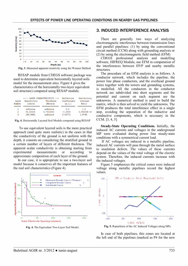
The probes are installed in a straight line, equally spaced (See Figure 2) in order to establish an electrical contact with the earth (S is the spacing between a current (outer) electrode C1 and its adjacent potential (inner) electrode P1, Do is the average length of current electrodes (meters), Di is the average length. of
potential electrodes (meters) and I is the injected constant current).
Fig. 2. Wenner’s Method.
The four-pole test meter injects a constant current (I) through the ground via the tester and the outer two probes, the current flowing through the earth (a resistive material) develops a potential difference, which is measured between the two inner probes. Based on Ohms law and using this information, the meter displays the apparent soil resistance in ohms or apparent soil resistivity in ohm-m corresponding to the electrode spacing.
Detailed soil resistivity measurements at the sites, were carried out using the Wenner equal probe
spacing technique. Figure 3 shows the measured
apparent resistivity values at the different depth in
soil.
_____________________________________________________________________________________WORLD ENERGY SYSTEM CONFERENCE - WESC
EFFECTS OF POWER LINE OPERATING CONDITIONS ON NEARBY GAS PIPELINES
Buletinul AGIR nr. 3/2012 !"iunie-august 3
Fig. 3. Measured apparent resistivity using the Wenner Method.
RESAP module from CDEGS software package was used to determine equivalent horizontally layered soils model for the measurement sites. Figure 4 gives the characteristics of the horizontally two-layer equivalent soil structure) computed using RESAP module.
Fig. 4. Horizontally Layered Soil Models computed using RESAP
To use equivalent layered soils is the more practical approach (and quite more realistic) in the cases in that the conductivity of the ground is not uniform with the depth, it consists on considering the stratified ground in a certain number of layers of different thickness. The
apparent scalar conductivity is obtaining starting from experimental measurements or according to approximate composition of each layer of the ground.
In our case, it is appropriate to use a two-layer soil model because it conserves all the important features of the real soil characteristics (Figure 4).
Fig. 4. The Equivalent Two-Layer Soil Model.
3. INDUCED INTERFERENCE ANALYSIS
There are generally two ways of analyzing electromagnetic interference between transmission lines and parallel pipelines: (1) by using the conventional circuit method (CCM) along with grounding analysis or (2) by using the electromagnetic field method (EFM)
CDEGS professional analysis and modelling software, HIFREQ Module, use EFM in computation of the interferences between HVP and nearby metallic structures.
The procedure of an EFM analysis is as follows. A conductor network, which includes the pipeline, the power line phase conductors, and the overhead ground wires together with the towers and grounding systems, is modelled. All the conductors in the conductor network are subdivided into short segments and the potential and current on each segment are the unknowns. A numerical method is used to build the matrix, which is then solved to yield the unknowns. The EFM produces the total interference effect in a single step, avoiding the separation of the inductive and conductive components, which is necessary in the CCM. [3, 4, 5]
Steady-State Operating Conditions. Initially, the induced AC currents and voltages in the underground MP were evaluated during power line steady-state conditions with a symmetrical current load.
If AC voltages are induced in a metallic pipeline, induced AC currents will pass through the metal surface to insulation defects. The values of these currents depend on the values of the total voltage of the electric system. Therefore, the induced currents increase with the induced voltages.
Figure 5 emphasizes the critical zones were induced voltage along metallic pipelines record the highest values.
Fig. 5. Repartition of the AC Induced Voltages along MPs.
In case of both pipelines, this zones are located at the left end of the pipelines (marked as P4 for the new
Buletinul AGIR nr. 3/2012 ● iunie-august_____________________________________________________________________________________
733
WORLD ENERGY SYSTEM CONFERENCE – WESC 2012 (World Energy System Conference)
Buletinul AGIR nr. 3/2012 !"iunie-august4
MP respectively P1 for the existing one) and where MPs undercross de HVPL (marked as P5: around 913 m from the new pipeline left end, respectively P2: around 825 m from the existing pipeline left end; see also Figure 1).
A detailed analysis, regarding the values of AC induced voltages along pipelines length is presented in Figure 6.
0
0.1
0.2
0.3
0.4
0.5
0.6
0.7
5 195 385 575 764 953 1141 1330
P ipe P osition [m]
Ind
uc
ed
Vo
lta
ge
New P ipeline E x is ting P ipeline
Fig. 6. Values of the AC Induced Voltages along MPs
Studies of the electromagnetic field around HVPL had shown that different phase-sequences influence significantly the distribution of the electric and magnetic field around power lines. Regarding to this, in order to evaluate the influence on induced interferences on MP, the authors have investigated all six possible phase-sequences combinations. As result, two distinguished phase sequence: the positive order (e.g. ABC) and the negative order (e.g. BAC) phase-sequence were highlighted, regarding the levels of
induced currents and voltages in MP (Phase A: 00350! ;
Phase B: 0120350 "! ; Phase C: 0120350! ).Table 1
Induced voltages in MP in case of different phase-sequencies
Phase-Sequence
Max. Induced
Voltage [V]
New MP Existing MP
Positive Order (ABC,
BCA, CAB)
0.590947 0.591513
Negative Order (ACB,
BAC, CBA)
0.384659 0.385538
Deviation [%]0.10 0.23
Romanian statistics mentioned that, the power flow through an 110kV power line varies between 27–55MW. Therefore, to investigate the induced AC potential levels, that can occur for different power flows, the symmetrical current load on HVPL was considered in the range of 200-600A.
Fig. 7a. AC Induced Voltages along the New MP, in case of different current load values
Fig. 7b. AC Induced Voltages along the Exising MP, in case
of different current load values
Accordingly to Figure 7, the levels of the induced voltages in nearby metallic structures, increases with the value of current load. In case of new pipeline, an increase of the load current, from 350A to 600A, leads to an increase of the maximum value of the AC induces voltage with 71%. In these conditions and with an appropriate polyethylene insulation of MP, the corrosion likelihood in the metallic structure is reduced. The critical values of the induced voltages, regarding the start of electrochemical corrosion reaction, are around 1200 mV [6].
Previous studies [7, 8] had shown that in case of perfect parallel HVPL-MP exposure, the graphical representation of the induced voltage values along the pipeline, presents a “V” curve with maximum values obtained at metallic structure ends.
Because different orientation of the electromagnetic field on both sides of HVPL, in case of the studied metallic pipelines, the right side “V” curve is not complete as an effect of the higher electromagnetic interference influence from the left side of the HVPL.
Unbalanced Load Operating Condition. Usually, in practice, unbalanced current loads are present. These unbalanced current loads can have significant influence on the AC interference levels induced in the nearby metallic structures such as underground MP. [7]
_____________________________________________________________________________________WORLD ENERGY SYSTEM CONFERENCE - WESC
EFFECTS OF POWER LINE OPERATING CONDITIONS ON NEARBY GAS PIPELINES
Buletinul AGIR nr. 3/2012 !"iunie-august 5
Different energization conditions on the phase wireare expresed using the following quality factors, based on symmetrical components of the current phasors:
negative-sequence coefficient ( "
Ik ), zero-sequence
coefficient ( 0Ik ) and total unbalance coefficient ( Ik ):
#
""$
I
Ik I [%] (1)
#
$I
Ik I
00 [%] (2)
0III kkk #$
" [%] (3)
Considering a 2% for "
Ik and 0Ik the AC induced
voltage in underground metallic pipeline was computed
for all possible phase-sequences combinations; Table 2presents the unbalanced current loads for each HVPL phase wire (with 500A symmetrical current load).
Table 2
Values of the Phase Current
Phase Wire Current load [A] Current phase [deg.]
Phase A 505 0
Phase B 490 -120
Phase C 490 120
In comparison with symetrical load where phase-sequence had almost no influence, in case of unbalance-currents situations, it has a significant effect on induced voltage variation (Figure 8 and 9).
0
0,1
0,2
0,3
0,4
0,5
0,6
0,7
5 194 382 571 760 948 1137 1326
Pipe Position [m]
Ind
uce
d V
olt
ag
e [
V]
RST RTS
0
0,2
0,4
0,6
0,8
1
1,2
1,4
5 195 385 575 764 953 1141 1330
Pipe Position [m]
Ind
uce
d V
olt
ag
e [
V]
RST RTS SRT STR TRS TSR
Fig. 8. AC Induced Voltages along the New MP, in case of different phase sequencies
0
0,05
0,1
0,15
0,2
0,25
0,3
0,35
0,4
0,45
5 195 385 575 764 953 1141 1330
Pipe Position [m]
Ind
uce
d V
olt
ag
e [
V]
RST RTS
0
0,2
0,4
0,6
0,8
1
1,2
5 195 385 575 764 953 1141 1330
Pipe Position [m]
Ind
uce
d V
olt
ag
e [
V]
RST RTS SRT STR TRS TSR
Fig. 9a. AC Induced Voltages along the Existing MP I case of different phase sequencies
When the most loaded phase wire is in position 1 or 2 (see Figure 2) regarding the MPs, however the shape of induced voltage graphical representation is similar, the induced voltages records values that exceeds the limit voltage level for electrochimical corossion (Figure 9). On the other hand, when the most loaded phase wire is in position 3 tha maximum induced voltage levels are obtained at the MP right side (at point P3) and the voltage peack (acording to
point P2) is diminuated, as an effect that now a higher electromagnetic interference influence is recorded on the right side of the HVPL.
It can be observe that the influence of the HVPL on new MP, regarding the values of the AC induced voltages, is more pronounce instead of the existing MP. This is because the New MP crosses the HVPL under a 30°, unlike the situation of the existing Mpwhich cross the HVPL almost perpendiculary.
Buletinul AGIR nr. 3/2012 ● iunie-august_____________________________________________________________________________________
735
WORLD ENERGY SYSTEM CONFERENCE – WESC 2012 (World Energy System Conference)
Buletinul AGIR nr. 3/2012 !"iunie-august6
Phase-to-Ground Fault. If a phase-to-ground fault appears far away from the common distribution corridor, so that the conductive coupling between HVPL and MP can be neglected as well as in steady-state operating conditions.
In Figure 10 and Figure 11 there are presented the values of the AC induces voltages recorded during a phase-to-ground fault appeared one by one on each
HVPL phase wire.
0
20
40
60
80
100
120
140
160
180
5 195 385 575 764 953 1141 1330
P ipe P osition [m]
Ind
uc
ed
Vo
lta
ge
New pipeline E x is ting pipeline
Fig. 10. AC Induced Voltages along the new MP, in case of a
phase-to-ground fault (on phae S)
0
20
40
60
80
100
120
140
160
180
5 195 385 575 764 953 1141 1330
Pipe Position [m]
Ind
uce
d V
olt
ag
e [
V]
Fault on R Fault on S Fault on T
Fig. 11. AC Induced Voltages along the new MP in case of
phase-to-ground fault (on different phase)
In this case a classical ”V” curve is obtained, because the influence on the generated electromagnetic field of the unfaulted phases are negligible in comparison with the faulted phase. The maximum value of the induced values could varies with almost 3 % with the position of faulted phase regarding MPs.
In case of these extreme conditions, the induced voltages in the metallic structures generate dangerous situations from corrosion and personal safety point of view, and also proper mitigation measures are imposed (e.g. mitigation wires, grounding electrodes).
4. CONCLUSIONS
The analysis of presented HVPL-MP interference problem, for different power line operating conditions, has outlined the situations when the induced voltages generates dangerous situations from corrosion and personal safety point of view.
BIBLIOGRAPHY
[1] G. Christoforidis, D. Labridis, Inductive Interference on pipelines buried in multilayer soil due to magnetic fields from nearby faulted power lines, IEEE Transaction on Electromagnetic Compatibility, Vol. 47, No. 2, pp. 254-262, May 2005.[2] *** prEN 50443: Effects of Electromagnetic Interference on Pipelines cased by High Voltage A.C. Railway Systems and/or High Voltage A.C. Power Supply Systems, CENELEC, European Committe for Electrotechnical Standardization, ICS 33.040.20; 33.100.01, January, 2009.[3] Ma, J., Dawalibi, F.P., Recent Advances in Electromagnetic Analysis in Common Corridors, proceedings of 4th Asia-Pacific Conference on Environmental Electromagnetic (CEEM), Dalian, China, August 1-4, 2006, pp. 409-418. [4] Li, Y. Dawalibi, F. P. and Ma, J., Electromagnetic
interference caused by a power system network and a
neighbouring, proceedings of the 62nd Annual Meeting of the American Power Conference, Chicago, 2000, pp. 311-316.
[5] F. P. Dawalibi, J. Ma, and Y. Li, Mechanisms of
electromagnetic interference between electrical networks and
neighboring metallic utilities, Proceedings of the 61st Annual Meeting of the American Power Conference, Chicago, 1999, pp.
150-155.[6] Lingvay, I#$" %#&#$"Study of Corrosion for Some Iron Steels Given by the Alternative Stray Currents , EUROCORR ‘97, Trondheim, Norway, 22-25 September, 1997, vol. I, pp. 635-640.[7] !"#$%&'(#!"!"#)*+,(#-"#./,01*2(#-"#!343135%(#6"#.&+235,Analysis of Electrical Interference from Power Lines to Gas Pipelines, During Different Cases of Unbalanced Phase Currents, 4th International Conference on Electromagnetic Fields, Health and Environment (EHE), 26-28 mai 2011, Coimbra Portugalia, ISBN: 978-972-8822-22-4.[8] D. D. Micu, L. Czumbil., A. Ceclan, L. Darabant,Accurate methods for solving electromagnetic interference problems between power lines and underground metallic pipelines, 44th International Universities Power Engineering Conference, UPEC 2009, Glasgow, Scotland, IEEExplore, 1-4September 2009, ISBN 978-0-947649-44-9.[9] *** Mitigation of Alternating Current and Lighting Effects
on Metallic Structures and Corossion Control Systems, NACE
Stabdard RP0177-95.
Aknowledgment
This paper was supported by the project TE_253/2010_CNCSIS project – “Modeling, Prediction and Design Solutions, with Maximum
Effectiveness, for Reducing the Impact of Stray Currents on Underground Metallic Gas Pipelines”, No. 34/2010, project co-funded from
European Social Fund through Sectorial Operational Program Human Resources 2007-20
_____________________________________________________________________________________WORLD ENERGY SYSTEM CONFERENCE - WESC