Japan Advanced Institute of Science and Technology JAIST Repository https://dspace.jaist.ac.jp/ Title Efficient Equalization Hardware Architecture for SC-FDMA Systems without Cyclic Prefix Author(s) Ferdian, Rian; Anwar, Khoirul; Adiono, Trio Citation 2012 International Symposium on Communications and Information Technologies (ISCIT): 936-941 Issue Date 2012-10 Type Conference Paper Text version author URL http://hdl.handle.net/10119/10897 Rights This is the author's version of the work. Copyright (C) 2012 IEEE. 2012 International Symposium on Communications and Information Technologies (ISCIT), 2012, 936-941. Personal use of this material is permitted. Permission from IEEE must be obtained for all other uses, in any current or future media, including reprinting/republishing this material for advertising or promotional purposes, creating new collective works, for resale or redistribution to servers or lists, or reuse of any copyrighted component of this work in other works. Description
Transcript
Japan Advanced Institute of Science and Technology
JAIST Repositoryhttps://dspace.jaist.ac.jp/
TitleEfficient Equalization Hardware Architecture for
∗∗School of Information Science, Japan Advanced Institute of Science and Technology (JAIST)Asahidai 1-1, Nomi, Ishikawa, Japan 923–1211, E-mail: [email protected]
Abstract—Single carrier frequency domain multiple access(SC-FDMA) system achieves better spectral efficiency when cyclicprefix (CP) is not transmitted. However, the chained turboequalization (CHATUE) algorithm, an equalizer required to bothequalize the multipath fading effect and cancel the inter-block in-terference of SC-FDMA without CP, requires high computationalcomplexity due to the non-circulant structure of the past andthe future interference matrices. This paper proposes efficienthardware architecture based on systolic architecture for practicalimplementation. The main idea is to minimize the numberof required processing elements by utilizing efficient resourcessharing method while exploiting concurrency of the processing.A new computation method using masking matrices is introducedto obtain interference matrix from its corresponding circulantchannel matrix. The results with fixed point computation showthat the computational complexity can be significantly reducedup to 96% for practical implementation without significantdegradation in bit-error-rate (BER) performances.
I. INTRODUCTION
The need for a wireless transmission system with moreefficient spectrum rises along with the significant growth inthe number of wireless communication users. Transmissionsystem without cyclic prefix (CP) or guard interval (GI) isone of the solutions to achieve a better efficiency in spectrum.However, the absence of CP or GI causes additional interfer-ence, i.e., inter-block interference (IBI) from past and futureblocks, beside the inter-symbol interference (ISI) due to themultipath fading effect.
Chained turbo equalization (CHATUE) algorithm offers alow computational complexity method to equalize the bothISI and IBI in block transmission systems without CP or GI[1]. The detail analysis and advantages over the standard blocktransmission systems with CP as well as its impact due to theDoppler effect has also been investigated in [2]. Furthermore,for practical broadband application, CHATUE algorithm isapplied to SC-FDMA systems in [3] and [4]. In order tominimize the computational complexity, CHATUE algorithmutilizes matrix J to form a circulant structure of the (current)channel matrix. However, the introduction of matrix J is still
This research has been supported in part by Chubu Electric Co. Ltd.,(Kinki) Mobile Radio Center (MRC), Inc., Japan and in part by Ministry ofTelecommunications and Informatics, Indonesia. This research is conductedwhen the first author was a visiting research student in JAIST, Ishikawa, Japan.
Encoder Interleaver BPSK FFTK
Sub Carrier Mapping
IFFTMSource
FFTM
Sub Carrier Demapping
IFFTK+
SoftReplica
SC-MMSE Coefficient
Compuation
SC-MMSE FilteringDeinterleaverDecoder
+ interleaver
Equalizer
+
-
J
Current LLR Past LLR Future LLR
Ci;t
bi
bêi
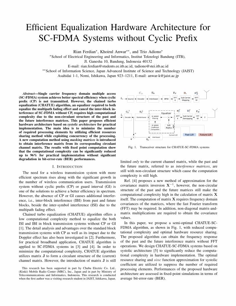
Fig. 1. Transceiver structure for CHATUE-SC-FDMA systems
limited only to the current channel matrix, while the past andthe future matrix, referred to as interference matrices, arestill with non-circulant structure which cause the computationcomplexity is still high.
Ref. [4] proposes a new method of approximation for thecovariance matrix inversion X−1, however, the non-circularstructute of the past and the future matrices still make thecomputational complexity high in the calculation of matrix Xitself. The computation of matrix X requires frequency domaincovariances of the matrices, where the fast Fourier transform(FFT) may be required. In addition, non-diagonal matrix-and-matrix multiplications are required to obtain the covariancevalues.
In this paper, we propose a semi-optimal CHATUE-SC-FDMA algorithm, as shown in Fig. 1, with reduced compu-tational complexity and optimal hardware resource sharing.The proposed algorithm can obtain the frequency responseof the past and the future interference matrix without FFToperations. We design CHATUE-SC-FDMA systems based onsystolic architecture [5] to significantly reduce the computa-tional complexity in hardware implementation. The optimalresource sharing and sinc function approximation for systoliccoefficient are utilized to suppress the number of requiredprocessing elements. Performances of the proposed hardwarearchitecture are assessed in fixed-point simulations in terms ofaverage bit-error-rate (BER).
II. SYSTEM MODEL
In this paper, we assume CHATUE-SC-FDMA systemswithout doped-accumulator (DA) [3] with a block diagramas shown in Fig. 1. At the transmitter, the information bitsfor the i-th user at t-th block are encoded by Ci,t, interleavedby Πi,t, and modulated through K-points FFT (FK), sub-carrier mapped and M -point inverse FFT (FH
M ) to producevector signal si,t, s′i,t−1, and s′′i,t+1. The notations (•)′ and(•)′′ indicate the past and the future blocks relative to currentblock, respectively.
The SC-FDMA blocks is transmitted without CP over themulti-path block Rayleigh fading channel.1 At the receiver,the received signal is affected by three channel matricesand four interference matrices. For the current block, thecomputation involves the current channel matrix (Hi,t), thepast interference matrix from past block (H′i,t−1), and futureinterference matrix from future block (H′′i,t+1). The detailsstructure of the channel and interference matrices are discussedin [2].
We assume a perfect user sub-carrier mapping such thatthe interference from other users is negligible and hence, thereceived signal for the i-th user can be expressed as
ri,t = FHKDT
i FMJHi,tFHMDiFKsi,t
+FHKDT
i FMJH′i,t−1FHMDiFKs
′i,t−1
+FHKDT
i FMJH′′i,t+1FHMDiFKs
′′i,t+1 + n, (1)
where Di represents the sub-carrier mapping matrix, DTi
represents sub-carrier de-mapping matrix with (•)T denotesa matrix transpose operation and n is the additive whiteGaussian noise vector with variance of σ2
n.In this paper, Di is assumed to be the same over the current,
the past and the future blocks for each user. si,t is Binaryphase shift keying (BPSK) modulated block with in total of 4users and M = 512.2 The total number of path is 20 and 64with equal average power. The encoder Ci,t is a very simplememory 1 convolutional code with generator polynomial ofG = [3, 2]8.3 A fixed point model is used to observe the bit-width required by each variable in the CHATUE-SC-FDMAcomputation. The results are used as the baseline to define thehardware’s bit specification.
III. OPTIMIZED CHATUE-SC-FDMA ALGORITHM
The computations of CHATUE-SC-FDMA algorithm canbe divided into three parts: soft cancellation, SC-MMSEcoefficients computation, and SC-MMSE filtering. As noted inSection I, the circulant structure of interference matrices is notachieved even with matrix J multiplication. As the solution,we introduce the use of column and row masking matrix MC
and MR, respectively, to retrieve interference matrix from its
1The channel gains remain the same in a block.2Extension to higher order modulations such as QPSK or 64-QAM is
straightforward.3The decoder is Bahl-Cocke-Jelinek-Raviv (BCJR) algorithm with log-max
operation (the exponent is taken into account) [6].
L-1
L-1
L-1
L-1
Fig. 2. Structure of column and row masking matrices
corresponding channel matrix. The mathematical derivation forpast interference matrix is described as
JH′i,t−1 = M′RJHi,t−1M
′C , (2)
and for the future interference matrix as
JH′′i,t+1 = M′′RJHi,t+1M
′′C . (3)
The structure of column and row masking matrices areshown in Fig. 2, where L is the number of path in the channel.From the figure it can be noted that M′
R, M′C and M′′
R arehaving the same structure.
A. Soft Cancellation
Soft cancellation takes a major part in ISI and IBI compo-nents removal. The equalizer creates replica of the receivedsignal based on a priori information provided by the decoderas well from its neighbouring decoders in the form of log-likelihood ratio (LLR). In total, there are three LLR areinvolved in the soft cancellation computation, a posteriori LLRL′p,c−1
i,t−1
from the past decoder, a posteriori LLR L′′p,c−1
i,t+1
from future decoder, and extrinsic LLR Le,c−1i,t
from the currentdecoder. The details of soft-estimate si,t for CHATUE-SC-FDMA have been described in [4].
By using the channel matrices (from the channel estimator),the soft replica ri,t of the received signal ri,t is obtained as
ri,t = FHKDT
i FMJHi,tFHMDiFK si,t +
FHKDT
i FMJH′i,t−1FHMDiFK s
′i,t−1 +
FHKDT
i FMJH′′i,t+1FHMDiFK s
′′i,t+1. (4)
Since JHi,t is circulant, the matrix Hi,t, the frequencyresponse or current channel matrix,
Hi,t = FMJHi,tFHM . (5)
is a diagonal matrix. Computational complexity for this matrixis as simple as FFT vector problem for h[1]t , where h
[1]t is
the first column vector of the circulant current channel matrixJHi,t [7].
Because the channel frequency response of the past andfuture interference matrices do not reduce the computation
complexity, we apply the masking matrices technique in (2)and (3) to compute the past and future parts in (4). For thepast block, we can modify as
FHKDT
i FMJH′i,t−1FHMDiFK
= FHKDT
i FMM′RJHi,t−1M
′CFH
MDiFK
= FHKDT
i FMM′RFH
MFMJHi,t−1FHMFMM′
CFHMDiFK
= FHKDT
i M′RH′i,t−1M
′CDiFK , (6)
where M′C and M′
R are the response frequency of maskingmatrix as
M′R = FMM′
RFHM , (7)
andM′
C = FMM′CFH
M , (8)
respectively.4
Eqs. (7) and (8) can be considered as filter operator byobserving the structure of masking matrices from Fig. 2.Furthermore, it can also be noted that M
′
R, M′C , and M′′
R actas high-pass filter, while M′′
C as low-pass filter. The diagonaland real property of the masking matrices provides a circulantand hermitian structure of its frequency response. Finally, (4)for soft replica computation can be re-expressed as
ri,t = FHKDT
i Hi,tDiFK si,t +
FHKDT
i M′RHi,t−1M
′CDiFK s
′i,t−1 +
FHKDT
i M′′RHi,t+1M
′′CDiFK s
′′i,t+1. (9)
Here, the matrices Hi,t−1 and Hi,t+1 can be get fromequalizer past or equalizer future when computing their currentblock. Hence, we obtain the benefit that the M points FFTcomputation can be avoided for past and future part compu-tation by replacing them with two filter operation from themasking matrix. Finally, the soft cancellation is performed bysubtracting the received data with the its soft replica as
ri,t = ri,t − ri,t, (10)
where residue ri,t is further minimized using SC-MMSE filter.
B. SC-MMSE Filters Coefficients
The SC-MMSE filter should update the coefficients accord-ing its data input, where coefficients is
X ≈ Λi,tΦi,tΦHi,t + Λ′i,t−1
1
Ktr(Φ′i,t−1Φ
′Hi,t−1)IK
+Λ′′i,t+1
1
Ktr(Φ′′i,t+1Φ
′′Hi,t+1)IK
+σ2i
1
Ktr(DT
i JJTDi)IK . (11)
where, σi is the noise variance for the i-th user as
σ2i =
K
Mσ2n. (12)
The covariance matrix of modulation level is defined as
Λi,t = diag{(1− |si,t|2)I}, (13)
4Modification for future block is not shown here due to the space limitation.
and the equivalent frequency domain channel matrix is
Φi,t = DTi FMJHi,tF
HMDi. (14)
To minimize the computational complexity for the covari-ance of interenference matrices, similarly we apply (2) and (3)to Φ′i,t−1 and Φ′′i,t+1 as
Φ′i,t−1 = DTi FMJHi,tF
HMDi
= DTi M′
RHi,tM′CDi. (15)
By carefully observing (15), the covariance matrix computa-tion for the past and the future interference matrix still requiresheavy matrix-matrix multiplications. However, we found thatonly the diagonal parts of the covariance matrix that makeseffect to matrix X due to trace operator. Here, we exploitthe cyclic shifts property of trace operation to minimize therequired computation by modifying
tr(Φ′i,t−1Φ′Hi,t−1)
= tr(DTi M′
RHi,t−1M′CDiD
Ti M′
RHHi,t−1M
′CDi)
= tr(M′CDiD
Ti M′
RHi,t−1M′CDiD
Ti M′
RHHi,t−1)
= tr(PHi,t−1PHHi,t−1)
= tr(diag(PHi,t−1P)HHi,t−1), (16)
whereP = M′
CDiDTi M′
R. (17)
Using P, let’s define
W = diag(PHi,t−1P). (18)
Matrix P can be pre-computed, the element of which isa constant that varies depends on the sub-carrier mappingmatrix, because matrix P inherits Hermitian and circulantstructure from matrix M′
C and M′R. Consequently, diagonal
elements of matrix W can be derived as
W(k, k) =
M∑i=1
P(i, k)P(k, i)Hi,t−1(i, i)
=
M∑i=1
|P(i, k)|2Hi,t−1(i, i)
=
M∑i=1
|P([i−K+1] mod M, 1)|2Hi,t−1(i, i).(19)
Eq. (19) shows that the computation for diagonal matrix Wcan be performed by circular convolution of vector p whichis a vector taken from the first column of matrix P.
C. SC-MMSE FilteringThe final output of SC-MMSE filter is [2]
zi,t = (IK + Γi,tSi,t)−1[Γi,tsi,t + FH
KΦHi,tX
−1FK ri,t] (20)
with Γi,t
Γi,t = diag[FHKΦH
i,tX−1Φi,tFK ], (21)
and matrix Si,t of
Si,t = diag|si,t|2 × IK , (22)
where IK is the K ×K size identity matrix.
Column Filter
Row Filter
Column Filter
Row Filter
Σ
-
FFTK
FFTK
FFTK
Fig. 3. Soft cancellation block diagram
IV. HARDWARE ARCHITECTURE
The proposed algorithm presented in section III contributesvery efficient computation where only diagonal and circulantmatrix are involved. Furthermore, the circulant matrices canbe further simplified by performing cyclic convolution, whilethe diagonal matrices can be implemented with point wisemultiplications.
A. Hardware Architecture for Soft Cancellation
Based on the results in (9) and (10), the block diagram forsoft cancellation can be designed as in Fig. 3. The channelsfrequency response is assumed unchanged in each iteration,and hence it can be pre-computed. The computation of thecurrent block consists only the diagonal matrix multiplication,which can be implemented with a single multiplier, as theFFTK’s output data in series. On the other hand, the compu-tations for the past and the future parts consist of two cyclicconvolution from row/column filters and one diagonal matrixmultiplication from the channel matrices.
A column filter is a combination of sub-carrier mapping ma-trix multiplication with a column masking frequency responsematrix, denoted as M′
CDi or M′′CDi. Sub-carrier mapping
matrix affect the matrix’s size reduction to K × M , whichmeans the column filter can be done in K time iterations asone iteration for one column. The structure of column filtermatrix for user 1 is shown in Fig. 4(a).5 The flow of columnfilter matrix can be mapped into systolic architecture wherethe data flow is shown by the systolic space and time diagram.Fig. 4(b) shows the systolic architecture type applied whichbroadcast inputs, move results and weights stay.
A row filter is a result of row masking matrix multiplicationwith the sub-carrier de-mapping matrix, DT
i M′R or DT
i M′′R.
These matrices have M ×K size as shown Fig. 5(a). For totalof K iterations, in each iteration a complete row computationshould performed. Thus, we select the systolic type with fan-in results, move inputs, and weight stays, where the space and
5Note that user 1 in this figure is just for an example to show the systolicspace time representation of column filter. The same assumption applies forrow filter.
20 40 60 80 100 120
100
200
300
400
500
(a)
Y(1) Y(2)Y(K-N/2+1)
Y(K+N/2)
Y(K+N/2-1)
Y(K+N/2-2)
Y(K-N/2+2)
Y(K+N)Y(K+N/2+1)Y(K+N/2+2)
Y(K+N/2+3) Y(K+N-1)
Time Axis
Proc
esso
r Axi
s
1
2
3
N
N-1N-2
1 2 3 N/2N/2-1 N/2+1 N/2+2 K
X1 X2 X3 X(K)X(K-1)X(K-2)
(b)
Fig. 4. (a) Matrix DTi M′R or DT
i M′′C for user 1, (b) The systolic spacetime representation for column filter
i M′′C for user 1, (b) The systolic spacetime representation for row filter
C1 C2 C3 CNCN-1
CIRCULAR BUFFER K + N
N Processing Elemets
N Processing Elemets
C1 C2 C3 CNCN-1
Fig. 6. Systolic architecture for row and column filter
ΣΣ
Inverse
P Vector Convolution past
P Vector Convolution future
H( X )
1(X)
Fig. 7. Block Diagram to compute X−1
time diagram is shown in Fig. 5(b). While the parallel com-putation for input data is processed for each row computation,the input data should be stored in registers. Those registers isimplemented as a circular buffer due to the merit of circulantmasking matrix frequency response. The buffer has size ofK +N , where N is the number of filter’s coefficients.
Finally, the hardware architecture for the past/future blockscomputation can be designed as in Fig. 6. One processing ele-ment (PE) is implemented as: one register for filter coefficient,one adder, and one multiplier. In details, Section V investigatesthe effect of reducing the PE.
B. Hardware Architecture for matrix X computation
As shown in (11), matrix X comprises the noise, frequencydomain components of interferences form the past and thefuture blocks and the frequency domain componenents of thecurrent block [4]. The computation of its inversion is shownin the block diagram of Fig. 7. It should be noted here thatsince the computation for noise term can be considered asmultiplication of two scalars, we use only a single multiplier,while the variable tr(DT
i JJTDi) can be pre-computed as aconstant. Similarly, the diagonal matrix-by-matrix multiplica-tion for the current channel covariance computation can alsobe implemented using a single multiplier because the outputdata are in series.
100 200 300 400 500
100
200
300
400
500
Fig. 8. The shape of matrix P for user 1
Y(K)
X(K+N)X(K+N-1) X(K+N-2)
X(K+1)
X(K+N-3)
X(K+N+1)X(K+N+2)
X(K+N+3)
Proc
esso
r Axi
s
123
2N2N-12N-2
1 2 3 N+1 N+2 KY(1)
X(N)
Y(2) Y(3) Y(N+1) Y(N+2)
X(N+1)X(N+2)
X(K-N+1)
K-1K-2K-3
Fig. 9. Space and time representation for vector p convolutions
The past and future covariance computations are imple-mented based on (16), where one circular convolution andone diagonal matrix multiplication are needed. The circularconvolution can be performed in K iterations because matrixP has K non-zero columns and K non-zero rows as plottedin Fig. 8.
We apply the same systolic architecture type as for row filterto this vector p circular convolution, which is fan-in results,move inputs, and weights stay, as shown in Fig. 9. However,the number of processing element required for this circularconvolution is 2N , because matrix P is resulted from thecolumn filter with row filter, as N is the number of processingelements in those masking filters.
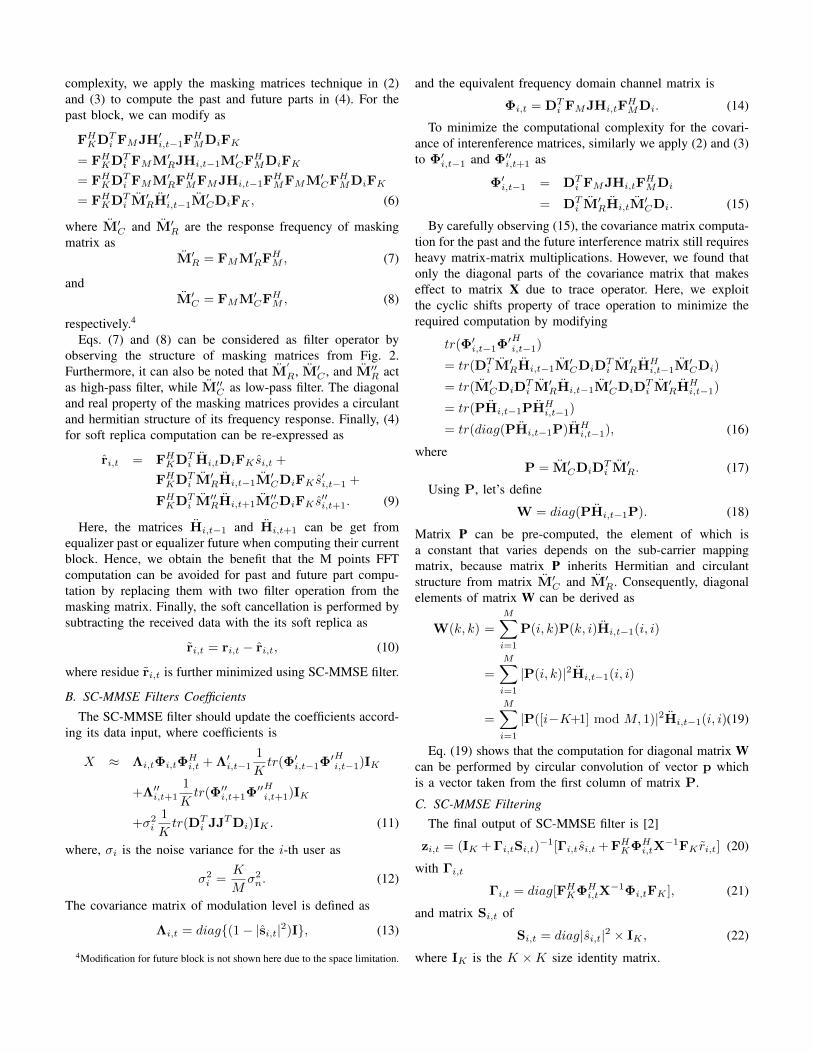
The diagonal matrix multiplication for the past/future co-variance computation can be realized with a single multiplier,since the output data from circular convolution are in series.The trace operator is implemented with one accumulator andlog(K) right shifter for 1/K operation. It results in hardwarearchitecture for the past/future covariance matrix computationas shown in Fig. 10.
V. SIMULATION RESULTS
To investigate the effect of bit-width reduction, we conductfixed point simulations to find the minimum required bit-widthfor hardware implementation. We assume the channel is 64-path block Rayleigh fading channels (the channel gains donot change within a block) with average equal power. Theperformance is presented in Fig. 11 in terms of average BER(over the fading channel realizations) vs. average energy bitper noise, Eb/N0 (dB). From the figure, we found that theminimum bit-width is 9 bits since the BER degradation is
C1 C2 C3 C2NC2N-1
CIRCULAR BUFFER K + 2N
Y=(X)*
>> (LOG (K))
Fig. 10. Systolic architecture for matrix X computation
Fig. 11. Bit Error Rate Performance with difference fixed point setting
large when the bit-width is set less than 8 bits, which finallyfails at bit-width of 6 bits.
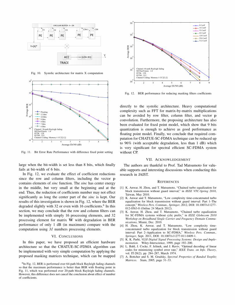
In Fig. 12, we evaluate the effect of coefficient reductionssince the row and column filters, including the vector pcontains elements of sinc function. The sinc has center energyin the middle, but very small at the beginning and at theend. Thus, the reduction of coefficients number may not effectsignificantly as long the center part of the sinc is kept. Ourresults of this investigation is shown in Fig. 12, where the BERdegraded slightly with 32 or even with 16 coefficients.6 In thissection, we may conclude that the row and column filters canbe implemented with simply 16 processing elements, and 32processing element for matrix W with degradation in BERperformance of only 1 dB (in maximum) compare with thecomputation using M numbers processing elements.
VI. CONCLUSIONS
In this paper, we have proposed an efficient hardwarearchitecture so that the CHATUE-SC-FDMA algorithm canbe implemented with very simple computation by applying theproposed masking matrices technique, which can be mapped
6In Fig. 12, BER is performed over 64-path block Rayleigh fading channelsso that the maximum performance is better than BER with floating point inFig. 11, which was performed over 20-path block Rayleigh fading channels.However, this difference does not cancel the conclusion about effect of numberof coefficients.
Fig. 12. BER performance for reducing masking filters coefficients
directly to the systolic architecture. Heavy computationalcomplexity such as FFT for matrix-by-matrix multiplicationscan be avoided by row filter, column filter, and vector pconvolution. Furthermore, the proposing architecture has alsobeen evaluated for fixed point model, which show that 9 bitsquantization is enough to achieve as good performance asfloating point model. Finally, we conclude that required com-putation for CHATUE-SC-FDMA technique can be reduced upto 96% (with acceptable degradation, less than 1 dB) whichis very significant for spectral efficient SC-FDMA systemwithout CP.
VII. ACKNOWLEDGEMENT
The authors are thankful to Prof. Tad Matsumoto for valu-able supports and interesting discussions when conducting thisresearch in JAIST.
REFERENCES
[1] K. Anwar, H. Zhou, and T. Matsumoto, “Chained turbo equalization forblock transmission without guard interval,” in IEEE VTC-Spring 2010,Taiwan, May 2010.
[2] K. Anwar and T. Matsumoto, “Low complexity time-concatenated turboequalization for block transmission without guard interval: Part 1–Theconcept,” Wireless Pers. Commun., Springer, 2012, DOI: 10.1007/s11277-012-0563-0 (Online 24 March 2012).
[3] K. Anwar, H. Zhou, and T. Matsumoto, “Chained turbo equalizationfor SC-FDMA systems without cylic prefix,” in IEEE Globecom 2010Workshop on Broadband Single Carrier and Frequency Domain Commu-nications, Miami, Dec. 2010.
[4] H. Zhou, K. Anwar, and T. Matsumoto, “Low complexity time-concatenated turbo equalization for block transmission without guardinterval: Part 2–Application to SC-FDMA,” Wireless Pers. Commun.,Springer, Sept. 2011, DOI: 10.1007/s11277-011-0409-1.
[5] K. K. Parhi, VLSI Digital Signal Processing Systems: Design and Imple-mentation. Wiley-Interscience, 1999, page 192–200.
[6] L. Bahl, J. Cocke, F. Jelinek, and J. Raviv, “Optimal decoding of linearcodes for minimizing symbol error rate,” IEEE Trans. on Info. Theory,vol. IT-20(2), pp. 284–287, March 1974.
[7] A. Bottcher and S. M. Grudsky, Spectral Properties of Banded ToeplitzMatrices. Siam, 2005, page 31–33.