ELEC273 Lecture Notes Set 2: Solving Circuits 2 The course web site is: http://users.encs.concordia.ca/~ trueman/web_page_273.htm • Course outline • Course notes • Other useful information about the course Materials for the lab can be found at: http://users.encs.concordia.ca/~pbipin/ • Lab manual • Lab schedule • Lab report cover • Lab report outline • Expectations of Originality Form: see page 111 of the lab manual.
Transcript
ELEC273 Lecture Notes Set 2: Solving Circuits
2
The course web site is:http://users.encs.concordia.ca/~trueman/web_page_273.htm• Course outline • Course notes• Other useful information about the course
Materials for the lab can be found at:http://users.encs.concordia.ca/~pbipin/• Lab manual• Lab schedule• Lab report cover• Lab report outline• Expectations of Originality Form: see page 111 of the lab manual.
• Classes, labs and tutorials are cancelled on Election Day.
• Lab section RJ-X scheduled for October 1, 5:45pm has been moved to Sunday Sept 30, 5:45pm
• The tutorial and lecture scheduled for October 1 will be postponed until the make-up day, Tuesday December 4.
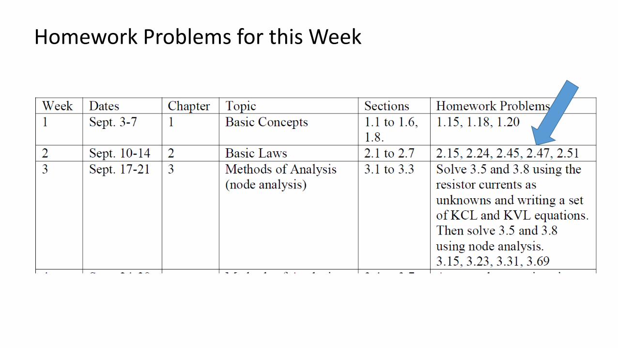
Homework Problems for this Week
Review: Series and Parallel Resistors
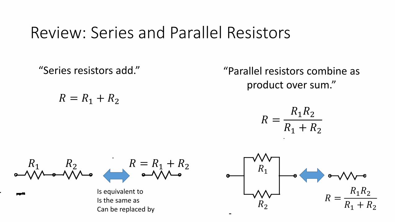
“Parallel resistors combine as product over sum.”
𝑅𝑅 =𝑅𝑅1𝑅𝑅2𝑅𝑅1 + 𝑅𝑅2
“Series resistors add.”
𝑅𝑅 = 𝑅𝑅1 + 𝑅𝑅2
𝑅𝑅1 𝑅𝑅2 𝑅𝑅 = 𝑅𝑅1 + 𝑅𝑅2
Is equivalent toIs the same asCan be replaced by
𝑅𝑅1
𝑅𝑅2𝑅𝑅 =
𝑅𝑅1𝑅𝑅2𝑅𝑅1 + 𝑅𝑅2
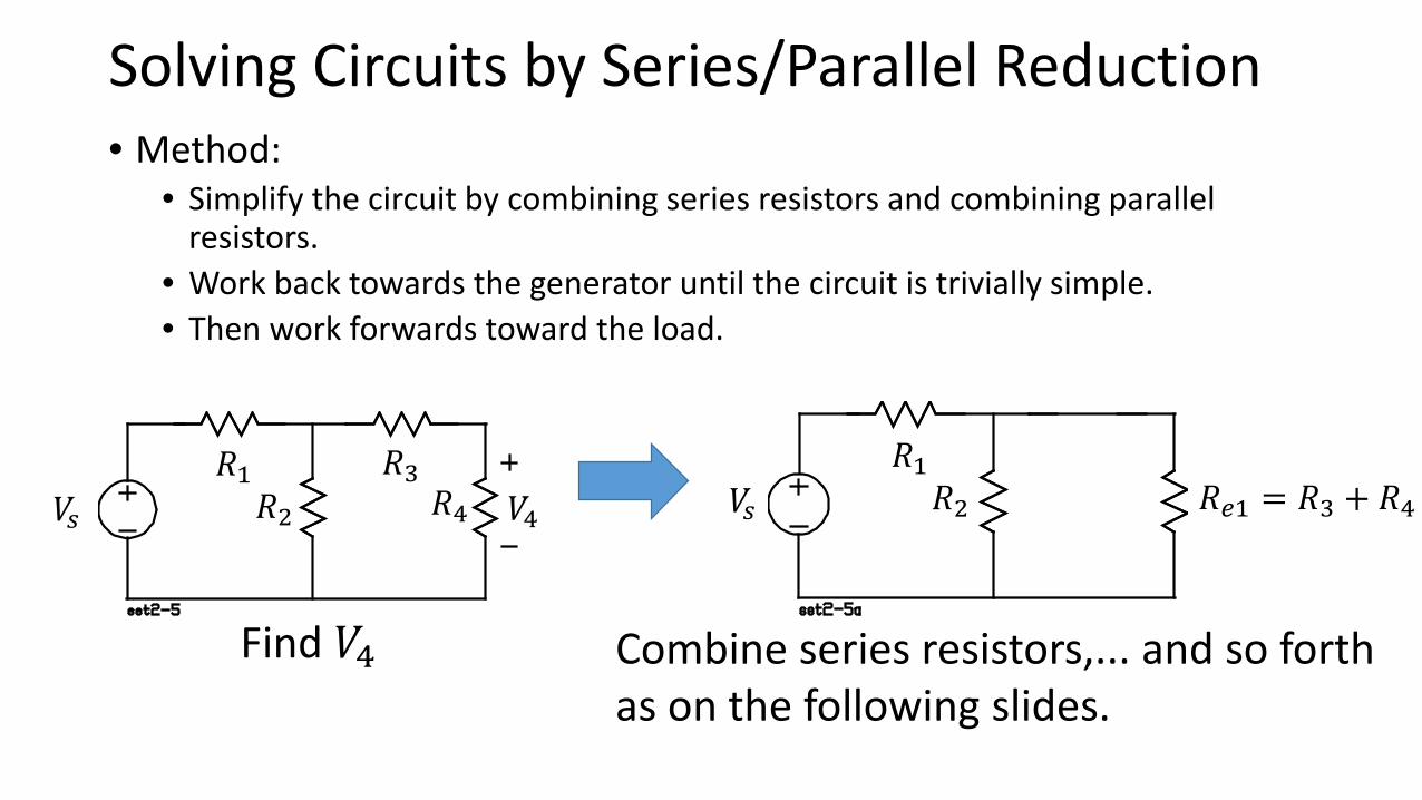
Solving Circuits by Series/Parallel Reduction• Method:
• Simplify the circuit by combining series resistors and combining parallel resistors.
• Work back towards the generator until the circuit is trivially simple.• Then work forwards toward the load.
Find 𝑉𝑉4 Combine series resistors,... and so forthas on the following slides.
𝑉𝑉𝑠𝑠 𝑉𝑉4𝑅𝑅1 𝑅𝑅3𝑅𝑅2 𝑅𝑅4 𝑉𝑉𝑠𝑠
𝑅𝑅1𝑅𝑅2 𝑅𝑅𝑒𝑒1 = 𝑅𝑅3 + 𝑅𝑅4
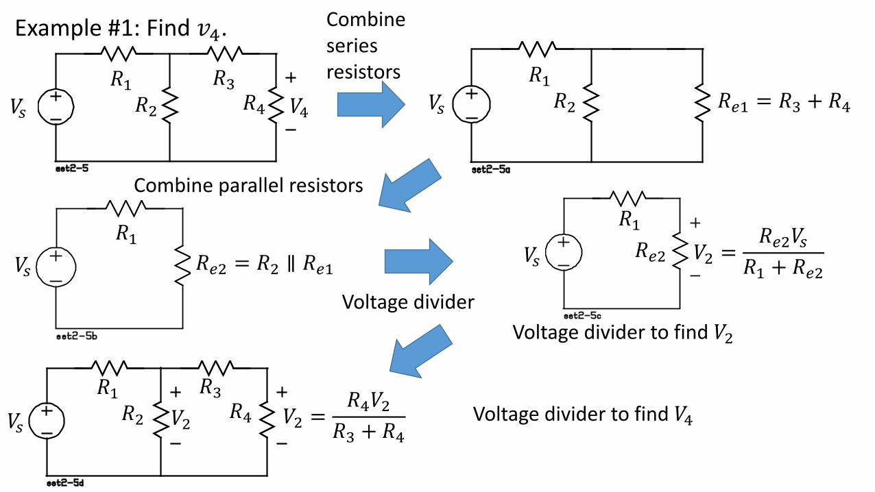
Combineseriesresistors
Combine parallel resistors
Voltage divider to find 𝑉𝑉2
Voltage divider to find 𝑉𝑉4
Voltage divider
Example #1: Find 𝑣𝑣4.
𝑉𝑉𝑠𝑠 𝑉𝑉4𝑅𝑅1 𝑅𝑅3𝑅𝑅2 𝑅𝑅4 𝑉𝑉𝑠𝑠
𝑅𝑅1𝑅𝑅2 𝑅𝑅𝑒𝑒1 = 𝑅𝑅3 + 𝑅𝑅4
𝑅𝑅1 𝑅𝑅3𝑅𝑅2 𝑅𝑅4
𝑉𝑉𝑠𝑠
𝑉𝑉𝑠𝑠
𝑉𝑉𝑠𝑠𝑅𝑅1
𝑅𝑅1
𝑅𝑅𝑒𝑒2 = 𝑅𝑅2 ∥ 𝑅𝑅𝑒𝑒1𝑅𝑅𝑒𝑒2 𝑉𝑉2 =
𝑅𝑅𝑒𝑒2𝑉𝑉𝑠𝑠𝑅𝑅1 + 𝑅𝑅𝑒𝑒2
𝑉𝑉2 𝑉𝑉2 =𝑅𝑅4𝑉𝑉2
𝑅𝑅3 + 𝑅𝑅4
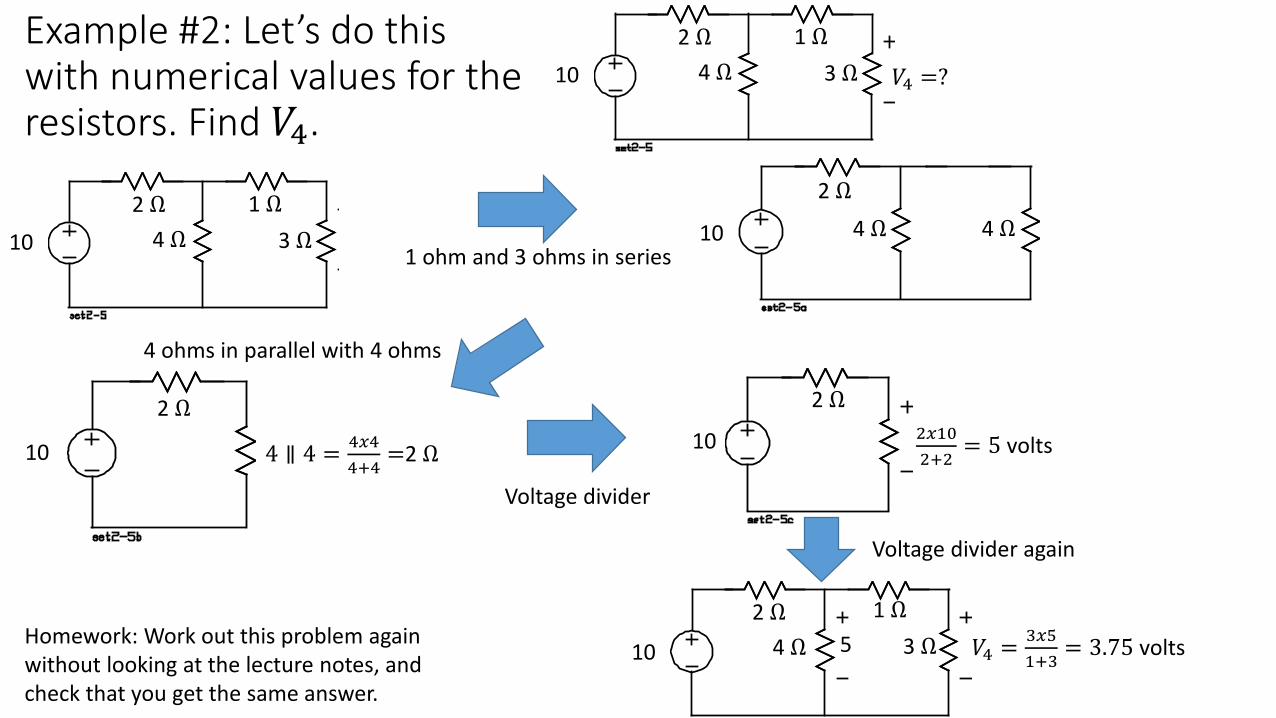
Example #2: Let’s do this with numerical values for the resistors. Find 𝑉𝑉4.
1 ohm and 3 ohms in series
4 ohms in parallel with 4 ohms
Voltage divider
Voltage divider again
Homework: Work out this problem again without looking at the lecture notes, and check that you get the same answer.
102 Ω
4 Ω1 Ω
3 Ω 𝑉𝑉4 =?
10
2 Ω4 Ω 4 Ω10
2 Ω4 Ω
1 Ω3 Ω
10
2 Ω
4 ∥ 4 = 4𝑥𝑥44+4
=2 Ω 10
2 Ω2𝑥𝑥1𝑥2+2
= 5 volts
10 52 Ω
4 Ω1 Ω
3 Ω 𝑉𝑉4 = 3𝑥𝑥𝑥1+3
= 3.75 volts
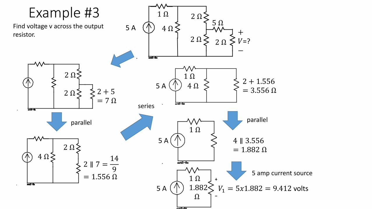
Example #3Find voltage v across the output resistor.
parallel
series
parallel
5 A
1 Ω
4 Ω2 Ω
2 Ω
5 Ω
2 Ω+𝑉𝑉=?−
2 Ω
2 Ω
2 + 5= 7 Ω
2 ∥ 7 =149
= 1.556 Ω
2 Ω4 Ω
2 + 1.556= 3.556 Ω5 A
1 Ω4 Ω
5 A1 Ω
4 ∥ 3.556= 1.882 Ω
5 amp current source
5 A1 Ω
𝑉𝑉1 = 5𝑥𝑥𝑥.882 = 9.412 volts1.882Ω
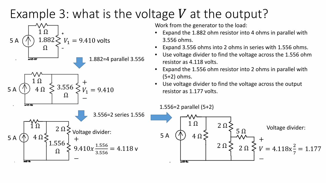
Example 3: what is the voltage 𝑉𝑉 at the output?Work from the generator to the load:• Expand the 1.882 ohm resistor into 4 ohms in parallel with
3.556 ohms.• Expand 3.556 ohms into 2 ohms in series with 1.556 ohms. • Use voltage divider to find the voltage across the 1.556 ohm
resistor as 4.118 volts.• Expand the 1.556 ohm resistor into 2 ohms in parallel with
(5+2) ohms.• Use voltage divider to find the voltage across the output
resistor as 1.177 volts.
5 A1 Ω
𝑉𝑉1 = 9.410 volts1.882Ω
3.556Ω
5 A1 Ω
4 Ω
1.556Ω
2 Ω4 Ω5 A
1 Ω
+𝑉𝑉1 = 9.410−
+9.4𝑥0𝑥𝑥 1.𝑥𝑥6
3.𝑥𝑥6= 4.118 v
−
Voltage divider: 5 A
1 Ω
4 Ω2 Ω
2 Ω
5 Ω
2 Ω+𝑉𝑉 = 4.118x 2
7= 1.177
−
Voltage divider:
1.882=4 parallel 3.556
1.556=2 parallel (5+2)3.556=2 series 1.556
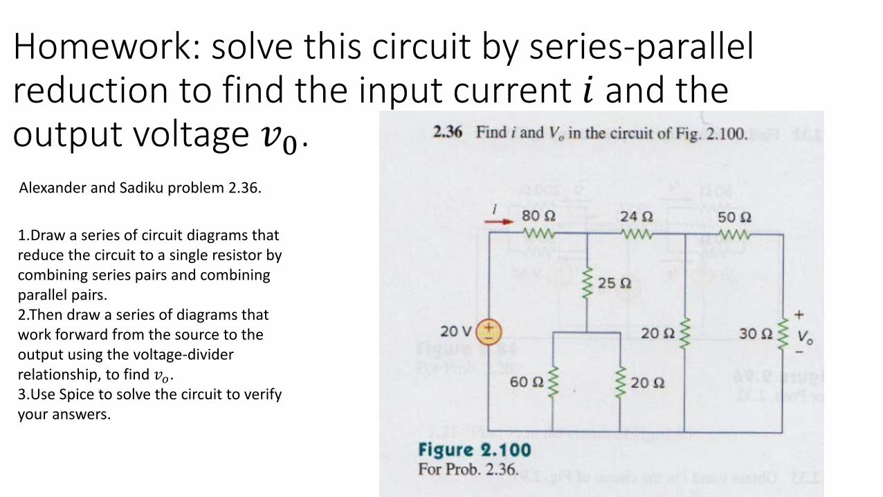
Homework: solve this circuit by series-parallel reduction to find the input current 𝑖𝑖 and the output voltage 𝑣𝑣𝑥. Alexander and Sadiku problem 2.36.
1.Draw a series of circuit diagrams that reduce the circuit to a single resistor by combining series pairs and combining parallel pairs.2.Then draw a series of diagrams that work forward from the source to the output using the voltage-divider relationship, to find 𝑣𝑣𝑜𝑜.3.Use Spice to solve the circuit to verify your answers.
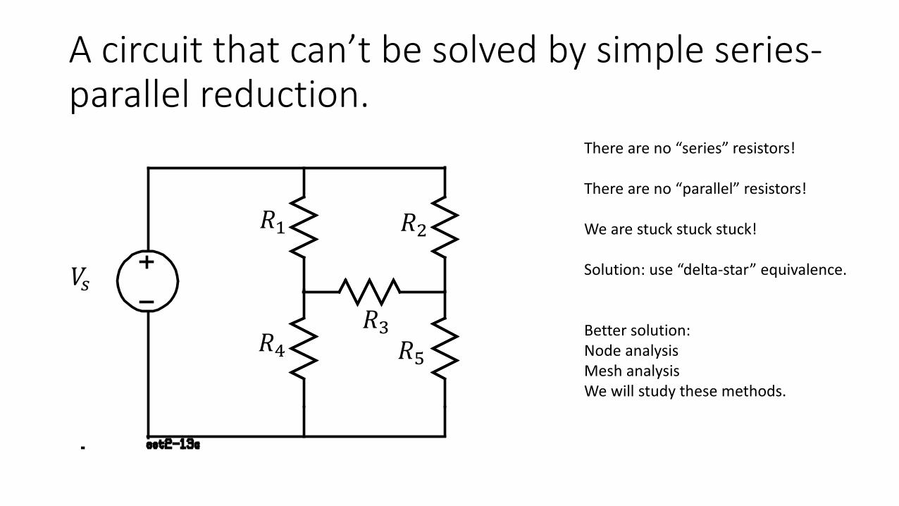
A circuit that can’t be solved by simple series-parallel reduction.
There are no “series” resistors!
There are no “parallel” resistors!
We are stuck stuck stuck!
Solution: use “delta-star” equivalence.
Better solution: Node analysisMesh analysisWe will study these methods.
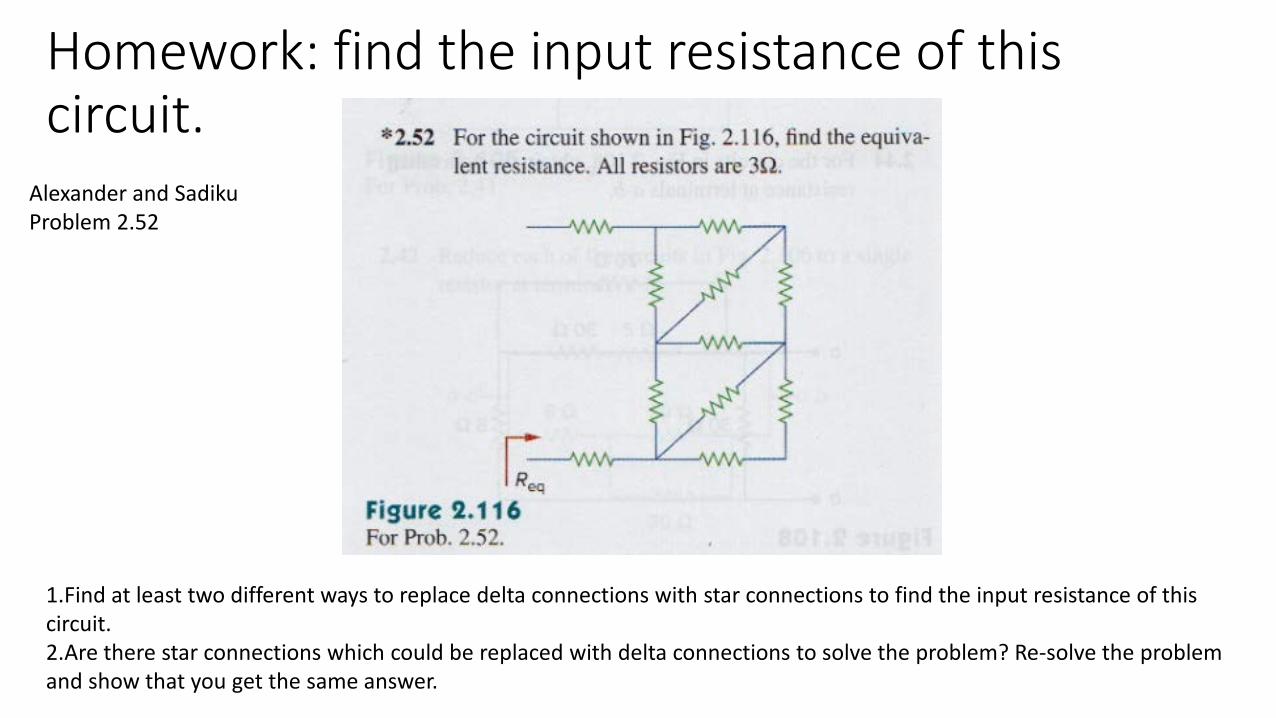
Homework: find the input resistance of this circuit.
Alexander and SadikuProblem 2.52
1.Find at least two different ways to replace delta connections with star connections to find the input resistance of this circuit. 2.Are there star connections which could be replaced with delta connections to solve the problem? Re-solve the problem and show that you get the same answer.
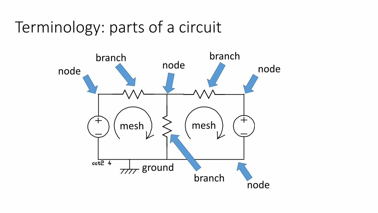
Terminology: parts of a circuit
mesh mesh
ground
branchnode
branch
branch
nodenode
node
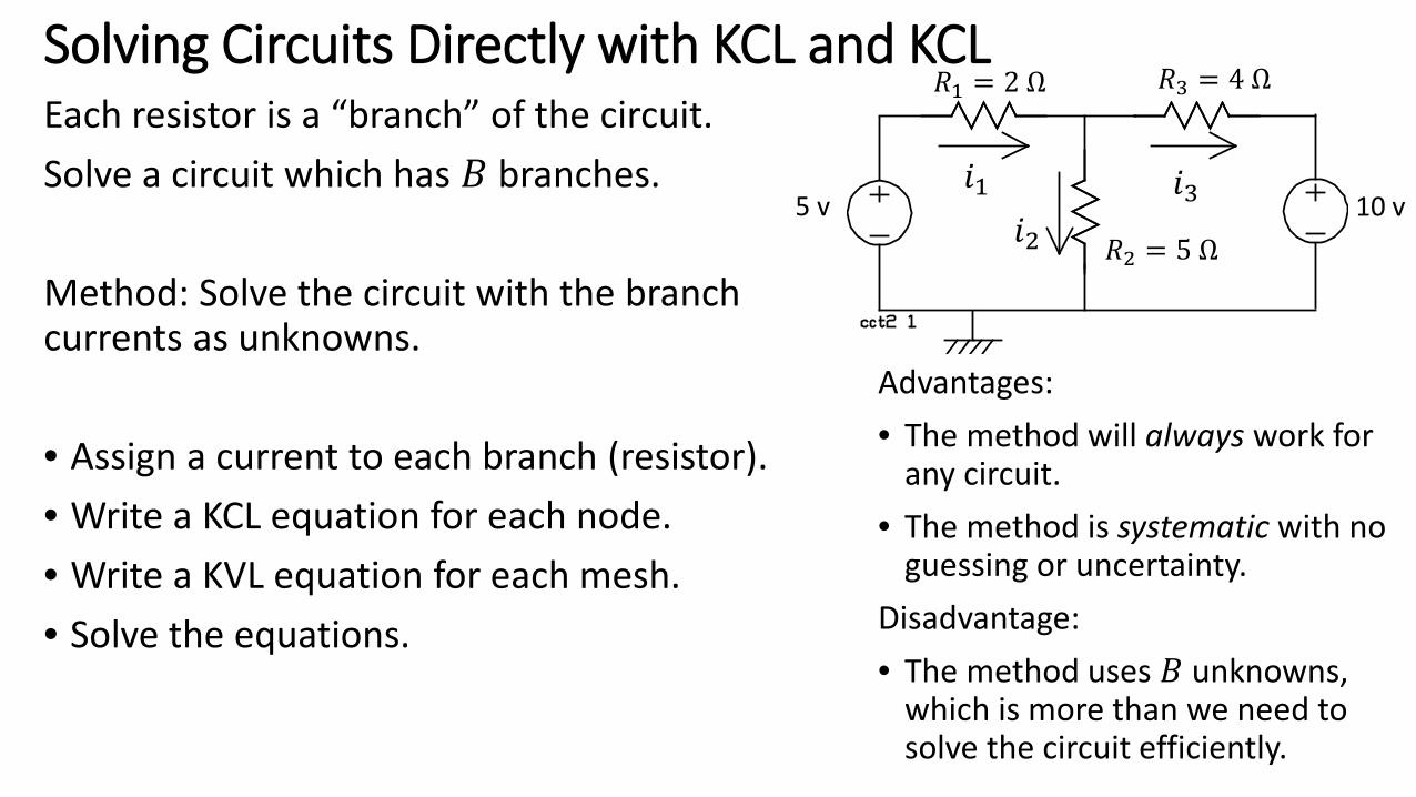
Solving Circuits Directly with KCL and KCLEach resistor is a “branch” of the circuit. Solve a circuit which has 𝐵𝐵 branches.
Method: Solve the circuit with the branch currents as unknowns.
• Assign a current to each branch (resistor).• Write a KCL equation for each node.• Write a KVL equation for each mesh.• Solve the equations.
Advantages:• The method will always work for
any circuit.• The method is systematic with no
guessing or uncertainty. Disadvantage: • The method uses 𝐵𝐵 unknowns,
which is more than we need to solve the circuit efficiently.
𝑅𝑅1 = 2 Ω 𝑅𝑅3 = 4 Ω
𝑅𝑅2 = 5 Ω5 v 10 v
𝑖𝑖1𝑖𝑖2
𝑖𝑖3
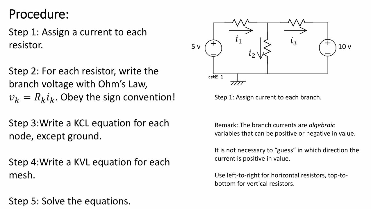
Procedure:Step 1: Assign a current to each resistor.
Step 2: For each resistor, write the branch voltage with Ohm’s Law, 𝑣𝑣𝑘𝑘 = 𝑅𝑅𝑘𝑘𝑖𝑖𝑘𝑘. Obey the sign convention!
Step 3:Write a KCL equation for each node, except ground.
Step 4:Write a KVL equation for each mesh.
Step 5: Solve the equations.
Step 1: Assign current to each branch.
5 v 10 v𝑖𝑖1
𝑖𝑖2𝑖𝑖3
Remark: The branch currents are algebraic variables that can be positive or negative in value.
It is not necessary to “guess” in which direction the current is positive in value.
Use left-to-right for horizontal resistors, top-to-bottom for vertical resistors.
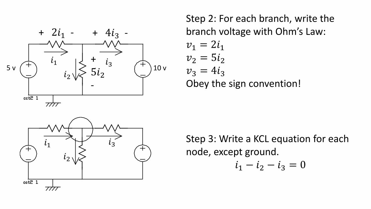
Step 3: Write a KCL equation for each node, except ground.
𝑖𝑖1 − 𝑖𝑖2 − 𝑖𝑖3 = 0
Step 2: For each branch, write the branch voltage with Ohm’s Law:𝑣𝑣1 = 2𝑖𝑖1𝑣𝑣2 = 5𝑖𝑖2𝑣𝑣3 = 4𝑖𝑖3Obey the sign convention!
5 v 10 v𝑖𝑖1
𝑖𝑖2𝑖𝑖3
+ 2𝑖𝑖1 - + 4𝑖𝑖3 -
+5𝑖𝑖2-
𝑖𝑖1𝑖𝑖2
𝑖𝑖3
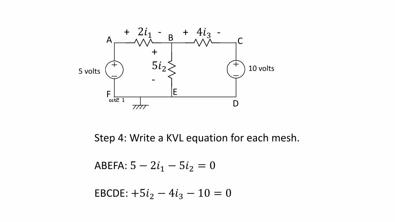
Step 4: Write a KVL equation for each mesh.
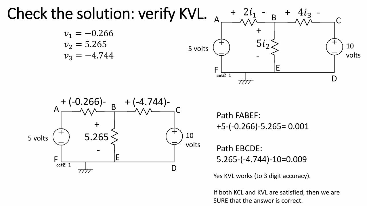
ABEFA: 5 − 𝑥𝑖𝑖1 − 5𝑖𝑖2 = 0
EBCDE: +5𝑖𝑖2 − 4𝑖𝑖3 − 10 = 0
5 volts 10 volts
+ 2𝑖𝑖1 - + 4𝑖𝑖3 -
+5𝑖𝑖2-
A B C
DEF
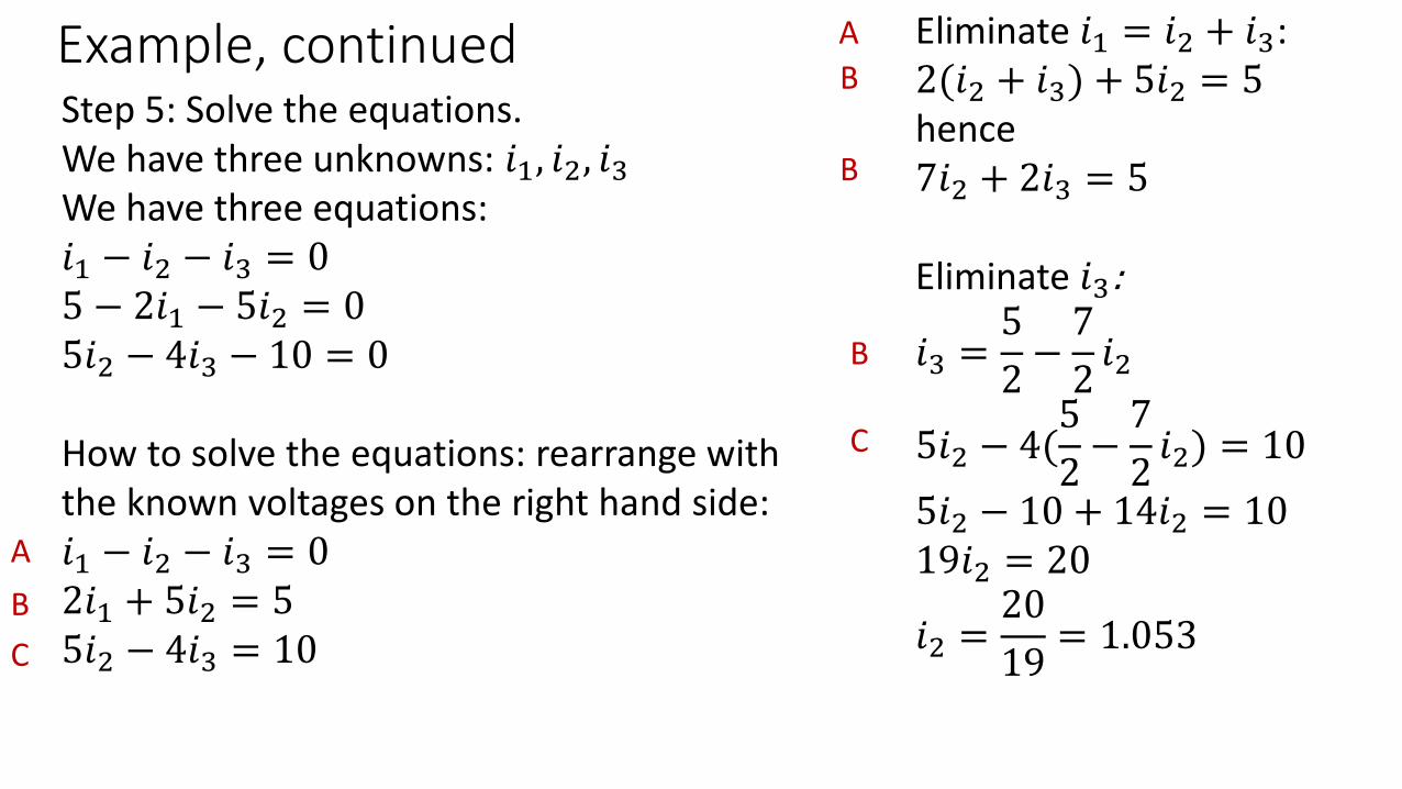
Example, continuedStep 5: Solve the equations.We have three unknowns: 𝑖𝑖1, 𝑖𝑖2, 𝑖𝑖3We have three equations:𝑖𝑖1 − 𝑖𝑖2 − 𝑖𝑖3 = 05 − 𝑥𝑖𝑖1 − 5𝑖𝑖2 = 05𝑖𝑖2 − 4𝑖𝑖3 − 10 = 0
How to solve the equations: rearrange with the known voltages on the right hand side: 𝑖𝑖1 − 𝑖𝑖2 − 𝑖𝑖3 = 02𝑖𝑖1 + 5𝑖𝑖2 = 55𝑖𝑖2 − 4𝑖𝑖3 = 10
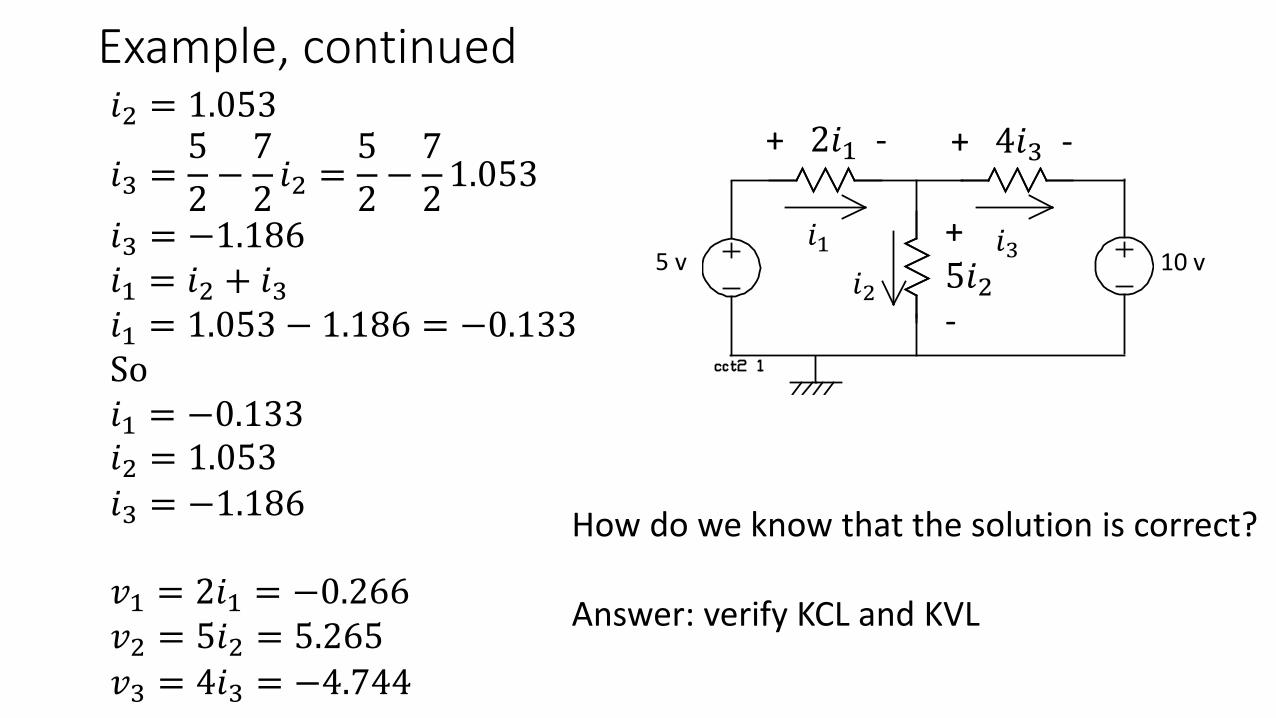
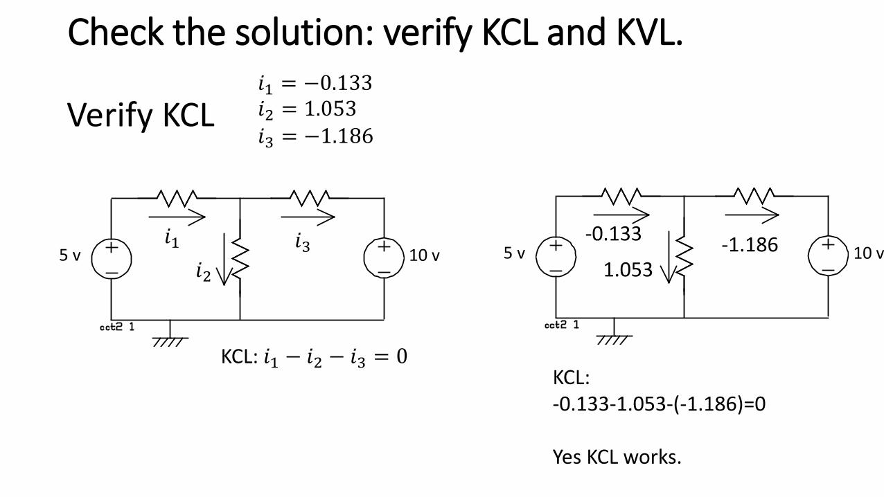
If both KCL and KVL are satisfied, then we are SURE that the answer is correct.
Introduction to SPICE SPICE = Simulation Program with Integrated Circuit Emphasis
• In ELEC273, you will use SPICE to solve the circuits in the laboratory and to compare with your measured data.
• There are many “free” versions of SPICE.• My preference is LTSpice:http://www.linear.com/designtools/software/• LTSpice is easy to learn and use and has all the features we need for this
course.• In later courses you will use Pspice, which is a full-featured ‘professional’
edition of Spice intended for integrated circuit design.
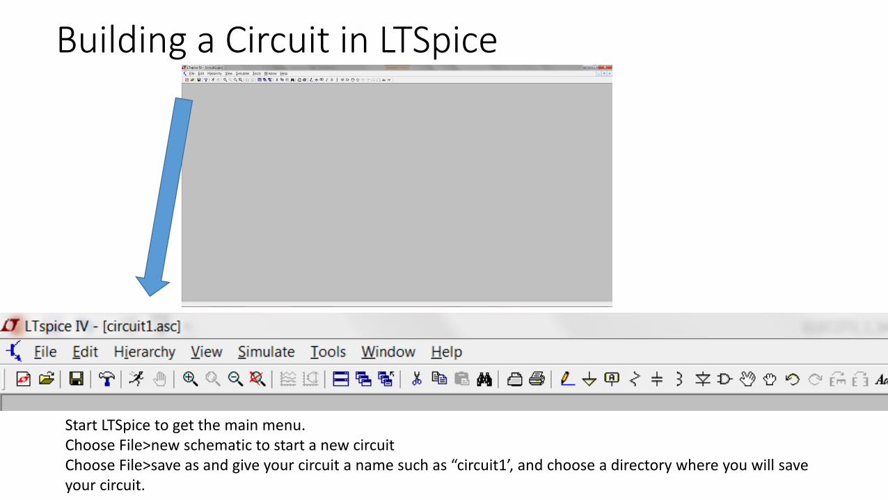
Start LTSpice to get the main menu.Choose File>new schematic to start a new circuitChoose File>save as and give your circuit a name such as “circuit1’, and choose a directory where you will save your circuit.
Add a Resistor
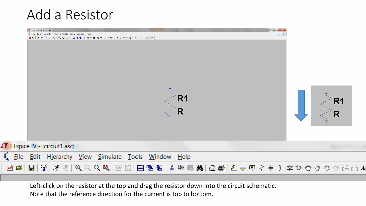
Left-click on the resistor at the top and drag the resistor down into the circuit schematic.Note that the reference direction for the current is top to bottom.
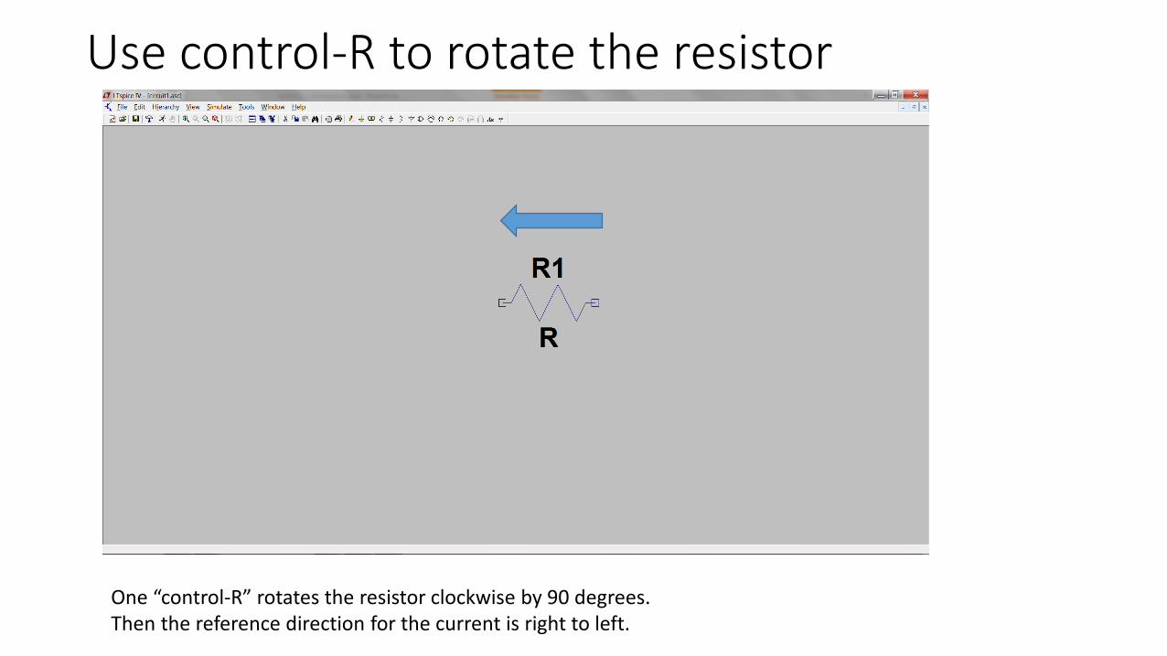
Use control-R to rotate the resistor
One “control-R” rotates the resistor clockwise by 90 degrees.Then the reference direction for the current is right to left.
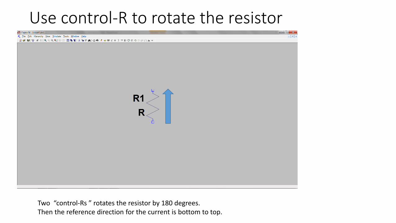
Use control-R to rotate the resistor
Two “control-Rs ” rotates the resistor by 180 degrees.Then the reference direction for the current is bottom to top.
Use control-R to rotate the resistor
Three “control-Rs” rotates the resistor clockwise by 270 degrees.So the reference direction for the current is left to right, which is usually what we want!
Add a voltage generator
Click the “components” symbol and type “vo” for “voltage” to get the voltage generator, then click OK
components
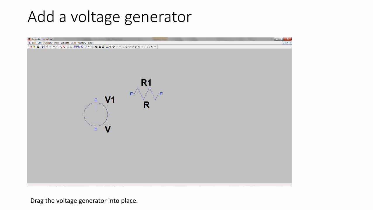
Add a voltage generator
Drag the voltage generator into place.
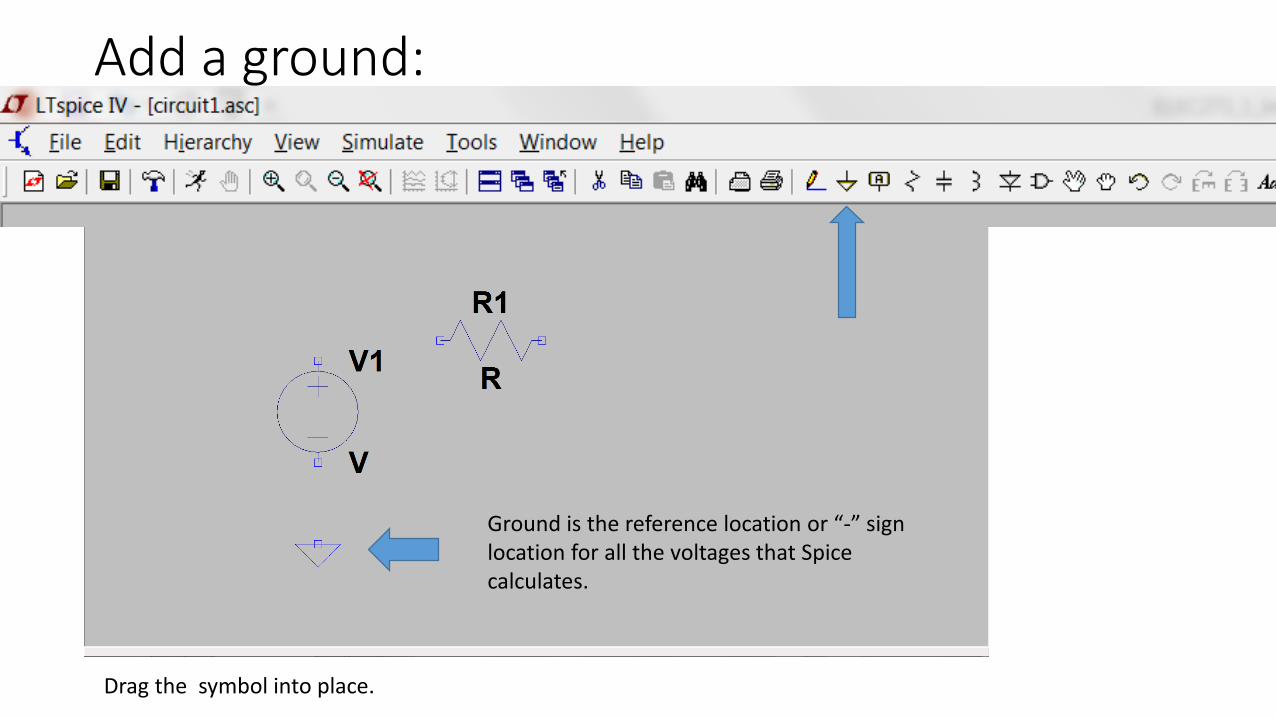
Add a ground:
Drag the symbol into place.
Ground is the reference location or “-” sign location for all the voltages that Spice calculates.
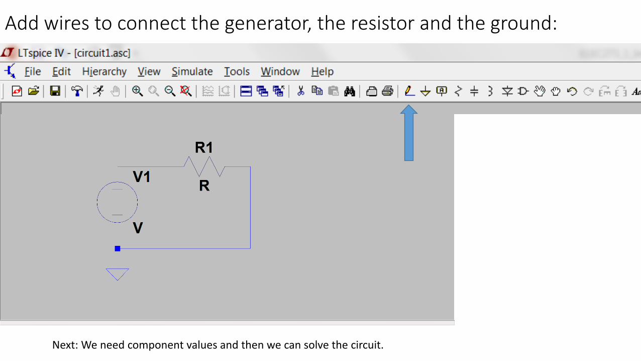
Add wires to connect the generator, the resistor and the ground:
Next: We need component values and then we can solve the circuit.
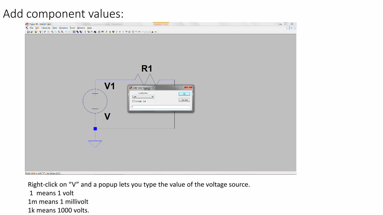
Add component values:
Right-click on “V” and a popup lets you type the value of the voltage source.1 means 1 volt
1m means 1 millivolt1k means 1000 volts.
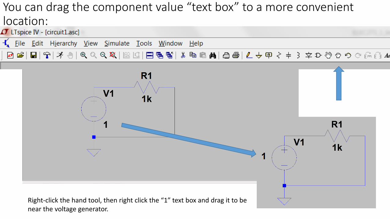
You can drag the component value “text box” to a more convenient location:
Right-click the hand tool, then right click the “1” text box and drag it to be near the voltage generator.
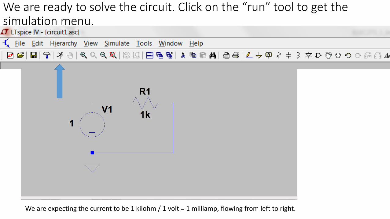
We are ready to solve the circuit. Click on the “run” tool to get the simulation menu.
We are expecting the current to be 1 kilohm / 1 volt = 1 milliamp, flowing from left to right.
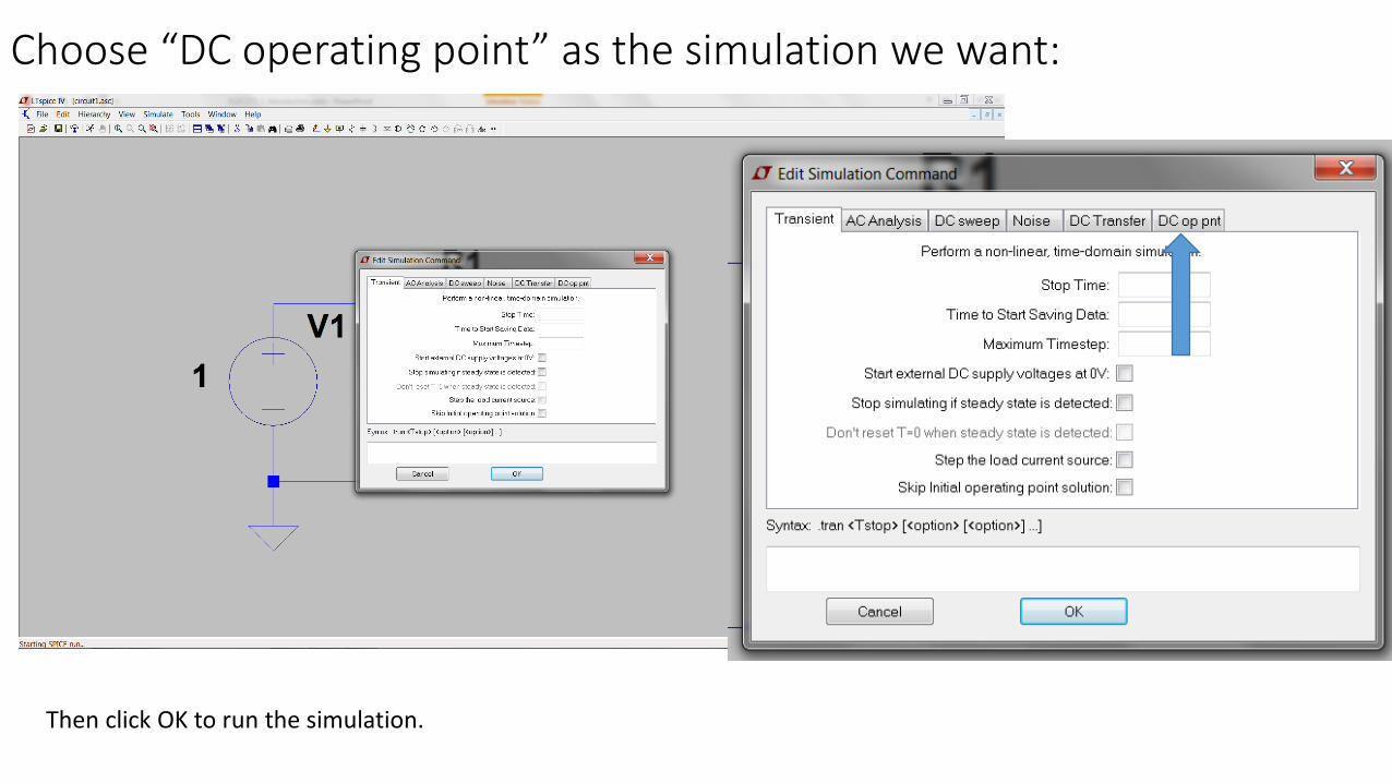
Choose “DC operating point” as the simulation we want:
Then click OK to run the simulation.
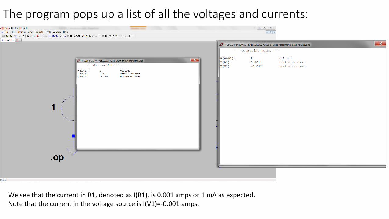
The program pops up a list of all the voltages and currents:
We see that the current in R1, denoted as I(R1), is 0.001 amps or 1 mA as expected.Note that the current in the voltage source is I(V1)=-0.001 amps.
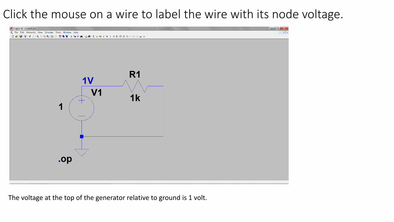
Click the mouse on a wire to label the wire with its node voltage.
The voltage at the top of the generator relative to ground is 1 volt.
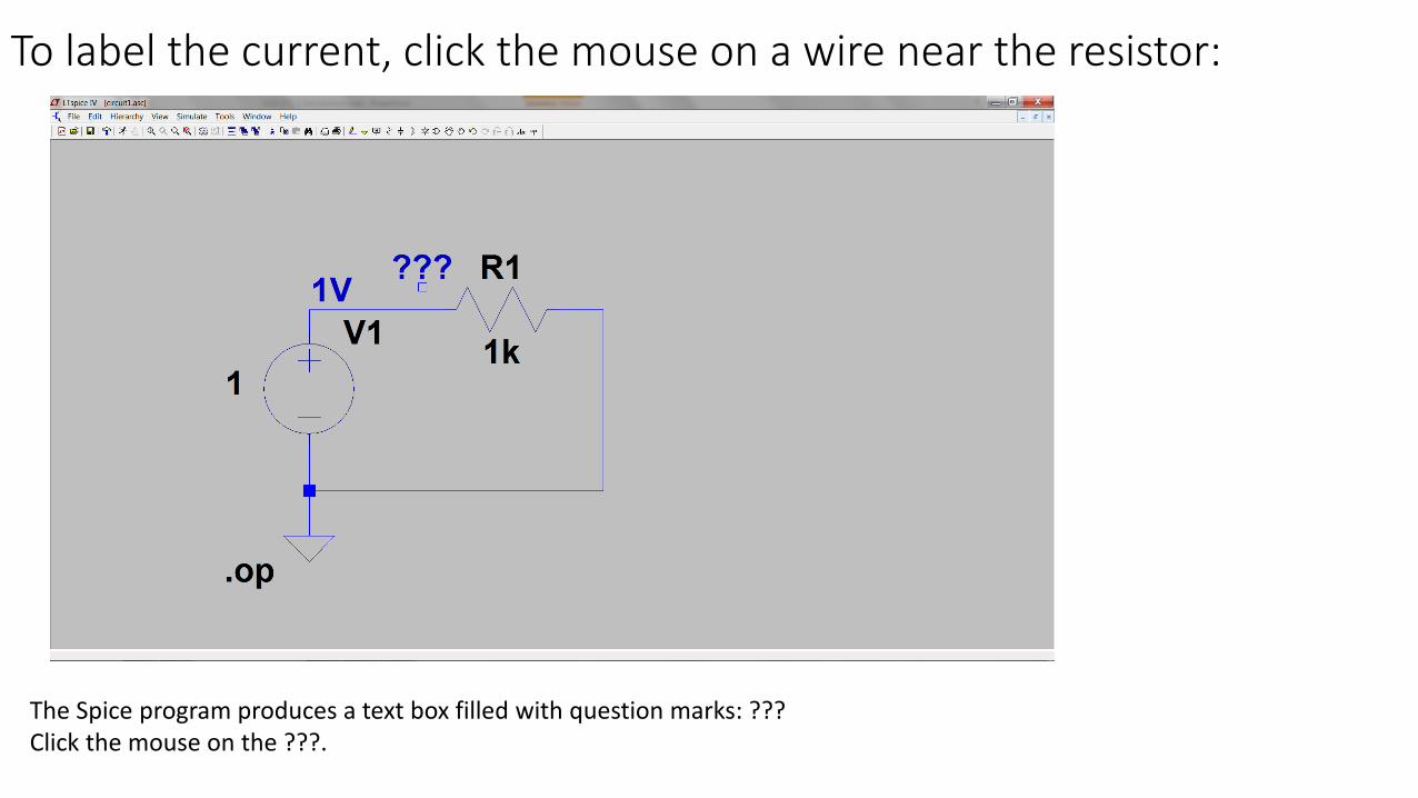
To label the current, click the mouse on a wire near the resistor:
The Spice program produces a text box filled with question marks: ???Click the mouse on the ???.
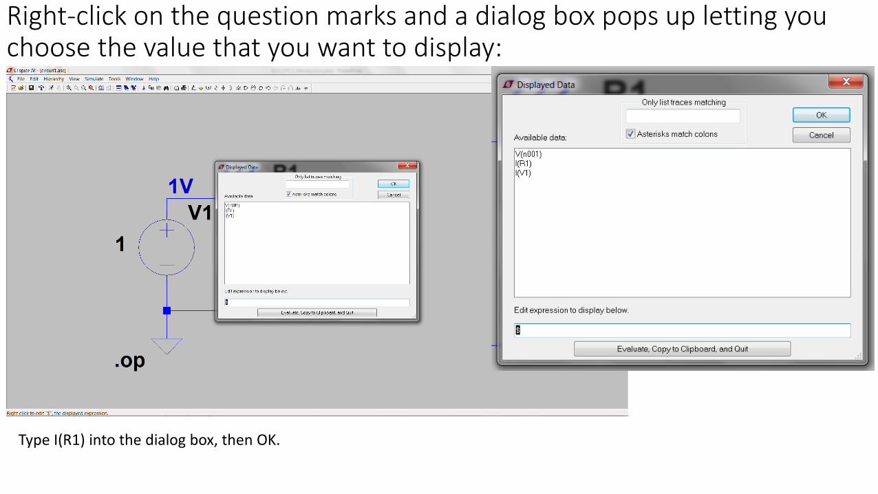
Right-click on the question marks and a dialog box pops up letting you choose the value that you want to display:
Type I(R1) into the dialog box, then OK.
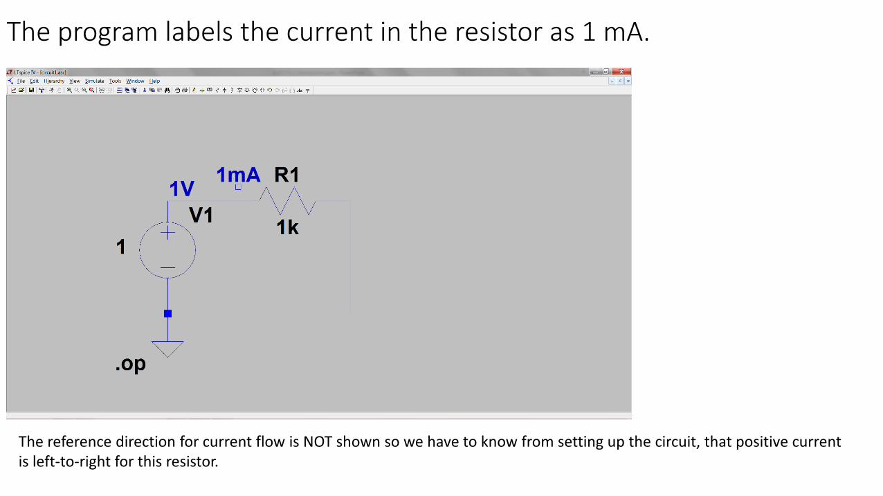
The program labels the current in the resistor as 1 mA.
The reference direction for current flow is NOT shown so we have to know from setting up the circuit, that positive current is left-to-right for this resistor.
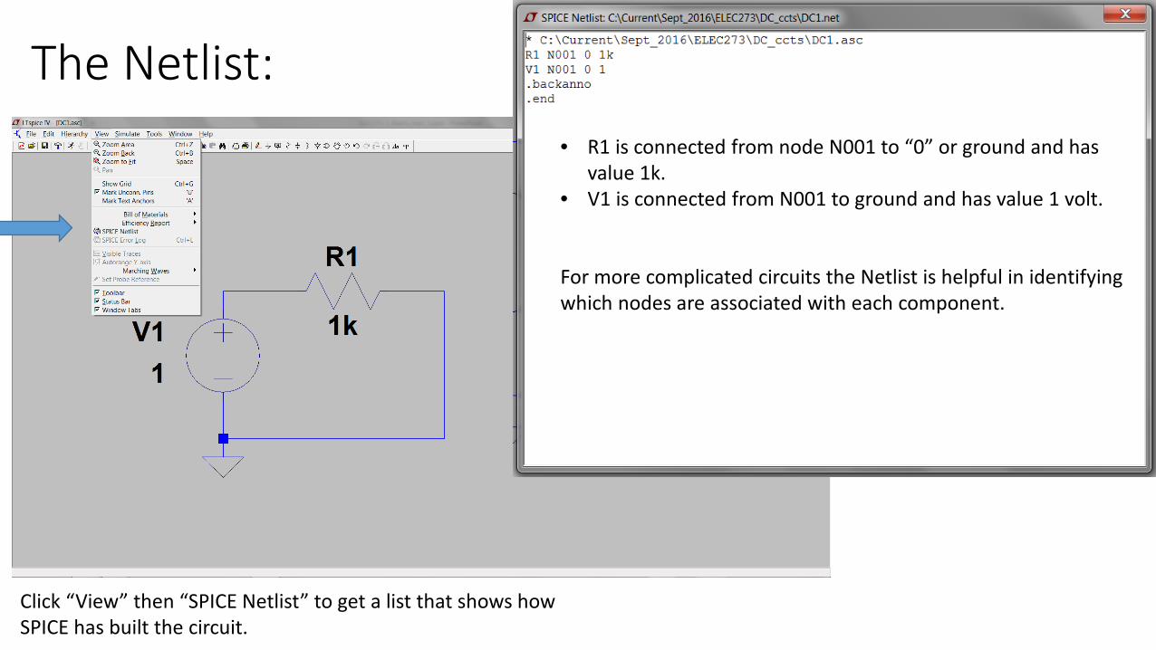
The Netlist:
Click “View” then “SPICE Netlist” to get a list that shows how SPICE has built the circuit.
• R1 is connected from node N001 to “0” or ground and has value 1k.
• V1 is connected from N001 to ground and has value 1 volt.
For more complicated circuits the Netlist is helpful in identifying which nodes are associated with each component.
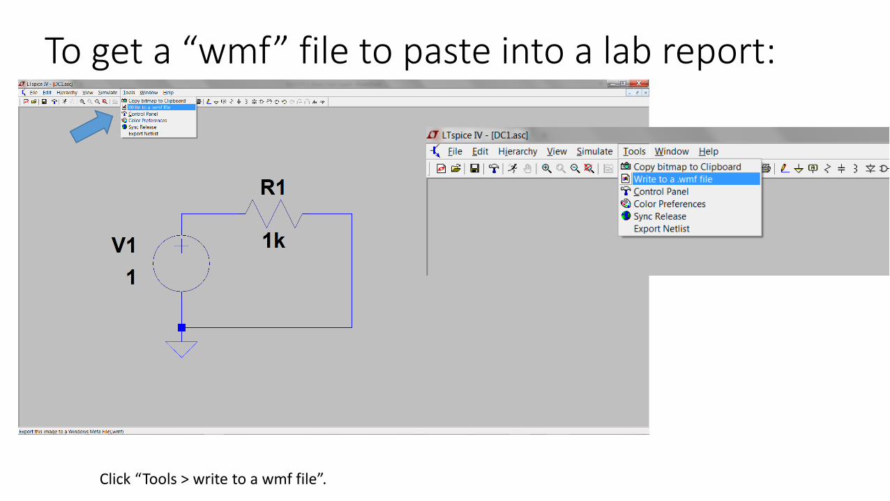
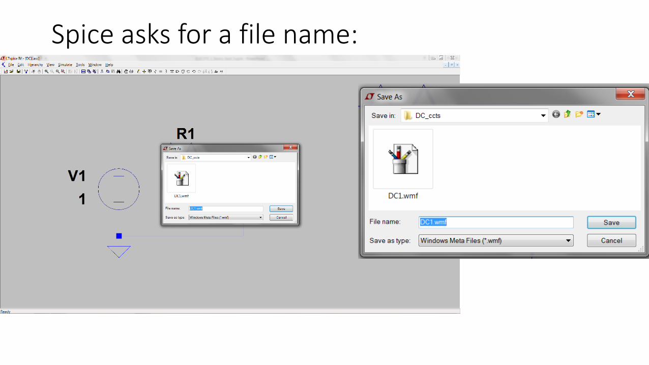
To get a “wmf” file to paste into a lab report:
Click “Tools > write to a wmf file”.
Spice asks for a file name:
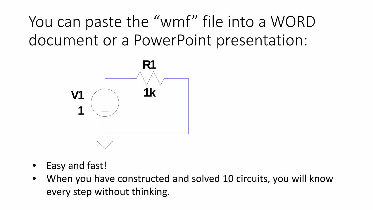
You can paste the “wmf” file into a WORD document or a PowerPoint presentation:
• Easy and fast!• When you have constructed and solved 10 circuits, you will know
every step without thinking.
R1
1kV11
Spice and ELEC273• You can solve the homework problems with Spice to check your
answers – fun!
• In one of the labs, you must use SPICE to simulation the circuits and compare the results with your measurements.
• In class we will frequently use LTSpice to solve circuits to check the answers that we find by analysis.
• In later courses you will use PSPICE to solve much more complex circuits.
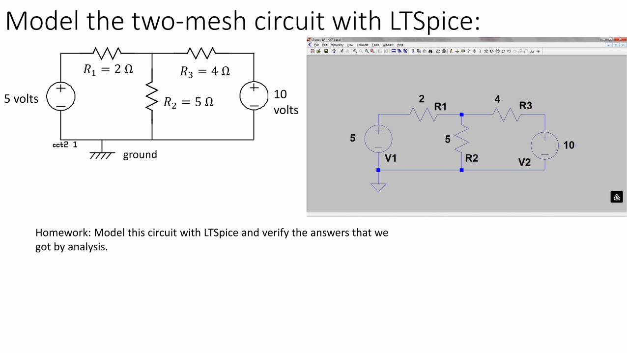
Model the two-mesh circuit with LTSpice:
5 volts 10 volts
𝑅𝑅1 = 2 Ω 𝑅𝑅3 = 4 Ω
𝑅𝑅2 = 5 Ω
ground
Homework: Model this circuit with LTSpice and verify the answers that we got by analysis.
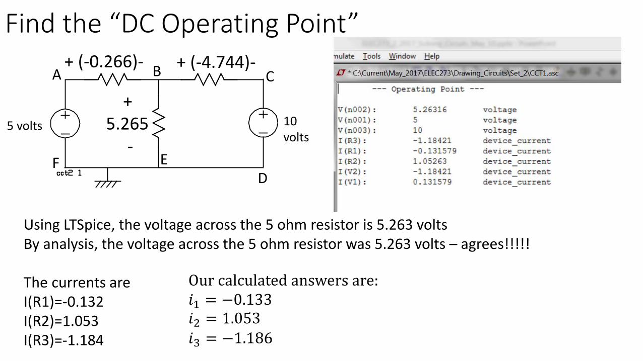
Find the “DC Operating Point”
Using LTSpice, the voltage across the 5 ohm resistor is 5.263 voltsBy analysis, the voltage across the 5 ohm resistor was 5.263 volts – agrees!!!!!
The currents areI(R1)=-0.132I(R2)=1.053I(R3)=-1.184
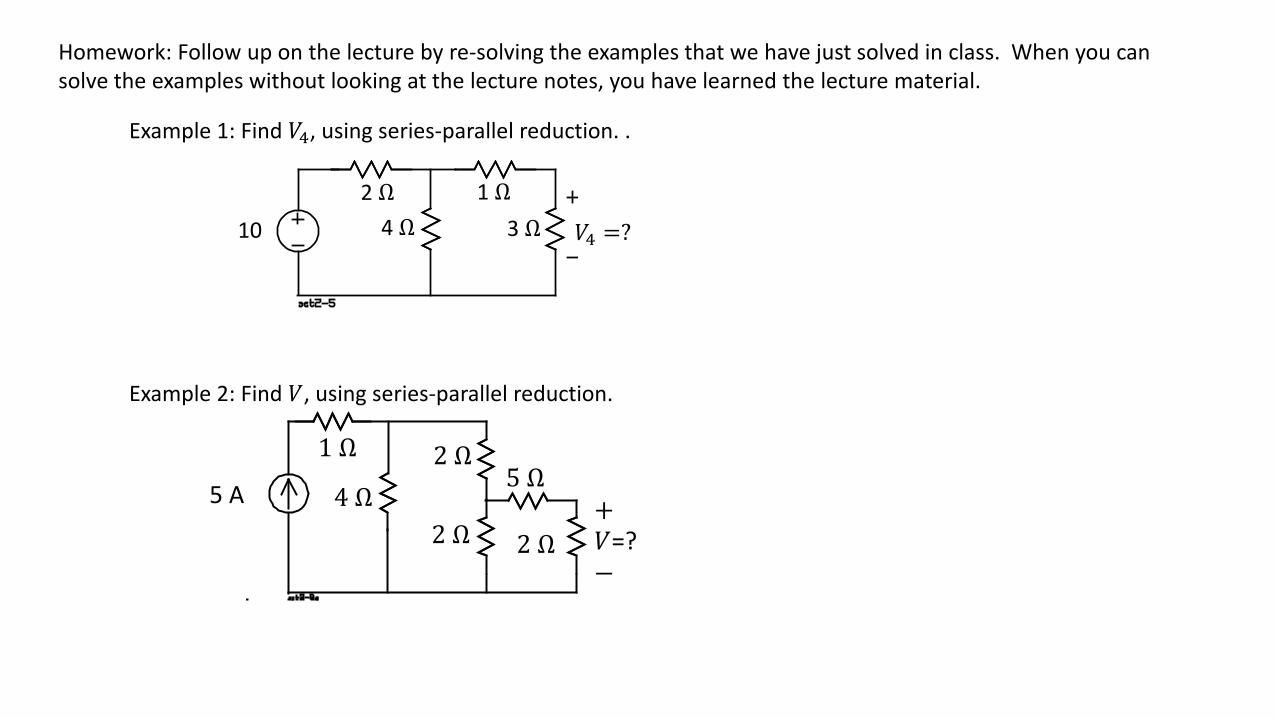
Example 1: Find 𝑉𝑉4, using series-parallel reduction. .
5 A
1 Ω
4 Ω2 Ω
2 Ω
5 Ω
2 Ω+𝑉𝑉=?−
Example 2: Find 𝑉𝑉, using series-parallel reduction.
Homework: Follow up on the lecture by re-solving the examples that we have just solved in class. When you can solve the examples without looking at the lecture notes, you have learned the lecture material.
𝑉𝑉𝑠𝑠𝑅𝑅1 𝑅𝑅2
𝑅𝑅4 𝑅𝑅𝑥
𝑅𝑅3
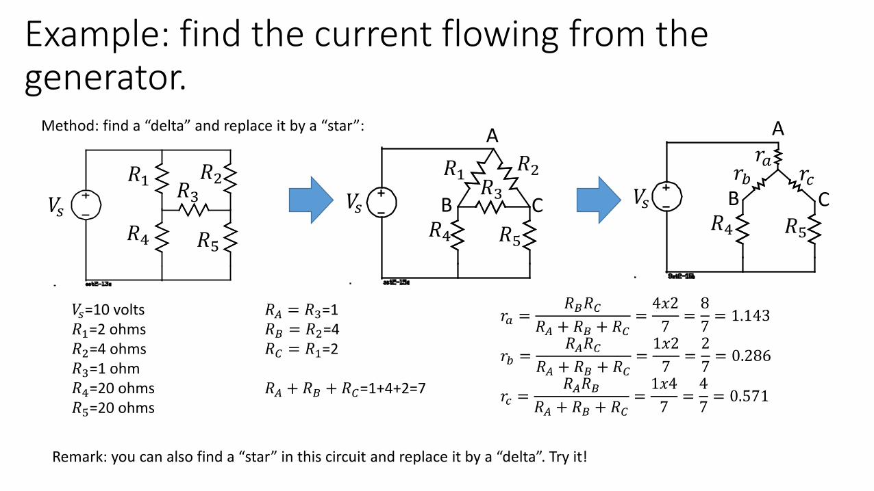
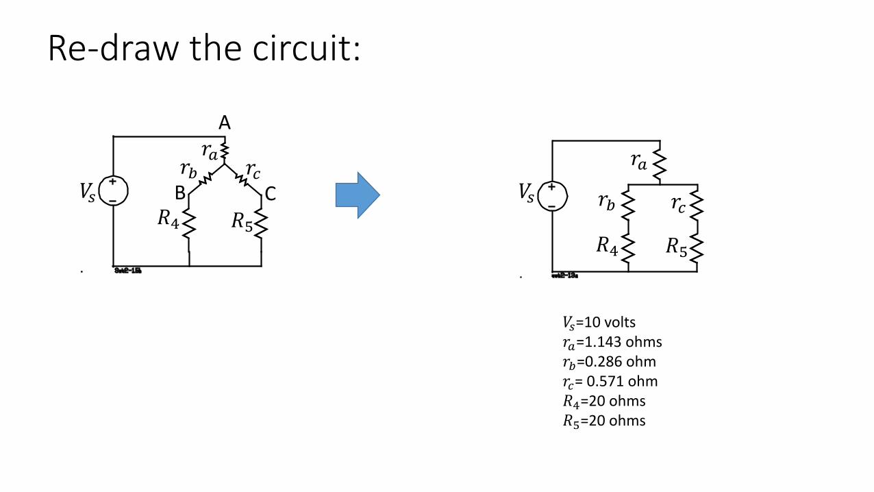
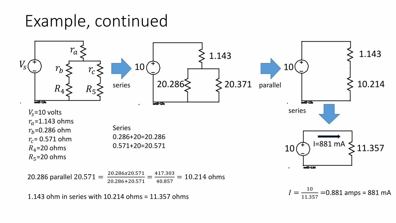
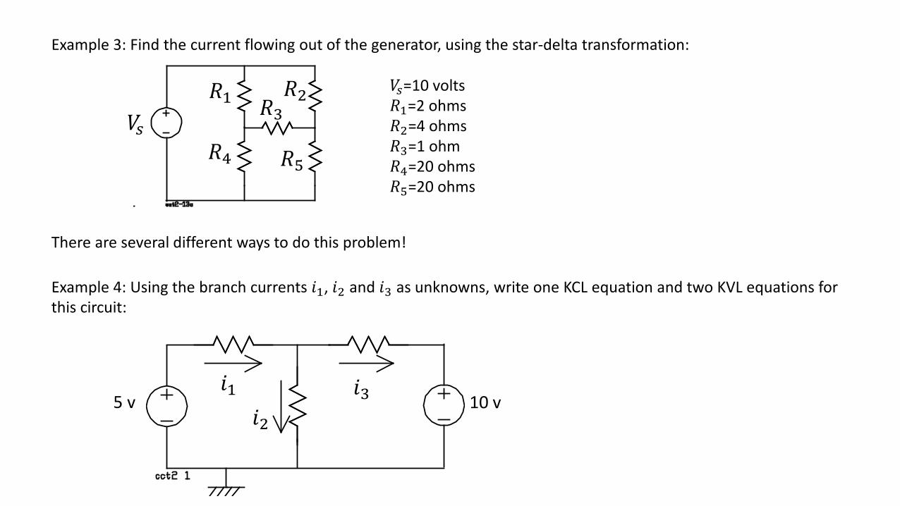
Example 3: Find the current flowing out of the generator, using the star-delta transformation:
There are several different ways to do this problem!
5 v 10 v𝑖𝑖1
𝑖𝑖2𝑖𝑖3
Example 4: Using the branch currents 𝑖𝑖1, 𝑖𝑖2 and 𝑖𝑖3 as unknowns, write one KCL equation and two KVL equations for this circuit:
Homework: solve this circuit by series-parallel reduction to find the input current 𝑖𝑖 and the output voltage 𝑣𝑣𝑥. Alexander and Sadiku problem 2.36.
1.Draw a series of circuit diagrams that reduce the circuit to a single resistor by combining series pairs and combining parallel pairs.2.Then draw a series of diagrams that work forward from the source to the output using the voltage-divider relationship, to find 𝑣𝑣𝑜𝑜.3.Use Spice to solve the circuit to verify your answers.
Homework: find the input resistance of this circuit.
Alexander and SadikuProblem 2.52
1.Find at least two different ways to replace delta connections with star connections to find the input resistance of this circuit. 2.Are there star connections which could be replaced with delta connections to solve the problem? Re-solve the problem and show that you get the same answer.
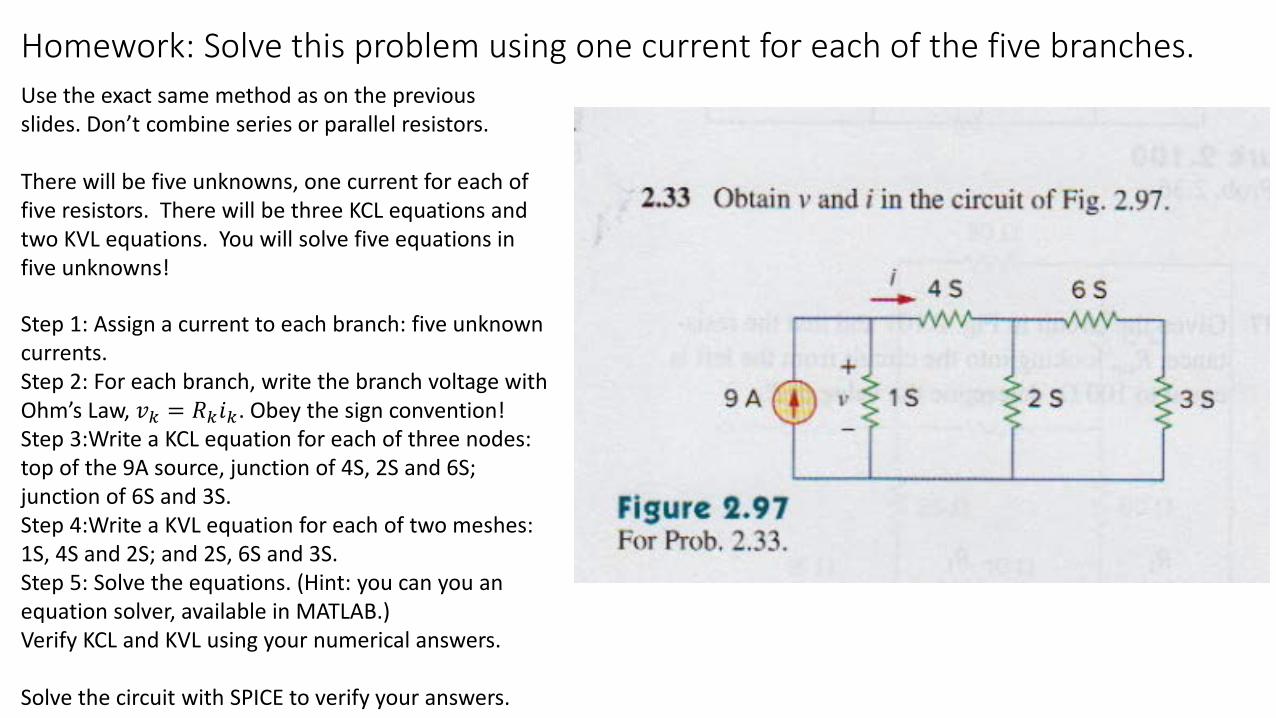
Homework: Solve this problem using one current for each of the five branches.
Step 1: Assign a current to each branch: five unknown currents.Step 2: For each branch, write the branch voltage with Ohm’s Law, 𝑣𝑣𝑘𝑘 = 𝑅𝑅𝑘𝑘𝑖𝑖𝑘𝑘. Obey the sign convention!Step 3:Write a KCL equation for each of three nodes: top of the 9A source, junction of 4S, 2S and 6S; junction of 6S and 3S. Step 4:Write a KVL equation for each of two meshes: 1S, 4S and 2S; and 2S, 6S and 3S. Step 5: Solve the equations. (Hint: you can you an equation solver, available in MATLAB.)Verify KCL and KVL using your numerical answers.
Solve the circuit with SPICE to verify your answers.
Use the exact same method as on the previous slides. Don’t combine series or parallel resistors.
There will be five unknowns, one current for each of five resistors. There will be three KCL equations and two KVL equations. You will solve five equations in five unknowns!