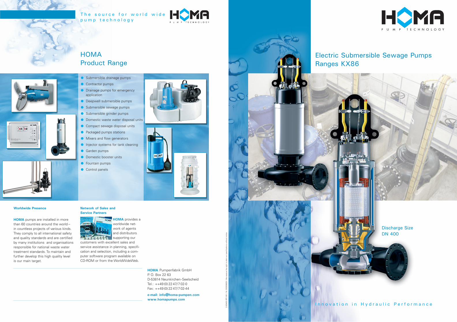
HOMA Product Range ● Submersible drainage pumps ● Contractor pumps ● Drainage pumps for emergency application ● Deepwell submersible pumps ● Submersible sewage pumps ● Submersible grinder pumps ● Domestic waste water disposal units ● Compact sewage disposal units ● Packaged pumps stations ● Mixers and flow generators ● Injector systems for tank cleaning ● Garden pumps ● Domestic booster units ● Fountain pumps ● Control panels The source for world wide pump technology HOMA Pumpenfabrik GmbH P. O. Box 22 63 D-53814 Neunkirchen-Seelscheid Tel.: ++49 (0) 22 47/7 02-0 Fax: ++49 (0) 22 47/ 7 02-44 e-mail: [email protected]www.homapumps.com Worldwide Presence HOMA pumps are installed in more than 60 countries around the world – in countless projects of various kinds. They comply to all international safety and quality standards and are certified by many institutions and organisations responsible for national waste water treatment standards. To maintain and further develop this high quality level is our main target. HOMA provides a worldwide net- work of agents and distributors supporting our customers with excellent sales and service assistance in planning, specifi- cation and selection, including a com- puter software program available on CD-ROM or from the WorldWideWeb. Network of Sales and Service Partners Discharge Size DN 400 3.0/0405 (RP) 001 / Nr. 0033080EN We reserve the right to alter our specifications without notice. Innovation in Hydraulic Performance Electric Submersible Sewage Pumps Ranges KX86
HOMA pumps are installed in morethan 60 countries around the world –in countless projects of various kinds.They comply to all international safetyand quality standards and are certifiedby many institutions and organisationsresponsible for national waste watertreatment standards. To maintain andfurther develop this high quality levelis our main target.
HOMA provides aworldwide net-work of agentsand distributorssupporting our
customers with excellent sales andservice assistance in planning, specifi-cation and selection, including a com-puter software program available onCD-ROM or from the WorldWideWeb.
Network of Sales and
Service Partners
Discharge Size
DN 400
3.0/
0405
(RP
) 001
/ N
r. 00
3308
0EN
We
rese
rve
the
right
to
alte
r ou
r sp
ecifi
catio
ns w
ithou
t no
tice.
I n n o v a t i o n i n H y d r a u l i c P e r f o r m a n c e
Electric Submersible Sewage Pumps
Ranges KX86
32
T h e s o u r c e f o r h i g h e f f i c i e n c y
High Performance
in Waste Water Pumping
HOMA submersible waste water andsewage pumps operate worldwide innumerous kinds of domestic, municipaland industrial applications. Decades ofexperience in the design and manufac-turing of submersible pumps plusuncompromising attention to quality inevery detail and strict monitoring ofproduction quality ensure the utmostreliability and long service life of allHOMA products.
Flexible system-components
for problem-free installation
HOMA combines efficiency, safety, highquality and robust design with a flexibili-ty that allows the individual optimizationof every project realization:
The reliability of fully
automatic operation
HOMA waste water pumping stationsfeature fully automatic control and moni-toring. Reliable liquid level control sys-tems of various types (float switch,pneumatic, ultrasound or electronic sys-tems) are available to secure reliablepump operation at minimum energyconsumption. All possible fault factorslike shaft seal condition, temperatures,moisture or power supply can be auto-matically monitored and transferred tovarious alarm systems.
Pumps for various types of applicationand installation, a complete program ofinstallation equipment including pipes,valves, pump pits from concrete orcomposite materials, electric controland monitoring systems. With thisrange HOMA can provide a tailor -madesolution for every waste water pump-ing application.
54
The right installation for every pump station Operating conditions
The motors are designed for continu-ous operating duty (S1) at maximum15 starts per hour. In addition to a fullysubmerged motor housing in wet wellinstallation, a jacket cooled motor-vari-ant is available for S1 operating with anon-fully submerged motor or for drywell installation.
Pumps with enclosed two-channelimpellers are designed for intermittentoperation, normally in automatic level-controlled wet or dry well sumpinstallations. They are also suitable forlimited continuous operation, as instorm water retention tanks, or forunlimited continuous operation, suchas industrial water supply.
T h e s o u r c e f o r e x t r a o p t i o n s a n d a p p l i c a t i o n s
Various challenges – individual solutions:HOMA submersible wastewater pumpsare designed for pumping sewage,sludge, effluents or surface water,including liquids containing a large pro-portion of solid or fibrous matter. They areinstalled in domestic, municipal, industrialand agricultural pumping applications.
For chemically aggressive liquids, specificcomponents like impellers, volutes orcomplete units are also available fromhigh-resistant materials like stainlesssteel, duplex or bronze.
Wet well installation with base stand
Submerged pump mountedon a ring base stand fortemporary, service oremergency operation.Discharge connectionwith pipe or hose.
Higher Performance
to meet every Challenge
Ranges and Models
All motors are also suitable for operatingwith frequency converter or soft starterdevice.
Explosion protection:
In addition to the standard version, allmotors are available explosion proofaccording to ATEX Ex II 2 G EEXd.
Dry well variant:
Besides the version for submerged ope-ration, all pumps are also available fordry well or non-submerged operation.Motor cooling is provided by a coolingjacket, using either the pumped liquid orexternal coolant circulation.
Hydraulic selection
Discharge and suction flange:
● DN 200● DN 250● DN 300● DN 400
Reducing adapters for different auto-coupling system and valve dimensionsare available.
Motor selection
Motor speed:
For the standard hydraulic ranges, themotors are designed with the followingspeeds:
● 1450 U/min = 4-pole
● 960 U/min = 6-pole
● 720 U/min = 8-pole
Voltages:
All specified data relate to an operatingvoltage of 400 V/3 Ph, 50 Hz. Differentvoltages are available on request.
Type of starting:
The motors are supplied as standardsuitable for Direct- or Star-Delta-Start.
Motor monitoring:
All motors are supplied with temperaturesensors in the winding, bi-metalic sen-sors (standard) or PTC sensors or PT 100(on request).● Motors for wet well installation
(without cooling jacket):As C-version (see pump type code) with oil chamber seal condition monitoring probe and moisture sensor in junction chamber)
● Motors with cooling jacket:Supplied as standard with oil chamber seal condition monitoring probe.
S-version additionally with moisture monitoring in the stator housing.Additional monitoring devices (e. g. bear-ing temperature) on request.
Submerged autocoupling guide tubesystem for automatic connection anddisconnection of the pump from thepipework from outside the sump. Allmaintenance or repair work can be doneoutside the sump. Back in operatingposition, the weight of the pump ensu-res leak-proof discharge connection.
Impeller spherical clearance:
The pumps are available with impellerspherical clearances from 100 mm to165 mm according to pump range.
Enclosed two channel impeller
For liquids containing impuritiesand sludge with solid particles.
Pump type code:
Impeller
design:
Discharge
size:
Spherical
clearance:
Impeller
diameter:
Motor frame
size:
Jacket
cooled:
only for
motors
without
jacket
cooling
Moisture
monitor-
ing in the
stator
housing
Motor power
(coded)Speed: Explosion
proof motor
▲ ▲ ▲ ▲ ▲ ▲ ▲ ▲ ▲ ▲
K(X) 4 4 80 - H (U) 26 4 (C) (S) (EX)MotorPump
K, KX =
Enclosed twochannel
4 = 200 mm5 = 250 mm6 = 300 mm8 = 400 mm
4 = 100 mm5 = 130 mm6 = 150 mm
165 mm
(mm : 5)
e. g.
80 = 100 mm
F, G,
H, R
Jacket cooled
motor for non-
submerged
installation
4 = 4 pole
(1450 rpm)6 = 6 pole
(960 rpm)8 = 8 pole
(720 rpm)
▲
1
2
4
▲
▲
8 ▲
6 ▲
14 ▲
13 ▲
10 ▲
14 ▲
10▲
▲
11
▲
12
▲
5
▲
9 ▲
7
▲
9
▲
Discharge
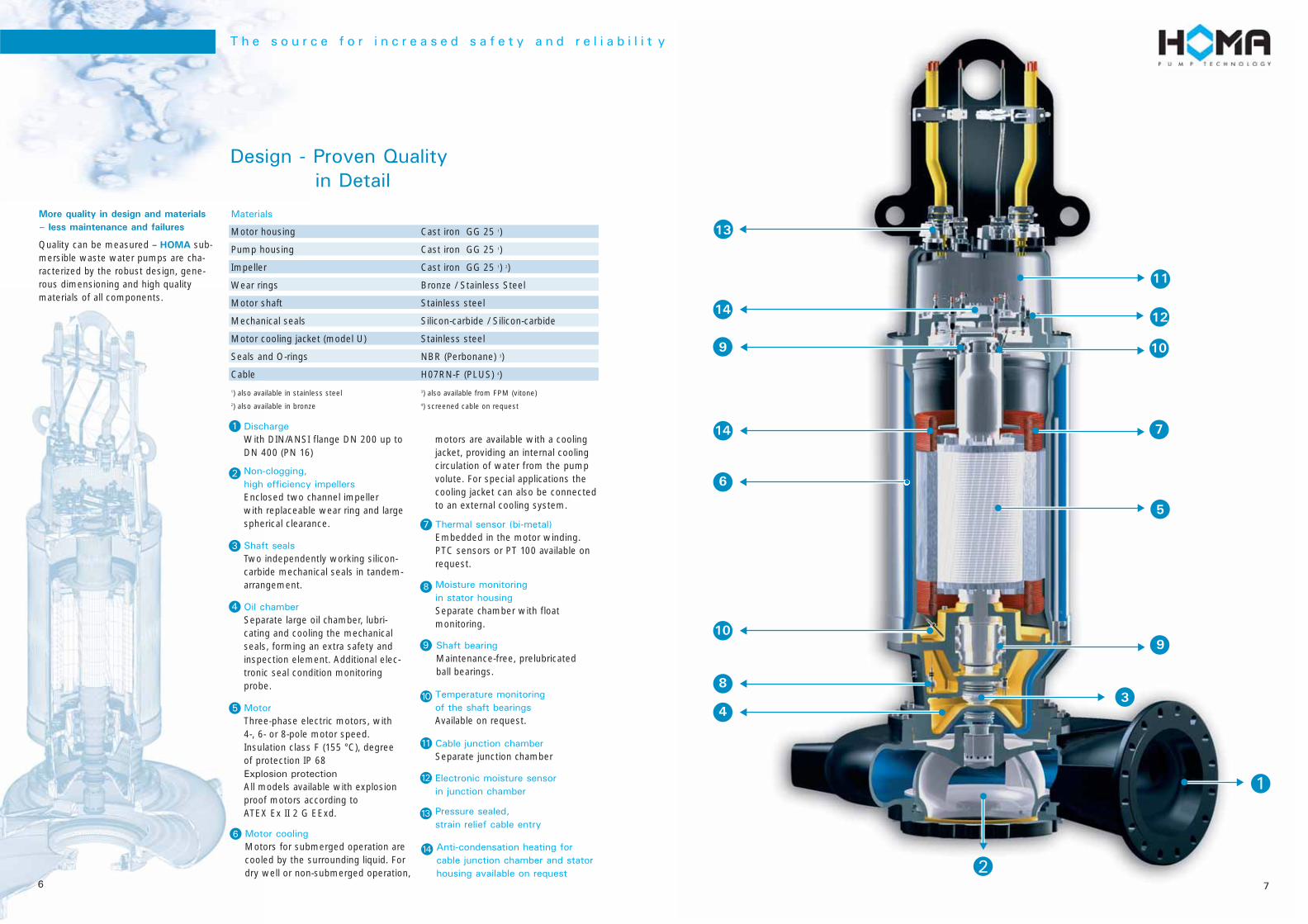
With DIN/ANSI flange DN 200 up toDN 400 (PN 16)
76
Design - Proven Quality
in Detail
More quality in design and materials
– less maintenance and failures
Quality can be measured – HOMA sub-mersible waste water pumps are cha-racterized by the robust design, gene-rous dimensioning and high qualitymaterials of all components.
Shaft seals
Two independently working silicon-carbide mechanical seals in tandem-arrangement.
Motor cooling
Motors for submerged operation arecooled by the surrounding liquid. Fordry well or non-submerged operation,
Moisture monitoring
in stator housing
Separate chamber with floatmonitoring.
T h e s o u r c e f o r i n c r e a s e d s a f e t y a n d r e l i a b i l i t y
1) also available in stainless steel 3) also available from FPM (vitone)2) also available in bronze 4) screened cable on request
Electronic moisture sensor
in junction chamber
Temperature monitoring
of the shaft bearings
Available on request.
Shaft bearing
Maintenance-free, prelubricatedball bearings.
Motor
Three-phase electric motors, with4-, 6- or 8-pole motor speed.Insulation class F (155 °C), degreeof protection IP 68Explosion protection
All models available with explosionproof motors according toATEX Ex II 2 G EExd.
Thermal sensor (bi-metal)
Embedded in the motor winding.PTC sensors or PT 100 available onrequest.
Non-clogging,
high efficiency impellers
Enclosed two channel impeller with replaceable wear ring and largespherical clearance.
Cable junction chamber
Separate junction chamber
Oil chamber
Separate large oil chamber, lubri-cating and cooling the mechanicalseals, forming an extra safety andinspection element. Additional elec-tronic seal condition monitoringprobe.
3
1
2
4
9
5
7
10
11
12
Pressure sealed,
strain relief cable entry
13
Anti-condensation heating for
cable junction chamber and stator
housing available on request
14
8
6
motors are available with a coolingjacket, providing an internal coolingcirculation of water from the pumpvolute. For special applications thecooling jacket can also be connectedto an external cooling system.
3
▲
8
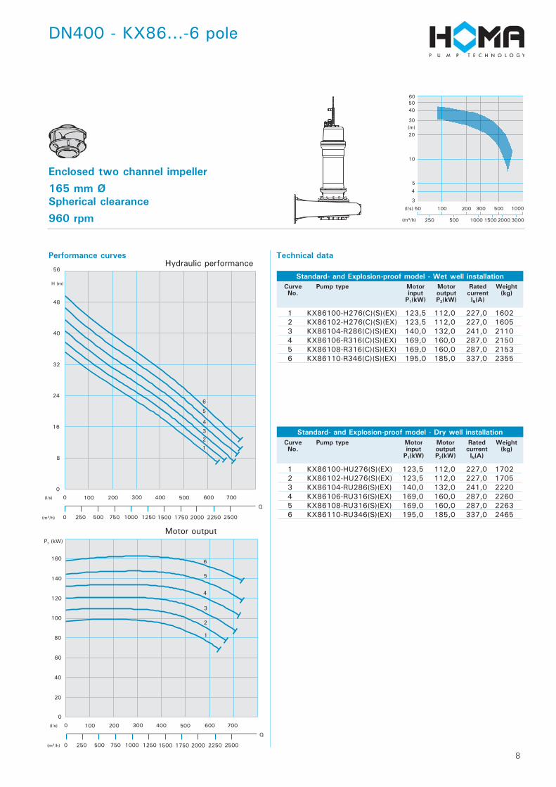
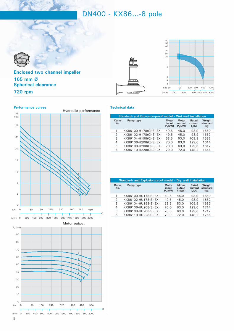
Enclosed two channel impeller165 mm ØSpherical clearance960 rpm
DN400 - KX86...-6 pole
Performance curves Technical data
Standard- and Explosion-proof model - Wet well installation
Standard- and Explosion-proof model - Dry well installation
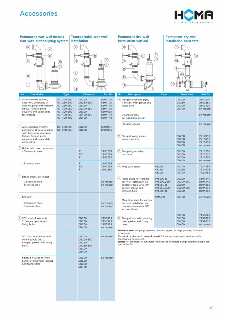
No. Description Type Dimension Part No. No. Description Type Dimension Part No.
Permanent wet well installa-tion with autocoupling system
Transportable wet wellinstallation
Permanent dry wellinstallation vertical
KK 200/200KK 250/200KK 250/250KK 300/250KK 300/300KK 400/350KK 400/400
KS 200/200KS 250/250
DN200DN250/200DN250DN300/250DN300DN400/350DN400
DN200DN250
2“2½“3“
2“2½“3“
DN200DN250DN300DN400
DN200DN200/250DN250DN250/300DN300DN400
DN200DN250DN300DN400
8604100860412086041108604130860409086041448604140
86040818604085
219020521902252190230
219025621902582190260
on requeston request
on requeston request
215336321533732153383on request
on request
on request
Auto-coupling system, cast iron, consisting of auto-coupling with flangedelbow, flanged pump coupling and upper slide rail bracket
Auto-coupling system, consisting of auto-couplingwith horizontal dischargeflange, flanged pump coupling and upper slide rail bracket
Guide rails, pair, per meter- Galvanized steel
- Stainless steel
Lifting chain, per meter
- Galvanized steel- Stainless steel
Shackle
- Galvanized steel- Stainless steel
90° steel elbow with2 flanges, gasket and fixing bolts
90° cast iron elbow with cleaning hole and 2flanges, gasket and fixing bolts
Flanged Y-piece for twin pump arrangement, gasketand fixing bolts
NB200NB250NB300
TVS200 RTVS200/250 RTVS250 RTVS250/300 RTVS300 R
TVM400
DN200DN250DN300DN400
DN200DN250DN300DN400
DN200DN250DN300DN400
DN200DN250DN300
DN200DN200/250DN250DN250/300DN300
DN400
DN200DN250DN300DN400
215020021502502150300on request
on request
on request
221281622168172216300on request
221620022162502216300on request
732129573216757321665
86042408604245860425086042558604260
on request
215982021598252159830on request
Flanged discharge pipe,1 meter, with gasket andfixing bolts
Discharge pipe, per additional meter
Flanged reducer
Flanged swing check valve, cast iron
Flanged gate valve, cast iron
Ring base stand
Pump stand for verticaldry well installation on concrete base with 90° suction elbow andcleaning hole
Mounting plate for verticaldry well installation on concrete base with 90° suction elbow
Flanged pipe with cleaninghole, gasket and fixing bolts
Stainless steel coupling systems, elbows, pipes, fittings (valves, flaps etc.)on request.Electrical or electronic control panels for pumps and pump stations withaccessories on request.Sumps of concrete or synthetic material for complete pump stations please seespecial leaflet.
11
Installations and Dimensions
12
Pump type DN1 DN2 DN3 Amax B B1 C C1 D E F1 F2 F3 øG H J1 J2 K1 K2 K3 K4 L MxM O P1 P2 Q Rmax S1 S3 Tmax Umax V1