Approved for public release; distribution is unlimited. NATIONAL SHIPBUILDING RESEARCH PROGRAM Electric Technologies Panel Meeting Charleston, SC Low Voltage Quick Connector Evaluation Final Outbrief Presented by: Gregory D. Stevens General Dynamics, Bath Iron Works March 12, 2015
Transcript
Approved for public release; distribution is unlimited. NATIONAL SHIPBUILDING RESEARCH PROGRAM
Electric Technologies Panel Meeting Charleston, SC Low Voltage Quick Connector Evaluation Final Outbrief
Presented by: Gregory D. Stevens General Dynamics, Bath Iron Works March 12, 2015
NATIONAL SHIPBUILDING RESEARCH PROGRAM 2
SEE TITLE PAGE FOR DISTRIBUTION CONTROL
Project Mission and Objectives
Currently, using lugged terminal connectors are traditional methods for electrical connection for shock qualified applications
Looking for methods and hardware that support expedited installation, while maintaining high reliability
Ease of use with good electrical characteristics and performance characteristics
Repeatable if mechanism is engaged several times (i.e., during troubleshooting and activation activities)
NATIONAL SHIPBUILDING RESEARCH PROGRAM 3
SEE TITLE PAGE FOR DISTRIBUTION CONTROL
Project Participants
BIW – Lead Bollinger Shipyards Raytheon Dayton T. Brown Laboratories Test Specimen Vendors and Distributors
WAGO Corp. Tyco Electronics Newark Weidmuller Cooper Bussmann
Low Voltage Quick Connector Evaluation Project Goals Research Available Products Evaluate Requirements Generate Evaluation Guide Evaluate Product Information Develop Test Procedure Manufacture Demonstrator Conduct Testing Evaluate Results Generate Report and Recommendations
NATIONAL SHIPBUILDING RESEARCH PROGRAM 5
SEE TITLE PAGE FOR DISTRIBUTION CONTROL
Research Available Products
Several products were researched and chosen as candidates in four basic configurations Standard lugged terminal (baseline) Screw down wire interface Releasable locking mechanism interface Non releasing locking mechanism interface
Using terminal blocks, in-line splices
NATIONAL SHIPBUILDING RESEARCH PROGRAM 6
SEE TITLE PAGE FOR DISTRIBUTION CONTROL
Evaluate Requirements
Several standards and Mil-Specs were reviewed Much of the
requirement review based on types of tests that qualify a particular product
Performance and characteristics testing reviewed
Item Reference Distribution Section Section Language Remarks1 MIL-C-55243: Connectors, Plugs, and
Receptacles, Electrical, Quick Connect and Disconnect, 12 Contacts, Medum Power
Not listed (A - Public Release)
3.8 Contact retention. Individual contacts shall be capable of withstanding an axial load of 10 pounds minimum uniformly applied at a rate of 1 pound per second. (see 4.7)
Each Contact shall witstand a load of 10 pounds
(NOTE - Listed as not for new design) 3.1 Contact resistance. The voltage drop across mating contact terminals shall notexceed 20 millivolts when a current of 7.5 amperes is applied (see 4.9).
Resistance between two connected terminals will be 2.67mΩ or less
3.11 Dielectric strength. The connectors shall show no evidence of breakdown whensubjected to a potential of 1500 volts rms, 60 cycles per second, for a minimumof one minute (see 4.10).
Adjacent terminals will be able to handle a 1500V difference without arcing
3.12 Insulation resistance. The insulation resistance shall be not less than 1000megohms except for unmated connectors following the immersion test when itshall be not less than 100 megohms (see 4.11).
1000MΩ minimum insulation resistance between separate terminals.
3.19 Pull. Mated connectors shall withstand an axial pull of not less than 40 poundsapplied to the shell and 25 pounds applied to the cable. The force shall beapplied abruptly (see 4.18)
Mated connectors shall withstand 25lbs applied to the cable.
3.21 Temperature cycling. At the extreme temperatures during the test specified inparagraph 4.20, the connectors shall be capable of being mated and unmated.
Connectors shall function during Method 102A test condition D of MIL-STD-202
4.21 Vibration (see 3.22). Mated connectors shall be tested in accordance with Method 201 of Standard MIL-STD-202.
Connectors shall function during vibration test.
2 MIL-DTL-22992: Connectors, Plugs, and Receptacles, Electrical, Waterproof, Quick Disconnect, Heavy Duty Type, General Specification for
Not listed (A - Public Release)
3.7 Contact resistance. When connectors are tested as specified in 4.6.4, theresistance of mated pin and socket contacts shall be such that the potentialdrop at the test current specified in table I shall not be greater than the valuesspecified.
Contact resistance depends on Contact size. (EX: Size 16, 20A current, 25mV maximum drop, 1.25mΩ. Increases as Contact size increases)
3.8 Dielectric withstanding voltage. When connectors are tested as specified in 4.6.5, connectors shall be capable of withstanding the applicable voltages shown in table II without flashover or breakdown.
Maximum voltages at sea level range from 1000VAC to 7000VAC based on rating.
3.11 Contact retention. When contacts are tested as specified in 4.6.8, they shall be capable of withstanding the axial loads shown in table III.
Contact retention depends on size. Withstand axial loads ranging from 10lbs to 35lbs between size 16 and 4/0
3.13 Insulation resistance. When connectors are tested as specified in 4.6.10, the insulation resistance (prior to conditioning) shall not be less than 5,000 megohms
Insulation resistance minimum of 5000MΩ
3.17 Cable pull-out. When connectors are tested as specified in 4.6.14, test cables (see 4.4.3) shall not pull-out when the loads given in table V are applied, nor shall slippage exceed .125 inches (3.18 mm)
Cables shall withstand loads from 50-125lbs of fource (based on weight of cable) without slipping more than 0.125"
4.6.6 Thermal shock (temperature cycling). Unmated connectors shall be tested in accordance with test procedure EIA-364-32, condition I, 5 cycles, except that the high temperature shall be 125°C, +3°C - 0°C (see 3.9).
Connectors shall withstand temperatures detailed in EIA-364-33
References and Standards for Cable Terminations and Connectors
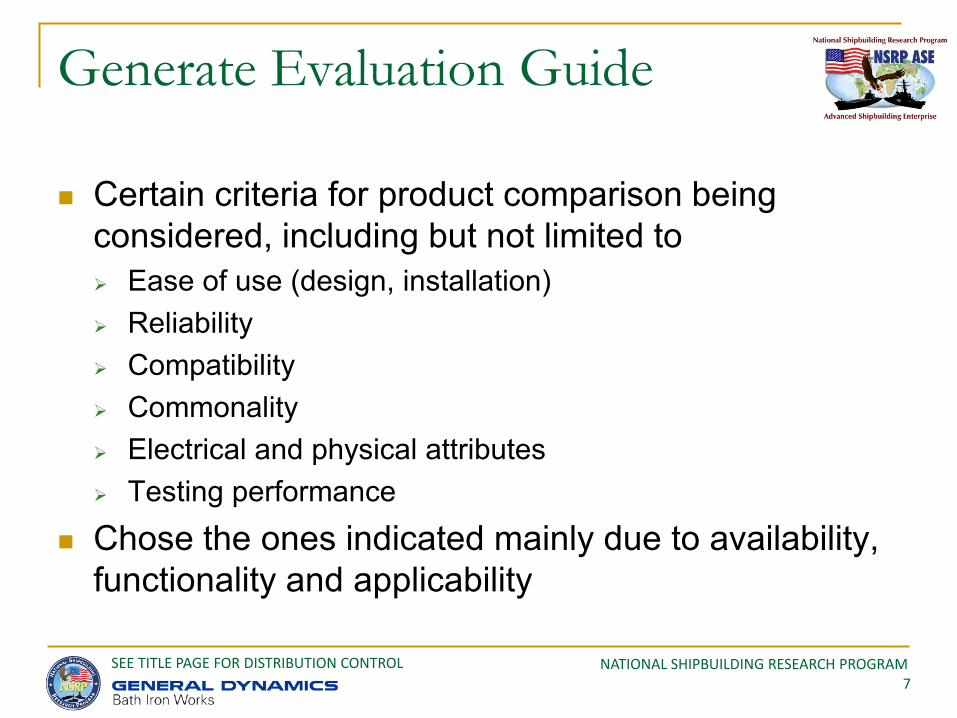
Certain criteria for product comparison being considered, including but not limited to Ease of use (design, installation) Reliability Compatibility Commonality Electrical and physical attributes Testing performance
Chose the ones indicated mainly due to availability, functionality and applicability
NATIONAL SHIPBUILDING RESEARCH PROGRAM 8
SEE TITLE PAGE FOR DISTRIBUTION CONTROL
Evaluate Product Information
The previous evaluation guide templates were filled in with vendor data
This enables a consistent comparison across samples and attributes
Allows for a down select to build unit demonstrators with sample materials
NSRP ETP Project: Low Voltage Quick Connectors, Vendor and Product Information Evaluation
Dimensions Mounting
Item Name Model/PN Product Description Length Width Heighth No.
Connections Conductor Size Rated Voltage Rated Surge Voltage Rated Current Rated SSC Metal Plastic DIN Rail
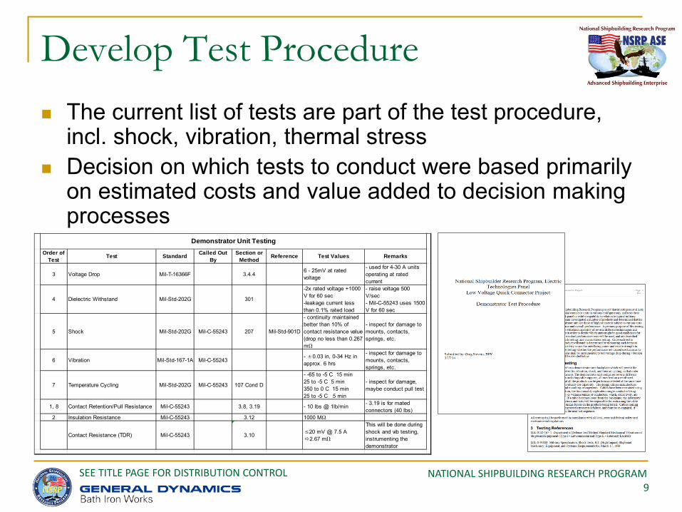
This will be done during shock and vib testing, instrumenting the demonstrator
Demonstrator Unit Testing
NATIONAL SHIPBUILDING RESEARCH PROGRAM 10
SEE TITLE PAGE FOR DISTRIBUTION CONTROL
Design Demonstrator
2 plates, 19.5” wide by 16.5” tall surface for test specimens
Plates are crimped and flanged to increase strength
Made from 0.1” Al stock similar to what is used for various types of boxes in various ship designs
NATIONAL SHIPBUILDING RESEARCH PROGRAM 11
SEE TITLE PAGE FOR DISTRIBUTION CONTROL
Design Demonstrator (cont.)
Plates mounted to test anvil plate at 8 points
Plexiglass and stand-off units can be used to maintain safe testing environment when units are instrumented and energized
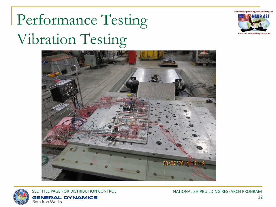
Standard Shock 901D and Vib 167 tests were done on lightweight machines, 3 dimensions
NATIONAL SHIPBUILDING RESEARCH PROGRAM 12
SEE TITLE PAGE FOR DISTRIBUTION CONTROL
Design Demonstrator (cont.)
Product list includes terminal blocks and in-line connectors, most mounted on DIN rail Wago Tyco Cooper
Bussman Ideal 3M
Eaton Cutler Hammer
Weidmuller Rockwell
Automation Phoenix Contact
NATIONAL SHIPBUILDING RESEARCH PROGRAM 13
SEE TITLE PAGE FOR DISTRIBUTION CONTROL
Manufacture Demonstrator Pre cable installation
Test Plate #1 Test Plate #2
NATIONAL SHIPBUILDING RESEARCH PROGRAM 14
SEE TITLE PAGE FOR DISTRIBUTION CONTROL
Manufacture Demonstrator Pre cable installation (cont.)
NATIONAL SHIPBUILDING RESEARCH PROGRAM 15
SEE TITLE PAGE FOR DISTRIBUTION CONTROL
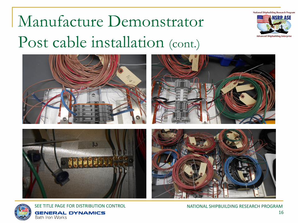
Manufacture Demonstrator Post cable installation
Test Plate #1 Test Plate #2
NATIONAL SHIPBUILDING RESEARCH PROGRAM 16
SEE TITLE PAGE FOR DISTRIBUTION CONTROL
Manufacture Demonstrator Post cable installation (cont.)
NATIONAL SHIPBUILDING RESEARCH PROGRAM 17
SEE TITLE PAGE FOR DISTRIBUTION CONTROL
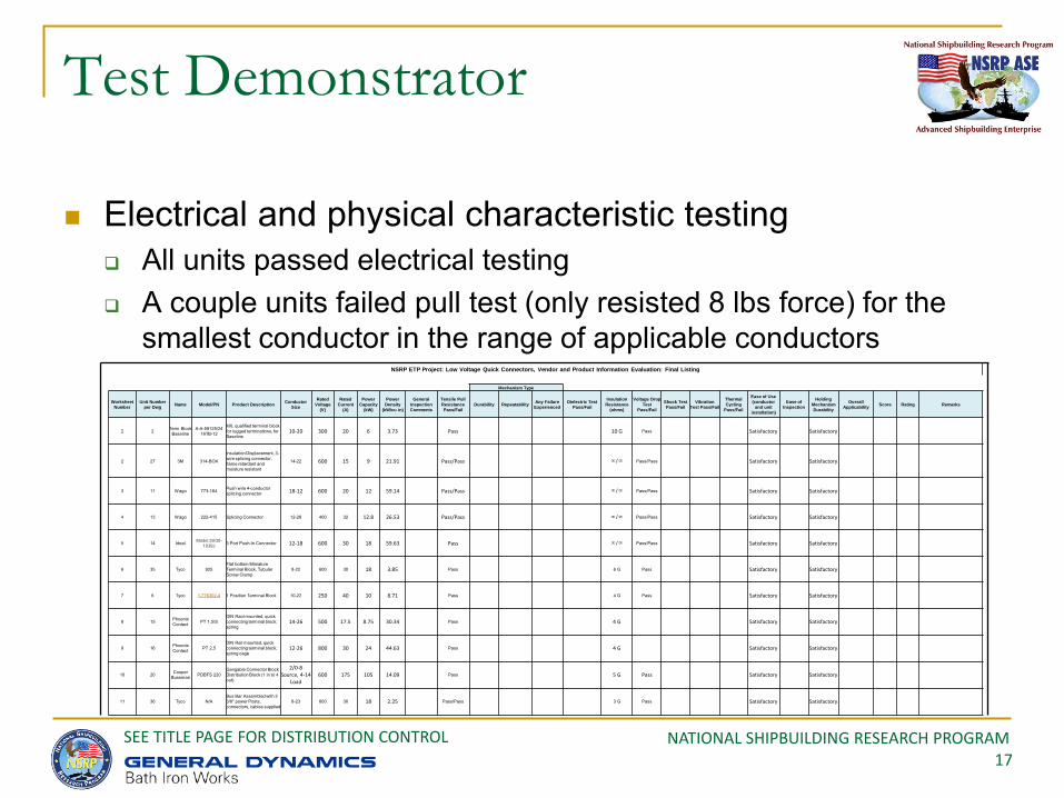
Test Demonstrator
Electrical and physical characteristic testing All units passed electrical testing A couple units failed pull test (only resisted 8 lbs force) for the
smallest conductor in the range of applicable conductors NSRP ETP Project: Low Voltage Quick Connectors, Vendor and Product Information Evaluation: Final Listing
Mechanism Type
Worksheet Number
Unit Number per Dwg Name Model/PN Product Description Conductor
Size
Rated Voltage
(V)
Rated Current
(A)
Power Capacity
(kW)
Power Density
(kW/cu in)
General Inspection Comments
Tensile Pull Resistance Pass/Fail
Durability Repeatability Any Failure Experienced
Dielectric Test Pass/Fail
Insulation Resistance
(ohms)
Voltage Drop Test
Pass/Fail
Shock Test Pass/Fail
Vibration Test Pass/Fail
Thermal Cycling
Pass/Fail
Ease of Use (conductor
and unit installation)
Ease of Inspection
Holding Mechanism Durability
Overall Applicability Score Rating Remarks
1 2 Term Block Baseline
A-A-59125/24 16TB-12
MIL qualified terminal block for lugged terminations, for Baseline
Notes: 1 For those cells showing Pass/Pass, 2 conductors for the connector were tested2 For those cells showing Pass/Pass, voltage drop was measured across connector terminated port and unterminated port, for each conductor
4 No connector test failure or damage. Fastening zip tie broke while testing.5 Disconnected from DIN rail6 Chatter present7 Connector Damage
NSRP ETP Project: Low Voltage Quick Connectors, Testing Results
3 For those cells showing /, measurement was made from conductor to ground, for each conductor; for the other units, worst case was across
NATIONAL SHIPBUILDING RESEARCH PROGRAM 21
SEE TITLE PAGE FOR DISTRIBUTION CONTROL
Performance Testing Shock Testing
NATIONAL SHIPBUILDING RESEARCH PROGRAM 22
SEE TITLE PAGE FOR DISTRIBUTION CONTROL
Performance Testing Vibration Testing
NATIONAL SHIPBUILDING RESEARCH PROGRAM 23
SEE TITLE PAGE FOR DISTRIBUTION CONTROL
Performance Testing Thermal Cycle Testing
NATIONAL SHIPBUILDING RESEARCH PROGRAM 24
SEE TITLE PAGE FOR DISTRIBUTION CONTROL
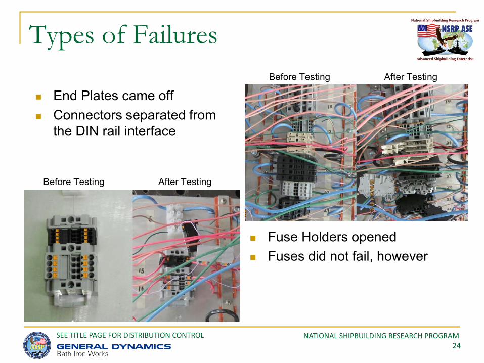
Types of Failures
End Plates came off Connectors separated from
the DIN rail interface
Fuse Holders opened Fuses did not fail, however
Before Testing After Testing
Before Testing After Testing
NATIONAL SHIPBUILDING RESEARCH PROGRAM 25
SEE TITLE PAGE FOR DISTRIBUTION CONTROL
Types of Failures (cont.)
Foot mounting interface broke
Inter unit interfaces broke, causing unit separations
Zip Ties broke (temporary constraints not part of test article design)
Conductors came loose from the connector
Before Testing After Testing
Before Testing After Testing
NATIONAL SHIPBUILDING RESEARCH PROGRAM 26
SEE TITLE PAGE FOR DISTRIBUTION CONTROL
Per unit calculator was used to apply to estimated ship quantities Numbers represent nominal values Hourly rates are arbitrary for demonstration purposes Per unit savings are small Methods and values are conservative in nature
Cost Benefit Assessment
Item Description Base Mounting Device Mounting Wire Preparation Wire Installation Torquing Device Associated Hardware Base Mount Labor
Notes: 1. The above information is an average of several inputs2. The above information represents a per unit basis3. DIN rail mounting estimates is for a strip 24" long, able to hold 40 quick connectors (and end hardware and spacers): takes 30 min. to install 40 units, or 30 sec. pu4. Wire installation is for input and output sides of respective units5. Existing terminal strip is divided by the number of terminal pairs (12)6. Costs are averages across the cross section of units investigated (there is considerable difference, but value can be adjusted easily)7. Associated hardware includes mounting screws, endplates and spacers (where applicable)8. Differences is the quick connector method minus the traditional method9. A positive ROI indicates a savings10. Spreadsheet designer entry11. Labor Hourly cost $: 100
Cost Differences in Traditional Connectors and Quick Connectors
Materials ($)Labor (min) Totals Difference from Traditional Methods
NATIONAL SHIPBUILDING RESEARCH PROGRAM 27
SEE TITLE PAGE FOR DISTRIBUTION CONTROL
Using estimated equipment quantities and per unit values: Savings are calculated for switching all to new quick connectors Savings are calculated for switching % of available opportunities to QC (not part
of purchased equipment) Modest savings over multiple programs reported
Cost Benefit Assessment (cont.)
DIN rail 35 Mounted Quick Connector
Foot Mounted Quick Connector
Currently used Terminal Block
In-Line Splice Connetcor
Lugged Splice Termination Total
Program Average 96,188 32,063 4,050 132,300
DIN rail 35 Mounted Quick Connector
Foot Mounted Quick Connector
Currently used Terminal Block
In-Line Splice Connetcor
Lugged Splice Termination Total
Program Average ($1,737) $265 ($394) ($1,865)
DIN rail 35 Mounted Quick Connector
Foot Mounted Quick Connector
Currently used Terminal Block
In-Line Splice Connetcor
Lugged Splice Termination Total
Program Average ($100,119) $29,391 ($9,315) ($80,044)
DIN rail 35 Mounted Quick Connector
Foot Mounted Quick Connector
Currently used Terminal Block
In-Line Splice Connetcor
Lugged Splice Termination Total
Program Average ($101,856) $29,656 ($9,709) ($81,908)Note: Negative values indicate a savings
Opportunity to Switch to Quick Connectors: From Terminal Blocks and Lugged Splice Connectors to Quick Connectors
Opportunity Costs to Switch to Quick Connectors from Terminal Blocks and Lugged Splice Connectors: Labor Savings (mhrs)
Opportunity Costs to Switch to Quick Connectors from Terminal Blocks and Lugged Splice Connectors: Hardware Savings ($)
Opportunity Costs to Switch to Quick Connectors from Terminal Blocks and Lugged Splice Connectors: Total ($)
NATIONAL SHIPBUILDING RESEARCH PROGRAM 28
SEE TITLE PAGE FOR DISTRIBUTION CONTROL
Using estimated quantities to replace that are not purchased with equipment Small savings shown These estimates do not include NRE to change to new design Numbers are conservative A lot are purchased with equipment
Cost Benefit Assessment (cont.)
DIN rail 35 Mounted Quick Connector
Foot Mounted Quick Connector
Currently used Terminal Block
In-Line Splice Connetcor
Lugged Splice Termination
Total
Average 3,059 532 452 3,741
DIN rail 35 Mounted Quick Connector
Foot Mounted Quick Connector
Currently used Terminal Block
In-Line Splice Connetcor
Lugged Splice Termination Total
Average (489) (71) (108) (595)
DIN rail 35 Mounted Quick Connector
Foot Mounted Quick Connector
Currently used Terminal Block
In-Line Splice Connetcor
Lugged Splice Termination Total
Average (3,184) 487 (1,040) (3,043)
DIN rail 35 Mounted Quick Connector
Foot Mounted Quick Connector
Currently used Terminal Block
In-Line Splice Connetcor
Lugged Splice Termination Total
Average (3,672) 417 (1,148) (3,638)Note: Negative values indicate a savings
Opportunity Costs to Switch to Quick Connectors from Terminal Blocks and Lugged Splice Connectors: Labor Savings (mhrs)
Opportunity Costs to Switch to Quick Connectors from Terminal Blocks and Lugged Splice Connectors: Total ($)
Opportunity to Switch to Quick Connectors: From Terminal Blocks and Lugged Splice Connectors to Quick Connectors
Opportunity Costs to Switch to Quick Connectors from Terminal Blocks and Lugged Splice Connectors: Hardware Savings ($)
NATIONAL SHIPBUILDING RESEARCH PROGRAM 29
SEE TITLE PAGE FOR DISTRIBUTION CONTROL
Qualified Benefits include: Troubleshooting, testing and commissioning Flexible configuration and minimal impact to adjacent circuits Reduced installation steps Fewer parts to manage COTS (Commercial Off the Shelf) equipment
Qualified benefits may be more important than quantified benefits in some applications
User should determine where relative benefits are generated and costs assessed
Cost Benefit Assessment (cont.)
NATIONAL SHIPBUILDING RESEARCH PROGRAM 30
SEE TITLE PAGE FOR DISTRIBUTION CONTROL
Recommendations
Future Estimation Work Users should use the tools for their programs and refine as
necessary; validation is good practice, but not necessary Universal Requirements
Consider requirements that can be invoked on several types of marine programs
Drive program specific costs out of multiple programs Qualification Program
Vendors to consider ESS qualification Use most stringent requirements, as applicable
Product Resilience Vendors to assess and maintain or improve product resilience for
targeted markets
NATIONAL SHIPBUILDING RESEARCH PROGRAM 31
SEE TITLE PAGE FOR DISTRIBUTION CONTROL
Identify opportunities Identify hardware and methodology availability Determine qualification status Determine qualification scope of work
Estimate costs and schedule associated with qualification
Determine overall cost of change Determine point of technology insertion
Implementation
NATIONAL SHIPBUILDING RESEARCH PROGRAM 32
SEE TITLE PAGE FOR DISTRIBUTION CONTROL
Project investigated a good cross section of quick connector products to consider
All products, for the most part, performed well Some products require re-design to meet the types of
requirements used in the project Other products will likely meet stringent requirements as
they are currently designed Recommend further cost benefit analysis (which
would be part of user implementation plans) Vendors are encouraged to move into qualification