74
I:\H&S\H&S Procedures\Electrical\Act_Electricity\ESMPj 180205-Vol1.docLast printed 5/18/2005 12:32 PM Facilities Management ELECTRICAL SAFETY MANAGEMENT PLAN Volume One
| Date post: | 14-Feb-2018 |
| Category: |
Documents |
| Upload: | hoangkhanh |
| View: | 215 times |
| Download: | 1 times |
I:\H&S\H&S Procedures\Electrical\Act_Electricity\ESMPj 180205-Vol1.docLast printed 5/18/2005 12:32 PM
Facilities Management
ELECTRICAL SAFETY MANAGEMENT PLAN Volume One

I:\H&S\H&S Procedures\Electrical\Act_Electricity\ESMPj 180205-Vol1.doc
PREFACE This Electrical Safety Management Plan is prepared in two volumes as follows: Volume One – documents QUT’s expected approach to electrical safety by its employees and contractors. Volume Two – documents the workplace procedures for some of the more common and/or critical electrical tasks.

I:\H&S\H&S Procedures\Electrical\Act_Electricity\ESMPj 180205-Vol1.doc - 2 -
INDEX
Volume One 1. Introduction..................................................................................................................................................3 2. Objectives of the ESMP...............................................................................................................................3 3. Scope and Limitations..................................................................................................................................3 4. Responsibilities ............................................................................................................................................3 5. Legal Requirements .....................................................................................................................................5 5. Accident Reporting and Investigation..........................................................................................................5 6. Forms and Procedures..................................................................................................................................6 7. Safety ...........................................................................................................................................................6 8. Risk Assessment and Control ......................................................................................................................7 9. Electrical Work ..........................................................................................................................................17 10. Tools, Plant and Equipment .......................................................................................................................17 11. Training and Assessment ...........................................................................................................................18 12. Supervision ................................................................................................................................................19 13. Staff Records..............................................................................................................................................19 14. Defects and Improvement Notices .............................................................................................................19 15. PCBs ..........................................................................................................................................................20
Volume Two Appendicies APPENDIX A SPARE APPENDIX B WORK PROCESS FLOWCHART APPENDIX C SPARE APPENDIX D CONTROL MEASURES FOR TESTING ELECTRICAL EQUIPMENT APPENDIX E SAFETY PRECAUTIONS WHEN WORKING ON ELECTRICAL EQUIPMENT APPENDIX F TESTING OF ELECTRICAL TEST INSTRUMENTS APPENDIX G BEFORE USE INSPECTION OF TEST INSTRUMENTS APPENDIX H TESTING OF ELECTRICAL SAFETY EQUIPMENT APPENDIX I BEFORE USE INSPECTION OF ELECTRICAL SAFETY EQUIPMENT APPENDIX J DANGER, OUT OF SERVICE, WARNING, SAFETY TAG AND LOCK-OUT APPENDIX K EXCLUSION ZONES FOR A PERSON PLANT OR A VEHICLE FOR AN ELECTRICAL PART, APPENDIX L ACCIDENT/INCIDENT REPORTING AND INVESTIGATION APPENDIX M VISUAL SAFETY EXAMINATION OF AN ELECTRICAL INSTALLATION APPENDIX N TESTING AN ELECTRCIAL INSTALLATION APPENDIX O - SERVICING FLUORESCENT LIGHTS APPENDIX P – SAFE HANDLING AND DISPOSAL OF PCB CONTAINING EQUIPMENT (FLUORESCENT LIGHT FITTINGS) Forms APPENDIX FORM AA - SAFETY, COMPETENCY AND PROCEDURE AUDIT – ELECTRICAL WORKER APPENDIX FORM BB - SAFETY, COMPETENCY AND PROCEDURES AUDIT SCHEDULE APPENDIX FORM CC - INSTRUMENT TEST SCHEDULE APPENDIX FORM DD - ON SITE RISK ASSESSMENT APPENDIX FORM EE – CONTROL MEASURES FOR COMMON RISK ASSESSMENTS APPENDIX FORM FF – ELECTRICAL TEST REPORT APPENDIX FORM GG – SAFETY EQUIPMENT INSPECTION SCHEDULE APPENDIX FORM HH – LIVE WORK CHECKLIST APPENDIX FORM II – ELECTRICAL SAFETY REPORT APPENDIX FORM JJ – VISUAL INSPECTION CHECKLIST

I:\H&S\H&S Procedures\Electrical\Act_Electricity\ESMPj 180205-Vol1.doc - 3 -
1. Introduction
New Electrical Safety legislation was enacted in Queensland in October 2002. The legislation is closely aligned with occupational health and safety legislation.
The purpose of this legislation is to—
• prevent persons from being killed or injured by electricity; and
• prevent property from being destroyed or damaged by electricity.
The University, through the Facilities Management Department, has a legal obligation under the Electrical Safety Act and Regulation 2002 as a person in control of premises and electrical equipment, as an employer, as an installer of electrical infrastructure and as a repairer of electrical infrastructure. These obligations require the university to ensure any electrical installation or electrical equipment which forms part of the business of the university is electrically safe and any electrical installation work performed by university staff is electrically safe.
The purpose of this Electrical Safety Management Plan (ESMP) is to address Facilities Management’s (FM) legal obligation to ensure the health and safety of persons/parties at their workplaces under the Electrical Safety Act. The ESMP is a working document designed to effectively manage and minimise health risks associated with work on electrical equipment and installations on University sites. The ESMP is to be read in conjunction with relevant Acts, Regulations, Codes of Practice, Australian Standards and other relevant legislation and documents, including the QUT Electrical Safety Policy.
2. Objectives of the ESMP
The overall aim of the ESMP is to ensure the safety of, and minimise the potential harm to, human health and property associated with working on electrical equipment and installations controlled by FM . The ESMP sets the minimum safety standards for electrical work being undertaken by FM staff and FM Contractors on behalf of FM.
3. Scope and Limitations
This document has been developed specifically for the Queensland University of Technology – FM and applies only to those properties and facilities that are either owned and/or leased by the University. This ESMP does not cover electrical equipment and installations under the control of other Divisions/Faculties.
This document is only applicable to low voltage work. For the purposes of QUT, low voltage installations or systems include any and all electrically operated circuits, apparatus, components and networks in which the electrical voltage is at or below 1000Volts a.c. or 1500Volts d.c., including extra low voltage.
4. Responsibilities Person Responsibility
FM Department The FM Department is responsible for the operational aspects of facilities management. These include the management of major and minor capital and maintenance projects and the provision of expert advice on site services, maintenance and restoration of the physical fabric of the University. For the purpose of the Act FM is the “Person In

I:\H&S\H&S Procedures\Electrical\Act_Electricity\ESMPj 180205-Vol1.doc - 4 -
Control.”
Approval of Electrical Safety Management Plan (ESMP)
Director, FM
Ensure FM compliance with ESMP through the Manager Maintenance Services
Allocate funding for management of electrical safety.
Associate Director Operations, Associate Director Capital Works
Ensure all FM staff working for them and their sections are aware of and comply with the ESMP.
Ensure Contractors are made aware of the ESMP and the fact that their Safety Plans must address the requirements of the Electrical Safety Act and the ESMP.
Manager – Maintenance Services (MMS)
Develop and maintain ESMP.
Provide training, information and awareness for FM staff.
Provide PPE for staff.
Allocate funding for management of electrical safety.
Approve live work Risk Assessments
Electrical Mechanical Services Supervisor (EMSS)
Ensure compliance with the ESMP for QUT FM staff
Ensure the use of PPE for FM staff
Preparation of Risk Assessments for all live work. Assessments approved by MMS
Principal Contractors, Subcontractors, QUT Staff
Strict adherence to the Electrical Safety Management Plan, other relevant standards, and work methods.
Use PPE where the equipment is provided and intended for use.
Qualified Technical Person (previously Electrical Endorsee)
Qualified Technical Persons shall be foreperson who must :
o Submit documents required under the Act about performance of electrical work.
o Arrange training, conduct electrical audits, and inspections of FM electrical workers and report their compliances/non-compliances to Manager, Maintenance Services via the Electrical Mechanical Services Supervisor.
o Ensure FM electrical workers electrical licences are appropriate and current and
I:\H&S\H&S Procedures\Electrical\Act_Electricity\ESMPj 180205-Vol1.doc - 5 -
maintain records of such.
o Maintain records of electrical work they are responsible for.
5. Legal Requirements Prescriptive Requirements
Clause (4) of the Electrical Safety Regulations 2002 outlines how the purposes of the Regulation are to be achieved. This includes prescribing ways of discharging electrical safety obligations, including introducing restrictions on live work and working near exposed electrical parts, and also requirements for safety management plans.
In response to the above legal obligation and in recognition of the obvious hazards, FM provides this management plan to achieve the requirements of the Regulations.
Legislation
The following is a list of some of the references that detail the legal requirements for safely working on electrical equipment and installations in Queensland.
• Electricity Safety Act 2002
• Electricity Safety Regulation 2002
• Code of Practice – Electrical Work
• Code of Practice – Working near exposed live parts
• Code of Practice – Works (protective earthing, underground cable systems and maintenance of supporting structures for powerlines)
• The Guide – Electrical Safety Act 2002
• Explanatory Notes for Electrical Safety regulation 2002
• QUT Electrical Safety Policy
• Workplace Health and Safety Act 1995
• Workplace Health and Safety Regulations 1997
• Australian standards:
• 3000 Electrical Wiring Rules
• 1892.1,2,3 Portable ladders
• 3012 Electrical Installations-Construction and Demolition sites
• 3760 - 2003 In-service safety inspection and testing of electrical equipment
• 4836 Safe Working on Low Voltage Electrical Installations
5. Accident Reporting and Investigation
All electrical incidents that could result or do result in a person being injured

I:\H&S\H&S Procedures\Electrical\Act_Electricity\ESMPj 180205-Vol1.doc - 6 -
must be immediately reported to the MMS, through the EMSS. The accident/incident will be reported and actioned in accordance with QUT policy as per Appendix L.
6. Forms and Procedures
Forms and procedures are contained in the Appendices and listed in the Contents
7. Safety Safety Policy
FM will fulfil their obligations under the Electrical Safety Act 2002 and Electrical Safety Regulation 2002 by:
• Developing operational requirements and advising staff and contractors of their responsibilities.
• Developing operational procedures and providing training to staff to ensure that all work complies with requirements and is electrically safe.
• Ensuing that all electrical equipment, tools and safety equipment is regularly tested/examined to enable all work to be completed in a safe manner.
• Instructing staff in the correct use of PPE and other equipment so that all persons have the knowledge to work safely and ensure a safe work place for others.
Employees and Contractors will fulfil their obligations under the Electrical Safety Act 2002 and Electrical Safety Regulation 2002 by:
• Complying with employer instructions and ensuring that any electrical work completed is safe.
• Using PPE, instruments, tools and safety equipment to complete all work in a safe manner and in compliance with legislative requirements.
• Not wilfully interfere or misuse anything that may create an unsafe situation for themselves and others.
• All workers will adopt a “test before touch” approach and treat all conductors and equipment as live until proven otherwise
• Every safety incident or accident will be reported and investigated in accordance with the Accident Reporting and Investigation Policy (see Section 25.1 and Appendix ‘L’)
• Ensuring site safety plans comply with the ESMP Personal Protective Equipment
Staff and Contractors at the worksite will use Personal Protective Equipment (PPE) relevant to the work being carried out. It is the responsibility of each employee and Contractor to regularly examine their PPE to ensure it is in a satisfactory condition so that work may be carried out safely.
Audits of FM employees by the Qualified Technical Persons will be conducted as per Appendix Form AA to ensure PPE is being used appropriately and is in a satisfactory condition. It is the responsibility of Contractor employers to undertake audits of Contractor employees.
Safety Equipment
I:\H&S\H&S Procedures\Electrical\Act_Electricity\ESMPj 180205-Vol1.doc - 7 -
Staff and Contractors at the worksite will use safety and operating equipment relevant to the work being carried out. It is the responsibility of every FM employee and Contractor to regularly examine all items of safety equipment they are using to ensure the equipment is in-test and is in a satisfactory condition for the work being carried out.
Audits of FM employees by the Qualified Technical Persons will be conducted to ensure safety equipment is being used appropriately and is in a satisfactory condition. It is the responsibility of Contractors to undertake audits of contractor employees
Site Safety
To ensure the safety of electrical workers, isolation points will be locked and tagged in accordance with the procedure as per Appendix J, or for Contractors, their company procedure that must be of at least equal standard. This is also a requirement of the Electricity Safety Regulation 2002.
Safety in Installations
If an unsafe situation is discovered in an installation the MMS, through the EMSS, is to be advised immediately.
If unsatisfactory electrical installation work completed by an electrical contractor is discovered, an Unsatisfactory Electrical Installation Report (Appendix Form II) will be completed and forwarded to the MMS.
Visual Safety Inspection of Electrical Installations
This may be required in conducting audits of works carried out by in-house or external electrical workers to gauge work standard, and/or when concern has been raised about standard of work.
The procedure to be followed is as per Appendix M.
Site Inspection before Leaving
Before leaving the site a visual inspection will be conducted to ensure that all cables have been correctly terminated, the installation is electrically safe, completed work complies with the relevant standards and is in accordance with the customer’s requirements.
8. Risk Assessment and Control General
The requirement of the electrical safety legislation is that live electrical work is only to be carried out when at least one of the following situations exist:
a) It is necessary in the interests of safety, whether or not electrical safety, for the work to be performed while the electrical equipment the subject of the electrical work is energised
b) A supply of electricity is necessary to performing the electrical work.
c) There is no reasonable alternative to performing the electrical work by live work.
QUT FM will comply with the requirements of the Electrical Safety Act 2002 with regard to live work. To this extent NO live work is to be carried out by FM staff

I:\H&S\H&S Procedures\Electrical\Act_Electricity\ESMPj 180205-Vol1.doc - 8 -
or Contractor employees, with the exception of testing or fault finding, or emergencies, and then ONLY when no other reasonable alternative is possible.
“Live Work” means electrical work performed in circumstances in which some or all of the electrical equipment the subject of the electrical work is energised.
The location of faults should first be attempted with the supply safely isolated, and by utilising de-energised testing methods.
“Emergency” means when after a written risk assessment has been completed, it is determined the risk of personal injury or loss of life is greater than the risk of de-energising.
Live Work can only occur following a risk assessment and the implementation of suitable control measures. In the following text the practice of identifying hazards and assessing and controlling the risks is outlined in detail.
Identifying the Hazards
Notwithstanding the fact that QUT FM does not allow any live work, except faultfinding and testing, or emergencies, it is useful to review many of the more common forms of hazards found in the electrical workplace, even though some of them will be eliminated by ensuring that the subject of the work has been de-energised.
The first step is to identify the sources of exposure to electricity and other related hazards. To do this, you could break the workplace or tasks down into areas and then identify the hazards in each area. 'Stocktake' your workplace hazards to be sure you identify all the sources of electricity or stored electrical energy, to which people may be exposed. Below are examples of typical sources of hazard that, individually or in combination, could lead to electric shock or severe injury. The list is not in order of priority.
a) Voltages between phases.
b) Voltages between phases and earth.
c) Voltages between live exposed conductors and surrounding metal framework.
d) Voltages across undischarged capacitors.
e) Voltages on disconnected conductors - particularly neutrals.
f) Multiple supply sources (more than one source of supply or live circuit may be available on the premises).
g) Voltages between live exposed conductors and the surrounding environment (including metalwork, damp situations, other conductive surfaces and persons nearby).
h) Electrical testing or operating equipment with open enclosures in hazardous areas (as defined by AS/NZS 3000:2000).
i) Lower voltages - for example ELV (extra low voltage) may be hazardous in a cramped situation with dampness, heat or water on the floor, especially when the worker is lying on the floor.
j) In installations or systems where the MEN (multiple earthed neutral) system is used, the rise in the earth potential in an installation due to a high

I:\H&S\H&S Procedures\Electrical\Act_Electricity\ESMPj 180205-Vol1.doc - 9 -
impedance return path to the distribution neutral.
k) Damp conditions.
l) Switched off circuits becoming live. Induced voltages.
m) Induced voltages Examples of work involving common hazards
Some other common, non-electrical hazards which may be encountered in electrical work include:
a) confined spaces (where there may be a hazardous atmosphere - see below);
b) lack of sufficient light to work safely;
c) lack of ventilation leading to uncomfortable, hot and humid working conditions;
d) excessive fatigue, due to pressure of deadlines or other factors;
e) obstacles to getting the equipment switched off;
f) using a gas flame near exposed electrical conductors (a flame is a conductor);
g) temperature rise as a result of combustion;
h) fall from heights;
i) cramped working conditions;
j) explosive atmospheres;
Hazard Work activity
Voltage between phases • Working on polyphase installation or systems. • Wiring/testing/servicing of switchboards/motors/
heaters/ controllers. • Working on exposed busbars/catenary wires etc.
Voltage between phases and earth • Working on single phase & polyphase systems. • Wiring/testing/servicing of
switchboards/motors/heaters/ controllers. • Working on exposed busbars/catenary wires etc. • General electrical work.
Voltage across undischarged capacitors
Work with apparently isolated plant with reactive storage components.
Multiple supply sources Working in large installations or systems with standby power systems, multiple distribution boards, where source of power in a single location or zone is uncertain, such as solar energy sources.
Electrical testing in hazardous locations
Electrical testing in confined area with explosive gas mixture, fumes, vapour or dust which is inadequately ventilated.
Damp working conditions Working in situations where condensation, spillage, drainage or seepage occurs and results in wet surroundings.

I:\H&S\H&S Procedures\Electrical\Act_Electricity\ESMPj 180205-Vol1.doc - 10 -
k) static from clothing made from wool, wool blends, nylons and polyvinyl (unless treated with an anti static process);
l) electric tools and equipment (e.g. hand lamps, drills, saws, torches and test instruments);
m) personal effects (e.g. rings, jewellery, cigarette lighters, matches, hearing aids, mobile phones and pagers, transistor radios and similar);
n) general work activities (e.g. welding, cutting, brazing, using hand saws, drilling of all types, hammering and chiselling);
o) static from the rubbing (friction effects) of plastics;
p) hot metal surfaces due to drilling, grinding welding, etc;
q) use of metallic tape measures;
r) excavation associated with electrical work; and
s) molten metal from arcs.
Examples of confined spaces are:
a) storage tanks, process vessels, boilers, pressure vessels, silos, and other tank like compartments;
b) open topped spaces such as pits and degreasers; and
c) pipes, sewers, shafts, ducts, and similar structures. Note: there are specific regulatory provisions for entry into confined spaces, not covered in this manual.
Some common ‘electrical hazards’ specific to fault finding and testing are:
a) Electric shock causing injury or death. The electric shock may be received by direct contact, tracking through or across a medium, or by arcing;
b) Arcing, explosion or fire causing burns. The injuries are often suffered because arcing or explosion or both occur when high fault currents are present; and
c) Toxic gasses causing illness or death. Burning and arcing associated with electrical equipment causes a range of gases and contaminants to be present. Compounds ranging from ozone to cyanide and sulphuric acids can be present as well as the hazards such as low oxygen content in the air.
d) All these hazards may be present individually or combined. Assessing the Risks Having identified hazards, the next step is your risk assessment, which will then consider the likelihood and how serious a problem each hazard could create. You could do this area by area, or task by task, in order to make this task more manageable (if you have not done so already at the hazard identification stage). Risk is a combination of likelihood that something will occur and how serious (severe) the consequences are. Start with severity, by making a list of the identified hazards in the order of severity of potential injury, from fatal through to minor injury. Then, next to each item on this list, write down the number of
I:\H&S\H&S Procedures\Electrical\Act_Electricity\ESMPj 180205-Vol1.doc - 11 -
times and/or the length of time workers are exposed to each hazard. This will tell you how likely each hazard will occur. The combination of severity and likelihood determines the level of risk. Consider both of these factors to provide a new order of priority. This will be approximate - an exact quantification is not required. A rough estimate will help you to prioritise the risks. For example, a combination of long or frequent exposure and the possibility of severe injury would mean the hazard should be placed high on the priority list. A combination of short or infrequent exposure and the possibility of slight injury would mean the hazard should be placed low on the priority list. The purpose of prioritising the risks is to give you an order in which they should be addressed, and the extent of control required however, all risks must be controlled, irrespective of the level of risk. The priority order is not as important as ensuring that all hazards are addressed. The needs of individual workers also need to be identified. The following sections examine in more detail the types of things to consider when assessing the risks associated with identified hazards. Identifying Individual Needs When assessing the risk, any one of the following factors triggers special consideration of individual workers’ needs:
a) Is the person physically fit for a task involving exposure to low voltage electricity (e.g. are they able to climb to heights to work on an overhead conductor)?
b) Does the worker have a visual deficiency (e.g. do they have a visual colour deficiency)?
c) Do they suffer from any heart, circulatory or other diseases (e.g. do they have a pacemaker)?
d) Are they taking any medication which may increase their vulnerability to work in electrical environments (e.g. are they being treated for epilepsy)?
e) Are staff working excessively long hours?
f) Are they experienced in, and have they been properly trained for, the working conditions?
g) Do they suffer from claustrophobia? Risk Factors when Modifying Existing Electrical Installations or Systems Examples of common risk factors with existing installations or systems include:
a) The supply may become live during the work;
b) Automatic starting of machinery after supply is restored;
c) A conductor that was thought to be de-energised was found to be live;
d) More than one source of supply or live circuit may be available on the premises;
e) Old installations or systems (where several modifications may have been

I:\H&S\H&S Procedures\Electrical\Act_Electricity\ESMPj 180205-Vol1.doc - 12 -
made, circuits have not been identified, or the insulation has deteriorated);
f) Voltages on disconnected conductors - particularly neutrals;
g) Installations or systems where the MEN system is used, the rise in the earth potential due to a high impedance return path to the distribution neutral;
h) Lack of information about isolation, sources of supply, or the location of electrical conductors;
i) Lack of clear safe access to locate electric cables (other hazards may be present such as exposed conductors);
j) Damage to conductors in metallic conduits where earthing continuity of the conduit has not been maintained;
k) Equipment located in hazardous areas, which often includes bolt-on or screw on covers, can be dangerous if opened without obtaining specialist advice;
l) Working alone on live equipment or installations;
m) Contact with cables during excavation.
Risk factors in fault-finding and repair work Risks arise because it is sometimes difficult to find faults or malfunctions in electrical equipment when the equipment is not operating. This is particularly so if feedback circuits or sensors are involved. Some common risk factors in fault finding or repair include:
a) Exposed live terminals;
b) Terminals or conductors being live under different conditions of operation of the equipment;
c) Loose or disconnected leads becoming live;
d) Test equipment conducting the potential closer to the electrical worker;
e) Test equipment inappropriate for the task (particularly test probes);
f) Test points inadequate;
g) Inadvertent attempts to start machinery by other persons;
h) Incorrect or poorly-maintained testing instruments;
i) Inadequate knowledge of equipment or causes of faults;
j) Lack of information about circuits or equipment;
k) Equipment located in hazardous areas, which often includes bolt-on or screw-on covers, can be dangerous if opened without obtaining specialist advice;
l) Working alone on live equipment or installations.

I:\H&S\H&S Procedures\Electrical\Act_Electricity\ESMPj 180205-Vol1.doc - 13 -
WARNING — SWITCHBOARD CUBICAL BUSBARS IN PARTICULAR: ARCS MAY CAUSE AN EXPLOSION AND OR MELT METAL AND RELEASE HOT GASES. SEVERE BURNS AND INJURY FROM FLYING DEBRIS MAY RESULT. OVERCURRENT DEVICES MAY NOT OFFER PROTECTION. Recording the risk assessment
Risk assessment processes and procedures, along with checklists and templates, are set down in the Appendices to this document. All records should indicate the control measures chosen and why: the next section explains this in more detail.
Controlling Risks QUT FM and contractors have legal responsibilities for implementing risk control measures to safeguard employees and other workers against harm arising from low voltage while at work. Having assessed the risks, action must now be taken to ensure that the risks are eliminated or controlled. Both QUT FM and contractors need to ensure adequate supervision of workers to make sure that control measures are applied. Listed below are steps to consider. Every workplace is different, so select the controls that are the right ones for you. Control measures for all electrical work Electrical safety is primarily dependent upon appropriate job planning and correct testing procedures and techniques. The first aim always should be to eliminate the hazard. QUT FM has adopted the policy of ensuring that, for other than fault finding and testing, the electricity supply is always switched off or isolated however, electrical equipment should not be assumed to be de-energised after isolation. Testing must be done prior to touching. It goes without saying that workers must be appropriately trained and competent in test procedures and in the use of testing equipment. You can eliminate the risk of shock or burns by:
a) Switching off the supply;
b) Isolating the supply;
c) Taking precautions to ensure that the supply remains isolated by locking-off and/or tagging, or by disconnecting the load side of the isolator and tying back disconnected conductors;
d) Proving the supply is de-energised by using an approved testing instrument.
WARNING EVEN IF IT IS BELIEVED THAT THE SUPPLY HAS BEEN ISOLATED, IT MUST BE ASSUMED THAT ALL CONDUCTORS AND COMPONENTS ARE LIVE UNTIL THEY HAVE BEEN PROVEN DE-ENERGISED.
I:\H&S\H&S Procedures\Electrical\Act_Electricity\ESMPj 180205-Vol1.doc - 14 -
The electrical worker or supervisor should:
a) Discuss options for de-energising the supply with the person in control of the premises;
b) consider working at another time when the supply can be isolated;
c) Investigate whether the section of the installation that needs to be de-energised can be isolated, while leaving the remainder connected.
If hazards other than energised conductors cannot be eliminated then isolate the hazard from the worker by:
a) Time — do the work when the hazard can be eliminated or isolated: in effect, this is the same as eliminating the hazard.
b) Marking barriers — e.g. using rigid or tape barriers to mark off the adjacent hazards (this is practised in the electricity supply industry in switch-yards).
c) Use of personal protective equipment (PPE) such as:
i.) a safety helmet with face shield (as appropriate);
ii.) safety glasses/face shields (anti-flash);
iii.) safety boots;
iv.) protective clothing;
v.) approved insulating gloves;
vi.) approved insulated tools; and
vii.) approved insulating sheeting. Workers must be trained to be competent in the use of PPE and all the above practices must be described in QUT FM’s and contractors’ safe working procedures.
Advice to workers WORK SAFELY ISOLATE THE SUPPLY SECURE LOCKOUT DEVICE AND TAG PROVE IT IS DE-ENERGISED
Control measures when fault-finding and/or testing on or near Live conductors Fault-finding and/or testing can require live work. When fault finding, take the following precautions:
a) The location of faults should first be attempted with the supply safely isolated, and by utilising de-energised testing methods.
b) If a fault cannot be found with the supply isolated and live testing methods have to be used, put control measures in place that isolate all persons from the hazard. Then, prior to fault finding/testing, the following must be done:

I:\H&S\H&S Procedures\Electrical\Act_Electricity\ESMPj 180205-Vol1.doc - 15 -
i.) Identify exposed conductive parts that could become live whilst using test instruments;
ii.) Use only approved insulated tools, testing probes and isolation barriers should be used to isolate all workers from contact with exposed conductive parts that could become live during testing;
iii.) Conduct periodic review of the situation to ensure that no new hazards are created during the process.
iv.) Follow ‘Control Measures to be taken before working live’ (below);
c) When the fault finding work is completed, circuits and equipment must be restored to a safe condition. For example, disconnected conductors should be reconnected and left in a safe state, covers replaced and accessories and equipment properly secured in compliance with AS/NZS 3000 requirements.
Note that for work in hazardous areas, the special techniques required by AS/NZS 3000 are not covered in this manual. Control measures to be taken before working live Working live procedures can be implemented in emergencies where the risks of de-energising are greater, OR fault finding and testing only: Before live work is commenced the following factors must be applied:
a) A written ‘risk assessment’ for the performance of the live work has been completed. On large or difficult work activities a comprehensive written risk assessment as per Appendix Form DD and a written ‘Checklist for the performance of the live work’ as per Appendix Form HH has been completed. On small or non-complex work activities a written risk assessment a ‘Control Measures for Common Risk Assessments’ guide as per Appendix Form EE may be utilised
b) Identified Control Measures have been implemented. (Appendix Form DD or EE may be utilised);
c) Testing equipment appropriate to the performance of the live work, is available for use by the person performing the electrical work, has been properly maintained, and the person performing the electrical work makes proper use of the testing equipment;
d) Clothing and PPE appropriate to the performance of the live work is being used/worn by the person performing the electrical work and the person performing the electrical work makes proper use of the clothing and equipment.
e) The isolation point of the electricity supply for the electrical equipment the subject of the electrical work has been clearly identified and, except for electric line work, is able to be reached quickly without the need to climb over or shift obstructions;
f) The area where the electrical work is performed is clear of obstructions to the extent necessary for easy access to and from the area;
g) Unauthorised persons must be prevented from entering the work area by signage and/or a barrier.
h) There is a safety observer observing the performance of the electrical work, unless the work involves testing electrical equipment.
i) When fault-finding or testing electrical equipment use a safety observer where risk requires (eg the Risk Assessment as per Appendix Form DD is

I:\H&S\H&S Procedures\Electrical\Act_Electricity\ESMPj 180205-Vol1.doc - 16 -
greater than ‘4’);
j) First-aid facilities must be provided at the site and they must be readily accessible. Emergency Services contact numbers should be made available at the site.
k) Evacuation lighting should be provided and should be operating correctly.
l) Fire-fighting equipment that is suitable for electrical fires should be accessible.
m) Key people must be informed that the electrical worker is about to work live, such as the owner or the person in control, and the supervisor.
n) Live conductors should be insulated where necessary to prevent inadvertent contact or flashovers.
o) The employer authorises the performance of the live work after consultation with the person in control of the electrical equipment the subject of the electrical work;
A “safety observer”, in relation to the observing of the performance of electrical work, means a person—
a) who is competent to help with the electrical work; and b) who is competent to rescue the person performing the electrical work and to
provide resuscitation; and c) whose competence in rescue and resuscitation has been assessed in the last 6
months
Advice for workers in live situations: BEFORE WORKING LIVE — STOP! IS IT AN EMERGENCY SITUATION? IS IT TESTING THAT CAN BE DONE DE-ENERGISED? HAVE YOU DONE A RISK ASSESSMENT? HAVE YOU BEEN AUTHORISED BY YOUR EMPLOYER?
Control measures to be taken when leaving unfinished work
Risk control measures do not end when you finish the immediate task. Ensure that the work does not present a hazard to others at the workplace. This means leaving the work site in a safe state for access by others, including:
a) terminating exposed conductors;
b) physically securing cables;
c) tagging, taping-off;
d) informing relevant parties that the work is not complete;
e) taking any necessary precautions to ensure that cables cannot become live;
f) ensuring that switchboards are clearly labelled in relation to circuits.
9. Electrical Work General
All electrical work must be carried out in accordance with the requirements of

I:\H&S\H&S Procedures\Electrical\Act_Electricity\ESMPj 180205-Vol1.doc - 17 -
AS/NZS 3000, any other relevant standard and must comply with the Electrical Safety Act 2002 and the Electrical Safety Regulation 2002. Electrical installations or electrical equipment must not be connected to supply with any known defect.
All stages of electrical work shall be carried out in accordance with the “Work Process Flowchart” as per Appendix B.
Testing of Electrical Work
All electrical work must be tested to ensure it complies with legislative requirements and is electrically safe. Electrical testing must be in accordance with Section 6 of AS/NZS 3000. Test results must be recorded on the Work Order or a separate test record depending on the type and size of the work activity. The person who carried out testing must be recorded on the Work Order. Only electrical workers who have been assessed as competent to perform electrical testing are be permitted to carry out that activity.
All electrical installation work shall be tested before electrical work can be connected to supply. Details of electrical tests to be carried out are detailed in Appendix N. Electrical Test Instruments used on QUT Sites are to be a minimum of Category 3 or 4.
Test Certificates
The certificate required to be issued to FM following the completion of electrical work by a contractor must accompany the invoice from the contractor and be included within the Operations and Maintenance Manuals to be delivered as part of the service contract. In the event that no-charge work requires testing, a no-charge invoice with certificate must be issued to FM to satisfy the legislative requirements. A copy of the certificates must be issued to the Manager, Maintenance Services at Practical Completion of the work.
FM is to ensure the certificate is filed within the Operations and Maintenance Manual, or if no manual is required, in the project file.
10. Tools, Plant and Equipment Electrical Safety Equipment and Test Equipment
All electrical testing equipment must be tested and the results recorded, in accordance the requirements set out under the Act to ensure the item is in proper working order. FM has procedures as per Appendix G, H & I for its equipment. Records must be maintained for five years. Electrical Safety Equipment must be examined/tested every six months as detailed in the FM procedure. The next test date must be marked on each item and records must be maintained for five years.
Contractor owned and privately owned electrical equipment used for testing electrical work performed by the Contractor must be included on an equipment test schedule held by the contractor.
Test and Tag
The test and tag requirements for ‘specified electrical equipment’, including extension leads, portable outlet devices and electrical equipment will depend upon the class of work for which the item is being used and is to comply with the Electrical Safety Regulation 2002 and relevant acts, standards, and the QUT Electrical Safety Policy document.

I:\H&S\H&S Procedures\Electrical\Act_Electricity\ESMPj 180205-Vol1.doc - 18 -
11. Training and Assessment Induction
All FM staff electrical workers must participate in an induction in which electrical policies, safety requirements, operating procedures and obligations will be advised. Participants will be required to sign a document acknowledging their attendance at the induction session and that they understand, agree with and will comply with all FM policies. Induction must occur before new staff members commence work. Any signed document that relates to induction must be included in the employees personnel file.
Before any new FM staff member is permitted to work alone they must be accompanied by an experienced staff member on a number of jobs to determine whether they are capable and competent to carry out the required duties. The number of jobs must be determined by the EMSS and must cover the different type of activities the worker is expected to complete. A record of this original competency assessment must be maintained in the employees personnel file. This process also applies to casual and labour-hire staff.
Contractors are to ensure their electrical workers participate in an induction in which electrical policies, safety requirements, operating procedures and obligations in accordance with the Electrical Safety Act 2002 are advised. Participants are required to sign a document acknowledging their attendance at the induction session and that they understand, agree with and must comply with all FM policies.
Procedure and Competency
Audits of FM Staff and activities must be conducted on regular basis to ensure that the work being completed is being conducted in accordance with all requirements. Audits must be conducted in accordance with an audit schedule. Completed audit forms must be retained in the employees personnel file for a period of at least two years
The MMS will appoint an auditor to conduct audits on electrical work performed by FM staff. In the majority of cases audits will be conducted by FM Qualified Technical Persons.
Contractors are to appoint auditors to meet these requirements and maintain records. The auditor must be a person who is electrically qualified, competent to assess the accuracy and relevance of company procedures and is familiar with electrical safety requirements. The auditor must understand the responsibilities of electrical contractors in accordance with electrical safety legislation.
Audits on new FM employees must be conducted once a month for the first three months. Existing employees must be audited at least every three months. More frequent audits must be conducted if the performance of a particular electrical worker is considered unsatisfactory. All non-conformances must be forwarded to the EMSS for immediate discussion with the relevant person.
Audits must include permanent and casual QUT staff, and persons with their own electrical contractors licence working under the control of the FM contractor’s licence.
Self Audits
As a self-audit and safety check, each FM electrical worker must complete a self-audit on 10% of their installation work and 3% of maintenance/repair work. This will involve the worker completing the audit form as per Appendix Form AA.

I:\H&S\H&S Procedures\Electrical\Act_Electricity\ESMPj 180205-Vol1.doc - 19 -
The EMSS is responsible for coordinating the completion of self audits and reviewing the results. The form must be retained in the electrical worker’s personnel file until the next scheduled audit.
Contractors are responsible for coordinating self-audits by their employees, at the same rate as above.
12. Supervision Supervision
Electrical workers must only be supervised by persons who have at least the same level of electrical licence.
Apprentice Supervision
FM and contractors must comply with all legislative requirements for the training of apprentices. Whenever an apprentice is on the work site a tradesperson must be nominated to be responsible for the activities of the apprentice. The name of both the apprentice and the tradesperson must be listed on the job sheet.
The level of supervision necessary for a particular apprentice must be related to the competency level of the particular person. This may vary between jobs depending on the complexity of the work activities. The Electrical Safety regulation places particular requirements upon employers in regards to exclusion zones for apprentices from electrical parts.
13. Staff Records
The EMSS must maintain a file on each staff member. The file must contain:
• Copies of relevant Electrical Licences and technical or other certificates
• Copies of recent audit sheets
• Copies of any significant defects which can be attributed to the person.
• Details of any disciplinary action
• The above details must also be retained on any casual staff.
Contractors are required to maintain equivalent documentation that is sufficient to meet the requirements of the act
14. Defects and Improvement Notices
Whenever an improvement notice is issued by the ESO the listed improvement must be rectified as soon as is practicable.
Defect reports issued by a Distributor must be actioned in the following manner:
Section 3 defect:
• The MMS is to be contacted within 2 hours of the person receiving details of the defect. An appointment to rectify the defect/s must be made as soon as practicable. A discussion must be held with the electrical worker/contractor responsible for the defect. Details of section 3 defects must be retained in the electrical workers/contractors file.
Section 2 defect:
• The Manager, Maintenance Services is to be contacted within 48 hours of receiving a section 2 defect. Defects are to be rectified as soon as practicable. A discussion must be held with the electrical worker/contractor responsible

I:\H&S\H&S Procedures\Electrical\Act_Electricity\ESMPj 180205-Vol1.doc - 20 -
for the defect.
15. PCBs Capacitors containing or that may contain PCB may be found in equipment on university property, primarily in older luminaires. Care must be taken when handling and disposing of them and precautions must be followed as per Appendix P – Safe Handling and Disposal of PCB Containing Equipment.

I:\H&S\H&S Procedures\Electrical\Act_Electricity\ESMPj 180205-Vol2.docLast printed 5/18/2005 12:38 PM
Facilities Management
ELECTRICAL SAFETY MANAGEMENT PLAN Volume Two

I:\H&S\H&S Procedures\Electrical\Act_Electricity\ESMPj 180205-Vol2.docLast printed 5/18/2005 12:38 PM
PREFACE This Safety Management Plan is prepared in two volumes. Volume One documents policy of electrical safety. Volume Two details procedures how to achieve electrical safety
I:\H&S\H&S Procedures\Electrical\Act_Electricity\ESMPj 180205-Vol2.doc - 1 -
INDEX
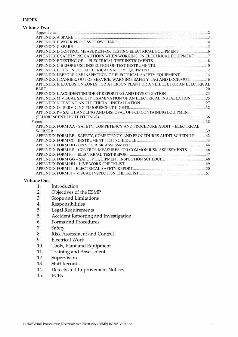
Volume Two Appendicies ......................................................................................................................................................2 APPENDIX A SPARE.....................................................................................................................................3 APPENDIX B WORK PROCESS FLOWCHART .........................................................................................4 APPENDIX C SPARE .....................................................................................................................................5 APPENDIX D CONTROL MEASURES FOR TESTING ELECTRICAL EQUIPMENT.............................6 APPENDIX E SAFETY PRECAUTIONS WHEN WORKING ON ELECTRICAL EQUIPMENT.............7 APPENDIX F TESTING OF ELECTRICAL TEST INSTRUMENTS ......................................................8 APPENDIX G BEFORE USE INSPECTION OF TEST INSTRUMENTS..................................................10 APPENDIX H TESTING OF ELECTRICAL SAFETY EQUIPMENT .......................................................12 APPENDIX I BEFORE USE INSPECTION OF ELECTRICAL SAFETY EQUIPMENT .........................14 APPENDIX J DANGER, OUT OF SERVICE, WARNING, SAFETY TAG AND LOCK-OUT................16 APPENDIX K EXCLUSION ZONES FOR A PERSON PLANT OR A VEHICLE FOR AN ELECTRICAL PART,.............................................................................................................................................................20 APPENDIX L ACCIDENT/INCIDENT REPORTING AND INVESTIGATION.......................................23 APPENDIX M VISUAL SAFETY EXAMINATION OF AN ELECTRICAL INSTALLATION...............25 APPENDIX N TESTING AN ELECTRCIAL INSTALLATION.................................................................27 APPENDIX O - SERVICING FLUORESCENT LIGHTS............................................................................32 APPENDIX P – SAFE HANDLING AND DISPOSAL OF PCB CONTAINING EQUIPMENT (FLUORESCENT LIGHT FITTINGS)..........................................................................................................36
Forms ..................................................................................................................................................................38 APPENDIX FORM AA - SAFETY, COMPETENCY AND PROCEDURE AUDIT – ELECTRICAL WORKER.......................................................................................................................................................39 APPENDIX FORM BB - SAFETY, COMPETENCY AND PROCEDURES AUDIT SCHEDULE...........42 APPENDIX FORM CC - INSTRUMENT TEST SCHEDULE ....................................................................43 APPENDIX FORM DD - ON SITE RISK ASSESSMENT ..........................................................................44 APPENDIX FORM EE – CONTROL MEASURES FOR COMMON RISK ASSESSMENTS ..................46 APPENDIX FORM FF – ELECTRICAL TEST REPORT ...........................................................................47 APPENDIX FORM GG – SAFETY EQUIPMENT INSPECTION SCHEDULE ........................................48 APPENDIX FORM HH – LIVE WORK CHECKLIST ................................................................................49 APPENDIX FORM II – ELECTRICAL SAFETY REPORT........................................................................50 APPENDIX FORM JJ – VISUAL INSPECTION CHECKLIST ..................................................................51
Volume One 1. Introduction 2. Objectives of the ESMP 3. Scope and Limitations 4. Responsibilities 5. Legal Requirements 5. Accident Reporting and Investigation 6. Forms and Procedures 7. Safety 8. Risk Assessment and Control 9. Electrical Work 10. Tools, Plant and Equipment 11. Training and Assessment 12. Supervision 13. Staff Records 14. Defects and Improvement Notices 15. PCBs

I:\H&S\H&S Procedures\Electrical\Act_Electricity\ESMPj 180205-Vol2.doc - 2 -
Appendicies

I:\H&S\H&S Procedures\Electrical\Act_Electricity\ESMPj 180205-Vol2.doc - 3 -
APPENDIX A SPARE

I:\H&S\H&S Procedures\Electrical\Act_Electricity\ESMPj 180205-Vol2.doc - 4 -
APPENDIX B WORK PROCESS FLOWCHART

I:\H&S\H&S Procedures\Electrical\Act_Electricity\ESMPj 180205-Vol2.doc - 5 -
APPENDIX C SPARE

I:\H&S\H&S Procedures\Electrical\Act_Electricity\ESMPj 180205-Vol2.doc - 6 -
APPENDIX D CONTROL MEASURES FOR TESTING ELECTRICAL EQUIPMENT
Objective: To identify control measures that may need to be implemented when testing and faultfinding on electrical equipment. Method The following control measures are commonly used safety activities and the actual control measures used will depend on the risk assessment carried out. Additional control measures should be used when this list is not appropriate. The control measure used must be recorded on the job card for that particular job. It is satisfactory to record the identification letter of the control measure on the card. If this is done a list of the control measures must be at site. Other control measure must be written in full. Control measures Remove metallic jewellery or body piercing when conducting tests; Non-flammable clothing with long sleeves and long trousers worn in high fault current situations or in a close testing environment. Insulating mat used in a close situation or when high fault currents exist; Insulating gloves used in a close situation when high fault currents exist or when the ground or surrounds are wet. Instrument checked to ensure it is suitable for prospective fault current, is in-test and the leads are in a satisfactory condition; Tools checked to ensure insulation is complete and in good condition RCD used on supply for equipment connected by a plug and socket; Barriers installed to prevent access by the general public; Live parts not involved in the testing activity covered for safety. Safety Observer is used if high fault currents exist at work site or a risk assessment identifies sufficient additional hazards. Reference Procedures: Before use inspection of electrical instruments – Appendix G The actual control measure used must be recorded on the job card for that particular job. It is satisfactory use the identification letter of the control measure.
I:\H&S\H&S Procedures\Electrical\Act_Electricity\ESMPj 180205-Vol2.doc - 7 -
APPENDIX E SAFETY PRECAUTIONS WHEN WORKING ON ELECTRICAL EQUIPMENT
Objective: To identify safety precautions that may need to be implemented when isolating fixed wired electrical equipment for the purpose of carrying out electrical work. Method When it is necessary to isolate electrical equipment for the purpose of carrying out work it is necessary to ensure that safety of all involved. This safety consideration also includes persons carrying out non-electrical work on isolated electrical equipment. The following safe precautions should be considered. Others may re relevant depending on the work situation. o Ensure the correct circuit protective device is being used to isolate supply; o Carry out electrical tests to prove the equipment has been isolated before
work commences. o Lock and tag isolating point. o Protect any live parts in the vicinity of the work site so that they cannot be
touched. o Erect barriers to protect others from work site dangers. o Conduct electrical tests following completion of electrical work o Prove equipment works satisfactorily.
Reference Procedures: Control measures for testing electrical equipment – Appendix D Before use inspection of electrical test instruments – Appendix F Safety tag and lockout – Appendix J

I:\H&S\H&S Procedures\Electrical\Act_Electricity\ESMPj 180205-Vol2.doc - 8 -
APPENDIX F TESTING OF ELECTRICAL TEST INSTRUMENTS
Objective: To identify the requirements for the regular testing of electrical test instruments to ensure they are in proper working order. Types of instruments are: Test lamps Voltmeters Portable RCD used for fault finding Insulation Resistance tester Ohmmeters Fault loop impedance tester. Resistance test block RCD timing tester. Multimeters Method Every testing instrument shall be tested on a regular basis in accordance with the listed procedure. Items that pass the test are to be tagged with the next test date and returned to service. Any item that does not pass the test is not to be used. Following repair the instrument must be tested and tagged before being returned to service. Test records shall be retained for 5 years. Whenever any tests are conducted by an external organisation a written test report will be required after the testing of each item. The testing organisation must provide written details of test methods. Test lamp Test lamps must be tested to prove they are in proper working before and after each use. They will not be tested on a six months period and will not be tagged. Voltmeter Voltmeters used to identify that voltage is present must be tested to prove they are in proper working order before and after each use. They will not be tested on a six months period and will not be tagged. Voltmeters used to measure voltage (against identifying whether voltage is present) must be checked for accuracy against a known and tested source. The item must be tagged with the next test date. Items must be checked every six months. Portable RCD used for fault finding Each instrument must be tested for current and time accuracy every six months. The recognised values are: Class 1 RCD 10 mA 40 msec Class 2 RCD 30 mA 300msec Insulation resistance tester An insulation resistance tester shall have a nominal open circuit voltage of 500vDC and shall maintain its terminal voltage within +20% and –10% of the nominal open circuit terminal voltage, when measuring a resistance of 1.0 Mohm on the 500V range. The accuracy of the instrument must be checked against the following resistors with a tolerance of 1%. Instruments shall be tested every six months.

I:\H&S\H&S Procedures\Electrical\Act_Electricity\ESMPj 180205-Vol2.doc - 9 -
0.5 ohm 1.0 ohm 2.0 ohm 20.0 ohm 10,000 ohm 1.0 megohm Ohmmeter An ohmmeter shall be capable of accurately reading in the range between 0.5 and 5 ohms. The accuracy of each ohmmeter must be checked against the following resistors with a tolerance of 1%. Instruments shall be tested every six months. 0.5 ohm 1.0 ohm 2.0 ohm 20.0 ohm Fault loop impedance tester. A fault loop impedance tester is to be tested against a known resistance source every 6 months. The instrument readings shall be within the tolerance indicated by the manufacturer. Resistance test block The resistance test block must be tested against a known source at least every 2 years. The resistance values must be within +1% to –1%. Multimeters Instruments that have multi function capabilities shall have each of the individual functions tested as in accordance with the above procedures. Each function shall be tested every six months

I:\H&S\H&S Procedures\Electrical\Act_Electricity\ESMPj 180205-Vol2.doc - 10 -
APPENDIX G BEFORE USE INSPECTION OF TEST INSTRUMENTS
Objective: To identify the checks that must be carried out before a testing instrument can be used. Types of instruments are: Test lamp; Voltmeter; Portable RCD used for fault finding; Insulation Resistance tester; Ohmmeter; Fault loop impedance tester. Multimeters Method Any item that is not in-test or does not indicate in an acceptable manner must not be used. Test lamp Test lamps must be tested to prove they are in proper working order before and after each use. Test lamps are only to be used to identify voltage when a circuit protective device of 100 amps or less protects the electrical equipment being tested. Voltmeter Voltmeters used to identify whether voltage is present shall be tested to prove they are in proper working order before and after each use. When a voltmeter is used to measure voltage (against identifying whether voltage is present) the test tag on the instrument shall be checked to ensure the instrument is in-test. Voltmeters are divided into a number of categories depending on the situation and the possible fault current that could occur at the test point. Test leads that are supplied with a particular type of instrument are not to be used on an instrument with a different category. Categories are: Installation Category 1: Relates to signal level, special equipment or parts of equipment, telecommunications, electronic and similar equipment. Installation Category 2: Relates to the local level, appliances, equipment sub circuits, portable equipment etc. This category of instrument can only be used where a protective device of 100 amps or less protects the electrical equipment. Installation Category 3: Relates to the distribution level, main switchboards etc. This category of instrument may be used on a sub/board or a main switchboard that is not supplied directly from a transformer. Installation Category 4: Relates to the primary supply level and this is the only category of instrument that is to be used to identify voltage on a main switchboard supplied directly by a transformer.

I:\H&S\H&S Procedures\Electrical\Act_Electricity\ESMPj 180205-Vol2.doc - 11 -
Only Installation Category 3 or 4 instruments are to be utilised on low voltage. Portable RCD used for fault finding Before being used the test button must be pressed to ensure the instrument is working and the test tag must be checked to ensure the instrument is in-test. Insulation Resistance tester Before use the test tag must be checked to ensure the instrument is in-test. Ohmmeter Before use the test tag must be checked to ensure the instrument is in-test. Fault loop impedance tester. Before use the test tag must be checked to ensure the instrument is in-test Multimeter Before use the test tag must be checked to ensure the instrument is in-test
I:\H&S\H&S Procedures\Electrical\Act_Electricity\ESMPj 180205-Vol2.doc - 12 -
APPENDIX H TESTING OF ELECTRICAL SAFETY EQUIPMENT
Objective: To detail the requirements for the regular testing of electrical safety equipment. Testing requirements for the following items are listed: Safety harness Ladders Insulating mats and covers Insulating gloves Low voltage rescue kit Method Each item of equipment shall be tested every six months. Items that pass the test are to be tagged with the next test date and returned to service. Any item that does not pass the test is to be removed from service. After repair an item must be tested before being returned to service. Test records shall be retained for 5 years. Whenever an item of equipment is tested by an external organisation a written test report will be required. The testing organisation will be required to provide written details of test methods. Safety harness The following components shall be individually inspected. Snap hooks An overall check for wear, distortion, corrosion and damage and a specific check of the latch and its pivot for distortion and/or breakage. A specific check of the latch return spring for breakage distortion or loss of tension. The check of the latch and its spring shall include a slow closing of the latch from the fully open position. The latch shall close fully in a smooth and positive manner. Rings For damage, distortion or cracked welds Pole straps For any damage or signs of wear, excess distortion, broken, cut or worn threads. Webbing For cuts, cracks, tears, or abrasions undue stretching and damage due to deterioration, heat, acids or other corrosives. Stitching For broken, cut or worn threads. Ladders Stiles and rungs Not cracked, splintered or loose

I:\H&S\H&S Procedures\Electrical\Act_Electricity\ESMPj 180205-Vol2.doc - 13 -
Metal parts Not cracked or bent
Moving parts No signs of excessive wear
Bolts and pins Satisfactory security
Ropes Fitted and in good order
Bucket or chain Secure and undamaged especially at fastenings to stiles
Feet Not worn or split. If movable must be able to move freely
Timber ladder No sign of decay, borers or termites
Fibreglass ladders Surface smooth, clean and polished, of uniform colour and without any pits chips voids or longitudinal grooves along the stiles.
Insulating mats and covers The item shall be washed with water and soap or detergent, stretched and examined for the following: Blisters, cracks, cuts or holes Embedded foreign matter Defective fastenings Insulating gloves Insulated gloves will be inspected by each electrical worker and replaced periodically, but at intervals no longer than every 12 months. Low voltage rescue kit A rescue kit shall contain the following equipment and be inspected every six months to ensure all items are present, items are in good condition and gloves are in-test. : Insulated crook Insulating gloves in protective cover. Gloves shall be tested every six months as required for other insulating gloves. “Isolate Here In Emergency’ sign. Burn dressings and fire blanket Torch

I:\H&S\H&S Procedures\Electrical\Act_Electricity\ESMPj 180205-Vol2.doc - 14 -
APPENDIX I BEFORE USE INSPECTION OF ELECTRICAL SAFETY EQUIPMENT
Objective: To identify the requirements for an examination of electrical safety equipment before on-site use. Items include: Safety harness Ladders Insulating mats and covers Insulating gloves Low voltage insulated tools Low voltage rescue kit Safety helmets Method Each item of equipment shall be inspected before use. The due test date shall be checked every time an item is used. Any item that has a defect or is not in-test shall be withdrawn from service, tagged as faulty and not used until repaired and/or tested. Safety harness The following components shall be individually inspected. Snap hooks An overall check for wear, distortion, corrosion and damage Specific check of the latch and its pivot for distortion and/or breakage. A specific check of the latch return spring for breakage distortion or loss of tension. The check of the latch and its spring shall include a slow closing of the latch from the fully open position. The latch shall close fully in a smooth and positive manner. Rings For damage, distortion, cracked welds Pole straps For any damage or signs of wear, excess distortion, broken, cut or worn threads. Webbing For cuts, cracks, tears, or abrasions undue stretching and damage due to deterioration, heat, acids or other corrosives. Stitching For broken, cut or worn threads. Ladders
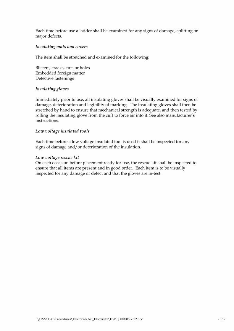
I:\H&S\H&S Procedures\Electrical\Act_Electricity\ESMPj 180205-Vol2.doc - 15 -
Each time before use a ladder shall be examined for any signs of damage, splitting or major defects. Insulating mats and covers The item shall be stretched and examined for the following: Blisters, cracks, cuts or holes Embedded foreign matter Defective fastenings Insulating gloves Immediately prior to use, all insulating gloves shall be visually examined for signs of damage, deterioration and legibility of marking. The insulating gloves shall then be stretched by hand to ensure that mechanical strength is adequate, and then tested by rolling the insulating glove from the cuff to force air into it. See also manufacturer’s instructions. Low voltage insulated tools Each time before a low voltage insulated tool is used it shall be inspected for any signs of damage and/or deterioration of the insulation. Low voltage rescue kit On each occasion before placement ready for use, the rescue kit shall be inspected to ensure that all items are present and in good order. Each item is to be visually inspected for any damage or defect and that the gloves are in-test.

I:\H&S\H&S Procedures\Electrical\Act_Electricity\ESMPj 180205-Vol2.doc - 16 -
APPENDIX J DANGER, OUT OF SERVICE, WARNING, SAFETY TAG AND LOCK-OUT
Objective: To identify the safety precautions to be implemented when hard wired electrical equipment is isolated prior to electrical work being carried. Method To maintain the electrical safety of persons working on fix wired electrical equipment it is necessary to ensure that the equipment cannot be accidentally energised while work is being carried out. This is not only a common sense safety requirement but it is also included in the Electricity Safety Regulation 2002. Legislation Regulation (20) stipulates that if an electrical worker has isolated an item of equipment (by switch or fuse) and while the worker is performing the work, the worker does not have the isolation point under the worker’s sole effective control. The electrical worker must ensure: That there is attached to the device, in a prominent position, a company supplied warning sign and; The isolation point, when in the open position, is locked; or other precautions are taken to stop the device being accidentally closed. Personal Safety Isolation can be achieved by methods or systems using locks, rendering the mechanism inoperable, a combination of these or by another equally safe method. In situations where other people can access isolation points, it is important that the isolation method or system cannot be inadvertently or easily compromised. Before any electrical work is performed on isolated equipment, a test to ensure that the equipment has been positively isolated must be carried out. The below Lock Out Steps may be utilised for locking out electrical energy as well as other energy sources
I:\H&S\H&S Procedures\Electrical\Act_Electricity\ESMPj 180205-Vol2.doc - 17 -
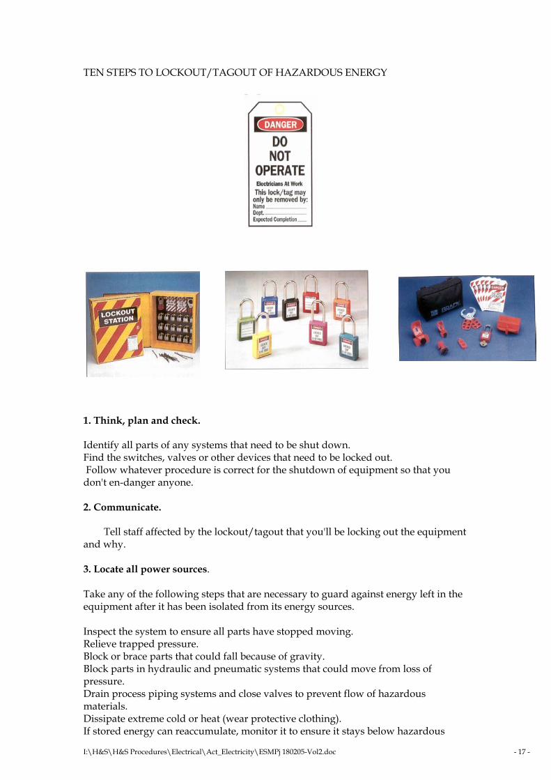
TEN STEPS TO LOCKOUT/TAGOUT OF HAZARDOUS ENERGY
1. Think, plan and check. Identify all parts of any systems that need to be shut down. Find the switches, valves or other devices that need to be locked out. Follow whatever procedure is correct for the shutdown of equipment so that you don't en-danger anyone. 2. Communicate. Tell staff affected by the lockout/tagout that you'll be locking out the equipment and why. 3. Locate all power sources. Take any of the following steps that are necessary to guard against energy left in the equipment after it has been isolated from its energy sources. Inspect the system to ensure all parts have stopped moving. Relieve trapped pressure. Block or brace parts that could fall because of gravity. Block parts in hydraulic and pneumatic systems that could move from loss of pressure. Drain process piping systems and close valves to prevent flow of hazardous materials. Dissipate extreme cold or heat (wear protective clothing). If stored energy can reaccumulate, monitor it to ensure it stays below hazardous

I:\H&S\H&S Procedures\Electrical\Act_Electricity\ESMPj 180205-Vol2.doc - 18 -
levels. 4. Neutralize all power at its source. Be sure to isolate all energy sources of main and secondary power supplies. Disconnect electricity. Never remove a fuse instead of disconnecting. Block moveable parts. Drain or bleed hydraulic or pneumatic lines. Lower suspended parts to rest position. 5. Lock out all power sources. Use a lock designed only for this purpose. Each worker should have a personal lock. Fill tags out completely and correctly. 6. Verify all equipment is isolated. Make sure all danger areas are clear of personnel. Verify that the main disconnect switch or circuit breaker cannot be moved to the 'on' position. Use a voltmeter or other equipment to check the switch. Press all start buttons and other activating controls on the equipment itself to ensure the power doesn't go on. Shut off all machine controls when the testing is finished. 7. Turn controls back to "off". Perform necessary repairs or maintenance. Look ahead and avoid doing anything that could re-activate the equipment. Don't bypass the lockout when putting in new piping or wiring. 8. Removing lockout/tagout After maintenance is finished, and before restarting equipment: Remove tools from the work area. Reinstall machine guards. Ensure workers are a safe distance away while restoring energy. Notify everyone who works in the area that lockout/tagout is being removed. Remove the lockout/tagout devices. Except in emergencies, each device must be removed by the person who put it on. 9. During a lockout/tagout situation Never remove a lock without authorization. Never turn on a machine during a lockout. Never operate a machine that has been tagged. Stay clear of locked or tagged machinery until you are notified that the power is back on.

I:\H&S\H&S Procedures\Electrical\Act_Electricity\ESMPj 180205-Vol2.doc - 19 -
10. After a lockout, Ensure all guards are back in place before operating equipment and all tools are removed from the machinery. Never bypass a lockout or let a colleague do so. Special Situations If you must temporarily reactivate equipment you are working on: Remove unnecessary tools from the work area and ensure everyone is clear from the equipment. Remove the lockout/tagout devices and re-energize the system As soon as the energy is no longer needed, isolate the equipment and re-apply lockout/tagout. If servicing lasts more than one work shift, lockout/tagout protection must not be interrupted. When the person who applied a lock isn't there to remove it, the lock can be removed only in an emergency, and only under the direction of the foreman The lock must not be cut unless a foreperson is present. Never remove the lock without making sure it is absolutely safe.

I:\H&S\H&S Procedures\Electrical\Act_Electricity\ESMPj 180205-Vol2.doc - 20 -
APPENDIX K EXCLUSION ZONES FOR A PERSON PLANT OR A VEHICLE FOR AN ELECTRICAL PART,
Objective: To specify the legal clearances and conditions that must be complied with when working in the vicinity of electrical parts or overhead lines Method There are specific clearances that must be maintained when working in the vicinity of electrical parts or overhead lines. Clearances for a particular person will depend on the training and authorisation of that person. Definitions Authorised person, for an electrical part, means a person who: Has enough technical knowledge and experience to do work that involves contact with, or being near to, the electrical part; and Has been approved by the person in control of the electrical part to do work that involves contact with, or being near to, the electrical part, or is authorised to act for the person in control of the electrical part. Instructed person for an electrical part means a person who is acting under the supervision of an authorised person for the electrical part. Untrained person for an electrical part means a person who is not an authorised person or an instructed person for the electrical part Electrical part means an exposed part; or an overhead insulated electric line. Work means work of any type, whether or not electrical work, other than live work or electrical welding performed in accordance with a safe system of work. The exclusion zone, for a person for an electrical part, or for operating plant or a vehicle for an electrical part, means the distance from the part stated for the person, plant or vehicle in the table. For applying the table to a person, the person includes any article of clothing worn by the person, and any conductive object the person is holding or carrying. For applying the table to operating plant, the operating plant includes anything the operating plant is handling (carrying, connected to whether or not temporarily, controlling, holding, and lifting). For applying the table to a vehicle, the vehicle includes anything the vehicle is carrying or otherwise handling. For applying the table to operating plant operated by an authorised person or instructed person who does not have a safety observer, the authorised person or instructed person must be taken to be an untrained person. Safety Observer If it is possible that any part or person on a crane or operating plant (EWP included) could enter the exclusion zone of live electric lines during operation, it is necessary for a safety observer to be present. The following conditions apply to the safety observer:

I:\H&S\H&S Procedures\Electrical\Act_Electricity\ESMPj 180205-Vol2.doc - 21 -
The safety observer should not be required to carry out any other duty at the time. The safety observer should be able to communicate effectively with the operator of the crane or plant at all times. The safety observer should not be required to observe more than one crane or plant at a time. The safety observer should be trained to perform the role. The safety observer should mark the border of the exclusion zone with suitable markers e.g. red warning tapes, which can be easily viewed by the crane operator. The safety observer observing an item of plant near an exclusion zone is not required to be proficient in CPR or rescue. The person must be competent to understand the work and have the authority to stop the item of plant if it encroaches into the exclusion zone. If an approved person makes contact with an energized line it is necessary for a safety observer to be present. In this case the safety observer should be competent in CPR and rescue. Becoming an authorised person The person in control of the aerial line approves an authorised person. If the line is owned by a distribution entity it is necessary to contact the relevant distributor for approval. If the aerial line is a private line then the owner becomes the person in control who can approve the authorised person. When working in the vicinity of a private line the contractor would normally be an authorised person without further correspondence. It is the responsibility of the contractor to ensure that relevant staff are competent to carry out the work. Consultation with a distribution entity requires contacting the entity and being provided with safety information within 7 days. In the case of a private installation, advice to the customer would satisfy consultation. All work must then be completed safely.
I:\H&S\H&S Procedures\Electrical\Act_Electricity\ESMPj 180205-Vol2.doc - 22 -
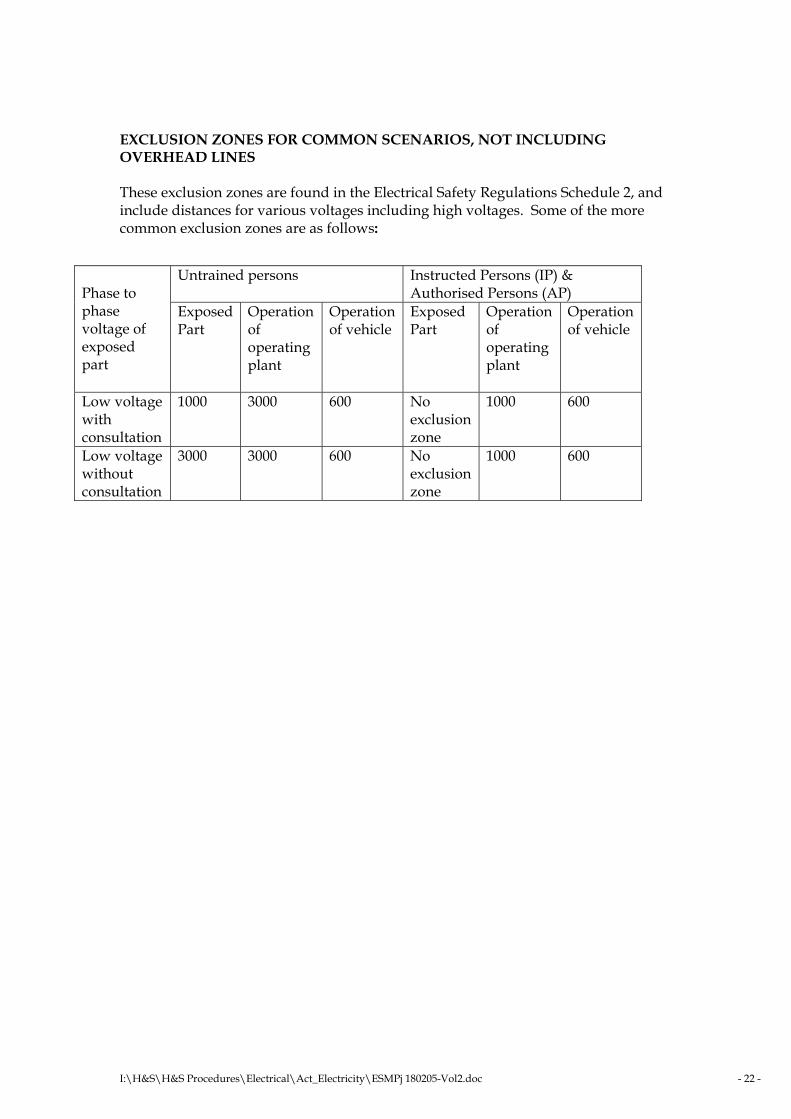
EXCLUSION ZONES FOR COMMON SCENARIOS, NOT INCLUDING OVERHEAD LINES These exclusion zones are found in the Electrical Safety Regulations Schedule 2, and include distances for various voltages including high voltages. Some of the more common exclusion zones are as follows:
Untrained persons Instructed Persons (IP) & Authorised Persons (AP)
Phase to phase voltage of exposed part
Exposed Part
Operation of operating plant
Operation of vehicle
Exposed Part
Operation of operating plant
Operation of vehicle
Low voltage with consultation
1000 3000
600 No exclusion zone
1000
600
Low voltage without consultation
3000 3000 600 No exclusion zone
1000 600
I:\H&S\H&S Procedures\Electrical\Act_Electricity\ESMPj 180205-Vol2.doc - 23 -
APPENDIX L ACCIDENT/INCIDENT REPORTING AND INVESTIGATION
Objective: To detail the requirements for the reporting and investigation of electrical accidents and incidents. When an accident involving staff students, contractors, or members of the public occurs the following procedure will be followed:
Reporting of incidents
Reporting all safety problems, incidents and accidents in your area is important for the safety and wellbeing of everyone at QUT. The Safety Problem Report and Investigation Form at http://www.hrd.qut.edu.au/healthsafety/healthsafe/hsaccincsaferep.jsp has been developed to satisfy legal reporting requirements and to capture the information which your Health and Safety Committee can use to best plan risk management strategies in your work area.
All cases of serious work-related injury, work-caused illness or dangerous event must be reported to HR Health and Safety Advisory Services by telephone on the day and notified on a Safety Problem Report and Investigation Form within three working days (see the Human Resources Health and Safety Advisory Services website).
Ambulance assistance
If an ambulance is needed for a serious injury or medical emergency, then dial the 24 hour Emergency Security Number (Ext 5555 or 3864 5555). Briefly explain the circumstances and location to the Security Officer who will initiate the proper procedures, notify the Queensland Ambulance Service (QAS) and provide an escort to the exact location on the correct campus Definitions A “serious electrical incident” is an incident involving electrical equipment if, in the incident— A person is killed by electricity; or A person receives a shock or injury from electricity, and is treated for the shock or injury by or under the supervision of a doctor; or A person receives a shock or injury from electricity at high voltage, whether or not the person is treated for the shock or injury by or under the supervision of a doctor. A “dangerous electrical event” is defined in section 12 of the Electrical Safety Act 2002. A number of situations that constitute a dangerous electrical event are: An event that involves electrical equipment and in which significant property damage is caused directly by electricity or originates from electricity; The performance of electrical work by a person not authorized under an electrical work licence to perform the work; The performance of electrical work by a person if, as a result of the performance of the work, a person or property is not electrically safe; The discovery by a licensed electrical worker of electrical equipment that has not been marked as required under this Act. If a serious electrical incident or dangerous electrical event happens it is necessary to:

I:\H&S\H&S Procedures\Electrical\Act_Electricity\ESMPj 180205-Vol2.doc - 24 -
Give written notice of the incident or event to the ESO in the approved form (Incident Notification Form – Form 3 obtainable from the ESO website) and Ensure the written notice is received by the ESO within 24 hours after becoming aware of the incident or event. If the incident is a serious electrical incident in which a person has been killed, it is necessary to advise, by phone, fax or another suitable form of immediate and effective communication, the ESO immediately after becoming aware of the incident, Within three days make a record of the event on a Form 3. If the person is incapacitated by the event complete the form as soon as reasonably practicable after the person is no longer incapacitated. Keep records for three years. Not disturb the scene until an inspector completes an investigation.
When a ‘serious electrical incident’ or ‘dangerous electrical event’ occurs, discuss with the Health & Safety Advisory Services Section as to whom will advise the ESO of the accident on the appropriate forms in accordance with this procedure.
I:\H&S\H&S Procedures\Electrical\Act_Electricity\ESMPj 180205-Vol2.doc - 25 -
APPENDIX M VISUAL SAFETY EXAMINATION OF AN ELECTRICAL INSTALLATION
Objective: To identify the steps to be taken when performing a safety examination of an electrical installation. This may be required in conducting audits of works carried out by in-house or external electrical workers to gauge work standard, and/or when concern has been raised about standard of work. Method The objective of conducting a safety examination is to ensure that the installation is electrically safe and that as far as can be seen the installation complies with the intent of the present wiring rules or basically complies with the wiring rules that were probably current when the installation was built. All defects are to be listed on the report. Where it is considered that any defect could be considered dangerous. A visual examination could also include a safety check of appliances and leads if requested by the customer. A safety examination does not guarantee that appliances and equipment will work correctly A visual examination would not normally require the disconnection of power. Appendix Form JJ - Visual Inspection Checklist will be used for recording results. A written report is to be provided to the customer even when no defects have been identified. Appendix Form II – Electrical Safety Report is to be used. Clauses are from AS/NZS 3000 unless indicated otherwise. Procedure Visually check service clearance across fence line and drive to determine whether there is satisfactory clearance for vehicles (3.7m at fence alignment, 4.5m over driveways, 2.7m areas not normally used by vehicles) Check at the point of attachment to determine whether any exposed cables appear to have deteriorated from the effects of sunlight. Check the location and arrangement of all switchboards with respect to mechanical damage, hazardous and restricted locations, exposed cables, access to live cables without the use of a tool, etc. Ensure the MEN is intact and is a good connection. Make sure the connections are tight and that there are no soldered joints under screws. Inspect any earth electrode and the associated main earth; ensure there is a connection to the earth. If the earth is connected to an underground water pipe, recommended an earth stake be installed. Inspect any visible circuit earths and joints. Check that any poles of aerial lines are in good condition. Ensure the ground clearance of aerial cables is adequate and the cables are in satisfactory condition. (Table 3.8)
I:\H&S\H&S Procedures\Electrical\Act_Electricity\ESMPj 180205-Vol2.doc - 26 -
Aerial cables must be insulated 2m from connection to a building. Check accessible areas of roof spaces and other areas for cables that may be subject to damage (Clause 3.9.4 and 3.9.5). An RCD is suitable protection for cables. Assess cables and for possible derating if they are partially or totally surrounded by thermal insulation or flammable material. (AS/NZS3008 clause 3.4.3) Check downlights to ensure there is adequate clearance from thermal insulation. (25mm for lv and 50 for elv Clause 4.3.6.3). Check fixing and support of equipment is adequate and that item is suitable for the location eg equipment exposed to weather must have a suitable IP rating. (AS 1939) Check every room, separate areas and outbuildings to ensure the following are or appear to be in good condition. Some outlets may be hidden. Every effort should be made to check all outlets. A torch may be necessary. Switches. All outlets Luminaries. Ceiling fans and controllers Permanently connected appliances and hot water systems. External equipment subject to the weather has an appropriate IP rating. Pool and outside equipment. Measure clearance distances from water containers in bathrooms and laundries. Test that any upright stove is stable and cannot tilt. It may need anti-tilt brackets. Check protection devices at the switchboard are sized to protect the cable and that fuses have the correct size element. Check as to whether RCD’s are installed on light and power circuits, and make recommendations accordingly. Ensure the trip button on RCD’s works properly and within the correct time. Check switchboard markings are adequate. Ensure that a correct method of earthing is being used where sub-boards are at the installation. Include outbuildings in the examination. Check that a correct method of earthing is being used when an outbuilding has a distribution board. Examine the suitability of pool equipment within the pool zone and the existence of RCDs. If it is not possible to obtain entry to a room or area or outlets cannot be viewed because of furniture the details should be detailed on the report form.

I:\H&S\H&S Procedures\Electrical\Act_Electricity\ESMPj 180205-Vol2.doc - 27 -
APPENDIX N TESTING AN ELECTRCIAL INSTALLATION
Objective: To detail the electrical tests that must be completed before electrical work can be connected to supply. Method If it is necessary to conduct a visual examination of the installation then Procedure Appendix M - Visual Safety Examination will be used. Electrical tests results are to be recorded on Appendix Form FF – Electrical Test Record. If it is necessary to provide a written report to the customer, Appendix Form II – Electrical Safety Report will be used. This testing procedure is derived from AS/NZS 3000 and AS/NZS 3017. It has been arranged so that testing and checking may be carried out in a logical and orderly manner. However, it is acceptable to vary the written procedure providing the same results are achieved the intent of the procedure is satisfied and the installation is electrically safe. The inspection process should be “results orientated” and not necessarily procedural orientated. Testing Procedures This testing procedure can be used for the testing of new installations or fore a full electrical test on an existing installation. Advise the customer that it is necessary to disconnect all supply for a short period of time. Ensure testing instruments are currently in test and that tools are in good condition. Note the position of protective devices as to whether any were isolated. Leave installation in condition as it was found. If supply is connected isolate supply at the service fuse. Disconnect any earth bond to the neutral on an aerial supply. Earthing Continuity A bonding or equipotential conductor is to ensure all metal is at the same potential. An earthing conductor carries any return or fault current. Remove the main earthing conductor and the main neutral conductor, from the neutral link. Where practicable, disconnect any earth bond conductor (eg. water heater earth). Test continuity of the main earthing conductor between the electrode, adjacent to the main earth connection, and the main switchboard. Maximum Resistance 0.5 ohm. Test continuity between the main earthing conductor at the switchboard and any portion of metallic water piping required to be bonded i.e. any copper water pipe leaving the ground and entering the building. Maximum Resistance 0.5 ohms

I:\H&S\H&S Procedures\Electrical\Act_Electricity\ESMPj 180205-Vol2.doc - 28 -
Test continuity between the main earthing conductor at the switchboard and all accessories and permanently connected appliances that are required to be earthed, eg, HWS, socket outlets, lights, motors, range etc. Maximum resistance shall be low enough to allow permit the passage of current necessary to operate the circuit protective device or 2 ohms whichever is the lesser. Reconnect any earth bonds that were disconnected. NOTE: If insulation resistance tests are carried out before continuity tests a defective continuity test may require a further insulation resistance test of the circuit affected. Insulation Resistance Test insulation resistance between the main earthing conductor at the switchboard and each conductor of the consumers mains. Minimum Insulation Resistance 1 Megohm. Test insulation resistance between the main earthing conductor at the switchboard and the neutral link, and terminals of the main switch/s. Minimum Insulation Resistance for the general installation is I megohm and for appliances incorporating heating elements it is .01 Megohms. Where circuits with low insulation resistance incorporate appliances, the appliances are to be disconnected where practical and the test repeated on the circuit to establish whether the equipment or the circuit has the low insulation resistance. Test insulation resistance between active and neutral conductors of consumers mains (between phases if three phase), submains and final sub circuits. Ensure that parallel conductors have no interconnection. Minimum Insulation Resistance 1 Megohm. Test insulation resistance between any conductive parts of low pitched roofs or roofs associated with cathedral ceilings and the main neutral link and the terminals of the main switch/s. Minimum Insulation Resistance 1 Megohm. Polarity Testing of Mains Turn OFF the main switch/s and any circuit breakers or remove all fuse carriers. Confirm that bonding conductor to a service support is not connected and that main neutral is still disconnected from link. Reconnect supply. Test between the main neutral conductor and the line terminal/s of the main switch/s and on a multiphase installation, between phases. The test lamps should light, proving that the test lamps are in order and that the required supply is available.
I:\H&S\H&S Procedures\Electrical\Act_Electricity\ESMPj 180205-Vol2.doc - 29 -
Test between the main neutral conductor and an independent earth electrode. The test lamps should not light. Test between an independent earth electrode and the line terminal/s of main switch/s. The test lamps should light. NOTE: Failure of the test lamps to light during this test indicates that the resistance between the independent electrode and the general mass of earth is too high. The last two tests must be repeated using an approved instrument (voltmeter) in lieu of test lamps. Test between the main neutral conductor and both line and load side of all circuit protective devices. The test lamps should not light, proving there is no supply at the circuit protective devices with the main switch/s in the "OFF" position. Replace the main neutral conductor and main earthing conductor into the neutral link. Turn the main switch ON. NOTE: A similar polarity test sequence is required for submains. NOTE: Replacement of the main earth and neutral into the neutral link at this time is to minimise the possibility of a potential rise on the earthing system during tests and causing others on site to receive a shock. Test between the main neutral conductor and the line side of all circuit protective devices (CPDs). (Proves supply at CPDs). Test between the phases of circuit protective devices on a multiphase installation. Test between the main neutral conductor and the load side of any circuit breakers. Test lamps should not light proving the CBs turn off. Reinstate any service bonding conductor that was removed. Testing and checking of circuits Water Heater Energise circuit. Check that the control switch, over temperature cutout, and thermostat are connected in the active conductor. Check that the neutral conductor corresponds with the active conductor and that there is no interconnection with other circuits. Check access is available for component replacement and maintenance. Check circuit loading and that the current carrying capacity of the cable, control switch, and protection device has not been exceeded and the switchboard is correctly marked.

I:\H&S\H&S Procedures\Electrical\Act_Electricity\ESMPj 180205-Vol2.doc - 30 -
For water heaters with off peak and booster elements that have a common neutral, a double pole control switch or double pole circuit breaker is required. Range/Cooking Appliance Ensure that any isolating switch and all range element control switches are in the "OFF" position. Note kW rating of range, and check that the current carrying capacity of all cables and equipment forming part of the final subcircuit for the range has not been exceeded. Connect supply and prove that any isolating switch is connected in the active conductor and effectively isolates supply. If fuses are incorporated in the range prove they are connected in the active conductor. Check that the neutral conductor corresponds with the active and that there is no interconnection with other circuits. Power Circuits Energise and test one circuit at a time, checking each outlet individually for continuity polarisation and polarity. Energise the RCD/s and test for accuracy with an RCD test instrument. The RCD/s should trip between 50% and 100% of rated value. Energise all applicable circuits and press any RCD test button to ensure it is operational. Check cable rating, RCD current and trip rating, fuse element or circuit breaker size and switchboard marking. Lighting Circuits Energise each lighting circuit separately. Check that each light works. Test light switches for correct polarity Energise any RCD/s and test for accuracy with an RCD test instrument. The RCD/s should trip between 50% and 100% of rated value. Check cable rating, fuse element or circuit breaker size and switchboard marking. Permanently Connected Appliances or Equipment Energise each circuit separately. Check the circuit protection device does not exceed the current carrying capacity of the conductor. Energise any RCD/s that may be associated with permanently connected appliances (eg. pool equipment) and test for accuracy with an RCD test instrument. The RCD/s

I:\H&S\H&S Procedures\Electrical\Act_Electricity\ESMPj 180205-Vol2.doc - 31 -
should trip between 50% and 100% of rated value. VISUAL If the installation is new a visual check of the installation should be made to ensure that the work is complete and that all cables are terminated. GENERAL Using total loading obtained from previous tests, calculate the maximum demand and check that the rating of the consumers mains and main switch are suitable. Measure voltage at the extremity of any power circuit to ensure it is satisfactory and is greater than 215. If voltage is less than this figure recommend to the customer that they request the electricity distributor to conduct a voltage check at their terminals. Check marking and rating of main switch/s is correct and refit neutral link cover where required. Test with the whole of the installation energised, including lighting points switched ON, that any exposed conductive parts are not live. Ensure any fridge, freezer or hot water system is energised and stove elements and oven are off. Before leaving the site check that the switchboard is in the same condition as it was found. Ensure any fridges or deep freezes are on any hot plate elements are off. RECHECK THE MEN CONNECTIONS

I:\H&S\H&S Procedures\Electrical\Act_Electricity\ESMPj 180205-Vol2.doc - 32 -
APPENDIX O - SERVICING FLUORESCENT LIGHTS
Objective: To describe the correct procedures to follow when replacing fluorescent lamps and starters competently and safely. PERSONAL PROTECTIVE EQUIPMENT Long sleeve shirts (cotton) Rubber sole shoes (closed in) Safety glasses (supplied) MATERIALS/EQUIPMENT REQUIRED Various sizes of timber and/or fibreglass stepladders: 1.8 m, 2.4 m. Danger tags, cleaning brush, rags. Small stock of various size tubes. Starters. PREPARATION AND SAFETY ADVICE Obtain permission from the occupant of the room/department to work on the fitting. Inspect the fitting and ascertain the equipment/materials required. Set up the ladder below the light fitting to be worked on making sure that it is in the fully spread position, and positioned so that you can work off it comfortably and safely. Where areas are not accessible by stepladder report situation to the electrician in charge. Note: Never use the top of the ladder as a step or tread, the second tread from the top is as far as you should go on a stepladder. Read important guide (attached) on Safe Use of Ladders. Switch off light fittings before working on them. CAUTION: WORKING ON LIGHTS WITH THE POWER ON IS NOT ALLOWED. Care should be taken however to avoid contact with the bare pins of the tube and lampholders and all fittings should be treated as if there is power connected to them. DIFFUSER REMOVAL/REPLACEMENT Switch the fitting off. Don safety glasses. When removing diffusers, prevent dust and dirt from falling into the eyes, onto the floor and equipment Diffusers are made from materials such as acrylic, glass and metal and various methods of support are employed: wrap-around channelling, concealed spring latches, snap or screwed on end caps, hinged support frames, etc. Following instruction/demonstration from electrician in charge remove the diffuser to an area where it can be cleaned, using the brush or rags. When re-installing the diffuser take care not to bump the tubes out of position in the lampholders, as starting problems may result. Check that the diffuser is properly fitted and is secure. FLOURESCENT LAMP REMOVAL/REPLACEMENT

I:\H&S\H&S Procedures\Electrical\Act_Electricity\ESMPj 180205-Vol2.doc - 33 -
Switch the fitting off. Hold the tube between the lampholders with the fingers and rotate 90o at the same time apply slight downward pressure. The tube will disengage from the lampholders when the contact pins on the ends of the tube are in the vertical position. Remove the tube and lay it down in a convenient area safe from breakage (prevent it from rolling or falling ) or place in wheelie bin provided. To install the new tube, line it up horizontally between the lampholders, engage the end pins of the tube into the slots of the lampholders and with a slight upward pressure rotate the tube 90o until it “holds” in the correct position. (Reversal of the removal procedure). If the tube fails to light up when the fitting is switched on, then switch the fitting off again and rotate the tube slightly to achieve correct engagement in the lampholders., then recheck. STARTER REMOVAL/REPLACEMENT Switch the fitting off. On most fittings the starter is located on the side of the fitting or just below the fluorescent tubes. CAUTION: Some light fittings have the starters installed internally and require tools for access. If this is the case do not proceed. Inform electrician in charge for direction. THIS WORK SHOULD ONLY BE CARRIED OUT BY AN ELECTRICIAN. Hold the starter and turn it anti-clockwise until it disengages from the starter holders. Following instruction/demonstration from electrician in charge discard it to wheelie bin and install a new one of the same wattage, eg. Philip’s S10-4-65watt, Philip’s S2-4-22 watt. If the plastic protective cover comes loose leaving the inner parts of the starter exposed, DO NOT TOUCH BUT REFER IT TO A QUALIFIED ELECTRICIAN. Note: Some starters require turning clockwise for removal. Some fittings will not operate if incorrect wattage of starter is installed. Twin 18 watt light fittings require Series Connection starters, Universal 4-65 watt starters are not suitable. Use Philips P2-20 watt type. TESTING AND FAULT DIAGNOSIS Switch the fitting on. Check if all “tubes” light up. Failure to light up may indicate several faults DO NOT PROCEED FURTHER contact electrician in charge for direction. DO NOT work on a light fitting if it is in an unsafe condition, eg. fitting hanging off the ceiling, wires are exposed or any other obviously dangerous situations. REPORT TO ELECTRICIAN IN CHARGE. ATTENTION: The information contained herein attempts to acquaint the “NOVICE” tubechanger with most of the situations which may be encountered, if in any doubt do not proceed further and contact the electrician in charge for direction. LADDER SAFETY The purpose of the following is to emphasise the important points which are too

I:\H&S\H&S Procedures\Electrical\Act_Electricity\ESMPj 180205-Vol2.doc - 34 -
frequently overlooked when using ladders. The ladder should be placed on a firm and level footing. Hips between rails should be your safety rule when you reach out from a ladder. Never reach more than an arm’s length and hold on with the other hand, preferably to something other than the ladder so you won’t slip sideways. If a ladder is to be used at a doorway, the door should be blocked open, locked or guarded. When standing or moving on a ladder, face it and have at least one hand (preferably two) free to grip the ladder. One person only should normally be on a ladder. Step ladders should only be used in the fully spread position. The second tread from the top is as far as you should go on a step ladder. NEVER use the top as a step or tread. Ladders should be maintained in good condition, nuts and bolts tightened, pulleys lubricated and fraying ropes replaced.

I:\H&S\H&S Procedures\Electrical\Act_Electricity\ESMPj 180205-Vol2.doc - 35 -
Fluorescent Tube Changing Check List General Hand out registration form. Hand out paper work – must read. What we are doing – where, date & times. Show tubes, starters, two types of lamp holders, how they fit, fragile. Safety ladder video and fluro change instruction/demonstration. Never change tubes with power on. Instruct and demonstrate Test/confirm student ability PPE safety glasses MUST be worn (supplied) Boots and shoes only, no sandals. Suitable clothing, long sleeve cotton shirts, closed in rubber sole shoes. Only use fibreglass ladders (supplied). If in any doubt, ask. Step ladders Use only in fully open position, on an even surface. Never stand on top step of ladder. If working in a doorway, prop door open. If not possible to do this, have a second person guarding doorway. Always put ladder directly under job, do not stretch sideways.
I:\H&S\H&S Procedures\Electrical\Act_Electricity\ESMPj 180205-Vol2.doc - 36 -
APPENDIX P – SAFE HANDLING AND DISPOSAL OF PCB CONTAINING EQUIPMENT (FLUORESCENT LIGHT FITTINGS)
Objective: To describe the correct procedures to follow when replacing capacitors containing or that may contain PCB and disposing of them safely. For identification of PCB – Containing Capacitors please refer to information booklet for electricians and electrical contractors – Identification of PCB-Containing Capacitors – 1997 ANZECC page 4 item 3 entitled Identification of PCB-Containing Equipment. Note: Ducon capacitors have a 4 digit date on their capacitors. The first two digits represent the week of manufacture and the final two digits the year of manufacture. Therefore ‘2573’ represents the 25th week of 1973. Handling Procedure Small quantities of PCBs are usually found in sealed containers known as capacitors. PCB-containing capacitors are unlikely to pose a health risk, unless they become damaged and leak. Care must be taken when handling a damaged capacitor to ensure that spillage does not occur. The person handling the damaged capacitor should take the following precautions: Put on personal protective equipment, safety goggles and clothing before removing damaged capacitors; If capacitors are obviously leaking, wear gloves that are made of materials that are resistant to PCBs, such as Viton, polyethylene, polyvinyl alcohol (PVA), polytetrafluoroethylene (PTFE), butyl rubber, nitrile rubber, or neoprene. Mid-arm length gauntlets may be required; DO NOT use gloves made of polyvinyl chloride (PVC) or natural rubber (latex). Use disposable gloves. When working with overhead equipment (eg. Fluorescent light fixtures), wear a full face shield and appropriate hair protection; Wash any non-disposable contaminated equipment with kerosene and collect the kerosene for disposal as a PCB- contaminated solvent; If PCB vapours are suspected (eg. PCB leaks onto a hot surface in a confined space), wear a suitable respirator. Use a twin cartridge type respirator suitable for chlorinated vapours. It is always prudent to ensure adequate ventilation. NOTE: PCBs do not vaporise readily at room temperature; Do not smoke; and After handling PCBs, even if gloves were worn, wash hands well in warm, soapy water before eating, drinking, smoking, handling food or drink, or using toilet facilities. First Aid

I:\H&S\H&S Procedures\Electrical\Act_Electricity\ESMPj 180205-Vol2.doc - 37 -
If PCB contacts the eyes, immediately wash it out with copious amounts of running water for at least 10 minutes. Occasionally lift the upper and lower eye lids to ensure complete irrigation of the eye. Obtain medical attention immediately. If PCB contact the skin, immediately remove all contaminated clothing. Wash the affected areas with warm, soapy water. Do not use kerosene to remove PCB from your skin or clothing. Obtain medical attention as soon as possible. PCB spills should be handled by first evacuation people not involved with the clean-up from the spill area. Everyone involved with the clean-up needs to take the precautions listed above in the handling procedures. Clean-Up of Leaks The procedure detailed below should be followed if any PCB leaks from capacitors, or if PCB-contaminated material, such as kerosene, is accidentally spilt. Use an absorbent material (preferably commercial absorbent, kitty litter or a diatomaceous earth) to form a barrier to prevent any of the PCB from escaping into drainage systems or into the watercourse. Soak up the PCB with the absorbent material used to form the barrier. Non-porous surfaces should be cleaned with an organic solvent, for example, kerosene, and the solvent collected and disposed of as a PCB-containing solvent. All porous disposal clothing and the damaged capacitor which has been contaminated must be placed in a strong, sealed polyethylene bag, which is then to be placed in a sound, sealable metal drum. An absorbent material should be packed around the PCB equipment to absorb any leaks. The drum should then be sealed. Any PCB-contained solvents from the clean-up must be stored in separate drums. All drums must be adequately labelled ‘PCB Waste’ together with the name of the equipment or material contained within each drum. For QUT Staff, these drums should be disposed through QUT’s chemical disposal process. Contact Eric Martinez E Block GP Extension 1357. Contractors should dispose of the drums in accordance with the requirements of the Environmental Protection Agency and other appropriate authorities.

I:\H&S\H&S Procedures\Electrical\Act_Electricity\ESMPj 180205-Vol2.doc - 38 -
Forms
(TO BE READ IN CONJUNCTION WITH RELEVANT PROCEDURES)

I:\H&S\H&S Procedures\Electrical\Act_Electricity\ESMPj 180205-Vol2.doc - 39 -
APPENDIX FORM AA - SAFETY, COMPETENCY AND PROCEDURE AUDIT – ELECTRICAL WORKER
Electrical Worker: ……………….. Electrical Licence Type/Categories: ………………………. Certificates and licences checked Yes No Current N/A Current electrical licence Cabling licence Smart wiring licence Can Produce Standards/Documents/Forms
Yes No N/A Current
AS/NZS 3000 – 2000 with amendments AS/NZS 3008.1.1 – 1998 Electrical Safety Management Plan Testing Record QUT Electrical Safety Policy Electrical Safety Act 2002 Electrical Safety Regulation 2002 Code of Practice – Electrical Work
Tools and equipment available
Yes No In-Test N/A
Voltage identification equipment – suitable class for work activity
Insulation and Continuity tester. Trailing lead with resistance marked Low reading ohmmeter Proximity tester/Test Pencil Clip on ammeter Voltmeter RCD Tester RCD used for testing purposes. Fault Loop Impedance Tester Class 00 insulating gloves Non conducting Step ladder Non conducting Extension ladder Overalls with non metallic buttons Lock out tags available

I:\H&S\H&S Procedures\Electrical\Act_Electricity\ESMPj 180205-Vol2.doc - 40 -
Risk assessment including testing and fault finding
Yes No N/A
Were risks correctly identified at site Was the risk assessment adequately recorded on the work order.
Were control measures correctly implemented. Were non electrical risks considered
Safety
Yes No N/A
Test to prove isolation before touching Correct personal safety equipment used Control measures identified in risk assessment implemented
Proper care taken when using hazardous substances
Adequate protective clothing worn Eye protection worn Ear protection worn Metallic jewellery removed when working live Safety footwear worn Protective headwear worn Adequate protection against sun Equipment safety and lockout procedures implemented.
Adequate protection for the public at the worksite All extension leads and portable tools tested and tagged.

I:\H&S\H&S Procedures\Electrical\Act_Electricity\ESMPj 180205-Vol2.doc - 41 -
Work practices
Yes No N/A
Activities performed in a manner that demonstrates job planning.
Work completed in accordance with instructions. Visible inspection carried out on completion of work. IR Test correctly conducted Polarity correctly checked on all new work Earthing and bonding points checked on new work MEN checked at switchboard Fault loop impedance test conducted Consideration given to the safety of the public Was work and operation of equipment/appliances explained to customer
Customer satisfied with completed work Waste removed from site and work site left tidy Environment issues considered
COMMENTS Details of Non Conformance/ Observation
Action Person Responsible
Target Date Completion Date
Signature of Electrician:………………………………………Date: ……………. Signature of Auditor:………………………………………………………Date:………………

I:\H&S\H&S Procedures\Electrical\Act_Electricity\ESMPj 180205-Vol2.doc - 42 -
APPENDIX FORM BB - SAFETY, COMPETENCY AND PROCEDURES AUDIT SCHEDULE AUDIT DATES FOR 20….
Name Jan Feb Mar Apr May
Jun Jul Aug Sep Oct Nov Dec

I:\H&S\H&S Procedures\Electrical\Act_Electricity\ESMPj 180205-Vol2.doc - 43 -
APPENDIX FORM CC - INSTRUMENT TEST SCHEDULE Year…………
January -June July-December Item Type Item No. Required Tested Required Tested
Instruments are to be tested in accordance with Procedure – Testing of Electrical Instruments. If an instrument fails the test, details of any repairs and retest are to be recorded. Test records are to be retained for 5 years.

I:\H&S\H&S Procedures\Electrical\Act_Electricity\ESMPj 180205-Vol2.doc - 44 -
APPENDIX FORM DD - ON SITE RISK ASSESSMENT
Site Location/Address/Campus/Building/Area:………………………………… Work Activity:……………………………………………………………………….. All persons in the work party must participate in the risk assessment and sign this form. Risk Score Control Measures Implemented
Risk Assessment. Identify most appropriate situation.
Consequences: How severely could it hurt someone?
Likelihood: How likely could it happen? Extreme:
death, permanent disablement.
Major: serious bodily injury.
Moderate: casualty treatment
Minor: first aid only, no lost time
Very Likely: could happen frequently
1 2 3 4
Likely: could happen occasionally
2 3 4 5
Unlikely: could happen but rare.
3 4 5 6
Very Unlikely: could happen, probably not
4 5 6 7
The lower the score the more dangerous the situation. I certify that the above control measures have been implemented and the site is safe. Electrical Worker: …………………. Date: …………………. Others in work party:……………………………………………………………….… If after control measures are implemented the Risk Score is a 1, 2, or 3, you are to consult your supervisor before proceeding. A Live Work Checklist as per Appendix Form HH is to be completed prior to commencing work.

I:\H&S\H&S Procedures\Electrical\Act_Electricity\ESMPj 180205-Vol2.doc - 45 -
APPENDIX FORM EE – CONTROL MEASURES FOR COMMON RISK ASSESSMENTS
Activity:………………………………………………………………………………… ………………………………………………………………………………………….. Lower numbers are the most critical (dangerous) situations. IDENTIFIED RISK CRITICAL
ASSESSMENT CONTROL MEASURE
Prepared on:……………………….. Reviewed:……………………………..Meeting Approved by :………………….
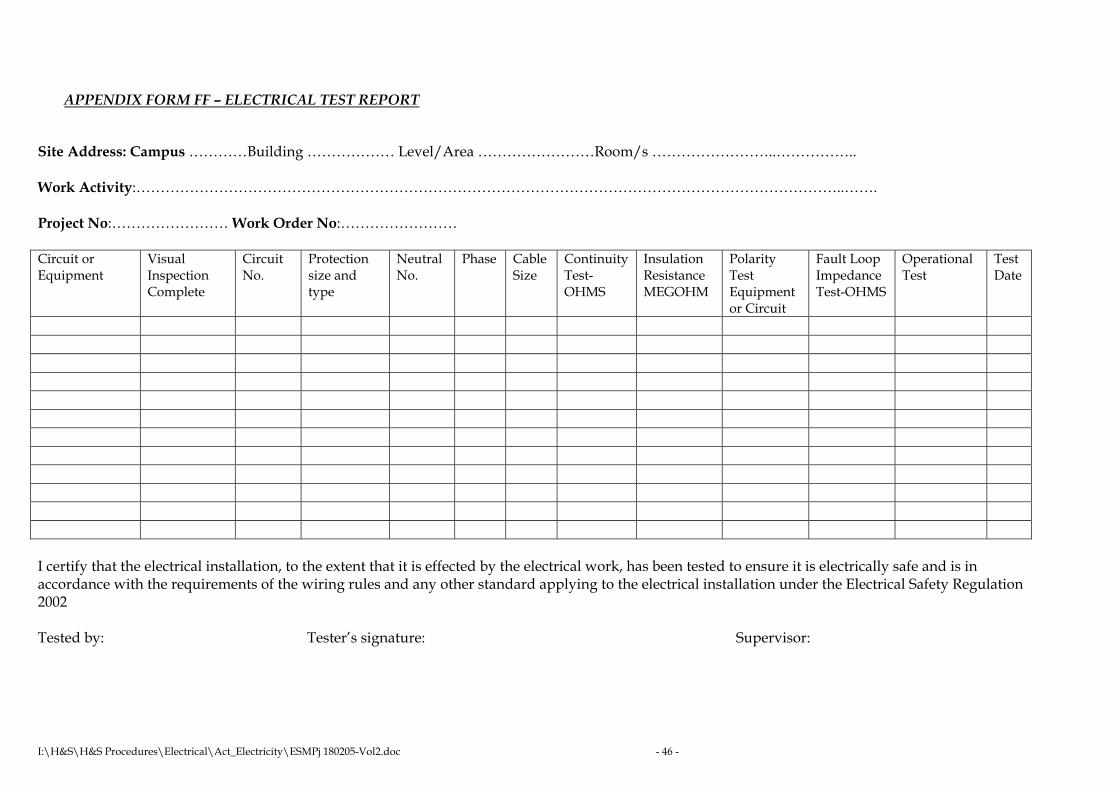
I:\H&S\H&S Procedures\Electrical\Act_Electricity\ESMPj 180205-Vol2.doc - 46 -
APPENDIX FORM FF – ELECTRICAL TEST REPORT
Site Address: Campus …………Building ……………… Level/Area ……………………Room/s ……………………..…………….. Work Activity:………………………………………………………………………………………………………………………………..……. Project No:…………………… Work Order No:…………………… Circuit or Equipment
Visual Inspection Complete
Circuit No.
Protection size and type
Neutral No.
Phase Cable Size
Continuity Test-OHMS
Insulation Resistance MEGOHM
Polarity Test Equipment or Circuit
Fault Loop Impedance Test-OHMS
Operational Test
Test Date
I certify that the electrical installation, to the extent that it is effected by the electrical work, has been tested to ensure it is electrically safe and is in accordance with the requirements of the wiring rules and any other standard applying to the electrical installation under the Electrical Safety Regulation 2002 Tested by: Tester’s signature: Supervisor:

I:\H&S\H&S Procedures\Electrical\Act_Electricity\ESMPj 180205-Vol2.doc - 47 -
APPENDIX FORM GG – SAFETY EQUIPMENT INSPECTION SCHEDULE
Year………… January -June July-December Item Type Item No. Vehicle
No. Required Tested Required Tested
Safety equipment is to be tested in accordance with Procedure 8 – Testing of Electrical Safety Equipment. If an item fails the test details of any repairs and retest are to be recorded. Test records must be retained for 5 years.
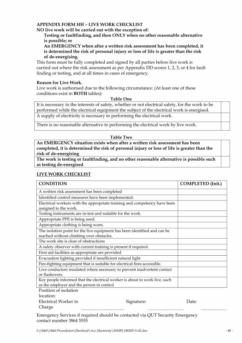
I:\H&S\H&S Procedures\Electrical\Act_Electricity\ESMPj 180205-Vol2.doc - 48 -
APPENDIX FORM HH – LIVE WORK CHECKLIST NO live work will be carried out with the exception of:
Testing or faultfinding, and then ONLY when no other reasonable alternative is possible; or An EMERGENCY when after a written risk assessment has been completed, it is determined the risk of personal injury or loss of life is greater than the risk of de-energising.
This form must be fully completed and signed by all parties before live work is carried out where the risk assessment as per Appendix DD scores 1, 2, 3, or 4 for fault finding or testing, and at all times in cases of emergency. Reason for Live Work. Live work is authorised due to the following circumstance: (At least one of these conditions exist in BOTH tables):
Table One It is necessary in the interests of safety, whether or not electrical safety, for the work to be performed while the electrical equipment the subject of the electrical work is energised.
A supply of electricity is necessary to performing the electrical work.
There is no reasonable alternative to performing the electrical work by live work.
Table Two An EMERGENCY situation exists when after a written risk assessment has been completed, it is determined the risk of personal injury or loss of life is greater than the risk of de-energising
The work is testing or faultfinding, and no other reasonable alternative is possible such as testing de-energised
LIVE WORK CHECKLIST CONDITION COMPLETED (Init.)
A written risk assessment has been completed Identified control measures have been implemented. Electrical workers with the appropriate training and competency have been assigned to the work.
Testing instruments are in-test and suitable for the work. Appropriate PPE is being used. Appropriate clothing is being worn. The isolation point for the live equipment has been identified and can be reached without climbing over obstacles.
The work site is clear of obstructions A safety observer with current training is present if required. First aid facilities as appropriate are provided Evacuation lighting provided if insufficient natural light Fire-fighting equipment that is suitable for electrical fires accessible. Live conductors insulated where necessary to prevent inadvertent contact or flashovers.
Key people informed that the electrical worker is about to work live, such as the employer and the person in control
Position of isolation location:
Electrical Worker in Charge
Signature: Date:
Emergency Services if required should be contacted via QUT Security Emergency contact number 3864 5555
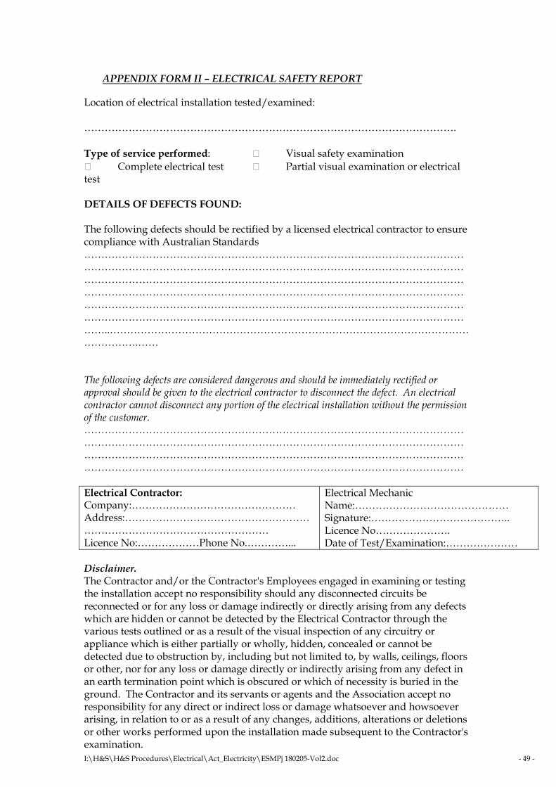
I:\H&S\H&S Procedures\Electrical\Act_Electricity\ESMPj 180205-Vol2.doc - 49 -
APPENDIX FORM II – ELECTRICAL SAFETY REPORT
Location of electrical installation tested/examined: ………………………………………………………………………………………………. Type of service performed: Visual safety examination
Complete electrical test Partial visual examination or electrical test DETAILS OF DEFECTS FOUND: The following defects should be rectified by a licensed electrical contractor to ensure compliance with Australian Standards ……………………………………………………………………………………………………………………………………………………………………………………………………………………………………………………………………………………………………………………………………………………………………………………………………………………………………………………………………………………………………………………………………………………………………………………………………………………..………………………………………………………………………………………………………….…… The following defects are considered dangerous and should be immediately rectified or approval should be given to the electrical contractor to disconnect the defect. An electrical contractor cannot disconnect any portion of the electrical installation without the permission of the customer. ………………………………………………………………………………………………………………………………………………………………………………………………………………………………………………………………………………………………………………………………………………………………………………………………………… Electrical Contractor: Company:………………………………………… Address:……………………………………………………………………………………………… Licence No:………………Phone No.…………...
Electrical Mechanic Name:……………………………………… Signature:………………………………….. Licence No…………………. Date of Test/Examination:…………………
Disclaimer. The Contractor and/or the Contractor's Employees engaged in examining or testing the installation accept no responsibility should any disconnected circuits be reconnected or for any loss or damage indirectly or directly arising from any defects which are hidden or cannot be detected by the Electrical Contractor through the various tests outlined or as a result of the visual inspection of any circuitry or appliance which is either partially or wholly, hidden, concealed or cannot be detected due to obstruction by, including but not limited to, by walls, ceilings, floors or other, nor for any loss or damage directly or indirectly arising from any defect in an earth termination point which is obscured or which of necessity is buried in the ground. The Contractor and its servants or agents and the Association accept no responsibility for any direct or indirect loss or damage whatsoever and howsoever arising, in relation to or as a result of any changes, additions, alterations or deletions or other works performed upon the installation made subsequent to the Contractor's examination.
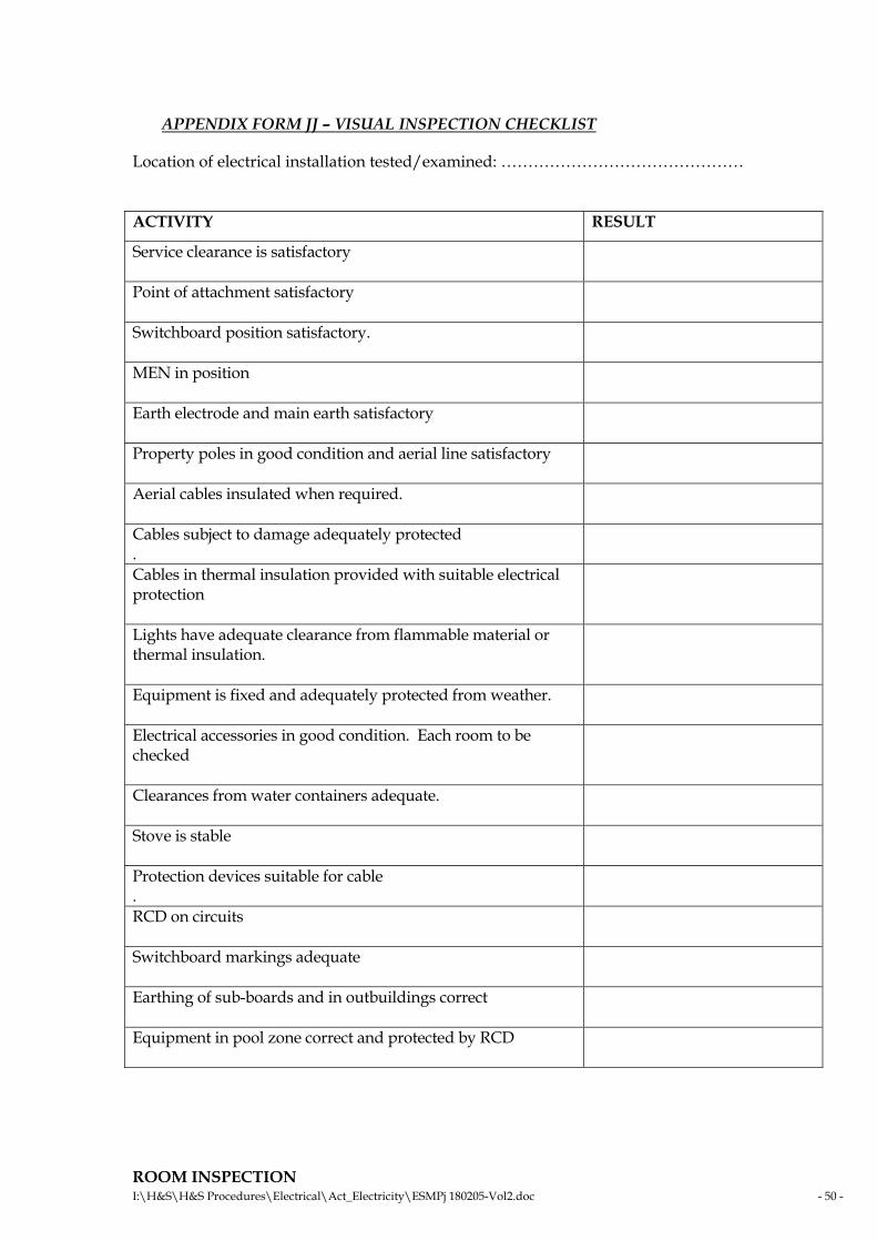
I:\H&S\H&S Procedures\Electrical\Act_Electricity\ESMPj 180205-Vol2.doc - 50 -
APPENDIX FORM JJ – VISUAL INSPECTION CHECKLIST
Location of electrical installation tested/examined: ……………………………………… ACTIVITY RESULT
Service clearance is satisfactory
Point of attachment satisfactory
Switchboard position satisfactory.
MEN in position
Earth electrode and main earth satisfactory
Property poles in good condition and aerial line satisfactory
Aerial cables insulated when required.
Cables subject to damage adequately protected .
Cables in thermal insulation provided with suitable electrical protection
Lights have adequate clearance from flammable material or thermal insulation.
Equipment is fixed and adequately protected from weather.
Electrical accessories in good condition. Each room to be checked
Clearances from water containers adequate.
Stove is stable
Protection devices suitable for cable .
RCD on circuits
Switchboard markings adequate
Earthing of sub-boards and in outbuildings correct
Equipment in pool zone correct and protected by RCD
ROOM INSPECTION

I:\H&S\H&S Procedures\Electrical\Act_Electricity\ESMPj 180205-Vol2.doc - 51 -
ROOM NUMBER/AREA RESULT


