45
SCIENCE FORMATIVE ASSESSMENT 1 Submitted by : Guided By : Prasann Jaiswal Shweta Sood Ma’am Rohan Sharma Dipti Matta Deepank Agrawal Electricity 2015-16
| Date post: | 16-Aug-2015 |
| Category: |
Education |
| Upload: | muskan-jaiswal |
| View: | 1,201 times |
| Download: | 278 times |

SCIENCE FORMATIVE ASSESSMENT 1
Submitted by : Guided By :Prasann Jaiswal Shweta Sood Ma’amRohan SharmaDipti MattaDeepank AgrawalRitik Rathore
Electricity2015-16

ELECRICITY
Contents What is Charge ? Properties of Charge Methods of Charging What is Electricity ? Electric Current Electric Field Electric Potential & Potential Difference Ohm’s Law Resistance Electric Circuit and components Current and Voltage Measurements Combination of Resistances Series vs. Parallel
NOTE-Direction of CONVENTIONAL Current is opposite to direction of flow of electrons.

What isa Charge ?
1.

What is a Charge ?
• Charge is the inherent property of matter that feels force of attraction out repulsion due to excess or deficiency of electrons.
• It is of 2 types :
A. Positive Charge (Due to electron deficiency)
B. Negative Charge (Due to excess of electrons)
• Its S.I. unit is Coulombs denoted by ‘C’.
• It is detected and measured using a device called Electroscope.

Electroscope

PropertiesOf Charge
2.

Properties of Charge
• The total charge of the universe is conserved i.e. constant
• Like Charges attract each other and unlike charges repel each other
• Charges are additive in nature
• Charges are always quantized i.e. Q = n x e
where q = charge,
n = no. of electrons
e = charge on one electron i.e. 1.67 x 10⁻¹⁹ C
• Charge is relativistically constant

Methods ofCharging
3.
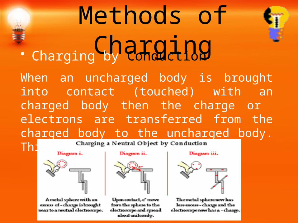
Methods of Charging• Charging by Conduction
When an uncharged body is brought into contact (touched) with an charged body then the charge or electrons are transferred from the charged body to the uncharged body. This charges the uncharged body.

Methods of Charging• Charging by InductionIn the induction process, a charged object is brought near but not touched to a neutral conducting object. The presence of a charged object near a neutral conductor will polarize the charge within the conductor.

What isElectricity ?
4.

What is Electricity ?• Electricity is a form of a energy that can be easily
changed to many other forms.• It can also be defined as flow of electrons in a
circuit.

ElectricCurrent
5.

Electric Current• It is the rate of flow of electric charge (or electrons)
through a conductor i.e.
I = Q/t = ne/t where I stands for current• It is a scalar quantity• Its S.I. unit is coulomb per second or amperes (A)• It is measured by a device called Ammeter• Its direction is taken opposite to the flow of electrons• It flows as a result of potential difference across the
ends of a conductor

Electric Field
6.
Electric Field• It is the 3 dimensional space around a charge in
which the force of attraction or repulsion can be felt.
Electric Field Intensity• It is the force experienced by a unit positive charge
when placed in a magnetic field• It is denoted by ‘E’• Its S.I. unit is newton per coulomb (N/C)• It is a vector quantity

Electric Potentialand
7.
Potential Difference
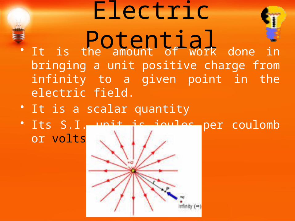
Electric Potential• It is the amount of work done in bringing a unit
positive charge from infinity to a given point in the electric field.
• It is a scalar quantity• Its S.I. unit is joules per coulomb or volts (V)

Potential Difference• It is the amount of work done in bringing a unit positive
charge from one point to another point in an electric field.• It is a scalar quantity• Its S.I. unit is joules per coulomb or volts (V)• It is responsible for the flow of current in a conductor.• Measured by a device called Voltmeter.
. ∞
B. A.
Ohm’sLaw
8.

Ohm’s Law• It was stated by Georg Simon Ohm• It states that at constant physical conditions like temperature
are kept constant then the amount of current flowing through a conductor is directly proportional to the potential difference across its ends i.e.
I α V
V = IR where R is constant called Resistance• According to this law conductors are divide into -
1. Ohmic conductors (follow ohm’s law)
2. Non- ohmic conductors (do not follow ohm’s law)

I-V Graphs for Conductors

Resistance andResistivity
9.

Resistance• It is defined as the hindrance to the flow of current
• It is the ratio of potential difference to current i.e.
R = V/I
• Its S.I. unit is volts per ampere or Ohm (denoted by Ω)
• Reciprocal or resistance is called Conductance (C) . S.I. unit Ohm-1 i.e. Ω-1

Factors affecting Resistance
• R α Length (l) ……(i)• R α 1/Area of cross section of conductor (A) ………(ii)
From (i), (ii) and (iii) we get R α l/A R = ρl/A where constant “ρ” is the specific resistance of the
conductor

Specific Resistance
• Specific resistance is the resistance of a conductor of unit length and unit cross sectional area i.e.
if l = 1 m and A = 1 m2 then R = ρ
• It depends on material of the conductor• Denoted by rho i.e. “ρ”• S.I. unit is Ohm metre (Ωm) • Ρ α Temperature of the conductor• Also known as Resistivity

Resistivity Table

Fixed Resistors Variable resistance or Rheostat
Types of Resistances Fixed Resistances: Their value does not change under
constant physical conditions. They are set at a particular value
Variable Resistances: Their resistance can be easily changed by changing area of cross section and length

Electric Circuitand
10.
Its Components

Electric Circuit
• A closed path in which electric current can flow is called an electric circuit
• There are 2 types of circuits –
1. Open Circuit: No current flows
2. Closed Circuit: Current flows continuously
Open circuit
Closed circuit

MeasuringDevices
11.
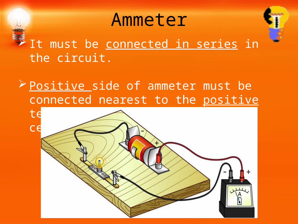
Ammeter It must be connected in series in the circuit.
Positive side of ammeter must be connected nearest to the positive terminal of the battery (electric cell), and vice versa.

Voltmeter Voltmeters must be connected in parallel to the
circuit. The positive side of voltmeter is connected to the
positive terminal of the cell, and vice versa.

Combination of
Resistances
12.
Combination of Resistances
There are 2 ways of joining resistors together
1. Series Combination 2. Parallel Combination

Resistance in Series• When two (or more) resistors are connected end to end
consecutively, they are said to be connected in series.
• When a number of resistors connected in series are joined to the terminal of a battery, then each resistance has a different potential difference across its ends (which depends on the value of resistance). But the total potential difference across all the ends of all the resistors in series is equal.
• When a number of resistors are connected in series, then the same current flows through each resistance

Resistance in Series• The figure shows three resistances R1,R2,R3 connected in series. Now suppose
potential difference across resistance R1 is V1 , R2 is V2 and R3 is V3. Let potential difference across battery be V, then :
V = V1+V2+V3.
Applying Ohm’s law to the whole circuit : V = IR. ………..(1)
Applying Ohm’s law to the three resistors separately, we get:
V1 = I x R1. ………………….. (2)
V2 = I x R2. ………………….. (3)
V3 = I x R3. ………………….. (4)
Substituting (2), (3), (4) in (1)
IR = IR1 + IR2+ IR3
OR, IR= I (R1+R2+R3)
Or, R = R1+R2+R3 .
Therefore we conclude that the sum total resistance in a series resistance connection is equal to the sum of all the resistances.

Resistance in Parallel• When two (or more) resistors are connected between the same
points, they are said to be connected in parallel.
• When a number of resistance are connected in parallel, then the potential difference across each resistance is same which is equal to the voltage of battery applied.
• Different amounts of current flows through each resistance (which depend on the value of resistance). But the current flowing through each parallel resistance, taken together, is equal to the current flowing in the circuit as a whole. Thus, when a number of resistance are connected in parallel, then the sum of current flowing through all the resistances is equal to the total current flowing in the circuit.
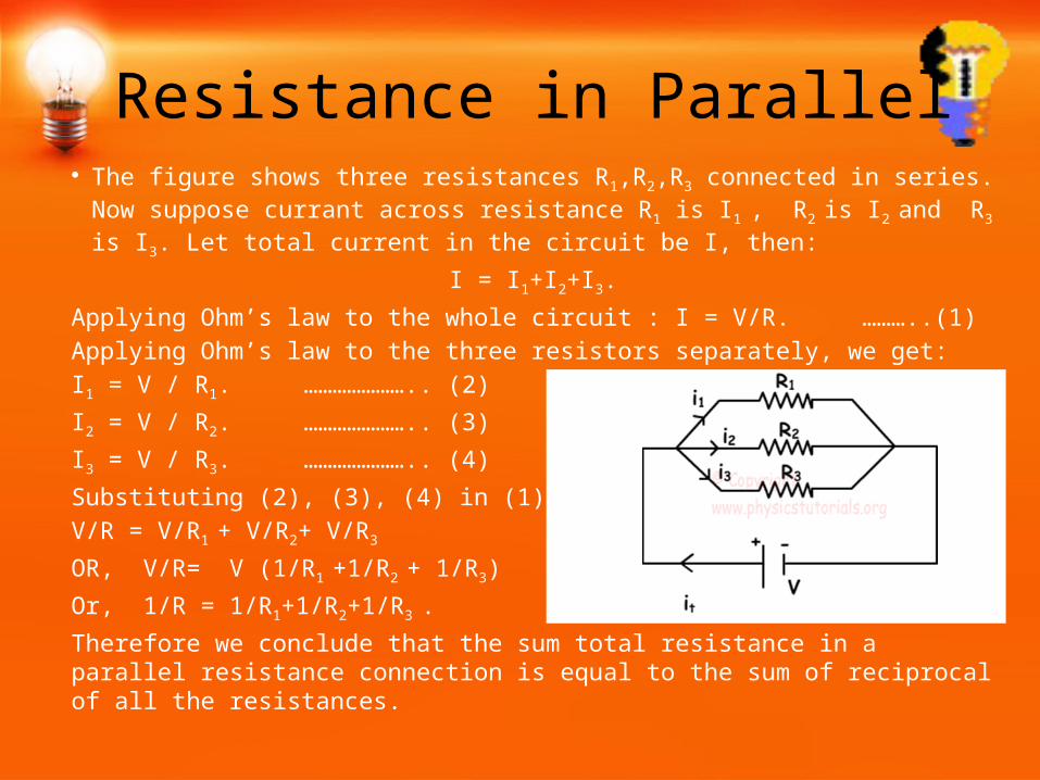
Resistance in Parallel• The figure shows three resistances R1,R2,R3 connected in series. Now suppose
currant across resistance R1 is I1 , R2 is I2 and R3 is I3. Let total current in the circuit be I, then:
I = I1+I2+I3.
Applying Ohm’s law to the whole circuit : I = V/R. ………..(1)
Applying Ohm’s law to the three resistors separately, we get:
I1 = V / R1. ………………….. (2)
I2 = V / R2. ………………….. (3)
I3 = V / R3. ………………….. (4)
Substituting (2), (3), (4) in (1)
V/R = V/R1 + V/R2+ V/R3
OR, V/R= V (1/R1 +1/R2 + 1/R3)
Or, 1/R = 1/R1+1/R2+1/R3 .
Therefore we conclude that the sum total resistance in a parallel resistance connection is equal to the sum of reciprocal of all the resistances.

SeriesVs.
13.
Parallel

Series vs. ParallelS.No. Criteria Series Parallel
1.Equivalent Resistance
More than the highest resistor
Less than or equal to the lowest resistor
2.Amount of Current Current is less as
resistance is moreCurrent is more as resistance is more
3. Switching on/offIf one is appliance is switched off others also do not work
If one is appliance is switched off others work independently
4. Appliance failureIf one appliance stops working, none of the appliances will work
If one appliance stops working, others will work independently
5.Potential Difference
Each appliance receives maximum potential difference
Potential Difference is divided so, each appliance receives less P.D.

THANK YOU


