Dipartimento di Ingegneria dell’Innovazione, Università del Salento, via Monteroni, I-73100 Lecce, ItalyElettra – Sinctrotrone Trieste S.C.p.A. S.S. 14, km 163.5 in Area Science Park, 34149 Trieste-Basovizza, Italy
r t i c l e i n f o
rticle history:eceived 17 January 2013eceived in revised form 10 July 2013ccepted 11 July 2013vailable online 16 July 2013
eywords:upercapacitorold-manganese alloys
onic liquidlectrodeposition
a b s t r a c t
In a previous paper (C. Mele, M. Catalano, A. Taurino, B. Bozzini. Electrochim. Acta 1 (2013) 918), wedemonstrated the possibility of growing high-capacitance hybrid materials consisting of nanoporousgold (NPG)-supported MnO2 nanowires (NW) for supercapacitors, by electrochemical etching of elec-trodeposited single-phase Au–Mn alloys. The present paper concentrates on the electrodeposition ofAu–Mn alloys from urea/choline-chloride ionic liquid solutions: the precursors of the high-capacitancehybrid material. The electrodeposition process, giving rise to alloys with 4–26% Mn content, wasfollowed by space-resolved soft X-ray fluorescence (XRF) and absorption (XAS) microspectroscopy,complemented with electrochemical (cyclic voltammetry), structural (X-ray diffraction) and morpho-logical (scanning electron microscopy) characterisations. The purposely developed electrochemical cells,exhibiting a specifically designed current density distribution, have allowed the quasi-in situ mapping of
-ray microspectroscopy the local morphology-composition changes at the electrodes. Supersaturated Au–Mn solid solutions wereobtained in the whole investigated compositional range under mass transport control of Mn. Variationsin the Mn oxidation state were evidenced comparing low- and high-Mn content regions. It was foundthat, notwithstanding the heterogeneity of the current density, the morphologically compact high-Mnregions of the particular alloys with 20–26% Mn show a notable compositional homogeneity, renderingthis material ideally suited for the fabrication of the target hybrid.
. Introduction
In supercapacitor technology, manganese oxide is a promisinglternative to highly performing, but notably expensive, ruthe-ium oxide [1–3]. Electrodeposition of manganese from aqueousolutions exhibits serious process-control and product qualityroblems: in particular, the roughness of the coatings is generallyxcessive for practical applications, essentially owing to the highate of concurrent hydrogen evolution. For this reason, the use ofoom temperature ionic liquids (RTIL) as solvents is appealing [4,5].
e have already demonstrated that manganese oxide nanowires6] and nanoporous-gold (NPG)-supported MnO2 nanowires [7]ith excellent capacitive properties can be obtained by elec-
rodeposition from eutectic urea/choline chloride ionic liquid. Inarticular, we have proposed a novel fabrication approach, con-isting in Mn electrodeposition from an ionic-liquid bath, followed
by controlled electrochemical oxidation in an aqueous solution[6]. These studies were extended by fabricating nanoporous gold(NPG)-supported manganese oxide nanowires using a similar two-step method: (i) electrodeposition from choline chloride/ureaeutectic ionic-liquid of a suitable Au–Mn alloy, (ii) electrochemi-cally controlled selective corrosion of Mn in an aqueous solution,resulting in the simultaneous formation of the NPG support and ofthe functional Mn-oxide decorating the nanopores [7].
The electrodeposition processes of Mn and Au–Mn, as wellas their electro-oxidation processes, have been studied by elec-trochemical and in situ visible electroreflectance, allowing todiscriminate dynamically the type of Mn oxide on the basis ofrelative reflectivity changes [6,7]. Moreover, the Mn valence distri-bution on the electrodes and within the cell were measured in situby synchrotron-based soft X-ray scanning microspectroscopy [6].The capacitance of the final material was also tested by cyclic
voltammetry and electrochemical impedance spectrometry. MnO2grown in this way was found to exhibit the highest specific capac-ity among MnO2-based supercapacitor materials: this property isfurther enhanced if the material is supported onto NPG.
890 B. Bozzini et al. / Electrochimica Acta 114 (2013) 889– 896
F ll afted
fiatrlocspw
2
cpcw3rabtosicw(efprssbndoiBsc[
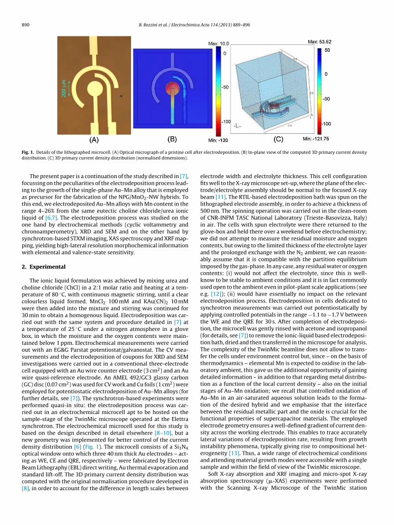
ig. 1. Details of the lithographed microcell. (A) Optical micrograph of a pristine ceistribution. (C) 3D primary current density distribution (normalised dimensions).
The present paper is a continuation of the study described in [7],ocussing on the peculiarities of the electrodeposition process lead-ng to the growth of the single-phase Au–Mn alloy that is employeds precursor for the fabrication of the NPG/MnO2-NW hybrids. Tohis end, we electrodeposited Au–Mn alloys with Mn content in theange 4–26% from the same eutectic choline chloride/urea ioniciquid of [6,7]. The electrodeposition process was studied on thene hand by electrochemical methods (cyclic voltammetry andhronoamperometry), XRD and SEM and on the other hand byynchrotron-based STXM imaging, XAS spectroscopy and XRF map-ing, yielding high-lateral resolution morphochemical informationith elemental and valence-state sensitivity.
. Experimental
The ionic liquid formulation was achieved by mixing urea andholine chloride (ChCl) in a 2:1 molar ratio and heating at a tem-erature of 80 ◦C, with continuous magnetic stirring, until a clearolourless liquid formed. MnCl2 100 mM and KAu(CN)2 10 mMere then added into the mixture and stirring was continued for
0 min to obtain a homogenous liquid. Electrodeposition was car-ied out with the same system and procedure detailed in [7] at
temperature of 25 ◦C under a nitrogen atmosphere in a gloveox, in which the moisture and the oxygen contents were main-ained below 1 ppm. Electrochemical measurements were carriedut with an EG&G Parstat potentiostat/galvanostat. The CV mea-urements and the electrodeposition of coupons for XRD and SEMnvestigations were carried out in a conventional three-electrodeell equipped with an Au wire counter electrode (3 cm2) and an Auire quasi-reference electrode. An AMEL 492/GC3 glassy carbon
GC) disc (0.07 cm2) was used for CV work and Cu foils (1 cm2) weremployed for potentiostatic electrodeposition of Au–Mn alloys (forurther details, see [7]). The synchrotron-based experiments wereerformed quasi-in situ: the electrodeposition process was car-ied out in an electrochemical microcell apt to be hosted on theample-stage of the TwinMic microscope operated at the Elettraynchrotron. The electrochemical microcell used for this study isased on the design described in detail elsewhere [8–10], but aew geometry was implemented for better control of the currentensity distribution [6] (Fig. 1). The microcell consists of a Si3N4ptical window onto which three 40 nm thick Au electrodes – act-ng as WE, CE and QRE, respectively – were fabricated by Electron
eam Lithography (EBL) direct writing, Au thermal evaporation andtandard lift-off. The 3D primary current density distribution wasomputed with the original normalisation procedure developed in8], in order to account for the difference in length scales between
r electrodeposition. (B) In-plane view of the computed 3D primary current density
electrode width and electrolyte thickness. This cell configurationfits well to the X-ray microscope set-up, where the plane of the elec-trode/electrolyte assembly should be normal to the focused X-raybeam [11]. The RTIL-based electrodeposition bath was spun on thelithographed electrode assembly, in order to achieve a thickness of500 nm. The spinning operation was carried out in the clean-roomof CNR-INFM TASC National Laboratory (Trieste-Basovizza, Italy)in air. The cells with spun electrolyte were there returned to theglove-box and held there over a weekend before electrochemistry;we did not attempt to measure the residual moisture and oxygencontents, but owing to the limited thickness of the electrolyte layerand the prolonged exchange with the N2 ambient, we can reason-ably assume that it is compatible with the partition equilibriumimposed by the gas-phase. In any case, any residual water or oxygencontents: (i) would not affect the electrolyte, since this is well-know to be stable to ambient conditions and it is in fact commonlyused open to the ambient even in pilot-plant scale applications (seee.g. [12]); (ii) would have essentially no impact on the relevantelectrodeposition process. Electrodeposition in cells dedicated tosynchrotron measurements was carried out potentiostatically byapplying controlled potentials in the range −1.1 to −1.7 V betweenthe WE and the QRE for 30 s. After completion of electrodeposi-tion, the microcell was gently rinsed with acetone and isopropanol(for details, see [7]) to remove the ionic-liquid based electrodeposi-tion bath, dried and then transferred in the microscope for analysis.The complexity of the TwinMic beamline does not allow to trans-fer the cells under environment control but, since – on the basis ofthermodynamics – elemental Mn is expected to oxidise in the lab-oratory ambient, this gave us the additional opportunity of gainingdetailed information – in addition to that regarding metal distribu-tion as a function of the local current density – also on the initialstages of Au–Mn oxidation; we recall that controlled oxidation ofAu–Mn in an air-saturated aqueous solution leads to the forma-tion of the desired hybrid and we emphasise that the interfacebetween the residual metallic part and the oxide is crucial for thefunctional properties of supercapacitor materials. The employedelectrode geometry ensures a well-defined gradient of current den-sity across the working electrode. This enables to trace accuratelylateral variations of electrodeposition rate, resulting from growthinstability phenomena, typically giving rise to compositional het-erogeneity [13]. Thus, a wide range of electrochemical conditionsand attending material growth modes were accessible with a single
sample and within the field of view of the TwinMic microscope.
Soft X-ray absorption and XRF imaging and micro-spot X-rayabsorption spectroscopy (�-XAS) experiments were performedwith the Scanning X-ray Microscope of the TwinMic station
imica Acta 114 (2013) 889– 896 891
oTfswXapXutotMclmXMsodtftss
ctaewtedo
3
3
etcm
3
FupPt1−wptQed�−
20–33.3 at.% Mn [17,18]. Our diffractograms reveal an out-of-equilibrium structure consisting of a supersaturated solid solutionwith the terminal Au fcc structure: this is a common phenomenonin alloy electrodeposition [19]. Concerning the deposit at −0.7 V,
B. Bozzini et al. / Electroch
perated at the Elettra synchrotron facility (Trieste, Italy) [14,15].he microprobe of sizes 0.01–1 �m2 was provided by zone plateocusing optics and the maps were obtained by scanning theample and monitoring simultaneously the transmitted X-raysith a CCD detector placed behind the sample and the emittedRF signals with fluorescence detectors placed in the front partt grazing angles. It should be noted that whereas the XRF mapsrovide quantitative elemental information, the contrast in the-ray absorption map of multicomponent systems cannot providenambiguous elemental information, since it is determined byotal absorption of the X-rays by the sample constituents. Indeedur absorption maps were taken with photon energy close abovehe Mn L edge (638.7 eV), which should reflect better the local
n density, but Au is also strongly absorbing and obscures theontribution from local Mn content. In addition, the evolution andateral distribution of the Mn chemical state was monitored by
easuring the Mn L3 �-XAS spectra in selected microspots. TheAS spectra were calibrated with the following standard materials:nSO4, MnCO3, MnCl2, MnO2 and KMnO4 in fine powder form,
upported onto Au TEM grids and an Au-capped Mn foil evaporatednto a 50 nm Si3N4 membrane. The present experimental set-upoes not allow to scan the photon energy keeping simultaneouslyhe microprobe size constant by adjusting the photon-dependentocal distance: as a result, regions up to 8–10 �m2 contribute tohe �-XAS data at the end of the photon energy scan. However,ince the focus was aligned to the Mn-L3 edge onset, the �-XASpectra provide accurate local chemical-state information on Mn.
Low-resolution EDX mapping (20 �m lateral resolution) wasarried out with a Bruker M4 Tornado micro XRF spectrome-er. The surface morphology of the samples was examined with
Cambridge Stereoscan scanning electron microscope (SEM)quipped with an EDX microprobe. X-ray diffraction analysesere also performed to explore the crystallographic structure of
he Au–Mn deposits: an Ultima + Rigaku diffractometer was used,quipped with a Bragg–Brentano goniometer. The sample was irra-iated with a monochromatic Cu K� radiation with a wavelengthf 0.154 nm.
. Results and discussion
.1. Electrodeposition of Au–Mn alloys
The electrodeposition of Au–Mn alloys was studied by standardlectrochemical methods, EDX, SEM and XRD in order to identifyhe appropriate potential window for the process as well as theorrelation among electrodeposition conditions, alloy composition,orphology and crystallographic structure.
.1.1. Electrochemical measurementsA CV of a GC electrode in 2:1 urea/ChCl is reported in
ig. 2A, displaying the electrochemical window of the ionic liq-id, extending from ca. 1 V to ca. −2 V. Cognate measurement,erformed on an Au electrode are discussed in Fig. 1a of [7].lot 2-B reports a CV recorded with the GC electrode in con-act with the electrolyte containing MnCl2 100 mM and KAu(CN)20 mM, showing that Au and Mn reduction take place at ca.1.0 and −1.4 V, coherently with literature data [6,7,16]: wellithin the electrochemical window. Electrodeposition of sam-les for EDX and SEM characterisation was performed for 1 h athe following potentials: −0.7, −1.1, −1.5, 1.7 and −1.9 V vs. AuRE. The circulated charge per unit area �q and the cathodic
fficiency �c, estimated from gravimetric and compositionalata, are listed below: −0.7 V �q = 82 mC cm−2, �c = 100%; −1.1 Vq = 0.26 C cm−2, �c = 98.3%; −1.5 V �q = 0.69 C cm−2, �c = 94.2%;1.7 V �q = 1.3 C cm−2, �c = 91%; −1.9 V �q = 6.5 C cm−2, �c = 35%.
Fig. 2. Cyclic voltammograms of: (A) GC electrode in 2:1 urea/ChCl; (B) same elec-trode in the same electrolyte, with added MnCl2 100 mM, KAu(CN)2 10 mM. Potentialscan rate of 0.1 V/s.
3.1.2. Alloy compositionThe composition of the electrodeposited alloy was evaluated by
EDX, exhibiting a potential vs. composition relationship (Fig. 3) typ-ical of regular codeposition systems, where the less noble species(Mn) is deposited when mass-transport control conditions for themore noble one (Au) are achieved.
3.1.3. Crystallographic structureThe crystallographic structure of Au–Mn electrodeposits was
determined by XRD: the diffractograms corresponding to alloysof different composition, grown potentiostatically are reportedin Fig. 4, with the corresponding peak assignment. The equilib-rium Au–Mn system at room temperature comprises nine phasesand it is relatively complex, especially in the composition range
Fig. 3. Alloy composition as a function of electrodeposition potential. Bath: 2:1urea/ChCl, MnCl2 100 mM, KAu(CN)2 10 mM. Electrodeposition time: 1 h.
892 B. Bozzini et al. / Electrochimica
Fig. 4. X-ray diffractograms of Au–Mn alloys electrodeposited at the indicatedps
inmsppdbtohkba
FK
otentials vs. Au QRE. Bath: 2:1 urea/ChCl, MnCl2 100 mM, KAu(CN)2 10 mM, Cuubstrate. Electrodeposition time: 1 h.
t is worth noting that, even though Au can be detected by EDX,o diffraction peaks corresponding to the Au fcc phase could beeasured. As far as the structural effects of composition in solid
olutions are concerned, the first approximation is Végard’s lawredicting a linear variation of the lattice parameters with com-osition. Nevertheless, in many cases like in the one at hand, thisependence is found not to be followed. Several explanations haveeen put forward in the literature to explain such deviations, essen-ially consisting in non-ideal solution behaviour. In the specific casef our electrodeposited Au–Mn supersaturated solid solution, weave found that the fcc lattice parameter exhibits a maximum. This
ind of dependence has not been pointed out in the Au–Mn system,ut it in nevertheless known in other alloys, specifically, in Au-richlloys with a small lattice mismatch [20].
ig. 5. In-plane SEM micrographs of Au–Mn alloys electrodeposited at: (A) −0.7, (B) −1Au(CN)2 10 mM, Cu substrate. Electrodeposition time: 1 h.
Acta 114 (2013) 889– 896
3.1.4. Electrodeposit morphologyThe SEM micrographs in Fig. 5 show the in-plane morphology
of the Au–Mn deposits obtained potentiostatically at the above-listed potentials. Three kinds of morphological regimes were found.(i) The pure Au deposit obtained at −0.7 V (Panel A) follows thesubstrate in a conformal way. (ii) In the interval −1.1 to −1.7 V glob-ular structures form, that are typical of electrodeposited Mn andits alloys [21–23], with different degrees of surface coverage andglobule dimensions, following the overvoltage. At −1.1 V (Panel B)the very low overvoltage gives rise to a low surface coverage withtiny grains on a background of nuclei, at −1.5 V (Panel C) largerglobuli tend to develop owing to the higher activation overvolt-age accompanied by minor mass-transport contributions, while at−1.7 V (Panel D) finer globuli form, as a result of enhanced nuclea-tion rate: for mechanicistic details, see e.g. [13]. (iii) Eventually, at−1.9 V (Panel E) plate-like crystallites are found, typical of unstable,high-rate Au electrodeposition (see e.g. [24]).
3.2. X-ray absorption microscopy, XRF imaging and X-rayabsorption microspectroscopy (�-XAS)
In order to achieve an insightful understanding of the electrode-position process, representative regions of the microcell includingthe cathode, the electrolyte, the reference electrode and the anode(for details, see Section 2) were characterised by means of X-rayabsorption and XRF imaging combined with �-XAS from selectedregions from the images. The electrochemically active areas of thecathode were imaged under the three most significant conditionsdemonstrated in Section 3.1.2 to correspond to the formation ofrepresentative alloy compositions: (−1.1 V (4% Mn), −1.5 V (20%Mn) and −1.7 V (26% Mn)). It is worth recalling here that −1.7 V isthe optimal plating condition for the fabrication of supercapacitormaterial [7]. Fig. 6 shows optical and SEM micrographs togetherwith low-resolution EDX maps of the whole electrodic system,
showing the Mn distribution obtained in the above-mentionedplating conditions. The lateral resolution of the EDX microscopeused for imaging on the whole-cell scale is suitable to follow theoverall electrodeposit distribution. It can be noticed that the Mn
.1, (C) −1.5, (D) −1.7, (E) −1.9 V vs. Au QRE. Bath: 2:1 urea/ChCl, MnCl2 100 mM,
B. Bozzini et al. / Electrochimica Acta 114 (2013) 889– 896 893
Fig. 6. Optical and SEM micrographs with low-resolution EDX maps of microcells onto whose cathodes (WE) Au–Mn alloys have been electrodeposited at the followingpotentials: (A) −1.1 V (3.7% Mn), (B) −1.5 V (20.2% Mn), (C) −1.7 V (25.8% Mn) and (D) −1.9 V (26% Mn). The whole three-electrode microcells are displayed: WE workingelectrode (cathode), RE reference electrode, CE counter electrode (anode).
Fig. 7. (A) Optical micrograph of the cell with Au–Mn electrodeposited at −1.1 V where the X-ray absorption image indicates the mapped 80 �m × 80 �m zone. (B)75 �m × 75 �m Mn XRF map measured with photon energy 821 eV: representative high- and low-current density regions are indicated. (C) O XRF map. (D) Mn L-edge�-XAS taken in location indicated in (E) 80 �m × 80 �m X-ray absorption map of the electrode measured with photon energy 650 eV.
894 B. Bozzini et al. / Electrochimica Acta 114 (2013) 889– 896
Fig. 8. (A) X-ray absorption image of microcell with Au–Mn electrodeposited at −1.5 V where each tile covers 80 �m × 80 �m zone (photon energy 650 eV). The red squarei ensityr asure
lblgdea(isd
O3id
mctgdepaof
ndicates the regions analysed with XRF and �-XAS: (a) high- and (b) low-current degions (a) (80 �m × 80 �m) (b) (40 �m × 11 �m, 821 eV). (C) Mn L-edge �-XAS me
ocalisation – regardless of the fine spatial details that are addressedy the high-resolution XRF mapping presented in Figs. 7–9 – fol-
ows, especially at the lower cathodic potentials where unstablerowth has not developed, the computed cathodic current densityistribution depicted in Fig. 1B. Moreover, as expected from thelectrochemistry of Mn(II) baths (for more details, refer to [6]), Mnlso deposits on the anode as well as on the reference electrodethis effect is particularly noticeable at the higher cathodic polar-sations) owing to bipolar effects [25]. In view of applications toupercapacitor fabrication, we concentrated only on the cathodiceposits.
Figs. 7–9 show representative X-ray absorption maps, Mn and XRF maps and Mn L3 �-XAS spectra for Au–Mn alloys grown for0 s at −1.1, −1.5 and −1.7 V. The �-XAS spectra were measured
n locations that are characteristic of the prevailing current densityistributions.
At -1.1 V (Fig. 7, Panels A-C), higher amounts of electrodepositedaterial and higher Mn concentrations are found at the edge of the
athode, where the current density is higher (see Fig. 1B). Represen-ative areas of the cathode were analysed where electrodepositionradients develop, in accord with the computed current densityistribution. The contrast variations of the Mn and O maps aressentially the same; this correlation between the two elements
roves that Mn in the Au–Mn alloy is oxidised when exposed toir during the transfer to the analysis chamber; details on selectivexidation of Mn in Au–Mn solid solutions can be found in [7]. Asar as the effect of the current density distribution is concerned, the
. (B) Mn (B1, B3) and O (B2, B4) XRF maps measured with photon energy 821 eV ind in the locations indicated in the X-ray absorption maps shown in the centre.
computed gradient is clearly confirmed: no qualitative differencescan be noticed between the side of the cathode facing the RE andthat facing the CE.
The Mn L-edge �-XAS spectra in Fig. 7 Panels D and E confirm theMn distribution in the XRF maps and provide additional informa-tion about the local Mn oxidation state in representative regionsof the electrodeposit grown at −1.1 V. In point 1 no Mn is found,coherently with the low local current density that gives rise tothe electrodeposition of pure Au (see Section 3.1.2). Since Au isa stronger absorber compared to Mn, this accounts for the almostuniform contrast in the X-ray absorption map despite the fact thatit is measured with an X-ray energy far above the Au M absorp-tion edge. In points 2 and 3, closer to the cathode edge, where thecurrent density was higher, the Mn �-XAS spectra have a slightlydifferent intensity and also different peak positions, indicating localvariations in both Mn content and oxidation state. The degree ofoxidation matches the Mn fraction in the Au–Mn alloy that, in turn,is coherent with the location of the analysis point with respect tothe current density gradient. The Mn state corresponding to higher-Mn alloys, deposited in higher-current density locations (point 2), ispresent as a mixed Mn2+/Mn3+ oxide, while lower-Mn alloys (point3) also contain Mn0. The observed oxidation-state distribution canbe interpreted in terms of the degree of charge-transfer between
Au substrate and Mn crystals: better electronic contact correspondsto more reduced Mn state [26]. We recall that an excellent contactbetween the insulating, but faradaically active Mn oxide and theAu matrix is crucial for the electronic performance of this hybrid
B. Bozzini et al. / Electrochimica Acta 114 (2013) 889– 896 895
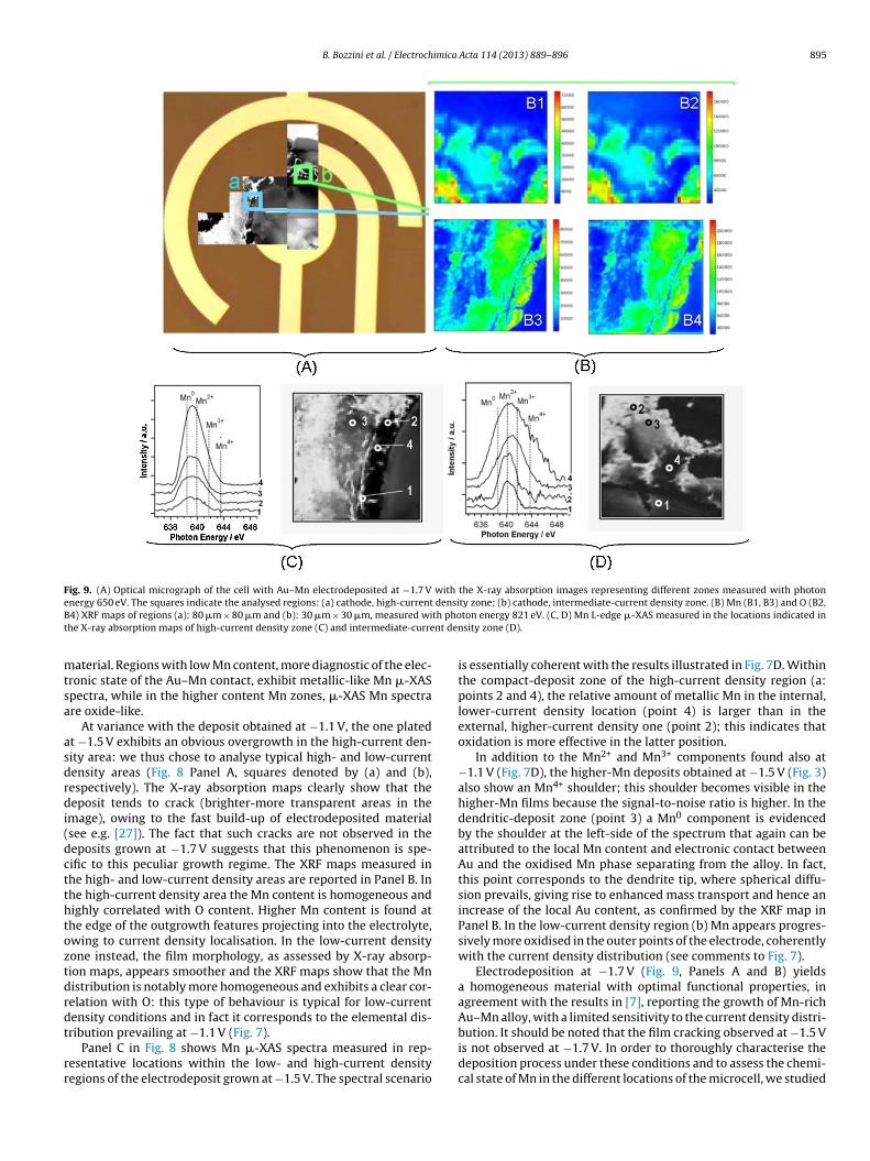
Fig. 9. (A) Optical micrograph of the cell with Au–Mn electrodeposited at −1.7 V with the X-ray absorption images representing different zones measured with photone densiB th phot nt den
mtsa
asdrdi(dctthtoztdrdt
rr
nergy 650 eV. The squares indicate the analysed regions: (a) cathode, high-current4) XRF maps of regions (a): 80 �m × 80 �m and (b): 30 �m × 30 �m, measured wihe X-ray absorption maps of high-current density zone (C) and intermediate-curre
aterial. Regions with low Mn content, more diagnostic of the elec-ronic state of the Au–Mn contact, exhibit metallic-like Mn �-XASpectra, while in the higher content Mn zones, �-XAS Mn spectrare oxide-like.
At variance with the deposit obtained at −1.1 V, the one platedt −1.5 V exhibits an obvious overgrowth in the high-current den-ity area: we thus chose to analyse typical high- and low-currentensity areas (Fig. 8 Panel A, squares denoted by (a) and (b),espectively). The X-ray absorption maps clearly show that theeposit tends to crack (brighter-more transparent areas in the
mage), owing to the fast build-up of electrodeposited materialsee e.g. [27]). The fact that such cracks are not observed in theeposits grown at −1.7 V suggests that this phenomenon is spe-ific to this peculiar growth regime. The XRF maps measured inhe high- and low-current density areas are reported in Panel B. Inhe high-current density area the Mn content is homogeneous andighly correlated with O content. Higher Mn content is found athe edge of the outgrowth features projecting into the electrolyte,wing to current density localisation. In the low-current densityone instead, the film morphology, as assessed by X-ray absorp-ion maps, appears smoother and the XRF maps show that the Mnistribution is notably more homogeneous and exhibits a clear cor-elation with O: this type of behaviour is typical for low-currentensity conditions and in fact it corresponds to the elemental dis-
ribution prevailing at −1.1 V (Fig. 7).
Panel C in Fig. 8 shows Mn �-XAS spectra measured in rep-esentative locations within the low- and high-current densityegions of the electrodeposit grown at −1.5 V. The spectral scenario
ty zone; (b) cathode, intermediate-current density zone. (B) Mn (B1, B3) and O (B2,ton energy 821 eV. (C, D) Mn L-edge �-XAS measured in the locations indicated insity zone (D).
is essentially coherent with the results illustrated in Fig. 7D. Withinthe compact-deposit zone of the high-current density region (a:points 2 and 4), the relative amount of metallic Mn in the internal,lower-current density location (point 4) is larger than in theexternal, higher-current density one (point 2); this indicates thatoxidation is more effective in the latter position.
In addition to the Mn2+ and Mn3+ components found also at−1.1 V (Fig. 7D), the higher-Mn deposits obtained at −1.5 V (Fig. 3)also show an Mn4+ shoulder; this shoulder becomes visible in thehigher-Mn films because the signal-to-noise ratio is higher. In thedendritic-deposit zone (point 3) a Mn0 component is evidencedby the shoulder at the left-side of the spectrum that again can beattributed to the local Mn content and electronic contact betweenAu and the oxidised Mn phase separating from the alloy. In fact,this point corresponds to the dendrite tip, where spherical diffu-sion prevails, giving rise to enhanced mass transport and hence anincrease of the local Au content, as confirmed by the XRF map inPanel B. In the low-current density region (b) Mn appears progres-sively more oxidised in the outer points of the electrode, coherentlywith the current density distribution (see comments to Fig. 7).
Electrodeposition at −1.7 V (Fig. 9, Panels A and B) yieldsa homogeneous material with optimal functional properties, inagreement with the results in [7], reporting the growth of Mn-richAu–Mn alloy, with a limited sensitivity to the current density distri-
bution. It should be noted that the film cracking observed at −1.5 Vis not observed at −1.7 V. In order to thoroughly characterise thedeposition process under these conditions and to assess the chemi-cal state of Mn in the different locations of the microcell, we studied
8 imica
t(scewrXttci
htg(idtaBcmptcac
4
ptpmg–wcecTiuWcrlcpMwetw
R
[
[
[[
[
[
[
[
[
[
[
[
[
[
[
[
96 B. Bozzini et al. / Electroch
wo areas of the cathode with different relative current densities:a) higher-current density, facing the anode; (b) lower-current den-ity, facing the reference electrode. It is worth noting that area (b)orresponds to a position that in the pristine cell belonged to thelectroyte and consequently was not initially in electronic contactith the working electrode; lateral growth of the electrodeposit
esulted in alloy electrodeposition also in this region. The Mn and ORF maps measured in the high-current density zone further prove
he limited sensitivity of the properties of films deposited at −1.7 Vo variations in local electrochemical conditions. The same type ofompositional distribution is also found in the dendrites projectingnto the electrolyte region.
Panels C and D of Fig. 9 show Mn �-XAS spectra measured inigh- (a) and intermediate (b) current density locations of the elec-rodeposit grown at −1.7 V, spanning the electrodic current densityradient. All spectra measured in the high-current density zonePanel C) exhibit essentially the same chemical state, correspond-ng to projecting-dendrite conditions discussed in the case of theeposit grown at −1.5 V. The differences in peak height are due tohickness differences of the electrodeposits rather than differentlloy contents, as indicated by the corresponding XRF map (Panel). In Panel D points 1 and 2 – exhibiting lower Mn contents, thatan be explained on the basis of the current density distribution andass-transport conditions – a Mn0 component is observed, while in
oints 3 and 4 – where planar diffusion prevails and consequentlyhe limiting current density for Au deposition is lower – higher Mnontents are obtained and the oxidised Mn species prevail; again,s with electrodeposits obtained at −1.5 V, also Mn4+ is found inorrespondence of high Mn contents of the alloy.
. Conclusions
This work reports a detailed investigation of Au–Mn electrode-osition from an urea/choline-chloride ionic liquid solution, ashe first step of a novel, integrally electrochemical method –roposed in [7] – for the fabrication of a hybrid supercapacitoraterial based on MnO2 nanowires (NW) supported on nanoporous
old (NPG). Cyclic voltammetry shows that the investigated alloy in the composition range from 4 to 26% – can be depositedithin the electrochemical window of the electrolyte by regular
odeposition. XRD shows that in the compositional range of inter-st, supersaturated solid solutions form: the phase structure ofhoice for the dealloying processes yielding nanoporous metals.he use of synchrotron-based scanning X-ray microscopy combin-ng X-ray absorption and XRF imaging with �-XAS has providednique, space-resolved insight into the electrodeposition process.e followed the dependence of the elemental and valence-state
omposition on the local current density under conditions givingise to both compact and dendritic alloys, coherently with the regu-ar codeposition process under either planar or spherical diffusionontrol; the microspectroscopy results closely match theoreticalredictions based on finite-element computations. In particular,n �-XAS – showing the prevalence of elemental Mn in contactith the Au matrix – indicates that the adopted fabrication route
nsures the intimate electronic contact that is highly desirable forhe optimal combination of low-conductivity active MnO2 NWsith high-conductivity NPG.
eferences
[1] M.-J. Deng, P.-Y. Chen, I.-W. Sun, Electrochemical study and electrode-position of manganese in the hydrophobic butylmethylpyrrolidiniumbis((trifluoromethyl)sulfonyl) imide room-temperature ionic liquid, Elec-trochimica Acta 53 (2007) 1931.
[
[
Acta 114 (2013) 889– 896
[2] J.-K. Chang, C.-H. Huang, W.-T. Tsai, M.-J. Deng, I.-W. Sun, P.-Y. Chen, Manganesefilms electrodeposited at different potentials and temperatures in ionic liquidand their application as electrode materials for supercapacitors, ElectrochimicaActa 53 (2008) 4447.
[3] J.-K. Chang, M.-T. Lee, C.-W. Cheng, W.-T. Tsai, M.-J. Deng, Y.-C. Hsieh,I.-W. Sun, Pseudocapacitive behavior of Mn oxide in aprotic 1-ethyl-3-methylimidazolium-dicyanamide ionic liquid, Journal of Materials Chemistry19 (2009) 3732.
[4] F. Endres, A.P. Abbott, D.R. MacFarlane (Eds.), Electrodeposition from Ionic Liq-uids, Wiley-VCH, Weinheim (D), 2008, p. 143, 299–304.
[5] B. Bozzini, A. Bund, B. Busson, C. Humbert, A. Ispas, C. Mele, A. Tadjed-dine, An SFG/DFG investigation of CN− adsorption at an Au electrode in1-butyl-1-methyl-pyrrolidinium bis(trifluoromethylsulfonyl) amide ionic liq-uid, Electrochemistry Communications 12 (2010) 56.
[6] B. Bozzini, A. Gianoncelli, B. Kaulich, C. Mele, M. Prasciolu, M. Kiskinova, Elec-trodeposition of manganese oxide from eutectic urea/choline chloride ionicliquid: an in situ study based on soft X-ray spectromicroscopy and visiblereflectivity, Journal of Power Sources 211 (2012) 71.
[7] C. Mele, M. Catalano, A. Taurino, B. Bozzini, Electrochemical fabrication ofnanoporous gold decorated with manganese oxide nanowires from eutecticurea/choline chloride ionic liquid, Electrochimica Acta 1 (2013) 918.
[8] B. Bozzini, L. D’Urzo, A. Gianoncelli, B. Kaulich, M. Prasciolu, I. Sgura, E. Tondo,M. Kiskinova, An in situ synchrotron-based soft X-ray microscopy investigationof ni electrodeposition in a thin-layer cell, Journal of Physical Chemistry C 113(2009) 9783.
[9] B. Bozzini, A. Gianoncelli, B. Kaulich, M. Kiskinova, C. Mele, M. Prasciolu, Cor-rosion of Ni in 1-butyl-1-methyl-pyrrolidinium bis (trifluoromethylsulfonyl)amide room-temperature ionic liquid: an in-situ X-ray imaging and spectro-microscopy study, Physical Chemistry Chemical Physics 13 (2011) 7968.
10] B. Bozzini, C. Mele, A. Gianoncelli, B. Kaulich, M. Kiskinova, M. Prasciolu, In-situX-ray spectromicroscopy study of bipolar plate material stability for nano-fuel-cells with ionic-liquid electrolyte, Microelectronic Engineering 88 (2011) 2456.
11] A. Gianoncelli, G.R. Morrison, B. Kaulich, D. Bacescu, J. Kovac, Scanning trans-mission X-ray microscopy with a configurable detector, Applied Physics Letters89 (2006) 251117.
12] A. Bund, E. Zschippang, ECS Transactions 3 (2007) 253.13] B. Bozzini, D. Lacitignola, C. Mele, I. Sgura, Coupling of morphology and chem-
istry leads to morphogenesis in electrochemical metal growth: a review ofthe reaction–diffusion approach, Acta Applicandae Mathematicae 122 (2012)53–68.
14] B. Kaulich, J. Susini, C. David, E. Di Fabrizio, G. Morrison, P. Charalambous, J.Thieme, T. Wilhein, J. Kovac, D. Bacescu, M. Salome, O. Dhez, T. Weitkamp, S.Cabrini, D. Cojoc, A. Gianoncelli, U. Vogt, M. Podnar, M. Zangrando, M. Zac-chigna, M. Kiskinova, TwinMic: a European twin X-ray microscopy stationcommissioned at ELETTRA, in: S. Aoki, Y. Kagoshima, Y. Suzuki (Eds.), Proc.8th Int. Conf. X-ray microscopy – Himeji, Japan, Conf. Proc. Series IPAP 7, 2006,p. 22.
15] B. Kaulich, P. Thibault, A. Gianoncelli, M. Kiskinova, Transmission and emissionX-ray microscopy: operation modes, contrast mechanisms and applications,Journal of Physics: Condensed Matter 23 (2011) 083002.
16] B. Bozzini, E. Tondo, A. Bund, A. Ispas, C. Mele, Electrodeposition of Au from[EMIm][TFSA] room temperature ionic liquid: an electrochemical and Surface-Enhanced Raman Spectroscopy study, Journal of Electroanalytical Chemistry651 (2011) 1.
17] T.B. Massalski, H. Okamoto, The Au–Mn (gold-manganese) system, Bulletin ofAlloy Phase Diagrams 6 (1985) 454.
18] C. Walle, L. Offernes, A. Kjekshus, The ternary system Au–Mn-Sb and theAuMnSn1−xSbx phase, Journal of Alloys and Compounds 349 (2003) 105.
19] P.L. Cavallotti, B. Bozzini, L. Nobili, G. Zangari, Alloy electrodeposition for elec-tronic applications, Electrochimica Acta 39 (1994) 1123.
20] G. Bozzolo, J. Ferrante, Composition dependence of bulk alloy properties, Phys-ical Review B 50 (1994) 5971–5980.
21] B. Bozzini, F. Pavan, P.L. Cavallotti, Experience with a pilot plant for the elec-trodeposition of Zn–Mn on wire, Transactions of the Institution of MetalFinishing 76 (1998) 171.
22] B. Bozzini, E. Griskonis, A. Fanigliulo, S. Algirdas, Electrodeposition of Zn–Mnalloys in the presence of thiocarbamide, Surface and Coatings Technology 154(2002) 294.
23] B. Bozzini, I. Sgura, D. Lacitignola, C. Mele, M. Marchitto, A. Ciliberto, Predictionof morphological properties of smart-coatings for Cr replacement, based onmathematical modelling, Advanced Materials Research 138 (2010) 93.
24] B. Bozzini, L. D‘Urzo, D. Lacitignola, C. Mele, I. Sgura, E. Tondo, Investigationinto dynamics of Au electrodeposition based on analysis of SERS spectral timeseries, Transactions of the Institution of Metal Finishing 87 (2009) 193.
25] B. Bozzini, M. Guerrieri, F. Capotondi, I. Sgura, E. Tondo, Electrochemical prepa-ration of particles for X-ray free electron laser based diffractive imaging,International Journal of Electrochemical Science 6 (2011) 2609.
26] X. Lang, A. Hirata, T. Fujita, M. Chen, Nanoporous metal/oxide hybrid electrodesfor electrochemical supercapacitors, Nature Nanotechnology 6 (2011) 232.
27] P. Leisner, I. Belov, Influence of process parameters on crack formation in directcurrent and pulse reversal plated hard chromium, Transactions of the Institu-tion of Metal Finishing 87 (2009) 90.