ORIGINAL PAPER Electrolyte-cathode interactions in 5-V lithium-ion cells Wolfram Kohs 1 & Jürgen Kahr 1 & Anwar Ahniyaz 2 & Ningxin Zhang 1 & Atanaska Trifonova 1 Received: 3 February 2017 /Accepted: 13 July 2017 /Published online: 10 August 2017 # The Author(s) 2017. This article is an open access publication Abstract The electrolyte/electrode interactions on the anode side of a lithium-ion cell and the formation of the solid elec- trolyte interphase (SEI) have been investigated intensively in the past and are fairly well understood. Present knowledge about the reactions on the cathode side and the resulting cath- ode electrolyte interphase (CEI) is less detailed. In this study, the electrolyte/electrode interactions on the surface of the high-voltage cathode material LiNi 0.5 Mn 1.5 O 4 (LNMO), both bare and FePO 4 -coated, were investigated. The gases evolving upon first time charging of the system were investigated using a GC/MS combination. The degradation products included THF, dimethyl peroxide, phosphor trifluoride, 1,3-dioxolane and dimethyl difluor silane, formed in the GC’ s column as its coating reacts with HF from the experiments. Although these substances and their formation are in themselves interesting, the absence of many degradation products which have been mentioned in the existing literature is of equal interest. Our results clearly indicate that coating a cathode material can have a major influence on the amount and composition of the gaseous decomposition products in the formation phase. Introduction Lithium-ion batteries are the state of the art energy storage system for all scales of electric applications ranging from small mobile phones, via electric tools up to electric vehicles. While LiCoO 2 was used as cathode material in the first lithium-ion cells by Sony in 1991 [ 1], today LiMn 2 O 4 (LMS), LiNi 0.33 Mn 0.33 Co 0.33 O 2 (NMC), LiNi 0.80 Co 0.15 Al 0.05 O 2 (NCA) and LiFePO 4 (LFP) are widely used. To further increase the energy density of the batteries, high- capacity materials and high-potential materials are being in- vestigated. High-capacity materials are usually derived from the class of layered oxides [2, 3]. The phospho-olivine type LiMPO 4 (M = Co, Mn, Ni) materials [4–6] and the spinel type materials LiM x Mn 2-x O 4 (M = Ni, Fe, Cr, Co) [6–9] belong to the high-voltage materials, the latter showing a higher elec- tronic conductivity than the former [10, 11]. Among the group of high-voltage spinels, the nickel- substituted Mn spinel LiNi x Mn 2-x O 4 (LNMO) is considered to be one of the most promising materials [10, 11]. The term LiNi(II) x Mn(III) 1-2x+2δ Mn(IV) 1+x-2δ O 4- δ describes the LNMO system and the possible oxidation stages. The nickel content and the oxygen deficiency determine the electrochem- ical properties of the material. The two redox pairs formed by the two transition metals determine the lithium insertion/ deinsertion potentials of LNMO, the 4.1-V plateau due to the oxidation of Mn(III) to Mn(IV) and the 4.7-V plateau due to the oxidation of Ni(II) to Ni(IV). The fully Ni- substituted structure follows the formula LiNi 0.5 Mn 1.5 O 4 , which means all Mn is Mn(IV), thus avoiding both Mn(III) and its concomitant, undesirable Mn dissolution and the Jahn Teller effect [11]. The main problem of LNMO is its limited cycling stability, which is caused by the attack of HF, found in traces in LiPF 6 electrolytes and formed by the reaction of the latter with water impurities. The HF leads to Mn and Ni dissolution [10]. Certain electrolytes and their additives have been found to enhance the stability of the high-voltage cathode materials; however, compared to anodes, the reactions between the * Wolfram Kohs [email protected]; [email protected]1 AIT Austrian Institute of Technology GmbH, Vienna, Austria 2 SP Sveriges Tekniska Forskningsinstitut AB, Borås, Sweden J Solid State Electrochem (2017) 21:3389–3401 DOI 10.1007/s10008-017-3701-5
Transcript
ORIGINAL PAPER
Electrolyte-cathode interactions in 5-V lithium-ion cells
Received: 3 February 2017 /Accepted: 13 July 2017 /Published online: 10 August 2017# The Author(s) 2017. This article is an open access publication
Abstract The electrolyte/electrode interactions on the anodeside of a lithium-ion cell and the formation of the solid elec-trolyte interphase (SEI) have been investigated intensively inthe past and are fairly well understood. Present knowledgeabout the reactions on the cathode side and the resulting cath-ode electrolyte interphase (CEI) is less detailed. In this study,the electrolyte/electrode interactions on the surface of thehigh-voltage cathode material LiNi0.5Mn1.5O4 (LNMO), bothbare and FePO4-coated, were investigated. The gases evolvingupon first time charging of the system were investigated usinga GC/MS combination. The degradation products includedTHF, dimethyl peroxide, phosphor trifluoride, 1,3-dioxolaneand dimethyl difluor silane, formed in the GC’s column as itscoating reacts with HF from the experiments. Although thesesubstances and their formation are in themselves interesting,the absence of many degradation products which have beenmentioned in the existing literature is of equal interest. Ourresults clearly indicate that coating a cathode material canhave a major influence on the amount and composition ofthe gaseous decomposition products in the formation phase.
Introduction
Lithium-ion batteries are the state of the art energy storagesystem for all scales of electric applications ranging fromsmall mobile phones, via electric tools up to electric vehicles.
While LiCoO2 was used as cathode material in the firstlithium-ion cells by Sony in 1991 [1], today LiMn2O4
( L M S ) , L i N i 0 . 3 3 M n 0 . 3 3 C o 0 . 3 3 O 2 ( N M C ) ,LiNi0.80Co0.15Al0.05O2 (NCA) and LiFePO4 (LFP) are widelyused.
To further increase the energy density of the batteries, high-capacity materials and high-potential materials are being in-vestigated. High-capacity materials are usually derived fromthe class of layered oxides [2, 3]. The phospho-olivine typeLiMPO4 (M = Co, Mn, Ni) materials [4–6] and the spinel typematerials LiMxMn2-xO4 (M = Ni, Fe, Cr, Co) [6–9] belong tothe high-voltage materials, the latter showing a higher elec-tronic conductivity than the former [10, 11].
Among the group of high-voltage spinels, the nickel-substituted Mn spinel LiNixMn2-xO4 (LNMO) is consideredto be one of the most promising materials [10, 11]. The termLiNi(II)xMn(III)1-2x+2δMn(IV)1+x-2δO4-δ describes theLNMO system and the possible oxidation stages. The nickelcontent and the oxygen deficiency determine the electrochem-ical properties of the material. The two redox pairs formed bythe two transition metals determine the lithium insertion/deinsertion potentials of LNMO, the 4.1-V plateau due tothe oxidation of Mn(III) to Mn(IV) and the 4.7-V plateaudue to the oxidation of Ni(II) to Ni(IV). The fully Ni-substituted structure follows the formula LiNi0.5Mn1.5O4,which means all Mn is Mn(IV), thus avoiding both Mn(III)and its concomitant, undesirable Mn dissolution and the JahnTeller effect [11].
The main problem of LNMO is its limited cycling stability,which is caused by the attack of HF, found in traces in LiPF6electrolytes and formed by the reaction of the latter with waterimpurities. The HF leads to Mn and Ni dissolution [10].Certain electrolytes and their additives have been found toenhance the stability of the high-voltage cathode materials;however, compared to anodes, the reactions between the
cathode and the electrolyte have not been explained in greatdetail so far [12–14].
The formation of an effective cathode electrolyte interphase(CEI), which is especially critical for high-voltage cathode ma-terials, has not been solved satisfactorily for these materials todate. Thermodynamically, the conventionally used electrolytesare oxidised at potentials of more than 4.5 V; the numerousexisting positive results are explained by kinetic effects, cf. thestability of sulfuric acid electrolyte in lead acid batteries [15].Different additives, e.g. LiBOB and LiBOB derivates, new sol-vents, e.g. ionic liquids, sulfones, substituted sulfones, andsulfolane are being intensively studied to overcome the degrada-tion problems at high potentials. In electrode engineering, wherea stable high-voltage system for a safer, higher-performing lithi-um-ion battery is desired, dopings and coatings of the activematerials are being investigated to stabilise the materials and tofacilitate formation of an effective CEI [15–19].
In this work, we report a closer look into the electrolyte-LNMO interactions bymeasuring the resulting decompositionproducts via gas chromatography-mass spectrometry (GC/MS) [20]. The aim of the investigations was to obtain deeperinsight into the reactions and the degradation mechanisms thatoccur.
Experimental
LNMO preparation The LNMOwas synthesised by carbon-a t e d e compos i t i o n . A s t o i c h i ome t r i c m ix t u r e(Li1.0Ni0.5Mn1.5O4) of metal carbonate salts (Li2CO3, NiCO3
and MnCO3) was mixed by hand in an agar mortar for about10 min, moved into an alumina crucible and calcined at450 °C (heating rate 3 °C min−1) for 1 h, and then calcinedagain at 850 °C for 18 h (heating rate 3 °C min−1) to obtainLNMO.
For the FePO4 coating, a 2.8% (w/w) LNMO water disper-sion was prepared by mixing 6.79 g LNMO powder into244.67 g of water and stirring overnight with a magnetic stir-rer. In order to improve the dispersion of the LNMO particles,the dispersion was sonicated in a sonication bath (ultrasoniccleaner USC-THD) for 90 min. Laser diffraction analysismeasurements indicated that the particle size of LNMO wasaround 5 μm (D50).
Afterwards, a suitable amount of diluted aqueous solution of(NH4)2HPO4 and Fe(NO3) was added dropwise into the mixtureunder stirring to obtain 3 wt% FePO4-coated LMNO.Consequently, FePO4was formed and deposited onto the surfaceof the LMNO particles. After repeated rinsing and filtering at5000 rpm for 5 min, the cake was first dried at 120 °C for 12 hand then heated at 400 °C for 6 h. Finally, a 3.0 wt% FePO4-coated LMNO sample was obtained.
To analyse the structure of the LNMO samples, the X-raydiffraction (XRD) patterns of the samples were collected with
a Philips PANalytical X’ pert X-ray diffractometer equippedwith a monochromatized Cu Kα1 radiation between 10° and60° at a scan rate of 0.02°/s.
The morphology of the samples was observed through envi-ronmental scanning electron microscopy (FEI Quanta 600 FEGEnvironmental Scanning Electron Microscope); for the specificsurface measurements, a quantachrome autosorb iQASIQC0000-3 was used. The standard seven-point program ofthe system was used for all measurements.
Electrode preparation A PVdF solution of 8% (w/w) inNMP—was prepared and stirred for at least 24 h, and if nec-essary heated to 50 °C until the solution was clear. The cath-ode material and the conductive additive (CA), Imerys C65,were dried together at 120 °C under vacuum for 10 h. Theactive material (AM), typically in amounts of 3–4 g, and car-bon black were gently mixed in a pestle and mortar by hand;then, the PVdF solution was added until a mass balance ofAM:CA:PVdF = 90:5:5 (w/w) was obtained. Then, mixturewas kneaded with a pestle and mortar by hand for about30 min until reaching a pasty consistency. Then, the mixturewas transferred into a small beaker glass and diluted withNMP and stirred for at least 4 h; more NMP was added asneeded to reach the desired consistency.
The slurry was coated on a cleaned aluminium foil with adoctor blade, 100 μm, 3 mm sec−1. The foils were dried at roomtemperature for 10 h and then heated at 60 °C for 15 min and at150 °C for 30 min under vacuum.
Electrodes were punched into disks of 15 mm diameter,pressed with 5 t (2800 kg cm−2), weighted, heated at 120 °Cfor 12 h under vacuum and transferred into an argon-filledglove box (MBraun), where the water and oxygen content inthe atmosphere was below 1 ppm.
Electrochemical characterisation The electrodes, each con-taining 11–13 mg LNMO, were characterised in 2032 typecoin cells, using a half-cell setup, a 170-μm lithium foil as acounter/reference electrode and 1 M LiPF6, EC:EMC = 3:7with 2% fluoroethylene carbonate (FEC) as electrolyte, 70 to75 μl, with one single layer of Whatman separator (GF/A).
The cyclovoltammograms were made with 50 μV s−1 in apotential window of 3.5 to 5.0 V vs. Li/Li+, before and after theCV’s EIS experiments were made, the amplitude being 20 μA at500 kHz to 0.1 Hz, the higher frequencies being neglected. Theexperiments were made at 25 °C using Princeton AmetekVersaSTAT 3 potentiostats, SW VersaStudio SW 2.44.4.
The cycling tests were madewith aMaccor cycling system,SW MR 3.1.625; again using the potential range of 3.5 to5.0 V vs. Li/Li+, the first cycle was performed with a rate ofC/20 followed by a CCCV/CC characterisation consisting of3 cycles of C/10, 3 cycles C/5, 3 cycles 1C and 3 cycles C/10;the CV step was ended by the current dropping below C/20.
3390 J Solid State Electrochem (2017) 21:3389–3401
Electrolyte-cathode interactions For studying the electrolyte-cathode interactions, an ECC-DEMS type cell from EL cell wasused. The cathode, the same dimensions as described above, wasarranged at the bottom of the cell. Two layers of Whatman (GF/A) separator were used, with an excess of 240 μl electrolyte;lithium foil was used as a counter/reference electrode. The gasin- and outlets were sealed, and the cell was left in the glove boxovernight.
Electrochemical measurements were conducted on aBioLogic VSP–VMP3B-20 potentiostat, SW EC-Lab V10.44.The gas outlet was connected to a Shimadzu QP2010PlusQuadrupol-GC/MS-System. After establishing a gas flow of0.8–1.2 ml min−1, the cell was left at OCV to equilibrate againfrom the pressure disturbances for 2 to 3 h. Then, a CV wasstarted, 50 μV/s, from OCV to 5.0 to 3.5 V, and every 30 min,a volume of 500 μl was taken from the loop and analysed by theGC/MS combination. GC/MS Postrun Analysis Version 4.11(Labsolutions) was used for the GC/MS data processing; identi-fication of the individual substances was done by computerisedmatching of themeasuredmass spectra with those of the NIST21and NIST107 mass spectra libraries.
The GC/MS setup was as follows: injection temperature200 °C, linear velocity 50 cm s−1, column flow 1.93 ml min−1,column head pressure 105.7 kPa, purge flow 1.0 ml min−1 andsplit ratio 8.0; a Restek Guard Column of 5 m was used, ananalytical column Restek Rt-Q-BOND PLOT of 30 m and aparticle trap column Restek PLOT of 2.5 m; oven program35 °C (2.25 min)–20 °C min−1–220 °C (5 min); ion sourcetemperature 200 °C, interface temperature 200 °C, detector volt-age 1.2 kVand scan range 15–300 m/z.
Results and discussion
The XRD diffractograms of the two LNMO samples comparedin this investigation are pictured in Fig. 1. Although the twocrystallographic structures possible in LNMO are hard to distin-guish from each other, the materials here show the typical signsof the disordered Fd-3m structure. The rock salt type impurityphase is present and there is no sign of any superstructure
reflections; thus, there is no evidence of the ordered structure[11]. The FePO4 coating is not visible in the XRDdiffractograms.
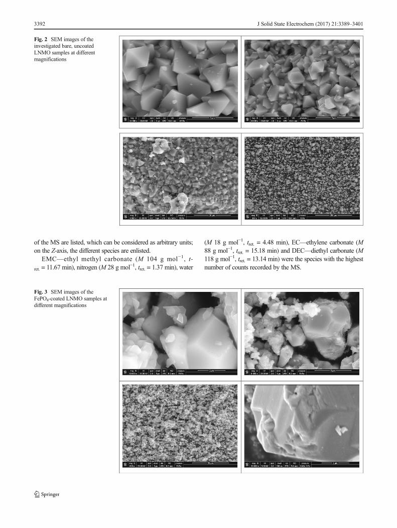
Figure 2 shows SEM images of the uncoated, and Fig. 3shows SEM images of the coated LNMO sample. The particlesare of a polygonal appearance, densely packed and based on anoctahedral structure. The FePO4 coating is visible as a brighterlayer in contrast to the darker base material. The coating is,however, not totally homogeneously distributed; uncoated parti-cles are clearly visible.
Using EDXmeasurements, the coatingwas further investigat-ed, see Fig. 4. The Fe is hard to discern as its peaks appear asshoulders beside the major Mn peaks. P with its peak at 2 keV,however, is a good indicator for the coating. The investigationsshow that the FePO4 is of a crystalline character, and confirm thatthe particles are not totally covered.
The particle size of the LNMOwasmeasured by laser diffrac-tion analysis, d(0.9) being 11.2μmand d(0.5) being 5.1μm. TheBETsurface area of the samples was 1.2 m2 g−1 for the uncoatedstarting material and 10.0 m2 g−1 for the FePO4-coated LNMO,which was a surprisingly high value.
The electrochemical properties of the LNMO were improvedby the FePO4 coating as shown in Fig. 5. Irreversible capacitylosses in the first cycle were smaller, capacity retention improvedand rate capability was enhanced.
Interestingly, the cyclovoltammograms of the coated LNMOmaterial showed a suppressed current in the first cycle. However,after activation, the capacity is again more stable than that of thepristine LNMO, see Fig. 6.
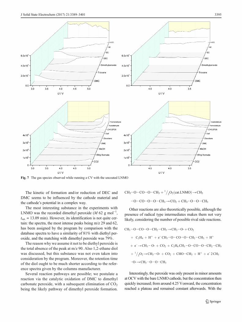
The gas species which evolved due to reactions between thecathode and the electrolyte while running a CVare visualised inFig. 7 for the uncoated LNMO and in Fig. 8 for the FePO4-coated material.
Only the data of the first cycle are used; the species observedin high concentrations are summarised in the upper two dia-grams, while the substances that were detected in low amountscan be found below. The diagrams on the left show the resultswhen the voltage of the CV ran from OCV up to 5.0 V; thediagrams on the right show the results when the potential wasdecreased from5.0 down to 3.5Vagain. On theY-axis, the counts
Fig. 1 XRD diffraction pattern ofthe uncoated starting material andthe LNMO sample coated withFePO4. The peaks indicated withasterisks (*) are due to rock salt(LiNiOx) type impurities
J Solid State Electrochem (2017) 21:3389–3401 3391
of the MS are listed, which can be considered as arbitrary units;on the Z-axis, the different species are enlisted.
EMC—ethyl methyl carbonate (M 104 g mol−1, t-ret. = 11.67 min), nitrogen (M 28 g mol−1, tret. = 1.37 min), water
(M 18 g mol−1, tret. = 4.48 min), EC—ethylene carbonate (M88 g mol−1, tret. = 15.18 min) and DEC—diethyl carbonate (M118 g mol−1, tret. = 13.14 min) were the species with the highestnumber of counts recorded by the MS.
Fig. 2 SEM images of theinvestigated bare, uncoatedLNMO samples at differentmagnifications
Fig. 3 SEM images of theFePO4-coated LNMO samples atdifferent magnifications
3392 J Solid State Electrochem (2017) 21:3389–3401
EMC, like ethanol (M 46 gmol−1, tret. = 7.93min) and acetone(M 58 g mol−1, tret. = 8.72 min), was eliminated from the charts.EMC was eliminated as it was appearing in such concentrationsit would have required another scale to be visualised; ethanol andacetone, because they were used for cleaning the cells and tub-ings and therefore can be considered as an experimental artefact.For this reason, the ethanol from the decomposition of the elec-trolyte could not be singled out in these experiments.
The nitrogen found represents the limitations of the ex-perimental setup, as the sum of all leakages from the cells,
from the connections and from the GC/MS. The amount ofnitrogen in the diagrams is not directly comparable with theother substances, as the potential of the detector during thefirst minutes of each measurement has been reduced to pro-tect the device from possible damage by an overload (t = 1–1.75 min gain = 0.95; from 1.75 min on gain = 1.62); thus,the nitrogen is only detected at approx. 30% of its realconcentration.
The water content observed in the course of the experimentswas surprisingly high. As nitrogen, water is an indicator of the
Fig. 4 SEM image (top) withEDX results, position 1 (middle)and 2 (bottom), of the FePO4-coated LNMO sample
J Solid State Electrochem (2017) 21:3389–3401 3393
tightness of the cells and the whole experimental setup.Also, there are some water traces in the carrier gas(He), and there are some residues from the cleaning ofthe cells. The electrolyte contains some traces of water,and the cathode and separator also add some residues.The contribution of each source of water cannot beestimated; water from other sources than the electrolyteis therefore a nuisance factor for the experiments whichis to be eliminated as much as possible in the future.
Interestingly, the concentration of observed water wasnot constant, but showed a dependency on the cathode’spotential. With rising potential, the water content re-corded by the GC/MS decreased, and with decreasingpotential, it slowly increased again afterwards. This in-dicates the occurrence of reactions which generate andconsume water, the reactions depending on the cath-ode’s potential.
The concentration of EC in the experiments showed a ten-dency towards increasing over time; according to the data,there is no dependency on the potential. Also, the type ofcathode had no influence on the development of the ECconcentration.
Of the species formed in the course of the experiments, DECand DMC—dimethyl carbonate (M 90 g mol−1, t-ret. = 10.39 min)—were present in the highest concentrations,apart from native electrolyte components or impurities.
Although it is well known that these species are formed byrearrangement of EMC [21], the mechanism of the cathode’sinfluence on the concentration of the carbonates is not knownyet, however.
2EMC⇄DEC þ DMC
DEC and DMC were present with the same starting con-centrations, independent of the LNMO used as cathode. Withthe uncoated LNMO, the concentration of both species de-creased over time, following an exponential behaviour (whichis due to the gas flow), with a small increase at high potentialsoverlaying this general decrease. The potential threshold fromwhich onward the concentration of the carbonates began torise again could not be estimated.
With the FePO4-coated LNMO, only the DMC concentra-tion decreased over time; however, in a much more delayedmanner, but the concentration of DEC remained constant atstarting concentration.
Fig. 5 Cycling performance at various C-rates of the uncoated pristine LNMO (left) and the FePO4-coated sample (right)
Fig. 6 Cycling voltammograms of the uncoated pristine LNMO (left) and the FePO4-coated sample (right)
3394 J Solid State Electrochem (2017) 21:3389–3401
The kinetic of formation and/or reduction of DEC andDMC seems to be influenced by the cathode material andthe cathode’s potential in a complex way.
The most interesting substance in the experiments withLNMO was the recorded dimethyl peroxide (M 62 g mol−1,tret. = 13.09 min). However, its identification is not quite cer-tain: the spectra, the most intense peaks being m/z 29 and 62,has been assigned by the program by comparison with thedatabase spectra to have a similarity of 81% with diethyl per-oxide, and the matching with dimethyl peroxide was 79%.
The reason why we assume it not to be diethyl peroxide isthe total absence of the peak at m/z 90. Also 1,2-ethane diolwas discussed, but this substance was not even taken intoconsideration by the program. Moreover, the retention timeof the diol ought to be much shorter according to the refer-ence spectra given by the columns manufacturer.
Several reaction pathways are possible; we postulate areaction via the catalytic oxidation of DMC to dimethylcarbonate peroxide, with a subsequent elimination of CO2
being the likely pathway of dimethyl peroxide formation.
CH3−O−CO−O−CH3 þ 1�2O2 cat:LNMOð Þ→CH3
−O−CO−O−O−CH3→CO2 þ CH3−O−O−CH3
Other reactions are also theoretically possible, although thepresence of radical type intermediates makes them not verylikely, considering the number of possible rival side reactions.
CH3 −O−CO−O−CH2 −CH3→CH3 −O⋅þ CO2
þ C2H4 þ Hþ þ e− CH3 −O−CO−O−CH2 −CH3 þ Hþ
þ e−→CH3 − O⋅ þ CO2 þ C2H6 CH3 −O−CO−O−CH2 −CH3
þ 1�2O2→CH3 −O⋅ þ CO2 þ CHO−CH3 þ Hþ þ e− 2CH3
−O⋅→CH3 −O−O−CH3
Interestingly, the peroxide was only present in minor amountsat OCVwith the bare LNMOcathode, but the concentration thenquickly increased; from around 4.25Vonward, the concentrationreached a plateau and remained constant afterwards. With the
Fig. 7 The gas species observed while running a CV with the uncoated LNMO
J Solid State Electrochem (2017) 21:3389–3401 3395
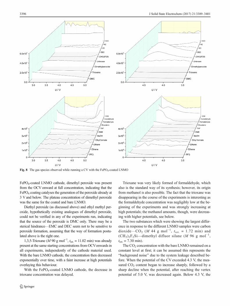
FePO4-coated LNMO cathode, dimethyl peroxide was presentfrom the OCVonward at full concentration, indicating that theFePO4 coating catalyses the generation of the peroxide already at3 V and below. The plateau concentration of dimethyl peroxidewas the same for the coated and bare LNMO.
Diethyl peroxide (as discussed above) and ethyl methyl per-oxide, hypothetically existing analogues of dimethyl peroxide,could not be verified in any of the experiments run, indicatingthat the source of the peroxide is DMC only. There may be asterical hindrance—EMC and DEC seem not to be sensitive toperoxide formation, assuming that the way of formation postu-lated above is the right one.
1,3,5-Trioxane (M 90 g mol−1, tret. = 11.02 min) was alreadypresent at the same starting concentrations fromOCVonwards inall experiments, independently of the cathode material used.With the bare LNMO cathode, the concentration then decreasedexponentially over time, with a faint increase at high potentialsoverlaying this behaviour.
With the FePO4-coated LNMO cathode, the decrease intrioxane concentration was delayed.
Trioxane was very likely formed of formaldehyde, whichalso is the standard way of its synthesis; however, its originfrom methanol is also possible. The fact that the trioxane wasdisappearing in the course of the experiments is interesting asthe formaldehyde concentration was negligibly low at the be-ginning of the experiments and was strongly increasing athigh potentials; the methanol amounts, though, were decreas-ing with higher potentials, see below.
The two substances which were showing the largest differ-ence in response to the different LNMO samples were carbondioxide—CO2 (M 44 g mol−1, tret. = 1.72 min) and(CH3)2F2Si—dimethyl difluor silane (M 96 g mol−1,tret. = 7.30 min).
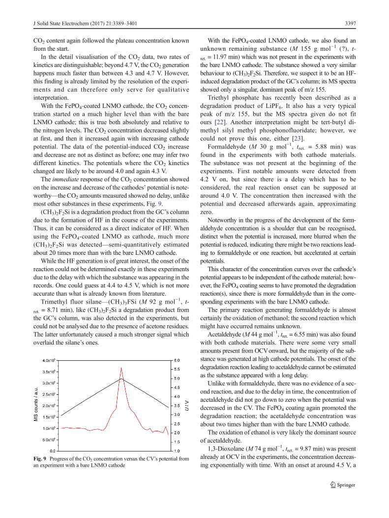
The CO2 concentration with the bare LNMO remained on aconstant level at first; it can be assumed this represents theBbackground noise^ due to the system leakage described be-fore. When the potential of the CV exceeded 4.3 V, the mea-sured CO2 content began to increase sharply, followed by asharp decline when the potential, after reaching the vertexpotential of 5.0 V, was decreased again. Below 4.3 V, the
Fig. 8 The gas species observed while running a CV with the FePO4-coated LNMO
3396 J Solid State Electrochem (2017) 21:3389–3401
CO2 content again followed the plateau concentration knownfrom the start.
In the detail visualisation of the CO2 data, two rates ofkinetics are distinguishable; beyond 4.7 V, the CO2 generationhappens much faster than between 4.3 and 4.7 V. However,this finding is already limited by the resolution of the experi-ments and can therefore only serve for qualitativeinterpretation.
With the FePO4-coated LNMO cathode, the CO2 concen-tration started on a much higher level than with the bareLNMO cathode; this is true both absolutely and relative tothe nitrogen levels. The CO2 concentration decreased slightlyat first, and then it increased again with increasing cathodepotential. The data of the potential-induced CO2 increaseand decrease are not as distinct as before; one may infer twodifferent kinetics. The potentials where the CO2 kineticschanged are likely to be around 4.0 and again 4.3 V.
The immediate response of the CO2 concentration showedon the increase and decrease of the cathodes’ potential is note-worthy—the CO2 amounts measured showed no delay, unlikemost other substances in these experiments, Fig. 9.
(CH3)2F2Si is a degradation product from the GC’s columndue to the formation of HF in the course of the experiments.Thus, it can be considered as a direct indicator of HF. Whenusing the FePO4-coated LNMO as cathode, much more(CH3)2F2Si was detected—semi-quantitatively estimatedabout 20 times more than with the bare LNMO cathode.
While the HF generation is of great interest, the onset of thereaction could not be determined exactly in these experimentsdue to the delay with which the substance was appearing in therecords. One could guess at 4.4 to 4.5 V, which is not moreaccurate than what is already known from literature.
Trimethyl fluor silane—(CH3)3FSi (M 92 g mol−1, t-ret. = 8.71 min), like (CH3)2F2Si a degradation product fromthe GC’s column, was also detected in the experiments, butcould not be analysed due to the presence of acetone residues.The latter unfortunately caused a much stronger signal whichoverlaid the silane’s ones.
With the FePO4-coated LNMO cathode, we also found anunknown remaining substance (M 155 g mol−1 (?), t-ret. = 11.97 min) which was not present in the experiments withthe bare LNMO cathode. The substance showed a very similarbehaviour to (CH3)2F2Si. Therefore, we suspect it to be an HF-induced degradation product of the GC’s column; its MS spectrashowed only a singular, dominant peak of m/z 155.
Triethyl phosphate has recently been described as adegradation product of LiPF6. It also has a very typicalpeak of m/z 155, but the MS spectra given do not fitours [22]. Another interpretation might be tert-butyl di-methyl silyl methyl phosphonofluoridate; however, wecould not prove this one, either [23].
Formaldehyde (M 30 g mol−1, tret. = 5.88 min) wasfound in the experiments with both cathode materials.The substance was not present at the beginning of theexperiments. First notable amounts were detected from4.2 V on, but since there is a delay which has to beconsidered, the real reaction onset can be supposed ataround 4.0 V. The concentration then increased with thepotential and decreased afterwards again, approximatingzero.
Noteworthy in the progress of the development of the form-aldehyde concentration is a shoulder that can be recognised,distinct when the potential is increased, more blurred when thepotential is reduced, indicating there might be two reactions lead-ing to formaldehyde or one reaction, but accelerated at certainpotentials.
This character of the concentration curves over the cathode’spotential appears to be independent of the cathodematerial; how-ever, the FePO4 coating seems to have promoted the degradationreaction(s), since there is more formaldehyde than in the corre-sponding experiments with the bare LNMO cathode.
The primary reaction generating formaldehyde is almostcertainly the oxidation of methanol; the second reaction whichmight have occurred remains unknown.
Acetaldehyde (M 44 g mol−1, tret. = 6.55 min) was also foundwith both cathode materials. There were some very smallamounts present from OCVonward, but the majority of the sub-stance was generated at high cathode potentials. The onset of thedegradation reaction leading to acetaldehyde cannot be estimatedas the substance appeared with a long delay.
Unlike with formaldehyde, there was no evidence of a sec-ond reaction, and due to the delay in time, the concentration ofacetaldehyde did not go down to zero when the potential wasdecreased in the CV. The FePO4 coating again promoted thedegradation reaction; the acetaldehyde concentration wasabout two times higher than with the bare LNMO cathode.
The oxidation of ethanol is very likely the dominant sourceof acetaldehyde.
1,3-Dioxolane (M 74 g mol−1, tret. = 9.87 min) was presentalready at OCV in the experiments, the concentration decreas-ing exponentially with time. With an onset at around 4.5 V, a
Fig. 9 Progress of the CO2 concentration versus the CV’s potential froman experiment with a bare LNMO cathode
J Solid State Electrochem (2017) 21:3389–3401 3397
slight increase was overlying the generally decreasing concen-tration profile.
This behaviour was the same for both cathode materials,but with the FePO4-coated LNMO, the 1,3-dioxolane follow-ed a two-time higher concentration profile.
Although frequently used as electrolyte solvent, 1,3-dioxolane has to the best of our knowledge not been describedas a decomposition product so far [1, 24, 25]. The chemistry ofthe compound and its presence already at the beginning of theexperiments indicate an origin from a reaction on the lithiumanode; however, the observed dependency on high cathodepotentials is strange. A mechanism based on a reduction anda subsequent nucleophilic reaction as described by G. Gachotet al. [26] is proposed.
EC þ e−→O −−CH2 −CH2 −O−C⋅
¼ OO−−CH2 −CH2 −O−C⋅
¼ O þ CH2O→ 1; 3−dioxolane þ CO2 þ e−
The EC ring is opened by a reduction, and the intermediatesubstance, or the diol resulting after the addition of water andthe removal of CO2, reacts with formaldehyde. Via a hemiac-etal, 1,3-dioxolane is finally formed. The reactions may ormay not be catalysed by the lithium ions via lithium alkoxidesor traces of HF.
The observed absence of formaldehyde at OCV, in contrastto the present acetaldehyde, could be explained by this reac-tion which consumes all formaldehyde formed at the cathode.When at high potentials, formaldehyde is then generated inhigher quantities, and the dioxolane concentration again in-creases for a while, until the formaldehyde supply runs out dueto the decreasing cathode potential. All these mechanisms aredominated by the experimental gas flow which causes theobserved 1,3-dioxolane decrease over time, see Fig. 10.
THF, tetrahydrofuran (M 72 g mol−1, tret. = 10.34 min), wasalso present from OCVon, its concentration decreasing withtime. A dependency on the cathode’s potential as for the 1,3-
dioxolane above could neither be confirmed nor refuted withthe available data. Although the illustrated experiments are notshowing it clearly, the concentration can be considered thesame for both cathode materials.
Although at times used as electrolyte component [1, 27],THF has also been mentioned as degradation product found inlithium-ion electrolytes [23]. To the best of our knowledge, noreaction pathways explaining its presence have been pub-lished yet.
The properties observed in the course of the experimentsindicate formation on the lithium anode. The formulation of areaction of a C4 compound is tricky, as there were no startingmaterials based on C4 units. As no C3 compounds were foundin the measurements, assuming an EC origin seems more log-ical than a reaction based on one of the linear carbonates EMC(DEC or DMC), from which C3-based substances could alsobe expected.
For the further postulation of a mechanism, it is necessaryto elaborate at some length. The SEI formed on the anodesurface has been found to consist of a dense inorganic layerand a second more porous organic layer, the latter mainlyconsisting of polyethylene glycol oligomers formed of ECmolecules (or polypropylene glycol when PC is used).Several glycol units, differing by their end groups, are con-densed together. Carbonate, alkoxyl, hydroxyl and phosphategroups have been reported, see Fig. 11 [28–30].
Based on the end groups, a classification has beenestablished, and different formation mechanisms have beenpublished. A transesterification was proposed, a start fromalkoxides has been described and a PF5 (Lewis acid) support-ed mechanism has also been published on [30–33].
On the basis of these reaction mechanisms, we propose areaction in which a CO3
−2 ion is eliminated instead of CO2 bya rearrangement, lithium ions likely stabilising the carbonateion formed, see Fig. 12.
The absence of C6 components indicates that the C4 unitwill quickly undergo a ring closing reaction to form furan, orthat THF is rather stable and does not further participate inother reactions. For the nature of the end groups, it can besuspected that they are of a rather small size.
Methanol (M 32 gmol−1, tret. = 6.32min) was present in theexperiments in very small amounts from OCVon the concen-tration decreasing both with time and with rising cathode po-tential. With decreasing potential, the concentration began torise again faintly, indicating a methanol consuming reaction athigher potentials, and that there is a continuous supply by a
Fig. 10 Progress of the 1,3-dioxolane concentration versus the CV’spotential from an experiment with a bare LNMO cathode
Fig. 11 General formula of the polyethylene-based oligomers found inan SEI [30]
3398 J Solid State Electrochem (2017) 21:3389–3401
second reaction on a very small scale. The concentration andits profile were the same for both cathode materials.
The potential dependency is likely explained with an oxida-tion of methanol to formaldehyde; while the supplying reaction,which also explains the methanol present at the start of the ex-periments, is the hydrolysis of EMC (DMC), catalysed by HFand traces of water.
Ethyl formate (M 74 g mol−1, tret. = 9.11 min) wasgenerated in very small amounts at higher potentials,though the substance was appearing with a delay; there-fore, the onset potential of the formation reaction cannotbe estimated. The FePO4 coating was catalysing thereaction, so there was more ethyl formate with thiscathode material than with the other.
The mechanism leading to formation of this substance re-mains unclear. An anodic reaction pathway has been proposedbyGachot et al. [26]. However, an anodic reaction is not likelyfor these experiments, as there is a dependency on the cathodepotential and another one on the cathode material. A forma-tion from ethanol, or its lithium alkoxide reacting with form-aldehyde, the resulting hemiacetal then further being oxidised,could explain the formation of ethyl formate.
This reaction pathway, however, is not quite satisfactory asnomethyl formate was found in any of the experiments; on theother hand, ethanol, as explained above, was present in muchhigher amounts than methanol. We would also have expectedsome ethyl acetate and methyl acetate; however, only the latterwas found at least in traces.
1,2-Dimethoxy ethane,DME (M90gmol−1, tret. = 11.18min),behaved similarly to THF. It was present from OCVon the con-centration decreasing over time. There seems to have been nodependency on the cathode potential nor on the cathode materialused.
The lack of dependencies and the presence already at thestart of the experiments indicate an origin not based on thecathode side. An anodic reaction on the lithium side is obvi-ous; a convincing reaction mechanism has been described byGachot et al. [26].
Surprisingly, no ethane diol and also no 1,4-dioxane werefound in any of the experiments run with LNMO samples. Wesuspect that ethane diol is only an intermediate and therefore isconsumed by other reactions rather quickly. 1,4-Dioxane hasbeen described as an anodic product; it remains unclearwhether this substance has not been formed at all or whetherthe compound has been oxidised on the cathode—whichwould raise the question why it should be less stable than1,3-dioxolane or 1,3,5-trioxane.
Phosphor trifluoride, PF3 (M 88 g mol−1, tret. = 2.10 min),could only be detected in very small amounts in combinationwith the FePO4-coated LNMO and at very high potentials.The onset of the degradation reaction leading to PF3 is esti-mated to occur at 4.5 to 4.6 V.
The formulation of a reaction explaining PF3 as an oxida-tive reaction product is difficult; one could assume it is theside product of a degradation reaction of LiPF6 and the FePO4
coating.Ethane (M 30 g mol−1, tret. = 2.78 min) and ethene (M
28 g mol−1, tret. = 2.28 min) could only be detected in verysmall amounts and after the cathode reached high potentials.The concentration increased with a long delay; the FePO4-coated material generated about three times more of thesesubstances than the bare LNMO cathode.
In literature, the hydrocarbons have been said to originatefrom reductive mechanisms or oxidative degradation mecha-nisms [20, 34, 35]; in our experiments, the latter ought toapply.
Traces of methyl acetate (M 74 g mol−1, tret. = 9.17 min)and 2-methyl-1,3-dioxolane (M 88 g mol−1, tret. = 10.86 min)could be detected in some experiments, though due to thesmall amounts, it is not possible to determine a dependencyof these substances’ formation on the cathode’s potential ormaterial.
A good explanation for the reductive formation of thesesubstances has again been given by Gachot et al. [26].
Summary and conclusions
Two LNMO samples, one bare and one with a coating ofFePO4, were electrochemically characterised, and the degra-dat ion products formed during the running of acyclovoltammetric experiment were investigated with a GC/MS combination. The development of the concentrations wasdetermined online and visualised for better evaluation.
Using 1 M LiPF6, EC:EMC = 3:7, 2% FEC as electrolyte,carbon dioxide, dimethyl peroxide, 1,3,5-trioxane, 1,2-dimethoxy ethane, acetaldehyde, THF, dimethyl difluor silaneand other compounds were found. Where degradation path-ways were unknown, new ones were suggested.
The degradation products found in the course of the exper-iments with the LNMO samples were in part surprising;
Fig. 12 Proposed reaction for the formation of a C4 unit by two ethyleneglycol units by a rearrangement and elimination of a CO3
−2 ion
J Solid State Electrochem (2017) 21:3389–3401 3399
however, it is almost more surprising how many of the degra-dation products described in the relevant literature did notappear in our measuring campaigns. The cathode materialseems to have a significant influence on electrolytedecomposition.
Measuring the development of the concentration of thedecomposition products over time and correlating the concen-trations with the CV’s potential though has been found to givevaluable insights into the reactions occurring.
Acknowledgements The measurements and results described in thispaper were generated in the course of the eCaiman project which wasgenerously co-funded under the H2020 framework by the EuropeanUnion.
Open Access This article is distributed under the terms of the CreativeCommons At t r ibut ion 4 .0 In te rna t ional License (h t tp : / /creativecommons.org/licenses/by/4.0/), which permits unrestricted use,distribution, and reproduction in any medium, provided you give appro-priate credit to the original author(s) and the source, provide a link to theCreative Commons license, and indicate if changes were made.
References
1. Daniel C, Besenhard JO (eds) (2011) Handbook of batterymaterials2nd edition. Wiley-VCH, Weinheim
2. Thackeray MM, Johnson CS, Vaughey JT, Li N, Hackney SA(2005) Advances in manganese-oxide Bcomposite^ electrodes forlithium-ion batteries. J Mater Chem 15:2257–2267
3. Croy JR, Park JS, Shin Y, Yonemoto BT, Balasubramanian M,Long BR, Ren Y, Thackeray MM (2016) Prospects for spinel-sta-bilized, high-capacity lithium-ion battery cathodes. J PowerSources 334:213–220
4. Padhi AK, Nanjundaswamy KS, Goodenough JB (1997) Phospho-olivines as positive-electrodematerials for rechargeable lithium bat-teries. J Electrochem Soc 144:1188–1194
5. Amine K, Yasuda H, Yamachi M (2000) Olivine LiCoPO4 as 4.8 Velectrode material for lithium batteries. Electrochem Solid-StateLett 3:178–179
6. Axmann P, Stinner C (2009) Positive electrode: high-voltage mate-rials. In: Garche J, Dyer C, Moseley P, Ogumi Z, Rand D, ScrosatiB (eds) Encyclopedia of electrochemical power sources, vol 5.Elsevier, Amsterdam Boston Heidelberg London New YorkOxford Paris San Diego San Francisco Singapore Sydney Tokyo,pp 237–242
7. Zhong Q, Bonakdarpour A, Zhang M, Gao Y, Dahn JR (1997)Synthesis and electrochemistry of LiNixMn2−xO4. J ElectrochemSoc 144:205–213
8. Ohzuku T, Takeda S, Iwanaga M (1999) Solid-state redox poten-tials for Li[Me1/2Mn3/2]O4 (Me: 3d-transition metal) having spinel-framework structures: a series of 5 volt materials for advancedlithium-ion batteries. J Power Sources 81–82:90–94
10. Yi T-F, Mei J, Zhu Y-R (2016) Key strategies for enhancing thecycling stability and rate capacity of LiNi0.5Mn1.5O4 as high-voltage cathode materials for high power lithium-ion batteries. JPower Sources 316:85–105
11. Axmann P, Gabrielli G, Wohlfahrt-Mehrens M (2016) Tailoringhigh-voltage and high-performance LiNi0.5Mn1.5O4 cathode mate-rial for high energy lithium-ion batteries. J Power Sources 301:151–159
12. Choi N-S, Han J-G, Ha S-Y, Park I, Back C-K (2015) Recentadvances in the electrolytes for interfacial stability of high-voltagecathodes in lithium-ion batteries. RSC Adv 5:2732–2748
13. Xu M, Tsiouvaras N, Garsuch A, Gasteiger HA, Lucht BL (2014)Generation of cathode passivation films via oxidation of lithium bis(oxalate) borate on high voltage spinel (LiNi0.5Mn1.5O4). J PhysChem 118:7363–7368
14. Wang H, Rus E, Sakuraba T, Kikuchi J, Kiya Y, Abruña HD (2014)CO2 and O2 evolution at high voltage cathode materials of Li-ionbatteries: a differential electrochemical mass spectrometry study.Anal Chem 86:6197–6201
15. Kulova TL, Skundin AM (2016) High-voltage materials for posi-tive electrodes of lithium ion batteries (review). RUSS JELECTROCHEM+ 52:501:524
16. Qian Y, Schultz C, Niehoff P, Schwieters T, Nowak S,Schappacher FM, Winter M (2016) Investigations on theelectrochemical decomposition of the electrolyte additivevinylene carbonate in Li metal half cells and lithium ionfull cells. J Power Sources 332:60–71
17. Xia J, Dahn JR (2016) Improving sulfolane-based electrolyte forhigh voltage Li-ion cells with electrolyte additives. J Power Sources324:704–711
18. Imholt L, Röser S, Börner M, Streipert B, Rad BR, Winter M,Cekic-Laskovica I (2017) Trimethylsiloxy based metal complexesas electrolyte additives for high voltage application in lithium ioncells. Electrochim Acta 235:332–339
19. Yong T, Zhang L, Wang J, Mai Y, Yan X, Zhao X (2016) Novelcholine-based ionic liquids as safe electrolytes for high-voltage lith-ium-ion batteries. J Power Sources 328:397–404
20. Gachot G, Ribiere P, Mathiron D, Grugeon S, Armand M, LericheJ-B, Pilard S, Laruelle S (2011) Gas chromatography/mass spec-trometry as a suitable tool for the Li-ion battery electrolyte degra-dation mechanisms study. Anal Chem 83:478–485
21. Takeuchi ES, Gan H, Palazzo M, Leising RA, Davis SM(1997) Anode passivation and electrolyte solvent dispropor-tionation: mechanism of ester exchange reaction in lithium-ion batteries. J Electrochem Soc 144:1944–1948
22. Weber W, Kraft V, Grützke M, Wagner R, Winter M, Nowak S(2015) Identification of alkylated phosphates by gas chromatogra-phy–mass spectrometric investigations with different ionizationprinciples of a thermally aged commercial lithium ion battery elec-trolyte. J Chromatogr A 1394:128–136
23. AmonA (2014) Gas evolution from lithium ion batteries studied in-situ by coupled GC/MS-FTIR. Master Thesis Vienna University,Vienna
24. Pang C, Ding F, SunW, Liu J, HaoM,Wang Y, Liu X, Xu Q (2015)A novel dimethyl sulfoxide/1,3-dioxolane based electrolyte forlithium/carbon fluorides batteries with a high discharge voltageplateau. Electrochim Acta 174:230–237
25. Suo L, Hu Y-S, Li H, Armand M, Chen L (2013) A new class ofsolvent-in-salt electrolyte for high-energy rechargeable metalliclithium batteries. Nat Commun 4:1481
26. Gachot G, Grugeon S, Eshetu GG, Mathiron D, Ribière P, ArmandM, Laruelle S (2012) Thermal behaviour of the lithiated-graphite/electrolyte interface throughGC/MS analysis. ElectrochimActa 83:402–409
27. XuW, Wang J, Ding F, Chen X, Nasybulin E, Zhang Y, Zhang J-G(2014) Lithium metal anodes for rechargeable batteries. EnergyEnviron Sci 7:513–537
28. Edström K, Herstedt M, Abraham DP (2006) A new look at thesolid electrolyte interphase on graphite anodes in Li-ion batteries. JPower Sources 153:380–384
3400 J Solid State Electrochem (2017) 21:3389–3401
29. Laruelle S, Pilard S, Guenot P, Grugeon S, Tarascon J-M (2004)Identification of Li-based electrolyte degradation products throughDEI and ESI high-resolution mass spectrometry. J Electrochem Soc151:A1202–A1209
30. Gachot G, Grugeon S, Armand M, Pilard S, Guenot P, Tarascon J-M, Laruelle S (2008) Deciphering the multi-step degradation mech-anisms of carbonate-based electrolyte in Li batteries. J PowerSources 178:409–421
31. Yoshida H, Fukunaga T, Hazama T, Terasaki M, Mizutani M,Yamachi M (1997) Degradation mechanism of alkyl carbonate sol-vents used in lithium-ion cells during initial charging. J PowerSources 68:311–315
32. Sloop SE, Kerr JB, Kinoshita K (2003) The role of Li-ion batteryelectrolyte reactivity in performance decline and self-discharge. JPower Sources 119–121:330–337
33. Sasaki T, Abe T, Iriyama Y, Inaba M, Ogumi Z (2005) Formationmechanism of alkyl dicarbonates in Li-ion cells. J Power Sources150:208–215
34. Shin J-S, Han C-H, Jung U-H, Lee S-I, Kim H-J, Kim K (2002)Effect of Li2CO3 additive on gas generation in lithium-ion batteries.J Power Sources 109:47–52
35. Kong W, Li H, Huang X, Chen L (2005) Gas evolution behaviorsfor several cathode materials in lithium-ion batteries. J PowerSources 142:285–291
J Solid State Electrochem (2017) 21:3389–3401 3401