23
ANSYS Element Sl ti Selection eLearning Peter Barrett October 2012 © 2012 CAE Associates Inc. and ANSYS Inc. All rights reserved.

ANSYS Element S l ti Selection eLearning
Peter BarrettOctober 2012
© 2012 CAE Associates Inc. and ANSYS Inc. All rights reserved.

ANSYS Element Selection
What is the best element type(s) for my analysis?yp ( ) y y— Best Answer - It depends!
What is the goal of the analysis?What is the goal of the analysis?— Displacements, temperatures, mode shapes, nominal strength, fatigue life,
stresses from fluid structure interaction, etc.
What are the shapes of my parts/assembly?— What types of symmetry can I take advantage of?— Is it long and slender where beams might be useful?Is it long and slender where beams might be useful?— Thin walled where Shell or Solid-Shell elements can be used?— Should I model the full assembly in one shot or use submodeling and/or
substructuring?g
What type of computational requirements are needed?— Linear vs. Nonlinear, Static vs. Dynamic, Time Domain vs. Freq. Domain?
2
Linear vs. Nonlinear, Static vs. Dynamic, Time Domain vs. Freq. Domain?• The more complex the analysis, the fewer elements can be effectively solved

ANSYS V11 – 186 Elements Available!
Note:Note:Some Beam, Pipe, Spar, Shell, Solid elements were removed or changed to legacyor changed to legacy after this release.
Although undocumented these elements remainthese elements remain in the code but require users to have access to V11 help or older documentation to use
3
documentation to use.

ANSYS V14 – 166 Elements Available!
Note:M l tMany new elements have been added since V11 including new surface effect and d d i iadvanced piping
elements
4
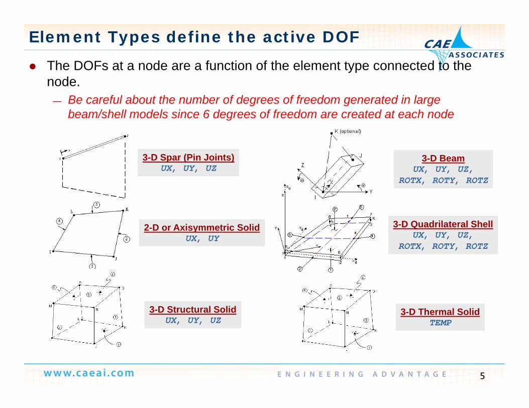
Element Types define the active DOF
The DOFs at a node are a function of the element type connected to the node.
— Be careful about the number of degrees of freedom generated in large beam/shell models since 6 degrees of freedom are created at each node
3-D Spar (Pin Joints)UX, UY, UZ
3-D BeamUX, UY, UZ,
ROTX ROTY ROTZROTX, ROTY, ROTZ
2-D or Axisymmetric Solid 3-D Quadrilateral Shell2 D or Axisymmetric SolidUX, UY UX, UY, UZ,
ROTX, ROTY, ROTZ
3-D Thermal SolidTEMP
3-D Structural SolidUX, UY, UZ
5

Element Shape Function
FEA solves for DOF values only at nodes FEA solves for DOF values only at nodes. An element shape function is the “shape” of the results within the
element.Most elements fall ithin t o categories Most elements fall within two categories:
— Linear or lower-order elements:• Corner or end nodes only.• Assume a linear variation of DOF values within element• Assume a linear variation of DOF values within element.
— (Using enhanced strain for quad/brick shapes will adds extra shapes for bending)• Only allows straight sides. Curves are faceted.
— Quadratic or higher-order:g• Corner or end nodes and mid-side nodes.• Assume a quadratic variation of DOFs within element.• Allows for modeling of curved boundaries
6
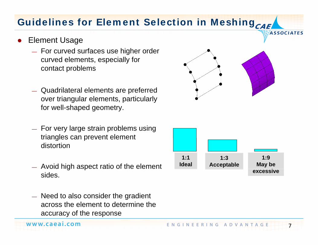
Guidelines for Element Selection in Meshing
Element Usage— For curved surfaces use higher order
curved elements, especially for contact problems
— Quadrilateral elements are preferred over triangular elements, particularly for well shaped geometryfor well-shaped geometry.
— For very large strain problems using triangles can prevent elementtriangles can prevent element distortion
— Avoid high aspect ratio of the element 1:9
May be 1:3
Acceptable1:1
Idealg psides.
— Need to also consider the gradient
excessive
7
across the element to determine the accuracy of the response

Define Element Types
Beam Elements:— Meshing of Line Bodies or Lines or through direct
node and element generation— Using a third node or orientation key point to orient— View “/ESHAPE” to check the X-sect orientation
Shell Elements:— Meshing of surface bodies / Areas— Element types controlled by assignment or
advanced mesh settings. Use consistent normals
Solid Element Midside Nodes:— Program controlled (default), dropped, or kept.
Element A Element B
8
Kept Dropped

Why Use Beam Elements? Advantages:
F t t l F ll B Th L lt d t F d t— Fast to solve, Follow Beam Theory, Less results data, Forces and moments and linearized stresses directly available
Disadvantages:C t t f l l t t ti M diffi lt t d fi Li it d— Cannot account for local stress concentrations, More difficult to define, Limited to constant or linear tapered cross-sections
Common ErrorsCross Section not oriented correctly— Cross-Section not oriented correctly
— Insufficient constraints when used in conjunction with shell and solid elements
9

Why Use Beam Elements? Common Modeling Issues
BEAM 188 KEYOPT(3) Sh f ti l th l th— BEAM 188: KEYOPT(3) Shape functions along the length:• 0 -- Linear (default) Recommend either 2 -- Quadratic or 3 -- Cubic (beam theory)• Mechanical defaults to Keyopt (3) = 2
BEAM 188/189 Section Controls— BEAM 188/189 Section Controls• The # of integration points in each cross section can greatly influence solution time
and results file size (Main Menu>Preprocessor>Sections>Beam>Common Sections > secdata)
• For linear materials use a coarse cross-section mesh; to capture plasticity a refined cross section mesh might be needed.
— Model connections correctly (Fully fixed vs. pinned vs. partial moment release)
10
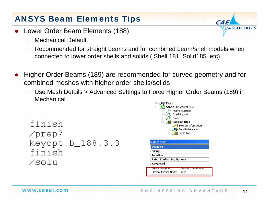
ANSYS Beam Elements Tips Lower Order Beam Elements (188)
M h i l D f lt— Mechanical Default— Recommended for straight beams and for combined beam/shell models when
connected to lower order shells and solids ( Shell 181, Solid185 etc)
Higher Order Beams (189) are recommended for curved geometry and for combined meshes with higher order shells/solids
Use Mesh Details > Advanced Settings to Force Higher Order Beams (189) in— Use Mesh Details > Advanced Settings to Force Higher Order Beams (189) in Mechanical
11

ANSYS Beam Elements Tips
Mechanical Spot Weld feature will automatically create beams and Mechanical Spot Weld feature will automatically create beams and “spiders” to spread the loading between bodies
Avoid connecting single beams directly to solids Avoid connecting single beams directly to solids— Use MPC contact, Constraint Equations or spokes to distribute the load— Spoke elements with lengths equal to half the member section is an preferred
modeling approachmodeling approach.
12

Why 2-d or Axisymmetric Solid Elements? Advantages:
Faster to Solve Less data created Easy to check / Evaluate stresses— Faster to Solve, Less data created, Easy to check / Evaluate stresses Disadvantages:
— Creating the 2-d surface and correct orientationModeling approximations of 3 d features— Modeling approximations of 3-d features
Common Errors— Not modeling @ z=0 with positive X for Radius
S l i i f l i (Pl S Pl S i A i i )— Selecting incorrect formulation (Plane Stress vs. Pl. Strain vs. Axisymmetric)
13
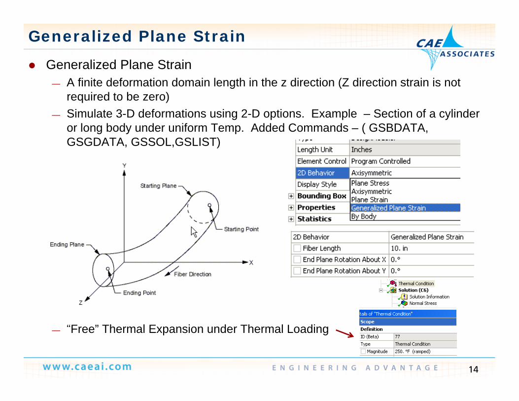
Generalized Plane Strain
Generalized Plane Strain— A finite deformation domain length in the z direction (Z direction strain is not
required to be zero) — Simulate 3-D deformations using 2-D options. Example – Section of a cylinder
l b d d if T Add d C d ( GSBDATAor long body under uniform Temp. Added Commands – ( GSBDATA, GSGDATA, GSSOL,GSLIST)
“Free” Thermal Expansion under Thermal Loading
14
— Free” Thermal Expansion under Thermal Loading

Why Use Shell Elements?
Advantages:— Faster to Solve, No length to thickness requirements, Less data created,
Forces and Moments easily obtained Disadvantages:
— Difficult to define contact, normal's and connections Common Errors
— Defining normal's inconsistentlyg y— Postprocessing the wrong surface
15

Why Use Shell Elements?
Common Modeling Issues— SHELL188: KEYOPT(3) Integration option:
• 0 -- Reduced integration with hourglass control (default)• 2 -- Recommend Full integration with incompatible modes• Mechanical defaults to Shell 181 - Keyopt (3) = 2
— Symmetry Boundary Conditions• Make sure to also constrain the in-plane rotations for symmetric surfaces
T L D fl ti O— Turn Large Deflection On• For Pressure loads large deflection is often required since membrane stiffness is not
accounted for with small deflections
16

Shell Elements Tips Lower Order Shell Elements (181) Mechanical Default
R d d f fl t b di d f bi d b / h ll d l h— Recommended for flat bodies and for combined beam/shell models when connected to lower order beams and solids ( Beam 188, Solid185 etc)
Higher Order Shells (281) are recommended for curved geometry and for Higher Order Shells (281) are recommended for curved geometry and for combined meshes with higher order beams/solids
— Use Mesh Details > Advanced Settings to Force Higher Order Shells (281) in MechanicalMechanical
17
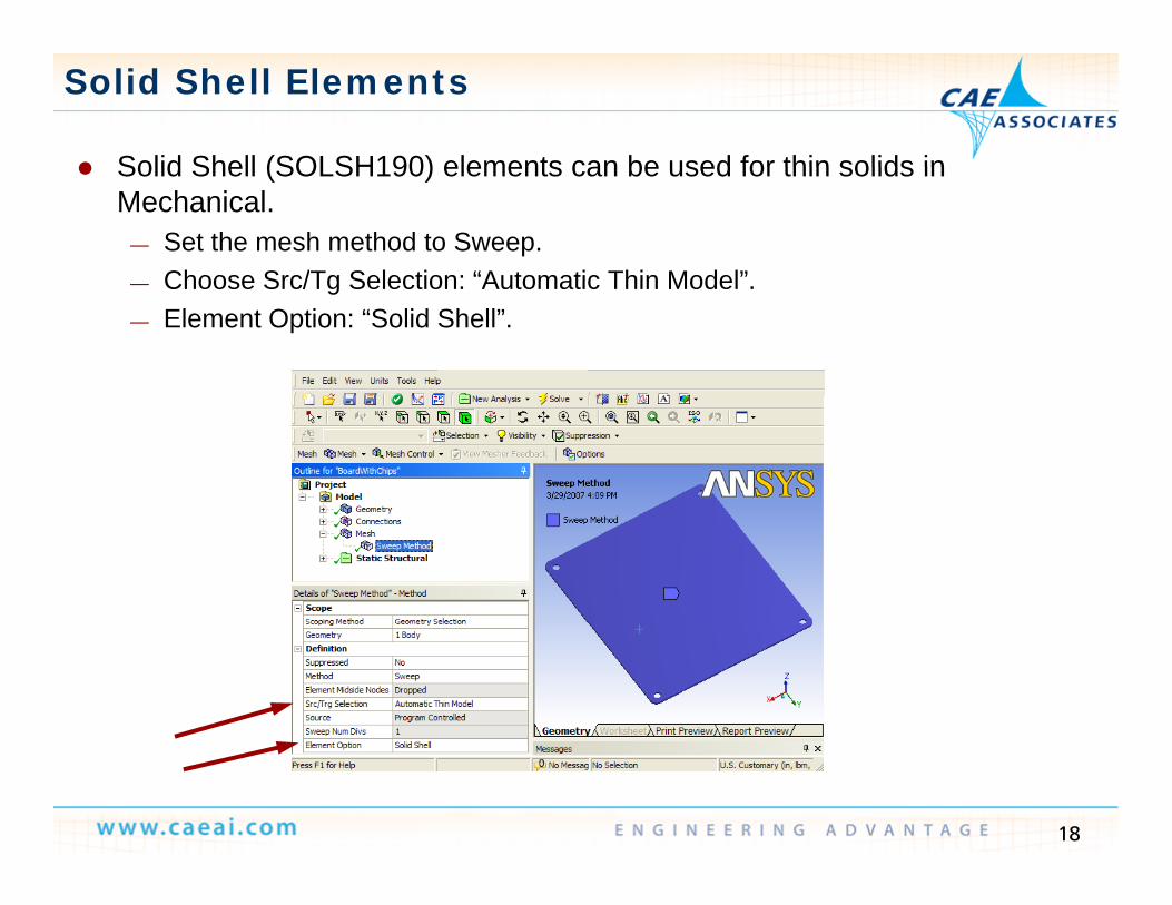
Solid Shell Elements
Solid Shell (SOLSH190) elements can be used for thin solids in Solid Shell (SOLSH190) elements can be used for thin solids in Mechanical.
— Set the mesh method to Sweep.Choose Src/Tg Selection: “Automatic Thin Model”— Choose Src/Tg Selection: Automatic Thin Model .
— Element Option: “Solid Shell”.
18

Why Use Solid Shell Elements? Advantages:
— Faster to Solve, No length to thickness requirements, Thickness defined by geometry, Auto Contact generation available, Easy transition to standard 3-d elements, Automatically creates tapered elements
Disadvantages: Disadvantages:— Sweepable Geometry and correct Element Orientation required
Common Errors— Defining normal's inconsistently. “Thin Section” must be in element Z direction
Common Modeling Issues— Lower Order Elements require refined mesh to modal small radii geometry— Meshing of complex geometry can be difficult
19

Why Use Solid Elements?
Advantages:— Easy to Model, Provides 3-d geometry with results, Can include stress
concentrations Disadvantages:
— Computationally expensive, For thin and slender bodies may require excessive element count
Common Errors— Using Singular results – stresses at sharp corners, fixed supports, point loads
Common Modeling Issues— SOLID185 (Lower Order Brick): KEYOPT(3) Element technology:( ) ( ) gy
• 0 -- Full integration with B-BAR method (default)• 1 -- Uniform reduced integration with hourglass control• 2 -- Enhanced strain formulation – Recommended for Bending Problems• 3 -- Simplified enhanced strain formulation• Mechanical defaults to Keyopt (3) = 0 when midside nodes are dropped
20

Mixed Order mesh transitions
ANSYS Mechanical Mixed Order Meshing
Mixed Order mesh transitions
Solid186Solid185
Brick
Solid186Brick w/ dropped
midnodes Solid186B i k
Solid186Brick w/ dropped
midnodesPyramid
Solid187
Brick Brick Solid186Pyramid
Solid187T tTet Tet
Edges of Meshed Volumes
Nodes
21
Elements (Side view of 1 row of elements from model above)
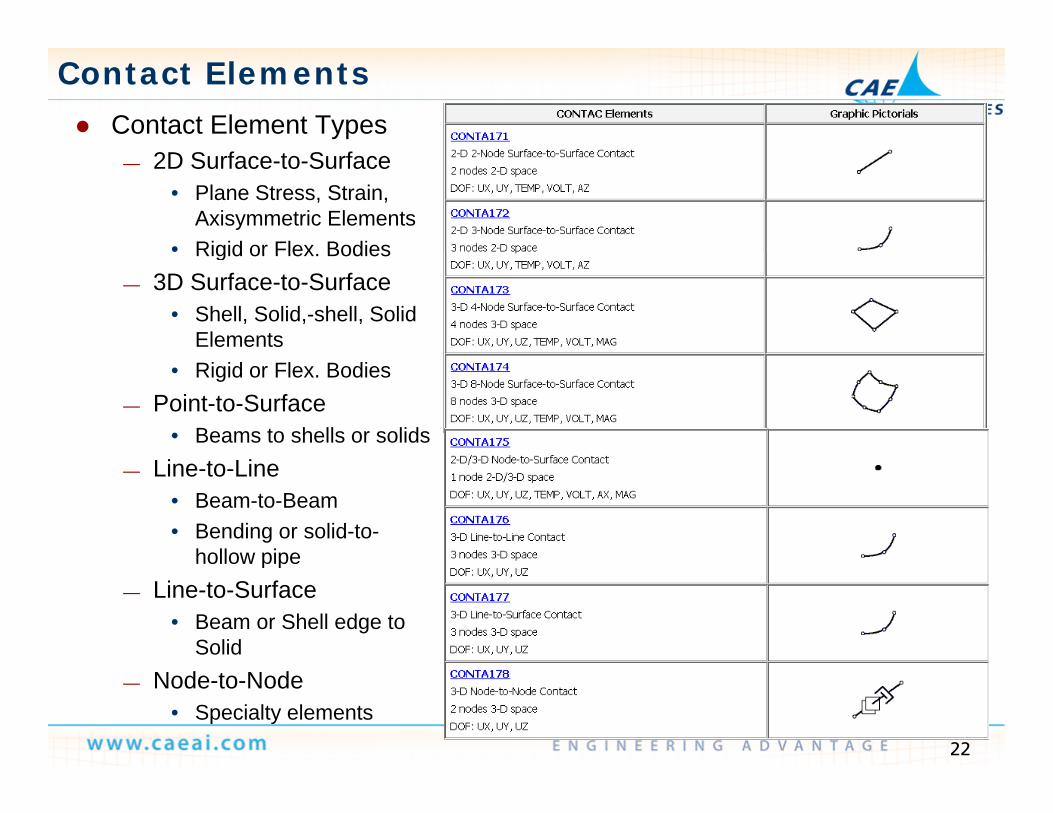
Contact Elements Contact Element Types
— 2D Surface-to-Surface• Plane Stress, Strain,
Axisymmetric Elements• Rigid or Flex BodiesRigid or Flex. Bodies
— 3D Surface-to-Surface• Shell, Solid,-shell, Solid
Elements• Rigid or Flex. Bodies
— Point-to-Surface• Beams to shells or solids
— Line-to-Line• Beam-to-Beam• Bending or solid-to-
hollow pipehollow pipe— Line-to-Surface
• Beam or Shell edge to Solid
22
— Node-to-Node• Specialty elements

Specialty Elements
Lumped Mass - Mass21— Keyopt defines DOF (6 by default)
• Set Keyopt 3=2 to reduce DOF if rotatry interia is not required
• Make sure to specify Mass in all threeMake sure to specify Mass in all three directions
Multi-Point Constraint - MPC184— Link, Slider, Revolute, Universal, Slot,
Point in plane Pin Cylindrical WeldPoint-in-plane, Pin, Cylindrical, Weld, Spherical, Screw, etc.
• Large deflection response• Automated Generation in WB
Bolt Pretension – PRETS179— Small deflection Only— Use MPC184 or contact surface offset
for large deflectionfor large deflection Spring - (Dashpot) Elements
— Combin14, 37, 39, 40, 214• Original Spring Elements
23
— Combin214• Unsymmetrical Stiffness/Damping


