Summary of Functions Control Monitor Brightness ✔ ✔ Contrast ✔ ✔ Audio ✔ ✔ Auto Adjust Video ✔ Restore Defaults ✔ Touch Controls On/Off ✔ ✔ Display Power On/Off ✔ ✔ Power-on Hours ✔ Backlight-on Hours ✔ Serial Number ✔ Command Set Supported by Device ✔ Large signage installations require a way to manage the devices from a central location. Elo IDS displays are designed with this in mind. All Elo IDS displays support a monitor diagnostics and control protocol that enables remote network device management with a host PC. The host controller can be either an Elo computer module (ECM) or customer-sourced. This note defines connectivity requirements, physical interface, electrical interface, and command set protocols for the Elo IDS remote diagnostic interface. Elo Interactive Digital Signage (IDS): Remote Management APPLICATION NOTES
Transcript
Summary of Functions Control MonitorBrightness � �
Contrast � �
Audio � �
Auto Adjust Video �
Restore Defaults �
Touch Controls On/Off � �
Display Power On/Off � �
Power-on Hours �
Backlight-on Hours �
Serial Number �
Command Set Supported by Device �
Large signage installations require a way to manage the devices from a centrallocation. Elo IDS displays are designed with this in mind.All Elo IDS displays support a monitor diagnostics and control protocol that enables remote network device management with ahost PC. The host controller can be either an Elo computer module (ECM) or customer-sourced.
This note defines connectivity requirements, physical interface, electrical interface, and command set protocols for the Elo IDSremote diagnostic interface.
Elo Interactive Digital Signage (IDS):Remote Management
APPLICATION NOTES
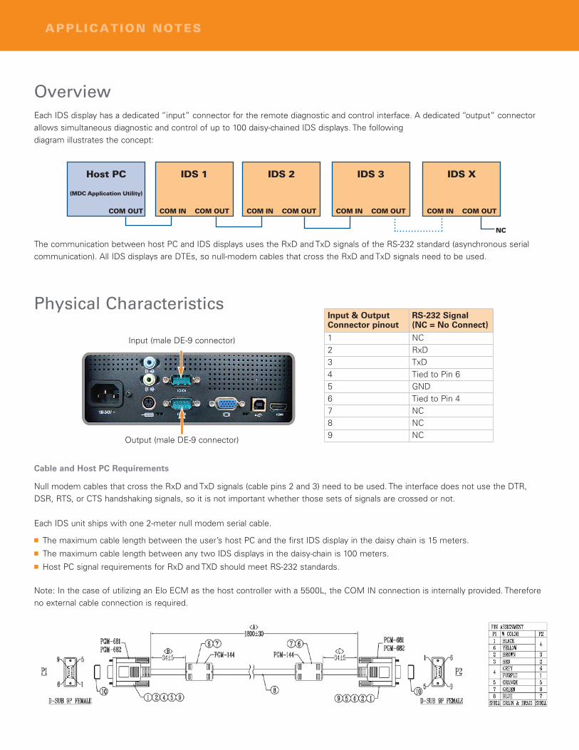
OverviewEach IDS display has a dedicated “input” connector for the remote diagnostic and control interface. A dedicated “output” connectorallows simultaneous diagnostic and control of up to 100 daisy-chained IDS displays. The following diagram illustrates the concept:
The communication between host PC and IDS displays uses the RxD and TxD signals of the RS-232 standard (asynchronous serialcommunication). All IDS displays are DTEs, so null-modem cables that cross the RxD and TxD signals need to be used.
APPLICATION NOTES
Physical Characteristics
Input (male DE-9 connector)
Output (male DE-9 connector)
Cable and Host PC Requirements
Null modem cables that cross the RxD and TxD signals (cable pins 2 and 3) need to be used. The interface does not use the DTR,DSR, RTS, or CTS handshaking signals, so it is not important whether those sets of signals are crossed or not.
Each IDS unit ships with one 2-meter null modem serial cable.
� The maximum cable length between the user’s host PC and the first IDS display in the daisy chain is 15 meters.� The maximum cable length between any two IDS displays in the daisy-chain is 100 meters.� Host PC signal requirements for RxD and TXD should meet RS-232 standards.
Note: In the case of utilizing an Elo ECM as the host controller with a 5500L, the COM IN connection is internally provided. Thereforeno external cable connection is required.
Input & OutputConnector pinout
RS-232 Signal(NC = No Connect)
1 NC2 RxD3 TxD4 Tied to Pin 65 GND6 Tied to Pin 47 NC8 NC9 NC
Command SetAll values are big-endian.
The required sequence of commands for this interface to be useful is:
First: Send a “Get Serial Numbers” (host PC queries the bus to find out how many IDS displays are connected; each connected display responds with its serial number)
Second: Send separate Get Command Set for each connected IDS display (host PC asks a specific IDS display for its supportedcommand set; the IDS display responds with its supported command set)
Third: host PC issues any command to one IDS display (host PC issues any supported command to one IDS display, the IDS display responds with a status
Format for Host PC Commands:
Format for IDS Display Response to a Host PC Read Command:
Format for IDS Display Response to a Host PC Write Command:
APPLICATION NOTES
Position/Order 1 2 3 4 5 6 7 8 9
Description Start Host address Length Target
AudienceCommand R/W Format
Command Type Write Value Checksum Stop
Position/Order 1 2 3 4 5 6 7 8 9
Description Start Host address Length Slave
AddressRequested R/W Format
Requested Type Return Data Checksum Stop
Position/Order 1 2 3 4 6 7 8 9
Description Start Host address Length Slave
Address Error Code RequestedCommand Checksum Stop
STARTValue: always 02h
HOST ADDRESSValue: always 6Eh
LENGTHValue: variable number that represents the number of bytesbetween LENGTH and CHECKSUM (non-inclusive). Range ofallowable values is between 80h and FFh. 80h means 0 bytes of length, FFh means 127 bytes of length.
TARGET AUDIENCEValue: Value depends on target.If the target is all connected IDS displays (for the GET SERIALNUMBERS command), the value is FFh.If the target is one specific IDS display (for all other commands),the value is 10 ASCII bytes representing that specific display’s 10-character serial number. For example, if the serial number ofthe target display is G10C987654, then the TARGET AUDIENCEwould be: 47h 31h 30h 43h 39h 38h 37h 36h 35h 34h
SLAVE ADDRESSValue: Depends on the host PC command.If the host PC command was GET SERIAL NUMBERS, the valueis 00hIf the host PC command was any other command, the value is 10 ASCII-coded hex bytes representing that specific display’s 10-character serial number.
COMMAND R/W FORMATValue: Depends if the COMMAND will be a Read or a Write.If the COMMAND is a Read, then the value is 01hIf the COMMAND is a Write, then the value is 04hSee the COMMAND section for details
STOPValue: always 03h
CHECKSUMValue: One byte truncated hexadecimal sum of bytes 2 through 7.
ERROR CODEValue: 04h – No Error
01h – COMMAND TYPE not supported by slave00h, 02h, 03h or 05h – Error
Command TypeValue: select from the following options:
The following provides an example transaction between the host PC and IDS display.
Host PC Command:Get Serial Numbers: 02 6E 83 FF 01 E2 D3 03
Function (for Writes) WRITE VALUE values and formats(only for write commands)
RETURN DATA values and formats(only for read commands)
Recall defaults 04h W only Restores brightness, contrast, volume, andAnalog VGA video timing parameters to factorydefaults
2 Byte setting: always 00h 01h 00h 00h: Recall function not active – noaction taken00h 01h: All settings recalled
ChangeBrightness
10h R or W For Read commands: slave will return its cur-rent brightness setting in RETURN DATA
For Write commands: slave will set its bright-ness setting according to the WRITE VALUE
2 Byte setting: 00h 00h (minimum; corresponds toOSD setting of 0)00h 64h (maximum; corresponds toOSD setting of 100)
Returns 4 bytes:2 bytes for max adjustable value (shouldbe 00h 64h)Followed by2 bytes for current value (should be inthe 00h 00h to 00h 64h range)
ChangeContrast
12h R or W For Read commands: slave will return its cur-rent contrast setting in RETURN DATA
For Write commands: slave will set its contrastsetting according to the WRITE VALUE
2 Byte setting:00h 00h (minimum; corresponds toOSD setting of 0)00h 64h (maximum; corresponds toOSD setting of 100)
Returns 4 bytes:2 bytes for max adjustable value (shouldbe 00h 64h)Followed by2 bytes for current value (should be inthe 00h 00h to 00h 64h range)
Perform Auto-Adjust
1Eh R or W Automatically adjusts input Analog VGA videofor optimum display on the display.
NOTE: IDS displays with Elo IDS ComputerModules use digital HDMI video
2 Byte setting:Always 00h 01h
00h 00h: auto-adjust not active – noaction taken00h 01h: Auto-adjust performed
Change AudioVolume
62h R or W For Read commands: slave will return its cur-rent volume setting in RETURN DATA
For Write commands: slave will set its volumesetting according to the WRITE VALUE
2 Byte setting:00h 00h (minimum; corresponds toOSD setting of 0)00h 64h (maximum; corresponds toOSD setting of 100)
Returns 4 bytes:2 bytes for max adjustable value (shouldbe 00h 64h)Followed by2 bytes for current value (should be inthe 00h 00h to 00h 64h range)
Get LifetimeInformation
C0h R only Requests the slave to report two values:1. How many accumulated hours the displayhas been connected to AC power (includesSLEEP and OFF time)2. How many accumulated hours the display’sbacklight has been on.
N/A – this field does not exist for thiscommand
Returns 4 bytes:2 bytes for accumulated display powerhours (high byte first, maximum of FFhFFH 65025 hrs)Followed by2 bytes for backlight on hours (high bytefirst, maximum of FFh FFH 65025 hrs)
Control TouchFunctionality
C7h R or W For Read commands: slave will return whetheror not touch functionality is turned on
For Write commands: slave will turn touchfunctionality on or off according to the WRITEVALUE
00h 00h (turn touch off)00h 01h (turn touch on)
00h 00h: touch function is off00h 01h: touch function is on
ControlDisplay Power
D6h R or W For Read commands: slave will return whetheror not the IDS display is turned on.
For Write commands: slave will power the dis-play on or off according to the WRITE VALUE
NOTE: This function will not work if the hostPC is an Elo IDS Computer ModuleNOTE: The display can be an IDS display byitself or an IDS display with integratedComputer Module.
E2h R All IDS displays connected to the bus reporttheir serial number. This allows Host PC soft-ware to address unique IDS displays.
N/A – this field does not exist for thiscommand
10 ASCII-coded hex bytes representingthat specific display’s 10-character serialnumber
Get CommandSet
F3h R Addressable (by serial number) to only oneconnected display at a time. The slave reportsthe list of commands that its hardware sup-ports.This command is useful for GUI development,to grey out features that may not be supportedby hardware.
N/A – this field does not exist for thiscommand
A list of COMMAND TYPES supportedby the slave, excluding the “GetCommand Set” command (which isalways assumed to be supported).For example, if the slave display supportsGet Command Set, Get Serial Numbers,Control Display Power, and Control TouchFunctionality, then this field would return3 bytes: E2h D6h C7h
APPLICATION NOTES
To find out more about our extensive range of Elo touch solutions, go to www.elotouch.com, or call the office nearest you.North AmericaElo Touch Solutions301 Constitution DriveMenlo Park, CA 94025-1110
Elo Touch Solutions, Inc. reserves the right to change or update, without notice, any information contained herein; to change, without notice, thedesign, construction, materials, processing or specifications of any products; and to discontinue or limit production or distribution of any products.
Elo (logo) and Elo Touch Solutions are trademarks of Elo Touch Solutions, Inc.
Copyright 2012 Elo Touch Solutions, Inc. All rights reserved. 10/12
ABOUT ELO TOUCH SOLUTIONS | Elo Touch Solutions, a portfolio company of The Gores Group, is a premier supplier of touch solutions including touchscreen components, touchmonitors, andall-in-one (AiO) touch computers for diverse applications including retail point-of-sale (POS), hospitality, kiosk, medical, industrial, and consumer devices. A pioneer in the industry with over 40 yearsof experience, we bring quality, innovation, and integrity to everything we touch. Visit www.elotouch.com or call 1-800-557-1458 for more information about Elo, its products and services.
The Elo Touch Solutions IDS displays are a stable hardware platform designed to withstand the rigors of high-use and public environ-ments while continuously delivering a sensitive and fluid touch response over time:
� Made for public use with rugged commercial components� Durable and reliable solutions for business� Integrated solutions
− Optional computer modules− Seamless integration; no cables − Enterprise-grade features
Contact the technical support center nearest you for more information on Elo IDS displays: