130
EMC ® Xtrem Family XtremSF ™ V 1.1 User Guide for VMware ® Systems P/N 302-000-274 REV 02

EMC® Xtrem FamilyXtremSF™
V 1.1
User Guide for VMware® SystemsP/N 302-000-274REV 02
EMC XtremSF • User Guide for VMware2
Copyright ©2013 EMC Corporation. All rights reserved. Published in the USA.
Published October, 2013
EMC believes the information in this publication is accurate as of its publication date. The information is subject to change without notice.
The information in this publication is provided as is. EMC Corporation makes no representations or warranties of any kind with respect to the information in this publication, and specifically disclaims implied warranties of merchantability or fitness for a particular purpose. Use, copying, and distribution of any EMC software described in this publication requires an applicable software license.
EMC2, EMC, and the EMC logo are registered trademarks or trademarks of EMC Corporation in the United States and other countries. All other trademarks used herein are the property of their respective owners.
For the most up-to-date regulatory document for your product line, go to EMC Online Support (https://support.emc.com).

EMC XtremSF • User Guide for VMware 3
Contents
Preface
Part 1 General Information
Chapter 1 General
System requirements..................................................................... 14Host requirements ................................................................... 15Thermal requirements.............................................................. 16
System BIOS settings..................................................................... 17Fan speed settings................................................................... 18Processor settings ................................................................... 18
Tools required ............................................................................... 19 Device life expectancy ................................................................... 19
Part 2 XtremSF550 and XtremSF2200
Chapter 2 XtremSF550\2200 Installation
Hardware installation .................................................................... 23 Installing the XtremSF driver .......................................................... 28
Installing the driver VIBs using the offline bundle .................... 29Installing the driver using VMware vSphere Update Manager ... 30
Upgrading the XtremSF drivers....................................................... 37 Upgrading controller firmware........................................................ 38 Removing the XtremSF drivers........................................................ 40
Chapter 3 XtremSF550\2200 Configuration
Defining a datastore on the XtremSF device ................................... 43 Using command line management utilities .................................... 48
esxcli vgc monitor.................................................................... 48vgc-secure-erase...................................................................... 49esxcli vgc config ...................................................................... 52vgc-diags ................................................................................. 54esxcli vgc beacon .................................................................... 55
Using devices in pass-through mode ............................................. 56
Chapter 4 Optimizing System Performance
Selecting acceleration mode.......................................................... 57 Configuring full performance for a single guest Windows VM.......... 58
4 EMC XtremSF • User Guide for VMware
Contents
Chapter 5 XtremSF550\2200 Troubleshooting
Device not detected on ESXi .......................................................... 63 Thermal throttling and shutdown ................................................... 64 Reduced IO performance due to Power Throttling ........................... 64 Firmware mismatch or device not initialized................................... 65 Device is degraded or is in read-only mode .................................... 65 Viewing system logs ...................................................................... 65 Empty vgc.diags.tar file.................................................................. 66
Part 3 XtremSF350, XtremSF700, XtremSF1400, XtremSF350S, and XtremSF700S
Chapter 6 XtremSF350\700\1400\350S\700S Installation
Hardware installation .................................................................... 69 Enabling use of disks for Direct Attached Storage .......................... 72 Installing the drivers ...................................................................... 73
Installing drivers for ESX 4.x\ESXi 4.x....................................... 73Installing drivers for ESX 5.0\5.1.............................................. 74Verifying proper installation..................................................... 75Installing the driver using VMware vSphere Update Manager ... 76Installing the management CLI................................................. 85
Removing the device driver from the ESX host................................ 85
Chapter 7 XtremSF350S\700S\350\700\1400 Configuration
RSSDM CLI..................................................................................... 87About the RSSDM CLI ............................................................... 88Managing a device using the RSSDM CLI.................................. 91Displaying device information using the RSSDM CLI............... 100
Chapter 8 XtremSF350S\700S\350\700\1400 Troubleshooting
Unplanned shutdown .................................................................. 109 Thermal shutdown....................................................................... 109
Part 4 XtremSF300S
Chapter 9 XtremSF300S Installation
Hardware installation .................................................................. 113 Enabling use of disks for Direct Attach Storage ............................ 116

EMC XtremSF • User Guide for VMware 5
Contents
Installing the XtremSF300S device driver ..................................... 117Installing drivers for ESX 4.1/ESXi 4.1.................................... 117Installing drivers for ESX 5.0\5.1............................................ 118
Removing the XtremSF300S driver from the ESX host ................... 118
Appendix A On-Board Diagnostic LEDs
XtremSF550\2200 ....................................................................... 122 XtremSF350\700\1400 ............................................................... 123 XtremSF350S\700S..................................................................... 125 XtremSF300S............................................................................... 126
Appendix B Identifying the PCIe Address of an XtremSF Device
Identifying the PCIe Address of an XtremSF350S\700S\350\700\1400 Device .......................................................................................... 127
Appendix C Upgrading an XtremSF Device

6 EMC XtremSF • User Guide for VMware
Contents

EMC XtremSF • User Guide for VMware 7
Preface
PREFACE
As part of an effort to improve its product lines, EMC periodically releases revisions of its software and hardware. Therefore, some functions described in this document might not be supported by all versions of the software or hardware currently in use. The product release notes provide the most up-to-date information on product features.
Contact your EMC technical support professional if a product does not function properly or does not function as described in this document.
Note: This document was accurate at publication time. Go to EMC Online Support (https://support.emc.com) to ensure that you are using the latest version of this document.
PurposeThis document describes how to install and configure XtremSF on VMware hosts.
AudienceThis document is intended for the host system administrator, system programmer, storage administrators, or operators who will be involved in installing and managing XtremSF.
Related documentationThe following EMC publications provide additional information:
◆ XtremSF Release Notes
◆ XtremSF Quick Start
◆ XtremSF User Guide for Linux Systems
◆ XtremSF User Guide for Windows Systems

8 EMC XtremSF • User Guide for VMware
Preface
Conventions used in this documentEMC uses the following conventions for special notices:
WARNING indicates a hazardous situation which, if not avoided, could result in death or serious injury.
CAUTION, used with the safety alert symbol, indicates a hazardous situation which, if not avoided, could result in minor or moderate injury.
NOTICE is used to address practices not related to personal injury.
Note: A note presents information that is important, but not hazard-related.
IMPORTANT
An important notice contains information essential to software or hardware operation.
Typographical conventions
EMC uses the following type style conventions in this document:
Bold Used for names of interface elements, such as names of windows, dialog boxes, buttons, fields, tab names, key names, and menu paths (what the user specifically selects or clicks)
Italic Used for full titles of publications referenced in text
Monospace Used for:• System output, such as an error message or script• System code• Pathnames, filenames, prompts, and syntax• Commands and options
Monospace italic Used for variables.
Monospace bold Used for user input.
[ ] Square brackets enclose optional values

EMC XtremSF • User Guide for VMware 9
Preface
Where to get helpEMC support, product, and licensing information can be obtained as follows:
Product information — For documentation, release notes, software updates, or information about EMC products, go to EMC Online Support at:
https://support.emc.com
Technical support — Go to EMC Online Support and click Service Center. You will see several options for contacting EMC Technical Support. Note that to open a service request, you must have a valid support agreement. Contact your EMC sales representative for details about obtaining a valid support agreement or with questions about your account.
Your commentsYour suggestions will help us continue to improve the accuracy, organization, and overall quality of the user publications. Send your opinions of this document to:
| Vertical bar indicates alternate selections — the bar means “or”
{ } Braces enclose content that the user must specify, such as x or y or z
... Ellipses indicate nonessential information omitted from the example

10 EMC XtremSF • User Guide for VMware
Preface

PART 1
General Information
Part 1 of this document describes general information about XtremSF devices, and the system requirements for the host machines in which the devices are installed.


13
General
CHAPTER 1General
EMC® XtremSF™ is a direct attach storage solution that reduces latency and increases throughput to dramatically improve application performance by leveraging PCIe Flash technology. XtremSF accelerates reads and writes by using very fast NAND storage media and because it resides on the PCIe bus within the server, very close to the CPU. The result is a local flash storage option for networked infrastructure that is dynamically optimized for performance, intelligence, and protection for both physical and virtual environments.
This document describes how to install, configure and manage EMC XtremSF solid state storage devices on VMware®–based systems.
The following table lists the devices that are described in this document.
Table 1 XtremSF devices
Device Name Model NumberCard Part Number
EMC HW Kit Number NAND
Data Write Endurance
XtremSF350 PCIEHHM-350M 118033270 100-563-877-00 eMLC 5.25 PB
XtremSF550 PCIEHHM-550V 118033009 100-564-161-00 eMLC 10 PB
XtremSF700 PCIEHHM-700M 118033217 100-564-766-00 eMLC 10.5 PB
XtremSF1400 PCIEHHM-1400M 118033218 100-564-767-00 eMLC 21 PB
XtremSF2200 PCIEHHM-2200V118033003 100-564-163-00
cMLC 33 PB118000377 100-563-899-00
XtremSF300S PCIEHHS-3XXL 118032854 100-564-120 SLC 36.6 PB
XtremSF350S PCIEHHS-3XXM2 118032997 100-564-162-00 SLC 52.5 PB
XtremSF700S PCIEHHS-7XXM 118032843 100-564-160-00 SLC 105 PB

14 EMC XtremSF • User Guide for VMware
General
Note: The XtremSF350S and XtremSF700S devices mentioned in Table 1 are intended for use with EMC XtremSW Cache™ software, or can be used in a Direct Attached Storage (DAS) solution. These devices do not include a power holdup circuit, and in case of sudden power loss, some data may not be written to the flash device. When used as DAS devices for mission-critical data, EMC recommends that these devices be used in computer systems with a battery backup solution in place. For non-mission-critical data, use battery backup solutions at your discretion, according to your particular use case.
This chapter describes general information and information about system and thermal requirements for XtremSF devices. Topics include:
◆ System requirements ....................................................................................... 14◆ System BIOS settings ....................................................................................... 17◆ Tools required .................................................................................................. 19◆ Device life expectancy...................................................................................... 19
System requirementsThis section describes the host and thermal requirements for XtremSF devices.

System requirements 15
General
Host requirements
Your host machine must meet the requirements listed in Table 2, “Host machine requirements for XtremSF350\550\700\1400\2200,”or Table 3, “Host machine requirements for Xtrem300S\SF350S\700S,”depending on your XtremSF model.
Note: XtremSF devices must be installed in x8 or x16 PCIe slots. Some systems have PCIe slots with x8 physical connectors that only provide x4 electrical connectivity. From a performance point of view, these slots behave like an x4 slot, which would reduce device performance, and is therefore not recommended for use. Check your system documentation for PCIe slot specifications.
Table 2 Host machine requirements for XtremSF350\550\700\1400\2200
Requirement Details
PCI-Express slot Gen 2, x8\x16 electrical slot, half-height and half-length
Minimum airflow • XtremSF550—150 Linear Feet per Minute (LFM) airflow over the device, with card inlet at 45° C
• XtremSF2200—200 LFM airflow over the device, with card inlet at 45° C
• XtremSF350—300 Linear Feet per Minute (LFM) airflow over the device, with card inlet at 50° C
• XtremSF700—300 Linear Feet per Minute (LFM) airflow over the device, with card inlet at 50° C
• XtremSF1400—300 Linear Feet per Minute (LFM) airflow over the device, with card inlet at 50° C
Processor Multicore Intel Xeon® (5500-series or later) or AMD Opteron™
Minimum memory • XtremSF350—Not applicable• XtremSF550—2 GB of memory• XtremSF700—Not applicable• XtremSF1400—Not applicable• XtremSF2200—6 GB of memory
Operating system • VMware vSphere® 5.0 or VMware vSphere 5.1• XtremeSF350\700\1400 devices support the
out-of-box VMware vSphere 5.5 driver
Administrative Privileges Root / Administrator privileges are required for CLI commands

16 EMC XtremSF • User Guide for VMware
General
Thermal requirements
This section describes thermal requirements for XtremSF devices. These requirements ensure optimal operating conditions for XtremSF devices.
Table 3 Host machine requirements for Xtrem300S\SF350S\700S
Requirement Details
PCI-Express slot Gen 2, x8\x16 electrical slot, half-height and half-length
Minimum airflow 300 Linear Feet per Minute (LFM) airflow over the device, with card inlet at 50° C
Processor Multicore Intel Xeon® (5500-series or later) or AMD Opteron™
Minimum memory 8 GB (12 GB recommended).
Operating system • VMware ESX 4.0, ESX 4.1, ESXi 4.1, ESX 5.0 and ESX 5.1.
Note: If you intend to install XtremSW Cache on your device, refer to the XtremSW Cache Installation Guide for further system requirements.
Administrative Privileges Root / Administrator privileges are required for CLI commands
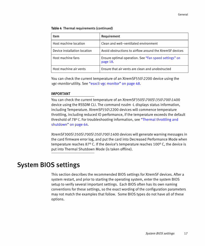
Table 4 Thermal requirements
Item Requirement
Ambient temperature range • XtremSF550\2200: 0o C–45o C
• XtremSF300S\350S\700S\350\700\1400: 0o C–50o C
Maximum device operating temperature
• XtremSF550\2200: less than 83o C• XtremSF300S\350S\700S\350\700\1400: less than
100o C
BIOS settings Set to optimal airflow and cooling settings. See “Fan speed settings” on page 18.
Minimum airflow See Table 2 on page 15.
System BIOS settings 17
General
You can check the current temperature of an XtremSF550\2200 device using the vgc-monitor utility. See “esxcli vgc monitor” on page 48.
IMPORTANT
You can check the current temperature of an XtremSF350S\700S\350\700\1400 device using the RSSDM CLI. The command rssdm -L displays status information, including Temperature. XtremSF550\2200 devices will commence temperature throttling, including reduced IO performance, if the temperature exceeds the default threshold of 78o C. For troubleshooting information, see “Thermal throttling and shutdown” on page 64.
XtremSF300S\350S\700S\350\700\1400 devices will generate warning messages in the card firmware error log, and put the card into Decreased Performance Mode when temperature reaches 87o C. If the device’s temperature reaches 100o C, the device is put into Thermal Shutdown Mode (is taken offline).
System BIOS settingsThis section describes the recommended BIOS settings for XtremSF devices. After a system restart, and prior to starting the operating system, enter the system BIOS setup to verify several important settings. Each BIOS often has its own naming conventions for these settings, so the exact wording of the configuration parameters may not match the examples that follow. Some BIOS types do not have all of these options.
Host machine location Clean and well–ventilated environment
Device installation location Avoid obstructions to airflow around the XtremSF devices
Host machine fans Ensure optimal operation. See “Fan speed settings” on page 18.
Host machine air vents Ensure that air vents are clean and unobstructed
Table 4 Thermal requirements (continued)
Item Requirement

18 EMC XtremSF • User Guide for VMware
General
Fan speed settings
This section describes how to configure fan speed settings in your system’s BIOS. Good airflow is an important factor in maintaining optimal operating conditions.
If your system has BIOS settings for configuring system fan speeds, select options that maximize the airflow. Refer to your host machine vendor’s documentation for detailed configuration instructions.
The following examples show how to modify fan speeds on some HP and Dell systems:
To configure fan speeds on some HP systems, perform the following:
Select BIOS > Advanced Options > Thermal Configuration > Increased/Maximum Cooling.
To configure fan speeds on some Dell systems, perform the following:
Select System Settings > iDRAC Settings > Thermal, and enable the following options
• Maximum Performance
• Fan Speed Offset
• High Fan Speed Offset
Processor settings
This section describes the processor settings that should be configured in your system’s BIOS. The following settings are often found in the Advanced Processor/Chipset Control BIOS menus.
Disable the following optional settings:
• Processor Performance States / C States / C-State Tech / EIST
• C1E States / C1 Enhanced States
• (Link) Active State Power Management
On Intel™ based systems, enable the following:
• Hyperthreading / Logical Processors
• Turbo Mode

Tools required 19
General
If there are performance profiles (System Power Modes) available, set them to Maximum Performance.
Intel has identified an issue in Xeon E5-2600 series processors that may result in severe drops of PCIe and XtremSF bandwidth when running workloads that have low CPU consumption. To avoid this issue, disable C2 and C1E processor power states. For details, see Erratum BT160 in the following document:http://www.intel.com/content/dam/www/public/us/en/documents/specification-updates/xeon-e5-family-spec-update.pdf
Tools requiredA standard screwdriver set may be necessary for XtremSF device installation, depending on your specific server. Check your system’s documentation for details.
Device life expectancyThe expected maximum endurance of an XtremSF device is:
◆ XtremSF350—5.25 PB data written to flash
◆ XtremSF550—10 PB data written to flash
◆ XtremSF700—10.5 PB data written to flash
◆ XtremSF1400—21 PB data written to flash
◆ XtremSF2200—33 PB data written to flash
◆ XtremSF300S—36.6 PB data written to flash
◆ XtremSF350S—52.5 PB data written to flash
◆ XtremSF700S—105 PB data written to flash
Note: The vgc-monitor utility displays the remaining lifetime of XtremSF550\2200 devices, expressed in percentage format. For more information, see “esxcli vgc monitor” on page 48.
When XtremSF300S\350S\700S\350\700\1400 devices near the end of their lifetime, they generate messages to the card firmware error log.

20 EMC XtremSF • User Guide for VMware
General

PART 2
XtremSF550 and XtremSF2200
Part 2 of this document describes the following devices:
◆ XtremSF550 (PCIEHHM-550V)
◆ XtremSF2200 (PCIEHHM-2200V)
Chapters include:
Chapter 2, “XtremSF550\2200 Installation,”on page 23
This chapter explains how to install a device in the server, and how to install drivers. It also contains uninstall procedures and upgrade procedures.
Chapter 3, “XtremSF550\2200 Configuration,”on page 43
This chapter explains how to configure and manage devices.
Chapter 4, “Optimizing System Performance,”on page 57
This chapter explains how to optimize system performance with your device.
Chapter 5, “XtremSF550\2200 Troubleshooting,”on page 63
This chapter explains how to troubleshoot problems with your device.


Hardware installation 23
XtremSF550\2200 Installation
CHAPTER 2XtremSF550\2200 Installation
This chapter describes how to install XtremSF550\2200 hardware and software, and how to perform initial configuration activities. It also explains how to upgrade firmware, when necessary. Topics include:
◆ Hardware installation ....................................................................................... 23◆ Installing the XtremSF driver............................................................................. 28◆ Upgrading the XtremSF drivers ......................................................................... 37◆ Upgrading controller firmware .......................................................................... 38◆ Removing the XtremSF drivers .......................................................................... 40
Hardware installationThis section describes how to install an XtremSF550\2200 storage device in a host machine. Read the procedures and observe all special notices before you start installing the device.
To avoid electrical shock, disconnect the computer from the main power supply and from any networks before installing the XtremSF device.
Observe Electrostatic Discharge (ESD) precautions while installing or handling XtremSF devices. ESD can damage host machine and/or device components.
IMPORTANT
Before changing your system configuration, ensure that you backup your data. Before saving data on the XtremSF device, ensure that you perform all configuration activities and partitioning. For more information, see “XtremSF550\2200 Configuration” on page 43.

24 EMC XtremSF • User Guide for VMware
XtremSF550\2200 Installation
IMPORTANT
Before you install the XtremSF device, it is highly recommended that you record the following information, found on the label that is affixed to the device:
◆ Serial number (FNM): ____________________________________
◆ EMC Hardware Kit number : 100– 56x___________________________
◆ Revision number (REV) : ____________________________________
Recording this information before installing the device into your system can ease future troubleshooting operations.
Use only the EMC-supplied brackets. Do not remove the heatsinks during the bracket replacement process. Doing so may cause damage to the device and void the warranty.
To install the device, perform the following steps:
1. Unpack the device and inspect it for damage. Unpack the device in a static-free environment and follow good antistatic grounding procedures. Remove the device from the antistatic bag and carefully inspect the device for damage. If you notice any damage, or if any component is missing, contact EMC customer support.
2. Prepare the computer. Turn off the computer, and disconnect the power cord from the power supply. Disconnect any network cabling. Remove the cover from the chassis.
3. Replace the mounting bracket (system dependent). If required for your system, replace the mounting bracket that ships on the device with the additional bracket supplied with the device. To replace the bracket, remove the mounting screws from the back of the device, install the new bracket, and re-tighten the screws evenly. Mounting screw locations for the device are shown in Figure 1 on page 25 and Figure 2 on page 26.
• For a device with retaining nuts as shown in Figure 1 on page 25, use an m 2.5 screw driver and an m 2.5 nut driver.
• For a device without retaining nuts, remove only the two screws nearest the bracket as shown in Figure 2 on page 26. Use an m 2.5 screw driver.

Hardware installation 25
XtremSF550\2200 Installation
Slide the bracket in horizontally to line up with the screw holes. Tighten the screws.
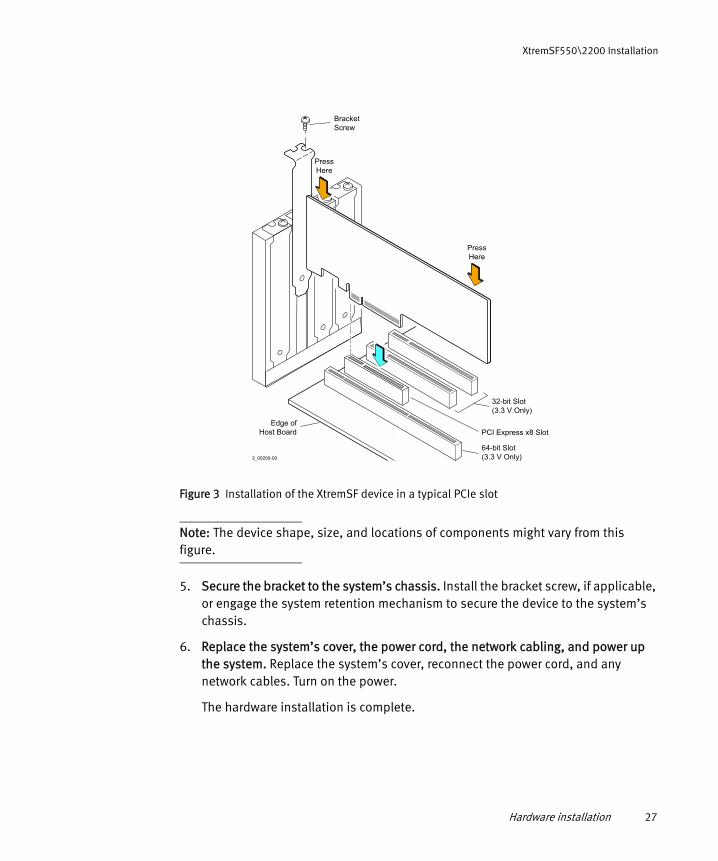
4. Insert the XtremSF device in an available PCI Express slot. Locate an empty PCI Express slot. Remove the blank bracket panel on the computer chassis that aligns with the empty PCI Express slot. Save the bracket screw, if applicable.
Align the device to a PCI Express slot. Press down gently, but firmly, to properly seat the device in the slot. Figure 3 on page 27 shows how to insert the device in a PCI Express slot.
Figure 1 Bracket mounting nut locations on single-board model

26 EMC XtremSF • User Guide for VMware
XtremSF550\2200 Installation
Figure 2 Bracket mounting screw locations on double-board model
Hardware installation 27
XtremSF550\2200 Installation
Figure 3 Installation of the XtremSF device in a typical PCIe slot
Note: The device shape, size, and locations of components might vary from this figure.
5. Secure the bracket to the system’s chassis. Install the bracket screw, if applicable, or engage the system retention mechanism to secure the device to the system’s chassis.
6. Replace the system’s cover, the power cord, the network cabling, and power up the system. Replace the system’s cover, reconnect the power cord, and any network cables. Turn on the power.
The hardware installation is complete.
3_00200-00
64-bit Slot(3.3 V Only)
32-bit Slot(3.3 V Only)
PressHere
PressHere
Bracket Screw
Edge ofHost Board PCI Express x8 Slot

28 EMC XtremSF • User Guide for VMware
XtremSF550\2200 Installation
Installing the XtremSF driverThis section describes how to install the XtremSF550\2200 driver. Topics include:
◆ “Installing the driver VIBs using the offline bundle” on page 29◆ “Installing the driver using VMware vSphere Update Manager” on page 30
Note: EMC strongly recommends that you upgrade your device’s firmware and drivers to the latest version available on the Support site.If you intend to use XtremSW Cache 2.0 or higher with your device, you must upgrade your device to v1.1 or higher (firmware and drivers).
Use the following methods to run the ESXCLI commands mentioned in this section:
◆ Directly on the ESXi host after logging in via SSH (SSH service must be enabled)
Syntax:
esxcli <command name space> <command arguments>
Example:
esxcli software vib list
◆ Remotely, using the vSphere Remote CLI utility (VCLI), which can be downloaded from http://www.vmware.com/support/developer/vcli/
Note: Ensure that you download the correct VCLI utility for your version of ESX.If any VCLI command contains a filename, the file should be present on the target system, and not on the system where VCLI is executed.
Syntax:
esxcli --server=<ESX host name/IP Address> --username=<root> --password=<password> <command name space> <command arguments>
Example:
esxcli --server=lab-m6 --username=root -password=password software vib list

Installing the XtremSF driver 29
XtremSF550\2200 Installation
Installing the driver VIBs using the offline bundle
The offline bundle is supplied with your XtremSF550\2200 device’s installation media in the directory for your operating system and device model. The name of the required file is: EMCvPCIeSSD-ESX5x-1.0.SP4.GA.60554.60740.C7A.x86_64.zip
Note: You must restart the host machine after installing the driver.
To install the driver VIBs using the offline bundle, follow these steps:
1. Save the .zip file in the tmp directory on your ESX host.
2. Type the following command, making sure that you provide the full path to the bundle file:
esxcli software vib install -d <full_path_to_bundle_file>
A message similar to the following sample output is displayed:
Installation ResultMessage: The update completed successfully, but the system needs to be rebooted for the changes to be effective.Reboot Required: trueVIBs Installed: EMC_bootbank_block-vgc_1.0.GA.60740.C7A-1OEM.500.0.0.472560, EMC_bootbank_esxcli-vgc-utils_1.0.GA.60740.C7A-5.0.0.464360 VIBs Removed: VIBs Skipped:
3. Restart the host machine.
4. Check whether the installation was successful by typing the following command:
esxcli software vib list | grep -i emc
A message similar to the following sample is displayed if installation was successful:
block-vgc 1.0.SP4.GA.60740.C7A-1OEM.500.0.0.472560 EMC VMwareCertified 2013-08-08
esxcli-vgc-utils 1.0.SP4.GA.60740.C7A-5.0.0.464360 EMC PartnerSupported 2013-08-08

30 EMC XtremSF • User Guide for VMware
XtremSF550\2200 Installation
5. Verify that the device is recognized correctly by typing the command:
esxcli vgc monitor drive
A message similar to the following sample output is displayed:
Driver Uptime: 16:16Card Name Num Partitions Card Type Statusvgca 1 PCIEHHM-550V Good
Partition Usable Capacity RAID vgca0 555 GB enabled
Card Name Num Partitions Card Type Statusvgcb 1 PCIEHHM-550V Good
Partition Usable Capacity RAID vgcb0 555 GB enabled
~ #
Installation is complete.
6. Create a datastore and perform other configuration procedures, as described in “XtremSF550\2200 Configuration” on page 43.
Installing the driver using VMware vSphere Update Manager
This section describes how to install the device driver bundle using vSphere Update Manager (VUM). The XtremSF550\2200 device driver bundle is supplied on your device’s installation media, in the directory for your operating system and device model.
Note: You must restart the host machine after installing the driver.
To install the driver using VUM, follow these steps:
1. In the vSphere Client’s Update Manager Administration window, click the Patch Repository tab.
2. Click Import Patches. The Import Patches window is displayed.

Installing the XtremSF driver 31
XtremSF550\2200 Installation
a. Type the path and filename of the vPCIe device driver bundle (in ZIP file format) in the Patches.zip file box, or click Browse to navigate to the file.
b. Click Next. The upload process begins, and may last for several minutes. Do not close the window until the upload is complete.
c. Click Finish to confirm the import.
32 EMC XtremSF • User Guide for VMware
XtremSF550\2200 Installation
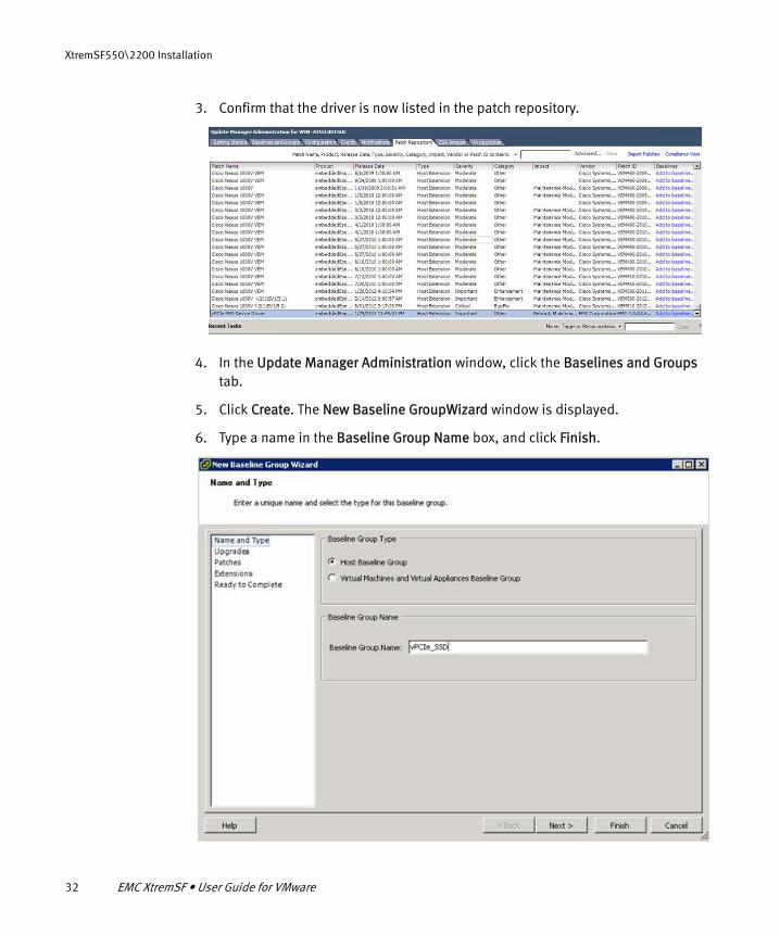
3. Confirm that the driver is now listed in the patch repository.
4. In the Update Manager Administration window, click the Baselines and Groups tab.
5. Click Create. The New Baseline GroupWizard window is displayed.
6. Type a name in the Baseline Group Name box, and click Finish.

Installing the XtremSF driver 33
XtremSF550\2200 Installation
7. Create a new baseline name with the Type Host Extension.
8. Add a new baseline with the baseline group that you just created.
9. Select the ESX server in the left pane of the main window. Click the Update Manager tab and click Attach. A new window is displayed.

34 EMC XtremSF • User Guide for VMware
XtremSF550\2200 Installation
• Select the baseline and baseline group that you created earlier, and click Attach.
10. In the vSphere Client main window, click Stage.

Installing the XtremSF driver 35
XtremSF550\2200 Installation
11. When staging is complete, click Remediate. The Remediate window is displayed.
• Ensure that the baseline that you created is selected, click Next twice, and then click Finish.
12. Click Remediate again. The Remediate window is displayed.

36 EMC XtremSF • User Guide for VMware
XtremSF550\2200 Installation
a. In the left pane, click Patches and Extensions, select the vPCIe SSD patch, and click Next.
b. Type a task name and a task description in the corresponding boxes, and select the time that you want to perform the remediation. Click Next.

Upgrading the XtremSF drivers 37
XtremSF550\2200 Installation
c. Click Finish. The remediation will be performed at the time that you specified. The driver installation is complete.
13. Create a datastore and perform other configuration procedures, as described in “XtremSF550\2200 Configuration” on page 43.
For additional vSphere Update Manager details, refer to your VMware documentation.
Upgrading the XtremSF driversThis section describes how to upgrade drivers for an XtremSF550\2200 device.
To update the drivers, perform the following steps:
1. Ensure that all applications using the XtremSF550\2200 devices are stopped.
2. Copy the driver file from the installation media directory for your operating system and device model, to a directory on your host machine.
3. Type the command
esxcli software vib update –d <full_path_to_driver>
where <full_path_to_driver> is the full path to the driver file that you copied in Step 2.
4. Follow the on-screen instructions, and restart the host machine when instructed to do so.
38 EMC XtremSF • User Guide for VMware
XtremSF550\2200 Installation
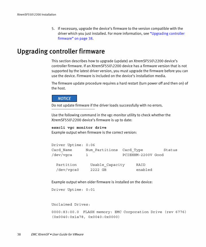
5. If necessary, upgrade the device’s firmware to the version compatible with the driver which you just installed. For more information, see “Upgrading controller firmware” on page 38.
Upgrading controller firmwareThis section describes how to upgrade (update) an XtremSF550\2200 device’s controller firmware. If an XtremSF550\2200 device has a firmware version that is not supported by the latest driver version, you must upgrade the firmware before you can use the device. Firmware is included on the device’s installation media.
The firmware update procedure requires a hard restart (turn power off and then on) of the host.
Do not update firmware if the driver loads successfully with no errors.
Use the following command in the vgc-monitor utility to check whether the XtremSF550\2200 device’s firmware is up to date:
esxcli vgc monitor driveExample output when firmware is the correct version:
Driver Uptime: 0:06Card_Name Num_Partitions Card_Type Status/dev/vgca 1 PCIEHHM-2200V Good
Partition Usable_Capacity RAID /dev/vgca0 2222 GB enabled
Example output when older firmware is installed on the device:
Driver Uptime: 0:01
Unclaimed Drives:
0000:83:00.0 FLASH memory: EMC Corporation Drive (rev 6776) (0x0040:0x1a78, 0x0040:0x0000)

Upgrading controller firmware 39
XtremSF550\2200 Installation
Unclaimed Drives:
0000:84:00.0 FLASH memory: EMC Corporation Drive (rev 6776) (0x0040:0x1a78, 0x0040:0x0000)
If firmware upgrade is required, perform the following steps:
Do not disconnect power during the update process.Do not interrupt the update process.
1. Ensure that all applications using the XtremSF550\2200 devices are stopped.
2. Type the following command: cd /opt/vgc/bin/
3. Type the following command: ./vgc-update.sh
Some warning messages are displayed.
4. Follow the on-screen instructions. The upgrade process begins, and status messages are displayed.
5. When the following message is displayed, shut down (power off) and then power up your system:
PLEASE POWER CYCLE SYSTEM NOW
Host system hard restart is mandatory for a successful firmware upgrade.
6. Verify that the driver is loaded correctly and that the device is recognized by typing the command:
esxcli vgc monitor drive
Output should be similar to the first example provided in this section.
The firmware upgrade is complete.

40 EMC XtremSF • User Guide for VMware
XtremSF550\2200 Installation
Removing the XtremSF driversThis section describes how to uninstall the XtremSF550\2200 drivers called block-vgc and esxcli-vgc-utils.
To uninstall drivers:
1. Check which driver files are installed on your ESXi host by typing the following command (optional):
esxcli software vib list | grep -i emc
Output similar to the following is displayed:
block-vgc 1.0.SP4.GA.60239M.C7A-1OEM.500.0.0.472560 EMC VMwareCertified 2013-08-08esxcli-vgc-utils 1.0.SP4.GA.60239M.C7A-5.0.0.464360 EMC PartnerSupported 2013-08-08
2. Remove block-vgc by typing the following command:
esxcli software vib remove -n block-vgc
Output similar to the following is displayed:
Removal Result Message: The update completed successfully, but the system needs to be rebooted for the changes to be effective. Reboot Required: true VIBs Installed: VIBs Removed: EMC_bootbank_block-vgc_1.0.SP4.GA.60239M.C7A-1OEM.500.0.0.472560 VIBs Skipped:~ #
3. Remove esxcli-vgc-utils by typing the following command:
esxcli software vib remove -n esxcli-vgc-utils
Output similar to the following is displayed:
Removal Result Message: The update completed successfully, but the system needs to be rebooted for the changes to be effective. Reboot Required: true VIBs Installed: VIBs Removed: EMC_bootbank_esxcli-vgc-utils_1.0.SP4.GA.60239M.C7A-5.0.0.464360 VIBs Skipped:

Removing the XtremSF drivers 41
XtremSF550\2200 Installation
~ #
4. Restart the ESXi host.
5. Repeat the first step in this procedure and verify that the drivers no longer appear in the output message.
Uninstallation is now complete.

42 EMC XtremSF • User Guide for VMware
XtremSF550\2200 Installation
Defining a datastore on the XtremSF device 43
XtremSF550\2200 Configuration
CHAPTER 3XtremSF550\2200 Configuration
This chapter describes how to configure your XtremSF550\2200 device. Topics include:
◆ Defining a datastore on the XtremSF device...................................................... 43◆ Using command line management utilities ....................................................... 48◆ Using devices in pass-through mode ................................................................ 56
Defining a datastore on the XtremSF deviceThis section describes how to define a datastore on the XtremSF550\2200 device. You must define a datastore before you start using the device.
To define a datastore, perform the following steps:
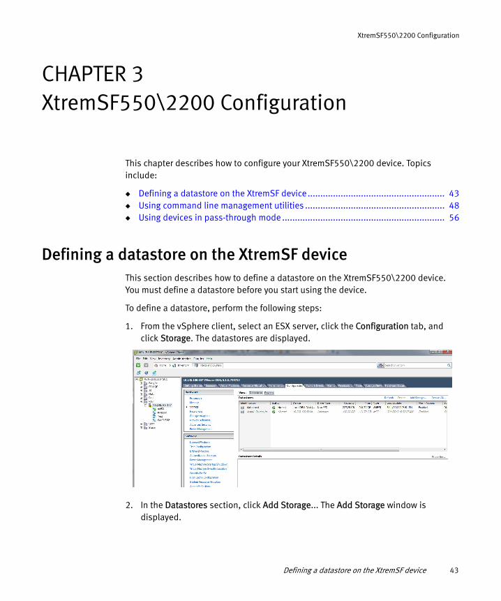
1. From the vSphere client, select an ESX server, click the Configuration tab, and click Storage. The datastores are displayed.
2. In the Datastores section, click Add Storage... The Add Storage window is displayed.
44 EMC XtremSF • User Guide for VMware
XtremSF550\2200 Configuration
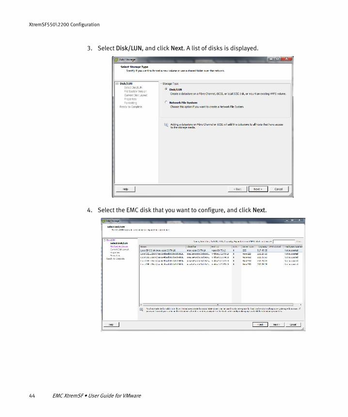
3. Select Disk/LUN, and click Next. A list of disks is displayed.
4. Select the EMC disk that you want to configure, and click Next.

Defining a datastore on the XtremSF device 45
XtremSF550\2200 Configuration
5. Select VMFS-5, and click Next. A summary of the current disk layout is displayed.
6. Click Next.

46 EMC XtremSF • User Guide for VMware
XtremSF550\2200 Configuration
7. Type a name for the new datastore, and click Next.
8. Select Maximum Available Space, and click Next. A summary of the disk layout is displayed.
Defining a datastore on the XtremSF device 47
XtremSF550\2200 Configuration
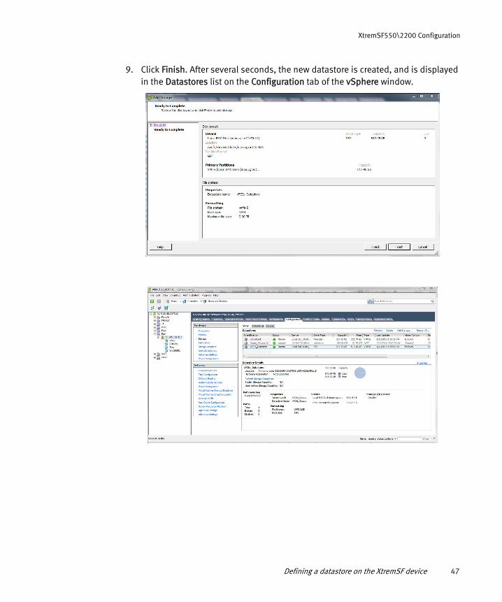
9. Click Finish. After several seconds, the new datastore is created, and is displayed in the Datastores list on the Configuration tab of the vSphere window.

48 EMC XtremSF • User Guide for VMware
XtremSF550\2200 Configuration
Using command line management utilitiesYou can use command line utilities to manage XtremSF550\2200 devices. The following table summarizes the uses of these utilities.
esxcli vgc monitor
You can use the esxcli vgc monitor utility to monitor XtremSF550\2200 device status, remaining life, and health. When called without parameters, it lists all XtremSF devices in the system with their configuration and health summary.
Command syntax:
esxcli vgc monitor drive
Table 5 CLI management utilities
To do this Use this utility See page
• Monitor device status and health• View device configurations
esxcli vgc monitor page 48
• Securely erase (“sanitize”) all data from a device
vgc-secure-erase page 49
• Configure write acceleration mode• Partition a device• List current device configuration• Reset to factory defaults
esxcli vgc config page 52
• Save support information into a single file. You can send this file to EMC Online Support
vgc-diags page 54
• Use the on-board LEDs to physically identify a device
esxcli vgc beacon page 55
Options Description
no args Display info for all drives (vgc[a-h] drives)
-d Drive name /dev/vgc[a-h]Display info for the given drive.
-h Display help and exit

Using command line management utilities 49
XtremSF550\2200 Configuration
Example of detailed sample output:
vgc-secure-erase
You can use the secure erase feature to ensure that all user data is securely erased (sanitized) from the flash media. You can use this feature if an XtremSF550\2200 device:
◆ needs to be returned for repair or replacement
◆ is being leveraged for a new project
◆ needs to be securely cleaned of data prior to leaving the facility, or prior to redeployment for another project
Driver Uptime: 10:29
Card_Name Num_Partitions Card_Type Status
vgca 1 PCIEHHM-550V Good
Serial Number : SJT00460
Card Info : Part: 118033009
Rev : vPCIe SSD 52879, x8 Gen2
Temperature : 48 C (Safe)
Temp Throttle : Inactive
Card State Details
: Normal
Action Required : None
Partition Usable_Capacity RAID
vgca0 555 GB enabled
Mode : maxcapacity
Total Flash Bytes : 123277825998848 (123.28TB) (reads)
200436422639616 (200.44TB) (writes)
Remaining Life : 98.22%
Partition State : READY
Flash Reserves Left
: 100%

50 EMC XtremSF • User Guide for VMware
XtremSF550\2200 Configuration
Sanitization standards are different, depending upon the type of media being used. For example, the standards required for magnetic disk media are different from the standards required for flash memory.
Data sanitization standards
There are different levels of sanitization: Clear and Purge. In most cases, Clear will suffice, but in some cases Purge is required. The secure erase utility supports both Clear and Purge.
The secure erase utility complies with the Clear and Purge levels of sanitization in accordance with the following Government standards:
◆ DOD 5220.22-M—Complies with sanitization requirements for Flash EPROM(http://www.dss.mil/documents/pressroom/isl_2007_01_oct_11_2007_final_agreement.pdf)
◆ NIST SP800-88—Complies with instructions for Flash EPROM(http://csrc.nist.gov/publications/nistpubs/800-88/NISTSP800-88_with-errata.pdf)
The specifications state the following requirements (quoted from NIST and DOD) for the two levels of sanitization:
◆ Clear: Perform a full chip erase as per manufacturer’s data sheets.
◆ Purge: Overwrite all addressable locations with a single character, followed by performing a full chip erase as per manufacturer’s data sheets.
Operation
The XtremSF device must be in a minimally operative state in when you use the secure erase utility. Ensure that the device is not in use before using this utility. The secure erase utility attempts to erase all user data from the partitions on the device using the selected method (Clear or Purge).
In the case of XtremSF550 devices, only one partition is present, and the operation is performed on the entire device. In the case of partitioned XtremSF2200 devices, the operation must be performed separately on each partition.
Clear or Purge may not be successful, because some blocks that contain user data are no longer accessible, due to media failure. In such cases, error messages are produced. There are some cases where a block is not usable from the start, and is marked bad when the device is shipped from the factory, and therefore never receives

Using command line management utilities 51
XtremSF550\2200 Configuration
any user data. These blocks cannot be 'sanitized', however since they are guaranteed never to receive user data, the utility can successfully sanitize a device when these blocks are present.
Note: vgc-secure-erase is not an esxcli command. It must be executed in the shell.
Command Syntax:
Example command for clearing device vgca0:
/opt/vgc/bin/vgc-secure-erase /dev/vgca0
A message similar to the following sample output is displayed:
This operation will erase all data on the physical partition vgca0. It will take up to 20 minutes to complete.
Once started you cannot stop or undo this operation.Do you want to continue? [yes/no]yesStarting Secure Erase (Clear) operation. Please wait ...Result:Secure Erase (Clear) on partition vgca0 completed successfully.
Operation Summary:
/opt/vgc/bin/vgc-secure-erase [-p|--purge] [-y|--yes] <partition>/opt/vgc/bin/vgc-secure-erase [-c|--clear] [-y|--yes] <partition>
vgc-secure-erase -h|--help
Options Description
-c | --clear Clears (Erases) the contents of the partition. This is the default option.
-p | --purge Purges (Erases and overwrites) the contents of the partition.
-y | --yes Starts the operation without user confirmation.
-h | --help Displays options/parameters that vgc-secure-erase can take.
partition Represents the partition instance [a-h][0-1] (for example: vgca0)

52 EMC XtremSF • User Guide for VMware
XtremSF550\2200 Configuration
Number of erase operations skipped due to factory bad blocks : 205Number of erase operations skipped due to grown bad blocks : 0Number of erase operation failures : 0Reformatting the partition /dev/vgca0#
esxcli vgc config
You can use the vgc config utility to perform the following configuration tasks:
◆ Switch between maxcapacity and maxperformance write acceleration modes
◆ Split a device into two physical partitions of equal size, and assign a different acceleration mode to each partition, if desired
Ensure that the XtremSF550\2200 device is not in use before using this utility.
Acceleration modes
By default, XtremSF550\2200 devices are formatted in maxcapacity mode. If your application is random or mixed write intensive, setting maxperformance mode instead of maxcapacity mode can be beneficial. Maxperformance mode provides twice as much sustained random write performance while reducing available user capacity of the device by 17%. Read performance and sequential write performance are the same in maxperformance and maxcapacity modes. Only workloads that generate a significant amount of random write I/O can benefit from using maxperformance mode.
Partitioning
Partitioning of the XtremSF2200 device into two separate physical partitions allows complete physical isolation of workloads and data on these partitions (XtremSF550 model supports only one physical partition). It is possible to configure two partitions on a device and assign different acceleration modes to each partition. The two physical partitions are presented as separate block devices, such as vgca0 and vgca1. However, in most cases EMC recommends using the default configuration with one physical partition, and using software partitions or LVM.
Changes made with vgc-config will erase existing data on the affected device or partition. Perform a backup before modifying existing settings.

Using command line management utilities 53
XtremSF550\2200 Configuration
Note: If you intend to install XtremSW Cache software v2.0.0 or earlier, do not partition the device.
Command Syntax:
The command in the following example configures the partition /dev/vgca0 in maxperformance mode:
esxcli vgc config partition -p /dev/vgca0 -m maxperformance
esxcli vgc config -h
esxcli vgc config list -d <drive name> | -p <partition name>
esxcli vgc config drive -d <drive name> -n <1/2> -m <maxperformance/maxcapacity>
esxcli vgc config partition -p <partition name> -m <maxperformance/maxcapacity>
esxcli vgc config reset -p <partition name> | -d <drive name>
Options Description
-d Specifies drive name /dev/vgc[a-h]
-h Displays help and exits
-l Lists current configuration for the given card/partition or for all cards
-m Sets maxperformance/maxcapacity mode
-n Sets number of partitions, (1/2)
-p Specifies partition name /dev/vgc[a-h][0-1]

54 EMC XtremSF • User Guide for VMware
XtremSF550\2200 Configuration
The command in the following example configures a /dev/vgca device with two physical partitions (/dev/vgca0 and /dev/vgca1) in maxperformance mode:
esxcli vgc config drive -d /dev/vgca -n 2 -m maxperformance
Note: The configuration process lasts for several seconds.
To create two partitions with different acceleration modes, follow these steps:
1. To create two partitions, type the following command:
esxcli vgc config drive -d /dev/vgc[a-h] -m maxcapacity -n 2
You can verify that two partitions were created by typing the following command:
esxcli vgc config list -d /dev/vgc[a-h]
2. To change mode for one of the partitions, type the following command:
esxcli vgc config partition -p /dev/vgc[a-h][0-1] -m [maxperformance | maxcapacity]
You can verify the changed mode by typing the following command:
esxcli vgc config list -d /dev/vgc[a-h]
vgc-diags
You can use the vgc-diags utility to save support information, such as log files, system configuration, device configuration, and device metadata into a single tgz archive file. You must run the vgc-diags utility in the shell. EMC recommends running vgc-diags immediately after encountering any technical issues with the XtremSF550\2200 device. Send the file to EMC Online Support whenever requesting technical assistance.
Command syntax:
./opt/vgc/bin/vgc-diags -h
vgc-diags -p <dump directory> [ -v ]

Using command line management utilities 55
XtremSF550\2200 Configuration
The -v option results in the support file size growing to several gigabytes in size. Do not use the -v option unless requested to do so by Customer Support.
If the -p option is not used, the file is saved in the current directory. If the -p option is used, EMC recommends that you save to a directory that resides on the datastore. Operating System directories reside in RAMFS (random access memory filing system), and provide limited available capacity.
esxcli vgc beacon
You can use the beacon utility to physically identify a specific XtremSF550\2200 device. This feature can be useful in a multiple-device installation. A device can identify itself by flashing its onboard LEDs. Execute the esxcli vgc beacon command with the desired /dev/vgc[a-z] device and -b 1 or -b 0 to enable or disable the beacon respectively. When the beacon is enabled, two on-board LEDs will flash in unison, allowing identification of the required XtremSF device. If -b 1 or -b 0 is not used, the command will return its current settings.
Command syntax:
esxcli vgc beacon drive -d /dev/vgc[a-h] [-b <1/0>]
esxcli vgc beacon -h | -- help
Options Description
-h Displays help and exits
-v Verbose mode: dumps quite detailed information
-p Specifies the directory in which to save the diags file
Options Description
-b Enables or disables beacon <1/0>
-d Specifies drive name /dev/vgc[a-h]
-h Displays help and exits

56 EMC XtremSF • User Guide for VMware
XtremSF550\2200 Configuration
The following command shows an example for switching on the beacon on the device /dev/vgca:
esxcli vgc beacon -d /dev/vgca -b 1
Using devices in pass-through modeYou can use XtremSF550\2200 devices in pass-through mode on ESXi hosts. You can add an XtremSF device as a PCI device to a Linux or Windows guest VM. In such cases, guest VM must have the guest OS (Windows or Linux) specific drivers installed. For using XtremSF devices on Linux or Windows, refer to the XtremSF User Guide for your operating system. To configure XtremSF in pass-through mode, refer to VMware vSphere product documentation.
The Windows installer imposes some limits on driver installation. Based on the current implementation, Windows driver installation will fail on a system with less than 4GB of RAM and/or fewer than 4 logical CPU cores. If the number of CPU cores is between 4 and 7, installation can continue, but a warning about performance impacts will be displayed.
Note: The driver on the VM operating system will display the PCI bus as x32, regardless of the actually physical/electrical connection.

Selecting acceleration mode 57
Optimizing System Performance
CHAPTER 4Optimizing System Performance
This chapter describes how to optimize your XtremSF550\2200 device for best system performance. Topics include:
◆ Selecting acceleration mode ............................................................................ 57◆ Configuring full performance for a single guest Windows VM ............................ 58
Note: XtremSF has been designed to deliver highest enterprise class reliability with built-in RAID and end-to-end data protection. However, when used in DAS use case, EMC recommends the use of application level replication or backup strategies to ensure high data availability.
Selecting acceleration modeThis section describes how to configure your XtremSF550\2200 device to operate in maxperformance or maxcapacity write acceleration mode. For more information about these modes, see “esxcli vgc config” on page 52.
To check current configuration of all XtremSF devices, type the following command:
esxcli vgc config list
Changing the performance mode will erase existing data.
The following command demonstrates how to configure the partition /dev/vgca0 to operate in maxperformance mode:
esxcli vgc config partition -p /dev/vgca0 -m maxperformance
The following command demonstrates how to configure the drive /dev/vgca0 to operate in maxcapacity mode:

58 EMC XtremSF • User Guide for VMware
Optimizing System Performance
esxcli vgc config drive -d /dev/vgcb -n 1 -m maxcapacity
Configuring full performance for a single guest Windows VM
This section describes how to configure full XtremSF550\2200 device performance when using a single Guest VM.
To configure full device performance, perform these steps:
1. Create a Windows 2008 Enterprise VM with 4 LSI SCSI controllers.
2. Configure the XtremSF device in maxperformance mode using the esxcli vgc config utility (for more information, see “esxcli vgc config” on page 52.)
3. In the vSphere Client, create a datastore:
a. Select the ESX Machine, click the Configuration tab > Storage > Add Storage. The Add Storage window is displayed.
b. Click Next.

Configuring full performance for a single guest Windows VM 59
Optimizing System Performance
c. Select the required disk from the list and click Next.
d. Select VFMS5 and click Next twice.
e. Enter a name for the new datastore and click Next.
f. Select Max Available Space and click Next.
g. Click Finish. After several seconds, the datastore appears in the Hardware list.
4. Add four Virtual Disks (vmdk) to the Virtual Machine, and attach each vmdk to the four SCSI controllers:
a. Ensure that the VM is running, and navigate to the required VM.
b. On the Summary tab, in the Commands box, click Edit Settings. A new window is displayed.

60 EMC XtremSF • User Guide for VMware
Optimizing System Performance
c. Click Add. A new window is displayed.
d. Select Hard Disk, and click Next.
e. Create a new virtual disk and click Next.

Configuring full performance for a single guest Windows VM 61
Optimizing System Performance
f. Perform the following step 4 times (once for each virtual disk):
1. Set Disk Size (the four virtual disks need not be identical sizes)
2. Select a Disk Provisioning option.
3. Use Browse to set the location to the datastore that you created.
4. Click Next.
A new window is displayed.
5. Select a SCSI disk, and click Next.

62 EMC XtremSF • User Guide for VMware
Optimizing System Performance
6. Click Finish. The virtual disks are now visible in the Virtual Machine’s Hardware list.
5. Assign a drive letter to the device and use this volume for maxperformance.

Device not detected on ESXi 63
XtremSF550\2200 Troubleshooting
CHAPTER 5XtremSF550\2200 Troubleshooting
This chapter contains troubleshooting suggestions. Topics include:
◆ Device not detected on ESXi ............................................................................. 63◆ Thermal throttling and shutdown ..................................................................... 64◆ Firmware mismatch or device not initialized ..................................................... 65◆ Device is degraded or is in read-only mode....................................................... 65◆ Viewing system logs......................................................................................... 65◆ Empty vgc.diags.tar file .................................................................................... 66
If the XtremSF550\2200 device or driver does not appear to be working properly, use the information in this section to try to identify the problem. If the issue cannot be resolved or fixed using this information, contact EMC Online Support. EMC Online Support may require that the vgc-diags utility be used to collect all of the relevant information from the system, in order to complete the analysis and failure diagnosis. For more information, see “vgc-diags” on page 54.
Device not detected on ESXiThis section provides some solutions for cases when the XtremSF550\2200 device is not detected on the ESXi.
◆ Ensure that the device is detected on the PCI bus. You can do this by checking the status of the device’s LEDs. For more information, see “On-Board Diagnostic LEDs” on page 121. If the device is not detected, power down the host and ensure that the device is seated correctly in its slot.
◆ Ensure that the device driver VIBS are installed, and that the modules are loaded, by typing the following command:
vmkload_mod -l | grep -i vgc
A message similar to the following should be displayed:
vgc 3 1800

64 EMC XtremSF • User Guide for VMware
XtremSF550\2200 Troubleshooting
◆ Ensure that the device is configured, by listing the current configuration using the esxcli vgc config utility (for more information, see “esxcli vgc config” on page 52). If it is not, reset the device to factory defaults and reconfigure the device.
◆ If the datastore shows inactive or missing, ensure that the SSD device is in attached state in the Storage Adapters list on the host Configuration page, and then perform a rescan.
Thermal throttling and shutdownThermal throttling reduces IO performance of XtremSF550\2200 devices if their temperature exceeds the default threshold (T[throttle], default: 78°C). If temperature continues to increase and reaches 83°C , the device is brought down to the lowest IO performance. If temperature reaches 85°C (T[offline]), the device completely shuts down. However, if the device cools down and stays below T[throttle], the IO performance increases and is brought back to maximum level.
Note: The temperature throttling threshold is factory configured, and cannot be modified.
If thermal shutdown occurs, airflow around the XtremSF device needs to be increased. Ensure that all environmental requirements mentioned in “Thermal requirements” on page 16 are met. Consider changing system BIOS settings to increase fan speed, or using a different PCI slot. For more information about changing BIOS settings, see “Fan speed settings” on page 18.
Reduced IO performance due to Power ThrottlingPower throttling reduces IO performance of XtremSF550\2200 devices if power consumption exceeds the default threshold of 24W. There are two modes: turbo and compliant mode. In turbo mode throttling is disabled, while in compliant mode the device is brought down to the lowest IO performance if power consumption exceeds 24W, and stays above the threshold. When power consumption stays below the threshold value, IO performance increases and, if possible, is brought back up to the maximum level. The modes in this feature cannot be modified.

Firmware mismatch or device not initialized 65
XtremSF550\2200 Troubleshooting
Firmware mismatch or device not initializedIf there is a mismatch between the installed driver and the firmware installed on the XtremSF550\2200 device, errors will be displayed in the log as well as by the vgc-monitor utility. If the device has not initialized due to a firmware mismatch or another incompatibility, you will see errors similar to the following in the log:
Drive vgcc0 failed to initialize, only limited functionality available
Device configuration changed for /dev/vgca0. Please run vgc-config to re-configure the device.
Reconfigure the XtremSF550\2200 device as recommended by the message in the log.
For more information about searching for errors in system logs, see “Viewing system logs” on page 65.
Device is degraded or is in read-only mode Device degradation or read-only mode can occur if there are too many flash failures for the XtremSF550\2200 device to operate properly. If this occurs, the vgc-monitor utility will display the device status as DEGRADED. In addition, an error similar to the following will appear in the log:
******** setting device vgca0 to read only (RO) mode ******** Reason : ndm returned unknown status : 12 block : 51319536
Viewing system logsThis section describes how to view system logs for your XtremSF550\2200 device. System logs can help you troubleshoot problems with your device.
To find errors for your device, use the following commands:
◆ dmesg | grep -i vgc: (for all messages)
◆ dmesg | grep -i vgc: | grep :E (for errors only)
In addition, you can search specific ESXi logs such as /var/log/vmkernel.log for possible storage errors.

66 EMC XtremSF • User Guide for VMware
XtremSF550\2200 Troubleshooting
Empty vgc.diags.tar fileIf the vgc.diags.tar file produced by the XtremSF550\2200 device’s vgc.diags utility contains zero bytes, use the -p option to set the save location to a directory with more available space. For best results, use a datastore configured on the ESXi server. If you use a datastore, it will be easier to copy the file to a local machine via the datastore browser, for the purpose of sending the file to EMC Online Support.

PART 3
XtremSF350, XtremSF700, XtremSF1400, XtremSF350S, and XtremSF700S
Part 3 of this document explains how to install, uninstall and manage the following devices:
◆ XtremSF350 (PCIEHHM-350M)
◆ XtremSF700 (PCIEHHM-700M)
◆ XtremSF1400 (PCIEHHM-1400M)
◆ XtremSF350S (PCIEHHS-3XXM\3XXM2)
◆ XtremSF700S (PCIEHHS-7XXM)
Chapters include:
Chapter 6, “XtremSF350\700\1400\350S\700S Installation,” on page 69
This chapter explains how to install a device in the server, and how to install drivers. It also contains uninstall procedures.
Chapter 7, “XtremSF350S\700S\350\700\1400 Configuration,” on page 87
This chapter explains how to configure and manage the devices. It also explains how to upgrade device firmware.
Chapter 8, “XtremSF350S\700S\350\700\1400 Troubleshooting,” on page 109
This chapter explains how to troubleshoot problems with your device.


Hardware installation 69
XtremSF350\700\1400\350S\700S Installation
CHAPTER 6XtremSF350\700\1400\350S\700S Installation
This chapter describes how to install and remove the following devices and their drivers:
◆ XtremSF350
◆ XtremSF700
◆ XtremSF1400
◆ XtremSF350S (formerly known as VFCache devices)
◆ XtremSF700S (formerly known as VFCache devices)
Topics include:
◆ Hardware installation ....................................................................................... 69◆ Enabling use of disks for Direct Attached Storage ............................................. 72◆ Installing the drivers ........................................................................................ 73◆ Removing the device driver from the ESX host .................................................. 85
Hardware installationThis section describes how to install an XtremSF storage device in a host machine. Read the procedures and observe all special notices before you start installing the device.
To avoid electrical shock, disconnect the computer from the main power supply and from any networks before installing the XtremSF device.

70 EMC XtremSF • User Guide for VMware
XtremSF350\700\1400\350S\700S Installation
Observe Electrostatic Discharge (ESD) precautions while installing or handling XtremSF devices. ESD can damage host machine and/or device components.
IMPORTANT
Before changing your system configuration, ensure that you backup your data. Before saving data on the XtremSF device, ensure that you perform all configuration activities and partitioning.
IMPORTANT
Before you install the XtremSF device, it is highly recommended that you record the following information, found on the label that is affixed to the device:
◆ Serial number (FNM): ____________________________________
◆ EMC Hardware Kit number : 100– 56x___________________________
◆ Revision number (REV) : ____________________________________
Recording this information before installing the device into your system can ease future troubleshooting operations.
Use only the EMC-supplied brackets. Do not remove the heatsinks during the bracket replacement process. Doing so may cause damage to the device and void the warranty.
To install the device, perform the following steps:
1. Unpack the device and inspect it for damage. Unpack the device in a static-free environment and follow good antistatic grounding procedures. Remove the device from the antistatic bag and carefully inspect the device for damage. If you notice any damage, or if any component is missing, contact EMC customer support.
2. Prepare the computer. Turn off the computer, and disconnect the power cord from the power supply. Disconnect any network cabling. Remove the cover from the chassis.

Hardware installation 71
XtremSF350\700\1400\350S\700S Installation
3. Replace the mounting bracket (system dependent). If required for your system, replace the mounting bracket that ships on the device with the additional bracket supplied with the device. To replace the bracket, remove the mounting screws from the back of the device, install the new bracket, and re-tighten the screws evenly.
4. Insert the XtremSF device in an available PCI Express slot. Locate an empty PCI Express slot. Remove the blank bracket panel on the computer chassis that aligns with the empty PCI Express slot. Save the bracket screw, if applicable.
Align the device to a PCI Express slot. Press down gently, but firmly, to properly seat the device in the slot. Figure 4 on page 71 shows how to insert the device in a PCI Express slot.
Figure 4 Installation of the XtremSF device in a typical PCIe slot
Note: The device shape, size, and locations of components might vary from this figure.
3_00200-00
64-bit Slot(3.3 V Only)
32-bit Slot(3.3 V Only)
PressHere
PressHere
Bracket Screw
Edge ofHost Board PCI Express x8 Slot

72 EMC XtremSF • User Guide for VMware
XtremSF350\700\1400\350S\700S Installation
5. Secure the bracket to the system’s chassis. Install the bracket screw, if applicable, or engage the system retention mechanism to secure the device to the system’s chassis.
6. Replace the system’s cover, the power cord, the network cabling, and power up the system. Replace the system’s cover, reconnect the power cord, and any network cables. Turn on the power.
The hardware installation is complete.
Enabling use of disks for Direct Attached StorageThis section describes how to enable use of the device with XtremSW Cache (VFCache). To enable use of this device in an XtremSW Cache environment, you must disable interrupt mapping on your ESX host, according to the following instructions. You can do this before or after installing the XtremSW Cache components.
Note: VMware has not reported the need for the following workaround in ESX 4.0.
ESX/ESXi 4.1
To disable interrupt mapping on ESX/ESXi 4.1, run the following commands from a console or SSH session:
esxcfg-advcfg -k TRUE iovDisableIR
and
reboot
To verify that the interrupt mapping was disabled, run the following command:
esxcfg-advcfg -j iovDisableIR
The following output should be returned:
iovDisableIR=TRUE
Installing the drivers 73
XtremSF350\700\1400\350S\700S Installation
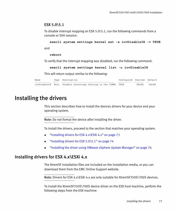
ESX 5.0\5.1
To disable interrupt mapping on ESX 5.0\5.1, run the following commands from a console or SSH session:
esxcli system settings kernel set -s iovDisableIR -v TRUE
and
reboot
To verify that the interrupt mapping was disabled, run the following command:
esxcli system settings kernel list -o iovDisableIR
This will return output similar to the following:
Name Type Description Configured Runtime Default----------- ---- --------------------------------------- ---------- ------- --iovDisableIR Bool Disable Interrrupt Routing in the IOMMU TRUEE FALSE FALSE
Installing the driversThis section describes how to install the devices drivers for your device and your operating system.
Note: Do not format the device after installing the driver.
To install the drivers, proceed to the section that matches your operating system.
◆ “Installing drivers for ESX 4.x\ESXi 4.x” on page 73
◆ “Installing drivers for ESX 5.0\5.1” on page 74
◆ “Installing the driver using VMware vSphere Update Manager” on page 76
Installing drivers for ESX 4.x\ESXi 4.x
The XtremSF installation files are included on the installation media, or you can download them from the EMC Online Support website.
Note: Drivers for ESX 4.x\ESXi 4.x are only suitable for XtremSF350S\700S devices.
To install the XtremSF350S\700S device driver on the ESX host machine, perform the following steps from the ESX machine:

74 EMC XtremSF • User Guide for VMware
XtremSF350\700\1400\350S\700S Installation
1. From the installation media, from the directory for your operating system and device model, extract and copy the following file from mtip32xx-block-1.0.5-esx41-cert.zip to the ESX host:
vmware-esx-drivers-block-mtip32xx-400.1.0.5-1OEM.x86_64.vib
2. Stop all virtual machines on the ESX host.
3. From the ESX host, as root user, enter maintenance mode by executing the following command:
vim-cmd hostsvc/maintenance_mode_enter
4. Install the driver by executing the following command:
esxupdate update -b vmware-esx-drivers-block-mtip32xx-400.1.0.5-1OEM.x86_64.vib --nosigcheck
5. Restart the machine.
6. Exit maintenance mode by executing the following command:
vim-cmd hostsvc/maintenance_mode_exit
Installation is complete.
Note: Do not format the device after installing the driver.
Installing drivers for ESX 5.0\5.1
This section describes how to install the device driver for ESX 5.0\5.1. This task may require multiple restarts.
The installation files are included on the installation media, or you can download them from the EMC Online Support website.
To install the device driver on the ESX host machine, perform the following steps from the ESX machine:

Installing the drivers 75
XtremSF350\700\1400\350S\700S Installation
1. From the installation media, from the directory for your operating system and device model, copy the mtip32xx-scsi-2.6.7-esx50-cert.zip file to the ESX host.
Note: For XtremSF350 devices, install the files located in the directories for XtremSF700\1400 devices.
2. Stop all virtual machines on the ESX host.
3. From the ESX host, as “root” user, enter maintenance mode by typing the following command:
vim-cmd hostsvc/maintenance_mode_enter
4. Install the driver by typing the following command:
esxcli software vib install -d <full_path_to_zip_file>
5. Restart the host machine.
6. Exit maintenance mode by typing the following command:
vim-cmd hostsvc/maintenance_mode_exit
Note: Do not format the device after installing the driver.
7. Driver installation is complete. Proceed to “Installing the management CLI” on page 85.
Verifying proper installation
This section describes how to verify that the drivers were installed properly.
To verify proper installation:
◆ Type the following command:
esxcli software vib list | grep mtip
A message similar to the following is displayed: scsi-mtip32xx-scsi 2.5.8-1OEM.500.0.0.472560 Micron VMwareCertified 2012-04-26

76 EMC XtremSF • User Guide for VMware
XtremSF350\700\1400\350S\700S Installation
Installing the driver using VMware vSphere Update Manager
This section describes how to install the device driver bundle using vSphere Update Manager (VUM). The device driver bundle is supplied on your device’s installation media, in the directory for your operating system and device model.
Note: For XtremSF350 devices, install the files located in the directories for XtremSF700\1400 devices.
You must restart the host machine after installing the driver.
To install the driver using VUM, follow these steps:
1. In the vSphere Client’s Update Manager Administration window, click the Patch Repository tab.

Installing the drivers 77
XtremSF350\700\1400\350S\700S Installation
2. Click Import Patches. The Import Patches window is displayed.
a. Type the path and filename of the device driver bundle for your device (in ZIP file format) in the Patches.zip file box, or click Browse to navigate to the file.
b. Click Next. The upload process begins, and may last for several minutes. Do not close the window until the upload is complete.
c. Click Finish to confirm the import.

78 EMC XtremSF • User Guide for VMware
XtremSF350\700\1400\350S\700S Installation
3. Confirm that the driver is now listed in the patch repository.
4. In the Update Manager Administration window, click the Baselines and Groups tab.
5. Click Create. The New Baseline window is displayed.
6. Type a baseline name in the Name box, select the Host Extension option, and click Next.

Installing the drivers 79
XtremSF350\700\1400\350S\700S Installation
7. Select the patch in the bottom pane, click the Up arrow, and click Next.

80 EMC XtremSF • User Guide for VMware
XtremSF350\700\1400\350S\700S Installation
8. Click Finish.

Installing the drivers 81
XtremSF350\700\1400\350S\700S Installation
The baseline that you created is displayed on the Baselines and Groups tab.
9. In the Update Manager Administration window, Update Manager tab, click Attach. The Attach Baseline or Group window is displayed.

82 EMC XtremSF • User Guide for VMware
XtremSF350\700\1400\350S\700S Installation
10. Select the Extension Baseline that you created earlier, and click Attach..

Installing the drivers 83
XtremSF350\700\1400\350S\700S Installation
11. In the vSphere Client main window, click Stage.

84 EMC XtremSF • User Guide for VMware
XtremSF350\700\1400\350S\700S Installation
12. When staging is complete, click Remediate. The Remediate window is displayed.
13. Ensure that the baseline that you created is selected, click Next twice, and then click Finish.
14. Click Remediate again. The Remediate window is displayed.
a. In the left pane, click Patches and Extensions, select the device patch, and click Next.
b. Type a task name and a task description in the corresponding boxes, and select the time that you want to perform the remediation. Click Next.
c. Click Finish. The remediation will be performed at the time that you specified. The driver installation is complete.
15. Install the management CLI as described in “Installing the management CLI” on page 85 (ESX5.x only). Then perform other configuration procedures, as described in “XtremSF350S\700S\350\700\1400 Configuration” on page 87.
For additional vSphere Update Manager details, refer to your VMware documentation.

Removing the device driver from the ESX host 85
XtremSF350\700\1400\350S\700S Installation
Installing the management CLI
This section describes how to install the management CLI.
Note: ESX\ESXi 4.x do not support the Management CLI.
To install the CLI:
1. From the installation media, from the directory for your operating system and device model, copy the file vmw-esx-micron-rssdm-2.13.7077.04.vib to the ESX host.
Note: For XtremSF350 devices, install the files located in the directories for XtremSF700\1400 devices.
2. Type the following command: esxcli software vib install –v <full_path_to_vib_bundle>
3. Depending on your ESX version, add this line to one of the following files:
export PATH=$PATH:/opt/micron/bin
• ESX 5.1—add the line to /etc/profile.local
• ESX 5.0—add the line to /etc/profile
4. Save the file. Installation is complete.
5. Log out and log back in before you start using RSSDM.
Removing the device driver from the ESX hostThis section describes how to remove the XtremSF300S\350S\700S\350\700\1400 device driver from ESX hosts. Proceed to the section that matches your operating system.
ESX4.x and ESXi4.x
This section describes how to remove the device driver from ESX4.x and ESXi 4.x hosts.
1. Stop, or migrate all virtual machines on the ESX host.

86 EMC XtremSF • User Guide for VMware
XtremSF350\700\1400\350S\700S Installation
2. From the ESX host, as root user, enter maintenance mode by typing the following command:
vim-cmd hostsvc/maintenance_mode_enter
3. Query the installed bulletins by typing the following command:
esxupdate query
The driver bulletin you are looking for is vmware-esx-drivers-scsi-mpt2sas*.vib
4. Remove the driver by typing the following command:
esxupdate -b <bundle_name_to_remove> remove
where bundle_name_to_remove is the bulletin identified in the previous step
ESX5.0 and ESX5.1
This section describes how to remove the device driver from ESX5.0 hosts.
1. Stop, or migrate all virtual machines on the ESX host.
2. From the ESX host, as root user, enter maintenance mode by typing the following command:
vim-cmd hostsvc/maintenance_mode_enter
3. Query the installed driver by typing the following command:
esxcli software vib list|grep mtip
The driver which you are looking for is either block-mtip32xx or scsi-mtip32xx-scsi*
4. Remove the driver by typing the following command:
esxcli software vib remove -n <bundle_name_to_remove>
where <bundle_name_to_remove> is identified in the previous step.
Restart the host machine.

RSSDM CLI 87
XtremSF350S\700S\350\700\1400 Configuration
CHAPTER 7XtremSF350S\700S\350\700\1400 Configuration
This chapter describes how to configure your XtremSF350S\700S\350\700\1400 device using the RSSDM CLI (on ESX 5.x only).
RSSDM CLIThe RSSDM command line interface (CLI) provides a list of commands for managing and monitoring XtremSF350S\700S\350\700\1400 devices in a local system.
Note: RSSDM CLI can not be used on ESX4.x or ESXi4.x
The following tasks can be performed using the CLI:
◆ Formatting a device (using the secure erase and sanitize block erase operations)
◆ Updating (upgrading) unified binary image and base firmware
◆ Configuring device settings
◆ Retrieving debug data
The following information can be retrieved using the RSSDM CLI:
◆ Device parameters/properties: Product information that includes the serial number, model number, firmware revision number, and driver type. In addition, it displays the device’s PCIe information that includes the information retrieved from the device’s PCIe registers, event log, and firmware log.
◆ Performance monitoring information: Statistics about the device’s current input/ output per second (IOPS) and the current load.

88 EMC XtremSF • User Guide for VMware
XtremSF350S\700S\350\700\1400 Configuration
Topics in this section include:
◆ About the RSSDM CLI ....................................................................................... 88◆ Managing a device using the RSSDM CLI .......................................................... 91◆ Displaying device information using the RSSDM CLI........................................ 100
About the RSSDM CLI
This section describes basic information about using the RSSDM CLI. Topics include:
◆ Running the RSSDM CLI.................................................................................... 88◆ Common RSSDM CLI command options............................................................ 88◆ Running RSSDM CLI in silent mode................................................................... 88◆ Saving command output using the RSSDM CLI.................................................. 89
Running the RSSDM CLIRunning the CLI in VMware:
1. In command line, type rssdm
2. To view CLI menu options, type rssdm -?
3. To view CLI sub-options, type rssdm <main_option> -?
where <main_option> is the name of the main menu option.
Common RSSDM CLI command optionsThe RSSDM CLI provides the following options for all commands:
◆ -r: CLI runs in silent mode.
◆ -n: Retrieves specified information for the given Drive ID.
◆ -s: Saves the output of the command to the specified file.
◆ -p: Password required.
◆ rssdm <main_option> -?: Provides detailed usage information for the specified main option.
Running RSSDM CLI in silent modeUse the following instructions to run RSSDM CLI in silent mode. In silent mode, the CLI does not display output to the screen and does not request user input during operation. If a command requires user confirmation, the default input value (yes) is used for those commands.
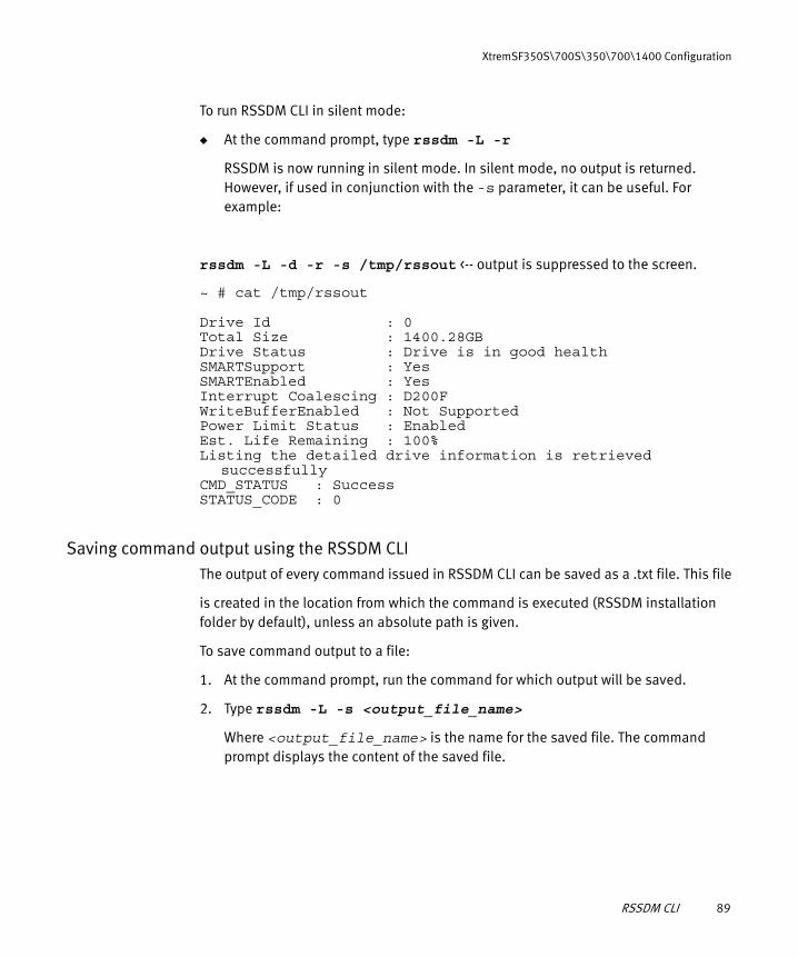
RSSDM CLI 89
XtremSF350S\700S\350\700\1400 Configuration
To run RSSDM CLI in silent mode:
◆ At the command prompt, type rssdm -L -r
RSSDM is now running in silent mode. In silent mode, no output is returned. However, if used in conjunction with the -s parameter, it can be useful. For example:
rssdm -L -d -r -s /tmp/rssout <-- output is suppressed to the screen.
~ # cat /tmp/rssout
Drive Id : 0Total Size : 1400.28GBDrive Status : Drive is in good healthSMARTSupport : YesSMARTEnabled : YesInterrupt Coalescing : D200FWriteBufferEnabled : Not SupportedPower Limit Status : EnabledEst. Life Remaining : 100%Listing the detailed drive information is retrieved
successfullyCMD_STATUS : SuccessSTATUS_CODE : 0
Saving command output using the RSSDM CLIThe output of every command issued in RSSDM CLI can be saved as a .txt file. This file
is created in the location from which the command is executed (RSSDM installation folder by default), unless an absolute path is given.
To save command output to a file:
1. At the command prompt, run the command for which output will be saved.
2. Type rssdm -L -s <output_file_name>
Where <output_file_name> is the name for the saved file. The command prompt displays the content of the saved file.

90 EMC XtremSF • User Guide for VMware
XtremSF350S\700S\350\700\1400 Configuration
Example output:
~ # rssdm -L -d -s /tmp/rssout
Drive Id : 0Total Size : 1400.28GBDrive Status : Drive is in good healthSMARTSupport : YesSMARTEnabled : YesInterrupt Coalescing : D200FWriteBufferEnabled : Not SupportedPower Limit Status : EnabledEst. Life Remaining : 100%
Listing the detailed drive information is retrieved successfullyCMD_STATUS : SuccessSTATUS_CODE : 0
Copyright (C) 2013 Micron Technology, Inc.
~ # cat /tmp/rssout
Drive Id : 0Total Size : 1400.28GBDrive Status : Drive is in good healthSMARTSupport : YesSMARTEnabled : YesInterrupt Coalescing : D200FWriteBufferEnabled : Not SupportedPower Limit Status : EnabledEst. Life Remaining : 100%
Listing the detailed drive information is retrieved successfullyCMD_STATUS : SuccessSTATUS_CODE : 0

RSSDM CLI 91
XtremSF350S\700S\350\700\1400 Configuration
Managing a device using the RSSDM CLI
This section describes how to perform common device management tasks using the RSSDM CLI. Topics include:
◆ Performing a Secure Erase................................................................................ 91◆ Performing a Sanitize Block Erase .................................................................... 92◆ Checking a device’s firmware version ............................................................... 93◆ Updating a Unified Binary Image (upgrading base firmware)............................. 94◆ Displaying UBI file details................................................................................. 95◆ Configuring the interrupt coalescing settings.................................................... 96◆ Retrieving debug data ...................................................................................... 97◆ Enabling or disabling power management ........................................................ 99
Performing a Secure EraseUse the rssdm -X command to perform a secure erase (format) on a specified XtremSF350S\700S\350\700\1400 device.
A secure erase operation completely formats the XtremSF350S\700S\350\700\1400 device. Before you perform a secure erase, backup important data. For more information about the difference between secure erase and sanitize block erase operations, see the explanation in “vgc-secure-erase” on page 49.
Command syntax:
rssdm -X -n <drive-id> -p <password> [-r] [-s <out_filename>]
To perform a secure erase on a device:
1. At the command prompt, type rssdm -X -p <password> -n <drive_ID>.
Where <password> is ffff and <drive_ID> is the device’s Drive ID number. The RSSDM CLI asks whether you want to continue with the operation.
2. Type Y
A message indicates that the secure erase is in progress. When finished, a message indicates that the operation was successful.

92 EMC XtremSF • User Guide for VMware
XtremSF350S\700S\350\700\1400 Configuration
Example output:
# rssdm -X -p ffff -n 1Secure Erase will remove all the user data.Are you sure you want to continue(Y|N):ySecure Erase will take a few minutes to complete. Please wait..................................................................
................................................................
.........................................
Drive Id : 1Secure erase operation completed successfully.CMD_STATUS : SuccessSTATUS_CODE : 0
Performing a Sanitize Block EraseUse the rssdm -X -B command to perform a sanitize block erase on a specified device.
A sanitize block erase operation completely formats the XtremSF350S\700S\350\700\1400 device. Before you perform a sanitize block erase operation, backup important data. For more information about the difference between secure erase and sanitize block erase operations, see the explanation in “vgc-secure-erase” on page 49.
Command Syntax:
rssdm -X -B -n <drive_id> [-r] [-s <out_filename>]
To perform a sanitize block erase operation on a device:
1. At the command prompt, type rssdm -X -B -n <drive_id>
Where <drive_id> is the device’s Drive ID number. The RSSDM CLI asks whether you want to continue with the operation.
2. Type Y.
A message indicates that the sanitize block erase operation is in progress. When finished, a message indicates that the operation was successful.

RSSDM CLI 93
XtremSF350S\700S\350\700\1400 Configuration
Example output:
# rssdm -X -B -n 1Block Erase Sanitize operation will erase all user data blocks.Are you sure you want to continue(Y|N):yBlock Erase Sanitize operation will take a long time, please wait..................................................................
................................................................
......................................
Drive Id : 1Sanitize Block Erase Succeeded
CMD_STATUS : SuccessSTATUS_CODE : 0
Checking a device’s firmware versionUse the following instructions to check which version of firmware is currently installed on an XtremSF350S\700S\350\700\1400 device.
Command Syntax:
rssdm -L
To check the firmware version:
◆ At the command prompt, type rssdm -L The command prompt displays the firmware version (FW-Rev).
Example output:
# rssdm -L
Drive Id : 0Device Name : rssdaModel No : EMC P420m-MTFDGAR1T4MAX 118033218EMC Model No : PCIEHHM-1400MSerial No : 00000000131102046D5CFW-Rev : B2072804Total Size : 1400.28GBDrive Status : Drive is in good healthPCI Path (B:D:F) : 83:00.0Vendor : EMCTemp(C) : 59
Drive information is retrieved successfullyCMD_STATUS : SuccessSTATUS_CODE : 0

94 EMC XtremSF • User Guide for VMware
XtremSF350S\700S\350\700\1400 Configuration
Updating a Unified Binary Image (upgrading base firmware)The UBI image is a combination of firmware, UEFI driver, and option ROM image. Use the following instructions to update the unified binary image (UBI) for an XtremSF350S\700S\350\700\1400 device. The UBI file can be obtained from the device’s installation CD or Support Pack.
Command Syntax:
rssdm -T <UBI_img_file> [-o|-b] -n <drive_id> [,<drive_id>..]] [-r] [-s <out_filename>]
To update a UBI:
1. At the command prompt, type rssdm –T <UBI_img_file> -n <drive_ID>
Where <UBI_img_file> is the UBI file name, and <drive_ID> is the device’s Drive ID number. The RSSDM CLI asks whether you want to continue with the operation.
2. Type Y
A message indicates that the UBI update is in progress, and when it is finished, a message indicates that the operation was successful.
3. Shut down (power off) and power up the host machine.
Options Description
-o By default, UBI image validation is done. However, if this option is specified, it overrides the validation of the UBI image before image update.
-b This option updates the base firmware from the UBI. Other images present in the UBI are not updated.

RSSDM CLI 95
XtremSF350S\700S\350\700\1400 Configuration
Example output:
# rssdm -T B138.00.04.ubi -n 1
Trying to update from current firmware B206.02.04 to B207.28.04. Are you sure you want to continue(Y|N):y
Unified Image update for drive 1 will take a few seconds to complete.
Please wait........................................................
Drive Id : 1Unified image update operation completed successfully.Power cycle the server for the downloaded Unified Image to take
effect.
CMD_STATUS : SuccessSTATUS_CODE : 0
Copyright (C) 2013 Micron Technology, Inc.
## rssdm -L -n 1
Drive Id : 1Device Name : rssdaModel No : EMC P420m-MTFDGAR700MAX 118033217EMC Model No : PCIEHHM-700MSerial No : 00000000131102046D8FFW-Rev : B2072804Total Size : 700.15GBDrive Status : Drive is in good healthPCI Path (B:D:F) : 83:00.0Vendor : EMCTemp(C) : 44
Drive Id : 1Drive information is retrieved successfullyCMD_STATUS : SuccessSTATUS_CODE : 0
Displaying UBI file detailsUse the following option to display the details of the images contained within the UBI file.
Command Syntax:
rssdm -T <UBI_img_file> -d

96 EMC XtremSF • User Guide for VMware
XtremSF350S\700S\350\700\1400 Configuration
To display UBI file details:
◆ At the command prompt, type rssdm -T <UBI_img_file> -d
Where <UBI_img_file> is the name of the UBI image file. The file details are displayed.
Example output:
# rssdm -T B137.00.04.ubi -dP320-Firmware-Rev : B157.00.04P420-Firmware-Rev : B207.28.04Oprom-Rev : 1.6
UBI image version retrieved successfullyCMD_STATUS : SuccessSTATUS_CODE : 0
Configuring the interrupt coalescing settingsUse the following instructions to configure the interrupt coalescing settings.
Interrupt coalescing is the process of taking successive command completion events and coalescing them into a single interrupt. When a high queue depth is used on an XtremSF350S\700S\350\700\1400 device, this coalescing leads to fewer system interrupts, lower CPU utilization, and higher IOPS. For lower queue depth I/O activity, coalescing can increase latency. Changing this value increases or decreases the internal timeout length, enabling more or less I/Os to be completed with a single interrupt. The recommended interrupt coalescing values are D200F, D801F, and D020F.
Command Syntax:
rssdm -M [-i] -n <drive_id> [-r] [-s <out_filename>]
Options Description
-d Displays versions of FW, Oprom and UEFI images of the UBI image

RSSDM CLI 97
XtremSF350S\700S\350\700\1400 Configuration
To configure the interrupt coalescing value for a device:
1. At the command prompt, type rssdm –M –i <coalescing_value> -n <drive_ID>
2. Where <coalescing_value> is the new interrupt coalescing value (D200F, D801F, or D020F), and <drive_ID> is the device’s Drive ID number.
The RSSDM CLI asks whether you want to continue with the operation.
3. Type Y
A message indicates that the operation was successful.
Example output:
# rssdm -M -i D801F -n 0D801F - This setting is useful if you are dealing with high queue
depth I/O activity. This setting increases the internal timeout value allowing more I/Os to be posted complete with a single interrupt.
Are you sure you want to continue(Y|N):y
Drive Id : 0Interrupt Coalescing value is changed successfully.Restart the server to take effect.Any change to Write Buffer or Power Management prior to reboot will
negate this change therefore it is recommended to reboot immediately.
CMD_STATUS : SuccessSTATUS_CODE : 0
Retrieving debug dataUse the following instructions to retrieve debug data for an XtremSF350S\700S\350\700\1400 device. If using VMware, debug data is saved as a .tar file. Otherwise, debug data is saved as a .zip file. Debug data from the device and operating system is provided by you to help debug any potential issues.
Options Description
-i Sets the interrupt coalescing value to the specified drive

98 EMC XtremSF • User Guide for VMware
XtremSF350S\700S\350\700\1400 Configuration
Command Syntax:
rssdm -P <zip_or_tar_file_name> -n <drive_id> [-r] [-s <out_filename>]
To retrieve debug data for a device:
◆ At the command prompt, type rssdm –P <zip_or_tar_file_name> -n <drive ID>
Where <zip_or_tar_file_name> is the name of the file that will contain the debug data. and <drive_ID> is the device’s Drive ID number. If a file path is not specified, the .zip or .tar file is saved to the RSSDM install directory. A message indicates that the operation was successful.
Example output:
# rssdm -P rssdmzip.zip -n 1
Zip file is created on the specified location
Drive Id : 1Debug data has been retrieved successfullyCMD_STATUS : SuccessSTATUS_CODE : 0
Copyright (C) 2013 Micron Technology, Inc.
# ls -l rssdmzip.zip-rw-r--r--. 1 root root 24870 May 15 16:03 rssdmzip.zip[root@fpdqe049 ~]#
Enabling or disabling the write buffer settingThe write buffer setting enables the Xtrem350S\700S device’s write cache. This setting is enabled by default. The data in the device’s write cache generates an acknowledgment (instead of waiting for the data to be transferred to Flash memory before sending the acknowledgment). This results in lower latency on the acknowledgment response, which can improve write performance. However, any data in the write cache not yet transferred to the Flash memory may be lost during an unsafe power loss. The host would then have to rewrite the data on the next power cycle. Additionally, during an unsafe power loss, a UECC error may occur. Devices receiving this error cannot be recovered by Secure Erase.
Note: XtremSF350\700\1400 devices do not support configuration of this option. The write buffer is enabled in these devices.

RSSDM CLI 99
XtremSF350S\700S\350\700\1400 Configuration
Command Syntax:
rssdm -M -w (0|1) -n <drive_id>
To enable or disable the write buffer setting of XtremSF350S\700S devices:
1. At the command prompt, type rssdm -M -w (0|1) -n <drive_ID>
where <drive_ID> is the device’s Drive ID number. The RSSDM CLI displays a warning message about enabling the write buffer setting.
2. Review the message and then type Y to continue. A message indicates that the setting was changed successfully.
Enabling or disabling power managementIn some high-performance cases, the XtremSF350S, XtremSF700S and XtremSF1400 devices can exceed the 25W maximum indicated by its specifications. To prevent this from occurring, enable power management to keep the device’s power usage at or below 25W. When power management is enabled, WRITE performance is throttled to limit the device’s power usage to 25W.
Note: This feature is not supported by XtremSF350 and XtremSF700 devices. If you try to change this setting on these devices, a warning message is displayed.
Command Syntax:
rssdm -M [-i|-w|-p] -n <drive_id> [-r] [-s <out_filename>]
Options Description
-w Enables or disables the write buffer on the specified drive.0 disables the write buffer1 enables the write buffer
Options Description
-p Enables or disables power limiting on the specified drive0 disables power limiting1 enables power limiting

100 EMC XtremSF • User Guide for VMware
XtremSF350S\700S\350\700\1400 Configuration
To enable or disable power management on a device:
◆ At the command prompt, type rssdm -M -p 1 -n <drive_ID> to enable power management, or rssdm -M -p 0 -n <drive_ID> to disable power management,
where <drive_ID> is the device’s Drive ID number. A message indicates that the operation was successful.
Example output for disabling power limiting:
# rssdm -M -p 0 -n 0Are you sure you want to continue(Y|N):y
Drive Id : 0Power limit is disabled successfully.CMD_STATUS : SuccessSTATUS_CODE : 0
Example output for enabling power limiting:
~ # rssdm -M -p 1 -n 0Are you sure you want to continue(Y|N):y
Drive Id : 0Power limit is enabled successfully.CMD_STATUS : SuccessSTATUS_CODE : 0
Displaying device information using the RSSDM CLI
This section describes how to display information about the XtremSF350\700S\350\700\1400 devices in a system using the RSSDM CLI. The following topics describe the details that RSSDM gathers and displays:
◆ Displaying details for all devices in the host system ....................................... 101◆ Displaying details for a specific device ........................................................... 102◆ Displaying detailed drive information ............................................................. 103◆ Displaying FTL rebuild status .......................................................................... 105◆ Displaying PCIe information, including PCIe address ...................................... 106◆ Displaying driver information ......................................................................... 107

RSSDM CLI 101
XtremSF350S\700S\350\700\1400 Configuration
Displaying details for all devices in the host systemUse the following instructions to view details for all XtremSF350S\700S\350\700\1400 devices in the host system, including the model number, serial number, capacity, and status of each device. All measurements for storage are displayed in gigabytes in the RSSDM CLI.
Note: An error message is displayed if no devices are connected to the host system.PCI Path is displayed in hexadecimal value.
Command Syntax:
rssdm -L [-d|-P|-f] [-n <drive_id>] [-r ] [-s <out_filename>]
To display information about all devices in the host system:
◆ At the command prompt, type rssdm -L
The RSSDM CLI displays information about all XtremSF350S\700S\350\700\1400 devices in the host system.
If an FTL rebuild is in process, rebuild status is displayed. For more information, see “Displaying FTL rebuild status” on page 105.
Options Description
-d Lists drive specific details for all devices, or for the specified device
-P Lists specific PCIe details for all devices, or for the specified device
-f Lists details for the devices in FTL rebuild state

102 EMC XtremSF • User Guide for VMware
XtremSF350S\700S\350\700\1400 Configuration
Example output:
~ # rssdm -L
Drive Id : 0Device Name : rssdaModel No : EMC P420m-MTFDGAR1T4MAX 118033218EMC Model No : PCIEHHM-1400MSerial No : 00000000131102046D5CFW-Rev : B2072804Total Size : 1400.28GBDrive Status : Drive is in good healthPCI Path (B:D:F) : 83:00.0Vendor : EMCTemp(C) : 57
Drive information is retrieved successfullyCMD_STATUS : SuccessSTATUS_CODE : 0
Displaying details for a specific deviceUse the following instructions to view details for a specific XtremSF350S\700S\350\700\1400 device in the host system, including the model number, serial number, capacity, and status of each device. All measurements for storage are displayed in gigabytes in the RSSDM CLI.
Command Syntax:
rssdm -L [-d|-P|-f] [-n <drive_id>] [-r ] [-s <out_filename>]
Options Description
-d Lists drive specific details for all devices, or for the specified device
-P Lists specific PCIe details for all devices, or for the specified device
-f Lists details for the devices in FTL rebuild state

RSSDM CLI 103
XtremSF350S\700S\350\700\1400 Configuration
To display information about a specific device in the host system:
◆ At the command prompt, type rssdm -L -n <drive_ID>
where <drive_ID> is the device’s Drive ID number. The RSSDM CLI displays information about the specified device.
If an FTL rebuild is in process, rebuild status is displayed. For more information, see “Displaying FTL rebuild status” on page 105.
Example output:
~ # rssdm -L -n 0
Drive Id : 0Device Name : rssdaModel No : EMC P420m-MTFDGAR1T4MAX 118033218EMC Model No : PCIEHHM-1400MSerial No : 00000000131102046D5CFW-Rev : B2072804Total Size : 1400.28GBDrive Status : Drive is in good healthPCI Path (B:D:F) : 83:00.0Vendor : EMCTemp(C) : 57
Drive information is retrieved successfullyCMD_STATUS : SuccessSTATUS_CODE : 0
Displaying detailed drive informationUse the following instructions to view detailed information about all available XtremSF350S\700S\350\700\1400 devices in the host system, including:
◆ Drive ID
◆ Total (available) size
◆ Drive status
◆ SMART support status
◆ SMART enabled status
◆ Interrupt coalescing value
◆ Power limit status
◆ Write buffer status
◆ Estimated life remaining

104 EMC XtremSF • User Guide for VMware
XtremSF350S\700S\350\700\1400 Configuration
Command Syntax:
rssdm -L [-d|-P|-f] [-n <drive_id>] [-r ] [-s <out_filename>]
To display detailed drive information:
◆ At the command prompt, type rssdm -L -d
The RSSDM CLI displays detailed information about all XtremSF350S\700S\350\700\1400 devices in the host system.
If an FTL rebuild is in process, rebuild status is displayed. For more information, see “Displaying FTL rebuild status” on page 105.
Example output:
~ # rssdm -L -d
Drive Id : 0Total Size : 1400.28GBDrive Status : Drive is in good healthSMARTSupport : YesSMARTEnabled : YesInterrupt Coalescing : D200FWriteBufferEnabled : Not SupportedPower Limit Status : DisabledEst. Life Remaining : 100%
Listing the detailed drive information is retrieved successfullyCMD_STATUS : SuccessSTATUS_CODE : 0
Options Description
-d Lists drive specific details for all devices, or for the specified device
-P Lists specific PCIe details for all devices, or for the specified device
-f Lists details for the devices in FTL rebuild state

RSSDM CLI 105
XtremSF350S\700S\350\700\1400 Configuration
Displaying FTL rebuild statusUse the following instructions to display the status of a Flash Translation Layer (FTL) table rebuild on one or more XtremSF350S\700S\350\700\1400 devices in the host system. An FTL rebuild automatically occurs when a device powers up after an unexpected power loss. When this happens, the operating system does not recognize the device until the FTL rebuild is complete.
You can check the FTL rebuild status for troubleshooting purposes, when a device is not detected by RSSDM.
Command Syntax:
rssdm -L [-d|-P|-f] [-n <drive_id>] [-r ] [-s <out_filename>]
To display the FTL rebuild status for all XtremSF350S\700S\350\700\1400 devices in the host system:
◆ At the command prompt, type rssdm -L -f
The RSSDM CLI displays information about all devices in FTL rebuild state in the host system. The following example shows an example where an FTL rebuild is not in progress on any devices in the host system.
Example output when no FTL build is in progress:
~ # rssdm -L -f
None of the drives are in FTL rebuild state
FTL Rebuild information is retrieved successfullyCMD_STATUS : SuccessSTATUS_CODE : 0
Options Description
-d Lists drive specific details for all devices, or for the specified device
-P Lists specific PCIe details for all devices, or for the specified device
-f Lists details for the devices in FTL rebuild state
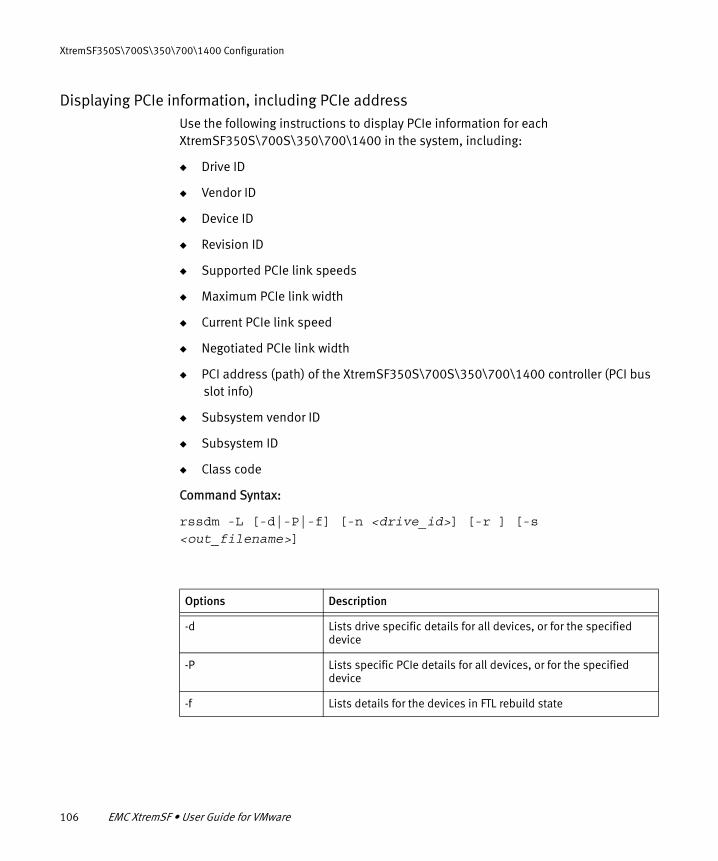
106 EMC XtremSF • User Guide for VMware
XtremSF350S\700S\350\700\1400 Configuration
Displaying PCIe information, including PCIe addressUse the following instructions to display PCIe information for each XtremSF350S\700S\350\700\1400 in the system, including:
◆ Drive ID
◆ Vendor ID
◆ Device ID
◆ Revision ID
◆ Supported PCIe link speeds
◆ Maximum PCIe link width
◆ Current PCIe link speed
◆ Negotiated PCIe link width
◆ PCI address (path) of the XtremSF350S\700S\350\700\1400 controller (PCI bus slot info)
◆ Subsystem vendor ID
◆ Subsystem ID
◆ Class code
Command Syntax:
rssdm -L [-d|-P|-f] [-n <drive_id>] [-r ] [-s <out_filename>]
Options Description
-d Lists drive specific details for all devices, or for the specified device
-P Lists specific PCIe details for all devices, or for the specified device
-f Lists details for the devices in FTL rebuild state

RSSDM CLI 107
XtremSF350S\700S\350\700\1400 Configuration
To display PCIe information:
◆ At the command prompt, type rssdm -L -P
The RSSDM CLI displays PCIe information for each available device in the system.
Example output:
~ # rssdm -L -P
Drive Id : 0VendorId : 1344DeviceId : 5161RevisionId : 03SupportedLinkSpeed : 5.0 GT/s and 2.5 GT/sMaxLinkWidth : 8CurrentLinkSpeed : 5.0 GT/sNegotiatedLinkWidth : 8PCI Path (B:D:F) : 83:00.0SubsystemVendorId : 1344SubsystemId : 3204ClassCode : 018000
PCIe information is retrieved successfullyCMD_STATUS : SuccessSTATUS_CODE : 0
Displaying driver informationUse the following instructions to display information about the driver, host operating system, and host name for a specific XtremSF350S\700S\350\700\1400 device.
Command Syntax:
rssdm –D –n <drive_id> [-r] [-s <out_filename>]
To display driver information:
◆ At the command prompt, type rssdm -D -n <drive_ID>
Where <drive_ID> is the device’s Drive ID number. The RSSDM CLI displays driver information for the specified device.

108 EMC XtremSF • User Guide for VMware
XtremSF350S\700S\350\700\1400 Configuration
Example output:
~ # rssdm -D -n 0Host Name : fbu108107Driver Version : 3.2.1OS Name : Red Hat Enterprise Linux Server release 6.4
(Santiago)
Drive Id : 0Driver information is retrieved successfullyCMD_STATUS : SuccessSTATUS_CODE : 0

Unplanned shutdown 109
XtremSF350S\700S\350\700\1400 Troubleshooting
CHAPTER 8XtremSF350S\700S\350\700\1400 Troubleshooting
This chapter contains troubleshooting suggestions. Topics include:
◆ Unplanned shutdown..................................................................................... 109◆ Thermal shutdown ......................................................................................... 109
Unplanned shutdownAn unplanned shutdown of the XtremSF350S\700S\350\700\1400 device, for instance from a power interruption, can cause the device to enter into a metadata rebuild state, called FTL (Flash Translation Layer). The rebuild may last for several minutes. You can check the FTL status of devices using RSSDM. For more information, see “Displaying FTL rebuild status” on page 105.
Thermal shutdownXtremSF350S\700S\350\700\1400 devices will generate warning messages in the error log, and put the card into Decreased Performance Mode when temperature reaches 87o C. If the device’s temperature reaches 100o C, the device is put into Thermal Shutdown Mode (is taken offline).
If thermal shutdown occurs, airflow around the XtremSF device needs to be increased. Ensure that all environmental requirements mentioned in “Thermal requirements” on page 16 are met. Consider changing system BIOS settings to increase fan speed, or using a different PCI slot. For more information about changing BIOS settings, see “Fan speed settings” on page 18.
When an XtremSF350S\700S\350\700\1400 device shuts down for thermal reasons, you must cold restart the host machine (power cycle). After startup follow Operating System specific steps to resume normal operations.

110 EMC XtremSF • User Guide for VMware
XtremSF350S\700S\350\700\1400 Troubleshooting

PART 4
XtremSF300S
Part 4 of this document explains how to install and uninstall XtremSF300S (PCIEHHS-3XXL) devices. For information about managing these devices, refer to the relevant sections in the VFCache Installation Guide v1.5.3. and the VFCache VMware VSI Plug-In Administration Guide v1.5.3.


Hardware installation 113
XtremSF300S Installation
CHAPTER 9XtremSF300S Installation
This chapter describes how to install and remove XtremSF300S (formerly known as
VFCache devices) hardware and drivers. For information about managing these devices, refer to the relevant sections in the VFCache Installation Guide v1.5.3. and the VFCache VMware VSI Plug-In Administration Guide v1.5.3.
Topics include:
◆ Hardware installation ..................................................................................... 113◆ Enabling use of disks for Direct Attach Storage ............................................... 116◆ Installing the XtremSF300S device driver........................................................ 117◆ Removing the XtremSF300S driver from the ESX host...................................... 118
Hardware installationThis section describes how to install an XtremSF storage device in a host machine. Read the procedures and observe all special notices before you start installing the device.
To avoid electrical shock, disconnect the computer from the main power supply and from any networks before installing the XtremSF device.
Observe Electrostatic Discharge (ESD) precautions while installing or handling XtremSF devices. ESD can damage host machine and/or device components.
IMPORTANT
Before changing your system configuration, ensure that you backup your data. Before saving data on the XtremSF device, ensure that you perform all configuration activities and partitioning.

114 EMC XtremSF • User Guide for VMware
XtremSF300S Installation
IMPORTANT
Before you install the XtremSF device, it is highly recommended that you record the following information, found on the label that is affixed to the device:
◆ Serial number (FNM): ____________________________________
◆ EMC Hardware Kit number : 100– 56x___________________________
◆ Revision number (REV) : ____________________________________
Recording this information before installing the device into your system can ease future troubleshooting operations.
Use only the EMC-supplied brackets. Do not remove the heatsinks during the bracket replacement process. Doing so may cause damage to the device and void the warranty.
To install the device, perform the following steps:
1. Unpack the device and inspect it for damage. Unpack the device in a static-free environment and follow good antistatic grounding procedures. Remove the device from the antistatic bag and carefully inspect the device for damage. If you notice any damage, or if any component is missing, contact EMC customer support.
2. Prepare the computer. Turn off the computer, and disconnect the power cord from the power supply. Disconnect any network cabling. Remove the cover from the chassis.
3. Replace the mounting bracket (system dependent). If required for your system, replace the mounting bracket that ships on the device with the additional bracket supplied with the device. To replace the bracket, remove the mounting screws from the back of the device, install the new bracket, and re-tighten the screws evenly.
4. Insert the XtremSF device in an available PCI Express slot. Locate an empty PCI Express slot. Remove the blank bracket panel on the computer chassis that aligns with the empty PCI Express slot. Save the bracket screw, if applicable.
Align the device to a PCI Express slot. Press down gently, but firmly, to properly seat the device in the slot. Figure 5 on page 115 shows how to insert the device in a PCI Express slot.

Hardware installation 115
XtremSF300S Installation
Figure 5 Installation of the XtremSF device in a typical PCIe slot
Note: The device shape, size, and locations of components might vary from this figure.
5. Secure the bracket to the system’s chassis. Install the bracket screw, if applicable, or engage the system retention mechanism to secure the device to the system’s chassis.
6. Replace the system’s cover, the power cord, the network cabling, and power up the system. Replace the system’s cover, reconnect the power cord, and any network cables. Turn on the power.
The hardware installation is complete.
3_00200-00
64-bit Slot(3.3 V Only)
32-bit Slot(3.3 V Only)
PressHere
PressHere
Bracket Screw
Edge ofHost Board PCI Express x8 Slot

116 EMC XtremSF • User Guide for VMware
XtremSF300S Installation
Enabling use of disks for Direct Attach StorageTo enable use of this device in an XtremSW Cache (formerly VFCache) environment, you must disable interrupt mapping on your ESX host, according to the following instructions. You can do this before or after installing the XtremSF components.
Note: VMware has not reported the need for the following workaround in ESX 4.0.
ESX/ESXi 4.1
To disable interrupt mapping on ESX/ESXi 4.1, run the following commands from a console or SSH session:
esxcfg-advcfg -k TRUE iovDisableIR
and
reboot
To verify that the interrupt mapping was disabled, run the following command:
esxcfg-advcfg -j iovDisableIR
The following output should be returned:
iovDisableIR=TRUE
ESX 5.0\5.1
To disable interrupt mapping on ESX 5.0\5.1, run the following commands from a console or SSH session:
esxcli system settings kernel set -s iovDisableIR -v TRUE
and
reboot
To verify that the interrupt mapping was disabled, run the following command:
esxcli system settings kernel list -o iovDisableIR
This will return output similar to the following:
Name Type Description Configured Runtime Default----------- ---- --------------------------------------- ---------- ------- --iovDisableIR Bool Disable Interrrupt Routing in the IOMMU TRUEE FALSE FALSE

Installing the XtremSF300S device driver 117
XtremSF300S Installation
Installing the XtremSF300S device driverThis section describes how to install the XtremSF300S device driver. The drivers are included on the installation media, according to operating system and device model. You can also download them from the EMC Online Support website.
Installing drivers for ESX 4.1/ESXi 4.1
The XtremSF driver installation files are included on the installation media, or you can download them from the EMC Online Support website.
To install the device driver on the ESX host machine, perform the following steps from the ESX machine:
1. From the installation media, from the directory for your operating system and device model, copy the following driver file to the ESX host:
vmware-esx-drivers-scsi-mpt2sas-400.11.00.00.00.2vmw-1vmw.2.17.00000.x86_64.vib
2. Stop all virtual machines on the ESX host.
3. From the ESX host, as root user, enter maintenance mode by typing the following command:
vim-cmd hostsvc/maintenance_mode_enter
4. Install the driver by typing the following command:
esxupdate update -b vmware-esx-drivers-scsi-mpt2sas-400.11.00.00.00.2vmw-1vmw.2.17.00000.x86_64.vib --nosigcheck
5. Restart the machine.
6. Exit maintenance mode by typing the following command:
vim-cmd hostsvc/maintenance_mode_exit
Installation is complete.
Note: Do not format the XtremSF device after installing the driver.

118 EMC XtremSF • User Guide for VMware
XtremSF300S Installation
Installing drivers for ESX 5.0\5.1
The XtremSF driver installation files are included on the installation media, or you can download them from the EMC Online Support website.
To install the device driver on the ESX host machine, perform the following steps from the ESX machine:
1. From the installation media, from the directory for your operating system and device model, copy the following driver file to the ESX host:
scsi-mpt2sas-11.00.00.00.2vmw-1OEM.500.0.0.472560.x86_64.vib
2. Stop all virtual machines on the ESX host.
3. From the ESX host, as root user, enter maintenance mode by typing the following command:
vim-cmd hostsvc/maintenance_mode_enter
4. Install the driver by typing the following command:
esxcli software vib install -v file:/tmp/LSI/esx5/scsi-mpt2sas-11.00.00.00.2vmw-1OEM.500.0.0.472560.x86_64.vib
Note: You must use the full path.
5. Restart the machine.
6. Exit maintenance mode by typing the following command:
vim-cmd hostsvc/maintenance_mode_exit
Installation is complete.
Note: Do not format the device after installing the driver.
Removing the XtremSF300S driver from the ESX hostThis section describes how to remove the XtremSF300S\350S\700S\350\700\1400 device driver from ESX hosts. Proceed to the section that matches your operating system.

Removing the XtremSF300S driver from the ESX host 119
XtremSF300S Installation
ESX4.x and ESXi4.x
This section describes how to remove the device driver from ESX4.x and ESXi 4.x hosts.
1. Stop, or migrate all virtual machines on the ESX host.
2. From the ESX host, as root user, enter maintenance mode by typing the following command:
vim-cmd hostsvc/maintenance_mode_enter
3. Query the installed bulletins by typing the following command:
esxupdate query
The driver bulletin you are looking for is vmware-esx-drivers-scsi-mpt2sas*.vib
4. Remove the driver by typing the following command:
esxupdate -b <bundle_name_to_remove> remove
where bundle_name_to_remove is the bulletin identified in the previous step
ESX5.0 and ESX5.1
This section describes how to remove the device driver from ESX5.0 hosts.
1. Stop, or migrate all virtual machines on the ESX host.
2. From the ESX host, as root user, enter maintenance mode by typing the following command:
vim-cmd hostsvc/maintenance_mode_enter
3. Query the installed driver by typing the following command:
esxcli software vib list|grep mtip
The driver which you are looking for is either block-mtip32xx or scsi-mtip32xx-scsi*
4. Remove the driver by typing the following command:
esxcli software vib remove -n <bundle_name_to_remove>
where <bundle_name_to_remove> is identified in the previous step.
Restart the host machine.

120 EMC XtremSF • User Guide for VMware
XtremSF300S Installation

121
On-Board Diagnostic LEDs
APPENDIX AOn-Board Diagnostic LEDs
This appendix describes the XtremSF devices’ onboard LEDs. Refer to the appropriate section for your device:
◆ XtremSF550\2200.......................................................................................... 122◆ XtremSF350\700\1400 .................................................................................. 123◆ XtremSF350S\700S ....................................................................................... 125◆ XtremSF300S ................................................................................................. 126

122 EMC XtremSF • User Guide for VMware
On-Board Diagnostic LEDs
XtremSF550\2200There are two onboard LED indicators on the XtremSF550\2200 device. They are visible through the rear bracket and indicate the state of the system. These LEDs can also be used to identify individual devices in a multi-device installation, using the esxcli vgc beacon command. For more information about this command, see “esxcli vgc beacon” on page 55. The following table explains the meaning of each combination of these LEDs:
Table 6 Diagnostic LEDs
Green Amber Status Indicated
OFF OFF No power is supplied to the device
ON ON Power is on, no driver is loaded
ON OFF Power is on, driver is loaded
FLASHING - Data is being read
- FLASHING Data is being written
SLOW FLASHING SLOW FLASHING Beacon is ON

XtremSF350\700\1400 123
On-Board Diagnostic LEDs
XtremSF350\700\1400Three board-mounted, right-angle LEDs shine through holes in the PCI bracket. The meaning of these LEDs is described in the following table.
Table 7 LED indicator codes - XtremSF350\700\1400
HHHL Description
Green LED Amber LED Red LED
Off Off Off Indicates that power is off.
Green/amber flashing alternately (200ms)
Off Indicates that power is on and the device is busy with an internal operation. Wait until the operation is completed. The device state should change to a solid green LED state.
On Off Off Indicates that either an ATA command is being processed or power is on, firmware is initialized, and there is no host activity. The device is operational in either state.
Flashing (30ms) Off Off Indicates that PCIe/NAND host activity is in process. The device is busy, but operational.
Flash error code Flash error code Flash error code Indicates an error code. Error codes are three digits long and are displayed by blinking the first digit, then the second, then the third, with pauses in between and a long pause before repeating. The device is not operational.
Firmware fatal error codes:
112: Failure during DRAM initialization113: Not enough DRAM to run in the configured mode313: DRAM UECC error441: Error during chip initialization411: Incorrect device parameters in the firmware image

124 EMC XtremSF • User Guide for VMware
On-Board Diagnostic LEDs
Off Flashing(30ms)
Off Indicates that the device is backing up internal data to NAND. The device is busy, but operational.
Off On Off Indicates that the device is in safe or “parked” mode. Internal data has been written to NAND and the device is safe to power down.
Off Off On Indicates that the device requires a secure erase or has encountered a critical error. The device is not operational.
Table 7 LED indicator codes - XtremSF350\700\1400 (continued)
HHHL Description
Green LED Amber LED Red LED

XtremSF350S\700S 125
On-Board Diagnostic LEDs
XtremSF350S\700SThree board-mounted, right-angle LEDs shine through holes in the PCI bracket. The meaning of these LEDs is described in the following table.
Table 8 LED indicator codes - XtremSF350S\700S
HHHL Description
Green LED Amber LED Red LED
Off Off Off Indicates that power is off.
Green/amber flashing alternately (200ms)
Off Firmware is rebuilding tables.
On Off Off Power on, no host activity.
Flashing (30ms) Off Off Host, PCI, and NAND activity.
Flash error code Flash error code Flash error code Indicates an error code. Error codes are three digits long and are displayed by blinking the first digit, then the second, then the third with pauses in between and a long pause before repeating. The device is not operational.
Firmware fatal error codes:
112: Failure during DRAM initialization113: Not enough DRAM to run in the configured mode313: DRAM UECC error441: Error during chip initialization411: Incorrect device parameters in the firmware image
Off Flashing(30ms)
Off Meta data is being saved.
Off On Off Safe to power off.
Off Off On Device encountered critical error. Call support.
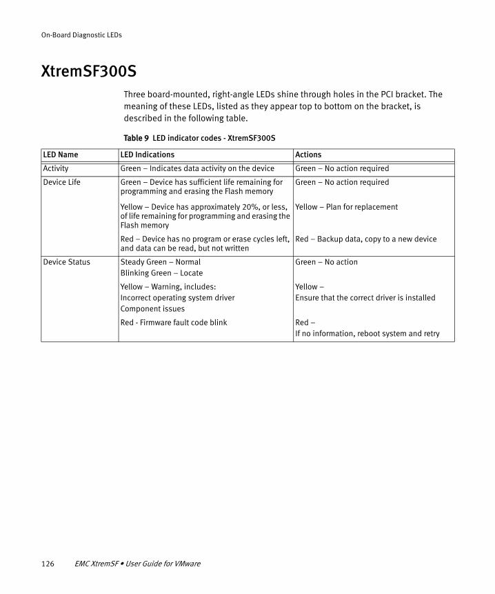
126 EMC XtremSF • User Guide for VMware
On-Board Diagnostic LEDs
XtremSF300SThree board-mounted, right-angle LEDs shine through holes in the PCI bracket. The meaning of these LEDs, listed as they appear top to bottom on the bracket, is described in the following table.
Table 9 LED indicator codes - XtremSF300S
LED Name LED Indications Actions
Activity Green – Indicates data activity on the device Green – No action required
Device Life Green – Device has sufficient life remaining for programming and erasing the Flash memory
Green – No action required
Yellow – Device has approximately 20%, or less, of life remaining for programming and erasing the Flash memory
Yellow – Plan for replacement
Red – Device has no program or erase cycles left, and data can be read, but not written
Red – Backup data, copy to a new device
Device Status Steady Green – NormalBlinking Green – Locate
Green – No action
Yellow – Warning, includes:Incorrect operating system driverComponent issues
Yellow – Ensure that the correct driver is installed
Red - Firmware fault code blink Red – If no information, reboot system and retry

Identifying the PCIe Address of an XtremSF350S\700S\350\700\1400 Device 127
Identifying the PCIe Address of an XtremSF Device
APPENDIX BIdentifying the PCIe Address of an XtremSF Device
This appendix describes the procedures for identifying an XtremSF device’s PCIe address. This address is sometimes required when using the CLI to manage an XtremSF device.
Identifying the PCIe Address of an XtremSF350S\700S\350\700\1400 Device
To display a device’s PCIe address using the RSSDM CLI, type the following command:
rssdm -L -P
The RSSDM CLI displays PCIe information for each available device in the system. The PCIe address is called PCI Path (B:D:F:) in the CLI output. In the following example, the device’s PCIe address is 83:00.0
Example output:
~ # rssdm -L -P
Drive Id : 0VendorId : 1344DeviceId : 5161RevisionId : 03SupportedLinkSpeed : 5.0 GT/s and 2.5 GT/sMaxLinkWidth : 8CurrentLinkSpeed : 5.0 GT/sNegotiatedLinkWidth : 8PCI Path (B:D:F) : 83:00.0SubsystemVendorId : 1344SubsystemId : 3204ClassCode : 018000
PCIe information is retrieved successfullyCMD_STATUS : SuccessSTATUS_CODE : 0

128 EMC XtremSF • User Guide for VMware
Identifying the PCIe Address of an XtremSF Device

129
Upgrading an XtremSF Device
APPENDIX CUpgrading an XtremSF Device
This appendix provides an overview of the procedures required for upgrading an XtremSF device.
Upgrades may require one or more server shutdowns and restarts (including turning power off\power on). Therefore, plan to upgrade your devices at an appropriate time of day.
Ensure that you know the exact model of the device, and that you have the required support pack for your model.
Note: These procedures are not applicable to XtremSF300S devices. No newer versions have been released for these devices.
Note: For XtremSF350S\700S\350\700\1400 devices only, remove the existing XtremSF drivers and management software from your host machine. This may require a system restart.
The following table lists the topics to which you need to refer in order to perform the device upgrade.
Table 10 Procedures for upgrading devices
Procedure Comments
1. Remove the old drivers:
XtremSF550\2200 (optional)See “Removing the XtremSF drivers” on page 40XtremSF350S\700S\350\700\1400See “Removing the device driver from the ESX host” on page 85
Driver removal is not necessary for XtremSF550\2200 devices, because it is possible to upgrade existing drivers.

130 EMC XtremSF • User Guide for VMware
Upgrading an XtremSF Device
2. Install\upgrade the new drivers:
XtremSF550\2200“Installing the XtremSF driver” on page 28“Upgrading the XtremSF drivers” on page 37XtremSF350S\700S\350\700\1400See “Installing the drivers” on page 73
For XtremSF550\2200, upgrade your drivers if they are installed on your system. If you have removed the drivers, install the new drivers using the installation instructions.
For XtremSF350\700S\350\700\1400 devices, you can check which driver is currently installed on your server by using this CLI command:rssdm –D –n <drive_id> [-r] [-s <out_filename> ]If the driver is identical to the one in your support pack, you do not need to upgrade the driver.
3. Upgrade the device’s firmware:
XtremSF550\2200See “Upgrading controller firmware” on page 38XtremSF350S\700S\350\700\1400See “Updating a Unified Binary Image (upgrading base firmware)” on page 94 (using the CLI)
If necessary, upgrade the firmware.
For XtremSF550\2200 devices, the driver will not load successfully if the firmware is incompatible. Error messages such as “unclaimed drive” will be displayed.
For XtremSF350\700S\350\700\1400 devices, you can check which firmware build is currently installed on your server by using this CLI command:rssdm -L -n 1
Note: Firmware upgrades require a hard restart of the system (power off\power on). Schedule the firmware upgrade accordingly.
Table 10 Procedures for upgrading devices (continued)
Procedure Comments


