71
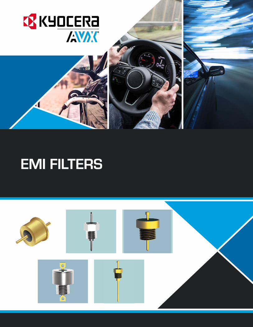
EMI FILTERS
EMI FILTERS
The Important Information/Disclaimer is incorporated in the catalog where these specifications came from or available online at www.avx.com/disclaimer/ by reference and should be reviewed in full before placing any order.
– emi filters –
IMPORTANT INFORMATION/DISCLAIMER
All product specifications, statements, information and data (collectively, the “Information”) in this datasheet or made available on the website are subject to change. The customer is responsible for checking and verifying the extent to which the Information contained in this publication is applicable to an order at the time the order is placed. All Information given herein is believed to be accurate and reliable, but it is presented without guarantee, warranty, or responsibility of any kind, expressed or implied.
Statements of suitability for certain applications are based on KYOCERA AVX knowledge of typical operating conditions for such applications, but are not intended to constitute and KYOCERA AVX specifically disclaims any warranty concerning suitability for a specific customer application or use.
ANY USE OF PRODUCT OUTSIDE OF SPECIFICATIONS OR ANY STORAGE OR INSTALLATION INCONSISTENT WITH PRODUCT GUIDANCE VOIDS ANY WARRANTY.
The Information is intended for use only by customers who have the requisite experience and capability to determine the correct products for their application. Any technical advice inferred from this Information or otherwise provided by KYOCERA AVX with reference to the use of KYOCERA AVX products is given without regard, and KYOCERA AVX assumes no obligation or liability for the advice given or results obtained.
Although KYOCERA AVX designs and manufactures its products to the most stringent quality and safety standards, given the current state of the art, isolated component failures may still occur. Accordingly, customer applications which require a high degree of reliability or safety should employ suitable designs or other safeguards (such as installation of protective circuitry or redundancies) in order to ensure that the failure of an electrical component does not result in a risk of personal injury or property damage.
Unless specifically agreed to in writing, KYOCERA AVX has not tested or certified its products, services or deliverables for use in high risk applications including medical life support, medical device, direct physical patient contact, water treatment, nuclear facilities, weapon systems, mass and air transportation control, flammable environments, or any other potentially life critical uses. Customer understands and agrees that KYOCERA AVX makes no assurances that the products, services or deliverables are suitable for any high-risk uses. Under no circumstances does KYOCERA AVX warrant or guarantee suitability for any customer design or manufacturing process.
Although all product–related warnings, cautions and notes must be observed, the customer should not assume that all safety measures are indicted or that other measures may not be required.

3The Important Information/Disclaimer is incorporated in the catalog where these specifications came from or available online at www.avx.com/disclaimer/ by reference and should be reviewed in full before placing any order.
– emi filters –
Introduction
HIGH-REL EMI FILTERS Noise is the enemy of good engineering design. Properly installed EMI filters suppress such electromagnetic interference on power and signal lines, while allowing desired signals to pass. For critical EMI filter applications, high reliability is of the utmost importance.High reliability applications have diverse requirements, ranging from a need for a long operating life in medical or military systems to avoiding the prohibitive cost of replacing a faulty component in a satellite, undersea cable, or other inaccessible system. High-rel filters satisfy application-critical requirements in many environments:
• Space/Satellite Systems • Military Aircraft • Guidance Systems • Command, Control & Communications (C3) • Missile Systems • Weapon Systems • Radar Systems• Electro Optical Systems •• Electronic Countermeasures •• Electronic Warfare •• Pacemakers • Medication Monitors
HIGH-REL STANDARDS Reliability must be designed into an EMI filter. Every step in its manufacture from material selection through testing and characterization must be considered. To assure conformance to clearly-defined product and performance parameters, specifications have evolved for electrical performance, mechanical configurations, test methods, screening and qualification procedures.KYOCERA AVX Filters delivers high quality EMI filters which meet appli - cable portions of these high-reliability standards: •
• MIL-F-15733• MIL-STD-220• MIL-F-28861• MIL-Q-9858• MIL-STD-202
• MIL-I-45208A• MIL-STD-790• ISO 9000• MIL-C-123• EIA-RS-469
FILTERS AT THE LEADING EDGE KYOCERA AVX Filters Corporation continues to provide innovative solutions to the high performance needs of its customers. It has pioneered many breakthroughs which have advanced the state-of-the-art in this demanding discipline, including: • The first to qualify to the new High-Reliability Filter Spec, MIL-F-28861.
• Facility qualified to MIL-STD-790 during first round of audits for filter manufacturers.
• The first solder-in filter line to offer 400°C installation temperature.
• The first filter line designed to meet the new MIL-Spec requirements for heat rise/reactive current in 125 VAC and 230 VAC 400 Hz applications.
• The first to offer a filter line of hermetically sealed bolt style filters.
CUSTOM AND SEMI-CUSTOM In addition to standard catalog and QPL EMI filters, KYOCERA AVX Filters produces two classes of these special products: Semi-custom and Custom. Semi-custom involves variations in electrical parameters, testing, and limited mechanical changes from standard product designs. Delivery is slightly longer and price is slightly higher than standard products Custom products require longer lead time for design and manufacturing, but give designers freedom to specify nonstandard mechanical and electrical filter designs.KYOCERA AVX Filters dedicates a unique internal part number to every semi-custom and custom component. This insures continued configuration control for each part, allows future changes to be easily implemented, and provides assurance that the design always matches the customer requirements.
ENGINEER TO ENGINEER Our application engineering staff will assist in defining your filter requirements, while recommending advantages, reliability, quality assurance levels, and filter performance at the lowest practical cost. They will help in filter selection and specification, including meeting DESC requirements. SCD models are available to assist you in the design process.A custom filter part number will be assigned exclusively to your SCD. To obtain prompt, professional assistance, call (818) 767-6770.
QUALITY ASSURANCE Quality assurance is built into every stage of manufacturing and testing. KYOCERA AVX Filters controls the entire process, from the capacitor's dielectric formulation through final filter test. This results in absolute traceability by lot number to a specific dielectric batch, as well as the subsequent materials, equipment and employees involved in the tightly-controlled manufacturing and testing process. In addition, critical processes are monitored using SQC, SPC techniques.

1The Important Information/Disclaimer is incorporated in the catalog where these specifications came from or available online at www.avx.com/disclaimer/ by reference and should be reviewed in full before placing any order.
– emi filters –
Filter Product SelectorApplication Notes ...................................................................................................................................................................................................................................... 2
Solder-In Style High Temp EMI FiltersZZ Series – .118 Dia. – Circuits Available - C ........................................................................................................................................................................................... 4
Bolt Style EMI FiltersSA Series – 4-40 Thread - Epoxy Sealed – Circuits Available – C & L ..................................................................................................................................................17
Advanced Technology FiltersMiniature, Subminiature & Microminiature .............................................................................................................................................................................................28Hermetic High Temperature Solder-Ins ..................................................................................................................................................................................................33
Cylindrical Style EMI Filters ........................................................................................................................................................................................................... 34BL Series – .375 Dia. – Button Epoxy Sealed – Circuits Available – C & L ..........................................................................................................................................34
Filter PlatesCustom Designed Filter Plates ................................................................................................................................................................................................................ 52
Filter Design GuideHigh Reliability .......................................................................................................................................................................................................................................... 55
Filter Types ........................................................................................................................................................................................................................................... 58
Filter Design GuideHigh Reliability .......................................................................................................................................................................................................................................... 60
Military Qualified Products ............................................................................................................................................................................................................ 62
How To OrderNotes ........................................................................................................................................................................................................................................................ 64
Table of Contents

2
– emi filters –
The Important Information/Disclaimer is incorporated in the catalog where these specifications came from or available online at www.avx.com/disclaimer/ by reference and should be reviewed in full before placing any order.
Filter Product SelectorApplication Notes

3The Important Information/Disclaimer is incorporated in the catalog where these specifications came from or available online at www.avx.com/disclaimer/ by reference and should be reviewed in full before placing any order.
– emi filters –
Filter Product SelectorApplication Notes
SOLDER-IN HIGH TEMP EMI FILERS
SOLDER-IN HIGH TEMP EMI FILERS
HERMETICALLY SEALED CYLINDRICAL EMI FILERS
HERMETICALLY SEALED CYLINDRICAL EMI FILERS
BOLT STYLE EMI FILERS
FEATURES• Hermetically sealed on one end• C & L Circuit Configurations• Filter Frequency Range: 10MHz to 26GHz• Up to 300C Installation Temperature• Availabe in Miniature Sizes (see page 17-18)
FEATURES• High Capacitance Values Available• Low Profile• Filter Frequency Range: 500KHz to 10GHz• Available in Miniature Sizes (see page 46-47)
FEATURES• Hermetically Sealed on Both Ends• Most Space Available in 0.375/0.410 inch Diameter• Circuit Options:• MIL-F-28861/2, 3, 4, 5 QPL Equivalent• Filter Frequency Range: 30KHz to 10GHz
FEATURES• Custom Designed to Customer Requirements• Up to 300C Installation Temperature• 100% Tested and Burning Prior to Shipment• May be supplied with MIL-F-28861/12, 14, 15 filters installed as available
(see QPL listings)• Can be supplied with filters approved to DESC drawings 88010, 84080, 84081, 84082 or
to KYOCERA AVX filters catalog equivalents design to the requirements MIL-F-28861.
FEATURES• Filter Frequency Range: 1MHz to 10GHz• Available in Miniature Sizes (see page 27-28)
4
– emi filters –
The Important Information/Disclaimer is incorporated in the catalog where these specifications came from or available online at www.avx.com/disclaimer/ by reference and should be reviewed in full before placing any order.
Solder-In Style High Temp EMI Filters
ZZ Series – .118 Dia. – Circuits Available - C

5The Important Information/Disclaimer is incorporated in the catalog where these specifications came from or available online at www.avx.com/disclaimer/ by reference and should be reviewed in full before placing any order.
– emi filters –
Solder-In Style High Temp EMI FiltersZZ Series – .118 Dia. – Circuits Available - C
.118±.002
.020±.005
.110±.005
.140±.020
.400±.020
GLASS SEAL
.140±.005
.030±.002
C
ZZ1
The ZZ series is intended for use as a high reliability alternative to a commonly available commercial filter type. Due to its smaller body diameter, capacitance is limited. It does provide effective filtering in the MICROWAVE frequency spectrum from 100 MHz through 26 GHz. Designed to be soldered into a package, bracket or bulkhead (and maintain hermeticity), it is ideal for high
impedance circuits where large capacitance values are not practical.Alternate lead lengths or special capacitance values are available upon request.Custom packages or bracket assemblies utilizing this feedthru can be furnished to your specifications.
APPLICATIONS
CHARACTERISTICS
SPECIFICATIONS
• High temperature construction withstands 300°C installation temperatures.
• Features rugged monolithic discoidal capacitor construction.
• Glass hermetic seal on one end with epoxy seal on the opposite end.
• High purity gold plating provides excellent solderability or compatibility with thermal and ultrasonic wire bonding.
1. Finish: Gold standard –Silver and solder coat available
2. Material: Case: Cold rolled steel Leads: Alloy 52 steel
3. Operating Temperature Range: -55°C to +125°C
4. Insulation Resistance:At 25°C: 1,000 megohm-microfarad
min., or 100,000 megohms min., whichever is less
At 125°C: 100 megohm-microfarad min., or 10,000 megohms min., whichever is less
5. Dielectric Withstanding Voltage (DWV): R-level designs:
2.0 times rated DC voltageClass B, Class S designs:
2.5 times rated DC voltage
6. DC Resistance (DCR): .01 ohm, maximum
7. Dissipation Factor (DF): 3% maximum8. Rated DC Current: 5 Amps, maximum9. Maximum Installation Temperature:
300°C10. Supplied with 60/40 solder preform for
easy installation
STANDARD CONFIGURATION(See Note 1)
CIRCUIT DIAGRAMS
millimeters (inches)
(See Note 2)
Notes:1. Glass seal on end opposite flange.2. Metric equivalent dimensions given
for information only.
0.05 (.002) 3.05 (.120)0.13 (.005) 3.43 (.135)0.51 (.020) 3.56 (.140)1.02 (.040) 3.68 (.145)2.79 (.110) 10.16 (.400)2.95 (.116) — —

6 The Important Information/Disclaimer is incorporated in the catalog where these specifications came from or available online at www.avx.com/disclaimer/ by reference and should be reviewed in full before placing any order.
– emi filters –
Solder-In Style High Temp EMI FiltersZZ Series – .118 Dia. – Circuits Available - C
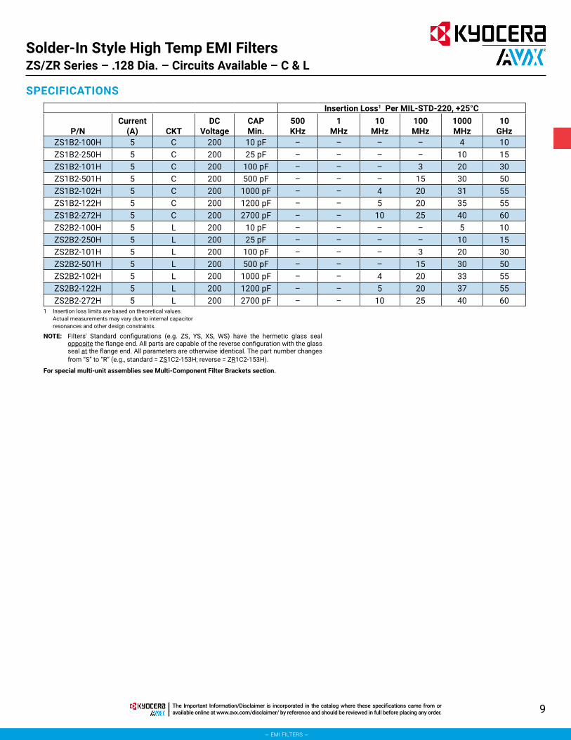
SPECIFICATIONSInsertion Loss1 Per MIL-STD-220, +25°C
P/NCurrent
(A) CKT DC Voltage
CAP Min. (pF) 1 MHz 10 MHz 100 MHz 1000 MHz 10 GHz
ZZ1C3-250H 5 C 50 25 – – – 10 15ZZ1C3-500H 5 C 50 50 – – 1 15 25ZZ1C3-101H 5 C 50 100 – – 3 20 30ZZ1C3-102H 5 C 50 1000 – 4 20 31 55ZZ1C3-152H 5 C 50 1500 – 5 21 42 55ZZ1A3-250H 5 C 100 25 – – – 10 15ZZ1A3-500H 5 C 100 50 – – 1 15 25ZZ1A3-101H 5 C 100 100 – – 3 20 30ZZ1A3-102H 5 C 100 1000 – 4 18 36 55ZZ1A3-152H 5 C 100 1500 – 5 21 42 55ZZ1B3-250H 5 C 200 25 – – – 10 15ZZ1B3-500H 5 C 200 50 – – 1 15 25ZZ1B3-101H 5 C 200 100 – – 3 20 30ZZ1B3-102H 5 C 200 1000 – 4 18 36 55
1 Insertion loss limits are based on theoretical values. Actual measurements may vary due to internal capacitor
resonances and other design constraints.
For special multi-unit assemblies see Multi-Component Filter Brackets section.

7The Important Information/Disclaimer is incorporated in the catalog where these specifications came from or available online at www.avx.com/disclaimer/ by reference and should be reviewed in full before placing any order.
– emi filters –
Solder-In Style High Temp EMI FiltersZS/ZR Series – .128 Dia. – Circuits Available – C & L
The ZS series provides effective filtering in the MICROWAVE frequency spectrum from 10 MHz through 26 GHz. Designed to be soldered into a package, bracket or bulkhead (and maintain hermeticity), it is ideal for high impedance circuits where large capacitance values are not practical. In the “L” section version an internal ferrite bead element provides both inductance
and series resistance (lossy characteristic) which improves insertion loss and provides superior transient performance.Alternate lead lengths or special capacitance values may be ordered.Custom packages or bracket assemblies utilizing this feedthru can be furnished to your specifications.
APPLICATIONS
CHARACTERISTICS
SPECIFICATIONS
• Meets or exceeds the applicable portions of MIL-F-28861/12. See QPL listings.
• High temperature construction withstands 300°C installation temperatures.
• Features rugged monolithic discoidal capacitor construction.
• Glass hermetic seal on one end with epoxy seal on the opposite end.
• High purity gold plating provides excellent solderability or compatibility with thermal and ultrasonic wire bonding.
1. Finish: Gold standard –Silver and solder coat available
2. Material: Case: Cold rolled steel Leads: Alloy 52 steel
3. Operating Temperature Range: -55°C to +125°C
4. Insulation Resistance:At 25°C: 1,000 megohm-microfarad
min., or 100,000 megohms min., whichever is less
At 125°C: 100 megohm-microfarad min., or 10,000 megohms min., whichever is less
5. Dielectric Withstanding Voltage (DWV): R-level designs:
2.0 times rated DC voltageClass B, Class S designs:
2.5 times rated DC voltage
6. DC Resistance (DCR): .01 ohm, maximum
7. Dissipation Factor (DF): 3% maximum8. Rated DC Current: 5 Amps, maximum9. Maximum Installation Temperature:
300°C10. Supplied with 60/40 solder preform for
easy installation11. Insertion Loss for the “C” and “L” circuits
are equivalent due to the saturation characteristic of the ferrite bead element at full rated current. At lower currents the “L” becomes much more effective.
millimeters (inches)
(See Note 4)MIL-F-28861/12 (See Note 2)
Notes:1. Outline drawing shows
standard ZS configuration. Also available with glass seal at the opposite end, ZR reverse configuration.
2. MIL-F-28861/12 style FS70 equivalent to standard ZS configuration. Style FS71 is reverse ZR configuration.
0.05 (.002) 3.25 (.128)0.13 (.005) 3.96 (.156)0.51 (.020) 5.08 (.200)0.76 (.030) 6.4 (.25)0.8 (.03) 15.88 (.625)
2.79 (.110) 18.16 (.715)
STANDARD CONFIGURATION
C
ZS1, ZR1
CIRCUIT DIAGRAMS
ZS2 (See Note 3)
GLASSSEALEND
FLANGEEND
ZR2
GLASSSEALEND
FLANGEEND
Circuit Diagram
DimensionsA
±.005B
Nom.L .200 .715C .110 .625
Dash No. Style001 through 016,
033 and 034 FS70
017 through 032, 035 and 036 FS71
3. For ZS2 or ZR2 L-Section Filters inductor always positioned at epoxy-filled end.
4. Metric equivalent dimensions given for information only.

8 The Important Information/Disclaimer is incorporated in the catalog where these specifications came from or available online at www.avx.com/disclaimer/ by reference and should be reviewed in full before placing any order.
– emi filters –
SPECIFICATIONSInsertion Loss1 Per MIL-STD-220, +25°C
P/NCurrent
(A) CKTDC
VoltageCAPMin.
500KHz
1MHz
10MHz
100MHz
1000MHz
10GHz
ZS1C2-501H 5 C 50 500 pF – – – 15 30 50ZS1C2-102H 5 C 50 1000 pF – – 4 20 31 55ZS1C2-122H 5 C 50 1200 pF – – 5 20 35 55ZS1C2-272H 5 C 50 2700 pF – – 10 25 40 60ZS1C2-502H 5 C 50 5000 pF – – 15 30 45 60ZS1C2-103H 5 C 50 0.010 μF – 4 20 35 48 60ZS1C2-153H 5 C 50 0.015 μF – 7 25 40 50 60ZS2C2-501H 5 L 50 500 pF – – – 15 30 50ZS2C2-102H 5 L 50 1000 pF – – 4 20 33 55ZS2C2-122H 5 L 50 1200 pF – – 5 20 37 55ZS2C2-272H 5 L 50 2700 pF – – 10 25 40 60ZS2C2-502H 5 L 50 5000 pF – – 15 30 45 60ZS2C2-103H 5 L 50 0.010 μF – 4 20 38 50 60ZS2C2-153H 5 L 50 0.015 μF – 7 25 42 50 60ZS1A2-101H 5 C 100 100 pF – – – 3 20 30ZS1A2-501H 5 C 100 500 pF – – – 15 30 50ZS1A2-102H 5 C 100 1000 pF – – 4 20 31 55ZS1A2-122H 5 C 100 1200 pF – – 5 20 35 55ZS1A2-272H 5 C 100 2700 pF – – 10 25 40 60ZS1A2-502H 5 C 100 5000 pF – – 15 30 45 60ZS1A2-103H 5 C 100 0.010 μF – 4 20 35 48 60ZS1A2-153H 5 C 100 0.015 μF – 7 25 40 50 60ZS2A2-100H 5 L 100 10 pF – – – – 5 10ZS2A2-250H 5 L 100 25 pF – – – – 10 15ZS2A2-101H 5 L 100 100 pF – – – 3 20 30ZS2A2-501H 5 L 100 500 pF – – – 15 30 50ZS2A2-102H 5 L 100 1000 pF – – 4 20 33 55ZS2A2-122H 5 L 100 1200 pF – – 5 20 37 55ZS2A2-272H 5 L 100 2700 pF – – 10 25 40 60ZS2A2-502H 5 L 100 5000 pF – – 15 30 45 60ZS2A2-103H 5 L 100 0.010 μF – 4 20 38 50 60ZS2A2-153H 5 L 100 0.015 μF – 7 25 42 50 60
1 Insertion loss limits are based on theoretical values. Actual measurements may vary due to internal capacitor
resonances and other design constraints.NOTE: Filters' Standard configurations (e.g. ZS, YS, XS, WS) have the hermetic glass seal
opposite the flange end. All parts are capable of the reverse configuration with the glass seal at the flange end. All parameters are otherwise identical. The part number changes from “S” to “R” (e.g., standard = ZS1C2-153H; reverse = ZR1C2-153H).
For special multi-unit assemblies see Multi-Component Filter Brackets section.
continued
Solder-In Style High Temp EMI FiltersZS/ZR Series – .128 Dia. – Circuits Available – C & L
9The Important Information/Disclaimer is incorporated in the catalog where these specifications came from or available online at www.avx.com/disclaimer/ by reference and should be reviewed in full before placing any order.
– emi filters –
SPECIFICATIONSInsertion Loss1 Per MIL-STD-220, +25°C
P/NCurrent
(A) CKTDC
VoltageCAPMin.
500KHz
1MHz
10MHz
100MHz
1000MHz
10GHz
ZS1B2-100H 5 C 200 10 pF – – – – 4 10ZS1B2-250H 5 C 200 25 pF – – – – 10 15ZS1B2-101H 5 C 200 100 pF – – – 3 20 30ZS1B2-501H 5 C 200 500 pF – – – 15 30 50ZS1B2-102H 5 C 200 1000 pF – – 4 20 31 55ZS1B2-122H 5 C 200 1200 pF – – 5 20 35 55ZS1B2-272H 5 C 200 2700 pF – – 10 25 40 60ZS2B2-100H 5 L 200 10 pF – – – – 5 10ZS2B2-250H 5 L 200 25 pF – – – – 10 15ZS2B2-101H 5 L 200 100 pF – – – 3 20 30ZS2B2-501H 5 L 200 500 pF – – – 15 30 50ZS2B2-102H 5 L 200 1000 pF – – 4 20 33 55ZS2B2-122H 5 L 200 1200 pF – – 5 20 37 55ZS2B2-272H 5 L 200 2700 pF – – 10 25 40 60
1 Insertion loss limits are based on theoretical values. Actual measurements may vary due to internal capacitor resonances and other design constraints.
NOTE: Filters' Standard configurations (e.g. ZS, YS, XS, WS) have the hermetic glass seal opposite the flange end. All parts are capable of the reverse configuration with the glass seal at the flange end. All parameters are otherwise identical. The part number changes from “S” to “R” (e.g., standard = ZS1C2-153H; reverse = ZR1C2-153H).
For special multi-unit assemblies see Multi-Component Filter Brackets section.
Solder-In Style High Temp EMI FiltersZS/ZR Series – .128 Dia. – Circuits Available – C & L

10 The Important Information/Disclaimer is incorporated in the catalog where these specifications came from or available online at www.avx.com/disclaimer/ by reference and should be reviewed in full before placing any order.
– emi filters –
Solder-In Style High Temp EMI FiltersYS/YR Series – .165 Dia. – Circuits Available – C & L
The YS series provides increased filtering in the MICROWAVE frequency spectrum from 1 MHz through 10 GHz. Previously unavailable in the industry as a solder-in device, this unique design offers higher values of capacitance than were previously available. Designed to be soldered into a package, bracket or bulkhead (and maintain hermeticity), it is ideal for high impedance circuits where large capacitance values are not practical. In the “L” section version an
internal ferrite bead element provides both inductance and series resistance (lossy characteristic) which improves insertion loss and provides superior transient performance.Alternate lead lengths or special capacitance values may be ordered.Custom packages or bracket assemblies utilizing this feedthru can be furnished to your specifications.
APPLICATIONS
CHARACTERISTICS
SPECIFICATIONS
• Meets or exceeds the applicable portions of MIL-F-28861/15. See QPL listings.
• High temperature construction withstands 300°C installation temperatures.
• Features rugged monolithic discoidal capacitor construction.
• Glass hermetic seal on one end with epoxy seal on the opposite end.
• High purity gold plating provides excellent solderability or compatibility with thermal and ultrasonic wire bonding.
1. Plating: Gold standard – Silver available2. Material:
Case: Cold rolled steel Leads: Alloy 52 steel
3. Operating Temperature Range: -55°C to +125°C
4. Insulation Resistance:At 25°C: 1,000 megohm-microfarad
min., or 100,000 megohms min., whichever is less
At 125°C: 100 megohm-microfarad min., or 10,000 megohms min., whichever is less
5. Dielectric Withstanding Voltage (DWV): R-level designs:
2.0 times rated DC voltageClass B, Class S designs:
2.5 times rated DC voltage
6. DC Resistance (DCR): .01 ohm, maximum
7. Dissipation Factor (DF): 3% maximum8. Rated DC Current: 5 Amps, maximum9. Maximum Installation Temperature:
300°C10. Supplied with 60/40 solder preform for
easy installation11. Insertion Loss for the “C” and “L” circuits
are equivalent due to the saturation characteristic of the ferrite bead element at full rated current. At lower currents the “L” becomes much more effective.
millimeters (inches)
(See Note 4) MIL-F-28861/15 (See Note 2)
Notes:1. Outline drawing shows
standard YS configuration. Also available with glass seal at the opposite end, YR reverse configuration.
2. MIL-F-28861/15 style A equivalent to standard YS configuration. Style B is reverse YR configuration.
0.05 (.002) 4.19 (.165)0.13 (.005) 5.08 (.200)0.64 (.025) 6.35 (.250)0.8 (.03) 16.51 (.650)
0.81 (.032) 19.05 (.750)3.81 (.150) — —
Circuit Diagram
DimensionsA
±.005B
Ref.L .250 .750C .150 .650
Dash No. Config.001 through 004 A005 through 008 B
3. For YS2 or YR2 L-Section Filters inductor always positioned at epoxy-filled end.
4. Metric equivalent dimensions given for information only.
STANDARD CONFIGURATION
C
YS1, YR1
CIRCUIT DIAGRAMS
YS2 (See Note 3)
GLASSSEALEND
FLANGEEND
YR2
GLASSSEALEND
FLANGEEND

11The Important Information/Disclaimer is incorporated in the catalog where these specifications came from or available online at www.avx.com/disclaimer/ by reference and should be reviewed in full before placing any order.
– emi filters –
Solder-In Style High Temp EMI FiltersYS/YR Series – .165 Dia. – Circuits Available – C & L
SPECIFICATIONSInsertion Loss1 Per MIL-STD-220, +25°C
P/NCurrent
(A) CKTDC
VoltageCAPMin.
500KHz
1MHz
10MHz
100MHz
1000MHz
10GHz
YS1C2-152H 5 C 50 1500 pF – – 5 21 42 55YS1C2-502H 5 C 50 5000 pF – – 15 34 50 60YS1C2-103H 5 C 50 0.010 μF – 4 20 35 53 60YS1C2-153H 5 C 50 0.015 μF – 7 25 40 55 60YS1C2-203H 5 C 50 0.020 μF – 8 27 41 60 65YS1C2-273H 5 C 50 0.027 μF 4 10 30 42 65 70YS1C2-503H 5 C 50 0.050 μF 9 15 35 44 70 70YS1C2-753H 5 C 50 0.075 μF 12 18 37 46 70 70YS1C2-104H 5 C 50 0.100 μF 14 20 38 48 70 70YS2C2-152H 5 L 50 1500 pF – – 6 22 48 55YS2C2-502H 5 L 50 5000 pF – – 15 35 55 60YS2C2-103H 5 L 50 0.010 μF – 4 20 36 57 60YS2C2-153H 5 L 50 0.015 μF – 7 25 45 60 60YS2C2-203H 5 L 50 0.020 μF – 8 27 46 62 65YS2C2-273H 5 L 50 0.027 μF 4 10 30 48 65 70YS2C2-503H 5 L 50 0.050 μF 9 15 36 50 70 70YS2C2-753H 5 L 50 0.075 μF 12 18 37 51 70 70YS2C2-104H 5 L 50 0.100 μF 14 20 39 52 70 70YS1A2-152H 5 C 100 1500 pF – – 5 21 42 55YS1A2-502H 5 C 100 5000 pF – – 15 34 50 60YS1A2-103H 5 C 100 0.010 μF – 4 20 35 53 60YS1A2-153H 5 C 100 0.015 μF – 7 25 40 55 60YS1A2-203H 5 C 100 0.020 μF – 8 27 41 60 65YS1A2-273H 5 C 100 0.027 μF – 10 30 42 65 70YS1A2-503H 5 C 100 0.050 μF 9 15 35 44 70 70YS1A2-753H 5 C 100 0.075 μF 12 18 37 46 70 70YS2A2-152H 5 L 100 1500 pF – – 6 22 48 55YS2A2-502H 5 L 100 5000 pF – – 15 35 55 60YS2A2-103H 5 L 100 0.010 μF – 4 20 36 57 60YS2A2-153H 5 L 100 0.015 μF – 7 25 45 60 60YS2A2-203H 5 L 100 0.020 μF – 8 27 46 62 65YS2A2-273H 5 L 100 0.027 μF – 10 30 48 65 70YS2A2-503H 5 L 100 0.050 μF 9 15 36 50 70 70YS2A2-753H 5 L 100 0.075 μF 12 18 37 51 70 70
1 Insertion loss limits are based on theoretical values. Actual measurements may vary due to internal capacitor resonances and other design constraints.
NOTE: Filters' Standard configurations (e.g. ZS, YS, XS, WS) have the hermetic glass seal opposite the flange end. All parts are capable of the reverse configuration with the glass seal at the flange end. All parameters are otherwise identical. The part number changes from “S” to “R” (e.g., standard = ZS1C2-153H; reverse = ZR1C2-153H).
For special multi-unit assemblies see Multi-Component Filter Brackets section.
continued

12 The Important Information/Disclaimer is incorporated in the catalog where these specifications came from or available online at www.avx.com/disclaimer/ by reference and should be reviewed in full before placing any order.
– emi filters –
SPECIFICATIONSInsertion Loss1 Per MIL-STD-220, +25°C
P/NCurrent
(A) CKTDC
VoltageCAPMin.
500KHz
1MHz
10MHz
100MHz
1000MHz
10GHz
YS1B2-152H 5 C 200 1500 pF – – 5 21 42 55YS1B2-502H 5 C 200 5000 pF – – 15 34 50 60YS1B2-103H 5 C 200 0.010 μF – 4 20 35 53 60YS1B2-153H 5 C 200 0.015 μF – 7 25 40 55 60YS1B2-203H 5 C 200 0.020 μF – 8 27 41 60 65YS1B2-273H 5 C 200 0.027 μF 4 10 30 42 65 70YS2B2-152H 5 L 200 1500 pF – – 6 22 48 55YS2B2-502H 5 L 200 5000 pF – – 15 35 55 60YS2B2-103H 5 L 200 0.010 μF – 4 20 36 57 60YS2B2-153H 5 L 200 0.015 μF – 7 25 45 60 60YS2B2-203H 5 L 200 0.020 μF – 8 27 46 62 65YS2B2-273H 5 L 200 0.027 μF 4 10 30 48 65 70
1 Insertion loss limits are based on theoretical values. Actual measurements may vary due to internal capacitor resonances and other design constraints.
NOTE: Filters' Standard configurations (e.g. ZS, YS, XS, WS) have the hermetic glass seal opposite the flange end. All parts are capable of the reverse configuration with the glass seal at the flange end. All parameters are otherwise identical. The part number changes from “S” to “R” (e.g., standard = ZS1C2-153H; reverse = ZR1C2-153H).
For special multi-unit assemblies see Multi-Component Filter Brackets section.
Solder-In Style High Temp EMI FiltersYS/YR Series – .165 Dia. – Circuits Available – C & L

13The Important Information/Disclaimer is incorporated in the catalog where these specifications came from or available online at www.avx.com/disclaimer/ by reference and should be reviewed in full before placing any order.
– emi filters –
Solder-In Style High Temp EMI FiltersXS/XR Series – .250 Dia. – Circuits Available – C & L
The YS series provides increased filtering in the MICROWAVE frequency spectrum from 1 MHz through 10 GHz. Previously unavailable in the industry as a solder-in device, this unique design offers higher values of capacitance than were previously available. Designed to be soldered into a package, bracket or bulkhead (and maintain hermeticity), it is ideal for high impedance circuits where large capacitance values are not practical. In the “L” section version an internal ferrite bead element provides both
inductance and series resistance (lossy characteristic) which improves insertion loss and provides superior transient performance.Alternate lead lengths or special capacitance values may be ordered.Custom packages or bracket assemblies utilizing this feedthru can be furnished to your specifications.
APPLICATIONS
CHARACTERISTICS
SPECIFICATIONS
• Meets or exceeds the applicable portions of MIL-F-28861/15. See QPL listings.
• High temperature construction withstands 300°C installation temperatures.
• Features rugged monolithic discoidal capacitor construction.
• Glass hermetic seal on one end with epoxy seal on the opposite end.
• High purity gold plating provides excellent solderability or compatibility with thermal and ultrasonic wire bonding.
1. Plating: Gold standard – Silver available2. Material:
Case: Cold rolled steel Leads: Alloy 52 steel
3. Operating Temperature Range: -55°C to +125°C
4. Insulation Resistance:At 25°C: 1,000 megohm-microfarad
min., or 100,000 megohms min., whichever is less
At 125°C: 100 megohm-microfarad min., or 10,000 megohms min., whichever is less
5. Dielectric Withstanding Voltage (DWV): R-level designs:
2.0 times rated DC voltageClass B, Class S designs:
2.5 times rated DC voltage
6. DC Resistance (DCR): .01 ohm, maximum
7. Dissipation Factor (DF): 3% maximum8. Rated DC Current: 5 Amps, maximum9. Maximum Installation Temperature:
300°C10. Supplied with 60/40 solder preform for
easy installation11. Insertion Loss for the “C” and “L” circuits
are equivalent due to the saturation characteristic of the ferrite bead element at full rated current. At lower currents the “L” becomes much more effective.
millimeters (inches)
(See Note 4) MIL-F-28861/14 (See Note 2)
Notes:1. Outline drawing shows
standard XS configuration. Also available with glass seal at the opposite end, XR reverse configuration.
2. MIL-F-28861/14 configuration A is equivalent to standard XS configuration. B is reverse XR configuration.
0.05 (.002) 3.81 (.150)0.13 (.005) 6.35 (.250)0.64 (.025) 7.37 (.290)0.8 (.03) 16.51 (.650)
0.81 (.032) 19.05 (.750)
Circuit Diagram
DimensionsA
±.005B
Ref.L .250 .750C .150 .650
Dash No. Config.001 through 006 A STD007 through 012 B REV
3. For XS2 or XR2 L-Section Filters inductor always positioned at epoxy-filled end.
4. Metric equivalent dimensions given for information only.
C
XS1, XR1
CIRCUIT DIAGRAMS
STANDARD CONFIGURATION
XS2 (See Note 3)
GLASSSEALEND
FLANGEEND
XR2
GLASSSEALEND
FLANGEEND
14 The Important Information/Disclaimer is incorporated in the catalog where these specifications came from or available online at www.avx.com/disclaimer/ by reference and should be reviewed in full before placing any order.
– emi filters –
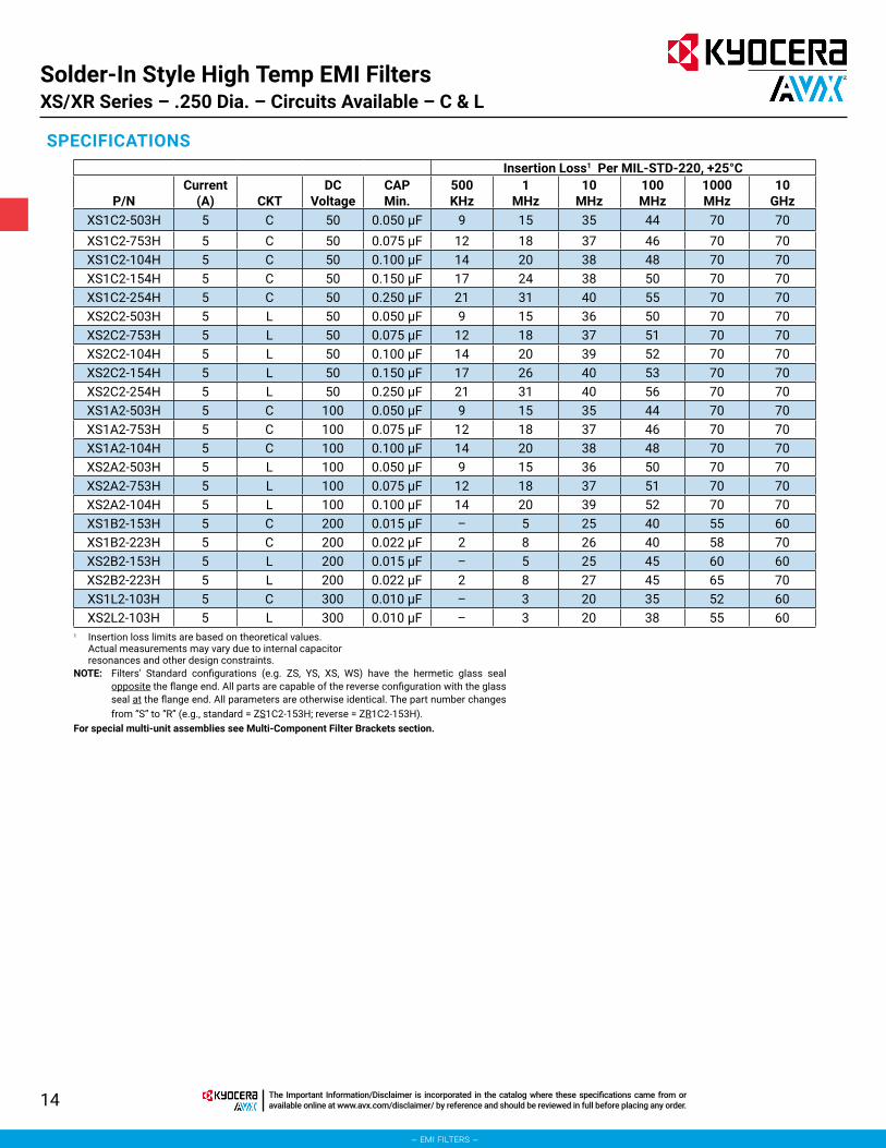
Solder-In Style High Temp EMI FiltersXS/XR Series – .250 Dia. – Circuits Available – C & L
SPECIFICATIONSInsertion Loss1 Per MIL-STD-220, +25°C
P/NCurrent
(A) CKTDC
VoltageCAPMin.
500KHz
1MHz
10MHz
100MHz
1000MHz
10GHz
XS1C2-503H 5 C 50 0.050 μF 9 15 35 44 70 70XS1C2-753H 5 C 50 0.075 μF 12 18 37 46 70 70XS1C2-104H 5 C 50 0.100 μF 14 20 38 48 70 70XS1C2-154H 5 C 50 0.150 μF 17 24 38 50 70 70XS1C2-254H 5 C 50 0.250 μF 21 31 40 55 70 70XS2C2-503H 5 L 50 0.050 μF 9 15 36 50 70 70XS2C2-753H 5 L 50 0.075 μF 12 18 37 51 70 70XS2C2-104H 5 L 50 0.100 μF 14 20 39 52 70 70XS2C2-154H 5 L 50 0.150 μF 17 26 40 53 70 70XS2C2-254H 5 L 50 0.250 μF 21 31 40 56 70 70XS1A2-503H 5 C 100 0.050 μF 9 15 35 44 70 70XS1A2-753H 5 C 100 0.075 μF 12 18 37 46 70 70XS1A2-104H 5 C 100 0.100 μF 14 20 38 48 70 70XS2A2-503H 5 L 100 0.050 μF 9 15 36 50 70 70XS2A2-753H 5 L 100 0.075 μF 12 18 37 51 70 70XS2A2-104H 5 L 100 0.100 μF 14 20 39 52 70 70XS1B2-153H 5 C 200 0.015 μF – 5 25 40 55 60XS1B2-223H 5 C 200 0.022 μF 2 8 26 40 58 70XS2B2-153H 5 L 200 0.015 μF – 5 25 45 60 60XS2B2-223H 5 L 200 0.022 μF 2 8 27 45 65 70XS1L2-103H 5 C 300 0.010 μF – 3 20 35 52 60XS2L2-103H 5 L 300 0.010 μF – 3 20 38 55 60
1 Insertion loss limits are based on theoretical values. Actual measurements may vary due to internal capacitor resonances and other design constraints.
NOTE: Filters' Standard configurations (e.g. ZS, YS, XS, WS) have the hermetic glass seal opposite the flange end. All parts are capable of the reverse configuration with the glass seal at the flange end. All parameters are otherwise identical. The part number changes from “S” to “R” (e.g., standard = ZS1C2-153H; reverse = ZR1C2-153H).
For special multi-unit assemblies see Multi-Component Filter Brackets section.

15The Important Information/Disclaimer is incorporated in the catalog where these specifications came from or available online at www.avx.com/disclaimer/ by reference and should be reviewed in full before placing any order.
– emi filters –
Solder-In Style High Temp EMI FiltersWS/WR Series – .400 Dia. – Circuits Available – C & L
The WS series expands greatly upon the XS and YS offerings by providing increased filtering in the HF through MICROWAVE frequency spectrum from 500 KHz up to 10 GHz. The larger diameter of the WS series means even higher values of capacitance, a rated DC current of 15 Amps, plus 125 VAC/400 Hz ratings are available. Designed to be soldered into a package, bracket or bulkhead (and maintain hermeticity), it is ideal for low to medium impedance circuits where large amounts
of capacitance to ground can be tolerated. In the “L” section version an internal ferrite bead element provides both inductance and series resistance (lossy characteristic) which improves insertion loss and provides superior transient performance.Alternate lead lengths or special capacitance values may be ordered.Custom packages or bracket assemblies utilizing this feedthru can be furnished to your specifications.
APPLICATIONS
CHARACTERISTICS
SPECIFICATIONS
• Meets or exceeds the applicable portions of MIL-F-28861/13. See QPL listings.
• High temperature construction withstands 300°C installation temperatures.
• Features rugged monolithic discoidal capacitor construction.
• Glass hermetic seal on one end with epoxy seal on the opposite end.
• High purity gold plating provides excellent solderability or compatibility with thermal and ultrasonic wire bonding.
1. Plating: Gold standard – Silver available2. Material:
Case: Cold rolled steel Leads: Alloy 52 steel
3. Operating Temperature Range: -55°C to +125°C
4. Insulation Resistance:At 25°C: 1,000 megohm-microfarad min.,
or 100,000 megohms min., whichever is less
At 125°C: 100 megohm-microfarad min., or 10,000 megohms min., whichever is less
5. Dielectric Withstanding Voltage (DWV): R-level designs:
2.0 times rated DC voltageClass B, Class S designs:
2.5 times rated DC voltage
6. DC Resistance (DCR): .01 ohm, maximum7. Dissipation Factor (DF): 3% maximum8. Rated DC Current: 15 Amps, maximum9. Maximum Installation Temperature: 300°C10. Supplied with 60/40 solder preform for
easy installation11. Insertion Loss for the “C” and “L” circuits
are equivalent due to the saturation characteristic of the ferrite bead element at full rated current. At lower currents the “L” becomes much more effective.
millimeters (inches)
(See Note 4) MIL-F-28861/14 (See Note 2)
Notes:1. Outline drawing shows
standard WS configuration. Also available with glass seal at the opposite end, WR reverse configuration.
2. MIL-F-28861/13 configuration “A” is equivalent to standard WS configuration. “B” is reverse WR configuration.
0.05 (.002) 6.35 (.250)0.13 (.005) 7.62 (.300)0.64 (.025) 10.16 (.400)0.8 (.03) 11.43 (.450)
1.27 (.050) 17.78 (.700)5.08 (.200) 20.32 (.800)
Circuit Diagram
DimensionsA
±.005B
Ref.L .300 .800C .200 .700
Dash No. Config.001 through 008 A009 through 016 B
3. For WS2 or WR2 L-Section Filters inductor always positioned at epoxy-filled end.
4. Metric equivalent dimensions given for information only.
C
WS1, WR1
CIRCUIT DIAGRAMS
STANDARD CONFIGURATION
WS2, WR2 (See Note 3)
GLASSSEALEND
FLANGEEND

16 The Important Information/Disclaimer is incorporated in the catalog where these specifications came from or available online at www.avx.com/disclaimer/ by reference and should be reviewed in full before placing any order.
– emi filters –
Solder-In Style High Temp EMI FiltersWS/WR Series – .400 Dia. – Circuits Available – C & L
SPECIFICATIONSInsertion Loss1 Per MIL-STD-220, +25°C
P/NCurrent
(A) CKTDC
VoltageCAPMin.
500KHz
1MHz
10MHz
100MHz
1000MHz
10GHz
WS1C2-154H 15 C 50 0.150 μF 17 24 38 50 70 70WS1C2-504H 15 C 50 0.500 μF 26 34 42 58 70 70WS1C2-754H 15 C 50 0.750 μF 31 37 43 62 70 70WS1C2-125H 15 C 50 1.200 μF 33 37 52 70 70 70WS2C2-154H 15 L 50 0.150 μF 17 26 40 53 70 70WS2C2-504H 15 L 50 0.500 μF 26 36 44 60 70 70WS2C2-754H 15 L 50 0.750 μF 31 40 44 64 70 70WS2C2-125H 15 L 50 1.200 μF 33 38 53 70 70 70WS1N2-704H 15 C 70 0.700 μF 30 36 41 60 70 70WS2N2-704H 15 L 70 0.700 μF 30 38 42 62 70 70WS1A2-154H 15 C 100 0.150 μF 17 24 38 50 70 70WS1A2-504H 15 C 100 0.500 μF 26 34 42 58 70 70WS1A2-754H 15 C 100 0.750 μF 31 37 43 62 70 70WS1A2-105H 15 C 100 1.000 μF 31 40 48 64 70 70WS2A2-154H 15 L 100 0.150 μF 17 26 40 53 70 70WS2A2-504H 15 L 100 0.500 μF 26 34 44 60 70 70WS2A2-754H 15 L 100 0.750 μF 31 40 44 64 70 70WS2A2-105H 15 L 100 1.000 μF 31 41 50 65 70 70WS1L2-503H 15 C 200* 0.050 μF 7 15 34 42 70 70WS1L2-154H 15 C 200* 0.150 μF 17 24 38 50 70 70WS2L2-503H 15 L 200* 0.050 μF 7 15 34 44 70 70WS2L2-154H 15 L 200* 0.150 μF 17 26 40 53 70 70WS1E2-103H 15 C 400 0.010 μF – 4 20 34 50 60WS1E2-503H 15 C 400 0.050 μF 7 15 34 44 70 70WS2E2-103H 15 L 400 0.010 μF – 4 20 35 55 60WS2E2-503H 15 L 400 0.050 μF 7 15 34 44 70 70
1 Insertion loss limits are based on theoretical values. Actual measurements may vary due to internal capacitor resonances and other design constraints.
NOTE: Filters' Standard configurations (e.g. ZS, YS, XS, WS) have the hermetic glass seal opposite the flange end. All parts are capable of the reverse configuration with the glass seal at the flange end. All parameters are otherwise identical. The part number changes from “S” to “R” (e.g., standard = ZS1C2-153H; reverse = ZR1C2-153H).
For special multi-unit assemblies see Multi-Component Filter Brackets section.
* Rated 200 VDC or 125 VAC/400 Hz.

17
– emi filters –
The Important Information/Disclaimer is incorporated in the catalog where these specifications came from or available online at www.avx.com/disclaimer/ by reference and should be reviewed in full before placing any order.
Bolt Style EMI FiltersSA Series – 4-40 Thread - Epoxy
Sealed – Circuits Available – C & L
18 The Important Information/Disclaimer is incorporated in the catalog where these specifications came from or available online at www.avx.com/disclaimer/ by reference and should be reviewed in full before placing any order.
– emi filters –
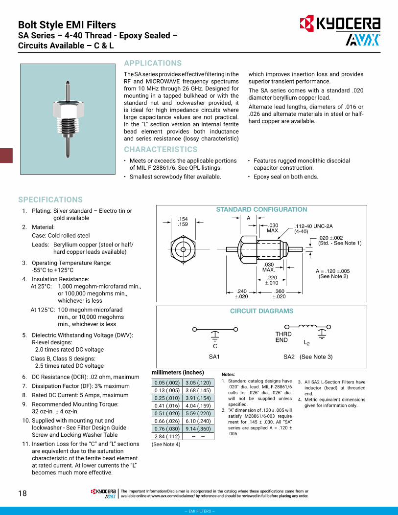
Bolt Style EMI FiltersSA Series – 4-40 Thread - Epoxy Sealed – Circuits Available – C & L
The SA series provides effective filtering in the RF and MICROWAVE frequency spectrums from 10 MHz through 26 GHz. Designed for mounting in a tapped bulkhead or with the standard nut and lockwasher provided, it is ideal for high impedance circuits where large capacitance values are not practical. In the “L” section version an internal ferrite bead element provides both inductance and series resistance (lossy characteristic)
which improves insertion loss and provides superior transient performance.The SA series comes with a standard .020 diameter beryllium copper lead.Alternate lead lengths, diameters of .016 or .026 and alternate materials in steel or half-hard copper are available.
APPLICATIONS
CHARACTERISTICS
SPECIFICATIONS
• Meets or exceeds the applicable portions of MIL-F-28861/6. See QPL listings.
• Smallest screwbody filter available.
• Features rugged monolithic discoidal capacitor construction.
• Epoxy seal on both ends.
1. Plating: Silver standard – Electro-tin or gold available
2. Material:Case: Cold rolled steelLeads: Beryllium copper (steel or half/
hard copper leads available)
3. Operating Temperature Range: -55°C to +125°C
4. Insulation Resistance:At 25°C: 1,000 megohm-microfarad min.,
or 100,000 megohms min., whichever is less
At 125°C: 100 megohm-microfarad min., or 10,000 megohms min., whichever is less
5. Dielectric Withstanding Voltage (DWV): R-level designs:
2.0 times rated DC voltageClass B, Class S designs:
2.5 times rated DC voltage
6. DC Resistance (DCR): .02 ohm, maximum7. Dissipation Factor (DF): 3% maximum8. Rated DC Current: 5 Amps, maximum9. Recommended Mounting Torque:
32 oz-in. ± 4 oz-in.10. Supplied with mounting nut and
lockwasher - See Filter Design Guide Screw and Locking Washer Table
11. Insertion Loss for the “C” and “L” sections are equivalent due to the saturation characteristic of the ferrite bead element at rated current. At lower currents the “L” becomes much more effective.
millimeters (inches)
(See Note 4)
Notes:1. Standard catalog designs have
.020" dia. lead. MIL-F-28861/6 calls for .026" dia. .026" dia. will not be supplied unless specified.
2. “A” dimension of .120 ± .005 will satisfy M28861/6-003 require ment for .145 ± .030. All “SA” series are supplied A = .120 ± .005.
0.05 (.002) 3.05 (.120)0.13 (.005) 3.68 (.145)0.25 (.010) 3.91 (.154)0.41 (.016) 4.04 (.159)0.51 (.020) 5.59 (.220)0.66 (.026) 6.10 (.240)0.76 (.030) 9.14 (.360)2.84 (.112) — —
3. All SA2 L-Section Filters have inductor (bead) at threaded end.
4. Metric equivalent dimensions given for information only.
.030MAX.
.220±.010
.360±.020
.030MAX.
A
A = .120 ±.005(See Note 2)
.240±.020
.112-40 UNC-2A(4-40)
.154
.159
.020 ±.002(Std. - See Note 1)
C
SA1
CIRCUIT DIAGRAMS
STANDARD CONFIGURATION
SA2 (See Note 3)
THRDEND L2

19The Important Information/Disclaimer is incorporated in the catalog where these specifications came from or available online at www.avx.com/disclaimer/ by reference and should be reviewed in full before placing any order.
– emi filters –
Bolt Style EMI FiltersSA Series – 4-40 Thread - Epoxy Sealed – Circuits Available – C & L
SPECIFICATIONSInsertion Loss1 Per MIL-STD-220, +25°C
P/N CKT CAPDC
VoltageDCR (Ω)
1MHz
10MHz
100MHz
200MHz
1GHz
10GHz
SA1C1-102 C 1000 pF 50 0.020 – 4 20 25 25 55SA1C1-502 C 5000 pF 50 0.020 – 15 34 41 42 55SA1C1-103 C 0.010 μF 50 0.020 4 21 35 42 50 70SA1C1-273 C 0.027 μF 50 0.020 10 30 39 43 65 70SA1C1-503 C 0.050 μF 50 0.020 15 35 42 45 70 70SA2C1-102 L2 1000 pF 50 0.020 – 4 20 27 30 60SA2C1-502 L2 5000 pF 50 0.020 – 15 35 41 45 60SA2C1-103 L2 0.010 μF 50 0.020 4 21 35 44 50 70SA2C1-273 L2 0.027 μF 50 0.020 10 30 50 45 65 70SA2C1-503 L2 0.050 μF 50 0.020 15 37 45 45 70 70SA1A1-102 C 1000 pF 100 0.020 – 4 20 25 25 55SA1A1-502 C 5000 pF 100 0.020 – 15 35 41 42 55SA1A1-103 C 0.010 μF 100 0.020 4 21 35 42 50 70SA1A1-273 C 0.027 μF 100 0.020 10 30 39 43 65 70SA1A1-453 C 0.045 μF 100 0.020 14 35 42 45 70 70SA2A1-102 L2 1000 pF 100 0.020 – 4 20 27 30 60SA2A1-502 L2 5000 pF 100 0.020 – 15 35 41 45 60SA2A1-103 L2 0.010 μF 100 0.020 4 21 35 44 50 70SA2A1-273 L2 0.027 μF 100 0.020 10 30 50 45 70 70SA2A1-453 L2 0.045 μF 100 0.020 14 37 45 45 70 70SA1B1-102 C 1000 pF 200 0.020 – 4 20 25 25 55SA1B1-502 C 5000 pF 200 0.020 – 15 34 41 42 55SA1B1-103 C 0.010 μF 200 0.020 4 21 35 42 50 70SA2B1-102 L2 1000 pF 200 0.020 – 4 20 27 30 60SA2B1-502 L2 5000 pF 200 0.020 – 15 35 41 45 60SA2B1-103 L2 0.010 μF 200 0.020 4 21 35 44 50 70
1 Insertion loss limits are based on theoretical values. Actual measurements may vary due to internal capacitor resonances and other design constraints.

20 The Important Information/Disclaimer is incorporated in the catalog where these specifications came from or available online at www.avx.com/disclaimer/ by reference and should be reviewed in full before placing any order.
– emi filters –
Bolt Style EMI FiltersSB Series – 8-32 Thread - Epoxy Sealed –Circuits Available – C, L, π
The SB series provides improved filtering in the HF through MICROWAVE frequency spectrums from 1 MHz through 10 GHz. Also designed for mounting in a tapped bulkhead or with the standard nut and lockwasher provided, it is ideal for medium to high impedance circuits where large
capacitance values are not practical. In the “L” and “π” section versions an internal ferrite bead element provides both inductance and series resistance (lossy characteristic) which improves the insertion loss rolloff to 40 dB and 60 dB per decade respectively.
APPLICATIONS
CHARACTERISTICS
SPECIFICATIONS
• Designed to meet or exceed the applicable portions of MIL-F-28861/7. See QPL listings.
• π design offers steeper insertion loss rolloff.
• Features rugged monolithic discoidal capacitor construction.
• Epoxy seal on both ends.
1. Plating: Silver standard – Electro-tin or gold available
2. Material:Case: Cold rolled steelLeads: Half/hard copper
3. Operating Temperature Range: -55°C to +125°C
4. Insulation Resistance:At 25°C: 1,000 megohm-microfarad min.,
or 100,000 megohms min., whichever is less
At 125°C: 100 megohm-microfarad min., or 10,000 megohms min., whichever is less
5. Dielectric Withstanding Voltage (DWV): R-level designs:
2.0 times rated DC voltageClass B, Class S designs:
2.5 times rated DC voltage
6. DC Resistance (DCR): .01 ohm, maximum
7. Dissipation Factor (DF): 3% maximum8. Rated DC Current: 10 Amps, maximum9. Recommended Mounting Torque:
64 oz-in. ± 4 oz-in.10. Supplied with mounting nut and
lockwasher - See Filter Design Guide Screw and Locking Washer Table
11. Insertion Loss for the “C”, “L” and “π” circuits are equivalent due to the saturation characteristic of the ferrite bead element at full rated current. At lower currents the “L” and “π” become much more effective.
millimeters (inches)
(See Note 4)
Notes:1. Nailhead standard, straight lead
available.2. Lead diameters other than
.032" available.
0.05 (.002) 1.14 (.045)0.13 (.005) 1.27 (.050)0.18 (.007) 1.85 (.073)0.25 (.010) 2.36 (.093)0.33 (.013) 4.17 (.164)0.38 (.015) 4.75 (.187)0.51 (.020) 5.49 (.216)0.64 (.025) 6.35 (.250)
0.76 (.030) 7.11 (.280)0.79 (.031) 7.92 (.312)0.81 (.032) 22.61 (.890)1.02 (.040) — —
3. All SB2 L-Section Filters have inductor (bead) at threaded end.
4. Metric equivalent dimensions given for information only.
.050±.005
.020±.005
.216±.005
.890±.013
.040MAX.
.093±.010
.312±.031
.164-32 UNC-2A(8-32)
.187±.010
.032 ±.002(Std. - See Note 2)
(Std. - See Note 1)
.045±.005
C
SB1
CIRCUIT DIAGRAMS
STANDARD CONFIGURATION
Pi
SB3SB2 (See Note 3)
THRDEND L2

21The Important Information/Disclaimer is incorporated in the catalog where these specifications came from or available online at www.avx.com/disclaimer/ by reference and should be reviewed in full before placing any order.
– emi filters –
Bolt Style EMI FiltersSB Series – 8-32 Thread - Epoxy Sealed –Circuits Available – C, L, π
SPECIFICATIONSInsertion Loss1 Per MIL-STD-220, +25°C
P/N CKT CAPDC
VoltageDCR (Ω)
1MHz
10MHz
100MHz
200MHz
1GHz
10GHz
SB1C1-102 C 1000 pF 50 0.010 – 4 20 25 40 50SB1C1-502 C 5000 pF 50 0.010 – 15 34 41 50 55SB1C1-103 C 0.010 μF 50 0.010 4 21 35 40 55 60SB1C1-273 C 0.027 μF 50 0.010 10 30 39 45 65 70SB1C1-503 C 0.050 μF 50 0.010 15 35 42 50 70 70SB2C1-273 L2 0.027 μF 50 0.010 10 30 50 54 65 70SB2C1-503 L2 0.050 μF 50 0.010 15 36 54 60 70 70SB3C1-323 π 0.032 μF 50 0.010 12 30 60 70 70 70SB1A1-102 C 1000 pF 100 0.010 – 4 20 25 40 50SB1A1-502 C 5000 pF 100 0.010 – 15 34 41 50 55SB1A1-103 C 0.010 μF 100 0.010 4 21 35 40 55 60SB1A1-273 C 0.027 μF 100 0.010 10 30 39 45 65 70SB1A1-503 C 0.050 μF 100 0.010 15 35 42 50 70 70SB2A1-103 L2 0.010 μF 100 0.010 4 21 35 38 65 70SB2A1-273 L2 0.027 μF 100 0.010 10 30 50 54 70 70SB3A1-152 π 1500 pF 100 0.010 – 8 20 45 70 70SB3A1-123 π 0.012 μF 100 0.010 – 12 60 70 70 70SB3A1-153 π 0.015 μF 100 0.010 – 17 37 43 70 70SB1B1-102 C 1000 pF 200 0.010 – 4 20 25 40 50SB1B1-502 C 5000 pF 200 0.010 – 15 34 41 50 55SB2B1-102 L2 1000 pF 200 0.010 – 4 20 27 45 70SB2B1-502 L2 5000 pF 200 0.010 – 15 35 41 55 70SB3B1-202 π 2000 pF 200 0.010 – 8 42 58 70 70
1 Insertion loss limits are based on theoretical values. Actual measurements may vary due to internal capacitor resonances and other design constraints.

22 The Important Information/Disclaimer is incorporated in the catalog where these specifications came from or available online at www.avx.com/disclaimer/ by reference and should be reviewed in full before placing any order.
– emi filters –
Bolt Style EMI FiltersSH Series – 10-32 Thread - Epoxy Sealed –Circuits Available – C, L, π
The SH series provides intermediate filtering in the RF through MICROWAVE frequency spectrums from 100 KHz through 10 GHz. The larger hex size means that much higher values of capacitance are available in the feedthru style circuits and that a 125 VAC/400 Hz rating is available in certain values. Also designed for mounting in a tapped bulkhead or with the standard nut and lockwasher provided, it is optimum in medium to low impedance circuits where significant
amounts of capacitance to ground can be tolerated. In the “L” and “π” section versions an internal ferrite bead element provides both inductance and series resistance (lossy characteristic) which improves the insertion loss rolloff to 40 dB and 60 dB per decade respectively.Alternate lead diameters or lengths are available, both with and without a nailhead.
APPLICATIONS
CHARACTERISTICS
SPECIFICATIONS
• Equivalent to SB series π circuits and to SP series feedthru or “L” circuits.
• Conservatively rated for 125 VAC/400 Hz in certain values.
• π design offers steeper insertion loss rolloff.
• Features rugged monolithic discoidal capacitor construction.
• Epoxy seal on both ends.
1. Plating: Silver standard – Electro-tin or gold available
2. Material:Case: Cold rolled steel standard,
brass availableLeads: Half/hard copper
3. Operating Temperature Range: -55°C to +125°C
4. Insulation Resistance:At 25°C: 1,000 megohm-microfarad min.,
or 100,000 megohms min., whichever is less
At 125°C: 100 megohm-microfarad min., or 10,000 megohms min., whichever is less
5. Dielectric Withstanding Voltage (DWV): R-level designs:
2.0 times rated DC voltageClass B, Class S designs:
2.5 times rated DC voltage
6. DC Resistance (DCR): .01 ohm, maximum
7. Dissipation Factor (DF): 3% maximum8. Rated DC Current: 10 Amps, maximum9. Recommended Mounting Torque:
64 oz-in. ± 4 oz-in.10. Supplied with mounting nut and lockwasher
- See Filter Design Guide Screw and Locking Washer Table
11. Insertion Loss for the “C”, “L” and “π” circuits are equivalent due to the saturation characteristic of the ferrite bead element at full rated current. At lower currents the “L” and “π” become much more effective.
millimeters (inches)
(See Note 3)
Notes:1. Nailhead standard, straight lead
available.2. All SH2 L-Section Filters have
inductor (bead) at threaded end.
0.05 (.002) 3.56 (.140)0.10 (.004) 4.83 (.190)0.13 (.005) 5.79 (.228)0.38 (.015) 5.94 (.234)0.51 (.020) 8.33 (.328)0.79 (.031) 10.69 (.421)0.81 (.032) — —
3. Metric equivalent dimensions given for information only.
.020±.005
.234±.015
.421±.031
.035MAX.
.140±.015
.328±.031
.190-32 UNF-2A(10-32)
.228±.004
.032±.002
(Std. - See Note 1)
.045±.005
C
SH1
CIRCUIT DIAGRAMS
STANDARD CONFIGURATION
Pi
SH3SH2 (See Note 2)
THRDEND L2

23The Important Information/Disclaimer is incorporated in the catalog where these specifications came from or available online at www.avx.com/disclaimer/ by reference and should be reviewed in full before placing any order.
– emi filters –
Bolt Style EMI FiltersSH Series – 10-32 Thread - Epoxy Sealed –Circuits Available – C, L, π
SPECIFICATIONSInsertion Loss1 Per MIL-STD-220, +25°C
P/N CKT CAPDC
VoltageDCR (Ω)
1MHz
10MHz
100MHz
200MHz
1GHz
10GHz
SH1C1-124 C 0.120 μF 50 0.010 21 38 49 60 70 70SH1C1-204 C 0.200 μF 50 0.010 28 39 52 60 70 70SH2C1-124 L2 0.120 μF 50 0.010 21 38 52 70 70 70SH2C1-204 L2 0.200 μF 50 0.010 28 39 54 70 70 70SH3C1-303 π 0.030 μF 50 0.010 10 28 58 70 70 70SH1A1-503 C 0.050 μF 100 0.010 15 35 42 50 70 70SH1A1-104 C 0.100 μF 100 0.010 20 38 48 53 70 70SH2A1-503 L2 0.050 μF 100 0.010 15 36 50 60 70 70SH2A1-104 L2 0.100 μF 100 0.010 20 39 52 65 70 70SH3A1-123 π 0.012 μF 100 0.010 – 12 60 70 70 70SH1L1-102 C 1000 pF 200* 0.010 – 4 20 25 40 50SH1L1-502 C 5000 pF 200* 0.010 – 15 34 41 45 55SH1L1-103 C 0.010 μF 200* 0.010 4 21 35 38 60 65SH1L1-253 C 0.025 μF 200* 0.010 8 28 36 44 64 70SH2L1-102 L2 1000 pF 200* 0.010 – 4 20 27 45 55SH2L1-502 L2 5000 pF 200* 0.010 – 15 35 41 55 65SH2L1-103 L2 0.010 μF 200* 0.010 4 21 36 40 60 65SH3B1-202 π 2000 pF 200 0.010 – 8 42 58 70 70
1 Insertion loss limits are based on theoretical values. Actual measurements may vary due to internal capacitor resonances and other design constraints.
* Rated 200 VDC or 125 VAC/400 Hz

24 The Important Information/Disclaimer is incorporated in the catalog where these specifications came from or available online at www.avx.com/disclaimer/ by reference and should be reviewed in full before placing any order.
– emi filters –
Bolt Style EMI FiltersSP Series – 12-32 Thread - Epoxy Sealed –Circuits Available – C, L, π
The SP series provides increased filtering in the HF through MICROWAVE frequency spectrums from 100 KHz through 10 GHz. The larger hex size means that much higher values of capacitance are available and that a 125 VAC/400 Hz rating is available in certain values. Also designed for mounting in a tapped bulkhead or with the standard nut and lockwasher provided, it is optimum in medium to low impedance circuits where
significant amounts of capacitance to ground can be tolerated. In the “L” and “π” section versions an internal ferrite bead element provides both inductance and series resistance (lossy characteristic) which improves the insertion loss rolloff to 40 dB and 60 dB per decade respectively.Alternate lead diameters or lengths are available both with and without a nailhead.
APPLICATIONS
CHARACTERISTICS
SPECIFICATIONS
• Designed to meet or exceed the applicable portions of MIL-F-28861/9. See QPL listing.
• Conservatively rated for 125 VAC/400 Hz in certain values.
• π design offers steeper insertion loss rolloff.
• Features rugged monolithic discoidal capacitor construction.
• Epoxy seal on both ends.
1. Plating: Silver standard – Electro-tin or gold available
2. Material:Case: Cold rolled steel standard,
brass availableLeads: Half/hard copper
3. Operating Temperature Range: -55°C to +125°C
4. Insulation Resistance:At 25°C: 1,000 megohm-microfarad min.,
or 100,000 megohms min., whichever is less
At 125°C: 100 megohm-microfarad min., or 10,000 megohms min., whichever is less
5. Dielectric Withstanding Voltage (DWV): R-level designs:
2.0 times rated DC voltageClass B, Class S designs:
2.5 times rated DC voltage
6. DC Resistance (DCR): .01 ohm, maximum
7. Dissipation Factor (DF): 3% maximum8. Rated DC Current: 10 Amps, maximum9. Recommended Mounting Torque:
64 oz-in. ± 4 oz-in.10. Supplied with mounting nut and lockwasher
- See Filter Design Guide Screw and Locking Washer Table
11. Insertion Loss for the “C”, “L” and “π” circuits are equivalent due to the saturation characteristic of the ferrite bead element at full rated current. At lower currents the “L” and “π” become much more effective.
Notes:1. Nailhead standard, straight lead available.
2. Lead diameters other than .032" available.
3. SP2 L-Section Filters have inductor (bead) at threaded end.
4. Metric equivalent dimensions given for information only.
5. Small-hex version may be specified for selected capacitance/voltage ratings. Contact KYOCERA AVX Filters Engineering for availability.
.250
.311
.921±.020
.040MAX.
.093MAX.
.157
.343±.020
.020±.005
.216 UNEF-2A(12-32)
12-32 UNEF-2A
20 GAUGE(.032)
.250±.010
.187±.005
.032 ±.002(Std. - See Note 2)
(Std. - See Note 1)
.045
.250±.005
.157±.005
.032±.005
.311±.005
.921±.020
.343±.020
.250 DIA.±.005
(See Note 5)0.05 (.002) 2.36 (.093)0.13 (.005) 3.99 (.157)0.18 (.007) 4.75 (.187)0.25 (.010) 5.49 (.216)0.51 (.020) 6.12 (.241)0.58 (.023) 6.35 (.250)0.79 (.031) 7.90 (.311)0.81 (.032) 8.71 (.343)1.02 (.040) 9.45 (.372)1.14 (.045) 9.73 (.383)1.60 (.063) 23.39 (.921)1.85 (.073) — —
millimeters (inches)
STANDARD CONFIGURATION
(See Note 4)
ALTERNATE CONFIGURATION (SC SERIES)
C
SP1
CIRCUIT DIAGRAMS
Pi
SP3SP2 (See Note 3)
THRDEND L2

25The Important Information/Disclaimer is incorporated in the catalog where these specifications came from or available online at www.avx.com/disclaimer/ by reference and should be reviewed in full before placing any order.
– emi filters –
Bolt Style EMI FiltersSP Series – 12-32 Thread - Epoxy Sealed –Circuits Available – C, L, π
SPECIFICATIONSInsertion Loss1 Per MIL-STD-220, +25°C
P/N CKT CAPDC
VoltageDCR (Ω)
1MHz
10MHz
100MHz
200MHz
1GHz
10GHz
SP1C1-204 C 0.200 μF 50 0.010 26 39 52 60 70 70SP2C1-204 L2 0.200 μF 50 0.010 26 38 65 70 70 70SP3C1-124 π 0.120 μF 50 0.010 20 38 70 70 70 70SP1A1-503 C 0.050 μF 100 0.010 15 35 38 50 70 70SP1A1-104 C 0.100 μF 100 0.010 20 38 48 53 70 70SP2A1-503 L2 0.050 μF 100 0.010 15 36 54 60 70 70SP3A1-753 π 0.075 μF 100 0.010 18 38 70 70 70 70SP1L1-102 C 1000 pF 200* 0.010 – 4 20 25 40 50SP1L1-502 C 5000 pF 200* 0.010 – 15 34 41 50 55SP1L1-103 C 0.010 μF 200* 0.010 4 21 35 40 55 60SP1L1-253 C 0.025 μF 200* 0.010 8 28 36 44 64 70SP2L1-102 L2 1000 pF 200* 0.010 – 4 20 27 45 70SP2L1-502 L2 5000 pF 200* 0.010 – 15 35 41 55 70SP2L1-103 L2 0.010 μF 200* 0.010 4 21 35 38 65 70SP3B1-152 π 1500 pF 200 0.010 – 8 20 45 70 70SP3B1-123 π 0.012 μF 200 0.010 – 12 60 70 70 70
1 Insertion loss limits are based on theoretical values. Actual measurements may vary due to internal capacitor resonances and other design constraints.
* Rated 200 VDC or 125 VAC/400 Hz

26 The Important Information/Disclaimer is incorporated in the catalog where these specifications came from or available online at www.avx.com/disclaimer/ by reference and should be reviewed in full before placing any order.
– emi filters –
Bolt Style EMI FiltersSH Series – 10-32 Thread - Epoxy Sealed –Circuits Available – C, L, π
The SN series offers effective filtering from 1 MHz to 10 GHz. Glass sealed on both ends for hermeticity, this series is impervious to high moisture, solvents, or other severe environmental conditions commonly encountered in military applications. It is designed for bulkhead mounting with nut and lockwasher supplied.The feedthru designs yield constant filtering as current level is increased from no-load
to full rated load. They are most effective when placed in high impedance circuits. The π-section designs exhibit sharper roll-off in filter characteristic and perform effectively when used in medium to low impedance circuits.Alternate lead configurations or special capacitance values and voltage ratings may be ordered.
APPLICATIONS
CHARACTERISTICS
SPECIFICATIONS
• The hermetic bolt-style design was developed to meet or exceed the applicable portions of MIL-F-28861/10. The filter is assembled with a glass hermetic seal on both ends. The rugged monolithic capacitor element is a low inductance design that yields superior
bypass performance. The π-section design contains two capacitor elements together with a ferrite bead inductor.
• Certain feedthru designs are rated for 115 VAC/400 Hz applications. The 200 VDC π-section design is rated for DC applications only.
1. Plating: Silver standard – Electro-tin or gold available
2. Material:Case: Cold rolled steel standard, brass availableLeads: Copper nailhead standard. Only available
in .032" diameter. Beryllium copper lead available. Straight lead available.
3. Operating Temperature Range: -55°C to +125°C
4. Electrical Characteristics:A. Capacitance: Guaranteed Minimum Value
(GMV) as listedB. Insulation Resistance:
At 25°C: 1,000 megohm-microfarad min., or 100,000 megohms min., whichever is less
At 125°C: 100 megohm-microfarad min., or 10,000 megohms min., whichever is less
C. Dielectric Withstanding Voltage (DWV): R-level designs:
2.0 times rated DC voltageClass B, Class S designs:
2.5 times rated DC voltageD. DC Resistance (DCR): .01 ohm, maximumE. Voltage Drop: 0.1 volt, maximumF. Dissipation Factor (DF): 3% maximumG. Rated Current: 10 Amps, maximum
5. Seal: In accordance with MIL-F-28861. Leakage rate for Class S designs shall not exceed 1 x 10⁻⁷ atm cc/sec.
6. Marking: Standard (KYOCERA AVX symbol, AVX part number)
7. Installation: Filter is supplied with mounting nut and lockwasher. The recommended mounting torque is 64 oz-in. ± 4 oz-in. Refer to the “Installation and Handling” section for additional information.
millimeters (inches)
(See Note 1)
Notes:1. Metric equivalent dimensions
given for information only.0.05 (.002) 1.85 (.073)0.13 (.005) 3.99 (.157)0.18 (.007) 5.49 (.216)0.25 (.010) 6.12 (.241)0.51 (.020) 6.35 (.250)0.58 (.023) 7.90 (.311)0.79 (.031) 8.71 (.343)0.81 (.032) 9.45 (.372)1.02 (.040) 9.73 (.383)1.14 (.045) 23.39 (.921)1.60 (.063) — —
.250±.005.311±.005
.921±.020
.040MAX.
.220MAX.
.343±.020
.216-32 UNEF-2A(12-32)
.250±.010
.032 ±.002
C
SN1
CIRCUIT DIAGRAMS
STANDARD CONFIGURATION
Pi
SN3SN2
L2

27The Important Information/Disclaimer is incorporated in the catalog where these specifications came from or available online at www.avx.com/disclaimer/ by reference and should be reviewed in full before placing any order.
– emi filters –
Bolt Style EMI FiltersSH Series – 10-32 Thread - Epoxy Sealed –Circuits Available – C, L, π
SPECIFICATIONSInsertion Loss1 Per MIL-STD-220, +25°C
P/N CKT CAPDC
VoltageDCR (Ω)
1MHz
10MHz
100MHz
200MHz
1GHz
10GHz
SN1C1-204 C 0.200 μF 50 0.010 26 39 52 60 70 70SN2C1-204 L2 0.200 μF 50 0.010 26 38 65 70 70 70SN3C1-124 π 0.120 μF 50 0.010 20 38 70 70 70 70SN1A1-503 C 0.050 μF 100 0.010 15 35 42 50 70 70SN1A1-104 C 0.100 μF 100 0.010 20 38 48 53 70 70SN2A1-503 L2 0.050 μF 100 0.010 15 36 54 60 70 70SN3A1-753 π 0.075 μF 100 0.010 18 38 70 70 70 70SN1L1-102 C 1000 pF 200* 0.010 – 4 20 25 40 50SN1L1-502 C 5000 pF 200* 0.010 – 15 34 41 50 55SN1L1-103 C 0.010 μF 200* 0.010 4 21 35 40 55 60SN1L1-253 C 0.025 μF 200* 0.010 8 28 36 44 64 70SN2L1-102 L2 1000 pF 200* 0.010 – 4 20 27 45 70SN2L1-502 L2 5000 pF 200* 0.010 – 15 35 41 55 70SN2L1-103 L2 0.010 μF 200* 0.010 4 21 35 38 65 70SN3B1-152 π 1500 pF 200 0.010 – 8 20 45 70 70SN3B1-123 π 0.012 μF 200 0.010 – 12 60 70 70 70
1 Insertion loss limits are based on theoretical values. Actual measurements may vary due to internal capacitor resonances and other design constraints.
* Rated 200 VDC or 125 VAC/400 Hz

28
– emi filters –
The Important Information/Disclaimer is incorporated in the catalog where these specifications came from or available online at www.avx.com/disclaimer/ by reference and should be reviewed in full before placing any order.
Advanced Technology Filters
Miniature, Subminiature & Microminiature

29The Important Information/Disclaimer is incorporated in the catalog where these specifications came from or available online at www.avx.com/disclaimer/ by reference and should be reviewed in full before placing any order.
– emi filters –
Advanced Technology FiltersMiniature, Subminiature & Microminiature
APPLICATIONS KYOCERA AVX’s Miniature filter line breaks the “small” size barrier. These ultraminiature products, available as solder-in or screw-in style, have case diameters as low as .073". Threaded filters will allow substitution, flexibility of placement and simple installation, while solder-in parts will provide hermeticity of your microcircuit packages. Now, with capacitance values of up to 50,000 pF, “C”, “L” or “T” circuits, superior insertion loss over on-board filtering, variety of ultra small and lightweight sizes, you can meet all “mission critical” objectives. World’s smallest and most complete miniature EMI filter line is especially well suited for microwave industry, medical electronics, avionics instrumentation, satellites or other applications where space is at premium.
FEATURES �World’s smallest filters, a “must” for avionics and space industry. � Tiny size for miniaturization of microwave and telecom equipment. � Hardware real-estate and weight reduction of up to 60%. �Most complete product offering with solder-in or bolt installation. � Discoidal capacitor design to meet cost/reliability goals.
– LEAD – CASE – EPOXY – SOLDER – GLASS SEAL – CAPACITOR
NOTE: Torque limiting tool with custom adapter available upon request.
SPECIFICATIONSMechanicalMaterial: Solder-In: Case and Leads:
Kovar per ASTM F-15Screw-in: Case: CRS per ASTM-108
Leads: Copper clad steel(1-64 & 2-56 Thd.)Copper (4-40 & 8-36 Thd.)
Finish: Solder-in: Gold per Mil-G-45204 Screw-in: Gold per Mil-G-45204 (standard) Silver optional (1-64 & 2-56 Thd.) Silver per QQ-S-365 (standard) Gold optional (4-40 & 8-36 Thd.)
ElectricalCapacitance: measured @ 1KHz and .1 to 1 VRMS, 25°CDissipation factor: 3% max.Insulation resistance: 10,000 Mohms min. @ 25°C, WVDC;1000 Mohms min. @ 125°C, WVDCDC resistance: .02 ohm max.Dielectric withstanding voltage: 200% of WVDC min.
1
2
3
4
6
3
pe "B"

30 The Important Information/Disclaimer is incorporated in the catalog where these specifications came from or available online at www.avx.com/disclaimer/ by reference and should be reviewed in full before placing any order.
– emi filters –
EMI FiltersMiniature, Subminiature & Microminiature
SPECIFICATIONS
PartNumber
Voltage Vdc(V)
Min.Cap(pF)
CurrentIdc(A)
MINIMUM NO LOAD INSERTION LOSS (db) @ 25°C PER MIL-STD-220
10MHZ
30MHZ
100MHZ
300MHZ
1GHZ
10GHZ
.075±.002(1.90±0.05)
.093±.005(2.36±0.13)
.100±.020(2.54±0.5)
.275±.020(6.98±0.5)
.016±.002(0.41±0.05)
.075±.005(1.90±0.13)
.008±.003(0.20±0.08)
.030 (0.76)MAX. POTTING
MENISCUS
GLASSSEAL
ZXS1C3-502 50 5000 1.5 15 22 35 45 55 60ZXS1C3-272 50 2700 1.5 10 17 30 38 50 60ZXS1A3-152 100 1500 1.5 5 12 25 33 45 55ZXS1A3-102 100 1000 1.5 4 10 22 30 42 55ZXS1A3-501 100 500 1.5 - - 15 25 35 50ZXS1A3-251 100 250 1.5 - - 10 17 27 40ZXS1B3-101 200 100 1.5 - - 3 10 20 30ZXS1B3-500 200 50 1.5 - - 1 6 15 25ZXS1B3-250 200 25 1.5 - - - 1 10 22ZXS1B3-100 200 10 1.5 - - - - 3 20ZXS1B3-5R0 200 5 1.5 - - - - - 15ZXS1B3-000 200 2 max. 1.5 - - - - - -
GLASSSEAL
.105±.002(2.67±0.05)
.020±.002(0.51±0.05)
.030 (0.76)MAX. POTTING
MENISCUS
.350±.020(8.89±0.5)
.125±.005(3.18±0.13)
.125±.020(3.18±0.5)
.008±.003(0.20±0.08)
.100±.005(2.54±0.13)
ZYS1C3-273 50 27000 2.5 30 37 43 53 65 70ZYS1C3-103 50 10000 2.5 20 27 37 47 60 65ZYS1A3-502 100 5000 2.5 15 22 35 45 55 60ZYS1A3-272 100 2700 2.5 10 17 30 38 50 60ZYS1A3-152 100 1500 2.5 5 12 25 33 45 55ZYS1B3-102 200 1000 2.5 4 10 22 30 42 55ZYS1B3-501 200 500 2.5 - - 15 25 35 50ZYS1B3-251 200 250 2.5 - - 10 17 27 40ZYS1B3-101 200 100 2.5 - - 3 10 20 30ZYS1B3-500 200 50 2.5 - - 1 6 15 25ZYS1B3-250 200 25 2.5 - - - 1 10 22ZYS1B3-100 200 10 2.5 - - - - 3 20ZYS1B3-5R0 200 5 2.5 - - - - - 15ZYS1B3-000 200 2 max. 2.5 - - - - - -
GLASSSEAL
.110±.005(2.79±0.13)
.008±.003(0.20±0.08)
.030 (0.76)MAX. POTTING
MENISCUS
.400±.020(10.16±0.5)
.140±.020(3.56±0.5)
.140±.005(3.56±0.13)
.120±.002(3.05±0.05)
.030±.002(0.76±0.05)
ZZS1C3-503 50 50000 5 35 40 45 55 70 70ZZS1C3-273 50 27000 5 30 37 43 53 65 70ZZS1A3-103 100 10000 5 20 27 37 47 60 65ZZS1B3-502 200 5000 5 15 22 35 45 55 60ZZS1B3-272 200 2700 5 10 17 30 38 50 60ZZS1B3-152 200 1500 5 5 12 25 33 45 55ZZS1B3-102 200 1000 5 4 10 22 30 42 55ZZS1B3-501 200 500 5 - - 15 25 35 50ZZS1B3-251 200 250 5 - - 10 17 27 40ZZS1B3-101 200 100 5 - - 3 10 20 30ZZS1B3-500 200 50 5 - - 1 6 15 25ZZS1B3-250 200 25 5 - - - 1 10 22ZZS1B3-100 200 10 5 - - - - 3 20ZZS1B3-5R0 200 5 5 - - - - - 15ZZS1B3-000 200 2 max. 5 - - - - - -
NOTE: Dimensions in inches (millimeters).
CONFIGURATION OPTIONSGlass SealTerminals Schematic
Flattened at Glass Seal End Only
� Opposite Flange End – Standard � At Flange End – Reversed
Change 3rd letter of part number from “S” to “R” for reversed configuration
� "C" STANDARD
� GLASSSEALEND
"L1" AVAILABLEWITH EXTENDEDCASE LENGTH

31The Important Information/Disclaimer is incorporated in the catalog where these specifications came from or available online at www.avx.com/disclaimer/ by reference and should be reviewed in full before placing any order.
– emi filters –
EMI FiltersMiniature, Subminiature & Microminiature
SCREW-IN STYLE, C TYPE 48--3406 THD.
SPECIFICATIONS
PartNumber
VoltageVdc(V)
Min.Cap(pF)
CurrentIdc(A)
MINIMUM NO LOAD INSERTION LOSS (db) @ 25°C PER MIL-STD-220
10MHZ
30MHZ
100MHZ
300MHZ
1GHZ
10GHZ
.075±.005(1.91±0.13)
.225±.020(5.72±0.50)
.125±.003(3.18±0.08)
ø.032±.002(0.81±0.05)
.315±.020(8.00±0.50)
.140±.005(3.56±0.13)
#4-40UNC-2A THD.
.030 MAX.(0.762)IMPERFECT THD.
.030 MAX.(0.762)UNDERCUT
MOUNTING TORQUE: 32 ± 4 oz-in
SA1C3-503 50 50000 10 15 35 45 55 70 70SA1A3-273 100 27000 10 10 30 43 53 65 70SA1A3-103 100 10000 10 4 20 37 47 60 65SA1B3-502 200 5000 10 – 15 35 45 55 60SA1B3-272 200 2700 10 – 10 30 38 50 60SA1B3-152 200 1500 10 – 5 25 33 45 55SA1B3-102 200 1000 10 – 4 22 30 42 55SA1B3-501 200 500 10 – – 15 25 35 50SA1B3-251 200 250 10 – – 10 17 27 40SA1B3-101 200 100 10 – – 3 10 20 30SA1B3-500 200 50 10 – – 1 6 15 25SA1B3-250 200 25 10 – – – 1 10 22SA1B3-100 200 10 10 – – – – 3 20SA1B3-5R0 200 5 10 – – – – – 15
.120(3.05)
.240±.031(6.10±0.79)
.154 (3.91)
.159 (4.04)
ø.026±.002(0.66±0.05)
.360±.031(9.14±0.79)
.220±.010(5.59±0.25)
#4-40UNC-2A THD.
.030 MAX.(0.762)IMPERFECT THD.
.030 MAX.(0.762)UNDERCUT
MOUNTING TORQUE: 32 ± 4 oz-in
SA1C1-104 50 100000 10 20 40 50 60 70 70SA1A1-503 100 50000 10 15 35 45 55 70 70SA1A1-273 100 27000 10 10 30 43 53 65 70SA1B1-103 200 10000 10 4 20 37 47 60 65SA1B1-502 200 5000 10 – 15 35 45 55 60SA1B1-272 200 2700 10 – 10 30 38 50 60SA1B1-102 200 1000 10 – 4 22 30 42 55SA1B1-501 200 500 10 – – 15 25 35 50SA1B1-251 200 250 10 – – 10 17 27 40SA1B1-101 200 100 10 – – 3 10 20 30SA1B1-500 200 50 10 – – 1 6 15 25SA1B1-250 200 25 10 – – – 1 10 22SA1B1-100 200 10 10 – – – – 3 20SA1B1-5R0 200 5 10 – – – – – 15
.040±.005(1.02±0.13)
.240±.020(6.10±0.50)
.187±.010(4.75±0.25)
ø.030±.002(0.76±0.05)
.360±.020(9.14±0.50)
.025 MAX.(0.64)IMPERFECT THD.
#8-36UNF-2A THD.
.015 MAX.(0.38)UNDERCUT
.090±.010(2.29±0.25)
MOUNTING TORQUE: 64 ± 4 oz-in
SZ1C1-503 50 50000 10 15 35 45 55 70 70SZ1A1-273 100 27000 10 10 30 43 53 65 70SZ1A1-103 100 10000 10 4 20 37 47 60 65SZ1B1-502 200 5000 10 – 15 35 45 55 60SZ1B1-272 200 2700 10 – 10 30 38 50 60SZ1B1-152 200 1500 10 – 5 25 33 45 55SZ1B1-102 200 1000 10 – 4 22 30 42 55SZ1B1-501 200 500 10 – – 15 25 35 50SZ1B1-251 200 250 10 – – 10 17 27 40SZ1B1-101 200 100 10 – – 3 10 20 30SZ1B1-500 200 50 10 – – 1 6 15 25SZ1B1-250 200 25 10 – – – 1 10 22SZ1B1-100 200 10 10 – – – – 3 20SZ1B1-5R0 200 5 10 – – – – – 15
NOTE: Dimensions in inches (millimeters).
CONFIGURATION OPTIONSLeads Schematic
� Custom lead lengths and materials available
� Chamfered or rounded lead tips for mating with connectors

32 The Important Information/Disclaimer is incorporated in the catalog where these specifications came from or available online at www.avx.com/disclaimer/ by reference and should be reviewed in full before placing any order.
– emi filters –
EMI FiltersMiniature, Subminiature & Microminiature
SCREW-IN STYLE, C TYPE 1-642-56 THD.
SPECIFICATIONS
PartNumber
VoltageVdc(V)
Min.Cap(pF)
CurrentIdc(A)
MINIMUM NO LOAD INSERTION LOSS (db) @ 25°C PER MIL-STD-220
10MHZ
30MHZ
100MHZ
300MHZ
1GHZ
10GHZ
MOUNTING TORQUE: 7 ± 1 oz-in
.080±.005(2.03±0.13)
.018±.002(0.46±0.05)
.021±.001(0.53±0.03)
.073±.003(1.85±0.08)
.020±.003(0.51±0.08)
.180±.020(4.57±0.5)
.090±.005(2.29±0.13)
.190±.020(4.83±0.5)
#1-64UNC-2A THD.
1.5 MAX. IMPERFECT THD.NO UNDERCUT
SXD1C3-502 50 5000 3 15 22 35 45 55 60SXD1C3-272 50 2700 3 10 17 30 38 50 60SXD1A3-152 100 1500 3 5 12 25 33 45 55SXD1A3-102 100 1000 3 4 10 22 30 42 55SXD1A3-501 100 500 3 – – 15 25 35 50SXD1A3-251 100 250 3 – – 10 17 27 40SXD1B3-101 200 100 3 – – 3 10 20 30SXD1B3-500 200 50 3 – – 1 6 15 25SXD1B3-250 200 25 3 – – – 1 10 22SXD1B3-100 200 10 3 – – – – 3 20SXD1B3-5R0 200 5 3 – – – – – 15
MOUNTING TORQUE: 14 ± 2 oz-in
.021±.001(0.53±0.03)
.018±.002(0.46±0.05)
.086±.003(2.18±0.08)
.020±.003(0.51±0.08)
.180±.020(4.57±0.5)
.080±.005(2.03±0.13)
1.5 MAX. IMPERFECT THD.NO UNDERCUT
.190±.020(4.83±0.5)
.090±.005(2.29±0.13)
#2-56UNC-2A THD.
SYD1C3-502 50 5000 3 15 22 35 45 55 60SYD1C3-272 50 2700 3 10 17 30 38 50 60SYD1A3-152 100 1500 3 5 12 25 33 45 55SYD1A3-102 100 1000 3 4 10 22 30 42 55SYD1A3-501 100 500 3 – – 15 25 35 50SYD1A3-251 100 250 3 – – 10 17 27 40SYD1B3-101 200 100 3 – – 3 10 20 30SYD1B3-500 200 50 3 – – 1 6 15 25SYD1B3-250 200 25 3 – – – 1 10 22SYD1B3-100 200 10 3 – – – – 3 20SYD1B3-5R0 200 5 3 – – – – – 15
MOUNTING TORQUE: 14 ± 2 oz-in
.110±.005(2.79±0.13)
1.5 MAX. IMPERFECT THD.NO UNDERCUT
#2-56UNC-2A THD.
.090±.005(2.29±0.13)
.240±.020(6.10±0.5)
.260±.020(6.60±0.5)
.020±.003(0.51±0.08)
.024±.002(0.61±0.05)
.105±.005(2.67±0.13)
.021±.001(.53±0.03)
SZD1C3-273 50 27000 5 30 37 43 53 65 70SZD1C3-103 50 10000 5 20 27 37 47 60 65SZD1A3-502 100 5000 5 15 22 35 45 55 60SZD1A3-272 100 2700 5 10 17 30 38 50 60SZD1A3-152 100 1500 5 5 12 25 33 45 55SZD1B3-102 200 1000 5 4 10 22 30 42 55SZD1B3-501 200 500 5 – – 15 25 35 50SZD1B3-251 200 250 5 – – 10 17 27 40SZD1B3-101 200 100 5 – – 3 10 20 30SZD1B3-500 200 50 5 – – 1 6 15 25SZD1B3-250 200 25 5 – – – 1 10 22SZD1B3-100 200 10 5 – – – – 3 20SZD1B3-5R0 200 5 5 – – – – – 15
NOTE: Dimensions in inches (millimeters). Torque limiting tool with custom adapter required for proper installation (see page 2)
CONFIGURATION OPTIONSMountingTerminals Schematic
“SZD” and “SYD” Parts Only Slotted terminal available
on one or both sides
� .090 Thd. Length Standard, intended for tapped holefeed through mounting
� .140 Thd. Length available for through hole mounting with hex nut
"C" STANDARD
"T"
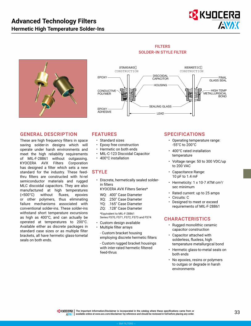
33The Important Information/Disclaimer is incorporated in the catalog where these specifications came from or available online at www.avx.com/disclaimer/ by reference and should be reviewed in full before placing any order.
– emi filters –
Advanced Technology FiltersHermetic High Temperature Solder-Ins
CONSTRUCTION CONSTRUCTIONDISCOIDALCAPACITOR
HOUSING
SEALING GLASS
LEAD
EPOXY
CONDUCTIVEPOLYMER
EPOXYADHESIVE
FINALGLASS SEAL
HIGH TEMPMETALLURGICAL
BOND
FILTERSSOLDER-IN STYLE FILTER
GENERAL DESCRIPTION These are high frequency filters in space saving solder-in designs which will operate under harsh environments and meet the high reliability requirements of MIL-F-28861 without outgassing. KYOCERA AVX Filters Corporation has designed a filter which sets a new standard for the industry. These feed-thru filters are constructed with hi-rel semiconductor materials and rugged MLC discoidal capacitors. They are also manufactured at high temperatures (>500°C) without fluxes, epoxies or other polymers, thus eliminating failure mechanisms associated with conventional solder-ins. These solder-ins withstand short temperature excursions as high as 400°C, and can actually be operated at temperatures to 200°C. Available either as discrete packages in standard case sizes or as multiple filter brackets, all have hermetic glass-tometal seals on both ends.
FEATURES • Standard sizes• Epoxy free construction• Hermetic on both ends• MIL-C-123 Discoidal Capacitor• 400°C installation
STYLE• Discrete, hermetically sealed solder-
in filtersKYOCERA AVX Filters Series*WQ: .400" Case DiameterXQ: .250" Case DiameterYQ: .165" Case DiameterZQ: .128" Case Diameter*Equivalent to MIL-F-28861 Series FS70, FS71, FS72, FS73 and FS74
• Custom design available• Multiple filter arrays
- Custom bracket housing employing discrete hermetic filters- Custom rugged bracket housings with inter-rated hermetic filtered feed-thrus
SPECIFICATIONS• Operating temperature range:
-55°C to 200°C• 400°C rated installation
temperature• Voltage range: 50 to 300 VDC/up
to 200 VAC• Capacitance Range:
10 pF to 1.4 mF• Hermeticity: 1 x 10⁻⁷ ATM cm3/
sec minimum• Rated current: up to 25 amps• Circuits: C• Designed to meet or exceed
requirements of MIL-F-28861
CHARACTERISTICS• Rugged monolithic ceramic
capacitor construction• Capacitor attached with
solderless, fluxless, high temperature metallurgical bond
• Hermetic glass-to-metal seals on both ends
• No epoxies, resins or polymers to outgas or degrade in harsh environments

34
– emi filters –
The Important Information/Disclaimer is incorporated in the catalog where these specifications came from or available online at www.avx.com/disclaimer/ by reference and should be reviewed in full before placing any order.
Cylindrical Style EMI Filters
BL Series – .375 Dia. – Button Epoxy Sealed – Circuits
Available – C & L

35The Important Information/Disclaimer is incorporated in the catalog where these specifications came from or available online at www.avx.com/disclaimer/ by reference and should be reviewed in full before placing any order.
– emi filters –
Cylindrical Style EMI FiltersBL Series – .375 Dia. – Button Epoxy Sealed – Circuits Available – C & L
The BL series offers effective filtering from 30 KHz up through 1 GHz. It offers epoxy resin seals on both ends in order to optimize volumetric efficiency and reduce cost. Where severe moisture environments exist the slightly larger companion BK series is recommended as it incorporates a glass to metal hermetic seal at both ends. The BL series is designed for bulkhead mounting in a slotted hole with nut and lockwasher supplied. This series is ideal for low to medium impedance circuits where large amounts of capacitance to ground can
be tolerated. In the “L” section version an internal ferrite bead element provides both inductance and series resistance (lossy characteristic) which improves insertion loss at lower current ratings and provides superior transient performance.Alternate lead configurations or special capacitance values may be ordered.Custom packages or filter arrays utilizing the BL series can be furnished.
APPLICATIONS
CHARACTERISTICS
SPECIFICATIONS
• Internal ferrite bead provides inductance for the L-section version.
• High DC current rating: 15 Amps.
1. Case/Terminal Plating: Electro-tin standard – Gold or silver available
2. Material:Case: Brass Standard – Steel availableEnd Seal: EpoxyTerminals: Copper nailhead standard
3. Operating Temperature Range: -55°C to +125°C
4. Electrical Characteristics:A. Rated Voltage: See chartB. Insulation Resistance:
At 25°C: 1,000 megohm-microfarad min., or 100,000 megohms min., whichever is less
At 125°C: 100 megohm-microfarad min., or 10,000 megohms min., whichever is less
C. Dielectric Withstanding Voltage (DWV): R-level designs:
2.0 times rated DC voltageClass B designs:
2.5 times rated DC voltageD. Capacitance: Values listed in chart are
“guaranteed minimum value” (GMV)5. Marking:
Standard Marking: KYOCERA AVX, KYOCERA AVX part number, lot codeBL2 only: Letter “L” denotes ferrite bead inductor at threaded endSee Reliability Codes section for definition of Reliability Level marking. See How to Order section for part number construction.
6. Installation:A. Mounting Torque:
44 oz-in. ± 4 oz-in.B. Refer to “Installation, Handling, Hardware
Options” section of the catalog.
millimeters (inches)
(See Note 2)
Notes:1. All BL2 L-Section Filters have
inductor (bead) at threaded end.
.25 (.010) 2.54 (.100)
.76 (.030) 3.81 (.150)
.81 (.032) 4.57 (.180)1.02 (.040) 5.08 (.200)1.52 (.060) 9.53 (.375)
2. Metric equivalent dimensions given for information only.
250-28 UNF-2A (1/4-28)
.050
.200±.010
.040±.010
.150±.032
*±.010
.280±.032
.030±.010
.150MAX.
.060REF.
.375±.010
* = A FOR .187 ±.010 THREAD B FOR .312 THREAD
(See Note 1)
CIRCUIT DIAGRAMS
STANDARD CONFIGURATION
BL2 (See Note 1)
THRDEND L2C
BL1
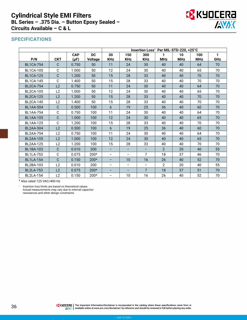
36 The Important Information/Disclaimer is incorporated in the catalog where these specifications came from or available online at www.avx.com/disclaimer/ by reference and should be reviewed in full before placing any order.
– emi filters –
Cylindrical Style EMI FiltersBL Series – .375 Dia. – Button Epoxy Sealed – Circuits Available – C & L
SPECIFICATIONS
Insertion Loss1 Per MIL-STD-220, +25°C
P/N CKTCAP (μF)
DCVoltage
30KHz
150KHz
300KHz
1MHz
10MHz
100MHz
1GHz
BL1CA-754 C 0.750 50 11 24 30 40 40 64 70BL1CA-105 C 1.000 50 12 24 30 40 40 65 70BL1CA-125 C 1.200 50 15 28 33 40 40 70 70BL1CA-145 C 1.400 50 15 28 33 40 40 70 70BL2CA-754 L2 0.750 50 11 24 30 40 40 64 70BL2CA-105 L2 1.000 50 12 24 30 40 40 65 70BL2CA-125 L2 1.200 50 15 28 33 40 40 70 70BL2CA-145 L2 1.400 50 15 28 33 40 40 70 70BL1AA-504 C 0.500 100 6 19 25 36 40 60 70BL1AA-754 C 0.750 100 11 24 30 40 40 64 70BL1AA-105 C 1.000 100 12 24 30 40 40 65 70BL1AA-125 C 1.200 100 15 28 33 40 40 70 70BL2AA-504 L2 0.500 100 6 19 25 36 40 60 70BL2AA-754 L2 0.750 100 11 24 30 40 40 64 70BL2AA-105 L2 1.000 100 12 24 30 40 40 65 70BL2AA-125 L2 1.200 100 15 28 33 40 40 70 70BL1BA-103 C 0.010 200 – – – 2 20 40 55BL1LA-753 C 0.075 200* – – 7 18 37 46 70BL1LA-154 C 0.150 200* – 10 16 26 40 52 70BL2BA-103 L2 0.010 200 – – – 2 20 40 55BL2LA-753 L2 0.075 200* – – 7 18 37 51 70BL2LA-154 L2 0.150 200* – 10 16 26 40 52 70
1 Insertion loss limits are based on theoretical values. Actual measurements may vary due to internal capacitor resonances and other design constraints.
* Also rated 125 VAC/400 Hz

37The Important Information/Disclaimer is incorporated in the catalog where these specifications came from or available online at www.avx.com/disclaimer/ by reference and should be reviewed in full before placing any order.
– emi filters –
Cylindrical Style EMI FiltersBK Series – .375/.410 Dia. – Button Hermetically Sealed Circuits Available – C & L
The BK series offers effective filtering from 500 KHz to 10 GHz. Glass sealed for hermeticity, this low profile series is impervious to high moisture, solvents, or other severe environmental conditions commonly encountered in military applications. It is designed for bulkhead mounting in a slotted hole with nut and lockwasher supplied. This series is ideal for low to medium impedance circuits where large amounts of capacitance to ground can be tolerated. In the “L” section version an internal ferrite
bead element provides both inductance and series resistance (lossy characteristic) which improves insertion loss and provides superior transient performance.Alternate lead configurations or special capacitance values may be ordered.Custom packages or filter arrays utilizing the BK series can be furnished.
APPLICATIONS
CHARACTERISTICS
SPECIFICATIONS
• .410 Dia. version (AK) meets or exceeds the applicable requirements of MIL-F-28861/1. See QPL listings.
• Glass hermetic seal on both ends.
• Internal ferrite bead provides inductance for the L-section version.
• High DC current rating: 15 Amps
1. Case/Terminal Plating: Electro-tin standard – Silver or gold available
2. Material:Case: Brass Standard – Steel availableEnd Seal: Mild steelTerminals: Nickel-iron alloy
3. Operating Temperature Range: -55°C to +125°C
4. Electrical Characteristics:A. Rated Voltage: See chartB. Insulation Resistance:
At 25°C: 1,000 megohm-microfarad min., or 100,000 megohms min., whichever is less
At 125°C: 100 megohm-microfarad min., or 10,000 megohms min., whichever is less
C. Dielectric Withstanding Voltage (DWV): R-level designs:
2.0 times rated DC voltageClass B, Class S designs:
2.5 times rated DC voltageD. Capacitance: Values listed in chart are
“guaranteed minimum value” (GMV)5. Marking:
Standard Marking: KYOCERA AVX, KYOCERA AVX part number, lot codeBK2 only: Letter “L” denotes ferrite bead inductor at threaded endSee Reliability Codes section for definition of Reliability Level marking. See How to Order section for part number construction.
6. Installation:A. Mounting Torque:
44 oz-in. ± 4 oz-in.B. Refer to “Installation, Handling, Hardware
Options” section of the catalog.
millimeters (inches)
(See Note 3)(See Note 1)
Notes:1. Thread length option. Standard
part numbers shown (e.g., BK1CA-103) are .187" thread length. Optional .312 length available. (e.g., BK1CB-103).
2. Ferrite bead inductor at threaded end (BK2 only).
.25 (.010) 4.75 (.187)1.27 (.050) 4.83 (.190)1.78 (.070) 5.08 (.200)2.92 (.115) 7.93 (.312)3.81 (.150) 9.53 (.375)4.32 (.170) — —
3. Metric equivalent dimensions given for information only.
4. .410 Dia. (identified as AK) is required for all hi-rel tested parts (e.g., MIL-F-28861/1 series).
.250-28 UNF-2A (1/4-28)
.050
.200±.010
.115REF.
.070 ±.010(2 PLC)
*±.010.170±.010
.190MAX
.160MAX.
.375 DIA.±.010
* = A FOR .187 THREAD B FOR .312 THREAD
(See Note 1)
ALT. .410 DIA. MAX.See Note 4
CIRCUIT DIAGRAMS
STANDARD CONFIGURATION
BK2 (See Note 2)
THRDEND L2C
BK1

38 The Important Information/Disclaimer is incorporated in the catalog where these specifications came from or available online at www.avx.com/disclaimer/ by reference and should be reviewed in full before placing any order.
– emi filters –
Cylindrical Style EMI FiltersBK Series – .375/.410 Dia. – Button Hermetically Sealed Circuits Available – C & L
SPECIFICATIONS
Insertion Loss1 Per MIL-STD-220, +25°C
P/N CKTCAP (μF)
DCVoltage
30KHz
150KHz
300KHz
1MHz
10MHz
100MHz
1GHz
BK1CA-125 C 1.200 50 15 28 33 40 40 70 70BK1CB-125 C 1.200 50 15 28 33 40 40 70 70BK2CA-125 L2 1.200 50 15 28 33 40 40 70 70BK2CB-125 L2 1.200 50 15 28 33 40 40 70 70BK1NA-704 C 0.700 70 10 24 30 40 40 64 70BK1NB-704 C 0.700 70 10 24 30 40 40 64 70BK2NA-704 L2 0.700 70 10 24 30 40 40 64 70BK2NB-704 L2 0.700 70 10 24 30 40 40 64 70BK1AA-103 C 0.010 100 – – – 2 20 40 55BK1AA-454 C 0.450 100 6 19 25 36 40 60 70BK1AB-454 C 0.450 100 6 19 25 36 40 60 70BK1AA-754 C 0.750 100 11 24 30 40 40 64 70BK1AA-105 C 1.000 100 12 24 30 40 40 65 70BK2AA-454 L2 0.450 100 6 19 25 36 40 60 70BK2AB-454 L2 0.450 100 6 19 25 36 40 60 70BK2AA-754 L2 0.750 100 11 24 30 40 40 64 70BK2AA-105 L2 1.000 100 12 24 30 40 40 65 70BK1HA-254 C 0.250 150 – 14 20 31 40 56 70BK1HB-254 C 0.250 150 – 14 20 31 40 56 70BK2HA-254 L2 0.250 150 – 14 20 31 40 56 70BK2HB-254 L2 0.250 150 – 14 20 31 40 56 70BK1LA-753 C 0.075 200* – – 7 18 37 46 70BK1LA-154 C 0.150 200* – 10 16 26 40 52 70BK1LB-154 C 0.150 200* – 10 16 26 40 52 70BK2BA-203 L2 0.020 200* – – – 7 25 40 60BK2LA-753 L2 0.075 200* – – 7 18 37 51 70BK2LA-154 L2 0.150 200* – 10 16 26 40 52 70BK2LB-154 L2 0.150 200* – 10 16 26 40 52 70
1 Insertion loss limits are based on theoretical values. Actual measurements may vary due to internal capacitor resonances and other design constraints.
* Also rated 125 VAC/400 Hz

39The Important Information/Disclaimer is incorporated in the catalog where these specifications came from or available online at www.avx.com/disclaimer/ by reference and should be reviewed in full before placing any order.
– emi filters –
Cylindrical Style EMI FiltersCK Series – .375 Dia. – Button Hermetically Sealed – Circuits Available – C & L
The CK series offers effective filtering from 100 KHz to 10 GHz. Glass sealed for hermeticity, this medium profile series is impervious to high moisture, solvents, or other severe environmental conditions commonly encountered in military applications. It is designed for bulkhead mounting in a slotted hole with nut and lockwasher supplied. This series is ideal for low to medium impedance circuits where large amounts of capacitance to ground can be tolerated. In the “L” section version an internal ferrite
bead element provides both inductance and series resistance (lossy characteristic) which improves insertion loss and provides superior transient performance.Alternate lead configurations or special capacitance values may be ordered.Custom packages or filter arrays utilizing the CK series can be furnished.
APPLICATIONS
CHARACTERISTICS
SPECIFICATIONS
• Meets or exceeds the applicable requirements of MIL-F-15733, and the environmental/test requirements of MILF-28861.
• Glass hermetic seal on both ends.• Internal ferrite bead provides inductance
for the L-section version.• High DC current rating: 15 Amps.• High capacitance values available.• Conservatively rated for 125 VAC/400
Hz in certain values.
1. Case/Terminal Plating: Electro-tin standard – Silver or gold available
2. Material:Case: Brass standard – Steel availableEnd Seal: Mild steelTerminals: Nickel-iron alloy
3. Operating Temperature Range: -55°C to +125°C
4. Electrical Characteristics:A. Rated Voltage: See chartB. Insulation Resistance:
At 25°C: 1,000 megohm-microfarad min., or 100,000 megohms min., whichever is less
At 125°C: 100 megohm-microfarad min., or 10,000 megohms min., whichever is less
C. Dielectric Withstanding Voltage (DWV): R-level designs:
2.0 times rated DC voltageClass B, Class S designs:
2.5 times rated DC voltageD. Capacitance: Values listed in chart are
“guaranteed minimum value” (GMV)5. Marking:
Standard Marking: KYOCERA AVX, KYOCERA AVX part number, rated current, voltage, lot codeB. CK2 only: Letter “L” to denote ferrite bead
inductor at threaded endC. See Reliability Codes section for definition
of Reliability Level marking. See How to Order section for part number construction.
6. Installation:A. Mounting Torque: 44 oz-in. ± 4 oz-in.B. Refer to “Installation, Handling, Hardware
Options” section of the catalog.
millimeters (inches)
(See Note 3)
Notes:1. Thread length option.
EXAMPLE: CK1CA-103 (.187 thrd. L) CK1CB-103 (.312 thrd. L).
2. All CK2 L-Section Filters have inductor (bead) at threaded end.
0.25 (.010) 4.83 (.190)1.27 (.050) 5.08 (.200)1.78 (.070) 6.35 (.250)2.92 (.115) 7.93 (.312)3.81 (.150) 9.53 (.375)4.75 (.187) — —
3. Metric equivalent dimensions given for information only.
.250-28 UNF-2A (1/4-28)
.050
.200±.010
.115REF.
.070 ±.010(2 PLC)
*±.010.250±.010
.190MAX
.150MAX.
.375 DIA.±.010
* = A FOR .187 THREAD B FOR .312 THREAD
(See Note 1)
C
CK1
CIRCUIT DIAGRAMS
STANDARD CONFIGURATION
CK2 (See Note 2)
THRDEND L2

40 The Important Information/Disclaimer is incorporated in the catalog where these specifications came from or available online at www.avx.com/disclaimer/ by reference and should be reviewed in full before placing any order.
– emi filters –
SPECIFICATIONS
Insertion Loss1 Per MIL-STD-220, +25°C
P/NCurrent
(A) CKTCAP (μF)
DCVoltage
30KHz
150KHz
500KHz
1MHz
10MHz
100MHz
1GHz
CK1CA-754 15 C 0.750 50 11 24 30 40 40 64 70CK1CA-105 15 C 1.000 50 12 24 30 40 40 65 70CK1CA-145 15 C 1.400 50 15 28 33 40 40 70 70CK1CA-205 15 C 2.000 50 16 30 35 43 45 70 70CK2CA-754 15 L2 0.750 50 11 24 30 40 40 64 70CK2CA-105 15 L2 1.000 50 12 24 30 40 40 65 70CK2CA-145 15 L2 1.400 50 15 28 33 40 40 70 70CK2CA-205 15 L2 2.000 50 16 30 35 43 45 70 70CK1AA-504 15 C 0.500 100 – 16 26 34 42 58 70CK1AA-754 15 C 0.750 100 11 24 30 40 40 64 70CK1AA-105 15 C 1.000 100 12 24 30 40 40 65 70CK1AA-185 15 C 1.800 100 15 28 33 41 45 70 70CK2AA-504 15 L2 0.500 100 – 16 26 36 44 60 70CK2AA-754 15 L2 0.750 100 11 24 30 40 40 64 70CK2AA-105 15 L2 1.000 100 12 24 30 40 40 65 70CK2AA-185 15 L2 1.800 100 15 28 33 41 45 70 70CK1BA-103 15 C 0.010 200 – – – 2 20 40 55CK1LA-753 15 C 0.075 200* – – 7 18 37 46 70CK1BA-104 15 C 0.100 200 – – 14 24 38 50 70CK1LA-154 15 C 0.150 200* – 10 16 26 40 52 70CK1BA-304 15 C 0.300 200 – 15 23 32 40 56 70CK1BA-504 15 C 0.500 200 6 19 25 36 40 58 70CK2BA-103 15 L2 0.010 200 – – – 2 20 40 55CK2LA-753 15 L2 0.075 200* – – 7 18 37 51 70CK2BA-104 15 L2 0.100 200 – – 14 24 38 50 70CK2LA-154 15 L2 0.150 200* – 10 16 26 40 52 70CK2BA-304 15 L2 0.300 200 – 15 23 32 40 56 70CK2BA-504 15 L2 0.500 200 6 19 25 36 40 60 70
1 Insertion loss limits are based on theoretical values. Actual measurements may vary due to internal capacitor resonances and other design constraints.
* Also rated 125 VAC/400 Hz
Cylindrical Style EMI FiltersCK Series – .375 Dia. – Button Hermetically Sealed – Circuits Available – C & L

41The Important Information/Disclaimer is incorporated in the catalog where these specifications came from or available online at www.avx.com/disclaimer/ by reference and should be reviewed in full before placing any order.
– emi filters –
Cylindrical Style EMI Filters
The GK series offers effective filtering from 30 KHz to 10 GHz. Glass sealed for hermeticity, this series is impervious to high moisture, solvents, or other severe environmental conditions commonly encountered in military applications. It is designed for bulkhead mounting in a slotted hole with nut and lockwasher supplied.The “L” and “T” configurations are designed to provide effective attenuation over a wide range of circuit impedances. For current ratings under 10 Amps toroidal wound inductor elements offer increased filter performance and protection against
circuit transients. Data showing the actual inductance versus various levels of DC or AC bias current are available as well as the attenuation in any combination of source and load impedances.Alternate lead configurations or special capacitance/inductance values may be ordered.Custom packages or filter arrays utilizing the GK series can be furnished.
APPLICATIONS
CHARACTERISTICS
SPECIFICATIONS
• .410 Dia. version (HK) meets or exceeds the applicable requirements of MIL-F-28861/2,/3,/4,/5. See QPL listing.
• Glass hermetic seal on both ends.• Wound toroidal inductor used in current ratings up through 5
Amps. Ferrite bead inductor used in 10 and 15 Amp designs.
1. Case/Terminal Plating: Electro-tin standard – Silver or gold available
2. Material:Case: Brass standard – Steel availableEnd Seal: Mild steelTerminals: Nickel-iron alloy
3. Operating Temperature Range: -55°C to +125°C
4. Electrical Characteristics:A. Rated Voltage and Current: See chartB. Insulation Resistance:
At 25°C: 1,000 megohm-microfarad min., or 50,000 megohms min., whichever is less, at the rated DC voltage
At 125°C: 100 megohm-microfarad min., or 10,000 megohms min., whichever is less
• High DC current rating: 15 Amps.• High capacitance values available.
C. Dielectric Withstanding Voltage (DWV): R-level designs:
2.0 times rated DC voltageClass B, Class S designs:
2.5 times rated DC voltageD. Capacitance: Total capacitance
listed in chart for each filter type is “guaranteed minimum value” (GMV)
5. Marking:Standard Marking: KYOCERA AVX, KYOCERA AVX part number, rated current, voltage, lot code, schematic
NOTE: Schematic to indicate location of inductor (standard or reverse) for GK2 L-Section Filters.
See Reliability Codes section for definition of Reliability Level marking. See How to Order section for part number construction.6. Installation:
A. Mounting Torque: 44 oz-in. ± 4 oz-in.B. Refer to “Installation, Handling,
Hardware Options” section of the catalog.
GK Series – .375/.410 Dia. Hermetically Sealed – Circuits Available – L, π, T

42 The Important Information/Disclaimer is incorporated in the catalog where these specifications came from or available online at www.avx.com/disclaimer/ by reference and should be reviewed in full before placing any order.
– emi filters –
Cylindrical Style EMI FiltersGK Series – .375/.410 Dia. Hermetically Sealed – Circuits Available – L, π, T
.250-28 UNF-2A (1/4-28)
.050
.200±.010
.115REF.
.070 ±.010(2 PLC)
*±.010L
±.031
.190MAX
.150MAX.
.375 DIA.±.010
* = A FOR .187 ±.010 THREAD B FOR .312 THREAD
(See Note 1)
ALT. .410 DIA. MAX.(See Note 3)
GK2 - Standard
THRDEND
L2
CIRCUIT DIAGRAMS
STANDARD CONFIGURATION
GK2 - Reverse
THRDEND
L1
Pi
GK3
T
GK4
millimeters (inches)
(See Note 2)
Notes:1. Thread length option. Standard part
numbers shown (e.g., GK2BA-S02) are .187" thread length. Optional .312 length available (e.g., GK2BB-S02).
2. Metric equivalent dimensions given for information only.
0.25 (.010) 4.75 (.187)0.79 (.031) 4.83 (.190)1.27 (.050) 5.08 (.200)1.78 (.070) 7.93 (.312)2.92 (.115) 9.53 (.375)3.81 (.150) 13.72 (.540)
3. All QPL MIL-F-28861, and Hi-rel, will be supplied with .410 diameter (HK). See applicable slash sheet for mechanical dimensions.
* = A for .187 ±.010 Thread B for .312 Thread (See Note 1)

43The Important Information/Disclaimer is incorporated in the catalog where these specifications came from or available online at www.avx.com/disclaimer/ by reference and should be reviewed in full before placing any order.
– emi filters –
Cylindrical Style EMI FiltersGK Series – .375/.410 Dia. Hermetically Sealed – Circuits Available – L, π, T
SPECIFICATIONSInsertion Loss1 Per MIL-STD-220, +25°C
P/NCurrent
(A) CKT L. dimDCR (Ω)
10KHz
30KHz
150KHz
300KHz
1MHz
10MHz
100MHz
1GHz
50 VDC, 1.4 μFGK2CA-S01 0.06 L2 0.540 12.00 16 44 70 70 70 70 70 70GK2CA-S02 0.10 L2 0.540 10.00 15 34 62 70 70 70 70 70GK2CA-S03 0.15 L2 0.540 4.000 7 24 52 64 70 70 70 70GK2CA-S04 0.25 L2 0.540 4.000 6 25 53 65 70 70 70 70GK2CA-S05 0.30 L2 0.540 0.500 5 16 35 45 66 70 70 70GK2CA-S06 0.45 L2 0.540 0.300 5 15 33 44 65 70 70 70GK2CA-S07 0.50 L2 0.540 1.000 5 16 41 54 70 70 70 70GK2CA-S08 1.00 L2 0.540 0.250 5 15 31 42 63 70 70 70GK2CA-S09 2.00 L2 0.540 0.063 5 15 28 35 51 70 70 70GK2CA-S10 3.00 L2 0.540 0.027 5 15 28 34 45 70 70 70GK2CA-S12 10.0 L2 0.540 0.008 5 15 28 34 44 52 65 65GK3CA-P02 0.10 π 0.540 10.00 12 44 70 70 70 70 70 70GK3CA-P04 0.25 π 0.540 4.000 8 36 70 70 70 70 70 70GK3CA-P07 0.50 π 0.540 1.000 7 24 66 70 70 70 70 70GK3CA-P08 1.00 π 0.540 0.250 5 15 54 70 70 70 70 70GK3CA-P09 2.00 π 0.540 0.063 5 15 40 60 70 70 70 70GK3CA-P10 3.00 π 0.540 0.027 5 15 30 50 70 70 70 70GK3CA-P12 10.0 π 0.540 0.008 5 15 28 34 40 52 70 70GK4CA-T08 1.00 T 1.020 0.500 5 16 34 56 70 70 70 70GK4CA-T09 2.00 T 1.020 0.090 5 15 26 37 61 70 70 70GK4CA-T16 4.00 T 1.020 0.030 5 15 26 34 47 70 70 70GK4CA-T12 10.0 T 1.020 0.008 5 17 27 34 44 60 70 70
1 Insertion loss limits are based on theoretical values. Actual measurements may vary due to internal capacitor resonances and other design constraints.
NOTE: All “L2” circuits are also available as “L1”. Insertion loss and other parameters are identical. Only the part number changes (e.g., L2 = GK2LA-S04, L1 = GK2LA-R04).

44 The Important Information/Disclaimer is incorporated in the catalog where these specifications came from or available online at www.avx.com/disclaimer/ by reference and should be reviewed in full before placing any order.
– emi filters –
Cylindrical Style EMI Filters
SPECIFICATIONS
Insertion Loss1 Per MIL-STD-220, +25°C
P/NCurrent
(A) CKTL.
dimCAP (μF)
DCR (Ω)
15KHz
30KHz
50KHz
100KHz
150KHz
300KHz
1MHz
10MHz
100MHz
1GHz
70 VDC, .7–1.4 μFGK2NA-S02 0.10 L2 0.540 0.700 1.700 9 20 29 41 48 60 70 70 70 70GK2NA-S05 0.30 L2 0.540 0.700 0.770 6 15 23 35 42 54 70 70 70 70GK2NA-S07 0.50 L2 0.540 0.700 0.360 5 12 19 29 36 48 69 70 70 70GK2NA-S08 1.00 L2 0.540 0.700 0.140 5 11 15 21 26 36 55 70 70 70GK2NA-S10 3.00 L2 0.540 0.700 0.050 5 10 14 20 24 31 45 70 70 70GK2NA-S11 5.00 L2 0.540 0.700 0.015 – – – 14 17 24 36 60 70 70GK2NA-S12 10.0 L2 0.540 0.700 0.008 – 10 14 20 24 30 40 40 64 70GK3NA-P02 0.10 π 0.540 1.400 1.700 15 36 50 69 79 80 80 80 80 80GK3NA-P05 0.30 π 0.540 1.400 0.770 – 29 44 62 73 80 80 80 80 80GK3NA-P07 0.50 π 0.540 1.400 0.360 – 21 37 56 67 80 80 80 80 80GK3NA-P08 1.00 π 0.540 1.400 0.140 – – 20 46 57 75 80 80 80 80GK3NA-P10 3.00 π 0.540 1.400 0.050 – – – 17 36 51 80 80 80 80GK3NA-P11 5.00 π 0.540 1.400 0.015 – – – – 16 38 75 80 80 80GK3NA-P12 10.0 π 0.540 1.400 0.008 5 15 20 24 28 34 40 52 80 80GK4NA-T08 1.00 T 1.020 0.750 – – 10 15 21 26 49 70 70 70 70GK4NA-T09 2.00 T 1.020 0.750 – – 10 13 17 20 32 55 70 70 70GK4NA-T16 4.00 T 1.020 0.750 – – 9 12 15 19 29 42 70 70 70GK4NA-T12 10.0 T 1.020 0.750 – – 9 12 15 19 28 38 55 70 70
1 Insertion loss limits are based on theoretical values. Actual measurements may vary due to internal capacitor resonances and other design constraints.
NOTE: All “L2” circuits are also available as “L1”. Insertion loss and other parameters are identical. Only the part number changes (e.g., L2 = GK2LA-S04, L1 = GK2LA-R04).
GK Series – .375/.410 Dia. – Hermetically Sealed – Circuits Available – L, π, T
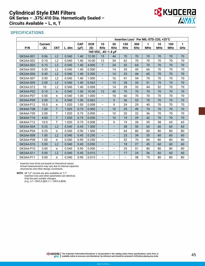
45The Important Information/Disclaimer is incorporated in the catalog where these specifications came from or available online at www.avx.com/disclaimer/ by reference and should be reviewed in full before placing any order.
– emi filters –
Cylindrical Style EMI Filters
SPECIFICATIONSInsertion Loss1 Per MIL-STD-220, +25°C
P/NCurrent
(A) CKT L. dimCAP (μF)
DCR (Ω)
10KHz
30KHz
150KHz
300KHz
1MHz
10MHz
100MHz
1GHz
100 VDC, .45–1.4 μFGK2AA-S01 0.06 L2 0.540 1.40 12.00 15 44 70 70 70 70 70 70GK2AA-S02 0.10 L2 0.540 1.40 10.00 12 34 62 70 70 70 70 70GK2AA-S03 0.15 L2 0.540 1.40 4.000 7 24 52 64 70 70 70 70GK2AA-S05 0.30 L2 0.540 1.40 0.500 – 14 35 45 66 70 70 70GK2AA-S06 0.45 L2 0.540 1.40 0.300 – 14 33 44 65 70 70 70GK2AA-S07 0.50 L2 0.540 1.40 1.000 – 16 41 54 70 70 70 70GK2AA-S09 2.00 L2 0.540 1.40 0.063 – 15 28 35 51 70 70 70GK2AA-S12 10 L2 0.540 1.40 0.008 – 14 28 33 44 52 70 70GK3AA-P02 0.10 π 0.540 1.00 10.00 12 40 70 70 70 70 70 70GK3AA-P07 0.50 π 0.540 1.00 1.000 – 18 60 70 70 70 70 70GK3AA-P09 2.00 π 0.540 1.00 0.063 – 9 36 53 70 70 70 70GK3AA-P12 10.0 π 1.020 1.00 0.008 – 9 24 29 40 70 70 70GK4AA-T08 1.00 T 1.020 0.75 0.500 – 10 25 49 70 70 70 70GK4AA-T09 2.00 T 1.020 0.75 0.090 – 10 20 32 56 70 70 70GK4AA-T16 4.00 T 1.020 0.75 0.030 – 10 19 29 42 70 70 70GK4AA-T12 10.0 T 1.020 0.75 0.008 – 9 19 28 39 58 65 65GK2AA-S04 0.25 L2 0.540 0.45 1.500 – – 38 50 60 60 60 60GK3AA-P04 0.25 π 0.540 0.90 1.500 – – 64 80 80 80 80 80GK2AA-S08 1.00 L2 0.540 0.45 0.250 – – 23 34 55 60 60 60GK3AA-P08 1.00 π 0.540 0.90 0.250 – – 52 70 80 80 80 80GK2AA-S10 3.00 L2 0.540 0.45 0.050 – – 18 27 45 60 60 60GK3AA-P10 3.00 π 0.540 0.90 0.050 – – 25 51 80 80 80 80GK2AA-S11 5.00 L2 0.540 0.45 0.015 – – 17 24 36 60 60 60GK3AA-P11 5.00 π 0.540 0.90 0.015 – – – 38 75 80 80 80
1 Insertion loss limits are based on theoretical values. Actual measurements may vary due to internal capacitor resonances and other design constraints.
NOTE: All “L2” circuits are also available as “L1”. Insertion loss and other parameters are identical. Only the part number changes (e.g., L2 = GK2LA-S04, L1 = GK2LA-R04).
GK Series – .375/.410 Dia. Hermetically Sealed – Circuits Available – L, π, T

46 The Important Information/Disclaimer is incorporated in the catalog where these specifications came from or available online at www.avx.com/disclaimer/ by reference and should be reviewed in full before placing any order.
– emi filters –
Cylindrical Style EMI Filters
SPECIFICATIONS
Insertion Loss1 Per MIL-STD-220, +25°C
P/NCurrent
(A) CKT L. dimCAP (μF)
DCR (Ω)
100KHz
150KHz
300KHz
1MHz
10MHz
100MHz
1GHz
150 VDC, .25–.50 μFGK2HA-S02 0.10 L2 0.540 0.250 1.700 32 39 51 60 60 60 70GK2HA-S05 0.30 L2 0.540 0.250 0.770 25 30 44 60 60 60 70GK2HA-S07 0.50 L2 0.540 0.250 36.00 20 26 39 59 60 60 70GK2HA-S08 1.00 L2 0.540 0.250 14.00 12 16 26 48 60 60 70GK2HA-S10 3.00 L2 0.540 0.250 0.050 11 15 20 36 60 60 70GK2HA-S11 5.00 L2 0.540 0.250 0.015 8 12 20 32 60 60 70GK2HA-S12 10.0 L2 0.540 0.250 0.008 6 12 20 32 40 56 70GK3HA-P02 0.10 π 0.540 0.500 1.700 49 60 70 80 80 80 80GK3HA-P05 0.30 π 0.540 0.500 0.770 43 53 70 80 80 80 80GK3HA-P07 0.50 π 0.540 0.500 0.360 37 48 66 80 80 80 80GK3HA-P08 1.00 π 0.540 0.500 0.140 28 40 58 80 80 80 80GK3HA-P10 3.00 π 0.540 0.500 0.050 – – 38 70 80 80 80GK3HA-P11 5.00 π 0.540 0.500 0.015 – – 20 63 80 80 80GK3HA-P12 10.0 π 0.540 0.500 0.008 – – 15 35 60 80 80GK4HA-T08 1.00 T 1.020 0.250 0.500 15 23 42 70 80 80 80GK4HA-T09 2.00 T 1.020 0.250 0.090 9 13 32 50 70 80 80GK4HA-T16 4.00 T 1.020 0.250 0.030 6 10 21 40 60 80 80GK4HA-T12 10.0 T 1.020 0.250 0.006 – 9 21 28 44 60 80
200 VDC, .15–.36 μF
P/NCurrent
(A) CKT L. dimCAP (μF)
DCR (Ω)
10KHz
30KHz
150KHz
300KHz
1MHz
10MHz
100MHz
1GHz
GK2BA-S02 0.10 L2 0.540 0.150 10.00 – 21 50 61 70 70 70 70GK2BA-S04 0.25 L2 0.540 0.150 0.400 – 11 39 51 70 70 70 70GK2BA-S07 0.50 L2 0.540 0.150 1.000 – 3 29 41 63 70 70 70GK2BA-S08 1.00 L2 0.540 0.150 0.250 – – 18 28 49 70 70 70GK2BA-S09 2.00 L2 0.540 0.150 0.063 – – 15 21 38 70 70 70GK2BA-S10 3.00 L2 0.540 0.150 0.027 – – 15 21 31 70 70 70GK2BA-S12 10.0 L2 0.540 0.150 0.008 – – 15 21 31 51 60 60GK3BA-P02 0.10 π 0.540 0.360 10.00 – 21 61 70 70 70 70 70GK3BA-P04 0.25 π 0.540 0.360 4.000 – 10 52 68 70 70 70 70GK3BA-P07 0.50 π 0.540 0.360 1.000 – – 44 63 70 70 70 70GK3BA-P08 1.00 π 0.540 0.360 0.250 – – 30 46 70 70 70 70GK3BA-P09 2.00 π 0.540 0.360 0.063 – – 16 33 63 70 70 70GK3BA-P10 3.00 π 0.540 0.360 0.027 – – – 21 55 70 70 70GK3BA-P12 10.0 π 0.540 0.360 0.008 – – – 20 30 60 70 70GK4BA-T08 1.00 T 1.020 0.150 0.500 – 3 17 42 70 70 70 70GK4BA-T09 2.00 T 1.020 0.150 0.090 – – 12 24 48 70 70 70GK4BA-T16 4.00 T 1.020 0.150 0.030 – – 12 21 34 70 70 70GK4BA-T12 10.0 T 1.020 0.150 0.008 – 3 12 21 31 50 60 60
1 Insertion loss limits are based on theoretical values. Actual measurements may vary due to internal capacitor resonances and other design constraints.
NOTE: All “L2” circuits are also available as “L1”. Insertion loss and other parameters are identical. Only the part number changes (e.g., L2 = GK2LA-S04, L1 = GK2LA-R04).
GK Series – .375/.410 Dia. – Hermetically Sealed – Circuits Available – L, π, T

47The Important Information/Disclaimer is incorporated in the catalog where these specifications came from or available online at www.avx.com/disclaimer/ by reference and should be reviewed in full before placing any order.
– emi filters –
Cylindrical Style EMI Filters
SPECIFICATIONS
Insertion Loss1 Per MIL-STD-220, +25°C
P/NCurrent
(A) CKT L. dimCAP (μF)
DCR (Ω)
10KHz
30KHz
150KHz
300KHz
1MHz
10MHz
100MHz
1GHz
200 VDC (125 VAC/400 Hz) .15–.30 μFGK2LA-S02 0.10 L2 0.540 0.150 10.00 – 14 42 54 70 70 70 70GK2LA-S07 0.50 L2 0.540 0.150 1.000 – – 23 35 56 70 70 70GK2LA-S09 2.00 L2 0.540 0.150 0.063 – – 8 14 30 70 70 70GK2LA-S12 10.0 L2 0.540 0.150 0.008 – – 8 14 25 45 60 60GK3LA-P02 0.10 π 0.540 0.300 10.00 – 21 60 70 70 70 70 70GK3LA-P07 0.50 π 0.540 0.300 1.000 – – 40 56 70 70 70 70GK3LA-P10 3.00 π 0.540 0.300 0.027 – – – 25 54 70 70 70GK3LA-P12 10.0 π 0.540 0.300 0.008 – – – 20 30 70 70 70GK2LA-S04 0.25 L2 0.540 0.150 1.500 – 6 28 40 60 60 60 70GK2LA-S08 1.00 L2 0.540 0.150 0.250 – – 13 24 45 60 60 70GK2LA-S10 3.00 L1 0.540 0.150 0.050 – – 8 16 30 60 60 70GK2LA-S11 5.00 L2 0.540 0.150 0.015 – – 8 14 26 55 55 70GK3LA-P04 0.25 π 0.540 0.300 1.500 – 8 44 62 80 80 80 80GK3LA-P08 1.00 π 0.540 0.300 0.250 – – 32 50 80 80 80 80GK3LA-P10 3.00 π 0.540 0.300 0.050 – – – 19 59 80 80 80GK3LA-P11 5.00 π 0.540 0.300 0.015 – – – – 51 80 80 80GK4LA-T08 1.00 T 1.020 0.150 0.500 – – 10 36 66 70 70 70GK4LA-T09 2.00 T 1.020 0.150 0.090 – – 7 18 41 70 70 70GK4LA-T16 4.00 T 1.020 0.150 0.030 – – 8 15 27 70 70 70GK4LA-T12 10.0 T 1.020 0.150 0.008 – – 8 15 25 70 70 70
1 Insertion loss limits are based on theoretical values. Actual measurements may vary due to internal capacitor resonances and other design constraints.
NOTE: All “L2” circuits are also available as “L1”. Insertion loss and other parameters are identical. Only the part number changes (e.g., L2 = GK2LA-S04, L1 = GK2LA-R04).
GK Series – .375/.410 Dia. Hermetically Sealed – Circuits Available – L, π, T

48 The Important Information/Disclaimer is incorporated in the catalog where these specifications came from or available online at www.avx.com/disclaimer/ by reference and should be reviewed in full before placing any order.
– emi filters –
Cylindrical Style EMI FiltersJD Series – .690 Dia. Hermetically Sealed – Circuits Available – C, L, π, T
The JD series offers effective filtering from 14 KHz to 10 GHz. The large diameter, increased length, restricted capacitance values and conservative dielectrics of the JD series are particularly important design features for 400 Hz AC applications where high reactive currents and the resultant heat dissipation must be controlled. Glass sealed on both ends for hermeticity, this series is impervious to high moisture, solvents, or other severe environmental conditions commonly encountered in military applications. It is designed for bulkhead mounting in a slotted hole with nut and lockwasher supplied.The 230 VAC “T” section style is uniquely capable of handling very high pulse inrush currents or overvoltage conditions typical of EMP.In addition, transient voltage suppression devices can be added to any of the JD circuit designs to provide complete circuit protection against EMP, lightning, or voltage spikes such as MIL-STD-704. These devices when combined with high frequency attenuation characteristics of the discoidal capacitor and toroidal inductors offer significant performance advantages by suppressing and absorbing the EMP pulse
over a very broad spectral range. Very high pulse currents will occur within the EMI filter, however, reradiation to sensitive electronic circuits is prevented by the fully shielded case design. In some cases a slight increase in the case length of the filter is required to provide space for the transient suppression device.The “L”, and the “T” designs are designed to provide effective attenuation over a wide range of circuit impedances. For current ratings under 15 Amps toroidal wound inductor elements offer increased filter performance and protection against circuit transients. Data showing the actual inductance versus various levels of DC or AC bias current are available as well as the attenuation in any combination of source and load impedance.Alternate lead configurations or special capacitance/inductance values may be ordered.Custom packages or filter arrays utilizing the JD series can be furnished.
APPLICATIONS
CHARACTERISTICS
SPECIFICATIONS
• Designed to meet the requirements of DESC drawings 84083, 84084 and MIL-F-28861/16 and /17.
• Glass hermetic seal on both ends.
• Wound toroidal inductor used in designs up to 10 Amps. 15
• Amp designs incorporate ferrite bead inductor.
• Superior heat dissipation for both 125 VAC and 230 VAC designs.
1. Case/Terminal Plating: Electro-tin standard – Silver or gold available
2. Material:Case: Brass standard – Steel availableEnd Seal: Mild steelTerminals: Nickel-iron alloy
3. Operating Temperature Range: -55°C to +125°C
4. Electrical Characteristics:A. Rated Voltage
300 VDC/125 VAC, 400 Hz or400 VDC/230 VAC, 400 Hz
B. Current Rating - see chart
C. Insulation Resistance:At 25°C: 1,000 megohm-microfarad
min., or 50,000 megohms min., whichever is less, at the rated DC voltage
At 125°C: 100 megohm-microfarad min., or 10,000 megohms min., whichever is less
D. Dielectric Withstanding Voltage (DWV): R-level designs:
2.0 times rated DC voltageClass B, Class S designs:
2.5 times rated DC voltage3. Capacitance: Total capacitance listed in
chart for each filter type is “guaranteed minimum value” (GMV)
5. Marking:Standard Marking: KYOCERA AVX, KYOCERA AVX part number, rated voltage, current, lot number, schematic
NOTE: Schematic to indicate location of inductor (standard or reverse) for JD2 L-Section Filters. See Reliability Codes section for definition of Reliability Level marking. See How to Order section for part number construction.
6. Installation:A. Mounting Torque: 60 oz-in. ± 4 oz-in.B. Refer to “Installation and Handling”
section of Filter Design Guide

49The Important Information/Disclaimer is incorporated in the catalog where these specifications came from or available online at www.avx.com/disclaimer/ by reference and should be reviewed in full before placing any order.
– emi filters –
Cylindrical Style EMI FiltersJD Series – .690 Dia. Hermetically Sealed – Circuits Available – C, L, π, T
C
JD1
.3125-24 UNF-2A (5/16-24)
.062 ± .015 x .125 ± .015(2 PLC)
.062MAX.
.250±.015
.620MAX.
LMAX.
(See Note 1)
.290MAX.
.312±.010
.690MAX.
.120±.020
(2 PLC)
CIRCUIT DIAGRAMS
STANDARD CONFIGURATION
JD2 - Standard
THRDEND
L2 Pi
JD3 JD2 - Reverse
THRDEND
L1
T
JD4
millimeters (inches)
MIL-F-28861/17(See P/N Table)
MIL-F-28861/16(See P/N Table)
(See Note 2)
(See Note 2)
Notes:1. Refer to Part Number Table
for L-Max for specific filter.2. Metric equivalent dimensions
given for information only.3. All dimensions for JD series
filters established per MIL-F-28861/16 and /17, and DESC 84083 and 84084 requirements.
0.08 (.003) 6.35 (.250)0.13 (.005) 7.37 (.290)0.18 (.007) 7.92 (.312)0.25 (.010) 9.53 (.375)0.38 (.015) 10.67 (.420)0.51 (.020) 11.18 (.440)0.56 (.022) 15.75 (.620)1.14 (.045) 17.27 (.680)1.57 (.062) 17.78 (.700)2.36 (.093) 26.92 (1.060)3.05 (.120) 30.61 (1.205)3.18 (.125) 33.02 (1.300)
Dash No.
L Dimension
Max.
Weight (grams)
Max.001 .700 18.0002 1.060 20.0003 1.060 20.0004 1.060 20.0005 1.060 20.0006 1.060 20.0007 1.060 20.0008 1.060 20.0009 1.060 20.0010 1.060 20.0011 1.060 20.0012 1.205 29.0013 1.205 29.0014 1.205 29.0015 1.205 29.0016 1.205 29.0017 1.300 29.0018 1.300 29.0019 1.300 29.0
Dash No.
L Dimension
Max.001 .700
002 through 011 1.060012 through 016 1.205017 through 019 1.300
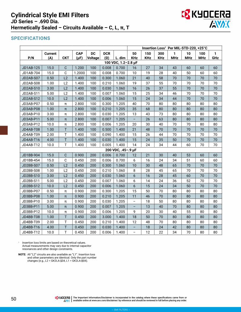
50 The Important Information/Disclaimer is incorporated in the catalog where these specifications came from or available online at www.avx.com/disclaimer/ by reference and should be reviewed in full before placing any order.
– emi filters –
Cylindrical Style EMI FiltersJD Series – .690 Dia. Hermetically Sealed – Circuits Available – C, L, π, T
SPECIFICATIONS
Insertion Loss1 Per MIL-STD-220, +25°C
P/NCurrent
(A) CKTCAP (μF)
DCVoltage
DCR (Ω) L. dim
50KHz
150KHz
300KHz
1MHz
10MHz
100MHz
1GHz
100 VDC, 1.2–2.8 μFJD1AB-125 15.0 C 1.200 100 0.008 0.700 16 27 34 43 60 60 60JD1AB-704 15.0 C 1.2000 100 0.008 0.700 10 19 28 40 50 60 60JD2AB-S07 0.50 L2 1.400 100 0.300 1.060 21 40 58 70 70 70 70JD2AB-S08 1.00 L2 1.400 100 0.210 1.060 19 37 55 70 70 70 70JD2AB-S10 3.00 L2 1.400 100 0.030 1.060 16 26 37 55 70 70 70JD2AB-S11 5.00 L2 1.400 100 0.007 1.060 15 25 34 46 70 70 70JD2AB-S12 10.0 L2 1.400 100 0.006 1.060 15 24 34 44 70 70 70JD3AB-P07 0.50 π 2.800 100 0.300 1.205 40 70 80 80 80 80 80JD3AB-P08 1.00 π 2.800 100 0.210 1.205 35 68 80 80 80 80 80JD3AB-P10 3.00 π 2.800 100 0.030 1.205 13 43 73 80 80 80 80JD3AB-P11 5.00 π 2.800 100 0.007 1.205 – 26 63 80 80 80 80JD3AB-P12 10.0 π 2.800 100 0.006 1.205 20 30 40 70 70 80 80JD4AB-T08 1.00 T 1.400 100 0.500 1.400 21 48 70 70 70 70 70JD4AB-T09 2.00 T 1.400 100 0.090 1.400 15 26 44 70 70 70 70JD4AB-T16 4.00 T 1.400 100 0.030 1.400 15 24 35 50 70 70 70JD4AB-T12 10.0 T 1.400 100 0.005 1.400 14 24 34 44 60 70 70
200 VDC, .45–.9 μFJD1BB-904 15.0 C 0.900 200 0.006 0.700 12 21 30 40 53 60 60JD1BB-454 15.0 C 0.450 200 0.006 0.700 6 16 24 34 51 60 60JD2BB-S07 0.50 L2 0.450 200 0.300 1.060 10 30 48 65 70 70 70JD2BB-S08 1.00 L2 0.450 200 0.210 1.060 8 28 45 65 70 70 70JD2BB-S10 3.00 L2 0.450 200 0.030 1.060 6 16 28 45 60 70 70JD2BB-S11 5.00 L2 0.450 200 0.007 1.060 6 14 24 36 52 70 70JD2BB-S12 10.0 L2 0.450 200 0.006 1.060 6 15 24 34 50 70 70JD3BB-P07 0.50 π 0.900 200 0.300 1.205 15 50 70 80 80 80 80JD3BB-P08 1.00 π 0.900 200 0.210 1.205 11 46 70 80 80 80 80JD3BB-P10 3.00 π 0.900 200 0.030 1.205 – 18 50 80 80 80 80JD3BB-P11 5.00 π 0.900 200 0.007 1.205 – 13 40 70 80 80 80JD3BB-P12 10.0 π 0.900 200 0.006 1.205 9 20 30 40 55 80 80JD4BB-T08 1.00 T 0.450 200 3.000 1.400 18 50 70 80 80 80 80JD4BB-T09 2.00 T 0.450 200 0.210 1.400 12 48 70 80 80 80 80JD4BB-T16 4.00 T 0.450 200 0.030 1.400 – 18 24 42 80 80 80JD4BB-T12 10.0 T 0.450 200 0.006 1.400 – 12 22 34 70 80 80
1 Insertion loss limits are based on theoretical values. Actual measurements may vary due to internal capacitor resonances and other design constraints.
NOTE: All “L2” circuits are also available as “L1”. Insertion loss and other parameters are identical. Only the part number changes (e.g., L2 = GK2LA-S04, L1 = GK2LA-R04).

51The Important Information/Disclaimer is incorporated in the catalog where these specifications came from or available online at www.avx.com/disclaimer/ by reference and should be reviewed in full before placing any order.
– emi filters –
Cylindrical Style EMI FiltersJD Series – .690 Dia. Hermetically Sealed – Circuits Available – C, L, π, T
SPECIFICATIONS
Insertion Loss1 Per MIL-STD-220, +25°C
P/NCurrent
(A) CKTCAP (μF)
DCVoltage
DCR (Ω) L. dim
50KHz
150KHz
300KHz
1MHz
10MHz
100MHz
1GHz
300 VDC (125 VAC/400Hz*), .3–.36 μFJD1LB-304 15.0 C 0.300 300 0.008 0.700 7 16 22 32 46 58 70JD2LB-S07 0.50 L2 0.300 300 0.330 1.060 13 28 40 60 60 70 70JD2LB-S08 1.00 L2 0.300 300 0.150 1.060 6 24 37 56 60 70 70JD2LB-S10 3.00 L2 0.300 300 0.026 1.060 7 17 24 42 70 70 70JD2LB-S11 5.00 L2 0.300 300 0.013 1.060 7 16 22 34 68 70 70JD2LB-S12 10.0 L2 0.300 300 0.008 1.060 7 16 20 30 56 70 70JD3LB-P07 0.50 π 0.360 300 0.330 1.205 14 44 62 80 80 80 80JD3LB-P08 1.00 π 0.360 300 0.150 1.205 – 37 56 80 80 80 80JD3LB-P10 3.00 π 0.360 300 0.026 1.205 – 18 40 70 80 80 80JD3LB-P11 5.00 π 0.360 300 0.013 1.205 – – 25 60 80 80 80JD3LB-P12 10.0 π 0.360 300 0.008 1.205 – – – 50 80 80 80JD4LB-T08 1.00 T 0.300 300 0.070 1.400 6 18 28 58 70 70 70JD4LB-T09 2.00 T 0.300 300 0.050 1.400 6 16 22 37 70 70 70JD4LB-T16 4.00 T 0.300 300 0.030 1.400 6 16 20 34 70 70 70JD4LB-T12 10.0 T 0.300 300 0.008 1.400 – – 19 30 48 60 70
400 VDC (230 VAC/400Hz*), .15–.2 μFJD1EB-154 15.0 C 0.150 400 0.008 .700 – 10 16 26 40 52 70JD2EB-S07 0.50 L2 0.150 400 0.330 1.060 5 24 32 50 60 70 70JD2EB-S08 1.00 L2 0.150 400 0.150 1.060 – 19 30 46 60 70 70JD2EB-S10 3.00 L2 0.150 400 0.026 1.060 – 11 19 36 60 70 70JD2EB-S11 5.00 L2 0.150 400 0.013 1.060 – 10 16 28 54 70 70JD2EB-S12 10.0 L2 0.150 400 0.008 1.060 – 10 16 25 48 70 70JD3EB-P07 0.50 π 0.200 400 0.330 1.205 – 34 52 80 80 80 80JD3EB-P08 1.00 π 0.200 400 0.150 1.205 – 27 46 74 80 80 80JD3EB-P10 3.00 π 0.200 400 0.026 1.205 – – 30 60 80 80 80JD3EB-P11 5.00 π 0.200 400 0.013 1.205 – – 12 50 80 80 80JD3EB-P12 10.0 π 0.200 400 0.008 1.205 – – – 30 80 80 80JD4EB-T08 1.00 T 0.150 400 0.070 1.300 – 12 25 48 70 70 70JD4EB-T09 2.00 T 0.150 400 0.050 1.300 – 10 18 40 64 70 70JD4EB-T16 4.00 T 0.150 400 0.030 1.300 – 10 16 31 58 70 70JD4EB-T12 10.0 T 0.150 400 0.008 1.300 – – 15 25 45 60 70
1 Insertion loss limits are based on theoretical values. Actual measurements may vary due to internal capacitor resonances and other design constraints.
NOTE: All “L2” circuits are also available as “L1”. Insertion loss and other parameters are identical. Only the part number changes (e.g., L2 = GK2LA-S04, L1 = GK2LA-R04).

52
– emi filters –
The Important Information/Disclaimer is incorporated in the catalog where these specifications came from or available online at www.avx.com/disclaimer/ by reference and should be reviewed in full before placing any order.
Filter PlatesCustom Designed Filter Plates

53The Important Information/Disclaimer is incorporated in the catalog where these specifications came from or available online at www.avx.com/disclaimer/ by reference and should be reviewed in full before placing any order.
– emi filters –
Filter PlatesCustom Designed Filter Plates
KYOCERA AVX solder-in style filters are designed to be soldered into bulkheads, plates, and/or assemblies similar to those depicted in the photograph above. KYOCERA AVX Filters will design and fabricate bracket arrays to your specific requirements or Source Control Drawing.The mechanical stress and extreme temperatures encountered by the filters during installation into assemblies is normally the harshest environment they will experience during the life of a system.If you are buying the discrete filters and doing the installation in house you should seriously consider:
• How much is it costing you to purchase burned-in and fully tested filters only to damage them during the installation procedure?
• How much is it costing you to test for component integrity after installation?
• How much is it costing you to rework damaged filter assemblies at your labor rates and overhead?
• How much is it costing you to contend with low assembly yields?
• How much is it costing you to inventory a larger number of line items than necessary?
KYOCERA AVX Filters will design and fabricate filter brackets: • To your specific requirements.• 100% tested and burned-in prior to delivery.• Which utilize the superior solder-in style filters (Series
ZZ, ZS, XS, WS) capable of withstanding installation temperatures up to 300°C, or
• Which utilize the new hermetic solder-in when harsh environments or other requirements call for true hermetic components.
A custom designed filter bracket will help: • To reduce your yield losses.• To eliminate filter rework in assemblies.• To reduce system assembly costs.• To minimize your inventory.
For additional information on filter brackets or design assistance, contact the KYOCERA AVX Filters Application Engineering Department.

54 The Important Information/Disclaimer is incorporated in the catalog where these specifications came from or available online at www.avx.com/disclaimer/ by reference and should be reviewed in full before placing any order.
– emi filters –
Filter Plates
SPECIFICATIONS AND CAPABILITIES
Size: Basically unlimited. The physical size is determined by the quantity and style (WS, YS, etc.) of filters selected.Construction: Hand fabricated or machined metallic (steel, brass, aluminum, or other alloys) bracket.Finish Options: The bracket can be electro-tin plated, gold plated, anodized, chem film, painted, or as specified by the customer.The individual filter terminals can be gold plated or solder coated.Electrical Characteristics: The following electrical parameters are governed by the individual types of filters selected or as dictated by the customer’s Source Control Drawing or specific application.
Voltage Rating Current Rating Insulation Resistance DWV DC Resistance Insertion Loss Operating Temperature
Discrete Components: The number of components, individual circuits, can range from 2 to 200 filters of different styles and/or electrical characteristics (WS, YS, etc.) and can be combined to form a single custom assembly.Discrete Component Testing: QPL and/or QPL equivalents can be utilized.Discoidal capacitors can be designed and tested to the requirements of MIL-C-123.
The individual filters can be specified with MIL-F-15733, KYOCERA AVX Filters Level R, MIL-F-28861 Class B or Class S reliability levels (see Reliability section of catalog for description) or as dictated by the customer’s Source Control Drawing or specific application.Bracket Assembly: The complete bracket assembly can be tested to similar requirements as the individual filters.Hermeticity: Some brackets are more cost effective and volumetrically efficient as non-hermetic assemblies where application allows.Most brackets can be manufactured to provide a hermetic barrier (glass-to-metal seal) on one side of the assembly.There are true hermetic brackets, glass-to-metal seals on both sides available, but only in a capacitive circuit.Installation Temperature: Filter bracket assemblies are capable of withstanding installation temperatures up to 300°C.Additional Assembly Operations: Wiring harnesses or flex cables can be attached to the complete assembly and completely tested prior to delivery.Environmental Considerations: Capable of meeting the applicable portions of MIL-STD-202 and MIL-STD-810.

55
– emi filters –
The Important Information/Disclaimer is incorporated in the catalog where these specifications came from or available online at www.avx.com/disclaimer/ by reference and should be reviewed in full before placing any order.
Filter Design GuideHigh Reliability

56 The Important Information/Disclaimer is incorporated in the catalog where these specifications came from or available online at www.avx.com/disclaimer/ by reference and should be reviewed in full before placing any order.
– emi filters –
Filter Design GuideHigh Reliability
M28861 SCREENING
R-LEVEL SCREENING
The Group A sequence as outlined in MIL-F-28861 is performed on a 100% basis whenever Reliability Codes for Class S or Class
B are specified by the customer. Differences between Class S and Class B screening are shown in the descriptions.
The test sequence outlined below is performed whenever KYOCERA AVX Filters R-level screening is specified. Each filter lot is subjected to the tests in the order shown on a 100% basis. Summary data is provided for R-level Screening and is included with shipment.
S-CLASS, B-CLASS TESTING
S-CLASS, B-CLASS TESTING
TestMIL-STD-202 (method) Description
Thermal Shock 107, cond. A S-class: 5 cycles from -55°C to +125°C. Through-hole mounting required. B-class: as above except mounting not required.
Burn-in 108 S-class: 168 hours minimum at 2.0X rated voltage, 125°C polarity reversal for the first 24-72 hours; fused B/I circuit for each filter. B-class: 164 ± 4 hours at 2.0X rated voltage.
Dielectric Withstanding Voltage
301 S-class, B-class: 2.5X rated DC voltage for 5 seconds minimum, 1 minute maximum, 50 mA charging current.
Insulation Resistance
302, cond. A S-class: test at 100 VDC or rated, V, whichever is less. Pass/fail limits are also based upon 125°C reading from first 50 pieces. B-class: same as above, except omit pass/fail as per 50 piece calculation.
Capacitance and D.F. 305 S-class, B-class: test 1000 ± 100 Hz, 0.1 to 1.2 VRMSInsertion Loss — S-class, B-class: per MIL-STD 220 at load, no-load as specified.DC Resistance 303 S-class, B-class: test is optional if DC Voltage Drop Test performed.Voltage Drop — S-class, B-class: M28861 para. 4.6.6.1 (AC rated), para 4.6.6.2 (DC rated)Radiographic Inspect. 209 S-class, B-class: 2 views required with 10X examination images.Seal Test 112 S-class: condition C, B-class: condition A or DVisual and Mechanical — S-class: M28861 para 4.6.1.2 which includes element, subassembly, and pre-cap
inspections, B-class: M28861 para 4.6.3 for external visual only.Solderability 208 S-class, B-class: 5 samples.
TestMIL-STD-202 (method) Description
Thermal Shock 107, cond. A 5 cycles from -55°C to +125°C.Burn-in 108, cond. A 100 hours at 1.4 times rated voltage, ±125°C.Dielectric Withstanding Voltage
301 Twice (2X) rated DC voltage for 5 ± 1 sec at 25°C, 50 mA maximum charging current.
Insulation Resistance 302, cond. A Testing performed at rated DC voltage. The 125°C value shall be 10% of the specified IR at 25°C.
Seal Test 112, cond. A Gross leak test. Not applicable to epoxy-sealed units.Depolarization — 1 hour at 150°C. No voltage applied.Capacitance and D.F.
305 Test signal 1KHz, 1.0 VRMS.
DC Resistance 303 DCR measured in lieu of voltage drop.Insertion Loss — Per MIL-F-15733 para 4.6.9.1 (check test)Visual and Mechanical — Per MIL-F-15733 para. 4.6.1

57The Important Information/Disclaimer is incorporated in the catalog where these specifications came from or available online at www.avx.com/disclaimer/ by reference and should be reviewed in full before placing any order.
– emi filters –
Screw & Locking Washer Table
HEX NUT AND INTERNAL TOOTH LOCKWASHER
THREAD
DCBA
HEX NUT WASHER
Size Thread Hex Nut LockwasherA B C D
4-40 UNC-2B(.112-40) (STD) .187*
.180.067*.057
.225*.215
.020*.010
(ALT) .257.241
.083
.073.265.255
.018
.0128-32 UNC-2B(.164-32) (STD) .250*
.241.083*.073
.285*.275
.025*.015
(ALT) .313.307
.114
.104.336.325
.025
.01510-32 UNF-2B(.190-32) (STD) .250
.241.080.070
.311
.300.023.013
(ALT) .345.336
.130
.120.381.370
.027
.01712-32 UNEF-2B(.216-32) (STD) .250
.241.083.073
.383
.372.023.013
(ALT) .250*.241
.073*.063
.383*.372
.023*.013
1/4-28 UNF-2B(.250-28)
.311*.308
.096*.091
.408*.396
.021*.015
5/16-24 UNF-2B(.312-24)
.377*.365
.096*.091
.435*.425
.027*.017
*Used for MIL-F-28861 units.
Thread Recommended Mounting Torque(.112-40)4-40 UNC-2A 32 oz-in. ± 4 oz-in.
(.164-32)8-32 UNC-2A 64 oz-in. ± 4 oz-in.
(.190-32)10-32 UNC-2A 64 oz-in. ± 4 oz-in.
(.216-32)12-32 UNEF-2A 64 oz-in. ± 4 oz-in.
(.250-28)1/4-28 UNF-2A 44 oz-in. ± 4 oz-in.
(.312-24)5/16-24 UNF-2A 60 oz-in. ± 4 oz-in.
58
– emi filters –
The Important Information/Disclaimer is incorporated in the catalog where these specifications came from or available online at www.avx.com/disclaimer/ by reference and should be reviewed in full before placing any order.
Filter Types

59The Important Information/Disclaimer is incorporated in the catalog where these specifications came from or available online at www.avx.com/disclaimer/ by reference and should be reviewed in full before placing any order.
– emi filters –
Filter Types
C FEED-
THRU FILTER C
A feedthru is a low inductance device, acting as a bypass feedthru capacitor to ground. It works well with a high impedance load and source. For assured contact, it should be soldered directly to a bulkhead or a connector base.
L FILTERL1
L2
This adds a series-inductive element to the bypass feedthru capacitor connected to ground. Because of the inductor, it can be connected to a low impedance source or load. This filter may be used to link a low impedance source to a high impedance load, or vice versa, with the feedthru capacitor facing the high impedance circuit.
π FILTERPi
This filter contains two feedthru capacitors connected to ground with an inductor in-between. It presents a low impedance to both the source and load, and has a sharper roll-off than either the feed-thru or L-section designs. With feedthru capacitors as outer elements, this filter is best suited for high impedance load and source applications.
T FILTERT
This filter forms a 'T' with two inductors and a feedthru capacitor connected to ground. Like the π Filter, it has a sharper roll-off than a feedthru or an L-section design. With inductors as outer elements, the T-section is intended for applications with a low impedance load and source. It also finds application where transient conditions may occur (EMP, lighting, etc).
TL
C
100
80
60
40
20
010 KHz 100 KHz 1 MHz
FREQUENCY
INS
ER
TIO
N L
OS
S (d
B)
10 MHz 100 MHz
I.L. vs. FREQUENCY(FOR VARIOUS FILTER CONFIGURATIONS)INSERTION LOSS
The insertion loss values specified throughout this catalog are based upon an industry standard of full load and balanced 50 ohm system in accordance with MIL-STD-220A (at +25°C). The actual attenuation performance in other circuits will vary significantly with different values of source and load impedance. The insertion loss values in this catalog may appear to be significantly lower than that of comparable filters in certain other competitor catalogs. The reason for this is that KYOCERA AVX Filters takes into account both component and circuit resonances and adjusts the table values such that the insertion loss will not drop below straight lines drawn between each data point in a semilog graph.

60
– emi filters –
The Important Information/Disclaimer is incorporated in the catalog where these specifications came from or available online at www.avx.com/disclaimer/ by reference and should be reviewed in full before placing any order.
Filter Design GuideHigh Reliability

61The Important Information/Disclaimer is incorporated in the catalog where these specifications came from or available online at www.avx.com/disclaimer/ by reference and should be reviewed in full before placing any order.
– emi filters –
Filter Design GuideHigh Reliability
INSTALLATION, HANDLING, HARDWARE OPTIONS
GENERAL Proper Electrical Operation Requires:
• Good filter/case ground.• Design layout where filter is installed directly into
conductive shield or enclosure.• Minimizing holes, slots, or other penetrations of the shield
near the filter.
Installation Precautions • Although EMI/RFI filters can withstand temperature
extremes, rapid heat-up or cool-down can crack the internal ceramic capacitor.
– Pre-heating of the filter prior to soldering should be performed whenever possible.
– Forced-air cooling after soldering is not recommended.
Avoid Mechanical Stress • Do not use pliers or other gripping tools capable of
exerting excessive pressure on filter case.• Do not alter the lead or terminal flag either before or after
soldering.
SPECIFIC RECOMMENDATIONS Hi-Temp Solder-In Style Filter
• Small case design sensitive to excessive heating.• 150°C preheat prior to solder installation using supplied
solder preform highly recommended.• Vapor phase reflow (VPR) soldering with integral preheat
is preferred.• Infrared (IR) and hot plate soldering may also be used.• Temperature should be increased to solder temperature
(300°C, max.) at a controlled rate of 2°C per second.• Time at max. temperature should be kept at a minimum
and should never exceed 30 seconds.• When soldering leads using an iron: — Iron tip
temperature should not exceed 460°F (60/40 solder recommended).
– Use a small iron, 15-20 watts, and do not apply heat for longer than 10 seconds.
– Use of heat sink clip when lead length permits is recommended.
• Do not expose leads to torque stresses by moving wires after soldering to lead. The glass hermetic seal may be damaged.
• Do not cut or form filter leads. – Mechanical stress may be transmitted to the discoidal capacitor.
– The glass hermetic seal may be damaged. – Contact KYOCERA AVX Filters regarding custom lead lengths to accommodate your requirements.
Bolt-Style Filters • Do not exceed recommended nut mounting torques listed
on next page. NOTE: it is preferable to keep to the low side of torque range when installing filters into threaded mounting holes.
• On epoxy sealed bolt-style units KYOCERA AVX Filters recommends conformal coating of the units after installation to improve moisture resistance.
• Observe same precautions listed for hi-temp filter when soldering to filter center pin.
• Do not bend filter center pin.
Cylindrical-Style Filters • Observe recommended nut mounting torque as per the
table on next page. – BK, CK, GK – series filters (1/4-28 UNF-2A) require 44 ± 4 oz-in.
– JD series (5/16-24 UNF-2A) require 60 ± 4 oz-in.• The terminal flags should not be subjected to mechanical
stress during or after leadwire installation. The glass hermetic seal may be adversely affected.
• Use care in soldering to the terminal flags. An 18-30 watt soldering iron is recommended. CAUTION: the use of a large wattage iron without temperature control may cause reflow of the high-temperature solder used to seal the terminal. This could result in the loss of hermeticity for the filter.
HARDWARE OPTIONS
General • Necessary mounting hardware is supplied with all filters.• Hex nut and lockwasher plating will be as per filter case
specified.• Refer to table for hardware selection. Standard hardware
(“STD”) will be supplied unless otherwise requested. MIL-F-28861 filters will be shipped with MIL-F-28861 hardware.
Only ZXS, ZYS, and ZZS are RoHS compliant and leadfree.All other products are considered Not RoHS Compliant unless otherwise indicated

62
– emi filters –
The Important Information/Disclaimer is incorporated in the catalog where these specifications came from or available online at www.avx.com/disclaimer/ by reference and should be reviewed in full before placing any order.
Military Qualified Products

63The Important Information/Disclaimer is incorporated in the catalog where these specifications came from or available online at www.avx.com/disclaimer/ by reference and should be reviewed in full before placing any order.
– emi filters –
Military Qualified Products
There have been many questions raised regarding the differences between MIL-F-15733 and MIL-F-28861. To clarify these differences we have incorporated the following Analysis
Chart which compares the differences between these two military specifications.
ANALYSIS MIL-F-15733 vs. MIL-F-28861MIL-F-15733 MIL-F-28861
Characteristics Filter Design/ Construction
Filter Design/Construction
Class B Class SCASE Standard Standard StandardCAPACITOR(Discoidal)• Dielectrics• K• VTL• Cap Range
Standard
X7R, Z5U 2200-10KN/AMax Cap/Case Size
Special Design
BR2K max+15%, -40%Limited Cap/Case Size Conservation Design
Special Design
BX2K max+15%, -25% (when design permits) Limited Cap/Case Size &MIL-C-123 Req’ts Conservative Design
Testing TestingGROUP A• Test• PDA
(parts defective allowed)
MIL-STD-105,
1.0% AQLNone
100% Test
10%
100% Test
Thermal Shock, Burn-in*, IR & DWV–2% each test Cap, Volt. Drop, InsertionLoss -3% max combined Total 10% max
X-RAY None MIL-STD-202Method 209
MIL-STD-202Method 209
LEAK TEST Condition “A” Gross Leak
Condition “A” Gross Leak
PDA 10% max
Condition “A” Gross Leak
Condition “C” Fine Leak PDA 10% max
BURN-IN None generally. A few slash sheets require1.4 x rated voltage
160 Hrs. @ 2 x ratedvoltage — Resistor protected
168 Hrs. (250 Hrs. max) @ 2 x rated voltage - Fuse protected *PDA .2% max lasts 50 Hrs.
INSERTION LOSS 1.0% AQL 100% 100%
SOLDERABILITY None MIL-STD-202Method 2085 Samples
MIL-STD-202Method 2085 Samples

64
– emi filters –
The Important Information/Disclaimer is incorporated in the catalog where these specifications came from or available online at www.avx.com/disclaimer/ by reference and should be reviewed in full before placing any order.
How To OrderNotes
65The Important Information/Disclaimer is incorporated in the catalog where these specifications came from or available online at www.avx.com/disclaimer/ by reference and should be reviewed in full before placing any order.
– emi filters –
How To OrderNotes
NOTE 1: CAPACITANCE CODE All KYOCERA AVX Filters part numbers, with exception of certain cylindrical styles, show total filter capacitance using the 3-digit EIA code. The first two digits are significant: the last digit is the multiplier.Example: 103= 10000 picofarads 125= 1200000 picofarads
(1.2 microfarads) It is important to note that π filters and multisection filters are described using the EIA code from the standpoint of total capacitance. Capacitance is understood to be specified as “guaranteed minimum value” (GMV) unless otherwise specified. KYOCERA AVX Filters can supply ±20% or other specified tolerances at an additional charge. Contact KYOCERA AVX Filters Applications Engineering for further information.
NOTE 2: RELIABILITY CODES The customer must select the reliability code to be consistent with the filter application. As a minimum, all catalog filters are available as R-level designs.Options: “-” signifies an R-level filter design without the optional R-level
high-rel screening “R” R-level design with optional R-level high-rel screening also
specified “B” Class B design with Group A screening per M28861 for
Class B filters “S” Class S design with Group A screening per M28861 for
Class S (space grade) filters Please refer to the catalog section on Reliability for additional information on how to select reliability codes.
NOTE 3: SPECIAL DESIGN CODE (ASSIGNED BY KYOCERA AVX FILTERS) A special suffix to the standard part number will be added by KYOCERA AVX Filters Applications Engineering to describe special designs or designs that are controlled by customer specifications.It is important to note that even in those instances where a customer drawing describes a standard catalog design it is KYOCERA AVX Filters policy to assign a special part number to the customer drawing for configuration control.
NOTE 4: VOLTAGE CODES AND FILTER VOLTAGE RATINGS IMPORTANT: please contact KYOCERA AVX Filters Applications Engineering when considering DC-rated filter designs for possible use in AC applications. As a general rule, DC designs may be derated for AC applications. Let us assist you.The voltage code letters must be selected consistent with the capabilities as outlined in the product selection tables for a given filter type. It is important to note that the same code letter may signify a different voltage rating depending upon filter type. For example: the “L” code signifies a 200 VDC/125 VAC rating for a bolt-style filter, but it describes a 300 VDC/125 VAC design when applied to a JD-style filter.
NOTE 5: TERMINAL AND LEADWIRE CODES Non-standard terminal configurations including special materials or finishes are available. Please indicate a description and/or outline drawing when requesting a non-standard terminal (code “3”).
NOTE 6: SPECIAL INFORMATION FOR CYLINDRICAL STYLE FILTERS L-section filter designs must be specified with regard to “standard” or “reverse” configuration. The L-section filter is normally utilized with the capacitor on the high impedance side of the circuit and the inductor looking into the low impedance side. Compact filter types such as the BK2 or CK2 button filters with ferrite bead inductors are only supplied with the bead assembled into the threaded end.GK2 and JD2 L-section filters are normally supplied with a schematic or other marking to indicate location of the inductor.AC-rated catalog designs incorporate reduced values of capacitance to limit reactive current heating (and subsequent filter temperature rise) to safe levels. Do not specify a DC-rated filter with larger capacitance for an AC application without contacting KYOCERA AVX Filters Applications Engineering.

66 The Important Information/Disclaimer is incorporated in the catalog where these specifications came from or available online at www.avx.com/disclaimer/ by reference and should be reviewed in full before placing any order.
– emi filters –
How To OrderPart Number Construction
BOLT STYLE
Z S 2
2 A 1SB
C 2 –
–
1
1
0
0
3
3
H X
X
X
X
Basic StylezzZYXW
Basic StyleSA-4-40 Epoxy SealedSG-6-32 Epoxy SealedSB-8-32 Epoxy SealedSM-8-32 Hermetic SealedSH-10-32 Epoxy SealedSJ-12-28 Epoxy SealedSC-12-32 Epoxy Sealed (.187 Hex)SP-12-32 Epoxy Sealed (.250 Hex)SN-12-32 Hermetic SealedSL-1/4-28 Epoxy SealedSD-5/16-24 Epoxy SealedSF-5/16-32 Epoxy Sealed
Reliability Code
See Notes
ReliabilityCode
(-See Note 2)
3-Digit CapacitorCode
(-See Note 1)
3-Digit Capacitor
Code(In pF)
SpecialDesign
(CustomerDWG. or QPLDesignation)
Special Design(-See Note 3)
Use “H” to specify
Hi- Temperature
(300°C) Rated Design
Y - Solder
Glass Seal Orientation
S - StandardR - ReverseQ - Hermetic
(Glass Both Sides)
N - No Glass (Epoxy Both Sides) Circuit
0 - Non-Feed Thru Post
1 - Feed Thru2 - L-Section
Terminal1 - Copper2 - Steel3 - Special Lead
Design4 - Beryllium
Copper
Circuit1 - Feedthru (C)2 - L-Section (L)3 - PI-Section (π)
VoltageA - 100 VDCB - 200 VDCC - 50 VDCE - 400 VDC/
230 VACF - 500 VDCG - 1000 VDCK - 250 VDCL - 300 VDC or
200 VDC/ 115 VAC
M - 350 VDCN - 70 VDC
VoltageA - 100 VDCB - 200 VDCC - 50 VDCF - 500 VDCG - 1000 VDCH - 150 VDCJ - 600 VDCK - 250 VDCL - 200 VDC
12 5 VACM - 350 VDCN - 70 VDC
Lead2 - Nickel Iron
(Standard)3 - Special4 - Aluminum
Compatible with seating flange (Std. Lead)
5 - Aluminum Compatible with seating flange (Special Lead)
D - Aluminum Compatible with centering flange (Std. Lead)
E - Aluminum Compatible with Centering flange (Special Lead)
F - Aluminum Compatible with Special Design
Only ZXS, ZYS, and ZZS are RoHS compliant and leadfree. All other products are considered Not RoHS Compliant unless otherwise indicated.

67The Important Information/Disclaimer is incorporated in the catalog where these specifications came from or available online at www.avx.com/disclaimer/ by reference and should be reviewed in full before placing any order.
– emi filters –
How To OrderPart Number Construction
CYLINDRICAL STYLE
Only ZXS, ZYS, and ZZS are RoHS compliant and leadfree. All other products are considered Not RoHS Compliant unless otherwise indicated.
G K 2 A A _ XXS07
Thread TypeK - 1/4-28 Herm
SealL - 1/4-28 Epoxy
SealM - 8-32 Herm
SealN - 12-32 Herm
SealT - 1/4-28
Post Terminal (Both Ends)
V - 1/4-28 Post and Flag Terminal
X - 1/4-28 Hex Adaptor
Circuit0 - Feedthru Lead
(without Capacitor)
1 - Feedthru Capacitor
2 - L-Section Filter
3 - PI Filter4 - T-Section5 - Double
L-Section6 - Five Element
Cap Input7 - Five Element
IND Input8 - Special Ckt.
Design
VoltageA - 100 VDCB - 200 VDCC - 50 VDCE - 400 VDC/
230 VACF - 500 VDCG - 1000 VDCH - 150 VDCJ - 600 VDCK - 250 VDCL - 200 VDC/
125 VAC (Except JD Series 300 VDC/ 125 VAC)
M - 350 VDCN - 70 VDC
CircuitS - Standard L
(Inductor at Thread End)
R - Reverse L (Capacitor at Thread End)
P - PI-CircuitM - Multi
SectionT - T Circuit
ThreadLengthA - .187"B - .312"
Code01020304050607080910111216171819
Current.06 AMP.1.15.25.3.45.512351046.751.5
Special Design(Customer DWG. or QPL Designation)
Reliability Code
(See Notes)
X X XCapacitance In
PicofaradsCurrent Rating
Basic StyleA - Button Type
(.410 Dia.)B - Button Type
(.375 Dia.)C - Extended
ButtonG - .375" Dia.J - .690" Dia.H - .410" Dia.F - .250" Dia.Q - Special
Feedthru’s &BK2, CK2
All OtherCircuit Types
Please contact the factory for Filter Plates and other custom product part numbers.
NOTICE: Specifications are subject to change without notice. Contact your nearest KYOCERA AVX Sales Office for the latest specifications. All statements, information and data given herein are believed to be accurate and reliable, but are presented without guarantee, warranty, or responsibility of any kind, expressed or implied. Statements or suggestions concerning possible use of our products are made without representation or warranty that any such use is free of patent infringement and are not recommendations to infringe any patent. The user should not assume that all safety measures are indicated or that other measures may not be required. Specifications are typical and may not apply to all applications.

North AmericaTel: +1 864-967-2150
Central AmericaTel: +55 11-46881960
AsiaTel: +65 6286-7555
JapanTel: +81 740-321250
EuropeTel: +44 1276-697000
S-USM0M1114-C
visit us at www.kyocera-avx.com
FOLLOW US:


