36
1 © Wärtsilä 13 December 2006 Presentation name / Author, DocumentID: Emission Control Technologies and Regulations for Marine Installations Arnauld Filancia Los Angeles, Dec 13-15, 2006

1 © Wärtsilä 13 December 2006 Presentation name / Author, DocumentID:
Emission Control Technologiesand Regulations for Marine Installations
Arnauld FilanciaLos Angeles, Dec 13-15, 2006

2 © Wärtsilä 13 December 2006 Presentation name / Author, DocumentID:
Typical Diesel Exhaust Gas Composition
Other residues:
NitrogenOxygenCarbon dioxideWaterArgonOthers
Main components in exhaust gases are similar to those in ambient air:
75 - 77 %-vol N2 78%-vol11.5 - 14 %-vol O2 21%-vol4 - 6 %-vol CO2 -4 - 6 %-vol H2O -0.8 %-vol Ar .9%-vol0.4 %-vol Residue -
Nitrogen oxides NOX Relatively high, unless controlledSulphur oxides SOX Fuel choice relatedCarbon monoxide CO Low due to good combustionTotal hydrocarbons THC Low due to good combustionVolatile org. comp. VOC Low due to good combustionParticulates PM Relative low at steady state operation
Influenced by fuel ash and sulphur contentSmoke Related to low load (<50% load), start-up and fast load increase
Ambient Air
3 © Wärtsilä 13 December 2006 Presentation name / Author, DocumentID:
MARPOL Annex VI - Chapter III
Reg 12 Ozone Depleting SubstancesReg 13 Nitrogen Oxides (NOx)Reg 14 Sulphur Oxides (SOx)Reg 15 Volatile Organic CompoundsReg 16 Shipboard IncinerationReg 17 Reception FacilitiesReg 18 Fuel Oil QualityReg 19 Platforms & Drilling Rigs

4 © Wärtsilä 13 December 2006 Presentation name / Author, DocumentID:
IMO & EU
20082006 2007 20102005 20092004
Ratification ofIMO Annex VI
19 May 2004
0,5%S
0,1%S
SECA North Seaand English Channel1,5% Sulphur max.or exhaust cleaningto 6 g/kWh
August 2007
0,1% Sulphur max.On all marine fuelin EU ports and inlandvesselsAlternatively exhaustcleaning to 0.4 g/kWh
01 January 2010
Entry into force ofIMO Annex VIGlobal limit 4,5%S
19 May 2005
EU Parliament passesSulphur Directive1999/32/EC
14 April 2005
Publication ofSulphur Directive2005/33/EC
22 July 2005
1,5%S
EU directive entersinto force:
- 1,5%S max in Baltic- 1.5%S max for
passenger ship andEU territorial seas inregular service to orfrom EU ports
- Alternatively exhaustcleaning to 6 g/kWk
11 August 2006
SECA Baltic sea1,5% Sulphur max.or exhaust cleaning to 6 g/kWh
19 May 2006
1,5%S
SECA North Seaand English Channel1,5% Sulphur max.or exhaust cleaningto 6 g/kWh
22 Nov. 2007
EU review on furtherproposal for:- new SECAs- 0,5%S max.- alternative measures
including trading
in 2008
possibly
SECA next sulphurstep ?
?

5 © Wärtsilä 13 December 2006 Presentation name / Author, DocumentID:
IMO NOx regulation 13
Nominal Engine Speed (rpm)
NO
xEm
issi
ons
(g/k
Wh)
Current IMO Regulation
2010 - between -20% and - 40%
-20%
56789101112131415161718
0 100 200 300 400 500 600 700 800 900 1000 1100
1234
0
-40%
-80%
2015 - probably -80%
IMO
Tier III
Tier II
Tier I
Tier III
Tier II
Tier I
BLG 10 Oslo talksNov 2006

6 © Wärtsilä 13 December 2006 Presentation name / Author, DocumentID:
IMO SOx regulation 14
1%
4% 4%
8%
21%
25%23%
12%
2%0%
Below0.5
0.5-1.0 1.0-1.5 1.5-2.0 2.0-2.5 2.5-3.0 3.0-3.5 3.5-4.0 4.0-4.5 Above4.5
Residual fuel oil sulphur content, % m/m
1999 - 2005444’904 samples
435 Mt
%of
sam
ples
1,50,50,1
Option B : max 4,5%S
1,0
today2015 2010
today2012 2010 Option C : Distillates
Tier III Tier II Tier I
Option A : status quo
Option D : C + EGCS
BLG 10 Oslo talksNov 2006
7 © Wärtsilä 13 December 2006 Presentation name / Author, DocumentID:
Implications

8 © Wärtsilä 13 December 2006 Presentation name / Author, DocumentID:
Available Technologies for NOX reduction
-20%
-40%
-80%
IMO
2015
Tier III
2010
Tier II
Tier I
NOX
todayPrimary DRYTechnologies
Primary WETTechnologies
SecondaryTechnologies
Low NOX TuningMiller timingCommon Rail
Air intake HumidificationDirect Water InjectionWater-Fuel Emulsion
Specific Catalytic Reduction

9 © Wärtsilä 13 December 2006 Presentation name / Author, DocumentID:
Available Technologies for SOX reduction
2015
Tier III
2010
Tier II
Tier Itoday
Fuel switchingor
SecondaryTechnologies
1,0%S
0,5%S
0,1%S
1,5%S
2,5%S
3,0%S
SOX
-50%
-67%
-83%
-97%
-40%
-60%
-80%
-96%
-33%
-67%
-93%
1,5%S

10 © Wärtsilä 13 December 2006 Presentation name / Author, DocumentID:
Ease of compliance to SOX abatement
Running MDO
Balance emission
Running 1,5%S
Blending onboard
Gas scrubbing
Run full time on MDO
Balance emission between equipment so that the ship is globally compliant.
Change over to 1,5%S fuel or MDO in SECA areas
Blend fuel prior to use in engines or boilers to match area requirements
Install an exhaust gas cleaning system onboard
ConvenientNo change over
ConvenientLower operatingcost then MDO
FlexibleSmall investment
FlexibleLow investment
Lowest costUse everywhereEasy operationWorks with high %S
High operating costTank size
High operating costReal time basissulphur monitoring
High operating costFuel change overFuel availabilityBN management
Operating costBlending stabilitynot easy to implementVerification by class
ROI depends onLSHFO fuel price
Emission trading could have been a solution but it is not yet in place for SOx.Cold ironing by definition is only proposed at berth, an consequently can not be considered as a solution for SOx abatement at sea.

11 © Wärtsilä 13 December 2006 Presentation name / Author, DocumentID:
Overview of Methods & Technologies

12 © Wärtsilä 13 December 2006 Presentation name / Author, DocumentID:
Emissions Control Technologies
VIC
SCRScrubberESP
Common Rail
WETPAC -H
WETPAC -EWETPAC -DWI
NOx SOx PM Smoke
Conversion to gas
Low NOx tuning
Switching to light fuel

13 © Wärtsilä 13 December 2006 Presentation name / Author, DocumentID:
Sizes & Physical Characteristics of various Dusts
TEMP. ATMOSPHERIC IMPURITIES PERMANENT ATMOSPHERIC IMP.ZINC OXIDE FUMECEMENT DUST
INCINERATOR DUST
VIRUSPOLLEN SO3 MIST
BACTERIAFOUNDRY SANDFLY ASH CARBON BLACK
PULVERISED COALTOBACCO SMOKERAINDROPFUMEDUSTGRIT
MICRON SIZE 1000 100 10 1 0.1 0.01
MIST FOGTYPICAL RANGE OF ATMOSPHERIC IMPURITIES
SETTLING CHAMBERS
CYCLONES
HIGH EFFICIENCY CYCLONES
SCRUBBERS
TYPICAL RANGE OF COLLECTORS
Particles below 0.2 μm in diameter are considered to reach the lungs.
FABRIC FILTERS
ELECTROSTATIC PRECIPITATORS

14 © Wärtsilä 13 December 2006 Presentation name / Author, DocumentID:
Primary Technologies, Dry
15 © Wärtsilä 13 December 2006 Presentation name / Author, DocumentID:
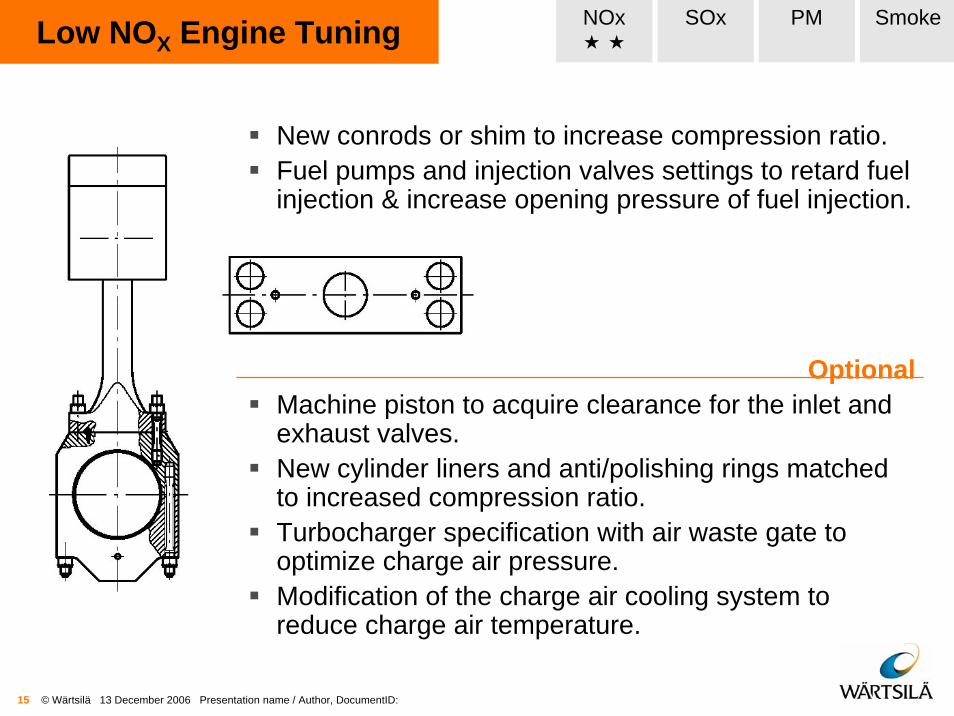
Low NOX Engine Tuning NOx SOx PM Smoke
OptionalMachine piston to acquire clearance for the inlet and exhaust valves.New cylinder liners and anti/polishing rings matched to increased compression ratio.Turbocharger specification with air waste gate to optimize charge air pressure.Modification of the charge air cooling system to reduce charge air temperature.
New conrods or shim to increase compression ratio.Fuel pumps and injection valves settings to retard fuel injection & increase opening pressure of fuel injection.

16 © Wärtsilä 13 December 2006 Presentation name / Author, DocumentID:
Diesel NOx Reduction
Main element of Dry Low NOx TechnologyAvailable for new built engine or as retrofit packages:
Late fuel injection start
High compression ratio
Optimized combustion chamber
Fuel system:• 4-stroke: Fuel rate shaping
(CR Technology)• 2-stroke: Flexible fuel injection
pattern (RT-flex Technology)
Valve system • 4-stroke: Early inlet valve closing
(Miller timing)• 2-stroke: Flexible (late) exhaust
valve closing (RT-flex Technology)
NOx SOx PM Smoke

17 © Wärtsilä 13 December 2006 Presentation name / Author, DocumentID:
Common Rail, 4-stroke
1) Injector
2) Accumulator
3) HP-pump
4) Shielded HP-pipes
5) Drive cam
NOx SOx PM Smoke

18 © Wärtsilä 13 December 2006 Presentation name / Author, DocumentID:
Fuel
Inje
ctio
n pr
essu
re (b
ar)
Engine load50% 100%0
500
1’000
1’500Common RailFree selection of fuel injection pressure
0%
Injection Pressure
Conventional mech. fuel injection- constant speed operation- decreasing injection pressure with
decreasing engine load
Conventional mech. fuel injection - propeller curve operation- decreasing injection pressure with
decreasing engine load and speed
NOx SOx PM Smoke

19 © Wärtsilä 13 December 2006 Presentation name / Author, DocumentID:
0
0.1
0.2
0.3
0.4
0.5
0.6
0.7
0.8
0.9
1
1.1
0 10 20 30 40 50 60 70 80 90 100
Engine load (%)
Filte
r Sm
oke
Num
ber F
SN
Common Rail, 4-stroke
Test results on 4-stroke Common Rail versus Conventional FIEVisible smoke typically at FSN > 0.3 -0.4
Conventional low speed Fuel Injection system4/stroke Common Rail
NOx SOx PM Smoke

20 © Wärtsilä 13 December 2006 Presentation name / Author, DocumentID:
Variable Inlet Valve Closing
Standard Miller Timing- Inlet Valve opens at crank angle 35° bTDC- Inlet Valve closes at crank angle 16°±1 bBDC
VIC Timing- Inlet Valve opens at crank angle 35° bTDC- Inlet Valve closes at crank angle 16°±1 aBDC
Delay in Inlet Valve Closing
Increase on air quantity & compression
pressure
Better combustion
process = LESS SMOKE
NoticeDelayed timing is actuated only below 50%loadOver 50% the system returns to standard Miller Timing
NOx SOx PM Smoke

21 © Wärtsilä 13 December 2006 Presentation name / Author, DocumentID:
Variable Inlet Valve Closing
After VIC
50%
50%
40-50% less smokelower smoke visibility point at about 30%below that point it will still reduce particles emissions by some 40%
NOx SOx PM Smoke
< 10% load

22 © Wärtsilä 13 December 2006 Presentation name / Author, DocumentID:
Primary Technologies, Wet

23 © Wärtsilä 13 December 2006 Presentation name / Author, DocumentID:
WETPAC -H
Evaporised water is partly re-condensingin the charge air coolerCompressor
Water injection 130-135 bar
Heat from cooling wateris reducing re-condensing
Saturated air40…70°C
Injected water mist is evaporated and hot air after compressor is cooled tosaturation point
Unevaporised watercaptured in WMC and re-circulated
NOx SOx PM Smoke
Scavenge Air Humidification

24 © Wärtsilä 13 December 2006 Presentation name / Author, DocumentID:
WETPAC -DWI NOx SOx PM Smoke
Direct Water Injection (DWI)

25 © Wärtsilä 13 December 2006 Presentation name / Author, DocumentID:
Secondary Technologies

26 © Wärtsilä 13 December 2006 Presentation name / Author, DocumentID:
Specific Catalytic Reducer NOx SOx PM Smoke
Nitrogen oxides (NOx) are deoxidized intonitrogen (N2) and water vapour (H2O) usingammonia or urea at a suitable temperature onthe surface of the catalyst. Process controlenables the amount of inactive ammonia in theflue gas to be kept low.
<- 4-stroke2-stroke ->

27 © Wärtsilä 13 December 2006 Presentation name / Author, DocumentID:
Seawater Scrubber (SWS)
SeawaterpH management with
engine cooling water
pH
pHpH
NaOH unit
Open loop is often met for seawater scrubber, the sulphur is neutralized by water alkalinity.
Optionally NaOH can be added to compensate drop in alkalinity for those vessels who navigate in different waters.
NOx SOx PM Smoke
Scrubber
ExhaustGas
WaterTreatment
Open loop

28 © Wärtsilä 13 December 2006 Presentation name / Author, DocumentID:
Fresh Water Scrubber (FWS)
Scrubber
pHpH
NaOH unitFresh or Greywater source
WaterTreatmentHeat
Exchanger
ExhaustGas
Seawater pH management with seawater
pH
Closed loop needs freshwater, to which NaOH is added for the neutralization of SOx.
NOx SOx PM Smoke
Closed loop

29 © Wärtsilä 13 December 2006 Presentation name / Author, DocumentID:
Trade Off and Costs

30 © Wärtsilä 13 December 2006 Presentation name / Author, DocumentID:
The NOX trade-off
Many measures taken to reduce particle emissionsalso tend to increase NOX emissions.
“… there are trade-offs with improving NOX emissions on other emissions such as particle matter and CO, as shown in Figure 4.2. Manufacturers must use a synergetic approach to gain a competitive edge by balancing the reduction of one type of engine emission against another, keeping in mind that fuel economy must not suffer.”
Source: CIMAC Guide to ExhaustEmission Control Options, 4-4
Em
issi
ons
(ppm
)
Specific Fuel Consumption (g/kWh)
NOX HCPMCO

31 © Wärtsilä 13 December 2006 Presentation name / Author, DocumentID:
NOX emissions versus BSFC
Many measures aimed at reducing NOX emissions also increase fuel consumption and the formation of particulates. Optimization of an engine’s emission levels therefore requires that all these factors are taken into account.

32 © Wärtsilä 13 December 2006 Presentation name / Author, DocumentID:
Cost to reduce emissions
Table 5.2: Costs of different emissions reduction methods

33 © Wärtsilä 13 December 2006 Presentation name / Author, DocumentID:
Conclusions

34 © Wärtsilä 13 December 2006 Presentation name / Author, DocumentID:
Considerations
• Low Sulphur Heavy Fuel Oil (LS-HFO) can be manufactured in refineries, but blending efficiency and stability is limited to 1,5%S
• Producing LS-HFO with sulphur content lower than 1,5% would require very heavy investment from fuel manufacturers
• These investments would be back charged as a fuel premium, getting the LS-HFO around +100$/ton compare to HFO
• Today low differential between LS-HFO and HFO (~25$/ton) is due to higher offering with lower than expected demand for SECA Baltic Sea
• In Nov 2007, SECA North Sea and English Channel will enter into force, volume demand will peak. LS Fuel premium is expected to be >60$/ton
Sources: CONCAWE review Spring 2006Lloyd’s Register Fairplay, New York 2006

35 © Wärtsilä 13 December 2006 Presentation name / Author, DocumentID:
Comments
• Emission reduction regulations ultimate goal is to reduce Air Emissions, especially along sea shore where community leaves, but not to limit technologies to achieve the required levels.
• Regulating fuel isn’t a holistic approach as:it will increase carbon foot print from land base production facilities and logistics chainsit only solves SOX while having low or no effect on PM, and other harmful particulates
• Primary & Secondary technologies combination can achieve high emission reduction, also on non-regulated particulates, while minimising investment on land base infrastructure and having no negative impact on carbon foot print
• Emission trading, already in force for CO (Nordic countries) and NOX (US land base facilities) is an enabler with proven effect on global emission reduction.
Sources: SEAaT studies andLloyd’s Register Fairplay Event London 2005

36 © Wärtsilä 13 December 2006 Presentation name / Author, DocumentID:
Total switch to Distillate workable?
©Ll
oyd’
s Li
st, N
ov 1
5th,
200
6


![COPY INSTITUTE FOR FLUID DYNAMICS - ntrs.nasa.gov · PDF fileEmission and Absorption Measurements ... the present data should directly benefit calculations of ... (T) [l - e ] before](https://static.documents.pub/doc/80x56/5a78f8307f8b9a523d8b5469/copy-institute-for-fluid-dynamics-ntrsnasagov-and-absorption-measurements-.jpg)


