ETSI EN 301 704 V7.2.1 (2000-04) European Standard (Telecommunications series) Digital cellular telecommunications system (Phase 2+); Adaptive Multi-Rate (AMR) speech transcoding (GSM 06.90 version 7.2.1 Release 1998) GLOBAL SYSTEM FOR MOBILE COMMUNICATIONS R
Transcript
ETSI EN 301 704 V7.2.1 (2000-04)European Standard (Telecommunications series)
Digital cellular telecommunications system (Phase 2+);Adaptive Multi-Rate (AMR) speech transcoding
(GSM 06.90 version 7.2.1 Release 1998)
GLOBAL SYSTEM FORMOBILE COMMUNICATIONS
R
ETSI
ETSI EN 301 704 V7.2.1 (2000-04)2(GSM 06.90 version 7.2.1 Release 1998)
Global System for Mobile communication (GSM),speech, AMR
ETSI
650 Route des LuciolesF-06921 Sophia Antipolis Cedex - FRANCE
Tel.: +33 4 92 94 42 00 Fax: +33 4 93 65 47 16
Siret N° 348 623 562 00017 - NAF 742 CAssociation à but non lucratif enregistrée à laSous-Préfecture de Grasse (06) N° 7803/88
Important notice
Individual copies of the present document can be downloaded from:http://www.etsi.org
The present document may be made available in more than one electronic version or in print. In any case of existing orperceived difference in contents between such versions, the reference version is the Portable Document Format (PDF).
In case of dispute, the reference shall be the printing on ETSI printers of the PDF version kept on a specific networkdrive within ETSI Secretariat.
Users of the present document should be aware that the document may be subject to revision or change of status.Information on the current status of this and other ETSI documents is available at http://www.etsi.org/tb/status/
If you find errors in the present document, send your comment to:[email protected]
Copyright Notification
No part may be reproduced except as authorized by written permission.The copyright and the foregoing restriction extend to reproduction in all media.
4 Outline description.................................................................................................................................134.1 Functional description of audio parts ...............................................................................................................134.2 Preparation of speech samples..........................................................................................................................144.2.1 PCM format conversion..............................................................................................................................144.3 Principles of the GSM adaptive multi-rate speech encoder ..............................................................................144.4 Principles of the GSM adaptive multi-rate speech decoder..............................................................................164.5 Sequence and subjective importance of encoded parameters ...........................................................................17
5 Functional description of the encoder....................................................................................................175.1 Pre-processing (all modes) ...............................................................................................................................175.2 Linear prediction analysis and quantization .....................................................................................................175.2.1 Windowing and auto-correlation computation............................................................................................185.2.2 Levinson-Durbin algorithm (all modes)......................................................................................................195.2.3 LP to LSP conversion (all modes) ..............................................................................................................205.2.4 LSP to LP conversion (all modes) ..............................................................................................................215.2.5 Quantization of the LSP coefficients ..........................................................................................................225.2.6 Interpolation of the LSPs ............................................................................................................................235.2.7 Monitoring resonance in the LPC spectrum (all modes).............................................................................245.3 Open-loop pitch analysis ..................................................................................................................................255.4 Impulse response computation (all modes).......................................................................................................285.5 Target signal computation (all modes) .............................................................................................................285.6 Adaptive codebook...........................................................................................................................................285.6.1 Adaptive codebook search ..........................................................................................................................285.6.2 Adaptive codebook gain control (all modes) ..............................................................................................325.7 Algebraic codebook..........................................................................................................................................335.7.1 Algebraic codebook structure .....................................................................................................................335.7.2 Algebraic codebook search.........................................................................................................................355.8 Quantization of the adaptive and fixed codebook gains ...................................................................................395.8.1 Adaptive codebook gain limitation in quantization ....................................................................................395.8.2 Quantization of codebook gains..................................................................................................................395.8.3 Update past quantized adaptive codebook gain buffer (all modes).............................................................415.9 Memory update (all modes)..............................................................................................................................41
6 Functional description of the decoder....................................................................................................426.1 Decoding and speech synthesis ........................................................................................................................426.2 Post-processing.................................................................................................................................................456.2.1 Adaptive post-filtering (all modes) .............................................................................................................456.2.2 High-pass filtering and up-scaling (all modes) ...........................................................................................46
7 Detailed bit allocation of the adaptive multi-rate codec ........................................................................46
Annex A (informative): Document change history..............................................................................57
History ..............................................................................................................................................................58
ETSI
ETSI EN 301 704 V7.2.1 (2000-04)5(GSM 06.90 version 7.2.1 Release 1998)
Intellectual Property RightsIPRs essential or potentially essential to the present document may have been declared to ETSI. The informationpertaining to these essential IPRs, if any, is publicly available for ETSI members and non-members, and can be foundin SR 000 314: "Intellectual Property Rights (IPRs); Essential, or potentially Essential, IPRs notified to ETSI in respectof ETSI standards", which is available from the ETSI Secretariat. Latest updates are available on the ETSI Web server(http://www.etsi.org/ipr).
Pursuant to the ETSI IPR Policy, no investigation, including IPR searches, has been carried out by ETSI. No guaranteecan be given as to the existence of other IPRs not referenced in SR 000 314 (or the updates on the ETSI Web server)which are, or may be, or may become, essential to the present document.
ForewordThis European Standard (Telecommunications series) has been produced by the Special Mobile Group (SMG).
The present document describes the detailed mapping from input blocks of 160 speech samples in 13-bit uniform PCMformat to encoded blocks of 95, 103, 118, 134, 148, 159, 204, and 244 bits and from encoded blocks of 95, 103, 118,134, 148, 159, 204, and 244 bits to output blocks of 160 reconstructed speech samples within the digital cellulartelecommunications system.
The contents of the present document is subject to continuing work within SMG and may change following formal SMGapproval. Should SMG modify the contents of the present document it will be re-released with an identifying change ofrelease date and an increase in version number as follows:
Version 7.x.y
where:
7 indicates Release 1998 of GSM Phase 2+.
x the second digit is incremented for all changes of substance, i.e. technical enhancements, corrections, updates,etc.
y the third digit is incremented when editorial only changes have been incorporated in the specification.
National transposition dates
Date of adoption of this EN: 31 March 2000
Date of latest announcement of this EN (doa): 30 June 2000
Date of latest publication of new National Standardor endorsement of this EN (dop/e): 31 December 2000
Date of withdrawal of any conflicting National Standard (dow): 31 December 2000
ETSI EN 301 704 V7.2.1 (2000-04)6(GSM 06.90 version 7.2.1 Release 1998)
1 ScopeThe present document describes the detailed mapping from input blocks of 160 speech samples in 13-bit uniform PCMformat to encoded blocks of 95, 103, 118, 134, 148, 159, 204, and 244 bits and from encoded blocks of 95, 103, 118,134, 148, 159, 204, and 244 bits to output blocks of 160 reconstructed speech samples. The sampling rate is8 000 samples/s leading to a bit rate for the encoded bit stream of 4.75, 5.15, 5.90, 6.70, 7.40, 7.95, 10.2 or 12.2 kbit/s.The coding scheme for the multi-rate coding modes is the so-called Algebraic Code Excited Linear Prediction Coder,hereafter referred to as ACELP. The multi-rate ACELP coder is referred to as MR-ACELP.
In the case of discrepancy between the requirements described in the present document and the fixed pointcomputational description (ANSI-C code) of these requirements contained in GSM 06.73 [6], the description inGSM 06.73 [6] will prevail. The ANSI-C code is not described in the present document, see GSM 06.73 [6] for adescription of the ANSI-C code.
The transcoding procedure specified in the present document is applicable for the adaptive multi-rate full rate and halfrate speech traffic channels (TCH) in the GSM system.
In GSM 06.71 [5], a reference configuration for the speech transmission chain of the GSM adaptive multi-rate (AMR)system is shown. According to this reference configuration, the speech encoder takes its input as a 13-bit uniform PCMsignal either from the audio part of the Mobile Station or on the network side, from the PSTN via an 8-bit A-law orµ -law to 13-bit uniform PCM conversion. The encoded speech at the output of the speech encoder is delivered to a
channel encoder unit which is specified in GSM 05.03 [3]. In the receive direction, the inverse operations take place.
2 ReferencesThe following documents contain provisions which, through reference in this text, constitute provisions of the presentdocument.
• References are either specific (identified by date of publication, edition number, version number, etc.) ornon-specific.
• For a specific reference, subsequent revisions do not apply.
• For a non-specific reference, the latest version applies.
• A non-specific reference to an ETS shall also be taken to refer to later versions published as an EN with the samenumber.
• For this Release 1998 document, references to GSM documents are for Release 1998 versions (version 7.x.y).
[2] GSM 03.50: "Digital cellular telecommunications system (Phase 2+); Transmission planningaspects of the speech service in the GSM Public Land Mobile Network (PLMN) system".
3.1 DefinitionsFor the purposes of the present document, the following terms and definitions apply.
adaptive codebook: The adaptive codebook contains excitation vectors that are adapted for every subframe. Theadaptive codebook is derived from the long-term filter state. The lag value can be viewed as an index into the adaptivecodebook.
adaptive postfilter: This filter is applied to the output of the short-term synthesis filter to enhance the perceptual qualityof the reconstructed speech. In the adaptive multi-rate codec, the adaptive postfilter is a cascade of two filters: a formantpostfilter and a tilt compensation filter.
Adaptive Multi-Rate (AMR) codec: Speech and channel codec capable of operating at gross bit-rates of 11.4 kbit/s(“half-rate”) and 22.8 kbit/s (“full-rate”). In addition, the codec may operate at various combinations of speech andchannel coding (codec mode) bit-rates for each channel mode.
algebraic codebook: A fixed codebook where algebraic code is used to populate the excitation vectors (innovationvectors). The excitation contains a small number of nonzero pulses with predefined interlaced sets of positions.
AMR handover: Handover between the FR and HR channel modes to optimise AMR operation.
anti-sparseness processing: An adaptive post-processing procedure applied to the fixed codebook vector in order toreduce perceptual artifacts from a sparse fixed codebook vector.
channel mode: Half-rate or full-rate operation.
channel mode adaptation: The control and selection of the (FR or HR) channel mode.
channel repacking: Repacking of HR (and FR) radio channels of a given radio cell to achieve higher capacity withinthe cell.
closed-loop pitch analysis: This is the adaptive codebook search, i.e., a process of estimating the pitch (lag) value fromthe weighted input speech and the long term filter state. In the closed-loop search, the lag is searched using errorminimization loop (analysis-by-synthesis). In the adaptive multi-rate codec, closed-loop pitch search is performed forevery subframe.
codec mode: For a given channel mode, the bit partitioning between the speech and channel codecs.
codec mode adaptation: The control and selection of the codec mode bit-rates. Normally, implies no change to thechannel mode.
direct form coefficients: One of the formats for storing the short term filter parameters. In the adaptive multi-ratecodec, all filters which are used to modify speech samples use direct form coefficients.
fixed codebook: The fixed codebook contains excitation vectors for speech synthesis filters. The contents of thecodebook are non-adaptive (i.e., fixed). In the adaptive multi-rate codec, the fixed codebook is implemented using analgebraic codebook.
fractional lags: A set of lag values having sub-sample resolution. In the adaptive multi-rate codec a sub-sampleresolution of 1/6th or 1/3rd of a sample is used.
full-rate (FR): Full-rate channel or channel mode.
frame: A time interval equal to 20 ms (160 samples at an 8 kHz sampling rate).
ETSI
ETSI EN 301 704 V7.2.1 (2000-04)8(GSM 06.90 version 7.2.1 Release 1998)
gross bit-rate: The bit-rate of the channel mode selected (22.8 kbs or 11.4 kbs).
half-rate (HR): Half-rate channel or channel mode.
in-band signalling: Signalling for DTX, Link Control, Channel and codec mode modification, etc. carried within thetraffic channel.
integer lags: A set of lag values having whole sample resolution.
interpolating filter: An FIR filter used to produce an estimate of subsample resolution samples, given an input sampledwith integer sample resolution.
inverse filter: This filter removes the short term correlation from the speech signal. The filter models an inversefrequency response of the vocal tract.
lag: The long term filter delay. This is typically the true pitch period, or its multiple or sub-multiple.
Line Spectral Frequencies: (see Line Spectral Pair).
Line Spectral Pair: Transformation of LPC parameters. Line Spectral Pairs are obtained by decomposing the inversefilter transfer function A(z) to a set of two transfer functions, one having even symmetry and the other having oddsymmetry. The Line Spectral Pairs (also called as Line Spectral Frequencies) are the roots of these polynomials on thez-unit circle.
LP analysis window: For each frame, the short term filter coefficients are computed using the high pass filtered speechsamples within the analysis window. In the adaptive multi-rate codec, the length of the analysis window is always 240samples. For each frame, two asymmetric windows are used to generate two sets of LP coefficient in the 12,2 kbit/smode. For the other modes, only a single asymmetric window is used to generate a single set of LP coefficients. In the12,2 kbit/s mode, no samples of the future frames are used (no lookahead). The other modes use a 5 ms lookahead.
LP coefficients: Linear Prediction (LP) coefficients (also referred as Linear Predictive Coding (LPC) coefficients) is ageneric descriptive term for the short term filter coefficients.
mode: When used alone, refers to the source codec mode, i.e., to one of the source codecs employed in the AMR codec.(See also codec mode and channel mode.)
open-loop pitch search: A process of estimating the near optimal lag directly from the weighted speech input. This isdone to simplify the pitch analysis and confine the closed-loop pitch search to a small number of lags around theopen-loop estimated lags. In the adaptive multi-rate codec, an open-loop pitch search is performed in every othersubframe.
out-of-band signalling: Signalling on the GSM control channels to support link control.
residual: The output signal resulting from an inverse filtering operation.
short term synthesis filter: This filter introduces, into the excitation signal, short term correlation which models theimpulse response of the vocal tract.
perceptual weighting filter: This filter is employed in the analysis-by-synthesis search of the codebooks. The filterexploits the noise masking properties of the formants (vocal tract resonances) by weighting the error less in regions nearthe formant frequencies and more in regions away from them.
subframe: A time interval equal to 5 ms (40 samples at 8 kHz sampling rate).
vector quantization: A method of grouping several parameters into a vector and quantizing them simultaneously.
zero input response: The output of a filter due to past inputs, i.e. due to the present state of the filter, given that aninput of zeros is applied.
zero state response: The output of a filter due to the present input, given that no past inputs have been applied, i.e.,given that the state information in the filter is all zeroes.
ETSI
ETSI EN 301 704 V7.2.1 (2000-04)9(GSM 06.90 version 7.2.1 Release 1998)
3.2 SymbolsFor the purposes of the present document, the following symbols apply:
( )A z The inverse filter with unquantized coefficients
( )�A z The inverse filter with quantized coefficients
( )( )
H zA z
= 1�
The speech synthesis filter with quantized coefficients
ai The unquantized linear prediction parameters (direct form coefficients)
�ai The quantified linear prediction parametersm The order of the LP model
1B z( )
The long-term synthesis filter
( )W z The perceptual weighting filter (unquantized coefficients)
γ γ1 2, The perceptual weighting factors
F zE ( ) Adaptive pre-filter
T The integer pitch lag nearest to the closed-loop fractional pitch lag of the subframeβ The adaptive pre-filter coefficient (the quantified pitch gain)
H zA z
A zf
n
d
( )�( / )�( / )
= γγ
The formant postfilter
γn Control coefficient for the amount of the formant post-filtering
γd Control coefficient for the amount of the formant post-filtering
( )H zt Tilt compensation filter
γ t Control coefficient for the amount of the tilt compensation filtering
µ γ= t k1' A tilt factor, with k1' being the first reflection coefficient
( )h nf The truncated impulse response of the formant postfilter
Lh The length of ( )h nf
r ih ( ) The auto-correlations of ( )h nf
( )�A z nγ The inverse filter (numerator) part of the formant postfilter
( )1 �A z dγ The synthesis filter (denominator) part of the formant postfilter
( )�r n The residual signal of the inverse filter ( )�A z nγ( )h nt Impulse response of the tilt compensation filter
β sc n( ) The AGC-controlled gain scaling factor of the adaptive postfilter
α The AGC factor of the adaptive postfilter
( )H zh1 Pre-processing high-pass filter
w nI ( ) , w nII ( ) LP analysis windows
L I1( ) Length of the first part of the LP analysis window w nI ( )
L I2
( ) Length of the second part of the LP analysis window w nI ( )
L II1( ) Length of the first part of the LP analysis window w nII ( )
L II2
( ) Length of the second part of the LP analysis window w nII ( )r kac ( ) The auto-correlations of the windowed speech s n' ( )
( )w ilag Lag window for the auto-correlations (60 Hz bandwidth expansion)
ETSI
ETSI EN 301 704 V7.2.1 (2000-04)10(GSM 06.90 version 7.2.1 Release 1998)
f0 The bandwidth expansion in Hz
f s The sampling frequency in Hz
r kac' ( )The modified (bandwidth expanded) auto-correlations
( )E iLD The prediction error in the ith iteration of the Levinson algorithm
ki The ith reflection coefficient
a ji( ) The jth direct form coefficient in the ith iteration of the Levinson algorithm
( )′F z1 Symmetric LSF polynomial
( )′F z2 Antisymmetric LSF polynomial
( )F z1 Polynomial ( )′F z1 with root z = −1 eliminated
( )F z2 Polynomial ( )′F z2 with root z = 1 eliminated
qi The line spectral pairs (LSPs) in the cosine domainq An LSP vector in the cosine domain
�( )qin The quantified LSP vector at the ith subframe of the frame n
ωi The line spectral frequencies (LSFs)
T xm ( ) A m th order Chebyshev polynomial
f i f i1 2( ), ( ) The coefficients of the polynomials F z1( ) and F z2( )
f i f i1 2' '( ), ( ) The coefficients of the polynomials ( )′F z1 and ( )′F z2
f i( ) The coefficients of either ( )F z1 or ( )F z2
( )C x Sum polynomial of the Chebyshev polynomialsx Cosine of angular frequency ωλ k Recursion coefficients for the Chebyshev polynomial evaluation
fi The line spectral frequencies (LSFs) in Hz
[ ]f t f f f= 1 2 10� The vector representation of the LSFs in Hz
( )z( )1 n , ( )z( )2 n The mean-removed LSF vectors at frame n
( )r ( )1 n , ( )r ( )2 n The LSF prediction residual vectors at frame np( )n The predicted LSF vector at frame n
( )�( )r 2 1n − The quantified second residual vector at the past frame�f k The quantified LSF vector at quantization index kELSP The LSP quantization error
w ii , , , ,=1 10� LSP-quantization weighting factors
di The distance between the line spectral frequencies fi+1 and fi−1
( )h n The impulse response of the weighted synthesis filterOk The correlation maximum of open-loop pitch analysis at delay k
O iti, , ,=1 3� The correlation maxima at delays t ii , , ,= 1 3�
( )M t ii i, , , ,=1 3� The normalized correlation maxima Mi and the corresponding delays t ii , , ,= 1 3�
H z W zA z
A z A z( ) ( )
( / )�( ) ( / )
= γγ
1
2
The weighted synthesis filter
( )A z γ1 The numerator of the perceptual weighting filter
( )1 2A z γ The denominator of the perceptual weighting filter
ETSI
ETSI EN 301 704 V7.2.1 (2000-04)11(GSM 06.90 version 7.2.1 Release 1998)
T1 The integer nearest to the fractional pitch lag of the previous (1st or 3rd) subframe
s n' ( ) The windowed speech signal
( )s nw The weighted speech signal
( )�s n Reconstructed speech signal( )� ′s n The gain-scaled post-filtered signal( )�s nf Post-filtered speech signal (before scaling)
( )x n The target signal for adaptive codebook search
( )x n2 , x2t The target signal for algebraic codebook search
res nLP ( ) The LP residual signal
( )c n The fixed codebook vector( )v n The adaptive codebook vector
y n v n h n( ) = ( ) ( )∗ The filtered adaptive codebook vector
( )y nk The past filtered excitation
( )u n The excitation signal
( )�u n The emphasized adaptive codebook vector
�' ( )u n The gain-scaled emphasized excitation signal
Top The best open-loop lag
tmin Minimum lag search value
tmax Maximum lag search value
( )R k Correlation term to be maximized in the adaptive codebook search
b24 The FIR filter for interpolating the normalized correlation term ( )R k
( )R k t The interpolated value of ( )R k for the integer delay k and fraction t
b60 The FIR filter for interpolating the past excitation signal ( )u n to yield the adaptive codebook
vector ( )v n
Ak Correlation term to be maximized in the algebraic codebook search at index k
Ck The correlation in the numerator of Ak at index k
EDk The energy in the denominator of Ak at index k
d H x= t2 The correlation between the target signal ( )x n2 and the impulse response ( )h n , i.e., backward
filtered target
H The lower triangular Toepliz convolution matrix with diagonal ( )h 0 and lower diagonals
( ) ( )h h1 39, ,�
Φ = H Ht The matrix of correlations of ( )h n
d n( ) The elements of the vector dφ( , )i j The elements of the symmetric matrix Φck The innovation vector
C The correlation in the numerator of Ak
mi The position of the ith pulse
ϑ i The amplitude of the ith pulse
N p The number of pulses in the fixed codebook excitation
ED The energy in the denominator of Ak
ETSI
ETSI EN 301 704 V7.2.1 (2000-04)12(GSM 06.90 version 7.2.1 Release 1998)
( )res nLTP The normalized long-term prediction residual
( )b n The signal used for presetting the signs in algebraic codebook search( )s nb The sign signal for the algebraic codebook search
( )′d n Sign extended backward filtered target
φ' ( , )i j The modified elements of the matrix Φ , including sign information
zt , ( )z n The fixed codebook vector convolved with ( )h n
( )E n The mean-removed innovation energy (in dB)
E The mean of the innovation energy
( )~E n The predicted energy
[ ]b b b b1 2 3 4 The MA prediction coefficients
( )�R k The quantified prediction error at subframe kEI The mean innovation energy
R n( ) The prediction error of the fixed-codebook gain quantization
EQ The quantization error of the fixed-codebook gain quantization
e n( ) The states of the synthesis filter ( )1 �A z( )e nw The perceptually weighted error of the analysis-by-synthesis search
η The gain scaling factor for the emphasized excitation
gc The fixed-codebook gain
′gc The predicted fixed-codebook gain
�gc The quantified fixed codebook gain
g p The adaptive codebook gain
�g p The quantified adaptive codebook gain
γ gc c cg g= ′ A correction factor between the gain gc and the estimated one ′gc
�γ gc The optimum value for γ gc
γ sc Gain scaling factor
3.3 AbbreviationsFor the purposes of the present document, the following abbreviations apply. Further GSM related abbreviations may befound in GSM 01.04 [1].
ACELP Algebraic Code Excited Linear PredictionAGC Adaptive Gain ControlAMR Adaptive Multi-RateCELP Code Excited Linear PredictionEFR Enhanced Full RateFIR Finite Impulse ResponseFR Full RateHR Half RateISPP Interleaved Single-Pulse PermutationLP Linear PredictionLPC Linear Predictive CodingLSF Line Spectral FrequencyLSP Line Spectral PairLTP Long Term Predictor (or Long Term Prediction)MA Moving Average
ETSI
ETSI EN 301 704 V7.2.1 (2000-04)13(GSM 06.90 version 7.2.1 Release 1998)
4 Outline descriptionThe present document is structured as follows:
Section 4.1 contains a functional description of the audio parts including the A/D and D/A functions. Section 4.2describes the conversion between 13-bit uniform and 8-bit A-law or µ -law samples. Sections 4.3 and 4.4 present a
simplified description of the principles of the AMR codec encoding and decoding process respectively. In subclause 4.5,the sequence and subjective importance of encoded parameters are given.
Section 5 presents the functional description of the AMR codec encoding, whereas clause 6 describes the decodingprocedures. In section 7, the detailed bit allocation of the AMR codec is tabulated.
4.1 Functional description of audio partsThe analogue-to-digital and digital-to-analogue conversion will in principle comprise the following elements:
1) Analogue to uniform digital PCM
− microphone;
− input level adjustment device;
− input anti-aliasing filter;
− sample-hold device sampling at 8 kHz;
− analogue−to−uniform digital conversion to 13−bit representation.
The uniform format shall be represented in two's complement.
2) Uniform digital PCM to analogue
− conversion from 13−bit/8 kHz uniform PCM to analogue;
− a hold device;
− reconstruction filter including x/sin( x ) correction;
− output level adjustment device;
− earphone or loudspeaker.
In the terminal equipment, the A/D function may be achieved either
− by direct conversion to 13-bit uniform PCM format;
− or by conversion to 8-bit A-law or µ -law compounded format, based on a standard A-law or µ -law codec/filter
according to ITU-T Recommendations G.711 [8] and G.714, followed by the 8-bit to 13-bit conversion asspecified in subclause 4.2.1.
For the D/A operation, the inverse operations take place.
In the latter case it should be noted that the specifications in ITU-T G.714 (superseded by G.712) are concerned withPCM equipment located in the central parts of the network. When used in the terminal equipment, the present documentdoes not on its own ensure sufficient out-of-band attenuation. The specification of out-of-band signals is defined inGSM 03.50 [2] in clause 2.
ETSI
ETSI EN 301 704 V7.2.1 (2000-04)14(GSM 06.90 version 7.2.1 Release 1998)
4.2 Preparation of speech samplesThe encoder is fed with data comprising of samples with a resolution of 13 bits left justified in a 16-bit word. The threeleast significant bits are set to '0'. The decoder outputs data in the same format. Outside the speech codec furtherprocessing must be applied if the traffic data occurs in a different representation.
4.2.1 PCM format conversion
The conversion between 8-bit A-Law or µ -law compressed data and linear data with 13-bit resolution at the speech
encoder input shall be as defined in ITU-T Rec. G.711 [8].
ITU-T Rec. G.711 [8] specifies the A-Law or µ -law to linear conversion and vice versa by providing table entries.
Examples on how to perform the conversion by fixed-point arithmetic can be found in ITU-T Rec. G.726 [9]. Section4.2.1 of G.726 [9] describes A-Law or µ -law to linear expansion and subclause 4.2.8 of G.726 [9] provides a solution
for linear to A-Law or µ -law compression.
4.3 Principles of the GSM adaptive multi-rate speech encoderThe AMR codec uses eight source codecs with bit-rates of 12.2, 10.2, 7.95, 7.40, 6.70, 5.90, 5.15 and 4.75 kbit/s.
The codec is based on the code-excited linear predictive (CELP) coding model. A 10th order linear prediction (LP), orshort-term, synthesis filter is used which is given by:
( )( )H z
A z a zii
i
m= =+ −
=�
1 1
11
��
, (1)
where � , , , ,a i mi =1� are the (quantified) linear prediction (LP) parameters, and m =10 is the predictor order. The
long-term, or pitch, synthesis filter is given by:
( )1 1
1B z g zpT=
− − , (2)
where T is the pitch delay and gp is the pitch gain. The pitch synthesis filter is implemented using the so-called
adaptive codebook approach.
The CELP speech synthesis model is shown in figure 2. In this model, the excitation signal at the input of the short-termLP synthesis filter is constructed by adding two excitation vectors from adaptive and fixed (innovative) codebooks. Thespeech is synthesized by feeding the two properly chosen vectors from these codebooks through the short-term synthesisfilter. The optimum excitation sequence in a codebook is chosen using an analysis-by-synthesis search procedure inwhich the error between the original and synthesized speech is minimized according to a perceptually weighteddistortion measure.
The perceptual weighting filter used in the analysis-by-synthesis search technique is given by:
( ) ( )( )W z
A z
A z=
γγ
1
2
, (3)
where ( )A z is the unquantized LP filter and 0 12 1< < ≤γ γ are the perceptual weighting factors. The values
γ1 0 9= . (for the 12.2 and 10.2 kbit/s mode) or 94.01 =γ (for all other modes) and γ2 0 6= . are used. The
weighting filter uses the unquantized LP parameters.
The coder operates on speech frames of 20 ms corresponding to 160 samples at the sampling frequency of 8 000sample/s. At each 160 speech samples, the speech signal is analysed to extract the parameters of the CELP model (LPfilter coefficients, adaptive and fixed codebooks' indices and gains). These parameters are encoded and transmitted. At
ETSI
ETSI EN 301 704 V7.2.1 (2000-04)15(GSM 06.90 version 7.2.1 Release 1998)
the decoder, these parameters are decoded and speech is synthesized by filtering the reconstructed excitation signalthrough the LP synthesis filter.
The signal flow at the encoder is shown in figure 3. LP analysis is performed twice per frame for the 12.2 kbit/s modeand once for the other modes. For the 12.2 kbit/s mode, the two sets of LP parameters are converted to line spectrumpairs (LSP) and jointly quantized using split matrix quantization (SMQ) with 38 bits. For the other modes, the single setof LP parameters is converted to line spectrum pairs (LSP) and vector quantized using split vector quantization (SVQ).The speech frame is divided into 4 subframes of 5 ms each (40 samples). The adaptive and fixed codebook parametersare transmitted every subframe. The quantized and unquantized LP parameters or their interpolated versions are useddepending on the subframe. An open-loop pitch lag is estimated in every other subframe (except for the 5.15 and 4.75kbit/s modes for which it is done once per frame) based on the perceptually weighted speech signal.
Then the following operations are repeated for each subframe:
The target signal ( )x n is computed by filtering the LP residual through the weighted synthesis filter
( ) ( )W z H z with the initial states of the filters having been updated by filtering the error between LP residualand excitation (this is equivalent to the common approach of subtracting the zero input response of the weightedsynthesis filter from the weighted speech signal).
The impulse response, ( )h n of the weighted synthesis filter is computed.
Closed-loop pitch analysis is then performed (to find the pitch lag and gain), using the target ( )x n and impulse
response ( )h n , by searching around the open-loop pitch lag. Fractional pitch with 1/6th or 1/3rd of a sampleresolution (depending on the mode) is used.
The target signal ( )x n is updated by removing the adaptive codebook contribution (filtered adaptive
codevector), and this new target, ( )x n2 , is used in the fixed algebraic codebook search (to find the optimum
innovation).
The gains of the adaptive and fixed codebook are scalar quantified with 4 and 5 bits respectively or vectorquantified with 6-7 bits (with moving average (MA) prediction applied to the fixed codebook gain).
Finally, the filter memories are updated (using the determined excitation signal) for finding the target signal inthe next subframe.
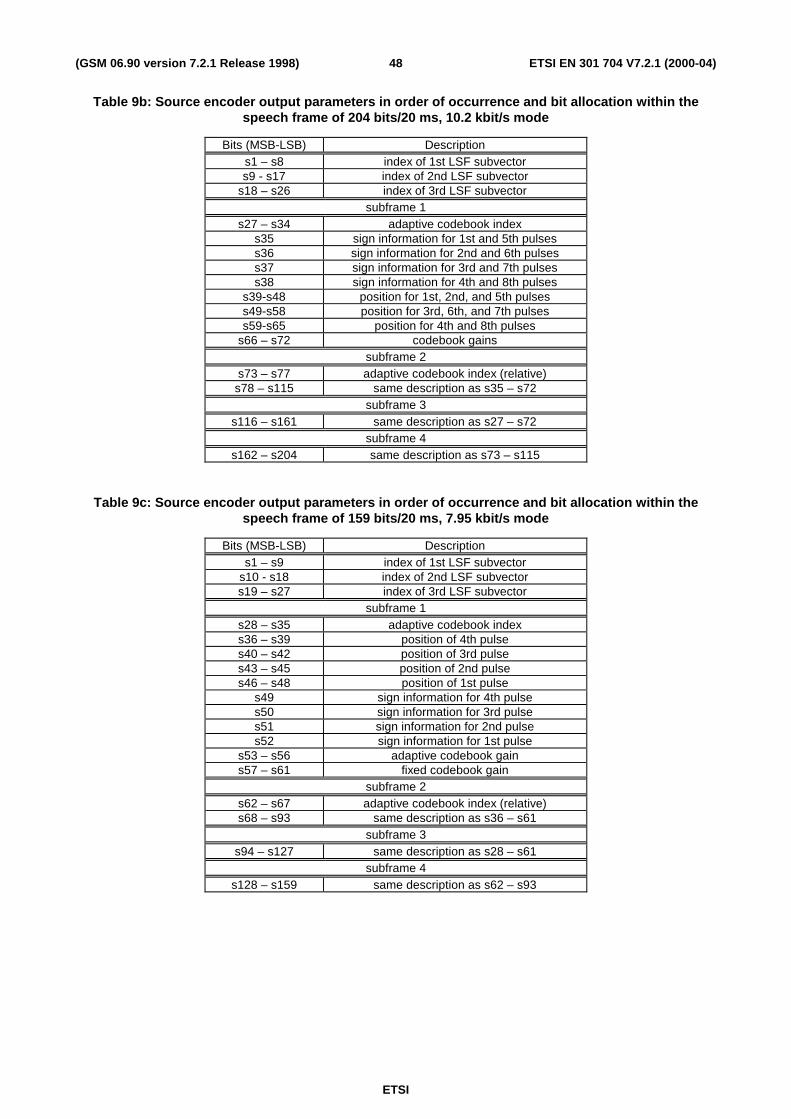
The bit allocation of the AMR codec modes is shown in table 1. In each 20 ms speech frame, 95, 103, 118, 134, 148,159, 204 or 244 bits are produced, corresponding to a bit-rate of 4.75, 5.15, 5.90, 6.70, 7.40, 7.95, 10.2 or 12.2 kbit/s.More detailed bit allocation among the codec parameters is given in tables 9a-9h. Note that the most significant bits(MSB) are always sent first.
ETSI
ETSI EN 301 704 V7.2.1 (2000-04)16(GSM 06.90 version 7.2.1 Release 1998)
Table 1: Bit allocation of the AMR coding algorithm for 20 ms frame
4.4 Principles of the GSM adaptive multi-rate speech decoderThe signal flow at the decoder is shown in figure 4. At the decoder, based on the chosen mode, the transmitted indicesare extracted from the received bitstream. The indices are decoded to obtain the coder parameters at each transmissionframe. These parameters are the LSP vectors, the fractional pitch lags, the innovative codevectors, and the pitch andinnovative gains. The LSP vectors are converted to the LP filter coefficients and interpolated to obtain LP filters at eachsubframe. Then, at each 40-sample subframe:
- the excitation is constructed by adding the adaptive and innovative codevectors scaled by their respective gains;
- the speech is reconstructed by filtering the excitation through the LP synthesis filter.
ETSI
ETSI EN 301 704 V7.2.1 (2000-04)17(GSM 06.90 version 7.2.1 Release 1998)
Finally, the reconstructed speech signal is passed through an adaptive postfilter.
4.5 Sequence and subjective importance of encodedparameters
The encoder will produce the output information in a unique sequence and format, and the decoder must receive thesame information in the same way. In table 9a-9h, the sequence of output bits and the bit allocation for each parameter isshown.
The different parameters of the encoded speech and their individual bits have unequal importance with respect tosubjective quality. Before being submitted to the channel encoding function the bits have to be rearranged in thesequence of importance as given in 05.03 [3].
5 Functional description of the encoderIn this clause, the different functions of the encoder represented in figure 3 are described.
5.1 Pre-processing (all modes)Two pre-processing functions are applied prior to the encoding process: high-pass filtering and signal down-scaling.
Down-scaling consists of dividing the input by a factor of 2 to reduce the possibility of overflows in the fixed-pointimplementation.
The high-pass filter serves as a precaution against undesired low frequency components. A filter with a cut off frequencyof 80 Hz is used, and it is given by:
21
21
1 911376953.0906005859.11
927246903.08544941.1927246093.0)( −−
−−
+−+−=
zz
zzzH h . (4)
Down-scaling and high-pass filtering are combined by dividing the coefficients at the numerator of ( )H zh1 by 2.
5.2 Linear prediction analysis and quantization
12.2 kbit/s mode
Short-term prediction, or linear prediction (LP), analysis is performed twice per speech frame using the auto-correlationapproach with 30 ms asymmetric windows. No lookahead is used in the auto-correlation computation.
The auto-correlations of windowed speech are converted to the LP coefficients using the Levinson-Durbin algorithm.Then the LP coefficients are transformed to the Line Spectral Pair (LSP) domain for quantization and interpolationpurposes. The interpolated quantified and unquantized filter coefficients are converted back to the LP filter coefficients(to construct the synthesis and weighting filters at each subframe).
Short-term prediction, or linear prediction (LP), analysis is performed once per speech frame using the auto-correlationapproach with 30 ms asymmetric windows. A lookahead of 40 samples (5 ms) is used in the auto-correlationcomputation.
The auto-correlations of windowed speech are converted to the LP coefficients using the Levinson-Durbin algorithm.Then the LP coefficients are transformed to the Line Spectral Pair (LSP) domain for quantization and interpolationpurposes. The interpolated quantified and unquantized filter coefficients are converted back to the LP filter coefficients(to construct the synthesis and weighting filters at each subframe).
ETSI
ETSI EN 301 704 V7.2.1 (2000-04)18(GSM 06.90 version 7.2.1 Release 1998)
5.2.1 Windowing and auto-correlation computation
12.2 kbit/s mode
LP analysis is performed twice per frame using two different asymmetric windows. The first window has its weightconcentrated at the second subframe and it consists of two halves of Hamming windows with different sizes. Thewindow is given by:
w n
n
Ln L
n L
Ln L L L
I
II
I
II I I
( )
. .46 , , , ,
. .46( )
, , , .
( )( )
( )
( )( ) ( ) ( )
=−
−�
��
�
�� = −
+ −−
�
��
�
�� = + −
�
�
0 54 01
0 1
0 54 01
1
11
1
21 1 2
cos
cos
π
π
�
�
(5)
The values L I1 160( ) = and L I
2 80( ) = are used. The second window has its weight concentrated at the fourth
subframe and it consists of two parts: the first part is half a Hamming window and the second part is a quarter of acosine function cycle. The window is given by:
w n
n
Ln L
n L
Ln L L L
II
IIII
II
IIII II II
( )
. .46 , , , ,
( ), , ,
( )( )
( )
( )( ) ( ) ( )
=−
−�
��
�
�� = −
−−
�
��
�
�� = + −
�
�
0 54 02
2 10 1
2
4 11
11
1
21 1 2
cos
cos
π
π
�
�
(6)
where the values L II1 232( ) = and L II
2 8( ) = are used.
Note that both LP analyses are performed on the same set of speech samples. The windows are applied to 80 samplesfrom past speech frame in addition to the 160 samples of the present speech frame. No samples from future frames areused (no lookahead). A diagram of the two LP analysis windows is depicted below.
20 ms5 ms
frame (160 samples) sub frame(40 samples)
frame n-1 frame n
t
Iw (n)
IIw (n)
Figure 1: LP analysis windows
The auto-correlations of the windowed speech ( )′ =s n n, ,0 239� , are computed by:
ETSI
ETSI EN 301 704 V7.2.1 (2000-04)19(GSM 06.90 version 7.2.1 Release 1998)
r k s n s n k kacn k
( ) ' ( ) ' ( ) , , , ,= − ==�239
0 10� (7)
and a 60 Hz bandwidth expansion is used by lag windowing the auto-correlations using the window:
( )w if i
filag
s= −
�
��
�
��
�
�
�
��
=exp , ,1
2
21 100
2π� , (8)
where f0 60= Hz is the bandwidth expansion and f s = 8000 Hz is the sampling frequency. Further, rac ( )0 is
multiplied by the white noise correction factor 1.0001 which is equivalent to adding a noise floor at -40 dB.
LP analysis is performed once per frame using an asymmetric window. The window has its weight concentrated at thefourth subframe and it consists of two parts: the first part is half a Hamming window and the second part is a quarter of a
cosine function cycle. The window is given by equation (6) where the values 2001 =L and 402 =L are used.
The auto-correlations of the windowed speech ( )′ =s n n, ,0 239� , are computed by equation (7) and a 60 Hz
bandwidth expansion is used by lag windowing the auto-correlations using the window of equation (8). Further, rac ( )0is multiplied by the white noise correction factor 1.0001 which is equivalent to adding a noise floor at -40 dB.
5.2.2 Levinson-Durbin algorithm (all modes)
The modified auto-correlations r rac ac' ( ) . ( )0 1 0001 0= and r k r k w k kac ac lag' ( ) ( ) ( ), , ,= =1 10� are used to
obtain the direct form LP filter coefficients a kk , , , ,=1 10� by solving the set of equations.
( )a r i k r i ik ack
ac' ' ( ) , , , .− = − ==�
1
10
1 10� (9)
The set of equations in (9) is solved using the Levinson-Durbin algorithm. This algorithm uses the following recursion:
[ ]
E ria
k a r i j E i
a kj i
a a k a
E i k E i
LD ac
i
i ji
acj
iLD
ii
i
ji
ji
i i ji
LD i LD
( ) ' ( )
' ( ) / ( )
( ) ( ) ( )
( )
( )
( )
( ) ( ) ( )
0 01 10
1
1
1 1
1 1
01
10
1
1 1
2
==
=
= − − −
== −
= +
= − −
−
−=−
−−−
�
for to do
for to do
end
end
The final solution is given as a a jj j= =( ) , , ,10 1 10� .
The LP filter coefficients are converted to the line spectral pair (LSP) representation for quantization and interpolationpurposes. The conversions to the LSP domain and back to the LP filter coefficient domain are described in the nextclause.
ETSI
ETSI EN 301 704 V7.2.1 (2000-04)20(GSM 06.90 version 7.2.1 Release 1998)
5.2.3 LP to LSP conversion (all modes)
The LP filter coefficients a kk , , ,=1 10� , are converted to the line spectral pair (LSP) representation for quantization
and interpolation purposes. For a 10th order LP filter, the LSPs are defined as the roots of the sum and differencepolynomials:
( ) ( ) ( )′ = + − −F z A z z A z111 1 (10)
and
( ) ( ) ( )′ = − − −F z A z z A z211 1 , (11)
respectively. The polynomial ( )′F z1 and ( )′F z2 are symmetric and anti-symmetric, respectively. It can be proven that
all roots of these polynomials are on the unit circle and they alternate each other. ( )′F z1 has a root z = −1 (ω π= )
and ( )′F z2 has a root z = 1 (ω = 0 ). To eliminate these two roots, we define the new polynomials:
( ) ( ) ( )F z F z z1 111= ′ + − (12)
and
( ) ( ) ( )F z F z z2 211= ′ − − (13)
Each polynomial has 5 conjugate roots on the unit circle ( )e j i± ω , therefore, the polynomials can be written as
( ) ( )F z q z zii
11 2
1 3 91 2= − +− −
=∏, , ,�
(14)
and
( ) ( )F z q z zii
21 2
2 4 10
1 2= − +− −
=∏, , ,�
, (15)
where ( )qi i=cos ω with ω i being the line spectral frequencies (LSF) and they satisfy the ordering property
0 1 2 10< < < < <ω ω ω π� . We refer to qi as the LSPs in the cosine domain.
Since both polynomials ( )F z1 and ( )F z2 are symmetric only the first 5 coefficients of each polynomial need to be
computed. The coefficients of these polynomials are found by the recursive relations (for i = 0 to 4):
( ) ( )( ) ( )
f i a a f i
f i a a f ii m i
i m i
1 1 1
2 1 2
1
1
+ = + −+ = − +
+ −
+ −(16)
where m =10 is the predictor order.
The LSPs are found by evaluating the polynomials ( )F z1 and ( )F z2 at 60 points equally spaced between 0 and π and
checking for sign changes. A sign change signifies the existence of a root and the sign change interval is then divided 4
times to better track the root. The Chebyshev polynomials are used to evaluate ( )F z1 and ( )F z2 . In this method the
roots are found directly in the cosine domain { }qi . The polynomials ( )F z1 or ( )F z2 evaluated at z e j= ω can be
written as:
( ) ( )F e C xjω ω= −2 5 ,
ETSI
ETSI EN 301 704 V7.2.1 (2000-04)21(GSM 06.90 version 7.2.1 Release 1998)
with:
( ) ( ) ( ) ( ) ( ) ( ) ( ) ( ) ( ) ( ) ( )C x T x f T x f T x f T x f T x f= + + + + +5 4 3 2 11 2 3 4 5 2 , (17)
where ( ) ( )T x mm = cos ω is the m th order Chebyshev polynomial, and ( )f i i, , ,= 1 5� are the coefficients of
either ( )F z1 or ( )F z2 , computed using the equations in (16). The polynomial ( )C x is evaluated at a certain value of
( )x = cos ω using the recursive relation:
for down to
end
kx f k
C x x f
k k k
=− + −
= − +
= + +
4 12 5
5 2
1 2
1 2
λ λ λ
λ λ
( )
( ) ( ) / ,
with initial values λ 5 1= and λ 6 0= . The details of the Chebyshev polynomial evaluation method are found in P.
Kabal and R.P. Ramachandran [6].
5.2.4 LSP to LP conversion (all modes)
Once the LSPs are quantified and interpolated, they are converted back to the LP coefficient domain { }ak . The
conversion to the LP domain is done as follows. The coefficients of ( )F z1 or ( )F z2 are found by expanding equations
(14) and (15) knowing the quantified and interpolated LSPs q ii , = , ,1 10� . The following recursive relation is used
to compute ( )f i1 :
( ) ( ) ( )
( ) ( ) ( ) ( )
for to
for down to
end
end
i
f i q f i f i
j i
f j f j q f j f j
i
i
== − − + −= −
= − − + −
−
−
1 5
2 1 2 2
1 1
2 1 2
1 2 1 1 1
1 1 2 1 1 1
with initial values ( )f1 0 1= and ( )f1 1 0− = . The coefficients ( )f i2 are computed similarly by replacing q i2 1− by
q i2 .
Once the coefficients ( )f i1 and ( )f i2 are found, ( )F z1 and ( )F z2 are multiplied by 1 1+ −z and 1 1− −z ,
respectively, to obtain ( )′F z1 and ( )′F z2 ; that is:
( ) ( ) ( )( ) ( ) ( )′ = + − =′ = − − =
f i f i f i i
f i f i f i i1 1 1
2 2 2
1 1 5
1 1 5
, , ,
, , ,
�
�
. (18)
Finally the LP coefficients are found by:
( ) ( )( ) ( )a
f i f i i
f i f i ii =′ + ′ =
′ − − ′ − =���
05 0 5 1 5
05 11 05 11 6 101 2
1 2
. . , , ,
. . , , ,
�
�
. (19)
This is directly derived from the relation ( ) ( ) ( )( )A z F z F z= ′ + ′1 2 2 , and considering the fact that ( )′F z1 and
( )′F z2 are symmetric and anti-symmetric polynomials, respectively.
ETSI
ETSI EN 301 704 V7.2.1 (2000-04)22(GSM 06.90 version 7.2.1 Release 1998)
5.2.5 Quantization of the LSP coefficients
12.2 kbit/s mode
The two sets of LP filter coefficients per frame are quantified using the LSP representation in the frequency domain; thatis:
( )ff
q iis
i= =2
1 10π
arccos , , , ,� (20)
where fi are the line spectral frequencies (LSF) in Hz [0,4000] and fs =8000 is the sampling frequency. The LSF
vector is given by [ ]f t f f f= 1 2 10� , with t denoting transpose.
A 1st order MA prediction is applied, and the two residual LSF vectors are jointly quantified using split matrix
quantization (SMQ). The prediction and quantization are performed as follows. Let ( )z(1) n and ( )z(2) n denote the
mean-removed LSF vectors at frame n . The prediction residual vectors ( )r (1) n and ( )r (2) n are given by:
( ) ( ) ( )( ) ( ) ( )
r z p
r z p
( ) ( )
( ) ( )
,
,
1 1
2 2
n n n
n n n
= −= −
and
(21)
where p( )n is the predicted LSF vector at frame n . First order moving-average (MA) prediction is used where:
( ) ( )p rn n= −0 65 12. �( ) , (22)
where ( )�( )r 2 1n − is the quantified second residual vector at the past frame.
The two LSF residual vectors r (1) and r (2) are jointly quantified using split matrix quantization (SMQ). The matrix
( )r r(1) (2) is split into 5 submatrices of dimension 2 x 2 (two elements from each vector). For example, the first
submatrix consists of the elements r11( )
, r21( )
, r12( )
, and r22( )
. The 5 submatrices are quantified with 7, 8, 8+1, 8, and
6 bits, respectively. The third submatrix uses a 256-entry signed codebook (8-bit index plus 1-bit sign).
A weighted LSP distortion measure is used in the quantization process. In general, for an input LSP vector f and a
quantified vector at index k , �f k , the quantization is performed by finding the index k which minimizes:
[ ]E f w f wLSP i i ik
ii
= −=� � .
1
10 2
(23)
The weighting factors w ii , , ,=1 10� , are given by
( ) otherwise,4501050
0.8-1.8=
,450for450
547.1347.3
−
<−=
i
iii
d
ddw(24)
where d f fi i i= −+ −1 1 with f0 0= and f11 4000= . Here, two sets of weighting coefficients are computed for the
two LSF vectors. In the quantization of each submatrix, two weighting coefficients from each set are used with theircorresponding LSFs.
ETSI
ETSI EN 301 704 V7.2.1 (2000-04)23(GSM 06.90 version 7.2.1 Release 1998)
The set of LP filter coefficients per frame is quantified using the LSP representation in the frequency domain usingequation (20).
A 1st order MA prediction is applied, and the residual LSF vector is quantified using split vector quantization. Theprediction and quantization are performed as follows. Let )(nz denote the mean-removed LSF vectors at frame n . The
prediction residual vectors )(nr is given by:
)()()( nnn pzr −=(25)
where p( )n is the predicted LSF vector at frame n . First order moving-average (MA) prediction is used where:
( ) 10,,11ˆ)( �=−= jnrnp jjj α , (26)
where )1(ˆ −nr is the quantified residual vector at the past frame and jα is the prediction factor for the jth LSF.
The LSF residual vectors r is quantified using split vector quantization. The vector r is split into 3 subvectors ofdimension 3, 3, and 4. The 3 subvectors are quantified with 7-9 bits according to table 2.
Table 2: Bit allocation split vector quantization of LSF residual vector
The weighted LSP distortion measure of equation (23) with the weighting of equation (24) is used in the quantizationprocess.
5.2.6 Interpolation of the LSPs
12.2 kbit/s mode
The two sets of quantified (and unquantized) LP parameters are used for the second and fourth subframes whereas thefirst and third subframes use a linear interpolation of the parameters in the adjacent subframes. The interpolation is
performed on the LSPs in the q domain. Let �( )q4n
be the LSP vector at the 4th subframe of the present frame n , �( )q2n
be the LSP vector at the 2nd subframe of the present frame n , and �( )q4
1n−the LSP vector at the 4th subframe of the
past frame n−1. The interpolated LSP vectors at the 1st and 3rd subframes are given by:
� . � . � ,
� . � . � .
( ) ( ) ( )
( ) ( ) ( )q q q
q q q1 4
12
3 2 4
0 5 0 5
05 05
n n n
n n n= += +
−(27)
The interpolated LSP vectors are used to compute a different LP filter at each subframe (both quantified andunquantized coefficients) using the LSP to LP conversion method described in subclause 5.2.4.
ETSI
ETSI EN 301 704 V7.2.1 (2000-04)24(GSM 06.90 version 7.2.1 Release 1998)
The set of quantified (and unquantized) LP parameters is used for the fourth subframe whereas the first, second, andthird subframes use a linear interpolation of the parameters in the adjacent subframes. The interpolation is performed onthe LSPs in the q domain. The interpolated LSP vectors at the 1st, 2nd, and 3rd subframes are given by:
� . � . � ,
� . � . � ,
� . � . � .
( ) ( ) ( )
( ) ( ) ( )
( ) ( ) ( )
q q q
q q q
q q q
1 41
4
2 41
4
2 41
4
0 75 0 25
0 5 0 5
0 25 0 75
n n n
n n n
n n n
= += +
= +
−
−
−(28)
The interpolated LSP vectors are used to compute a different LP filter at each subframe (both quantified andunquantized coefficients) using the LSP to LP conversion method described in subclause 5.2.4.
5.2.7 Monitoring resonance in the LPC spectrum (all modes)
Resonances in the LPC filter are monitored to detect possible problem areas where divergence between the adaptivecodebook memories in the encoder and the decoder could cause unstable filters in areas with highly correlated continuossignals. Typically, this divergence is due to channel errors.
The monitoring of resonance signals is performed using unquantized LSPs q ii , ,...,= 1 10 . The LSPs are available
after the LP to LSP conversion in section 5.2.3. The algorithm utilises the fact that LSPs are closely located at a peak inthe spectrum. First, two distances, dist1 and dist 2 , are calculated in two different regions, defined as
dist q q ii i1 1 4 8= − =+min( ), ,..., , and dist q q ii i2 1 2 3= − =+min( ), , .
Either of these two minimum distance conditions must be fulfilled to classify the frame as a resonance frame andincrease the resonance counter.
if dist TH OR if dist TH
counter counter
else
counter
( ) ( )1 1 2 2
1
0
< <= +
=
TH 1 0 046= . is a fixed threshold while the second one is depending on q 2 according to:
TH
q
q
otherwise2
2
2
0 018 0 98
0 024 0 93 0 98
0 034
=>
< ≤�
��
��
. , .
. , . .
. ,
12 consecutive resonance frames are needed to indicate possible problem conditions, otherwise the LSP_flag is cleared.
if counter
counter
LSP flag
else
LSP flag
( )
_
_
≥=
=
=
12
12
1
0
ETSI
ETSI EN 301 704 V7.2.1 (2000-04)25(GSM 06.90 version 7.2.1 Release 1998)
5.3 Open-loop pitch analysisOpen-loop pitch analysis is performed in order to simplify the pitch analysis and confine the closed-loop pitch search toa small number of lags around the open-loop estimated lags.
Open-loop pitch estimation is based on the weighted speech signal ( )s nw which is obtained by filtering the input
speech signal through the weighting filter ( ) ( ) ( )W z A z A z= γ γ1 2 . That is, in a subframe of size L , the weighted
speech is given by:
( ) ( ) ( ) ( )s n s n a s n i a s n i n Lw ii
ii
iw
i
= + − − − = −= =� �γ γ1
1
10
21
10
0 1, , ,� (29)
12.2 kbit/s mode
Open-loop pitch analysis is performed twice per frame (each 10 ms) to find two estimates of the pitch lag in each frame.
Open-loop pitch analysis is performed as follows. In the first step, 3 maxima of the correlation:
O s n s n kk w wn
= −=� ( ) ( )
0
79
(30)
are found in the three ranges:
i
i
i
===
3
2
1
:
:
:
18 35
36 71
72 143
, , ,
, , ,
, , .
�
�
�
The retained maxima O iti, , ,=1 3� , are normalized by dividing by s n t iw in
2 ( ),− =� 1, ,3� , respectively. The
normalized maxima and corresponding delays are denoted by ( )M t ii i, , , ,=1 3� . The winner, Top , among the three
normalized correlations is selected by favouring the delays with the values in the lower range. This is performed byweighting the normalized correlations corresponding to the longer delays. The best open-loop delay Top is determined
as follows:
( )( )
( )
( )( )
T t
M T M
if M M T
M T MT t
end
if M M T
M T MT t
end
op
op
op
op
op
op
op
op
==
>
==
>
==
1
1
2
2
2
3
3
3
0 85
0 85
.
.
This procedure of dividing the delay range into 3 clauses and favouring the lower clauses is used to avoid choosing pitchmultiples.
ETSI
ETSI EN 301 704 V7.2.1 (2000-04)26(GSM 06.90 version 7.2.1 Release 1998)
10.2 kbit/s mode
Open-loop pitch analysis is performed twice per frame (every 10 ms) to find two estimates of the pitch lag in eachframe.
The open-loop pitch analysis is performed as follows. First, the correlation of weighted speech is determined for eachpitch lag value d by:
( ) ( ) ( ) ( )C d s n s n d w d dw wn
= − ==�
0
79
20 143, , ,� , (31)
where ( )w d is a weighting function. The estimated pitch-lag is the delay that maximises the weighted correlation
function ( )C d . The weighting emphasises lower pitch lag values reducing the likelihood of selecting a multiple of the
correct delay. The weighting function consists of two parts: a low pitch lag emphasis function, ( )w dl , and a previous
frame lag neighbouring emphasis function, ( )w dn :
( ) ( ) ( )w d w d w dl n= . (32)
The low pitch lag emphasis function is a given by:
( ) ( )w d cw dl = (33)
where ( )cw d is defined by a table in the fixed point computational computational description (ANSI-C code) in GSM06.73 [6]. The previous frame lag neighbouring emphasis function depends on the pitch lag of previous speech frames:
( ) ( )w d
cw T d d vn
old L=− + >�
��
��
, . ,
. ,
0 3
10 otherwise,(34)
where d L = 20 , Told is the median filtered pitch lag of 5 previous voiced speech half-frames, and v is an adaptive
parameter. If the frame is classified as voiced by having the open-loop gain g > 0 4. , the v-value is set to 1.0 for the
next frame. Otherwise, the v-value is updated by v v= 0 9. . The open loop gain is given by:
( ) ( )
( )g
s n s n d
s n
w wn
wn
=−
=
=
�
�
max0
79
2
0
79 (35)
where dmax is the pitch delay that maximizes ( )C d . The median filter is updated only during voiced speech frames.
The weighting depends on the reliability of the old pitch lags. If previous frames have contained unvoiced speech orsilence, the weighting is attenuated through the parameter v.
7.95, 7.40, 6.70, 5.90 kbit/s modes
Open-loop pitch analysis is performed twice per frame (each 10 ms) to find two estimates of the pitch lag in each frame.
Open-loop pitch analysis is performed as follows. In the first step, 3 maxima of the correlation in equation (30) arefound in the three ranges:
i
i
i
===
3
2
1
:
:
: .143,,80
,79,,40
,39,,20
�
�
�
ETSI
ETSI EN 301 704 V7.2.1 (2000-04)27(GSM 06.90 version 7.2.1 Release 1998)
The retained maxima O iti, , ,=1 3� , are normalized by dividing by s n t iw in
2 ( ),− =� 1, ,3� , respectively. The
normalized maxima and corresponding delays are denoted by ( )M t ii i, , , ,=1 3� . The winner, Top , among the three
normalized correlations is selected by favouring the delays with the values in the lower range. This is performed byweighting the normalized correlations corresponding to the longer delays. The best open-loop delay Top is determined
as follows:
( )( )
( )
( )( )
T t
M T M
if M M T
M T MT t
end
if M M T
M T MT t
end
op
op
op
op
op
op
op
op
==
>
==
>
==
1
1
2
2
2
3
3
3
0 85
0 85
.
.
This procedure of dividing the delay range into 3 clauses and favouring the lower clauses is used to avoid choosing pitchmultiples.
5.15, 4.75 kbit/s modes
Open-loop pitch analysis is performed once per frame (each 20 ms) to find an estimate of the pitch lag in each frame.
Open-loop pitch analysis is performed as follows. In the first step, 3 maxima of the correlation in equation (30) arefound in the three ranges:
i
i
i
===
3
2
1
:
:
: .143,,79
,79,,40
,39,,20
�
�
�
The retained maxima O iti, , ,=1 3� , are normalized by dividing by s n t iw in
2 ( ),− =� 1, ,3� , respectively. The
normalized maxima and corresponding delays are denoted by ( )M t ii i, , , ,=1 3� . The winner, Top , among the three
normalized correlations is selected by favouring the delays with the values in the lower range. This is performed byweighting the normalized correlations corresponding to the longer delays. The best open-loop delay Top is determined
as follows:
ETSI
ETSI EN 301 704 V7.2.1 (2000-04)28(GSM 06.90 version 7.2.1 Release 1998)
( )( )
( )
( )( )
T t
M T M
if M M T
M T MT t
end
if M M T
M T MT t
end
op
op
op
op
op
op
op
op
==
>
==
>
==
1
1
2
2
2
3
3
3
0 85
0 85
.
.
This procedure of dividing the delay range into 3 clauses and favouring the lower clauses is used to avoid choosing pitchmultiples.
5.4 Impulse response computation (all modes)
The impulse response, ( )h n , of the weighted synthesis filter ( ) ( ) ( ) ( ) ( )[ ]H z W z A z A z A z= γ γ1 2� is computed
each subframe. This impulse response is needed for the search of adaptive and fixed codebooks. The impulse response
( )h n is computed by filtering the vector of coefficients of the filter ( )A z γ1 extended by zeros through the two filters
( )1 �A z and ( )1 2A z γ .
5.5 Target signal computation (all modes)The target signal for adaptive codebook search is usually computed by subtracting the zero input response of the
weighted synthesis filter ( ) ( ) ( ) ( ) ( )[ ]H z W z A z A z A z= γ γ1 2� from the weighted speech signal ( )s nw . This is
performed on a subframe basis.
An equivalent procedure for computing the target signal, which is used in this standard, is the filtering of the LP residual
signal res nLP ( ) through the combination of synthesis filter ( )1 �A z and the weighting filter ( ) ( )A z A zγ γ1 2 .
After determining the excitation for the subframe, the initial states of these filters are updated by filtering the differencebetween the LP residual and excitation. The memory update of these filters is explained in subclause 5.9.
The residual signal res nLP ( ) which is needed for finding the target vector is also used in the adaptive codebook search
to extend the past excitation buffer. This simplifies the adaptive codebook search procedure for delays less than thesubframe size of 40 as will be explained in the next clause. The LP residual is given by:
res n s n a s n iLP ii
( ) ( ) � ( ).= + −=�
1
10
(36)
5.6 Adaptive codebook
5.6.1 Adaptive codebook search
Adaptive codebook search is performed on a subframe basis. It consists of performing closed-loop pitch search, andthen computing the adaptive codevector by interpolating the past excitation at the selected fractional pitch lag.
ETSI
ETSI EN 301 704 V7.2.1 (2000-04)29(GSM 06.90 version 7.2.1 Release 1998)
The adaptive codebook parameters (or pitch parameters) are the delay and gain of the pitch filter. In the adaptivecodebook approach for implementing the pitch filter, the excitation is repeated for delays less than the subframe length.In the search stage, the excitation is extended by the LP residual to simplify the closed-loop search.
12.2 kbit/s mode
In the first and third subframes, a fractional pitch delay is used with resolutions: 1/6 in the range [ ]6394,6317 and
integers only in the range [95, 143]. For the second and fourth subframes, a pitch resolution of 1/6 is always used in the
range [ ]634,635 11 +− TT , where T1 is nearest integer to the fractional pitch lag of the previous (1st or 3rd)
subframe, bounded by 18...143.
Closed-loop pitch analysis is performed around the open-loop pitch estimates on a subframe basis. In the first (and third)subframe the range Top ±3 , bounded by 18...143, is searched. For the other subframes, closed-loop pitch analysis is
performed around the integer pitch selected in the previous subframe, as described above. The pitch delay is encodedwith 9 bits in the first and third subframes and the relative delay of the other subframes is encoded with 6 bits.
The closed-loop pitch search is performed by minimizing the mean-square weighted error between the original andsynthesized speech. This is achieved by maximizing the term:
( )R kx n y n
y n y n
kn
k kn
= =
=
�
�
( ) ( )
( ) ( ),0
39
0
39(37)
where ( )x n is the target signal and ( )y nk is the past filtered excitation at delay k (past excitation convolved with
( )h n ). Note that the search range is limited around the open-loop pitch as explained earlier.
The convolution ( )y nk is computed for the first delay tmin in the searched range, and for the other delays in the
search range k t t= +min max, ,1 � , it is updated using the recursive relation:
( ) ( ) ( ) ( )y n y n u k h nk k= − + −−1 1 , (38)
where ( ) ( )u n n, , ,= − +143 11 39� , is the excitation buffer. Note that in search stage, the
samples ( )u n n, , ,= 0 39� , are not known, and they are needed for pitch delays less than 40. To simplify the search,
the LP residual is copied to ( )u n in order to make the relation in equation (38) valid for all delays.
Once the optimum integer pitch delay is determined, the fractions from –3/6 to 3/6 with a step of 1/6 around that integerare tested. The fractional pitch search is performed by interpolating the normalized correlation in equation (37) andsearching for its maximum. The interpolation is performed using an FIR filter b24 based on a Hamming windowed
( )sin x x function truncated at ± 23 and padded with zeros at ± 24 ( ( )b24 24 0= ). The filter has its cut-off frequency
(-3 dB) at 3 600 Hz in the over-sampled domain. The interpolated values of ( )R k for the fractions –3/6 to 3/6 are
obtained using the interpolation formula:
( ) ( ) ( ) ( ) ( )R k R k i b t i R k i b t i tti i
= − + ⋅ + + + − + ⋅ == =� �24
0
3
0
3
246 1 6 6 0 5, , , ,� (39)
where t = 0 5, ,� corresponds to the fractions 0, 1/6, 2/6, 3/6, -2/6, and –1/6, respectively. Note that it is necessary to
compute the correlation terms in equation (37) using a range t tmin max, ,− +4 4 to allow for the proper interpolation.
Once the fractional pitch lag is determined, the adaptive codebook vector ( )v n is computed by interpolating the past
excitation signal ( )u n at the given integer delay k and phase (fraction) t :
ETSI
ETSI EN 301 704 V7.2.1 (2000-04)30(GSM 06.90 version 7.2.1 Release 1998)
( ) ( ) ( ) ( ) ( )v n u n k i b t i u n k i b t i n ti i
= − − + ⋅ + − + + − + ⋅ = == =� �60
0
9
0
9
606 1 6 6 0 39 0 5, , , , , , .� � (40)
The interpolation filter b60 is based on a Hamming windowed ( )sin x x function truncated at ± 59 and padded with
zeros at ± 60 ( ( )b60 60 0= ). The filter has a cut-off frequency (-3 dB) at 3 600 Hz in the over-sampled domain.
The adaptive codebook gain is then found by:
gx n y n
y n y ngp
n
n
p= ≤ ≤=
=
�
�
( ) ( )
( ) ( ), .0
39
0
39 0 12bounded by (41)
where ( ) ( ) ( )y n v n h n= ∗ is the filtered adaptive codebook vector (zero state response of ( ) ( )H z W z to ( )v n ).
The computed adaptive codebook gain is quantified using 4-bit non-uniform scalar quantization in the range [0.0,1.2].
7.95 kbit/s mode
In the first and third subframes, a fractional pitch delay is used with resolutions: 1/3 in the range [ ]3284,3119 and
integers only in the range [85, 143]. For the second and fourth subframes, a pitch resolution of 1/3 is always used in the
range [ ]T T1 110 2 3 9 2 3− +, , where T1 is nearest integer to the fractional pitch lag of the previous (1st or 3rd)
subframe, bounded by 20...143.
Closed-loop pitch analysis is performed around the open-loop pitch estimates on a subframe basis. In the first (and third)subframe the range Top ± 3 , bounded by 20...143, is searched. For the other subframes, closed-loop pitch analysis is
performed around the integer pitch selected in the previous subframe, as described above. The pitch delay is encodedwith 8 bits in the first and third subframes and the relative delay of the other subframes is encoded with 6 bits.
The closed-loop pitch search is performed by minimizing the mean-square weighted error between the original andsynthesized speech. This is achieved by maximizing the term of equation (37). Note that the search range is limitedaround the open-loop pitch as explained earlier.
The convolution ( )y nk is computed for the first delay tmin in the searched range, and for the other delays in the
search range k t t= +min max, ,1 � , it is updated using the recursive relation of equation (38).
Once the optimum integer pitch delay is determined, the fractions from –2/3 to 2/3 with a step of 1/3 around that integerare tested. The fractional pitch search is performed by interpolatingthe normalized correlation in equation (37) and
searching for its maximum. Once the fractional pitch lag is determined, the adaptive codebook vector ( )v n is computed
by interpolating the past excitation signal ( )u n at the given integer delay and phase (fraction). The interpolation isperformed using two FIR filters (Hamming windowed sinc functions); one for interpolating the term in equation (37)with the sinc truncated at ± 11 and the other for interpolating the past excitation with the sinc truncated at ± 29. Thefilters have their cut-off frequency (-3 dB) at 3 600 Hz in the over-sampled domain.
The adaptive codebook gain is then found as in equation (41).
The computed adaptive codebook gain is quantified using 4-bit non-uniform scalar quantization as described insection 5.8.
10.2, 7.40 kbit/s mode
In the first and third subframes, a fractional pitch delay is used with resolutions: 1/3 in the range [ ]19 1 3 84 2 3, and
integers only in the range [85, 143]. For the second and fourth subframes, a pitch resolution of 1/3 is always used in the
range [ ]T T1 15 2 3 4 2 3− +, , where T1 is nearest integer to the fractional pitch lag of the previous (1st or 3rd)
subframe, bounded by 20...143.
ETSI
ETSI EN 301 704 V7.2.1 (2000-04)31(GSM 06.90 version 7.2.1 Release 1998)
Closed-loop pitch analysis is performed around the open-loop pitch estimates on a subframe basis. In the first (and third)subframe the range Top ± 3 , bounded by 20...143, is searched. For the other subframes, closed-loop pitch analysis is
performed around the integer pitch selected in the previous subframe, as described above. The pitch delay is encodedwith 8 bits in the first and third subframes and the relative delay of the other subframes is encoded with 5 bits.
The closed-loop pitch search is performed by minimizing the mean-square weighted error between the original andsynthesized speech. This is achieved by maximizing the term of equation (37). Note that the search range is limitedaround the open-loop pitch as explained earlier.
The convolution ( )y nk is computed for the first delay tmin in the searched range, and for the other delays in the
search range k t t= +min max, ,1 � , it is updated using the recursive relation of equation (38).
Once the optimum integer pitch delay is determined, the fractions from –2/3 to 2/3 with a step of 1/3 around that integerare tested. The fractional pitch search is performed by interpolatingthe normalized correlation in equation (37) and
searching for its maximum. Once the fractional pitch lag is determined, the adaptive codebook vector ( )v n is computed
by interpolating the past excitation signal ( )u n at the given integer delay and phase (fraction). The interpolation isperformed using two FIR filters (Hamming windowed sinc functions); one for interpolating the term in equation (37)with the sinc truncated at ± 11 and the other for interpolating the past excitation with the sinc truncated at ± 29. Thefilters have their cut-off frequency (-3 dB) at 3 600 Hz in the over-sampled domain.
The adaptive codebook gain is then found as in equation (41).
The computed adaptive codebook gain (and the fixed codebook gain) is quantified using 7-bit non-uniform vectorquantization as described in section 5.8.
6.70, 5.90 kbit/s modes
In the first and third subframes, a fractional pitch delay is used with resolutions: 1/3 in the range [ ]19 1 3 84 2 3, and
integers only in the range [85, 143]. For the second and fourth subframes, integer pitch resolution is used in the range
[ ]T T1 15 4− +, , where T1 is nearest integer to the fractional pitch lag of the previous (1st or 3rd) subframe, bounded
by 20...143. Additionally, a fractional resolution of 1/3 is used in the range [ ]T T1 112 3 2 3− +, .
Closed-loop pitch analysis is performed around the open-loop pitch estimates on a subframe basis. In the first (and third)subframe the range Top ± 3 , bounded by 20...143, is searched. For the other subframes, closed-loop pitch analysis is
performed around the integer pitch selected in the previous subframe, as described above. The pitch delay is encodedwith 8 bits in the first and third subframes and the relative delay of the other subframes is encoded with 4 bits.
The closed-loop pitch search is performed by minimizing the mean-square weighted error between the original andsynthesized speech. This is achieved by maximizing the term of equation (37). Note that the search range is limitedaround the open-loop pitch as explained earlier.
The convolution ( )y nk is computed for the first delay tmin in the searched range, and for the other delays in the
search range k t t= +min max, ,1 � , it is updated using the recursive relation of equation (38).
Once the optimum integer pitch delay is determined, the fractions from –2/3 to 2/3 with a step of 1/3 around that integerare tested. The fractional pitch search is performed by interpolatingthe normalized correlation in equation (37) and
searching for its maximum. Once the fractional pitch lag is determined, the adaptive codebook vector ( )v n is computed
by interpolating the past excitation signal ( )u n at the given integer delay and phase (fraction). The interpolation isperformed using two FIR filters (Hamming windowed sinc functions); one for interpolating the term in equation (37)with the sinc truncated at ± 11 and the other for interpolating the past excitation with the sinc truncated at ± 29. Thefilters have their cut-off frequency (-3 dB) at 3 600 Hz in the over-sampled domain.
The adaptive codebook gain is then found as in equation (41).
The computed adaptive codebook gain (and the fixed codebook gain) is quantified using vector quantization asdescribed in section 5.8.
ETSI
ETSI EN 301 704 V7.2.1 (2000-04)32(GSM 06.90 version 7.2.1 Release 1998)
5.15, 4.75 kbit/s modes
In the first subframe, a fractional pitch delay is used with resolutions: 1/3 in the range [ ]19 1 3 84 2 3, and integers
only in the range [85, 143]. For the second, third, and fourth subframes, integer pitch resolution is used in the range
[ ]T T1 15 4− +, , where T1 is nearest integer to the fractional pitch lag of the previous subframe, bounded by 20...143.
Additionally, a fractional resolution of 1/3 is used in the range [ ]T T1 112 3 2 3− +, .
Closed-loop pitch analysis is performed around the open-loop pitch estimates on a subframe basis. In the first subframethe range Top ± 5, bounded by 20...143, is searched. For the other subframes, closed-loop pitch analysis is performedaround the integer pitch selected in the previous subframe, as described above. The pitch delay is encoded with 8 bits inthe first subframe and the relative delay of the other subframes is encoded with 4 bits.
The closed-loop pitch search is performed by minimizing the mean-square weighted error between the original andsynthesized speech. This is achieved by maximizing the term of equation (37). Note that the search range is limitedaround the open-loop pitch as explained earlier.
The convolution ( )y nk is computed for the first delay tmin in the searched range, and for the other delays in the
search range k t t= +min max, ,1 � , it is updated using the recursive relation of equation (38).
Once the optimum integer pitch delay is determined, the fractions from –2/3 to 2/3 with a step of 1/3 around that integerare tested. The fractional pitch search is performed by interpolatingthe normalized correlation in equation (37) and
searching for its maximum. Once the fractional pitch lag is determined, the adaptive codebook vector ( )v n is computed
by interpolating the past excitation signal ( )u n at the given integer delay and phase (fraction). The interpolation isperformed using two FIR filters (Hamming windowed sinc functions); one for interpolating the term in equation (37)with the sinc truncated at ± 11 and the other for interpolating the past excitation with the sinc truncated at ± 29. Thefilters have their cut-off frequency (-3 dB) at 3 600 Hz in the over-sampled domain.
The adaptive codebook gain is then found as in equation (41).
The computed adaptive codebook gain (and the fixed codebook gain) is quantified using vector quantization asdescribed in section 5.8.
5.6.2 Adaptive codebook gain control (all modes)
The average adaptive codebook gain is calculated if the LSP_flag is set and the unquantized adaptive codebook gainexceeds the gain threshold GP th = 0 95. .
The average gain is calculated from the present unquantized gain and the quantized gains of the seven previous
subframes. That is, { }GP mean g n g n g n g nave p p p p= − − −( ), � ( ), � ( ),..., � ( )1 2 7 , where n is the current subframe.
If the average adaptive codebook gain exceeds the GPth , the unquantized gain is limited to the threshold value and the
GpC_flag is set to indicate the limitation.
if GP GP
g GP
GpC flag
else
GpC flag
ave th
p th
( )
_
_
>=
=
=
1
0
The GpC_flag is used in the gain quantization in section 5.8.
ETSI
ETSI EN 301 704 V7.2.1 (2000-04)33(GSM 06.90 version 7.2.1 Release 1998)
5.7 Algebraic codebook
5.7.1 Algebraic codebook structure
The algebraic codebook structure is based on interleaved single-pulse permutation (ISPP) design.
12.2 kbit/s mode
In this codebook, the innovation vector contains 10 non-zero pulses. All pulses can have the amplitudes +1 or -1. The 40positions in a subframe are divided into 5 tracks, where each track contains two pulses, as shown in table 3.
Table 3: Potential positions of individual pulses in the algebraic codebook, 12.2 kbit/s
Each two pulse positions in one track are encoded with 6 bits (total of 30 bits, 3 bits for the position of every pulse), andthe sign of the first pulse in the track is encoded with 1 bit (total of 5 bits).
For two pulses located in the same track, only one sign bit is needed. This sign bit indicates the sign of the first pulse.The sign of the second pulse depends on its position relative to the first pulse. If the position of the second pulse issmaller, then it has opposite sign, otherwise it has the same sign than in the first pulse.
All the 3-bit pulse positions are Gray coded in order to improve robustness against channel errors. This gives a total of35 bits for the algebraic code.
10.2 kbit/s mode
In this codebook, the innovation vector contains 8 non-zero pulses. All pulses can have the amplitudes +1 or -1. The 40positions in a subframe are divided into 4 tracks, where each track contains two pulses, as shown in table 4.
Table 4: Potential positions of individual pulses in the algebraic codebook, 10.2 kbit/s
The pulses are grouped into 3, 3, and 2 pulses and their positions are encoded with 10, 10, and 7 bits, respectively (totalof 27 bits). The sign of the first pulse in each track is encoded with 1 bit (total of 4 bits).
For two pulses located in the same track, only one sign bit is needed. This sign bit indicates the sign of the first pulse.The sign of the second pulse depends on its position relative to the first pulse. If the position of the second pulse issmaller, then it has opposite sign, otherwise it has the same sign than in the first pulse.
This gives a total of 31 bits for the algebraic code.
7.95, 7.40 kbit/s modes
In this codebook, the innovation vector contains 4 non-zero pulses. All pulses can have the amplitudes +1 or -1. The 40positions in a subframe are divided into 4 tracks, where each track contains one pulse, as shown in table 5.
ETSI
ETSI EN 301 704 V7.2.1 (2000-04)34(GSM 06.90 version 7.2.1 Release 1998)
Table 5: Potential positions of individual pulses in the algebraic codebook, 7.95, 7.40 kbit/s
The pulse positions are encoded with 3, 3, 3, and 4 bits (total of 13 bits), and the sign of the each pulse is encoded with1 bit (total of 4 bits). This gives a total of 17 bits for the algebraic code.
6.70 kbit/s mode
In this codebook, the innovation vector contains 3 non-zero pulses. All pulses can have the amplitudes +1 or -1. The 40positions in a subframe are divided into 3 tracks, where each track contains one pulse, as shown in table 6.
Table 6: Potential positions of individual pulses in the algebraic codebook, 6.70 kbit/s
The pulse positions are encoded with 3, 4, and 4 bits (total of 11 bits), and the sign of the each pulse is encoded with1 bit (total of 3 bits). This gives a total of 14 bits for the algebraic code.
5.90 kbit/s mode
In this codebook, the innovation vector contains 2 non-zero pulses. All pulses can have the amplitudes +1 or -1. The 40positions in a subframe are divided into 2 tracks, where each track contains one pulse, as shown in table 7.
Table 7: Potential positions of individual pulses in the algebraic codebook, 5.90 kbit/s
The pulse positions are encoded with 4 and 5 bits (total of 9 bits), and the sign of the each pulse is encoded with 1 bit(total of 2 bits). This gives a total of 11 bits for the algebraic code.
5.15, 4.75 kbit/s modes
In this codebook, the innovation vector contains 2 non-zero pulses. All pulses can have the amplitudes +1 or -1. The 40positions in a subframe are divided into 5 tracks. Two subsets of 2 tracks each are used for each subframe with one pulsein each track. Different subsets of tracks are used for each subframe. The pulse positions used in each subframe areshown in table 8.
ETSI
ETSI EN 301 704 V7.2.1 (2000-04)35(GSM 06.90 version 7.2.1 Release 1998)
Table 8: Potential positions of individual pulses in the algebraic codebook, 5.15, 4.75 kbit/s
One bit is needed to encoded the subset used. The two pulse positions are encoded with 3 bits each (total of 6 bits), andthe sign of the each pulse is encoded with 1 bit (total of 2 bits). This gives a total of 9 bits for the algebraic code.
5.7.2 Algebraic codebook search
The algebraic codebook is searched by minimizing the mean square error between the weighted input speech and theweighted synthesized speech. The target signal used in the closed-loop pitch search is updated by subtracting theadaptive codebook contribution. That is:
( ) ( ) ( )x n x n g y n np2 0 39= − =� , , ,� (42)
where ( ) ( ) ( )y n v n h n= ∗ is the filtered adaptive codebook vector and �gp is the quantified adaptive codebook gain.
If ck is the algebraic codevector at index k , then the algebraic codebook is searched by maximizing the term:
( ) ( )A
C
Ekk
Dk
tk
kt
k
= =2 2
d c
c cΦ, (43)
where d H x= t2 is the correlation between the target signal ( )x n2 and the impulse response ( )h n , H is a the lower
triangular Toepliz convolution matrix with diagonal ( )h 0 and lower diagonals ( ) ( )h h1 39, ,� , and Φ = H Ht is
the matrix of correlations of ( )h n . The vector d (backward filtered target) and the matrix Φ are computed prior to
the codebook search. The elements of the vector d are computed by
( ) ( ) ( )d n x n h i n ni n
= − ==� 2
39
0 39, , ,� , (44)
and the elements of the symmetric matrix Φ are computed by:
( ) ( ) ( ) ( )φ i j h n i h n j j in j
, ,= − − ≥=�39
. (45)
ETSI
ETSI EN 301 704 V7.2.1 (2000-04)36(GSM 06.90 version 7.2.1 Release 1998)
The algebraic structure of the codebooks allows for very fast search procedures since the innovation vector ck contains
only a few nonzero pulses. The correlation in the numerator of Equation (43) is given by:
C d mi ii
N p
==
−
�ϑ ( )0
1
, (46)
where mi is the position of the i th pulse, ϑ i is its amplitude, and N p is the number of pulses ( N p = 10 ). The
energy in the denominator of equation (43) is given by:
E m m m mD i i i j i jj i
N
i
N
i
N ppp
= += +
−
=
−
=
−
��� φ ϑ ϑ φ( , ) ( , ).21
1
0
2
0
1
(47)
To simplify the search procedure, the pulse amplitudes are preset by the mere quantization of an appropriate signal( )b n . This is simply done by setting the amplitude of a pulse at a certain position equal to the sign of ( )b n at that
position. The simplification proceeds as follows (prior to the codebook search). First, the sign signal
[ ]s n b nb ( ) ( )=sign and the signal d n d n s nb' ( ) ( ) ( )= are computed. Second, the matrix Φ is modified by
including the sign information; that is, φ φ' ( , ) ( ) ( ) ( , )i j s i s j i jb b= . The correlation in equation (46) is now given by:
( )C d mii
N p
= ′=
−
�0
1
(48)
and the energy in equation (47) is given by:
E m m m mD i i i jj i
N
i
N
i
N ppp
= += +
−
=
−
=
−
���φ φ' '( , ) ( , ).21
1
0
2
0
1
(49)
12.2 kbit/s mode
In this case the signal ( )b n , used for presetting the amplitudes, is a sum of the normalized ( )d n vector and normalized
long-term prediction residual ( )res nLTP :
( ) ( )( ) ( )
( )( ) ( )
b nres n
res i res i
d n
d i d inLTP
LTP LTPi i
= + =
= =� �0
39
0
390 39, , , ,� (50)
is used. Having preset the pulse amplitudes, as explained above, the optimal pulse positions are determined using anefficient non-exhaustive analysis-by-synthesis search technique. In this technique, the term in equation (43) is tested fora small percentage of position combinations.
First, for each of the five tracks the pulse positions with maximum absolute values of ( )b n are searched. From these theglobal maximum value for all the pulse positions is selected. The first pulse i0 is always set into the positioncorresponding to the global maximum value.
Next, four iterations are carried out. During each iteration the position of pulse i1 is set to the local maximum of onetrack. The rest of the pulses are searched in pairs by sequentially searching each of the pulse pairs {i2,i3}, {i4,i5}, {i6,i7}and {i8,i9} in nested loops. Every pulse has 8 possible positions, i.e., there are four 8x8-loops, resulting in 256 differentcombinations of pulse positions for each iteration.
In each iteration all the 9 pulse starting positions are cyclically shifted, so that the pulse pairs are changed and the pulsei1 is placed in a local maximum of a different track. The rest of the pulses are searched also for the other positions in thetracks. At least one pulse is located in a position corresponding to the global maximum and one pulse is located in aposition corresponding to one of the 4 local maxima.
ETSI
ETSI EN 301 704 V7.2.1 (2000-04)37(GSM 06.90 version 7.2.1 Release 1998)
A special feature incorporated in the codebook is that the selected codevector is filtered through an adaptive pre-filterF zE ( ) which enhances special spectral components in order to improve the synthesized speech quality. Here the filter
F z zET( ) ( )= − −1 1 β is used, where T is the nearest integer pitch lag to the closed-loop fractional pitch lag of the
subframe, and β is a pitch gain. In this standard, β is given by the quantified pitch gain bounded by [0.0,1.0]. Note that
prior to the codebook search, the impulse response ( )h n must include the pre-filter F zE ( ) . That is,
( ) ( ) ( )h n h n h n T n T= − − =β , , ,� 39 .
The fixed codebook gain is then found by:
gc
t
t= x z
z z2 (51)
where x2 is the target vector for fixed codebook search and z is the fixed codebook vector convolved with ( )h n ,
( ) ( ) ( )z n c i h n i ni
n
= − ==�
0
0 39, , , .� (52)
10.2 kbit/s mode
In this case the signal ( )b n , used for presetting the amplitudes, is given by eq. (50). Having preset the pulse amplitudes,as explained above, the optimal pulse positions are determined using an efficient non-exhaustive analysis-by-synthesissearch technique. In this technique, the term in equation (43) is tested for a small percentage of position combinations.
A special feature incorporated in the codebook is that the selected codevector is filtered through an adaptive pre-filterF zE ( ) which enhances special spectral components in order to improve the synthesized speech quality. Here the filter
F z zET( ) ( )= − −1 1 β is used, where T is the nearest integer pitch lag to the closed-loop fractional pitch lag of the
subframe, and β is a pitch gain. In this standard, β is given by the quantified pitch gain bounded by [0.0,0.8]. Note that
prior to the codebook search, the impulse response ( )h n must include the pre-filter F zE ( ) . That is,
( ) ( ) ( )h n h n h n T n T= − − =β , , ,� 39 .
The fixed codebook gain is then found by equation (51).
7.95, 7.40 kbit/s modes
In this case the signal ( )b n , used for presetting the amplitudes, is equal to the signal ( )d n . Having preset the pulseamplitudes, as explained above, the optimal pulse positions are determined using an efficient non-exhaustiveanalysis-by-synthesis search technique. In this technique, the term in equation (43) is tested for a small percentage ofposition combinations.
A special feature incorporated in the codebook is that the selected codevector is filtered through an adaptive pre-filterF zE ( ) which enhances special spectral components in order to improve the synthesized speech quality. Here the filter
F z zET( ) ( )= − −1 1 β is used, where T is the nearest integer pitch lag to the closed-loop fractional pitch lag of the
subframe, and β is a pitch gain. In this standard, β is given by the quantified pitch gain bounded by [0.0,0.8]. Note that
prior to the codebook search, the impulse response ( )h n must include the pre-filter F zE ( ) . That is,
( ) ( ) ( )h n h n h n T n T= − − =β , , ,� 39 .
The fixed codebook gain is then found by equation (51).
ETSI
ETSI EN 301 704 V7.2.1 (2000-04)38(GSM 06.90 version 7.2.1 Release 1998)
6.70 kbit/s mode
In this case the signal ( )b n , used for presetting the amplitudes, is equal to the signal ( )d n . Having preset the pulseamplitudes, as explained above, the optimal pulse positions are determined using an efficient non-exhaustiveanalysis-by-synthesis search technique. In this technique, the term in equation (43) is tested for a small percentage ofposition combinations.
A special feature incorporated in the codebook is that the selected codevector is filtered through an adaptive pre-filterF zE ( ) which enhances special spectral components in order to improve the synthesized speech quality. Here the filter
F z zET( ) ( )= − −1 1 β is used, where T is the nearest integer pitch lag to the closed-loop fractional pitch lag of the
subframe, and β is a pitch gain. In this standard, β is given by the quantified pitch gain bounded by [0.0,0.8]. Note that
prior to the codebook search, the impulse response ( )h n must include the pre-filter F zE ( ) . That is,
( ) ( ) ( )h n h n h n T n T= − − =β , , ,� 39 .
The fixed codebook gain is then found by equation (51).
5.90 kbit/s mode
In this case the signal ( )b n , used for presetting the amplitudes, is equal to the signal ( )d n . Having preset the pulseamplitudes, as explained above, the optimal pulse positions are determined using an exhaustive analysis-by-synthesissearch technique.
A special feature incorporated in the codebook is that the selected codevector is filtered through an adaptive pre-filterF zE ( ) which enhances special spectral components in order to improve the synthesized speech quality. Here the filter
F z zET( ) ( )= − −1 1 β is used, where T is the nearest integer pitch lag to the closed-loop fractional pitch lag of the
subframe, and β is a pitch gain. In this standard, β is given by the quantified pitch gain bounded by [0.0,0.8]. Note that
prior to the codebook search, the impulse response ( )h n must include the pre-filter F zE ( ) . That is,
( ) ( ) ( )h n h n h n T n T= − − =β , , ,� 39 .
The fixed codebook gain is then found by equation (51).
5.15, 4.75 kbit/s modes
In this case the signal ( )b n , used for presetting the amplitudes, is equal to the signal ( )d n . Having preset the pulseamplitudes, as explained above, the optimal pulse positions are determined using an exhaustive analysis-by-synthesissearch technique. Note that both subsets are searched.
A special feature incorporated in the codebook is that the selected codevector is filtered through an adaptive pre-filterF zE ( ) which enhances special spectral components in order to improve the synthesized speech quality. Here the filter
F z zET( ) ( )= − −1 1 β is used, where T is the nearest integer pitch lag to the closed-loop fractional pitch lag of the
subframe, and β is a pitch gain. In this standard, β is given by the quantified pitch gain bounded by [0.0,0.8]. Note that
prior to the codebook search, the impulse response ( )h n must include the pre-filter F zE ( ) . That is,
( ) ( ) ( )h n h n h n T n T= − − =β , , ,� 39 .
The fixed codebook gain is then found by equation (51).
ETSI
ETSI EN 301 704 V7.2.1 (2000-04)39(GSM 06.90 version 7.2.1 Release 1998)
5.8 Quantization of the adaptive and fixed codebook gains
5.8.1 Adaptive codebook gain limitation in quantization
If the GpC_flag is set, the limited adaptive codebook gain is used in the gain quantization in section 5.8.2. Thequantization codebook search range is limited to only include adaptive codebook gain values less than GPth . This is
performed in the quantization search for all modes.
5.8.2 Quantization of codebook gains
Prediction of the fixed codebook gain (all modes)
The fixed codebook gain quantization is performed using MA prediction with fixed coefficients. The 4th order MA
prediction is performed on the innovation energy as follows. Let ( )E n be the mean-removed innovation energy (in dB)at subframe n , and given by:
( ) ( )E nnN
g c i Eci
N
=�
��
�
�� −
=
−
�101 2 2
0
1
log , (53)
where N =40 is the subframe size, ( )c i is the fixed codebook excitation, and E (in dB) is the mean of the
innovation energy. The predicted energy is given by:
( ) ( )~ �E n b R n iii
= −=�
1
4
, (54)
where [ ] [ ]b b b b1 2 3 4 0 68 0 58 0 34 019= . . . . are the MA prediction coefficients, and ( )�R k is the quantified
prediction error at subframe k . The predicted energy is used to compute a predicted fixed-codebook gain ′gc as in
equation (53) (by substituting ( )E n by ( )~E n and gc by ′gc ). This is done as follows. First, the mean innovation
energy is found by:
EN
c jIj
N
=�
�
��
�
�
��
=
−
�101 2
0
1
log ( ) (55)
and then the predicted gain ′gc is found by:
( )( )′ = + −gcE n E EI100 05.~
. (56)
A correction factor between the gain gc and the estimated one ′gc is given by:
γ gc c cg g= ′ . (57)
Note that the prediction error is given by:
R n E n E n gc( ) ( )~
( ) ( ).= − =20 log γ (58)
12.2 kbit/s mode
The correction factor γgc is computed using a mean energy value, E = 36 dB. The correction factor γgc is
quantified using a 5-bit codebook. The quantization table search is performed by minimizing the error:
ETSI
ETSI EN 301 704 V7.2.1 (2000-04)40(GSM 06.90 version 7.2.1 Release 1998)
( )E g gQ c gc c= − ′�γ2
. (59)
Once the optimum value �γgc is chosen, the quantified fixed codebook gain is given by � �g gc gc c= ′γ .
10.2 kbit/s mode
The correction factor γgc is computed using a mean energy value, E = 33 dB. The adaptive codebook gain g p and
the correction factor γgc are jointly vector quantized using a 7-bit codebook. The gain codebook search is performed
by minimizing equation (63).
7.95 kbit/s mode
The correction factor γgc is computed using a mean energy value, E = 36 dB. The same scalar codebooks as for the
12.2 kbit/s mode is used for quantization of the adaptive codebook gain g p and the correction factor γgc . The search
of the codebooks starts with finding 3 candidates for the adaptive codebook gain. These candidates are the bestcodebook value in scalar quantization and the two adjacent codebook values. These 3 candidates are searched togetherwith the correction factor codebook minimizing the term of equation (63).
An adaptor based on the coding gain in the adaptive codebook decides if the coding gain is low. If this is the case, thecorrection factor codebook is searched once more minimizing a modified criterion in order to find a new quantized fixedcodebook gain. The modified criterion is given by:
( ) ( )E g g E Ec gc c res excmod ( ) �= − ⋅ ⋅ − ⋅ ′ + ⋅ −1 2 2 2α γ αc (60)
where Eres and Eexc are the energy (the squared norm) of the LP residual and the total exictation, respectively. The
criterion is searched with the already quantized adaptive codebook gain and the correction factor �γgc that minimizes
(60) is selected. The balance factor α decides the amount of energy matching in the modified criterion. This factor isadaptively decided based on the coding gain in the adaptive codebook as computed by:
agLP
LP
= ⋅−
10 10
2
2logres
res v. (61)
If the coding gain ag is less than 1 dB, the modified criterion is employed, except when an onset is detected. An onset issaid to be detected if the fixed codebook gain in the current subframe is more than twice the value of the fixed codebookgain in the previous subframe. A hangover of 8 subframes is used in the onset detection so that the modified criterion isnot used for the next 7 subframes either if an onset is detected. The balance factor α is computed from the median
filtered adaptive coding gain. The current and the ag-values for the previous 4 subframes are median filtered to getagm . The α -factor is computed by:
( )α = ⋅ − ⋅>
< <<
�
��
��
0
05 1 05
05
2
0 2
0
. .
.
ag
ag
ag
agm
m
m
m
. (62)
7.40 kbit/s mode
The correction factor γ gc is computed using a mean energy value, E = 30 dB. The adaptive codebook gain g p and
the correction factor γ gc are jointly vector quantized using a 7-bit codebook. The gain codebook search is performed
by minimizing the square of the weighted error between original and reconstructed speech which is given by
ETSI
ETSI EN 301 704 V7.2.1 (2000-04)41(GSM 06.90 version 7.2.1 Release 1998)
E g g g g g g g gp ct
pt
ct
pt
ct
p ct= − − = + + − − +x y z x x y y z z x y x z y z2 2 2 2 2 (63)
where x is the target vector, y is the filtered adaptive codebook vector, and z is the filtered fixed codebook vector.
6.70 kbit/s mode
The correction factor γgc is computed using a mean energy value, E = 28 75. dB. The adaptive codebook gain
g p and the correction factor γgc are jointly vector quantized using a 7-bit codebook. The gain codebook search is
performed by minimizing equation (63).
5.90, 5.15 kbit/s modes
The correction factor γgc is computed using a mean energy value, E = 33 dB. The adaptive codebook gain g p and
the correction factor γgc are jointly vector quantized using a 6-bit codebook. The gain codebook search is performed
by minimizing equation (63).
4.75 kbit/s mode
The correction factors γgc are computed using a mean energy value, E = 33 dB. The adaptive codebook gains
g p and the correction factors γgc are jointly vector quantized every 10 ms. This is done by minimizing a weighted sum
of the error criterion (63) for each of the two subframes. The default values on the weighing factors are 1. If the energyof the second subframe is more than two times the energy of the first subframe, the weight of the first subrame is set to2. If the energy of the first subframe is more than four times the energy of the first subframe, the weight of the secondsubrame is set to 2.
5.8.3 Update past quantized adaptive codebook gain buffer (all modes)
After the gain quantization, the buffer with past adaptive codebook gains is updated, regardless of the value of theGpC_flag. That is, � ( ) � ( ), ,...,g n i g n i ip p− = − + =1 7 1 .
5.9 Memory update (all modes)An update of the states of the synthesis and weighting filters is needed in order to compute the target signal in the nextsubframe.
After the two gains are quantified, the excitation signal, ( )u n , in the present subframe is found by:
( ) ( ) ( )u n g v n g c n np c= + =� � , , ,0 39� , (64)
where �g p and �gc are the quantified adaptive and fixed codebook gains, respectively, ( )v n the adaptive codebook
vector (interpolated past excitation), and ( )c n is the fixed codebook vector (algebraic code including pitch sharpening).
The states of the filters can be updated by filtering the signal res n u nLP ( ) ( )− (difference between residual and
excitation) through the filters ( )1 �A z and ( ) ( )A z A zγ γ1 2 for the 40-sample subframe and saving the states of the
filters. This would require 3 filterings. A simpler approach which requires only one filtering is as follows. The local
synthesized speech, ( )�s n , is computed by filtering the excitation signal through ( )1 �A z . The output of the filter due to
the input res n u nLP ( ) ( )− is equivalent to ( ) ( ) ( )e n s n s n= − � . So the states of the synthesis filter ( )1 �A z are
given by ( )e n n, , ,= 30 39� . Updating the states of the filter ( ) ( ) ( )e n s n s n= − � can be done by filtering the error
signal ( )e n through this filter to find the perceptually weighted error ( )e nw . However, the signal ( )e nw can be
equivalently found by:
ETSI
ETSI EN 301 704 V7.2.1 (2000-04)42(GSM 06.90 version 7.2.1 Release 1998)
( ) ( ) ( ) ( )e n x n g y n g z nw p c= − −� � , (65)
Since the signals ( )x n , ( )y n , and ( )z n are available, the states of the weighting filter are updated by computing
( )e nw as in equation (65) for n = 30 39, ,� . This saves two filterings.
4.75 kbit/s mode
The memory update in the first and third subframes use the unquantized gains in equation (64). After the second andfourth subframes respectively, when the gains are quantized, the state is recalculated using the quantized gains.
6 Functional description of the decoderThe function of the decoder consists of decoding the transmitted parameters (LP parameters, adaptive codebook vector,adaptive codebook gain, fixed codebook vector, fixed codebook gain) and performing synthesis to obtain thereconstructed speech. The reconstructed speech is then post-filtered and upscaled. The signal flow at the decoder isshown in figure 4.
6.1 Decoding and speech synthesisThe decoding process is performed in the following order:
Decoding of LP filter parameters: The received indices of LSP quantization are used to reconstruct the quantified LSPvectors. The interpolation described in subclause 5.2.6 is performed to obtain 4 interpolated LSP vectors (correspondingto 4 subframes). For each subframe, the interpolated LSP vector is converted to LP filter coefficient domain ak , which
is used for synthesizing the reconstructed speech in the subframe.
The following steps are repeated for each subframe:
1) Decoding of the adaptive codebook vector: The received pitch index (adaptive codebook index) is used to find
the integer and fractional parts of the pitch lag. The adaptive codebook vector ( )v n is found by interpolating the
past excitation ( )u n (at the pitch delay) using the FIR filter described in subclause 5.6.
2) Decoding of the innovative codebook vector: The received algebraic codebook index is used to extract the
positions and amplitudes (signs) of the excitation pulses and to find the algebraic codevector ( )c n . If the integer
part of the pitch lag, T, is less than the subframe size 40, the pitch sharpening procedure is applied which
translates into modifying ( )c n by ( ) ( ) ( )c n c n c n T= + −β , where β is the decoded pitch gain, �g p ,
bounded by [0.0,1.0] or [0.0,0.8], depending on mode.
3) Decoding of the adaptive and fixed codebook gains: In case of scalar quantization of the gains (12.2 kbit/s and7.95 kbit/s modes) the received indices are used to readily find the quantified adaptive codebook gain, �g p , and
the quantified fixed codebook gain correction factor, �γ gc , from the corresponding quantization tables. In case of
vector quantization of the gains (all other modes), the received index gives both the quantified adaptive codebook
gain, �g p , and the quantified fixed codebook gain correction factor, �γ gc . The estimated fixed codebook gain
′gc is found as described in subclause 5.7. First, the predicted energy is found by:
( ) ( )~ �E n b R n iii
= −=�
1
4
(66)
and then the mean innovation energy is found by:
ETSI
ETSI EN 301 704 V7.2.1 (2000-04)43(GSM 06.90 version 7.2.1 Release 1998)
EN
c jIj
N
=�
�
��
�
�
��
=
−
�101 2
0
1
log ( ) . (67)
The predicted gain ′gc is found by:
( )( )′ = + −gcE n E EI100 05.~
. (68)
The quantified fixed codebook gain is given by:
�g gc gc c= ′γ . (69)
4) Smoothing of the fixed codebook gain (10.2, 6.70, 5.90, 5.15, 4.75 kbit/s modes): An adaptive smoothing ofthe fixed codebook gain is performed to avoid unnatural fluctuations in the energy contour. The smoothing is
based on a measure of the stationarity of the short-term spectrum in the q domain. The smoothing strength is
computed from this measure. An averaged q-value is computed for each frame n by:
processing procedure is applied to the fixed codebook vector ( )c n in order to reduce perceptual artifacts arisingfrom the sparseness of the algebraic fixed codebook vectors with only a few non-zero samples per subframe. Theanti-sparseness processing consists of circular convolution of the fixed codebook vector with an impulseresponse. Three pre-stored impulse responses are used and a number impNr = 0 1 2, , is set to select one of
them. A value of 2 corresponds to no modification, a value of 1 corresponds to medium modification, while avalue of 0 corresponds to strong modification. The selection of the impulse response is performed adaptivelyfrom the adaptive and fixed codebook gains. The following procedure is employed:
ETSI
ETSI EN 301 704 V7.2.1 (2000-04)44(GSM 06.90 version 7.2.1 Release 1998)
if then
else if then
else
� .
;
� .
;
;
g
impNr
g
impNr
impNr
p
p
<=<=
=
0 6
0
0 9
1
2
Detect onset by comparing the fixed codebook gain to the previous fixed codebook gain. If the current value ismore than twice the previous value an onset is detected.
If not onset and impNr = 0 , the median filtered value of the current and the previous 4 adaptive codebook
gains are computed. If this value is less than 0.6, impNr = 0 .
If not onset, the impNr -value is restricted to increase by one step from the previous subframe.
If an onset is declared, the impNr -value is increased by one if it is less than 2.
6) Computing the reconstructed speech: The excitation at the input of the synthesis filter is given by:
( ) ( ) ( )u n g v n g c np c= +� � . (75)
Before the speech synthesis, a post-processing of excitation elements is performed. This means that the totalexcitation is modified by emphasizing the contribution of the adaptive codebook vector:
( )��
��
�
≤>+>+
=5.0ˆ)(
modesotherall,5.0ˆ),(ˆ5.0)(
modekbit/s12.2,5.0ˆ),(ˆ25.0)(
ˆ
p
pp
pp
gnu
gnvgnu
gnvgnu
nu ββ
(76)
Adaptive gain control (AGC) is used to compensate for the gain difference between the non-emphasized
excitation ( )u n and emphasized excitation ( )�u n The gain scaling factor η for the emphasized excitation is
computed by:
( )
( )η = >
≤
�
���
���
=
=
�
�
u n
u ng
g
n
n
p
p
20
39
20
39 05
10 0 5
�
, � . ,
. , � . .
(77)
The gain-scaled emphasized excitation signal ( )� ′u n is given by:
( ) ( )� �′ =u n u n η . (78)
The reconstructed speech for the subframe of size 40 is given by:
( ) ( ) ( )� � � � , , ,s n u n a s n i nii
= ′ − − ==�
1
10
0 39� . (79)
where �ai are the interpolated LP filter coefficients.
ETSI
ETSI EN 301 704 V7.2.1 (2000-04)45(GSM 06.90 version 7.2.1 Release 1998)
7) Additional instability protection: An additional instability protection is implemented in the speech decoder whichis monitoring overflows in the synthesis filter. If an overflow has occurred in the synthesis part, the whole adaptivecodebook memory, v n n( ), ( ),...,= − +143 11 39 is scaled down by a factor of 4, and the synthesis filtering is
repeated using this down-scaled memory. I.e. in this case step 6) is repeated, except that the post-processing in (76) -
(78) of the excitation signal is by-passed.The synthesized speech ( )�s n is then passed through an adaptive postfilter
which is described in the following clause.
6.2 Post-processing
6.2.1 Adaptive post-filtering (all modes)
The adaptive postfilter is the cascade of two filters: a formant postfilter, and a tilt compensation filter. The postfilter isupdated every subframe of 5 ms.
The formant postfilter is given by:
( ) ( )( )H z
A z
A zf
n
d
=�
�
γγ
(80)
where ( )�A z is the received quantified (and interpolated) LP inverse filter (LP analysis is not performed at the decoder),
and the factors γn and γd control the amount of the formant post-filtering.
Finally, the filter ( )H zt compensates for the tilt in the formant postfilter ( )H zf and is given by:
( )H z zt = − −1 1µ (81)
where µ γ= ′t k1 is a tilt factor, with ′k1 being the first reflection coefficient calculated on the truncated ( Lh = 22 )
impulse response, ( )h nf , of the filter ( ) ( )� �A z A zn dγ γ . ′k1 is given by:
( )( ) ( ) ( ) ( )′ = = +
=
− −
�kr
rr i h j h j ih
hh f f
j
L ih
10
11
0; . (82)
The post-filtering process is performed as follows. First, the synthesized speech ( )�s n is inverse filtered through
( )�A z nγ to produce the residual signal ( )�r n . The signal ( )�r n is filtered by the synthesis filter ( )1 �A z dγ . Finally,
the signal at the output of the synthesis filter ( )1 �A z dγ is passed to the tilt compensation filter ( )H zt resulting in
the post-filtered speech signal ( )�s nf .
Adaptive gain control (AGC) is used to compensate for the gain difference between the synthesized speech signal ( )�s n
and the post-filtered signal ( )�s nf . The gain scaling factor γ sc for the present subframe is computed by:
γ scn
fn
s n
s n
= =
=
�
�
� ( )
� ( )
2
0
39
2
0
39 . (83)
The gain-scaled post-filtered signal ( )� ′s n is given by:
ETSI
ETSI EN 301 704 V7.2.1 (2000-04)46(GSM 06.90 version 7.2.1 Release 1998)
( ) ( ) ( )� �′ =s n n s nsc fβ (84)
where β sc n( ) is updated in sample-by-sample basis and given by:
β αβ α γsc sc scn n( ) ( ) ( )= − + −1 1 (85)
where α is a AGC factor with value of 0.9.
12.2, 10.2 kbit/s modes
The adaptive post-filtering factors are given by: γn = 0 7. , γd = 0 75. and
γ t
k=
′ >���
08 0
01. , ,
, otherwise.. (86)
7.95, 7.40, 6.70, 5.90, 5.15, 4.75 kbit/s modes
The adaptive post-filtering factors are given by: γn = 0 55. , γd = 0 7. and γ t = 0 8. .
6.2.2 High-pass filtering and up-scaling (all modes)
The high-pass filter serves as a precaution against undesired low frequency components. A filter cut-off frequency of 60Hz is used, and the filter is given by
H zz z
z zh2
1 2
1 2
0 939819335 1879638672 0 939819335
1 1933105469 0 935913085( )
. . .
. .=
− +− +
− −
− − . (87)
Up-scaling consists of multiplying the post-filtered speech by a factor of 2 to compensate for the down-scaling by 2which is applied to the input signal.
7 Detailed bit allocation of the adaptive multi-ratecodec
The detailed allocation of the bits in the adaptive multi-rate speech encoder is shown for each mode in table 9a-9h.These tables show the order of the bits produced by the speech encoder. Note that the most significant bit (MSB) of eachcodec parameter is always sent first.
ETSI
ETSI EN 301 704 V7.2.1 (2000-04)47(GSM 06.90 version 7.2.1 Release 1998)
Table 9a: Source encoder output parameters in order of occurrence and bit allocation within thespeech frame of 244 bits/20 ms, 12.2 kbit/s mode
Bits (MSB-LSB) Descriptions1 - s7 index of 1st LSF submatrix
s8 - s15 index of 2nd LSF submatrixs16 - s23 index of 3rd LSF submatrix
s24 sign of 3rd LSF submatrixs25 - s32 index of 4th LSF submatrixs33 - s38 index of 5th LSF submatrix
s52 sign information for 1st and 6th pulsess53 - s55 position of 1st pulse
s56 sign information for 2nd and 7th pulsess57 - s59 position of 2nd pulse
s60 sign information for 3rd and 8th pulsess61 - s63 position of 3rd pulse
s64 sign information for 4th and 9th pulsess65 - s67 position of 4th pulse
s68 sign information for 5th and 10th pulsess69 - s71 position of 5th pulses72 - s74 position of 6th pulses75 - s77 position of 7th pulses78 - s80 position of 8th pulses81 - s83 position of 9th pulses84 - s86 position of 10th pulses87 - s91 fixed codebook gain
subframe 2s92 - s97 adaptive codebook index (relative)
s98 - s141 same description as s48 - s91subframe 3
s142 - s194 same description as s39 - s91subframe 4
s195 - s244 same description as s92 - s141
ETSI
ETSI EN 301 704 V7.2.1 (2000-04)48(GSM 06.90 version 7.2.1 Release 1998)
Table 9b: Source encoder output parameters in order of occurrence and bit allocation within thespeech frame of 204 bits/20 ms, 10.2 kbit/s mode
Bits (MSB-LSB) Descriptions1 – s8 index of 1st LSF subvectors9 - s17 index of 2nd LSF subvector
s18 – s26 index of 3rd LSF subvectorsubframe 1
s27 – s34 adaptive codebook indexs35 sign information for 1st and 5th pulsess36 sign information for 2nd and 6th pulsess37 sign information for 3rd and 7th pulsess38 sign information for 4th and 8th pulses
s39-s48 position for 1st, 2nd, and 5th pulsess49-s58 position for 3rd, 6th, and 7th pulsess59-s65 position for 4th and 8th pulses
s66 – s72 codebook gainssubframe 2
s73 – s77 adaptive codebook index (relative)s78 – s115 same description as s35 – s72
subframe 3s116 – s161 same description as s27 – s72
subframe 4s162 – s204 same description as s73 – s115
Table 9c: Source encoder output parameters in order of occurrence and bit allocation within thespeech frame of 159 bits/20 ms, 7.95 kbit/s mode
Bits (MSB-LSB) Descriptions1 – s9 index of 1st LSF subvector
s10 - s18 index of 2nd LSF subvectors19 – s27 index of 3rd LSF subvector
subframe 1s28 – s35 adaptive codebook indexs36 – s39 position of 4th pulses40 – s42 position of 3rd pulses43 – s45 position of 2nd pulses46 – s48 position of 1st pulse
s49 sign information for 4th pulses50 sign information for 3rd pulses51 sign information for 2nd pulses52 sign information for 1st pulse
subframe 2s62 – s67 adaptive codebook index (relative)s68 – s93 same description as s36 – s61
subframe 3s94 – s127 same description as s28 – s61
subframe 4s128 – s159 same description as s62 – s93
ETSI
ETSI EN 301 704 V7.2.1 (2000-04)49(GSM 06.90 version 7.2.1 Release 1998)
Table 9d: Source encoder output parameters in order of occurrence and bit allocation within thespeech frame of 148 bits/20 ms, 7.40 kbit/s mode
Bits (MSB-LSB) Descriptions1 – s8 index of 1st LSF subvectors9 - s17 index of 2nd LSF subvector
s18 – s26 index of 3rd LSF subvectorsubframe 1
s27 – s34 adaptive codebook indexs35 – s38 position of 4th pulses39 – s41 position of 3rd pulses42 - s44 position of 2nd pulses45 – s47 position of 1st pulse
s48 sign information for 4th pulses49 sign information for 3rd pulses50 sign information for 2nd pulses51 sign information for 1st pulse
s52 – s58 codebook gainssubframe 2
s59 – s63 adaptive codebook index (relative)s64 – s87 same description as s35 – s58
subframe 3s88 – s119 same description as s27 – s58
subframe 4s120 – s148 same description as s59 – s87
Table 9e: Source encoder output parameters in order of occurrence and bit allocation within thespeech frame of 134 bits/20 ms, 6.70 kbit/s mode
Bits (MSB-LSB) Descriptions1 – s8 index of 1st LSF subvectors9 - s17 index of 2nd LSF subvector
s18 – s26 index of 3rd LSF subvectorsubframe 1
s27 – s34 adaptive codebook indexs35 – s38 position of 3rd pulses39 – s42 position of 2nd pulses43 – s45 position of 1st pulse
s46 sign information for 3rd pulses47 sign information for 2nd pulses48 sign information for 1st pulse
s49 – s55 codebook gainssubframe 2
s56 – s59 adaptive codebook index (relative)s60 – s80 same description as s35 – s55
subframe 3s81 – s109 same description as s27 – s55
subframe 4s110 – s134 same description as s56 – s80
ETSI
ETSI EN 301 704 V7.2.1 (2000-04)50(GSM 06.90 version 7.2.1 Release 1998)
Table 9f: Source encoder output parameters in order of occurrence and bit allocation within thespeech frame of 118 bits/20 ms, 5.90 kbit/s mode
Bits (MSB-LSB) Descriptions1 – s8 index of 1st LSF subvectors9 - s17 index of 2nd LSF subvector
s18 – s26 index of 3rd LSF subvectorsubframe 1
s27 – s34 adaptive codebook indexs35 – s39 position of 2nd pulses40 – s43 position of 1st pulse
s44 sign information for 2nd pulses45 sign information for 1st pulse
s46 – s51 codebook gainssubframe 2
s52 – s55 adaptive codebook index (relative)s56 – s72 same description as s35 – s51
subframe 3s73 – s97 same description as s27 – s51
subframe 4s98 – s118 same description as s52 – s72
Table 9g: Source encoder output parameters in order of occurrence and bit allocation within thespeech frame of 103 bits/20 ms, 5.15 kbit/s mode
Bits (MSB-LSB) Descriptions1 – s8 index of 1st LSF subvectors9 - s16 index of 2nd LSF subvector
s17 – s23 index of 3rd LSF subvectorsubframe 1
s24 – s31 adaptive codebook indexs32 position subset
s33 – s35 position of 2nd pulses36 – s38 position of 1st pulse
s39 sign information for 2nd pulses40 sign information for 1st pulse
s41 – s46 codebook gainssubframe 2
s47 – s50 adaptive codebook index (relative)s51 – s65 same description as s32 – s46
subframe 3s66 – s84 same description as s47 – s65
subframe 4s85 – s103 same description as s47 – s65
ETSI
ETSI EN 301 704 V7.2.1 (2000-04)51(GSM 06.90 version 7.2.1 Release 1998)
Table 9h: Source encoder output parameters in order of occurrence and bit allocation within thespeech frame of 95 bits/20 ms, 4.75 kbit/s mode
Bits (MSB-LSB) Descriptions1 – s8 index of 1st LSF subvectors9 - s16 index of 2nd LSF subvector
s17 – s23 index of 3rd LSF subvectorsubframe 1
s24 – s31 adaptive codebook indexs32 position subset
s33 – s35 position of 2nd pulses36 – s38 position of 1st pulse
s39 sign information for 2nd pulses40 sign information for 1st pulse
s41 – s48 codebook gainssubframe 2
s49 – s52 adaptive codebook index (relative)s53 – s61 same description as s32 – s40
subframe 3s62 - s65 same description as s49 – s52s66 – s82 same description as s32– s48
subframe 4s83 – s95 same description as s49 – s61
8 Homing sequences
8.1 Functional descriptionThe adaptive multi-rate speech codec is described in a bit-exact arithmetic to allow for easy type approval as well asgeneral testing purposes of the adaptive multi-rate speech codec.
The response of the codec to a predefined input sequence can only be foreseen if the internal state variables of the codecare in a predefined state at the beginning of the experiment. Therefore, the codec has to be put in a so called home statebefore a bit-exact test can be performed. This is usually done by a reset (a procedure in which the internal state variablesof the codec are set to their defined initial values). The codec mode of the speech encoder and speech decoder shall beset to the tested codec mode by external means at reset.
To allow a reset of the codec in remote locations, special homing frames have been defined for the encoder and thedecoder, thus enabling a codec homing by inband signalling.
The codec homing procedure is defined in such a way, that in either direction (encoder or decoder) the homing functionsare called after processing the homing frame that is input. The output corresponding to the first homing frame istherefore dependent on the used codec mode and the codec state when receiving that frame and hence usually notknown. The response of the encoder to any further homing frame is by definition the corresponding decoder homingframe for the used codec mode. The response of the decoder to any further homing frame is by definition the encoderhoming frame. This procedure allows homing of both, the encoder and decoder from either side, if a loop backconfiguration is implemented, taking proper framing into account.
8.2 DefinitionsEncoder homing frame: The encoder homing frame consists of 160 identical samples, each 13 bits long, with the leastsignificant bit set to "one" and all other bits set to "zero". When written to 16-bit words with left justification, thesamples have a value of 0008 hex. The speech decoder has to produce this frame as a response to the second and anyfurther decoder homing frame if at least two decoder homing frames were input to the decoder consecutively. Theencoder homing frame is identical for all codec modes.
ETSI
ETSI EN 301 704 V7.2.1 (2000-04)52(GSM 06.90 version 7.2.1 Release 1998)
Decoder homing frame: There exist eight different decoder homing frames, which correspond to the eight AMR codecmodes. Using one of these codec modes, the corresponding decoder homing frame is the natural response of the speechencoder to the second and any further encoder homing frame if at least two encoder homing frames were input to theencoder consecutively. In GSM 06.73[6], for each decoder homing frame the parameter values are given.
8.3 Encoder homingWhenever the adaptive multi-rate speech encoder receives at its input an encoder homing frame exactly aligned with itsinternal speech frame segmentation, the following events take place:
Step 1: The speech encoder performs its normal operation including VAD and DTX and produces inaccordance with the used codec mode a speech parameter frame at its output which is in generalunknown. But if the speech encoder was in its home state at the beginning of that frame, then theresulting speech parameter frame is identical to that decoder homing frame, which corresponds tothe used codec mode (this is the way how the decoder homing frames were constructed).
Step 2: After successful termination of that operation the speech encoder provokes the homing functionsfor all sub-modules including VAD and DTX and sets all state variables into their home state. Onthe reception of the next input frame, the speech encoder will start from its home state.
NOTE: Applying a sequence of N encoder homing frames will cause at least N-1 decoder homing frames at theoutput of the speech encoder.
8.4 Decoder homingWhenever the speech decoder receives at its input a decoder homing frame, which corresponds to the used codec mode,then the following events take place:
Step 1: The speech decoder performs its normal operation and produces a speech frame at its output whichis in general unknown. But if the speech decoder was in its home state at the beginning of thatframe, then the resulting speech frame is replaced by the encoder homing frame. This would notnaturally be the case but is forced by this definition here.
Step 2: After successful termination of that operation the speech decoder provokes the homing functionsfor all sub-modules including the comfort noise generator and sets all state variables into theirhome state. On the reception of the next input frame, the speech decoder will start from its homestate.
NOTE 1: Applying a sequence of N decoder homing frames will cause at least N-1 encoder homing frames at theoutput of the speech decoder.
NOTE 2: By definition (!) the first frame of each decoder test sequence must differ from the decoder homing frameat least in one bit position within the parameters for LPC and first subframe. Therefore, if the decoder is inits home state, it is sufficient to check only these parameters to detect a subsequent decoder homing frame.This definition is made to support a delay-optimized implementation in the TRAU uplink direction.
ETSI
ETSI EN 301 704 V7.2.1 (2000-04)53(GSM 06.90 version 7.2.1 Release 1998)
A(z)1 s(n)^
+
v(n)
c(n)
u(n)
gc
fixedcodebook
adaptive codebook gp
LP synthesis
post-filterings'(n)^
Figure 2: Simplified block diagram of the CELP synthesis model
ETSI
ETSI EN 301 704 V7.2.1 (2000-04)54(GSM 06.90 version 7.2.1 Release 1998)
windowingand
autocorrelationR[ ]
Levinson-Durbin
R[ ] A(z)
A(z)
LSPquantization
compute targetfor
innovation
update filtermemories fornext subframe
Open-loop pitch search Adaptive codebooksearch
Innovative codebooksearch
Filter memoryupdate
interpolation
subframesLSP A(z)
LSP
computeweightedspeech
(4 subframes)
findopen-loop pitch
find bestinnovation
fixedcodebook
gainquantization
A(z)^
x(n)
pitchindex
codeindex
frame subframe
s(n)compute targetfor adaptivecodebook
Tofind best delay
and gain
x(n)
computeimpulseresponse
A(z)^
A(z)h(n)
h(n)
A(z)
LPC analysis(twice per frame)
A(z)
(twice per frame)
x (n)2
quantizeLTP-gain
computeadaptive
codebookcontribution
LSPindices
LTPgain
index
gain indexfixed codebook
interpolationfor the 4
subframesLSP A(z)^
for the 4
Pre-processing
Pre-processing
computeexcitation
Figure 3: Simplified block diagram of the GSM adaptive multi-rate encoder
ETSI
ETSI EN 301 704 V7.2.1 (2000-04)55(GSM 06.90 version 7.2.1 Release 1998)
LSPindices
decode LSP
interpolation
of LSP for the4 subframes
LSP
decodeadaptivecodebook
decodeinnovativecodebook
pitchindex
codeindex
decode
gains
A(z)^
construct
excitation
frame subframe post-processing
s'(n)^s(n)^post filter
gainsindices synthesis
filter
Figure 4: Simplified block diagram of the GSM adaptive multi-rate decoder
ETSI
ETSI EN 301 704 V7.2.1 (2000-04)56(GSM 06.90 version 7.2.1 Release 1998)
9 Bibliography1) M.R. Schroeder and B.S. Atal, "Code-Excited Linear Prediction (CELP): High quality speech at very low bit
rates," in Proc. ICASSP'85, pp. 937-940, 1985.
2) L.R. Rabiner and R.W. Schaefer. Digital processing of speech signals. Prentice-Hall Int., 1978.
3) F. Itakura, "Line spectral representation of linear predictive coefficients of speech signals," J. Acoust. Soc.Amer., vol. 57, Supplement no. 1, S35, 1975.
4) F.K. Soong and B.H. Juang, "Line spectrum pair (LSP) and speech data compression", in Proc. ICASSP'84, pp.1.10.1-1.10.4.
5) K.K Paliwal and B.S. Atal, "Efficient vector quantization of LPC parameters at 24 bits/frame", IEEE Trans.Speech and Audio Processing, vol. 1, no 1, pp. 3-14, 1993.
6) P. Kabal and R.P. Ramachandran, "The computation of line spectral frequencies using Chebyshev polynomials",IEEE Trans. on ASSP, vol. 34, no. 6, pp. 1419-1426, Dec. 1986.
7) K. Järvinen, J. Vainio, P. Kapanen, T. Honkanen, P. Haavisto, R. Salami, C. Laflamme, and J.-P. Adoul, “GSMenhanced full rate speech codec”, in Proc. ICASSP’97, pp. 771-774.
8) T. Honkanen, J. Vainio, K. Järvinen, P. Haavisto, R. Salami, C. Laflamme, and J.-P. Adoul, “Enhanced full ratespeech codec for IS-136 digital cellular system”, in Proc. ICASSP’97, pp. 731-734.
9) R. Hagen, E. Ekudden, B. Johansson, and W.B. Kleijn, “Removal of sparse-excitation artifacts in CELP”, inProc. ICASSP’98, pp. I-145-I-148.
ETSI
ETSI EN 301 704 V7.2.1 (2000-04)57(GSM 06.90 version 7.2.1 Release 1998)
Annex A (informative):Document change historySMG# SPEC CR PHASE VERS NEW_VERS SUBJECT29 06.90 A001 R98 7.0.0 7.1.0 Introduction of codec homing procedure
29 06.90 A002 R98 7.0.0 7.1.0 Description of instability protection in AMR
30 06.90 A003 R98 7.1.0 7.2.0 Bit allocation of the adaptive multi-rate codec
06.90 7.2.0 7.2.1 Version update to 7.2.1 for Publication
ETSI
ETSI EN 301 704 V7.2.1 (2000-04)58(GSM 06.90 version 7.2.1 Release 1998)
History
Document history
V7.1.0 July 1999 One-step Approval Procedure OAP 9952: 1999-07-28 to 1999-11-26
V7.1.1 December 1999 Publication
V7.2.0 December 1999 One-step Approval Procedure OAP 200013: 1999-12-01 to 2000-03-31