This article was downloaded by: [Universitaets und Landesbibliothek] On: 07 January 2014, At: 13:08 Publisher: Taylor & Francis Informa Ltd Registered in England and Wales Registered Number: 1072954 Registered office: Mortimer House, 37-41 Mortimer Street, London W1T 3JH, UK Energy Sources Publication details, including instructions for authors and subscription information: http://www.tandfonline.com/loi/ueso19 Energy and Exergy Calculations of Latent Heat Energy Storage Systems Ahmet Sari, Kamil Kaygusuz Published online: 29 Oct 2010. To cite this article: Ahmet Sari, Kamil Kaygusuz (2000) Energy and Exergy Calculations of Latent Heat Energy Storage Systems, Energy Sources, 22:2, 117-126, DOI: 10.1080/00908310050014090 To link to this article: http://dx.doi.org/10.1080/00908310050014090 PLEASE SCROLL DOWN FOR ARTICLE Taylor & Francis makes every effort to ensure the accuracy of all the information (the “Content”) contained in the publications on our platform. However, Taylor & Francis, our agents, and our licensors make no representations or warranties whatsoever as to the accuracy, completeness, or suitability for any purpose of the Content. Any opinions and views expressed in this publication are the opinions and views of the authors, and are not the views of or endorsed by Taylor & Francis. The accuracy of the Content should not be relied upon and should be independently verified with primary sources of information. Taylor and Francis shall not be liable for any losses, actions, claims, proceedings, demands, costs, expenses, damages, and other liabilities whatsoever or howsoever caused arising directly or indirectly in connection with, in relation to or arising out of the use of the Content. This article may be used for research, teaching, and private study purposes. Any substantial or systematic reproduction, redistribution, reselling, loan, sub-licensing, systematic supply, or distribution in any form to anyone is expressly forbidden. Terms & Conditions of access
Transcript
This article was downloaded by: [Universitaets und Landesbibliothek]On: 07 January 2014, At: 13:08Publisher: Taylor & FrancisInforma Ltd Registered in England and Wales Registered Number:1072954 Registered office: Mortimer House, 37-41 Mortimer Street,London W1T 3JH, UK
Energy SourcesPublication details, including instructions forauthors and subscription information:http://www.tandfonline.com/loi/ueso19
Energy and ExergyCalculations of Latent HeatEnergy Storage SystemsAhmet Sari, Kamil KaygusuzPublished online: 29 Oct 2010.
To cite this article: Ahmet Sari, Kamil Kaygusuz (2000) Energy and ExergyCalculations of Latent Heat Energy Storage Systems, Energy Sources, 22:2,117-126, DOI: 10.1080/00908310050014090
To link to this article: http://dx.doi.org/10.1080/00908310050014090
PLEASE SCROLL DOWN FOR ARTICLE
Taylor & Francis makes every effort to ensure the accuracy of allthe information (the “Content”) contained in the publications on ourplatform. However, Taylor & Francis, our agents, and our licensorsmake no representations or warranties whatsoever as to the accuracy,completeness, or suitability for any purpose of the Content. Anyopinions and views expressed in this publication are the opinions andviews of the authors, and are not the views of or endorsed by Taylor& Francis. The accuracy of the Content should not be relied upon andshould be independently verified with primary sources of information.Taylor and Francis shall not be liable for any losses, actions, claims,proceedings, demands, costs, expenses, damages, and other liabilitieswhatsoever or howsoever caused arising directly or indirectly inconnection with, in relation to or arising out of the use of the Content.
This article may be used for research, teaching, and private studypurposes. Any substantial or systematic reproduction, redistribution,reselling, loan, sub-licensing, systematic supply, or distribution in anyform to anyone is expressly forbidden. Terms & Conditions of access
An experim ental study and a theoretical study h ave been conducted to evaluate the
perform ance for a closed latent heat energy storage system using energy and exergy
analyses. The energy storage tank is neither fu lly m ixed nor fully stratified. It m ay be
considered as sem istratified. Experim ents were performed on sunny winter days in
1996. In this study a com plete storing cycle and charging and discharging periods are
considered. Energy and exergy efficiencies, total energy and exergy variations, and
m ean energy and exergy efficiencies are also calculated by using experim ental data.
Keywords ene rgy and exergy analysis, ene rgy storage , latent he at
Thermal ene rgy storage has always been one of the most critical components in
re sidential solar space heating applications. Solar radiation is a time -dependent
energy source with an inte rmittent characte r. The heating demands of a re sidential
house are also time dependent. Howeve r, the ene rgy source and the he ating
demands of a building, in ge neral, do not match e ach othe r, especially in solar
he ating applications. The pe ak solar radiation occurs near noon, but the pe ak
he ating demand is in the late eve ning when solar radiation is not available .
Thermal ene rgy storage provides a rese rvoir of energy to adjust this mismatch and
to meet the ene rgy needs at all times. It is used as a bridge to cross the gap
between the energy source , the sun, the application, and the building. So the rmal
( )energy storage is e ssential in a solar he ating system KakacË e t al., 1989 .
( )The use of phase change mate rials PCMs for therm al ene rgy storage in solar
he ating systems has rece ived considerable attention. The motivation for using
( )phase change ene rgy storage PCES mate rials is the reduction in storage volume
( )that can be achieve d compared to sensible heat storage systems. Abhat 1983
reviewed low-temperature PCMs in the temperature range 0 ] 120 8 C and investi-
gated their me lting and fre ezing behavior. The most studied PCMs include
Received 14 September 1998, accepted 14 December 1998.This study was supported by the Karadeniz Technical University Rese arch Fund.
Address correspondence to Dr. Kamil Kaygusuz, Department of Chemistry, KaradenizTechnical University, 61080 Trabzon, Turkey. E-mail: kaygusuz@ osf01.ktu.edu.tr
The present work is dire cted toward using simple methods for evaluating and
comparing the energy and exe rgy efficiencie s of a latent he at closed energy storage
tank. For this purpose, we used some use ful equations given in the literature
( )Rosen et al., 1988 , and we calculated ene rgy and exergy variations and me an
energy and exergy e fficiencies.
Exp erim en tal Setup
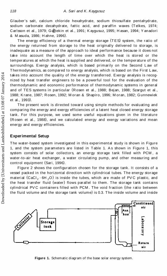
The water-based system investigated in this experimental study is shown in Figure
1, and the system parameters are listed in Table 1. As shown in Figure 1, this
system consists of solar colle ctors, an ene rgy storage tank filled with PCM, a
water-to-air he at exchanger, a wate r circulating pump, and othe r me asuring and
( )control equipment Sari, 1996 .
Figure 2 shows the configuration chosen for the storage tank. It consists of a
ve ssel packed in the horizontal dire ction with cylindrical tubes. The energy storage
( )material CaCl ? 6H O is inside the tubes, which are made of PV C plastic, and2 2
( )the heat transfer fluid wate r flows paralle l to them. The storage tank contains
(cylindrical PV C containe rs filled with PCM. The void fraction the ratio between
)the fluid volume and the storage tank volume is 0.3. The inside volume and inside
Figure 1. Schematic diagram of the base solar ene rgy system.
Dow
nloa
ded
by [
Uni
vers
itaet
s un
d L
ande
sbib
lioth
ek]
at 1
3:08
07
Janu
ary
2014
Latent Heat Energy Storage System s 119
Table 1
W ater-based system
Parameter V alue
Colle ctor
Number of glass covers 1
Thickness of glass cover 0.004 m
Refractive index 1.45
Collector plate absorptance 0.90
Collector emittance 0.85
Collector e fficiency factor 0.852( )Black and side losses 1.20 kJ r h m K
2( )Mass flow rate 40 kg r h m2
Total colle ctor are a 30 m
Number of colle ctors 18
System circuit pipe
Length 40 m
Diameter 0.04 m
( )He at loss 20 kJ r h K3( )Fluid density water 1000 kg r m
( )Fluid specific heat 4.197 kJ r kg K
Ambient temperature 18 8 CEnergy storage tank
3V olume 3.65 m2( )Thermal loss 0.210 W r m 8 C
( )Shape L r D 2.46
Initial temperature 18 8 C
surface area of the energy storage tank are given by V and A , re spective ly. Thest st
number of cylindrical PVC containe rs inside the storage tank is N . The radius ofc
the cylinder containe rs is r , and the length of the cylindrical tube containers isc
given by L . Also, the radius and length of the ene rgy storage tank are given by R st
and L , re spective ly. The r r L is 0.01, and this ratio is small enough to minimizest c
radial he at conduction in the storage mate rial.
Energy Analysis
The following equations we re used to calculate the enthalpy variation.
Charging period
( ) ( ) ( )Q s m Cp T y T q m h q m Cp T y T 1s w m 1 sl l 2 m
( ) ( )D E s H y H y Q 21 a b 1 , l
( ) ( ) ( )D E s H y H s m tCp T y T 31 a b w s 1 2
Discharging period
( ) ( ) ( )D E s H y H s m tCp T y T 42 d c w s 2 1
Dow
nloa
ded
by [
Uni
vers
itaet
s un
d L
ande
sbib
lioth
ek]
at 1
3:08
07
Janu
ary
2014
A. Sari and K. Kaygusuz120
Figure 2. Schematic configuration of the energy storage tank.
The following equation was used to calculate energy efficiency of the energy
storage system:
Energy recovered from TES during dischargingh sen ergy
Energy input to TES during charging( )5
H y H Qd c lh s s 1 yen ergy
H y H H y Ha b a b
Exergy Analysis
The following equations we re used to calculate the entropy variation.
Charging period
( ) ( ) ( )D S s S y S s m tCp ln T rT 61 a b w s 1 2
Discharging period
( ) ( ) ( )D S s S y S s m tCp ln T r T 72 d c w s 2 1
The following equations we re used to calculate the exergy variation.
Charging period
( ) ( ) ( )e y e s H y H y T S y S 8a b a b 0 a b
Dow
nloa
ded
by [
Uni
vers
itaet
s un
d L
ande
sbib
lioth
ek]
at 1
3:08
07
Janu
ary
2014
Latent Heat Energy Storage System s 121
Discharging period
( ) ( ) ( )e y e s H y H y T S y S 9d c d c 0 d c
Exergy e fficiency for the energy storage system can be calculated as
Exe rgy recovered from TES during dischargingh sexe rgy
Exe rgy input to TES during charging
e y e e q Id c Q l( )h s s 1 y 10exe rgy e y e e y ea b a b
Results an d Discu ss ion
We have analyzed the exe rgy and energy performance of the latent he at TES
system for domestic he ating in Trabzon, Turkey, both expe rimentally and theore ti-
cally. The experiments we re pe rformed under cle ar-sky winter conditions so that a
quasi ] ste ady state could be re alized. For most runs the system was started we ll
ahead of solar noon, and the quasi ] steady state of the operation was usually
achieved around solar noon during the charging period. The data we re obtained for
various ambient and operational conditions, with ambient air temperature s ranging
from y 1 to 12 8 C and total solar radiation in the plane of the colle ctor from 500 to
900 W rm 2 d.
From the viewpoint of the Second Law of Thermodynamics, the optimum
charge period for energy storage depends upon the total radiation on a sloped
collector surface. But the optimum discharge period for a storage tank is that
corre sponding to the maximum discharge e fficiency. We can say that the optimum
discharge period is more usefully dete rmined using exe rgy rather than energy
e fficiency. But in the TES system the ene rgy and exergy efficiencie s we re low due
to low the rm al conductivity of the PV C containe rs filled by PCM in the energy
storage tank. O n the othe r hand, exe rgy conside rs the quality and, for a he at
transfer fluid, is dependent on the temperature s of the PCM and ambient air
temperature.
( )Temperature variation of PCM CaCl ? 6H O with time of day in the storage2 2
tank is shown in Figure 3. The figure shows that there is a semithermal stratifica-
tion in the TES system. This situation shows that the time of me lting and
solidification of the PCM varie s from the bottom to the upper side of the store . In
othe r words, the PCM at the bottom me lts less than the PCM at the middle point,
and the PCM at the middle point melts less than the PCM at the upper point in
the storage tank. It is also evident that, around solar noon, the temperatures of the
PCM in the store are roughly at a maximum value .
Me an temperature variation of the he at transfer fluid at the exit of the storage
tank with time of day during charging and discharging pe riods is shown in Figure 4.
It is also evident that, around solar noon, the exit wate r temperature of the store is
roughly at a m aximum value .
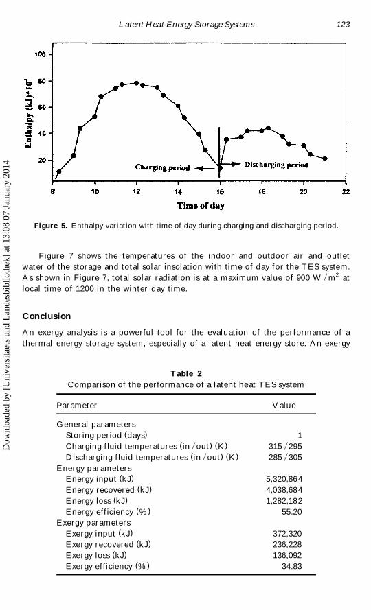
Figure 5 shows the enthalpy variation with time of day during charging and
discharging periods. It shows that the amount of enthalpy is at a maximum value
( )around solar noon. It is also evident that the amount of stored enthalpy or ene rgy
during the charging period is higher than that ene rgy recovered during the
Dow
nloa
ded
by [
Uni
vers
itaet
s un
d L
ande
sbib
lioth
ek]
at 1
3:08
07
Janu
ary
2014
A. Sari and K. Kaygusuz122
Figure 3. Temperature variation of calcium chloride hexahydrate with time of day in
storage tank. T1, upper temperature; T2, middle temperature ; T3, bottom temperature .
discharging pe riod. This re sult is in agreement with the result given in the
( )literature Rosen e t al., 1988 . This me ans that the ene rgy stored is gre ater than
( )the energy recovered Table 2 .
Figure 6 shows the exe rgy variation with time of day during charging and
discharging periods. It also shows that the amount of exergy is at a m aximum value
around solar noon. We can say from Figure 6 that the exergy stored is gre ate r than
( )the exe rgy recove red Table 2 .
Figure 4. Temperature variation with time of day during charging and discharging period.
Dow
nloa
ded
by [
Uni
vers
itaet
s un
d L
ande
sbib
lioth
ek]
at 1
3:08
07
Janu
ary
2014
Latent Heat Energy Storage System s 123
Figure 5. Enthalpy variation with time of day during charging and discharging period.
Figure 7 shows the temperatures of the indoor and outdoor air and outlet
water of the storage and total solar insolation with time of day for the TES system.
As shown in Figure 7, total solar radiation is at a maximum value of 900 W r m2 at
local time of 1200 in the winter day time.
Con clus ion
An exergy analysis is a powe rful tool for the evaluation of the perform ance of a
thermal energy storage system, especially of a latent he at ene rgy store. An exe rgy
Table 2
Comparison of the pe rformance of a latent he at TES system
Parameter V alue
General parameters
( )Storing pe riod days 1
( ) ( )Charging fluid temperatures in rout K 315 r295
( ) ( )Discharging fluid temperature s in rout K 285 r305
Energy parameters
( )Energy input kJ 5,320,864
( )Energy recove red kJ 4,038,684
( )Energy loss kJ 1,282,182
( )Energy e fficiency % 55.20
Exergy parameters
( )Exe rgy input kJ 372,320
( )Exe rgy recovered kJ 236,228
( )Exe rgy loss kJ 136,092
( )Exe rgy e fficiency % 34.83
Dow
nloa
ded
by [
Uni
vers
itaet
s un
d L
ande
sbib
lioth
ek]
at 1
3:08
07
Janu
ary
2014
A. Sari and K. Kaygusuz124
Figure 6. Exergy variation with time of day during charging and discharging period.
analysis is based on the Second Law of Thermodynamics and takes into account
the quality and use fulne ss of the energy transfe red. Meanwhile , an ene rgy analysis,
which is based on the First Law of Thermodynamics, doe s not take into account
the following factors: time required for charge and discharge processes, the
temperatures at which the heat is supplied and discharged, and the temperature of
the surroundings. The desirable characte ristics of the Second Law analysis arise s
Figure 7. Temperature and insolation variations with time of day: curve 1, insolation; 2,
outlet water temperature of storage; 3, indoor air temperature ; and 4, outdoor air tempera-
ture .
Dow
nloa
ded
by [
Uni
vers
itaet
s un
d L
ande
sbib
lioth
ek]
at 1
3:08
07
Janu
ary
2014
Latent Heat Energy Storage System s 125
from the fact that the Second Law of Thermodynamics assesse s the quality of
energy, but the First Law focuses on the quantity of energy.
In this study, we used some expressions given in the lite rature for evaluating
the ene rgy and exergy e fficiencie s during charging and discharging periods, the
amounts of energy and exe rgy changing, and the changing storage -fluid tempera-
ture for the discharge process of a closed, semithe rmal stratified, latent he at
thermal energy storage system. Calculations have shown that the difference be-
( )tween the results of energy and exe rgy analysis is significant see Table 2 . The
authors fee l that, since exergy is a me asure of the quality or usefulness of energy,
exe rgy pe rformance measures are more significant than ene rgy pe rformance mea-
sure s and that the exe rgy analysis should be considered in the calculation and
comparison of the charge and discharge time for the thermal ene rgy storage system
presented here.
Nom enclature
w ( )xC specific he at kJ r kg 8 Cp
w ( )xh latent he at of phase transition J r kg Ks l
H enthalpy
( )I exergy losse s or consumption
( )m mass of PCM kg
( )m mass flow rate of wate r kg rminw
( )Q stored energy kJs
S entropy
( )t time min
( )T temperature K
( )T phase transition temperature of salt hydrate Km
( )T inle t temperature of wate r K1
( )T outle t temperature of water K2
e exergy
h efficiency
Subscripts
a inle t flow at charging period
b outle t flow at charging pe riod
c inle t flow at discharging period
d outle t flow at discharging pe riod
f final state
i initial state
l liquid
s solid
1 charging period
2 discharging period
Referen ces
Abhat, A. 1983. Low temperature latent heat thermal ene rgy storage: Heat storage materi-
als. Solar Energy 30:313 ] 331.
Dow
nloa
ded
by [
Uni
vers
itaet
s un
d L
ande
sbib
lioth
ek]
at 1
3:08
07
Janu
ary
2014
A. Sari and K. Kaygusuz126
Bejan, A. 1988. Advanced engineering therm odyn amics. New York: John Wiley and Sons.
Carlsson, B., H. Stymne, and G. Wettermark. 1979. An incongruent he at-of-fusion
system } CaCl ? 6H O } made congruent through modification of the chemical compo-2 2
sition of the system. Solar Energy 23:343 ] 350.
Gultekin, N., T. Ayhan, and K. Kaygusuz. 1991. Heat storage chemical materials which canÈbe used for domestic heating by heat pumps. Energy Conversion Managem ent 32:311 ] 317.
Gunnewiek, L. H., S. Nguyen, and M. A. Rosen. 1993. Evaluation of the optimum discharge
period for closed thermal energy storages using ene rgy and exergy analyses. Solar
Energy 51:39 ] 43.
Hahne, E . 1996. Thermal conservation technologie s. Presented at the First Trabzon Interna-
tional Energy and Environment Symposium, July 29 ] 31, Trabzon, Turkey.
Hasan, A. 1994. Phase-change material ene rgy storage system employing palmitic acid. Solar
Energy 52:143 ] 154.
KakacË , S., E . PaykocË , and Y. Yener. 1989. Energy Storage System s. NATO ASI Series. Kluwer
Academic.
Kaygusuz, K. 1995. Experimental and theore tical investigation of latent heat storage for
water based solar he ating systems. Energy Conversion Managem ent 36:315 ] 323.
Krane , R. J. 1987. A second law analysis of the optimum design and operation of thermal
ene rgy storage systems. International Journ al of Heat and Mass Transfer 30:43 ] 57.
Moran, M. J. 1982. Availability analysis: A guide to efficien t energy use. Englewood Cliffs,
N. J.: Prentice-Hall.
Moran, M. J., and H. N. Shapiro. 1996. Fundam entals of engineering therm odynam ics. New
York: John Wiley.
Rosen, M. A. 1992. Appropriate thermodynamic performance me asures for closed systems
for thermal ene rgy storage . ASME Journal of Solar Energy Engineering 114:100 ] 105.
Rosen, M. A., F. C. Hooper, and L. N. Barbaris. 1988. Exergy analysis for the evaluation of
the performance of closed thermal ene rgy storage systems. ASME Journal of Solar
Energy Engineering 110:255 ] 261.
Sari, A. 1996. Pe rformance calculation of energy storage system using energy and exergy
analysis. M.S. thesis, Karadeniz Technical University, Trabzon, Turkey.
Szargut, J., D. R. Morris, and F. R. Steward. 1988. Exergy analyses of therm al, chem ical, and
m etallurgical processes. New York: Hemisphere Publishing.
Telkes, M. 1974. Solar energy storage. ASHRAE Journal September:34 ] 44.
Yanadori, M., and T. Masuda. 1986. He at transfe rential study on a he at storage container
with phase change material. Solar Energy 36:169 ] 177.