Energy integration and analysis of SOFC based micro-CHP and other renewable systems using biomass waste derived syngas Jhuma Sadhukhan 1* , Yingru Zhao 2 , Matthew Leach 3 , Nigel P Brandon 2 and Nilay Shah 4 1 Centre for Process Integration, School of Chemical Engineering & Analytical Science, The University of Manchester, P. O. Box 88, Manchester, UK, M60 1QD 2 Department of Earth Science and Engineering, Imperial College London, South Kensington Campus, London, UK, SW7 2AZ 3 Centre for Environmental Strategy, School of Engineering, University of Surrey, Guildford, Surrey, UK, GU2 7XH 4 Centre for Process Systems Engineering, Imperial College London, South Kensington Campus, London, UK SW7 2AZ Abstract The objective of this paper was to design energy integrated solid oxide fuel cell (SOFC) based micro- combined heat and power (micro-CHP) systems using syngas derived from lignocellulosic biomass waste. The novel contributions of this work include 1) integration of syngas between a community-scale biomass gasification plant and SOFC based micro-CHP systems in buildings; 2) heat integrated designs of SOFC based micro-CHP systems; 3) integration between SOFC and other heat-led renewable technologies, such as, syngas boilers, ground source heat pump (GSHP) and air source heat pump (ASHP). Conceptual process design frameworks including detailed heat recovery strategies were developed using Aspen plus. It is demonstrated that increases in heat integration between the SOFC inlet and outlet gases enhance the power-to-heat generation ratio from the SOFC albeit at a higher cost of heat exchanger area. A straw (14.6 MJ/kg LHV) based community-scale gasification plant can generate 50-100 kW e of electricity at an overall CHP generation efficiency of ~42%, while if integrated to SOFC based micro-CHP systems (1 kW e ) in individual dwellings via syngas, the overall energy efficiency can be greatly enhanced to ~85%. It is envisaged that the SOFC should be operated at the highest electrical efficiency based on optimal heat integration, however, this needs to be coupled to other heat-led renewable technologies in order to meet the high residential heat to power demand ratio in the UK. Around 2.2 times more syngas may be required in boilers for supplementing residential heating. In integration with a GSHP loop, the flue gas from SOFC can itself be used as a refrigerant and energy integration between the two systems can achieve an overall efficiency of ~90%. Keywords: distributed energy, syngas to micro-CHP, residential energy, fuel cell, ground source heat pump and SOFC integration, biomass waste gasification * Author/s to whom correspondence should be addressed: E-mail: [email protected]
Transcript
Energy integration and analysis of SOFC based micro-CHP and other renewable systems using
biomass waste derived syngas
Jhuma Sadhukhan1*, Yingru Zhao2, Matthew Leach3, Nigel P Brandon2 and Nilay Shah4
1Centre for Process Integration, School of Chemical Engineering & Analytical Science, The University of Manchester, P. O.
Box 88, Manchester, UK, M60 1QD
2Department of Earth Science and Engineering, Imperial College London, South Kensington Campus, London, UK, SW7 2AZ
3Centre for Environmental Strategy, School of Engineering, University of Surrey, Guildford, Surrey, UK, GU2 7XH
4Centre for Process Systems Engineering, Imperial College London, South Kensington Campus, London, UK SW7 2AZ
Abstract
The objective of this paper was to design energy integrated solid oxide fuel cell (SOFC) based micro-
combined heat and power (micro-CHP) systems using syngas derived from lignocellulosic biomass waste.
The novel contributions of this work include 1) integration of syngas between a community-scale biomass
gasification plant and SOFC based micro-CHP systems in buildings; 2) heat integrated designs of SOFC
based micro-CHP systems; 3) integration between SOFC and other heat-led renewable technologies, such
as, syngas boilers, ground source heat pump (GSHP) and air source heat pump (ASHP). Conceptual
process design frameworks including detailed heat recovery strategies were developed using Aspen plus.
It is demonstrated that increases in heat integration between the SOFC inlet and outlet gases enhance the
power-to-heat generation ratio from the SOFC albeit at a higher cost of heat exchanger area. A straw (14.6
MJ/kg LHV) based community-scale gasification plant can generate 50-100 kWe of electricity at an
overall CHP generation efficiency of ~42%, while if integrated to SOFC based micro-CHP systems (1
kWe) in individual dwellings via syngas, the overall energy efficiency can be greatly enhanced to ~85%. It
is envisaged that the SOFC should be operated at the highest electrical efficiency based on optimal heat
integration, however, this needs to be coupled to other heat-led renewable technologies in order to meet
the high residential heat to power demand ratio in the UK. Around 2.2 times more syngas may be required
in boilers for supplementing residential heating. In integration with a GSHP loop, the flue gas from SOFC
can itself be used as a refrigerant and energy integration between the two systems can achieve an overall
The concept of microgeneration implies to combined heat and power (CHP) generation with low or zero
carbon emission, by individuals, businesses and communities, at or near the point of use1-2. The UK
Government made an important commitment in the Energy Act 2004 by developing an ongoing
microgeneration strategy in order to create a sustainable residential energy market and thereby tackle its
contribution to climate change2-3. The microgeneration or self generation concept for dwellings is
associated with several advantages, such as follows:
(1) Cutting emissions of greenhouse gases
(2) Reducing the number of people living in fuel poverty
(3) Reducing the demands on transmission systems and distribution systems
(4) Reducing the need for those systems to be modified
(5) Enhancing the availability of electricity and heat for consumers
(6) Encourage consumer engagement with energy efficient technologies
The micro-CHP in this paper is referred to the generation of 1 kWe of electricity from a dwelling
installation1-4. This is differentiated from a community-scale (multi-dwelling) electricity generation in the
range of 50-100 kWe4. The community generation is referred to the supply of heat or combined heat and
power from a central source to a set of buildings in a community. It also allows customers from various
sectors such as domestic, schools, offices, as well as industrial sectors. As identified in many studies by
the Energy Saving Trust, the main potential use of micro-CHP is in conjunction with community based
generation schemes1.
Fuel cells have become a very important energy technology in the UK and worldwide, due to their
inherently clean, greener and efficient operation. The SOFC can be used to micro generate electricity and
heat simultaneously and have therefore become very relevant for dwelling micro-CHP generation. The
SOFC can utilise heat of oxidization of gaseous fuels such as hydrogen, syngas, natural gas, etc. in the
anode in the presence of an oxidant in the cathode, into electricity. The performance of a SOFC when
fuelled directly with pure hydrocarbons, such as, methanol, has also been investigated and for the
application in electric vehicles5-7. Even greater environmental benefits can be gained if gaseous fuels, such
as syngas from waste materials, which is a good source of renewable hydrogen, can be used as a fuel to
the SOFC8-9. Our previous study included performance analysis of overall integrated biomass gasification
fuel cell systems in one infrastructure, in which the exhaust gases from a SOFC were fed to an
interconnected fluidized bed biomass gasifier, in addition to the integration of the syngas from the gasifier
to the SOFC9. Such schemes exploiting high temperature heat and material integration between the
gasifiers and SOFCs can be implemented for community scale generations. More recently, the SOFC has
also been studied for application in residential micro-CHP10-14. Authors have investigated into the viability
of newly developed micro-CHP concepts, e.g. fuel cells and sterling engines, integrated with thermal
storage units, etc. in the context of UK’s residential heat and power demands, economics and energy
policies.
The UK renewable energy roadmap shows solar heat, biomass boilers, ground source heat pump (GSHP)
and air source heat pump (ASHP) as the main heat-led technologies15. Typically, 68-82% (new – existing
buildings respectively) of the residential energy is required in the form of heat, such as residential hot
water and space heating10-14. A micro-CHP system in the UK thus generally invokes heat-led renewable
technologies alongside with connection to national electricity grid in order to ensure a consistent supply of
power. The heat-led micro-CHP has less consistency in operation in summer months when there is little or
no heat demand. The SOFC can substitute heat-led micro-CHP and enable onsite power generation
renewably and effectively. The SOFC have high electrical efficiency and low heat-to-power ratio. Thus, if
applied to a single household in the UK, the thermal efficiency, hence CHP generation efficiency needs to
be enhanced significantly, without compromising on the electrical efficiency. The objective of this study
was the heat integrated design of high efficiency SOFC for UK residential micro-CHP. Heat recovery
from the exhaust gas from SOFC operating at elevated temperatures of above 500oC, can significantly
enhance the overall CHP generation efficiency. Additionally, thermal coupling between SOFCs and heat
storage systems can be considered to respond to large rapid residential heat demands13. This work further
investigates into the integration of SOFCs with other forms of heat-led renewable technologies, such as
the GSHP and ASHP systems, identified for UK micro-CHP applications15, using conceptual low
temperature heat integration approaches16-17. The SOFC, an effective power-led technology, and GSHP
that utilizes ground-based energy into useful heat generation, are complementary to each other. There
exists a good thermodynamic integration synergy between them, which must be explored using theoretical
and conceptual studies before any expensive demonstration work, in order to comprehend the basic
structure, efficiencies and directions for further research15, which is the objective of this study.
The modeling of fuel cells spans from electrochemical reaction and mass and heat transport modeling18-20
to detailed microstructural modeling21 and multi-scale modeling, e.g. CFD22, approaches. Detailed
modeling of SOFC is not within the scope of this study. For the conceptual heat integrated designs of
SOFC, an Aspen Plus23 simulation framework for the generation of kinetic parameters and mass and
energy balances9 and an Excel based irreversible steady-state model, wherein irreversibilities resulting
from electrochemical reaction, electrical resistance, and heat transfer to the environment were taken into
account18-20, were used. This paper is structured as follows. The first section has highlighted the main
features of the straw based community-scale gasification plant under consideration24. Provisions to
generate clean syngas fuel from the biomass gasification plant for SOFC based micro-CHP systems as
well as CHP using gas turbine based combined cycle were considered. Thereafter, the heat integrated high
efficiency SOFC schemes that utilise straw derived syngas have been presented. Finally, integration
between SOFC based micro-CHP schemes and supplementary firing, and GSHP and ASHP systems is
analysed in response to high energy demands by the UK residential sector. Each section contains an Aspen
Plus simulation based energy integration methodology and analysis of results for respective systems.
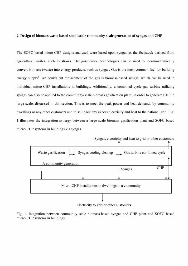
2. Design of biomass waste based small scale community-scale generation of syngas and CHP
The SOFC based micro-CHP designs analysed were based upon syngas as the feedstock derived from
agricultural wastes, such as straws. The gasification technologies can be used to thermo-chemically
convert biomass (waste) into energy products, such as syngas. Gas is the most common fuel for building
energy supply1. An equivalent replacement of the gas is biomass-based syngas, which can be used in
individual micro-CHP installations in buildings. Additionally, a combined cycle gas turbine utilizing
syngas can also be applied to the community-scale biomass gasification plant, in order to generate CHP in
large scale, discussed in this section. This is to meet the peak power and heat demands by community
dwellings or any other customers and to sell back any excess electricity and heat to the national grid. Fig.
1 illustrates the integration synergy between a large scale biomass gasification plant and SOFC based
micro-CHP systems in buildings via syngas.
Fig. 1. Integration between community-scale biomass-based syngas and CHP plant and SOFC based micro-CHP systems in buildings.
Waste gasification Syngas cooling cleanup Gas turbine combined cycle
A community generation
Syngas
CHP
Micro-CHP installations in dwellings in a community
Electricity to grid or other customers
Syngas, electricity and heat to grid or other customers
The biomass gasification plant under consideration comprises gasifiers, gas cooling and clean up
technologies, gas turbines and heat recovery steam generators (HRSG), etc. The first three unit operations
are used to produce clean syngas feedstock for SOFC and / or gas turbine combined cycle, while the latter
two operations are investigated for CHP generation. The integration strategies developed for community-
scale syngas and CHP generation plant based on agricultural wastes, straws25, in view to improve energy
efficiency, heat recovery and cleaner operations, are as follows. The performance of the biomass
gasification plant was validated against literature25-27 and the results are presented elsewhere24.
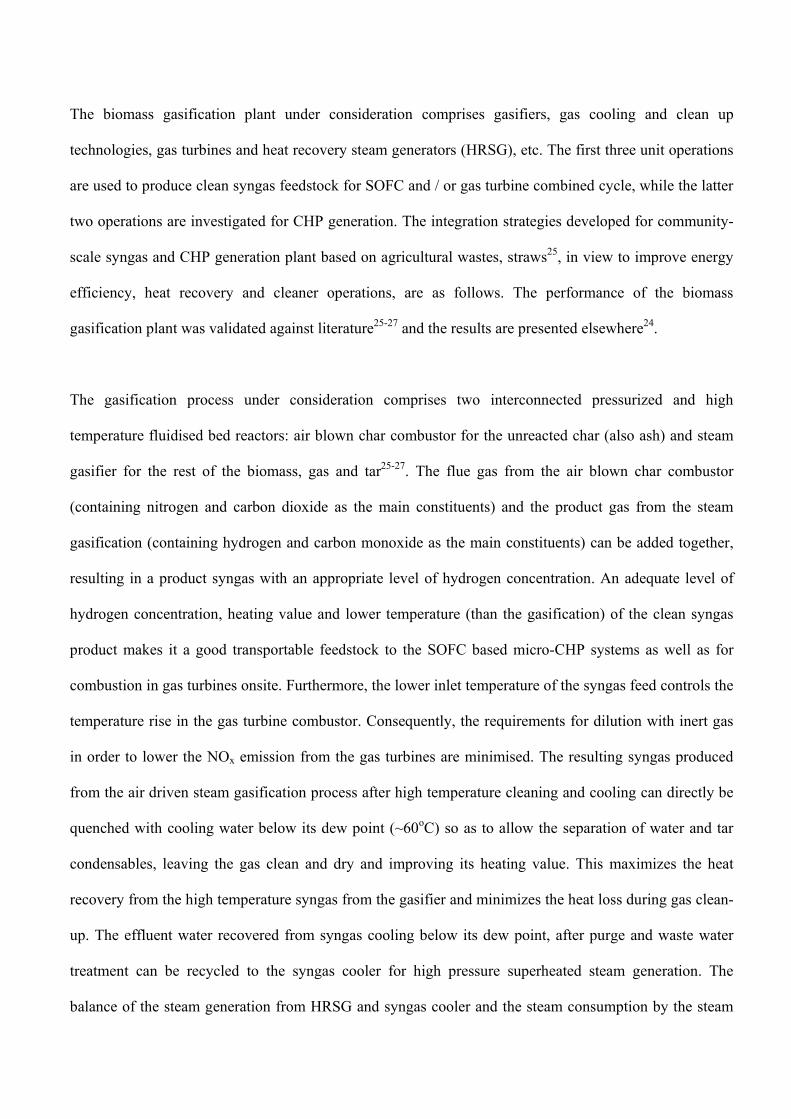
The gasification process under consideration comprises two interconnected pressurized and high
temperature fluidised bed reactors: air blown char combustor for the unreacted char (also ash) and steam
gasifier for the rest of the biomass, gas and tar25-27. The flue gas from the air blown char combustor
(containing nitrogen and carbon dioxide as the main constituents) and the product gas from the steam
gasification (containing hydrogen and carbon monoxide as the main constituents) can be added together,
resulting in a product syngas with an appropriate level of hydrogen concentration. An adequate level of
hydrogen concentration, heating value and lower temperature (than the gasification) of the clean syngas
product makes it a good transportable feedstock to the SOFC based micro-CHP systems as well as for
combustion in gas turbines onsite. Furthermore, the lower inlet temperature of the syngas feed controls the
temperature rise in the gas turbine combustor. Consequently, the requirements for dilution with inert gas
in order to lower the NOx emission from the gas turbines are minimised. The resulting syngas produced
from the air driven steam gasification process after high temperature cleaning and cooling can directly be
quenched with cooling water below its dew point (~60oC) so as to allow the separation of water and tar
condensables, leaving the gas clean and dry and improving its heating value. This maximizes the heat
recovery from the high temperature syngas from the gasifier and minimizes the heat loss during gas clean-
up. The effluent water recovered from syngas cooling below its dew point, after purge and waste water
treatment can be recycled to the syngas cooler for high pressure superheated steam generation. The
balance of the steam generation from HRSG and syngas cooler and the steam consumption by the steam
gasification unit and other cleaning processes, such as, the Rectisol process, developed by Lurgi and
Linde28, can be made available as residential heat, which can enhance the overall energetic efficiency of a
biomass gasification combined cycle plant. The Rectisol technology provides an excellent option for co-
removal of a number of contaminants to a trace level (for e.g. H2S to less than 0.1 ppm by volume), using
one integrated plant. A syngas feed to SOFC needs to be cleaned at 0.1 ppm level of purity of H2S8. The
syngas capacity reported is in the range of ~100-350 Nm3/hr28, which is in this case 337 Nm3/hr.
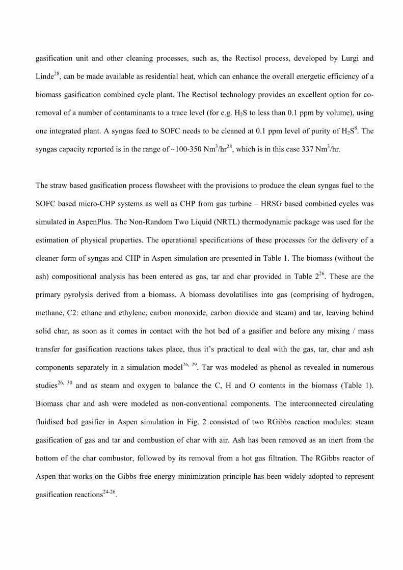
The straw based gasification process flowsheet with the provisions to produce the clean syngas fuel to the
SOFC based micro-CHP systems as well as CHP from gas turbine – HRSG based combined cycles was
simulated in AspenPlus. The Non-Random Two Liquid (NRTL) thermodynamic package was used for the
estimation of physical properties. The operational specifications of these processes for the delivery of a
cleaner form of syngas and CHP in Aspen simulation are presented in Table 1. The biomass (without the
ash) compositional analysis has been entered as gas, tar and char provided in Table 226. These are the
primary pyrolysis derived from a biomass. A biomass devolatilises into gas (comprising of hydrogen,
methane, C2: ethane and ethylene, carbon monoxide, carbon dioxide and steam) and tar, leaving behind
solid char, as soon as it comes in contact with the hot bed of a gasifier and before any mixing / mass
transfer for gasification reactions takes place, thus it’s practical to deal with the gas, tar, char and ash
components separately in a simulation model26, 29. Tar was modeled as phenol as revealed in numerous
studies26, 30 and as steam and oxygen to balance the C, H and O contents in the biomass (Table 1).
Biomass char and ash were modeled as non-conventional components. The interconnected circulating
fluidised bed gasifier in Aspen simulation in Fig. 2 consisted of two RGibbs reaction modules: steam
gasification of gas and tar and combustion of char with air. Ash has been removed as an inert from the
bottom of the char combustor, followed by its removal from a hot gas filtration. The RGibbs reactor of
Aspen that works on the Gibbs free energy minimization principle has been widely adopted to represent
gasification reactions24-26.
Table 1. Aspen modelling and operating conditions for various processes in biomass gasification based CHP flowsheet and SOFC based micro-CHP systems Process Aspen model used Specifications
Temperature oC Pressure bar Any otherconditions
Gasifier Gibbs reactor for >900 7-10steam gasifier and
char combustor
Steam to gasification <750 7-10 Steam to biomassratio: 0.6
Gas after primary pyrolysis Modeled as in Table 2 >900 7-10
Tar after primary pyrolysis Phenol: 0.46 >900 7-10(molar concentration) Steam: 0.21
Oxygen: 0.33
Char after primary pyrolysis Carbon (Table 2) >900 7-10
Air Oxygen: 0.21 20 1.013(molar concentration) Nitrogen: 0.79
Stoichiometric oxygen To char combustor:21.9 kg/hr
To GT combustor:925.8 kg/hr
Air compressors Compressor 7 (exit) Efficiency: 0.9
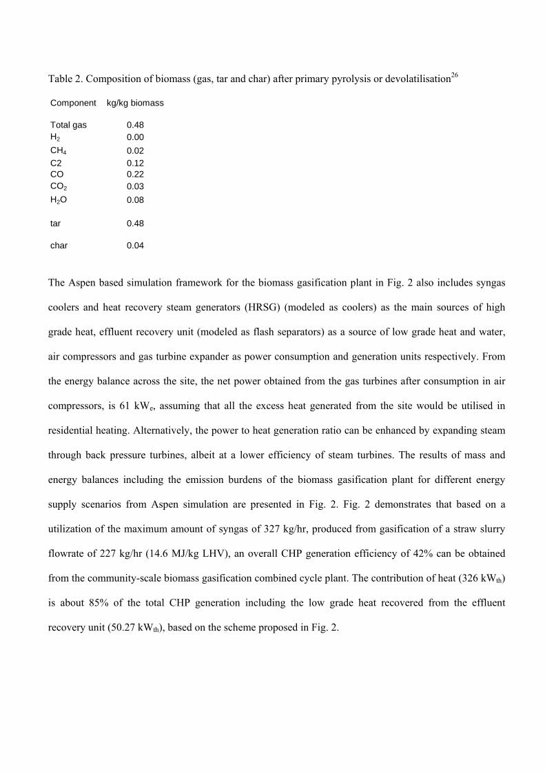
Table 2. Composition of biomass (gas, tar and char) after primary pyrolysis or devolatilisation26
Component kg/kg biomass
Total gas 0.48H2 0.00
CH4 0.02C2 0.12CO 0.22CO2 0.03
H2O 0.08
tar 0.48
char 0.04
The Aspen based simulation framework for the biomass gasification plant in Fig. 2 also includes syngas
coolers and heat recovery steam generators (HRSG) (modeled as coolers) as the main sources of high
grade heat, effluent recovery unit (modeled as flash separators) as a source of low grade heat and water,
air compressors and gas turbine expander as power consumption and generation units respectively. From
the energy balance across the site, the net power obtained from the gas turbines after consumption in air
compressors, is 61 kWe, assuming that all the excess heat generated from the site would be utilised in
residential heating. Alternatively, the power to heat generation ratio can be enhanced by expanding steam
through back pressure turbines, albeit at a lower efficiency of steam turbines. The results of mass and
energy balances including the emission burdens of the biomass gasification plant for different energy
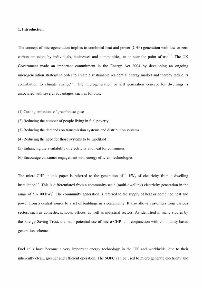
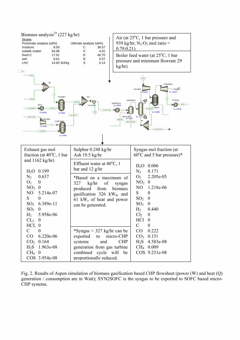
supply scenarios from Aspen simulation are presented in Fig. 2. Fig. 2 demonstrates that based on a
utilization of the maximum amount of syngas of 327 kg/hr, produced from gasification of a straw slurry
flowrate of 227 kg/hr (14.6 MJ/kg LHV), an overall CHP generation efficiency of 42% can be obtained
from the community-scale biomass gasification combined cycle plant. The contribution of heat (326 kWth)
is about 85% of the total CHP generation including the low grade heat recovered from the effluent
recovery unit (50.27 kWth), based on the scheme proposed in Fig. 2.
Biomass analysis25 (227 kg/hr) StrawsProximate analysis (wt%) Ultimate analysis (wt%)moisture 8.50 C 36.57volatile matter 64.98 H 4.91fixed C 17.91 O 40.70ash 8.61 N 0.57LHV 14.60 MJ/kg S 0.14
GASIN
TARIN
SYN2COOLASH
BIN
AIRIN
L
SYN
CYCLONE
GTEXPAND
W=-191577
COMBUST
Q=-623963
H2SREMOV
Q=-0
SUPERHTRQ=-228074
GTCOMP
W=115103
STGASIFY
Q=43266
STEAMIN2
BST2
Q=146391
STOUT2
GASPDT
CHARIN
AIRCHAR
CHAR-RCT
Q=-57987
CHARPDT
B27
EFFLUSEPQ=-50272
4
WATERREC
CHARCOMP
W=154628
WATER
B9
14
B1
SYNG2GT
SYN2SOFC
MGTHRSG
Q=-218428
GAS
POWERW
` Fig. 2. Results of Aspen simulation of biomass gasification based CHP flowsheet (power (W) and heat (Q) generation / consumption are in Watt); SYN2SOFC is the syngas to be exported to SOFC based micro-CHP systems.
Air (at 25oC, 1 bar pressure and 939 kg/hr; N2:O2 mol ratio = 0.79:0.21)
Boiler feed water (at 25oC, 1 bar pressure and minimum flowrate 29 kg/hr)
Exhaust gas mol fraction (at 40oC, 1 bar and 1162 kg/hr) H2O 0.199 N2 0.637 O2 0 NO2 0 NO 5.214e-07 S 0 SO2 6.389e-11 SO3 0 H2 5.958e-06 CL2 0 HCL 0 C 0 CO 6.220e-06 CO2 0.164 H2S 1.963e-08 CH4 0 COS 3.954e-08
Sulphur 0.248 kg/hr Ash 19.5 kg/hr
Effluent water at 40oC, 1 bar and 12 g/hr
Syngas mol fraction (at 60oC and 5 bar pressure)* H2O 0.006 N2 0.171 O2 2.205e-05 NO2 0 NO 1.218e-06 S 0 SO2 0 SO3 0 H2 0.440 Cl2 0 HCl 0 C 0 CO 0.222 CO2 0.151 H2S 4.583e-08 CH4 0.009 COS 9.231e-08
*Based on a maximum of 327 kg/hr of syngas produced from biomass gasification 326 kWth and 61 kWe of heat and power can be generated.
*Syngas < 327 kg/hr can be exported to micro-CHP systems and CHP generation from gas turbine combined cycle will be proportionally reduced.
3. Design of SOFC based micro-CHP systems
A micro-CHP system for a single dwelling is desired to produce 1 kWe of electricity1, 4 and 4-8 kWth of
heat1. Syngas as a source of renewable hydrogen from the community-scale biomass waste based
gasification plant illustrated in section 2 can be utilised in SOFC for the generation of power. A systematic
heat integration strategy was developed to preheat SOFC feed gases to a maximum extent in order to
enhance the total energy output from it, as depicted in Fig. 3 and discussed as follows. Preheating of
syngas and air to SOFC can be achieved by exchanging heat with the outlet gases from SOFC, flue gas
and nitrogen rich depleted air (with trace amount of oxygen) from anode and cathode, respectively, based
on closer specific heat values between hot and cold streams (or uniform driving force across a heat
exchanger). Preheating of feed gases facilitates endothermic reforming reactions and increases the net
exothermic heat generation (due to combustion) from the SOFC. Since the Gibbs free energy change of an
electrochemical reaction is a measure of the maximum electrical energy obtainable as work from the
reaction, preheating of feed gases to a maximum feasible temperature (allowing 20oC minimum
temperature approach between the hot and cold streams) ensures maximum energy output, hence,
maximum power generation from SOFC (Option 1 in Fig. 3). However, the maximum preheating / power
generation strategy is associated with the requirements of the maximum heat exchanger areas. Henceforth,
a co-current preheating option was also explored, which maintains a tradeoff between power to heat ratio
obtainable from the SOFC and the heat exchanger area required (Option 2).
In Option 1, after maximum preheating, the flue gas from SOFC anode still has residual low grade heat
available, which can be recovered into cooling water, heated up to 70oC (as a source of residential heat).
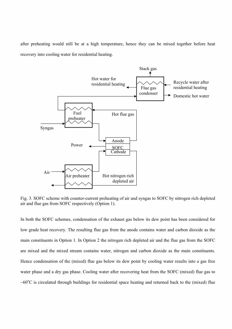
In Option 2, both the nitrogen rich depleted air from SOFC cathode and the flue gas from SOFC anode
after preheating would still be at a high temperature, hence they can be mixed together before heat
recovery into cooling water for residential heating.
Fig. 3. SOFC scheme with counter-current preheating of air and syngas to SOFC by nitrogen rich depleted air and flue gas from SOFC respectively (Option 1).
In both the SOFC schemes, condensation of the exhaust gas below its dew point has been considered for
low grade heat recovery. The resulting flue gas from the anode contains water and carbon dioxide as the
main constituents in Option 1. In Option 2 the nitrogen rich depleted air and the flue gas from the SOFC
are mixed and the mixed stream contains water, nitrogen and carbon dioxide as the main constituents.
Hence condensation of the (mixed) flue gas below its dew point by cooling water results into a gas free
water phase and a dry gas phase. Cooling water after recovering heat from the SOFC (mixed) flue gas to
~60oC is circulated through buildings for residential space heating and returned back to the (mixed) flue
Air preheater
Fuel
preheater
SOFC Cathode
Anode
Syngas
Hot nitrogen rich depleted air
Hot flue gas
Power
Air
Recycle water after residential heating
Hot water for residential heating
Domestic hot water
Flue gas condenser
Stack gas
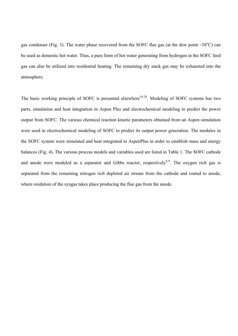
gas condenser (Fig. 3). The water phase recovered from the SOFC flue gas (at the dew point ~58oC) can
be used as domestic hot water. Thus, a pure form of hot water generating from hydrogen in the SOFC feed
gas can also be utilized into residential heating. The remaining dry stack gas may be exhausted into the
atmosphere.
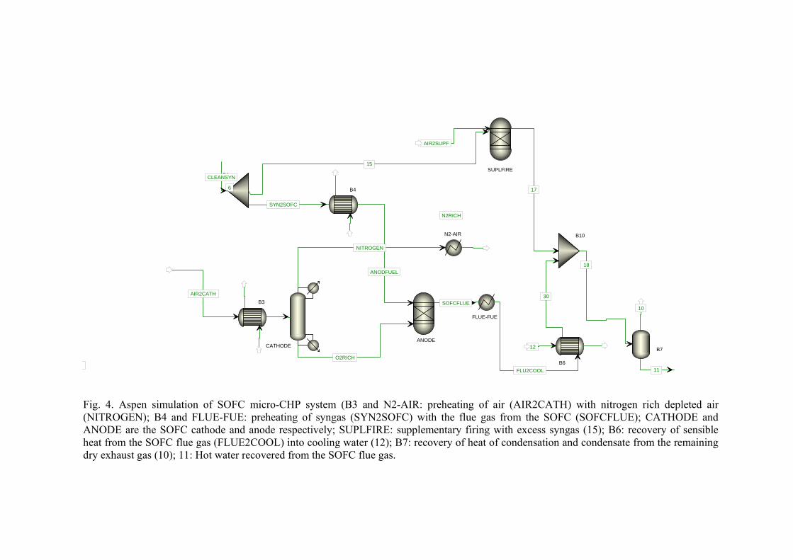
The basic working principle of SOFC is presented elsewhere18-20. Modeling of SOFC systems has two
parts, simulation and heat integration in Aspen Plus and electrochemical modeling to predict the power
output from SOFC. The various chemical reaction kinetic parameters obtained from an Aspen simulation
were used in electrochemical modeling of SOFC to predict its output power generation. The modules in
the SOFC system were simulated and heat integrated in AspenPlus in order to establish mass and energy
balances (Fig. 4). The various process models and variables used are listed in Table 1. The SOFC cathode
and anode were modeled as a separator and Gibbs reactor, respectively8-9. The oxygen rich gas is
separated from the remaining nitrogen rich depleted air stream from the cathode and routed to anode,
where oxidation of the syngas takes place producing the flue gas from the anode.
B1
15
SYN2SOFC
B4
6
ANODFUEL
NITROGEN
N2-AIR
N2RICH
SUPLFIRE
17
AIR2SUPF
B10
30
18
10
B7
11
B6
12
FLU2COOL
FLUE-FUE
SOFCFLUE
ANODE
O2RICH
CATHODE
B3
AIR2CATH
CLEANSYN
Fig. 4. Aspen simulation of SOFC micro-CHP system (B3 and N2-AIR: preheating of air (AIR2CATH) with nitrogen rich depleted air (NITROGEN); B4 and FLUE-FUE: preheating of syngas (SYN2SOFC) with the flue gas from the SOFC (SOFCFLUE); CATHODE and ANODE are the SOFC cathode and anode respectively; SUPLFIRE: supplementary firing with excess syngas (15); B6: recovery of sensible heat from the SOFC flue gas (FLUE2COOL) into cooling water (12); B7: recovery of heat of condensation and condensate from the remaining dry exhaust gas (10); 11: Hot water recovered from the SOFC flue gas.
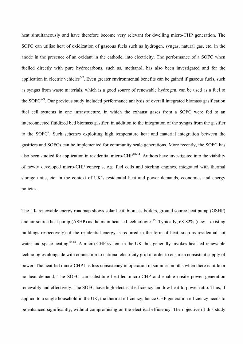
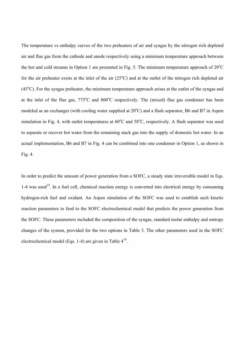
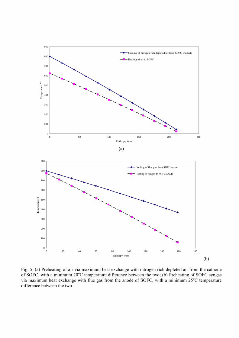
The temperature vs enthalpy curves of the two preheaters of air and syngas by the nitrogen rich depleted
air and flue gas from the cathode and anode respectively using a minimum temperature approach between
the hot and cold streams in Option 1 are presented in Fig. 5. The minimum temperature approach of 20oC
for the air preheater exists at the inlet of the air (25oC) and at the outlet of the nitrogen rich depleted air
(45oC). For the syngas preheater, the minimum temperature approach arises at the outlet of the syngas and
at the inlet of the flue gas, 775oC and 800oC respectively. The (mixed) flue gas condenser has been
modeled as an exchanger (with cooling water supplied at 20oC) and a flash separator, B6 and B7 in Aspen
simulation in Fig. 4, with outlet temperatures at 60oC and 58oC, respectively. A flash separator was used
to separate or recover hot water from the remaining stack gas into the supply of domestic hot water. In an
actual implementation, B6 and B7 in Fig. 4 can be combined into one condenser in Option 1, as shown in
Fig. 4.
In order to predict the amount of power generation from a SOFC, a steady state irreversible model in Eqs.
1-4 was used19. In a fuel cell, chemical reaction energy is converted into electrical energy by consuming
hydrogen-rich fuel and oxidant. An Aspen simulation of the SOFC was used to establish such kinetic
reaction parameters to feed to the SOFC electrochemical model that predicts the power generation from
the SOFC. These parameters included the composition of the syngas, standard molar enthalpy and entropy
changes of the system, provided for the two options in Table 3. The other parameters used in the SOFC
electrochemical model (Eqs. 1-4) are given in Table 419.
0
100
200
300
400
500
600
700
800
900
0 50 100 150 200 250
Enthalpy Watt
Tem
pera
ture
o C
Cooling of nitrogen rich depleted air from SOFC Cathode
Heating of air to SOFC
(a)
0
100
200
300
400
500
600
700
800
900
0 20 40 60 80 100 120 140 160 180
Enthalpy Watt
Tem
pera
ture
o C
Cooling of flue gas from SOFC anode
Heating of syngas to SOFC anode
(b)
Fig. 5. (a) Preheating of air via maximum heat exchange with nitrogen rich depleted air from the cathode of SOFC, with a minimum 20oC temperature difference between the two; (b) Preheating of SOFC syngas via maximum heat exchange with flue gas from the anode of SOFC, with a minimum 25oC temperature difference between the two.
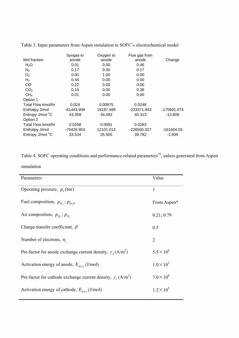
Table 3. Input parameters from Aspen simulation to SOFC’s electrochemical model
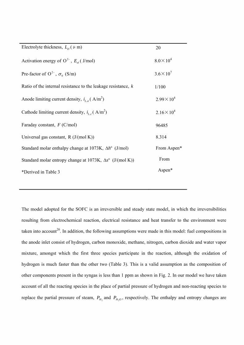
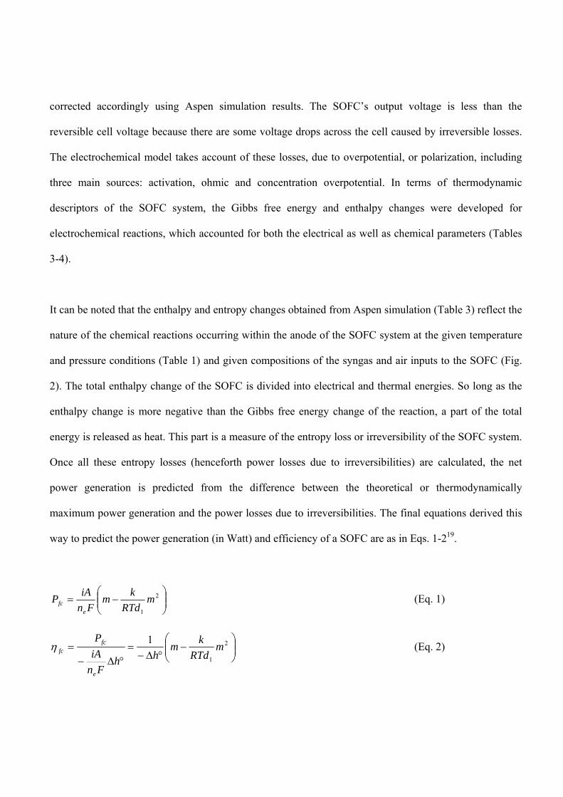
Table 4. SOFC operating conditions and performance-related parameters19, unless generated from Aspen
simulation
Parameters Value
Operating pressure, 0p (bar) 1
Fuel composition, 2Hp ; OHp
2 From Aspen*
Air composition, 2Op ;
2Np 0.21; 0.79
Charge-transfer coefficient, 0.5
Number of electrons, en 2
Pre-factor for anode exchange current density, a (A/m2) 5.5×10⁸
Activation energy of anode, ,act aE (J/mol) 1.0×10⁵
Pre-factor for cathode exchange current density, c (A/m2) 7.0×10⁸
Activation energy of cathode, ,act cE (J/mol) 1.2×10⁵
Electrolyte thickness, elL (μm) 20
Activation energy of 2O , elE ( J/mol) 8.0×10⁴
Pre-factor of 2O , 0 (S/m) 3.6×10⁷
Ratio of the internal resistance to the leakage resistance, k 1/100
Anode limiting current density, ,L ai ( A/m2) 2.99×10⁴
Cathode limiting current density, ,L ci ( A/m2) 2.16×10⁴
Faraday constant, F (C/mol) 96485
Universal gas constant, R (J/(mol K))
Standard molar enthalpy change at 1073K, h (J/mol)
Standard molar entropy change at 1073K, s (J/(mol K))
*Derived in Table 3
8.314
From Aspen*
From
Aspen*
The model adopted for the SOFC is an irreversible and steady state model, in which the irreversibilities
resulting from electrochemical reaction, electrical resistance and heat transfer to the environment were
taken into account20. In addition, the following assumptions were made in this model: fuel compositions in
the anode inlet consist of hydrogen, carbon monoxide, methane, nitrogen, carbon dioxide and water vapor
mixture, amongst which the first three species participate in the reaction, although the oxidation of
hydrogen is much faster than the other two (Table 3). This is a valid assumption as the composition of
other components present in the syngas is less than 1 ppm as shown in Fig. 2. In our model we have taken
account of all the reacting species in the place of partial pressure of hydrogen and non-reacting species to
replace the partial pressure of steam, 2HP and OHP
2, respectively. The enthalpy and entropy changes are
corrected accordingly using Aspen simulation results. The SOFC’s output voltage is less than the
reversible cell voltage because there are some voltage drops across the cell caused by irreversible losses.
The electrochemical model takes account of these losses, due to overpotential, or polarization, including
three main sources: activation, ohmic and concentration overpotential. In terms of thermodynamic
descriptors of the SOFC system, the Gibbs free energy and enthalpy changes were developed for
electrochemical reactions, which accounted for both the electrical as well as chemical parameters (Tables
3-4).
It can be noted that the enthalpy and entropy changes obtained from Aspen simulation (Table 3) reflect the
nature of the chemical reactions occurring within the anode of the SOFC system at the given temperature
and pressure conditions (Table 1) and given compositions of the syngas and air inputs to the SOFC (Fig.
2). The total enthalpy change of the SOFC is divided into electrical and thermal energies. So long as the
enthalpy change is more negative than the Gibbs free energy change of the reaction, a part of the total
energy is released as heat. This part is a measure of the entropy loss or irreversibility of the SOFC system.
Once all these entropy losses (henceforth power losses due to irreversibilities) are calculated, the net
power generation is predicted from the difference between the theoretical or thermodynamically
maximum power generation and the power losses due to irreversibilities. The final equations derived this
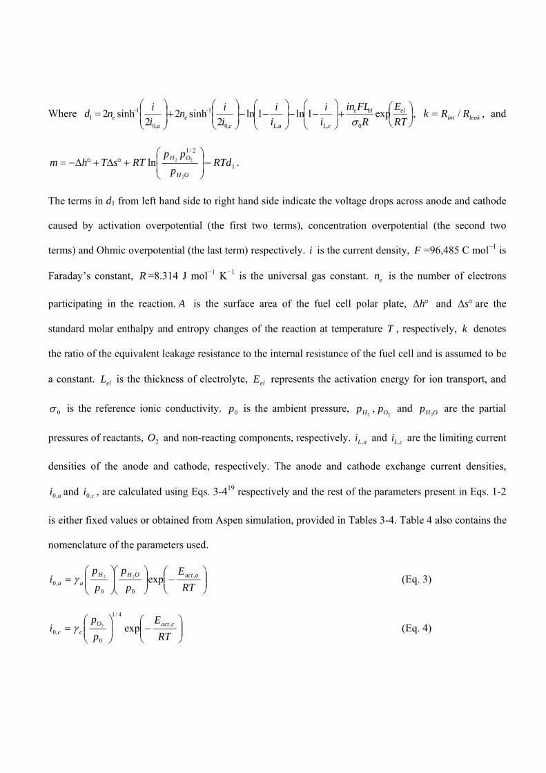
way to predict the power generation (in Watt) and efficiency of a SOFC are as in Eqs. 1-219.
2
1
mRTd
km
Fn
iAP
efc (Eq. 1)
2
1
1m
RTd
km
hhFn
iA
P
e
fcfc (Eq. 2)
Where
RT
E
R
FLin
i
i
i
i
i
in
i
ind elele
cLaLce
ae exp1ln1ln
2sinh2
2sinh2
0,,,0
1
,0
11
, leakint RRk / , and
1
2/1
2
22ln RTdp
ppRTsThm
OH
OH
.
The terms in d1 from left hand side to right hand side indicate the voltage drops across anode and cathode
caused by activation overpotential (the first two terms), concentration overpotential (the second two
terms) and Ohmic overpotential (the last term) respectively. i is the current density, F =96,485 C mol−1 is
Faraday’s constant, R =8.314 J mol−1 K−1 is the universal gas constant. en is the number of electrons
participating in the reaction. A is the surface area of the fuel cell polar plate, h and s are the
standard molar enthalpy and entropy changes of the reaction at temperature T , respectively, k denotes
the ratio of the equivalent leakage resistance to the internal resistance of the fuel cell and is assumed to be
a constant. elL is the thickness of electrolyte, elE represents the activation energy for ion transport, and
0 is the reference ionic conductivity. 0p is the ambient pressure, 2Hp ,
2Op and OHp2
are the partial
pressures of reactants, 2O and non-reacting components, respectively. ,L ai and ,L ci are the limiting current
densities of the anode and cathode, respectively. The anode and cathode exchange current densities,
ai ,0 and ci ,0 , are calculated using Eqs. 3-419 respectively and the rest of the parameters present in Eqs. 1-2
is either fixed values or obtained from Aspen simulation, provided in Tables 3-4. Table 4 also contains the
nomenclature of the parameters used.
RT
E
p
p
p
pi aactOHH
aa,
00,0 exp22 (Eq. 3)
RT
E
p
pi cactO
cc,
4/1
0,0 exp2 (Eq. 4)
a and c are pre-exponential coefficients for the anode and cathode, respectively. aactE , and cactE , are
activation energies for the anode and cathode, respectively.
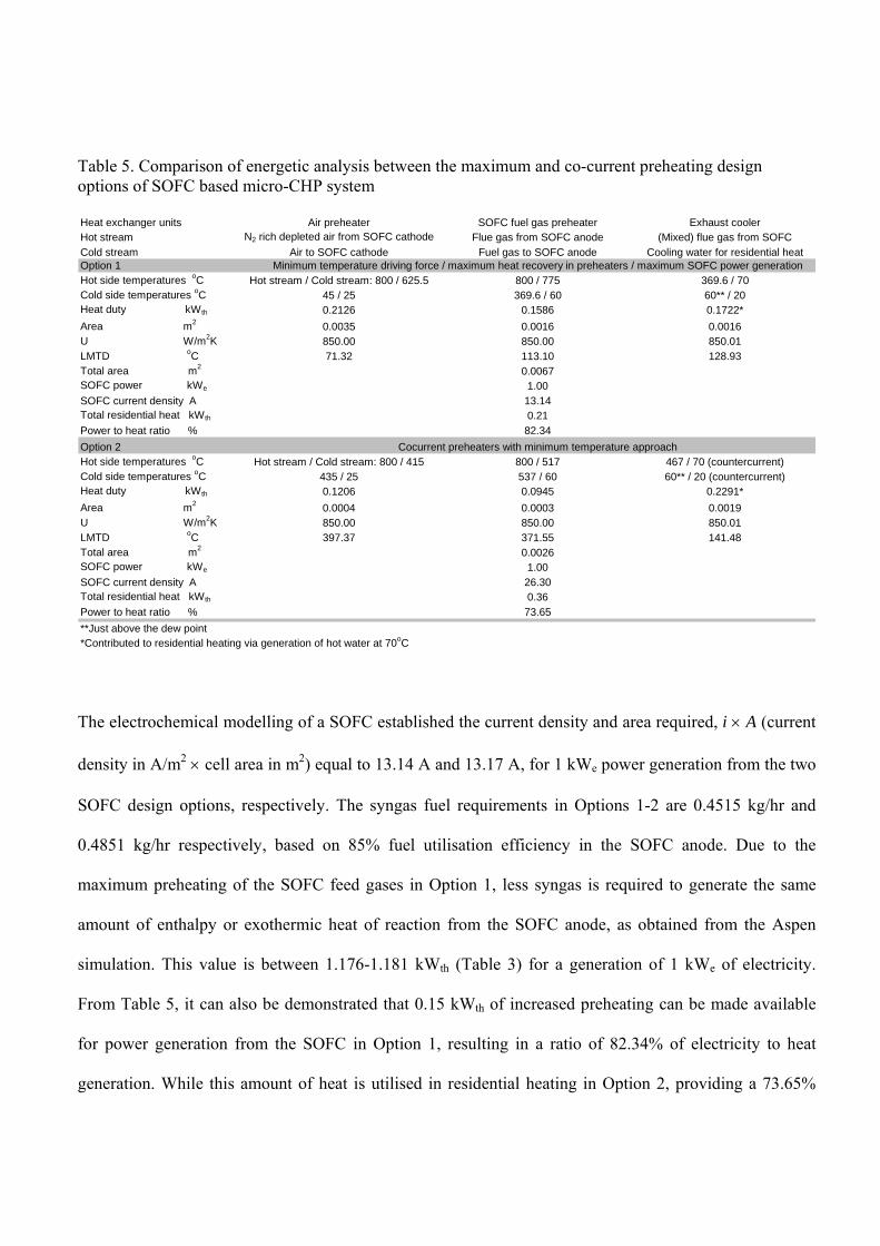
A comparison of energetic analysis between the two SOFC design options obtained from combined Aspen
simulation and electrochemical modelling, is presented in Table 5. The heat transfer related results, such
as heat duties of exchangers, outlet temperatures of either of the hot or cold streams, log mean temperature
differences (LMTD), overall heat transfer coefficients (U) and heat exchanger areas, as provided in Table
5 were established using Aspen simulations. The total residential heat supply consists of the total sensible
plus condensation heat recovered from the (mixed) flue gas from the SOFC (Fig. 3 or (mixed) flue gas
cooler and phase separator, B6 and B7 respectively in Aspen simulation in Fig. 4) as well as the
condensate recovered as domestic hot water from the remaining stack gas. The sensible heat and the heat
of condensation of the (mixed) flue gas from the SOFC recovered into cooling water circulated as a source
of residential heat are 0.172 kWth and 0.035 kWth in Option 1 and 0.229 kWth and 0.122 kWth in Option 2,
respectively. The balance of the total residential heat generation reported in Table 5 indicates the heat
recovered via condensate from the remaining dry stack gas. The heat exchanger details for the sensible
heat recovery from the flue gas to 60oC were only reported in Table 5 for a comparison purpose between
the two options.
Table 5. Comparison of energetic analysis between the maximum and co-current preheating design options of SOFC based micro-CHP system Heat exchanger units Air preheater SOFC fuel gas preheater Exhaust coolerHot stream N2 rich depleted air from SOFC cathode Flue gas from SOFC anode (Mixed) flue gas from SOFC
Cold stream Air to SOFC cathode Fuel gas to SOFC anode Cooling water for residential heatOption 1 Minimum temperature driving force / maximum heat recovery in preheaters / maximum SOFC power generationHot side temperatures oC Hot stream / Cold stream: 800 / 625.5 800 / 775 369.6 / 70Cold side temperatures oC 45 / 25 369.6 / 60 60** / 20Heat duty kWth 0.2126 0.1586 0.1722*
Area m2 0.0035 0.0016 0.0016U W/m2K 850.00 850.00 850.01LMTD oC 71.32 113.10 128.93Total area m2 0.0067SOFC power kWe 1.00SOFC current density A 13.14Total residential heat kWth 0.21
Power to heat ratio % 82.34
Option 2 Cocurrent preheaters with minimum temperature approachHot side temperatures oC Hot stream / Cold stream: 800 / 415 800 / 517 467 / 70 (countercurrent)Cold side temperatures oC 435 / 25 537 / 60 60** / 20 (countercurrent)Heat duty kWth 0.1206 0.0945 0.2291*
Area m2 0.0004 0.0003 0.0019U W/m2K 850.00 850.00 850.01LMTD oC 397.37 371.55 141.48Total area m2 0.0026SOFC power kWe 1.00SOFC current density A 26.30Total residential heat kWth 0.36
Power to heat ratio % 73.65
**Just above the dew point*Contributed to residential heating via generation of hot water at 70oC
The electrochemical modelling of a SOFC established the current density and area required, i A (current
density in A/m2 cell area in m2) equal to 13.14 A and 13.17 A, for 1 kWe power generation from the two
SOFC design options, respectively. The syngas fuel requirements in Options 1-2 are 0.4515 kg/hr and
0.4851 kg/hr respectively, based on 85% fuel utilisation efficiency in the SOFC anode. Due to the
maximum preheating of the SOFC feed gases in Option 1, less syngas is required to generate the same
amount of enthalpy or exothermic heat of reaction from the SOFC anode, as obtained from the Aspen
simulation. This value is between 1.176-1.181 kWth (Table 3) for a generation of 1 kWe of electricity.
From Table 5, it can also be demonstrated that 0.15 kWth of increased preheating can be made available
for power generation from the SOFC in Option 1, resulting in a ratio of 82.34% of electricity to heat
generation. While this amount of heat is utilised in residential heating in Option 2, providing a 73.65%
share of electricity out of the total energy generation from the SOFC. This higher electrical to heat
generation efficiency from Option 1 is obtained at the cost of 0.0273 m2/kW of more exchanger area and
lower residential heating rate. The total energy generation from Options 1-2 is 1.21 kW and 1.36 kW
respectively (Table 5).
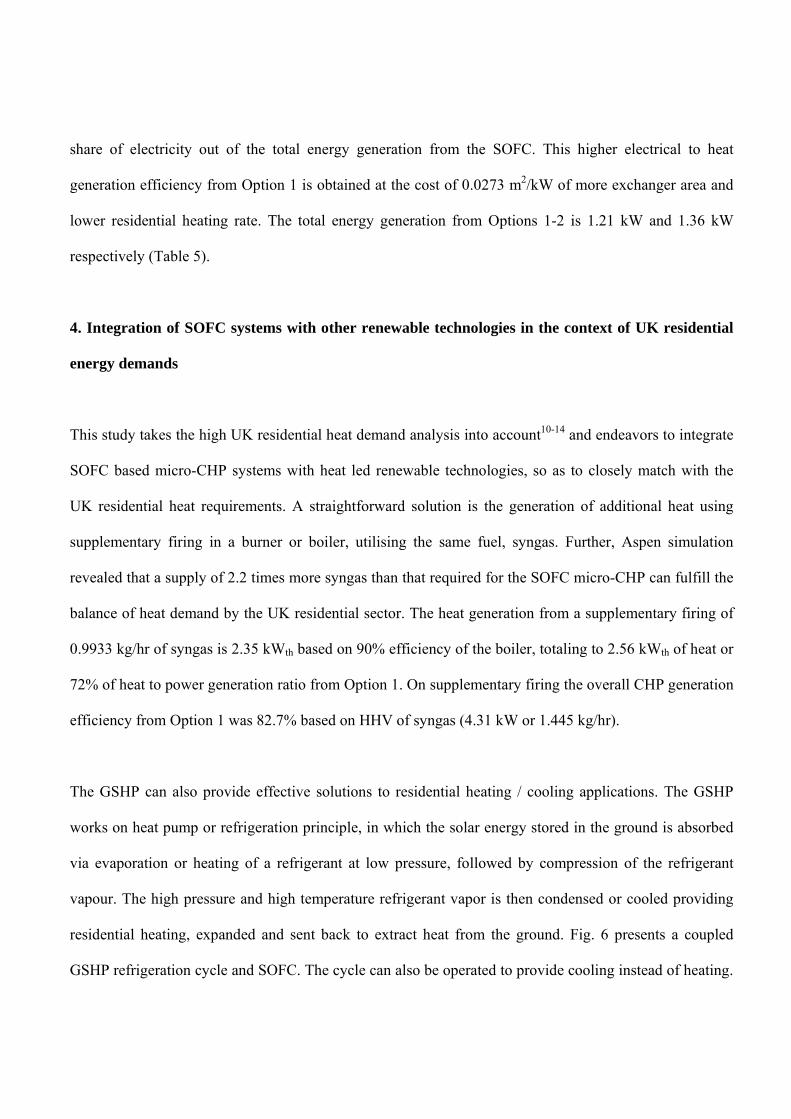
4. Integration of SOFC systems with other renewable technologies in the context of UK residential
energy demands
This study takes the high UK residential heat demand analysis into account10-14 and endeavors to integrate
SOFC based micro-CHP systems with heat led renewable technologies, so as to closely match with the
UK residential heat requirements. A straightforward solution is the generation of additional heat using
supplementary firing in a burner or boiler, utilising the same fuel, syngas. Further, Aspen simulation
revealed that a supply of 2.2 times more syngas than that required for the SOFC micro-CHP can fulfill the
balance of heat demand by the UK residential sector. The heat generation from a supplementary firing of
0.9933 kg/hr of syngas is 2.35 kWth based on 90% efficiency of the boiler, totaling to 2.56 kWth of heat or
72% of heat to power generation ratio from Option 1. On supplementary firing the overall CHP generation
efficiency from Option 1 was 82.7% based on HHV of syngas (4.31 kW or 1.445 kg/hr).
The GSHP can also provide effective solutions to residential heating / cooling applications. The GSHP
works on heat pump or refrigeration principle, in which the solar energy stored in the ground is absorbed
via evaporation or heating of a refrigerant at low pressure, followed by compression of the refrigerant
vapour. The high pressure and high temperature refrigerant vapor is then condensed or cooled providing
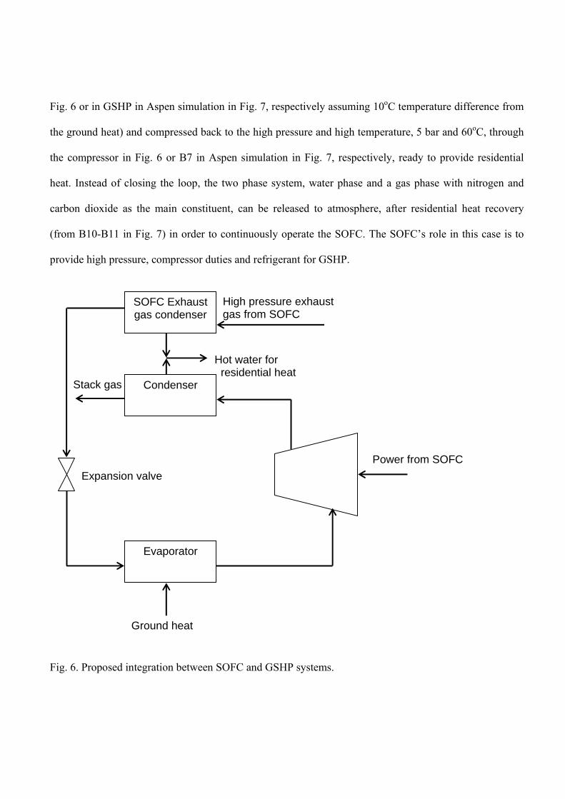
residential heating, expanded and sent back to extract heat from the ground. Fig. 6 presents a coupled
GSHP refrigeration cycle and SOFC. The cycle can also be operated to provide cooling instead of heating.
The technology exploits the fact that the temperature of the earth at moderate depth is slightly higher in
winter than the air temperature at the surface (and in summer slightly lower)15. In the UK, ground
temperatures stay fairly constant, between 10º-14ºC, throughout the year15. A SOFC and GSHP have
thermodynamic integration synergy between them. However, no demonstration result has been published
yet15. The high pressure and high temperature condensation / cooling part of a GSHP cycle can be
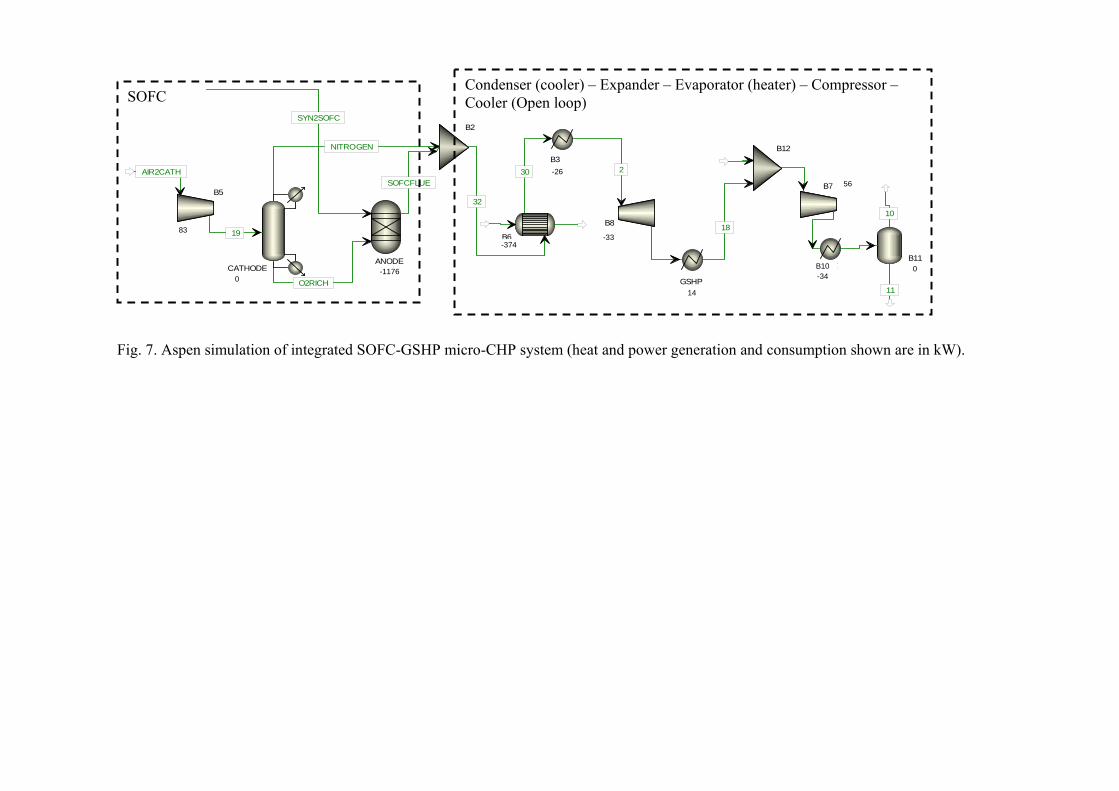
replaced by a pressurised SOFC, as illustrated in Fig. 7.
Studies have demonstrated the application of conceptual heat integration and analysis tools for providing
condensation heat for gas separation systems from refrigeration systems16. Novel designs and operability
for ethylene plant were also deduced using conceptual programming17 and more recently multi-objective
optimization30. Such studies can become highly important and relevant for more detailed integrated
renewable energy system designs, considered in the report of Energy Saving Trust15. For establishing the
thermodynamic efficiency of the integrated SOFC-GSHP system, a conceptual process configuration
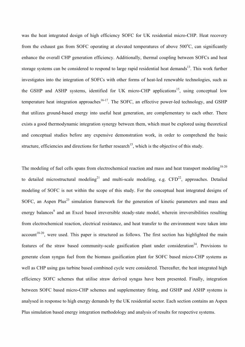
coupling a pressurised SOFC within a GSHP, depicted in Figs. 6-7, has been generated using heat
integration in Aspen Plus. The integration concept lies in the utilization of the high pressure and high
temperature exhaust gas from a SOFC as a refrigerant in a GSHP loop. A water/anti-freeze mixture can be
used as the refrigerant in a GSHP. The (mixed) flue gas from a SOFC using syngas as fuel comprised of
nitrogen (63% by mole) and carbon dioxide (16% by mole) as the main constituents with the balance
being water and thus inherently exhibits properties of refrigerant. An essential difference between this
option and the two options explored for standalone application of SOFC micro-CHP is that the heat from
the SOFC exhaust gas is extracted at high pressure (5 bar), leading to condensation of the gas, in ‘SOFC
exhaust gas condenser’ in Fig. 6 or in exchanger B6 and cooler B3 in Aspen simulation in Fig. 7,
respectively. The two phase stream is then expanded through the expansion valve in Fig. 6 or B8 in Fig. 7,
respectively, to atmospheric pressure, sent to below the ground surface to extract heat (in the evaporator in
Fig. 6 or in GSHP in Aspen simulation in Fig. 7, respectively assuming 10oC temperature difference from
the ground heat) and compressed back to the high pressure and high temperature, 5 bar and 60oC, through
the compressor in Fig. 6 or B7 in Aspen simulation in Fig. 7, respectively, ready to provide residential
heat. Instead of closing the loop, the two phase system, water phase and a gas phase with nitrogen and
carbon dioxide as the main constituent, can be released to atmosphere, after residential heat recovery
(from B10-B11 in Fig. 7) in order to continuously operate the SOFC. The SOFC’s role in this case is to
provide high pressure, compressor duties and refrigerant for GSHP.
Fig. 6. Proposed integration between SOFC and GSHP systems.
SOFC Exhaust gas condenser
High pressure exhaust gas from SOFC
Hot water for residential heat
Condenser
Evaporator
Power from SOFC
Stack gas
Expansion valve
Ground heat
SYN2SOFC
AIR2CATH
B5
W=298
O2RICH
ANODEQ=-3585
SOFCFLUE
NITROGEN
CATHODEQ=-0
19
30
32
B2
B6Q=1340
2
6
B8
W=-119
B3Q=-94
GSHPQ=14
B7 W=201
7B10Q=-122
B11Q=-0
10
11
B12
15
16
17
1883
0-1176
-374
-26
-33
14
56
B10-34
0
Fig. 7. Aspen simulation of integrated SOFC-GSHP micro-CHP system (heat and power generation and consumption shown are in kW).