135
AFTER SALES SERVICE - REGULATION MANUAL WRL • WATER / WATER CHILLER • WATER COOLED REVERSIBLE CHILLER • WATER/WATER HEAT PUMP EN EDITION: FEBRUARY 2012

AFTER SALES SERVICE - REGULATION MANUAL
WRL• WATER / WATER CHILLER• WATER COOLED REVERSIBLE CHILLER• WATER/WATER HEAT PUMP
EN
EDITION: FEBRUARY 2012

Servizio Assistenza Tecnica File WRL ENG Regulation Carel µPC 2.2.1 and Moducontrol
4.3.doc Pag. 2/135
Edizione 1 Data 17/02/2012 Autore SAT
Pag. 2/135 Pag. 2/135

Servizio Assistenza Tecnica File WRL ENG Regulation Carel µPC 2.2.1 and Moducontrol
4.3.doc Pag. 3/135
Edizione 1 Data 17/02/2012 Autore SAT
Pag. 3/135 Pag. 3/135
Indice
CONTROL WITH THE ELECTRONIC CAREL µPC BOARD 1 Index of Revisions ............................................................................................................................................................................................ 8
2 Introduction ..................................................................................................................................................................................................... 9
3 Input/Output List .......................................................................................................................................................................................... 10 3.1 Carel µPC electronic board ........................................................................................................................................................................ 10 3.2 Carel pCOe expansion board ...................................................................................................................................................................... 11 3.3 Carel pCO Compact board for Solar Panel ................................................................................................................................................. 12 3.4 Electrical schematic for Carel pCOe expansion board (accessory) ............................................................................................................ 13 3.5 Carel µPC board hardware characteristics .................................................................................................................................................. 15
3.5.1 Carel µPC board power supply (terminal J1) ................................................................................................................................. 15 3.5.2 Sensors (various analogue input terminals) ..................................................................................................................................... 15 3.5.3 Electronic expansion valve EEV connection (connector J11) ......................................................................................................... 15 3.5.1 Carel pGD1 display panel ............................................................................................................................................................... 16
4 Unit configuration code ................................................................................................................................................................................. 17 4.1 Accessories ................................................................................................................................................................................................. 17 4.2 DHW typology, see Menu Wizard paragraph password 0303 screen K6 ................................................................................................... 18
5 ModBus Network ........................................................................................................................................................................................... 19 5.1 Table of devices controlled on the ModBus network ................................................................................................................................. 19 5.2 Complete ModBus electrical connection .................................................................................................................................................... 19
6 Examples of hydraulic systems possible with the WRL unit ..................................................................................................................... 20 6.1 Cool only with freecooling (example WRL160X°°BP°S°) ........................................................................................................................ 20 6.2 Cool only with desuperheater (example WRL160X°°DBPQS°) ................................................................................................................ 20 6.3 Heat/cool with refrigerant circuit reversing (example WRL160XH°°BP°S°) ............................................................................................ 21 6.4 Heat/cool with refrigerant circuit reversing + total heat recovery (example WRL160XH°TBPQS°) ........................................................ 21 6.5 Heat/cool refrigerant circuit reversing, DHW + 3 way valve (example WRL160XH°°BP°S°) ................................................................. 22 6.6 Heat/cool refrigerant circuit reversing, DHW with pump (example WRL160XH°°BP°S°)....................................................................... 22 6.7 Heat/cool water-side reversing (example WRL160X°°°BP°S°) ................................................................................................................. 23 6.8 Drycooler with heat exchanger ................................................................................................................................................................... 23 6.9 Drycooler system side ................................................................................................................................................................................ 23 6.10 Drycooler with valve ............................................................................................................................................................................. 24 6.11 Hydraulic schematic with Solar Kit and Freecooling ............................................................................................................................ 24 6.12 Control of radiant zones ........................................................................................................................................................................ 25
7 Navigation of the Menus and sub-menus of the controller ......................................................................................................................... 26
8 User interface ................................................................................................................................................................................................. 28 8.1 pGD1 graphical terminal user guide ........................................................................................................................................................... 28
8.1.1 Back-lit Display ............................................................................................................................................................................... 28 8.1.2 On/Off and change of season of the unit from the pGD1 panel (on board unit) .............................................................................. 28
8.2 Structure of principal screen ....................................................................................................................................................................... 30
9 Menu Wizard (password 0303) ..................................................................................................................................................................... 31
10 Menu Set Up Procedure (password 0009) ................................................................................................................................................... 35
11 Menu User (push Prg key directly) ....................................................................................................................................................... 38 11.1.1 Selection of the Menu to view .......................................................................................................................................................... 38
11.2 IN/OUT menu ............................................................................................................................................................................ 39
11.3 On/Off menu .............................................................................................................................................................................. 40 11.3.1 Calendar .......................................................................................................................................................................................... 40 11.3.2 Solar management (at the moment only after special unit request at the time of order of the unit) ................................................ 41
11.4 Zone menu ................................................................................................................................................................................. 41
11.5 Menu Chiller .............................................................................................................................................................................. 43
11.6 Menu DHW ............................................................................................................................................................................... 43
11.7 Menu Clock ............................................................................................................................................................................... 45
11.8 Time zones menu ....................................................................................................................................................................... 46
12 Menu Service (password 0101).......................................................................................................................................................... 47

Servizio Assistenza Tecnica File WRL ENG Regulation Carel µPC 2.2.1 and Moducontrol
4.3.doc Pag. 4/135
Edizione 1 Data 17/02/2012 Autore SAT
Pag. 4/135 Pag. 4/135
12.1 Language ................................................................................................................................................................................... 48
12.2 Info ............................................................................................................................................................................................ 49
12.3 Zone ........................................................................................................................................................................................... 49
12.4 Chiller ........................................................................................................................................................................................ 52
12.5 Sanitary ..................................................................................................................................................................................... 53
12.6 Pumps ........................................................................................................................................................................................ 54
12.7 Solar .......................................................................................................................................................................................... 56
12.8 Hour counter .............................................................................................................................................................................. 57
12.9 Manual ....................................................................................................................................................................................... 57
12.10 Optional ..................................................................................................................................................................................... 58
12.11 Plant Conf. ................................................................................................................................................................................. 60
12.12 User ........................................................................................................................................................................................... 62
12.13 In/Out ........................................................................................................................................................................................ 63
13 Manufactory Menu (password 0202) ........................................................................................................................................................... 67
13.1 Conf.Alarm ................................................................................................................................................................................ 68
13.2 Zone ........................................................................................................................................................................................... 71
13.3 Chiller ........................................................................................................................................................................................ 71
13.4 Sanitary ..................................................................................................................................................................................... 71
13.5 Conf. Sensor .............................................................................................................................................................................. 72
13.6 Compressors .............................................................................................................................................................................. 74
13.7 Driver EEV ................................................................................................................................................................................ 74
13.8 Options ...................................................................................................................................................................................... 77
13.9 Default ....................................................................................................................................................................................... 78
14 Room sensor accessory STA/STH (Carel Th_Tune) ................................................................................................................................... 79
15 pCOe Expansion board ................................................................................................................................................................................. 80
16 Regulation ...................................................................................................................................................................................................... 81 16.1 Chiller/Heat pump ................................................................................................................................................................................. 81
16.1.1 Control of the system side water ...................................................................................................................................................... 81 16.1.2 Reversing control of the refrigerant circuit / water-side ................................................................................................................. 81 16.1.3 Control of the system pump .............................................................................................................................................................. 82 16.1.4 Control of geothermal pump ............................................................................................................................................................ 82 16.1.5 Control of the alarms relating to the refrigerant circuit .................................................................................................................. 83 16.1.6 Control of alarms relating to the hydraulic installation (system, geothermal, DHW) ..................................................................... 83 16.1.7 Control of compressor(s) operation ................................................................................................................................................. 84 16.1.8 Control to prevent refrigerant circuit high pressure........................................................................................................................ 85 16.1.9 Chiller setpoint ................................................................................................................................................................................ 85 16.1.10 Control of Chiller temperature profile ....................................................................................................................................... 85 16.1.11 Control of system supplementary heating with electric heater or boiler .................................................................................... 86
16.2 Control of DHW .................................................................................................................................................................................... 86 16.2.1 Control of the desuperheater in cooling only mode ......................................................................................................................... 87 16.2.2 Control of the total heat recovery .................................................................................................................................................... 87 16.2.3 Control of the DHW (priority) with 3 way device valve ................................................................................................................... 88 16.2.4 Control of the DHW (priority) with DHW pump .............................................................................................................................. 88 16.2.5 Control of the DHW pump of inverter type or modulating valve ..................................................................................................... 89 16.2.6 Control of the DHW pump ON/OFF ................................................................................................................................................ 89 16.2.7 Control of the condenser pump during heat recovery ...................................................................................................................... 89 16.2.8 Control of the anti-legionella treatment .......................................................................................................................................... 90

Servizio Assistenza Tecnica File WRL ENG Regulation Carel µPC 2.2.1 and Moducontrol
4.3.doc Pag. 5/135
Edizione 1 Data 17/02/2012 Autore SAT
Pag. 5/135 Pag. 5/135
16.2.9 Control of the DHW time-clock ....................................................................................................................................................... 90 16.2.10 DHW Alarms .............................................................................................................................................................................. 90 16.2.11 Control of DHW supplementary heating with immersion heater or boiler ................................................................................. 90
16.3 Control of zones .................................................................................................................................................................................... 91 16.3.1 Control of room setpoint .................................................................................................................................................................. 91 16.3.2 Control of zone setpoint ................................................................................................................................................................... 92 16.3.3 Control of dewpoint setpoint ............................................................................................................................................................ 92 16.3.4 Control of the room time-clock ........................................................................................................................................................ 93 16.3.5 Control of compressors off with zones off ........................................................................................................................................ 93 16.3.6 Control of the dehumidification ....................................................................................................................................................... 93 16.3.7 Control of zone safeties .................................................................................................................................................................... 93
16.4 Control solar heating KIT ..................................................................................................................................................................... 94 16.5 Control of freecooling KIT ................................................................................................................................................................... 95 16.6 Control of the electronic expansion valve EEV .................................................................................................................................... 96
16.6.1 Control of unit mounted EEV ........................................................................................................................................................... 96 16.6.2 Control of external EEV .................................................................................................................................................................. 97 16.6.3 EEV PID parameters ....................................................................................................................................................................... 97 16.6.4 EEV alarms ...................................................................................................................................................................................... 97
16.7 Unit On/Off ........................................................................................................................................................................................... 97 16.8 Change of season .................................................................................................................................................................................. 98 16.9 Control of low load and force off .......................................................................................................................................................... 98 16.10 Output control alarm ............................................................................................................................................................................. 98 16.11 Auxiliary Sensor B5 .............................................................................................................................................................................. 99 16.12 Control of the drycooler system ............................................................................................................................................................ 99
17 System alarms .............................................................................................................................................................................................. 100 17.1 Alarm history ...................................................................................................................................................................................... 100 17.2 Alarm list ............................................................................................................................................................................................ 100
18 BMS System ................................................................................................................................................................................................. 102 18.1 Addresses dedicated to the control of the VMF E5 ............................................................................................................................. 102 18.2 Addresses for supervision ................................................................................................................................................................... 102
19 Spare part codes for various components .................................................................................................................................................. 106
20 Setting up software version SW 2.2 ............................................................................................................................................................ 107 20.1 Programming Carel µPC board with the Carel Smart-key .................................................................................................................. 107 20.2 Addressing the EVD driver (electronic expansion valve) in pLAN network ...................................................................................... 108 20.3 Checking the configuration code of the unit ....................................................................................................................................... 108 20.4 Appendix A. Description of the unit configuration code ................................................................................................................... 109 20.5 Appendix B. Principal screen ............................................................................................................................................................. 110 20.6 Appendix C. Input output states ......................................................................................................................................................... 111 20.7 Appendix D. Menu Service, sub-menu Conf.System ......................................................................................................................... 112 20.8 Appendix E. Menu Factory. Parameters EVD ................................................................................................................................... 113 20.9 Appendix F. Addressing procedure of the Carel µPC board and the pGD1display ............................................................................ 115
20.9.1 Addressing the pGD1 terminal ...................................................................................................................................................... 115 20.9.2 Addressing the Carel µPC board ................................................................................................................................................... 115
CONTROL WITH THE ELECTRONIC MODUCONTROL BOARD
21 Index and revisions ...................................................................................................................................................................................... 118
22 Introduction ................................................................................................................................................................................................. 118
23 Hardware architecture ................................................................................................................................................................................ 119
24 User interface ............................................................................................................................................................................................... 123
25 Menu readings ............................................................................................................................................................................................. 125
26 Menu set user (password 000) .................................................................................................................................................................... 126
27 Menu customer (password 030) .................................................................................................................................................................. 129
28 Menu configuration compressor and pump (password 072) .................................................................................................................... 129
29 Menu service (password 083) ...................................................................................................................................................................... 130
30 Configuration micro-switches (dip-switch) ............................................................................................................................................... 132
31 Setting up software version SW 4.3.0 ......................................................................................................................................................... 133 31.1 Configuration parameters of the Software .......................................................................................................................................... 133 31.2 Dip-switch configuration of the board ................................................................................................................................................ 133

Servizio Assistenza Tecnica File WRL ENG Regulation Carel µPC 2.2.1 and Moducontrol
4.3.doc Pag. 6/135
Edizione 1 Data 17/02/2012 Autore SAT
Pag. 6/135 Pag. 6/135
Information present in the text In this manual the following icons will appear to clarify particular topics or as a warning:
Highlight: provides clarification on the topic that the user should be aware of.
Suggestion: provides a suggestion that can help the user to better understand and use the information of the topic being covered.
Attention! : provides information for which a lack of knowledge could have negative consequences on the system or constitutes a risk to people, devices, data, etc.

Servizio Assistenza Tecnica File WRL ENG Regulation Carel µPC 2.2.1 and Moducontrol
4.3.doc Pag. 7/135
Edizione 1 Data 17/02/2012 Autore SAT
Pag. 7/135 Pag. 7/135
CONTROL WITH THE ELECTRONIC BOARD CAREL µPC (Aermec Software)
Servizio Assistenza Tecnica File WRL ENG Regulation Carel µPC 2.2.1 and Moducontrol
4.3.doc Pag. 8/135
Edizione 1 Data 17/02/2012 Autore SAT
Pag. 8/135 Pag. 8/135
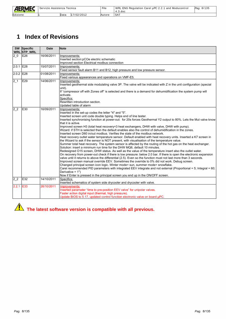
1 Index of Revisions SW
WRL Specific STP_WRL
Date
Note
2_0 E26 16/06/2011 Improvements: Inserted section:pCOe electric schematic Improved section Electrical modbus connection
2.0.1 E28 15/07/2011 Improvements: Fixed sensor fault alarm B11 and B12, high pressure and low pressure sensor.
2.0.2 E28 01/08/2011 Improvements: Fixed various appearances and operations on VMF-E5.
2_1 E29 14/06/2011 Improvements: Inserted geothermal side modulating valve 3P. The valve will be indicated with Z in the unit configuration (special unit). If “compressor off with Zones off” is selected and there is a demand for dehumidification the system pump will activate. Specifics: Rewritten introduction section. Updated table of alarm
2_2 E30 16/09/2011 Improvements: Inserted in the set-up codes the letter "4" and "5". Inserted screen unit code double typing. Helps end of line tester. Inserted synchronising function at power-out: for 20s forces Geothermal Y2 output to 80%. Lets the Mut valve know that it is active. Improved screen H3 (total heat recovery=3 heat exchangers, DHW with valve, DHW with pump). Wizard: if STH is selected then the default enables also the control of dehumidification in the zones. Inserted screen D60 in/out modbus. Verifies the state of the modbus network. Heat recovery outlet water temperature sensor. Default enabled with heat recovery units. Inserted a K7 screen in the Wizard to ask if the sensor is NOT present, with visualisation of the temperature value. Summer total heat recovery. The system sensor is affected by the routing of the hot gas on the heat exchanger. Solution: insert a minimum run time for the DHW MQ6, default 10 minutes. Redesigned O15 screen, DHW status. As well as the value of the temperature insert also the outlet water. On recovery from power-out check if there is low pressure: below 2.0 bar. If there is open the electronic expansion valve until it returns to above the differential (2.5). Even so the function must not last more than 3 seconds. Improved screen manual override EEV. Sometimes the override to 0% did not work. Debug screen. Changed principal screen icon logic. Winter mode= sun, summer mode= snowflake. Carel recommended PID parameters with integrated EEV integrate and not external (Proportional = 5; Integral = 60; Derivative = 1") Now if Enter is pressed in the principal screen you end up in the ON/OFF screen.
2_2 E32 14/10/2011 Specifics: Inserted schematics of system side drycooler and drycooler with valve.
2.2.1 E33 26/10/2011 Improvements: Inserted parameter “time to pre-position EEV valve” for unipolar valves. Faster action digital input (thermal, high pressure). Update BIOS to 5.17, updated control function electronic valve on board µPC.
The latest software version is compatible with all previous.

Servizio Assistenza Tecnica File WRL ENG Regulation Carel µPC 2.2.1 and Moducontrol
4.3.doc Pag. 9/135
Edizione 1 Data 17/02/2012 Autore SAT
Pag. 9/135 Pag. 9/135
2 Introduction The electronic controller fitted to the WRL (Water Refrigerant series L) unit contains the most important functions typical of Aermec water/water chillers. It has a whole series of functions designed to promote energy saving, such as:
- Stepped temperature control of the heat exchanger’s inlet/outlet water temperature - Proportional and integral control - Compressor rotation based on hours run - Operation of the primary and secondary pumps - Outdoor temperature based setpoint compensation (temperature sensor kit KSAE) - Seasonal change based on external temperature or calendar - Daily/weekly time-clock - Intelligent control of domestic hot water (DHW) production with desuperheater, bypass valve or double pump - Anti-legionella control through an immersion heater - Geothermal freecooling control - Solar heating control producing hot water for the system as well as DHW - Operation of a supplementary boiler only during critical periods of the year
The software developed and tested entirely by Aermec’s laboratory ensures the unit’s safety functions: - Monitors pump and compressor thermal cut-out - Anti-freeze function with the unit in standby mode - Pressure transducers in the evaporating and condensing sides provide low and high pressure control - Alarms (all displayed) can be automatic, semi-automatic or manual reset based on importance - All faults are recorded in the history log with the state of the unit at the time of alarm
Through an intuitive graphical interface the WRL unit shows the user the status of the various devices, sensors, etc., and allows a simple auto-assisted configuration (Wizard). A series of remote controlled options are additionally available:
- Remote control panel with main functions (accessory) - Volt free contacts for remote monitoring of the system or DHW - Double setpoint for both summer and winter preset in the menu - RS485 serial interface with ModBus protocol (AER485P1 accessory)
The WRL unit can control the air-conditioning of 3 environments (zones) with radiant floors - Each zone can have a dehumidifier, a circulating pump, a water temperature sensor and a mixing valve - Each zone can have up to two rooms except for Zone 1 which can have only one room - Each room will have a room sensor (STA -> th-tune) with an internal temperature sensor and a humidity sensor (optional)
WRL Schematic installation
Hardware characteristics
- From 40 to 170kW output - Refrigerant type R410a - Possibility to produce chilled and/or hot water - DHW up to 50°C water temperature - Total heat recovery - Replaces the old series NBW water/water chiller - Control of radiant zones with temperature profiles and dewpoint control
Servizio Assistenza Tecnica File WRL ENG Regulation Carel µPC 2.2.1 and Moducontrol
4.3.doc Pag. 10/135
Edizione 1 Data 17/02/2012 Autore SAT
Pag. 10/135 Pag. 10/135
-
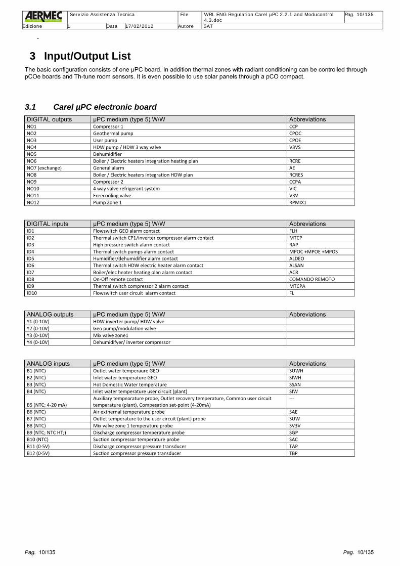
3 Input/Output List The basic configuration consists of one µPC board. In addition thermal zones with radiant conditioning can be controlled through pCOe boards and Th-tune room sensors. It is even possible to use solar panels through a pCO compact.
3.1 Carel µPC electronic board DIGITAL outputs µPC medium (type 5) W/W Abbreviations NO1 Compressor 1 CCP NO2 Geothermal pump CPOC NO3 User pump CPOE NO4 HDW pump / HDW 3 way valve V3VS NO5 Dehumidifier NO6 Boiler / Electric heaters integration heating plan RCRE NO7 (exchange) General alarm AE NO8 Boiler / Electric heaters integration HDW plan RCRES NO9 Compressor 2 CCPA NO10 4 way valve refrigerant system VIC NO11 Freecooling valve V3V NO12 Pump Zone 1 RPMIX1 DIGITAL inputs µPC medium (type 5) W/W Abbreviations ID1 Flowswitch GEO alarm contact FLH ID2 Thermal switch CP1/inverter compressor alarm contact MTCP ID3 High pressure switch alarm contact RAP ID4 Thermal switch pumps alarm contact MPOC +MPOE +MPOS ID5 Humidifier/dehumidifier alarm contact ALDEO ID6 Thermal switch HDW electric heater alarm contact ALSAN ID7 Boiler/elec heater heating plan alarm contact ACR ID8 On‐Off remote contact COMANDO REMOTO ID9 Thermal switch compressor 2 alarm contact MTCPA ID10 Flowswitch user circuit alarm contact FL ANALOG outputs µPC medium (type 5) W/W Abbreviations Y1 (0‐10V) HDW inverter pump/ HDW valve Y2 (0‐10V) Geo pump/modulation valve Y3 (0‐10V) Mix valve zone1 Y4 (0‐10V) Dehumidifyer/ inverter compressor ANALOG inputs µPC medium (type 5) W/W Abbreviations B1 (NTC) Outlet water temperaure GEO SUWH B2 (NTC) Inlet water temperature GEO SIWH B3 (NTC) Hot Domestic Water temperature SSAN B4 (NTC) Inlet water temperature user circuit (plant) SIW
B5 (NTC; 4‐20 mA) Auxiliary tempearature probe, Outlet recovery temperature, Common user circuit temperature (plant), Compesation set‐point (4‐20mA)
‐‐‐
B6 (NTC) Air exthernal temperature probe SAE B7 (NTC) Outlet temperature to the user circuit (plant) probe SUW B8 (NTC) Mix valve zone 1 temperature probe SV3V B9 (NTC; NTC HT;) Discharge compressor temperature probe SGP B10 (NTC) Suction compressor temperature probe SAC B11 (0‐5V) Discharge compressor pressure transducer TAP B12 (0‐5V) Suction compressor pressure transducer TBP

Servizio Assistenza Tecnica File WRL ENG Regulation Carel µPC 2.2.1 and Moducontrol
4.3.doc Pag. 11/135
Edizione 1 Data 17/02/2012 Autore SAT
Pag. 11/135 Pag. 11/135
3.2 Carel pCOe expansion board
Carel pCOe boards are sensitive to the power supply polarity: G with G and G0 with G0, with the Carel µPC “mother” board.
pCOe accessory Zone 2 (Modbus Address 11)
pCOe accessory Zone 3 (Modbus Address 12)
DIGITAL outputs NO1 Pump Zone 2 Pump Zone 3 NO2 Output room 2 Output room 4 NO3 Output room 3 Output room 5 NO4 Output dehumidifier zone 2 Output dehumidifier zone 3 DIGITAL inputs ID1 Thermal switch pump Zone 2 Thermal switch pump Zone 3 ID2 Alarm dehumidifier 2 Alarm dehumidifier 3 ID3 On/Off remote zone 2 On/Off remote zone 3 ID4 ANALOG outputs Y1 (0‐10V) Mix valve Zone 2 Mix valve Zone 3 ANALOG inputs B1 (NTC) Temperature Mix valve Zone 2 Temperature Mix valve Zone 3 B2 (NTC) B3 (NTC) B4 (NTC)
pCOe accessory (Modbus Address 10) DIGITAL outputs NO1 Drycooler pump NO2 NO3 NO4 DIGITAL inputs ID1 General alarm ID2 Remote contact Heating/Cooling
ID3 Economy mode (2nd Set‐point) Open=ECO
ID4 HDW priority by digital input ANALOG outputs Y1 (0‐10V) Drycooler valve ANALOG inputs B1 (NTC) B2 (NTC) B3 (NTC;) B4 (NTC;)
NO2 NO3 NO4NO1Neutro
Fase
B1
VG0
Y1
ID1 ID2 ID3
24 Vac 24 Vdc
0

Servizio Assistenza Tecnica File WRL ENG Regulation Carel µPC 2.2.1 and Moducontrol
4.3.doc Pag. 12/135
Edizione 1 Data 17/02/2012 Autore SAT
Pag. 12/135 Pag. 12/135
3.3 Carel pCO Compact board for Solar Panel
Currently only available on specific request as a unit special at order stage of the unit pCO Compact (Modbus address 16) DIGITAL outputs NO1 Pump 1 NO2 Pump 2
NO3 3 way valve to select User circuit (plant) or Sanitary system (DHW)
DIGITAL outputs ID1 Thermal switch Pump 1 ID2 Thermal switch Pump 2 ANALOG outputs Y1 (PWM) Y2 (0‐10V) Inverter Pump 1 ANALOG inputs
B1 (NTC) Inlet water temperaure from User circuit (plant) (B4)
B2 (NTC) Sanitary water temperature DHW (B3) B3 (PT1000) Solar collector probe B4 (NTC)

Servizio Assistenza Tecnica File WRL ENG Regulation Carel µPC 2.2.1 and Moducontrol
4.3.doc Pag. 13/135
Edizione 1 Data 17/02/2012 Autore SAT
Pag. 13/135 Pag. 13/135
3.4 Electrical schematic for Carel pCOe expansion board (accessory)
3.4.1.1 Carel pCOe board for control of Zone 2 and Zone 3 (an expansion board is required for each zone to be controlled)
Dip-switch configuration Zone 2 -> Zone 3 ->
ON 1 2 3 4
ON 1 2 3 4
B1
VG0
Y1 (0/10Vdc optoisolated)
ID1 ID2 ID3
24 Vac 0Vac
Room 1 Valve Zone Pump
1.5 mm2 (AWG 16) max 30m
MAX 230V-2A MAX 230V-2A MAX 230V-2A MAX 230V-2A
Room 2 Valve Dehumidifier
Zone water temperaturesensor (max length 30m)
Zone pump circuit breaker
Water mixing valve
Zone dehumidifier circuit breaker
Zone ON/OFF switch
pCOe Power

Servizio Assistenza Tecnica File WRL ENG Regulation Carel µPC 2.2.1 and Moducontrol
4.3.doc Pag. 14/135
Edizione 1 Data 17/02/2012 Autore SAT
Pag. 14/135 Pag. 14/135
3.4.1.2 Carel pCOe board for control of Drycooler system and items
Dip-switch configuration Accessory
B1
VG0
Y1 (0/10Vdc optoisolated)
ID1 ID2 ID3
24 Vac 0Vac
Drycooler Pump
1.5 mm2 (AWG 16) max 30m
MAX 230V-2A
Drycooler water temperature sensor (max length 30m)
General alarm Drycooler Valve
Summer / Winter selection
Second set selection (Economy)
pCOe Power
DHW forced priority
ON 1 2 3 4
CAREL
Servizio Assistenza Tecnica File WRL ENG Regulation Carel µPC 2.2.1 and Moducontrol
4.3.doc Pag. 15/135
Edizione 1 Data 17/02/2012 Autore SAT
Pag. 15/135 Pag. 15/135
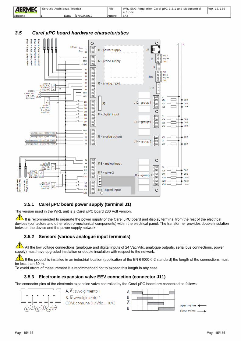
3.5 Carel µPC board hardware characteristics
3.5.1 Carel µPC board power supply (terminal J1) The version used in the WRL unit is a Carel µPC board 230 Volt version.
It is recommended to separate the power supply of the Carel μPC board and display terminal from the rest of the electrical devices (contactors and other electro-mechanical components) within the electrical panel. The transformer provides double insulation between the device and the power supply network.
3.5.2 Sensors (various analogue input terminals)
All the low voltage connections (analogue and digital inputs of 24 Vac/Vdc, analogue outputs, serial bus connections, power supply) must have upgraded insulation or double insulation with respect to the network.
If the product is installed in an industrial location (application of the EN 61000-6-2 standard) the length of the connections must be less than 30 m. To avoid errors of measurement it is recommended not to exceed this length in any case.
3.5.3 Electronic expansion valve EEV connection (connector J11) The connector pins of the electronic expansion valve controlled by the Carel µPC board are connected as follows:
Servizio Assistenza Tecnica File WRL ENG Regulation Carel µPC 2.2.1 and Moducontrol
4.3.doc Pag. 16/135
Edizione 1 Data 17/02/2012 Autore SAT
Pag. 16/135 Pag. 16/135
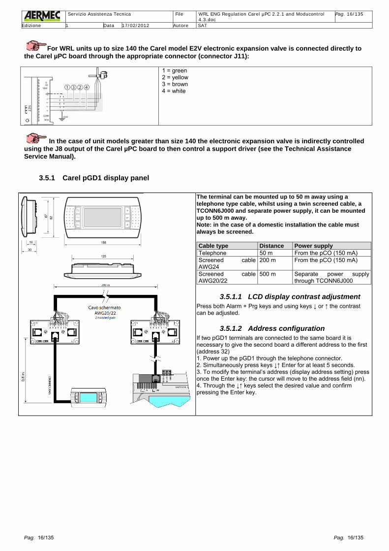
For WRL units up to size 140 the Carel model E2V electronic expansion valve is connected directly to the Carel µPC board through the appropriate connector (connector J11):
1 = green 2 = yellow 3 = brown 4 = white
In the case of unit models greater than size 140 the electronic expansion valve is indirectly controlled using the J8 output of the Carel µPC board to then control a support driver (see the Technical Assistance Service Manual).
3.5.1 Carel pGD1 display panel
The terminal can be mounted up to 50 m away using a telephone type cable, whilst using a twin screened cable, a TCONN6J000 and separate power supply, it can be mounted up to 500 m away. Note: in the case of a domestic installation the cable must always be screened. Cable type Distance Power supply Telephone 50 m From the pCO (150 mA) Screened cable AWG24
200 m From the pCO (150 mA)
Screened cable AWG20/22
500 m Separate power supply through TCONN6J000
3.5.1.1 LCD display contrast adjustment Press both Alarm + Prg keys and using keys ↓ or ↑ the contrast can be adjusted.
3.5.1.2 Address configuration If two pGD1 terminals are connected to the same board it is necessary to give the second board a different address to the first (address 32) 1. Power up the pGD1 through the telephone connector. 2. Simultaneously press keys ↓↑ Enter for at least 5 seconds. 3. To modify the terminal’s address (display address setting) press once the Enter key: the cursor will move to the address field (nn). 4. Through the ↓↑ keys select the desired value and confirm pressing the Enter key.

Servizio Assistenza Tecnica File WRL ENG Regulation Carel µPC 2.2.1 and Moducontrol
4.3.doc Pag. 17/135
Edizione 1 Data 17/02/2012 Autore SAT
Pag. 17/135 Pag. 17/135
4 Unit configuration code 1 2 3 4 5 6 7 8 9 10 11 12 13 14 15 WRL Size Field of
use Model Version Heat
Recovery Geo pump
User pump
Recovery pump
Soft start
Power supply
WRL SIZE 025 - 030 - 040 - 050 - 070 - 080 - 100 - 140 – 160
180-200-300-400-500-550-600-650
FIELD OF USE ° - Standard with leaving water above +4°C Y – Low temperature with leaving water down to -6°C X – Electronic expansion valve (EEV) with leaving water down to -8°C
MODEL ° - Cooling (Reversible water-side) H – Heat pump (Reversible refrigerant circuit) E – Evaporating unit (not available for heat pump versions)
VERSION ° - Standard A – With system buffer tank
HEAT RECOVERY
° - Without heat recovery D - Desuperheater (ONLY FOR COOLING ONLY VERSION) T- With total heat recovery (ONLY FOR HEAT PUMP VERSIONS a variable flow Pump is recommended to be installed on the geothermal side)
GEOTHERMIC SIDE PUMP
° - Without pump B – ON-OFF circulator with 3 speeds (models up to size 080) Low head pump (models above size 080) U – High head pump (models above size 080) F – Pump suitable for phase shaving (models up to size 080) I – Inverter pump high head (models up to size 080) V – Modulating throttling valve
USER SIDE PUMP
Evaporator in cooling mode ° - Without pump P – ON-OFF circulator with 3 speeds (models up to size 080) Low head pump (models above size 080) J – ON-OFF high head circulator with 3 speeds(for WRL models see section 2.3 for sizes 025-030-040) N – High head pump (models above size 080, or for WRL models see section 2.3 for sizes from 050 to 160)
RECOVERY SIDE PUMP
° - Without DHW pump Q – With DHW pump
SOFT-START ° - Without compressor soft-start S – With compressor soft-start
POWER SUPPLY ° - 400V 3N~ 50Hz M - 230V ~ 50Hz (only model sizes 025, 030, 040) 4 – 230V – 3 – 50Hz (only model sizes 050, 070, 080, 100, 140, 160) 5 – 500V – 3 – 50Hz (only model sizes 400, 550, 600, 650)
4.1 Accessories Item Description of accessory
PGD1 Remote display panel. Remote mount up to 500 m with TWISTED SCREENED 2 PAIRS to two screened TCONN6J000.
KSAE Outdoor air sensor. Temperature sensor with plastic enclosure. AER485P1 RS-485 interface for monitoring systems with MODBUS protocol. VT Anti-vibration mounts. Group of four anti-vibration mounts for installation under the unit’s steel base. STA Installation kit of 230Vac. Contains a room thermostat with temperature sensor, display and setpoint adjuster.
STH Installation kit of 230Vac. Contains a room thermostat with temperature sensor, humidity sensor, display and setpoint adjuster.
SSM Water temperature clamp on sensor for the zone mixing valves. Kit consists of only one sensor. S...I System tank; available in sizes 290, 300, 400 and 500 litres (S200I, S300I, S400I and S500I). VMFCRP: Control of Zone 2 or control of Zone 3. A Carel pCOe board is contained within.

Servizio Assistenza Tecnica File WRL ENG Regulation Carel µPC 2.2.1 and Moducontrol
4.3.doc Pag. 18/135
Edizione 1 Data 17/02/2012 Autore SAT
Pag. 18/135 Pag. 18/135
4.2 DHW typology, see Menu Wizard paragraph password 0303 screen K6
OR: Total recovery Priority + Pump Priority + Valve
Location of accessories Legend: Geo: Geothermal system side System: user system side Sanit.: DHW system side SSAN: DHW tank sensor KSAE: outdoor air sensor Zone 1: controlled directly from the Carel µPC board SSM: Zone 1 mixed circuit temperature sensor, controlled directly from the Carel µPC board STA/H1 Zone 1: space temperature/humidity sensor; if the system has only one zone it is controlled directly from the Carel µPC board VMF CRP*: for control of Zone 2 or Zone 3 (a pCOe expansion board is required for each zone) * STA/H 1 and 2 for Zone 2: space temperature/humidity sensors; if the system has two zones a further two space temperature/humidity sensors can be controlled (one for each room in Zone 2, adding the VMF CRP accessory) – see successive sections * STA/H 1 and 2 for Zone 3: space temperature/humidity sensor; if the system has three zones a further two space temperature/humidity sensors can be controlled (one for each room in Zone 3 adding a further VMF CRP accessory) – see successive sections
Impianto
SSAN↓
Geo
Sanit
Impianto
SSAN ↓
Geo
Sanit.
Impianto
SSAN↓
Geo
Sanit.
SSM ↓
Zone 1
Geo
KSAE
PGD1
STA/H
WRL pCOe
VMFCRP

Servizio Assistenza Tecnica File WRL ENG Regulation Carel µPC 2.2.1 and Moducontrol
4.3.doc Pag. 19/135
Edizione 1 Data 17/02/2012 Autore SAT
Pag. 19/135 Pag. 19/135
5 ModBus Network The Carel µPC board does not have sufficient inputs and outputs to cover all functions.
Thanks to a port named “Field Bus”, terminal J10 of the board, “the application” is capable of controlling various slave boards in ModBus protocol (Carel pCOe expansion board).
5.1 Table of devices controlled on the ModBus network
The devices installed must all be connected to the ModBus serial network.
Remember to install a 120 Ohm resistor between Tx+ and Tx- at the beginning and end of the serial network
Address Device connected
1
Zone 1, Room 1 directly controlled from the Carel µPC board
2 Zone 2, Room 1 (STA/H) 3 Zone 2, Room 2 (STA/H) 4 Zone 3, Room 1 (STA/H) 5 Zone 3, Room 2 (STA/H) 10 pCOe Accessory 11 pCOe Zone 2 12 pCOe Zone 3 16 Solar kit pCO compact
To address the Carel pCOe boards it is sufficient to change the dip-switches of the expansion boards. To address the STA/H (TH-Tune) room sensor requires: - Power up the device - Press keys FAN+POWER for 3s. - Enter the password 22 turning the “Push button” - Change the “Addr” parameter - Go to the “ESC” parameter and push the “Push button”
5.2 Complete ModBus electrical connection
GN
D
T+ T
ON 1 2 3 4
Accessory
Add4
GN
D
T+ T
ON 1 2 3 4
Zone 3 Zone 3
Add5
Zone 3
GN
D
Tx+ T230V
CA
RE
L D
ata 06 N
S:N
. A001
RO
HS
A
TA
GN
D
Tx+ T230V
CA
RE
L D
ata 06 N
S:N
. A001
RO
HS
A
TA
GN
DT+ T- V
t
µPC
Add1
screened cable
GN
DTx+ T230V
CA
RE
L D
ata 06 N
S:N
. A001
RO
HS
A
TA
GN
DT+ T
ON 1 2 3
Zone 2 Zone 2
Zone 1
Add2
Add3
Zone 2
GN
DTx+ T230V
CA
RE
L D
ata 06 N
S:N
. A001
RO
HS
A
TA
GN
DTx+ T230V
CA
RE
L D
ata 06 N
S:N
. A001
RO
HS
A
TA

Servizio Assistenza Tecnica File WRL ENG Regulation Carel µPC 2.2.1 and Moducontrol
4.3.doc Pag. 20/135
Edizione 1 Data 17/02/2012 Autore SAT
Pag. 20/135 Pag. 20/135
6 Examples of hydraulic systems possible with the WRL unit With appropriate configuration of the parameters contained in the Menu Wizard password 0303 and Menu Set-up procedure password 0009; it is possible to obtain various hydraulic system configurations achievable with the WRL unit.
6.1 Cool only with freecooling (example WRL160X°°BP°S°)
6.2 Cool only with desuperheater (example WRL160X°°DBPQS°)
GEO
NO1 ID2
NO8 ID6
NO9 ID9
NO2 ID4
NO3 ID4
B1
B2
B4
B7
NO4 ID4
B3
NO6 ID7
GEO
NO1 ID2
NO9 ID9
NO2 ID4
NO3 ID4
B2 B7
NO11
Freecooling
B4 B1 System
System

Servizio Assistenza Tecnica File WRL ENG Regulation Carel µPC 2.2.1 and Moducontrol
4.3.doc Pag. 21/135
Edizione 1 Data 17/02/2012 Autore SAT
Pag. 21/135 Pag. 21/135
6.3 Heat/cool with refrigerant circuit reversing (example WRL160XH°°BP°S°)
6.4 Heat/cool with refrigerant circuit reversing + total heat recovery (example WRL160XH°TBPQS°)
\
B5*= optional heat recovery outlet sensor, available from software version 1.9
GEO
NO1 ID2
NO9 ID9
NO2 ID4
NO3 ID4 B1
B2 NO10
B7
NO6 ID7
Y2
B4 pCOE 2
pCOE 1
ZONE 1 NO12 ID4 B8 Y3
ZONE 2
ZONE 3
GEO
B3
NO1 ID2
NO9 ID9
NO2 ID4
NO3 ID4
B1
B2
NO10
B7
NO6 ID7
NO4 ID4
NO8 ID6
Y1
Y2
B4 pCOE 2
pCOE 1
ZONE 1 NO12 ID4 B8 Y3
ZONE 2
ZONE 3
B5*

Servizio Assistenza Tecnica File WRL ENG Regulation Carel µPC 2.2.1 and Moducontrol
4.3.doc Pag. 22/135
Edizione 1 Data 17/02/2012 Autore SAT
Pag. 22/135 Pag. 22/135
6.5 Heat/cool refrigerant circuit reversing, DHW + 3 way valve (example WRL160XH°°BP°S°)
In the Menu Wizard password 0303, enter on screen K6: DHW with valve
6.6 Heat/cool refrigerant circuit reversing, DHW with pump (example WRL160XH°°BP°S°)
In the Menu Wizard password 0303, enter on screen K6: DHW with pump
GEO
NO1ID2
NO9 ID9
NO2 ID4 Y2
NO3 ID4
B1
B2
NO1
B7
NO6 ID7
NO8 ID6NO4
ID4
B4 pCOE 2
pCOE 1
ZONE 1 NO12 ID4 B8 Y3
ZONE 2
ZONE 3
B3
GEO
NO1 ID2
NO9 ID9
NO2 Y2 ID4
NO3 ID4 B1
B2
NO10
B7
NO6 ID7
NO8 ID6
NO 4
B4 pCOE 2
pCOE 1
ZONE 1 NO12 ID4 B8 Y3
ZONE 2
ZONE 3
B3

Servizio Assistenza Tecnica File WRL ENG Regulation Carel µPC 2.2.1 and Moducontrol
4.3.doc Pag. 23/135
Edizione 1 Data 17/02/2012 Autore SAT
Pag. 23/135 Pag. 23/135
NO4 ID4
NO2 ID4 Y2
NO2 ID4 Y2
6.7 Heat/cool water-side reversing (example WRL160X°°°BP°S°)
6.8 Drycooler with heat exchanger
Installation of Carel pCOe board accessory is required (address 10)
6.9 Drycooler system side
Installation of Carel pCOe board accessory is required (address 10)
NO6 ID7
GEO
NO1 ID2
NO9 ID9
NO2 ID4 Y2
NO3 ID4
B2 NO4 ID4
B1
B7
B4
Evaporation
Condenser System
System
System
NO1 ID2
NO9 ID9
NO3 ID4
B1
B2
B4
B7
NO1 pCoE
B1 pCOE
Y1 pCOE
Y1 pCOE
NO1 ID2
NO9 ID9
NO3 ID4
B1
B2 B7
B4
NO1 pCoE
B1 pCOE

Servizio Assistenza Tecnica File WRL ENG Regulation Carel µPC 2.2.1 and Moducontrol
4.3.doc Pag. 24/135
Edizione 1 Data 17/02/2012 Autore SAT
Pag. 24/135 Pag. 24/135
NO2 ID4 Y2
6.10 Drycooler with valve
Installation of Carel pCOe board accessory is required (address 10)
6.11 Hydraulic schematic with Solar Kit and Freecooling
Installation of additional Carel pCO Compact accessory board is required
System
DHW
S3
pCO Compact
B3
P2V1 P1
S2
NO3
GEO
NO2 Y2
NO3
B7 B2
B1 S1
Chiller
Freecooling
NO11
B4
System
B1 pCOe
NO1 ID2
NO9 ID9
NO3 ID4
B1
B2
B4
B7 Y1 pCOE
NO1 pCoE
Servizio Assistenza Tecnica File WRL ENG Regulation Carel µPC 2.2.1 and Moducontrol
4.3.doc Pag. 25/135
Edizione 1 Data 17/02/2012 Autore SAT
Pag. 25/135 Pag. 25/135
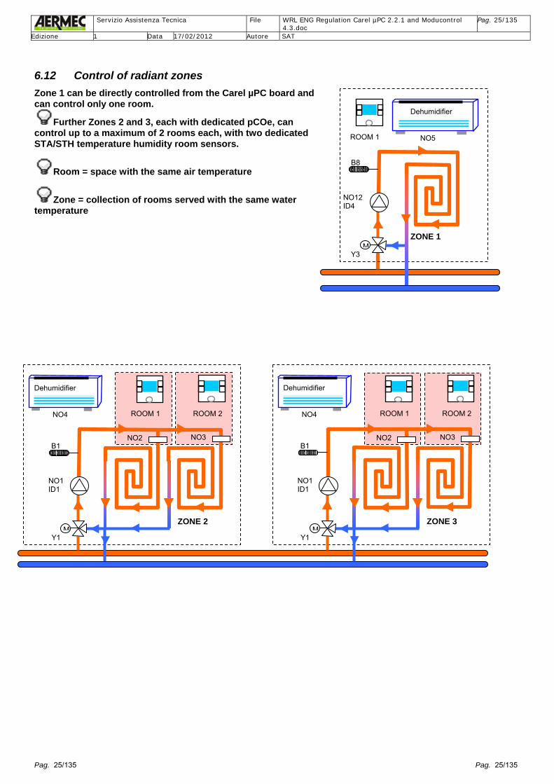
6.12 Control of radiant zones Zone 1 can be directly controlled from the Carel µPC board and can control only one room.
Further Zones 2 and 3, each with dedicated pCOe, can control up to a maximum of 2 rooms each, with two dedicated STA/STH temperature humidity room sensors.
Room = space with the same air temperature
Zone = collection of rooms served with the same water temperature
Y1
NO1ID1
B1
ROOM 1
ZONE 2 M
NO4
Dehumidifier
ROOM 2
NO2 NO3
Y1
NO1ID1
B1
ROOM 1
ZONE 3 M
NO4
Dehumidifier
ROOM 2
NO2 NO3
Y3
NO12ID4
B8
ROOM 1
ZONE 1 M
NO5
Dehumidifier

Servizio Assistenza Tecnica File WRL ENG Regulation Carel µPC 2.2.1 and Moducontrol
4.3.doc Pag. 26/135
Edizione 1 Data 17/02/2012 Autore SAT
Pag. 26/135 Pag. 26/135
7 Navigation of the Menus and sub-menus of the controller
Use the “arrow” buttons to move within various sub-menus, use the “enter” button to enter the chosen sub-menu.
Use the “enter” bottom to move to the 0-0-0-0 position of the password, use the “arrow” button to modify the combination, finally when the password needed to access the required menu is entered, confirm with “enter”.
See on page 38

Servizio Assistenza Tecnica File WRL ENG Regulation Carel µPC 2.2.1 and Moducontrol
4.3.doc Pag. 27/135
Edizione 1 Data 17/02/2012 Autore SAT
Pag. 27/135 Pag. 27/135
MENU WIZARD, See on page 31 MENU SET UP PROCEDURE, See on page 35 MENU SERVICE, See on page 47 FACTORY MENU, See on page 67
IMPORTANT: From software version 2.3.0 it is possible to directly access the Assistance sub-menu of the Menu User simply by pressing the key. The access method to the Menu User sub-menus and to the Menus Wizard (password 0303), Set-up procedure (password 0009), Assistance (password 0101) and Manufacturer (password 0202) remain as described in the earlier screens.
Menu Service
FACTORY Menu
Servizio Assistenza Tecnica File WRL ENG Regulation Carel µPC 2.2.1 and Moducontrol
4.3.doc Pag. 28/135
Edizione 1 Data 17/02/2012 Autore SAT
Pag. 28/135 Pag. 28/135
8 User interface
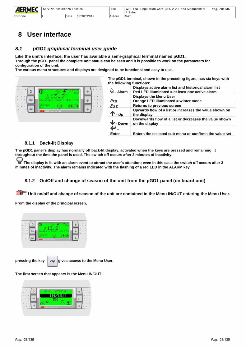
8.1 pGD1 graphical terminal user guide Like the unit’s interface, the user has available a semi-graphical terminal named pGD1. Through the pGD1 panel the complete unit status can be seen and it is possible to work on the parameters for configuration of the unit. The various menu structures and displays are designed to be functional and easy to use.
The pGD1 terminal, shown in the preceding figure, has six keys with the following functions:
- Alarm Displays active alarm list and historical alarm list Red LED illuminated = at least one active alarm Displays the Menu User Orange LED illuminated = winter mode Returns to previous screen
- Up Upwards flow of a list or increases the value shown on the display
- Down Downwards flow of a list or decreases the value shown on the display
- Enter Enters the selected sub-menu or confirms the value set
8.1.1 Back-lit Display The pGD1 panel’s display has normally off back-lit display, activated when the keys are pressed and remaining lit throughout the time the panel is used. The switch off occurs after 3 minutes of inactivity.
The display is lit with an alarm event to attract the user’s attention; even in this case the switch off occurs after 3 minutes of inactivity. The alarm remains indicated with the flashing of a red LED in the ALARM key.
8.1.2 On/Off and change of season of the unit from the pGD1 panel (on board unit)
Unit on/off and change of season of the unit are contained in the Menu IN/OUT entering the Menu User. From the display of the principal screen, pressing the key gives access to the Menu User. The first screen that appears is the Menu IN/OUT;
Servizio Assistenza Tecnica File WRL ENG Regulation Carel µPC 2.2.1 and Moducontrol
4.3.doc Pag. 29/135
Edizione 1 Data 17/02/2012 Autore SAT
Pag. 29/135 Pag. 29/135
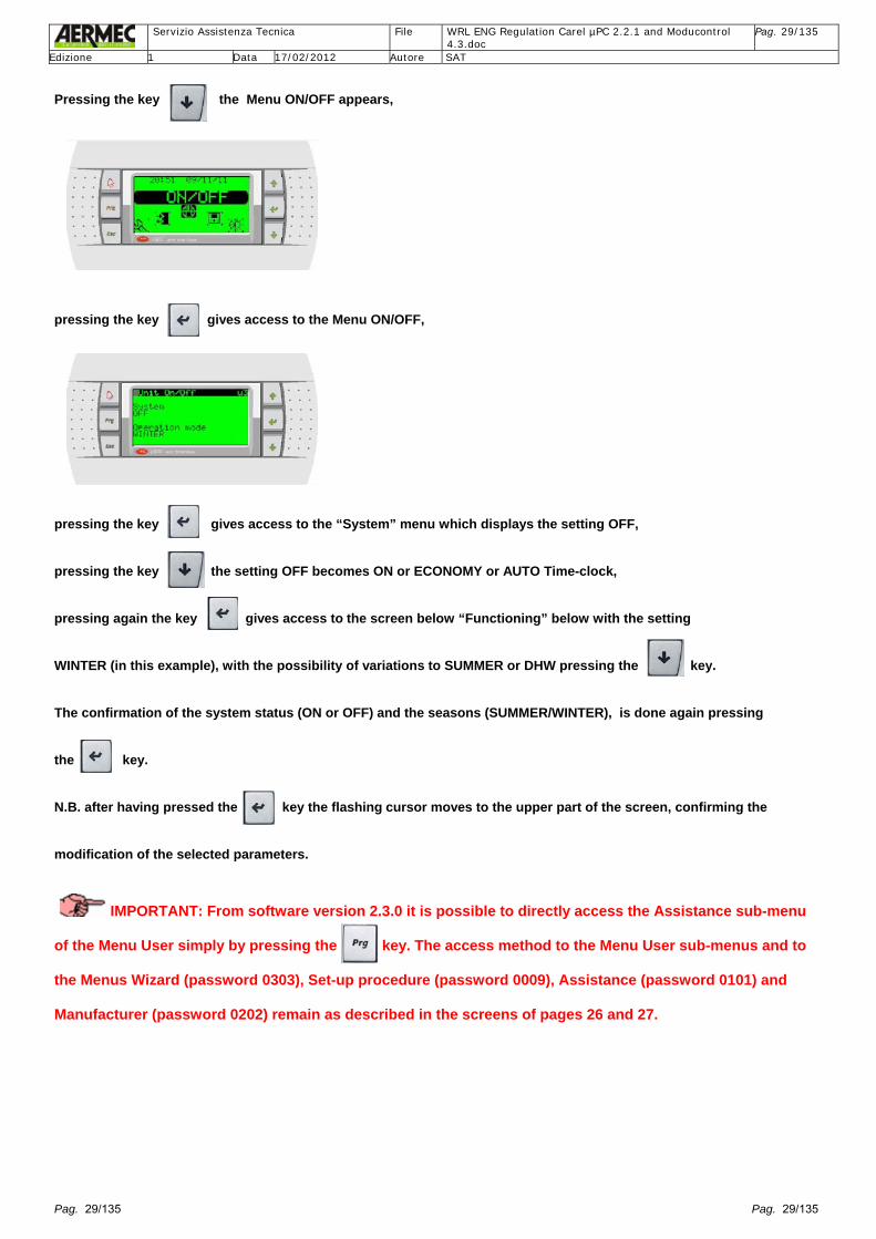
Pressing the key the Menu ON/OFF appears, pressing the key gives access to the Menu ON/OFF, pressing the key gives access to the “System” menu which displays the setting OFF, pressing the key the setting OFF becomes ON or ECONOMY or AUTO Time-clock, pressing again the key gives access to the screen below “Functioning” below with the setting WINTER (in this example), with the possibility of variations to SUMMER or DHW pressing the key. The confirmation of the system status (ON or OFF) and the seasons (SUMMER/WINTER), is done again pressing the key. N.B. after having pressed the key the flashing cursor moves to the upper part of the screen, confirming the modification of the selected parameters.
IMPORTANT: From software version 2.3.0 it is possible to directly access the Assistance sub-menu of the Menu User simply by pressing the key. The access method to the Menu User sub-menus and to the Menus Wizard (password 0303), Set-up procedure (password 0009), Assistance (password 0101) and Manufacturer (password 0202) remain as described in the screens of pages 26 and 27.
Servizio Assistenza Tecnica File WRL ENG Regulation Carel µPC 2.2.1 and Moducontrol
4.3.doc Pag. 30/135
Edizione 1 Data 17/02/2012 Autore SAT
Pag. 30/135 Pag. 30/135
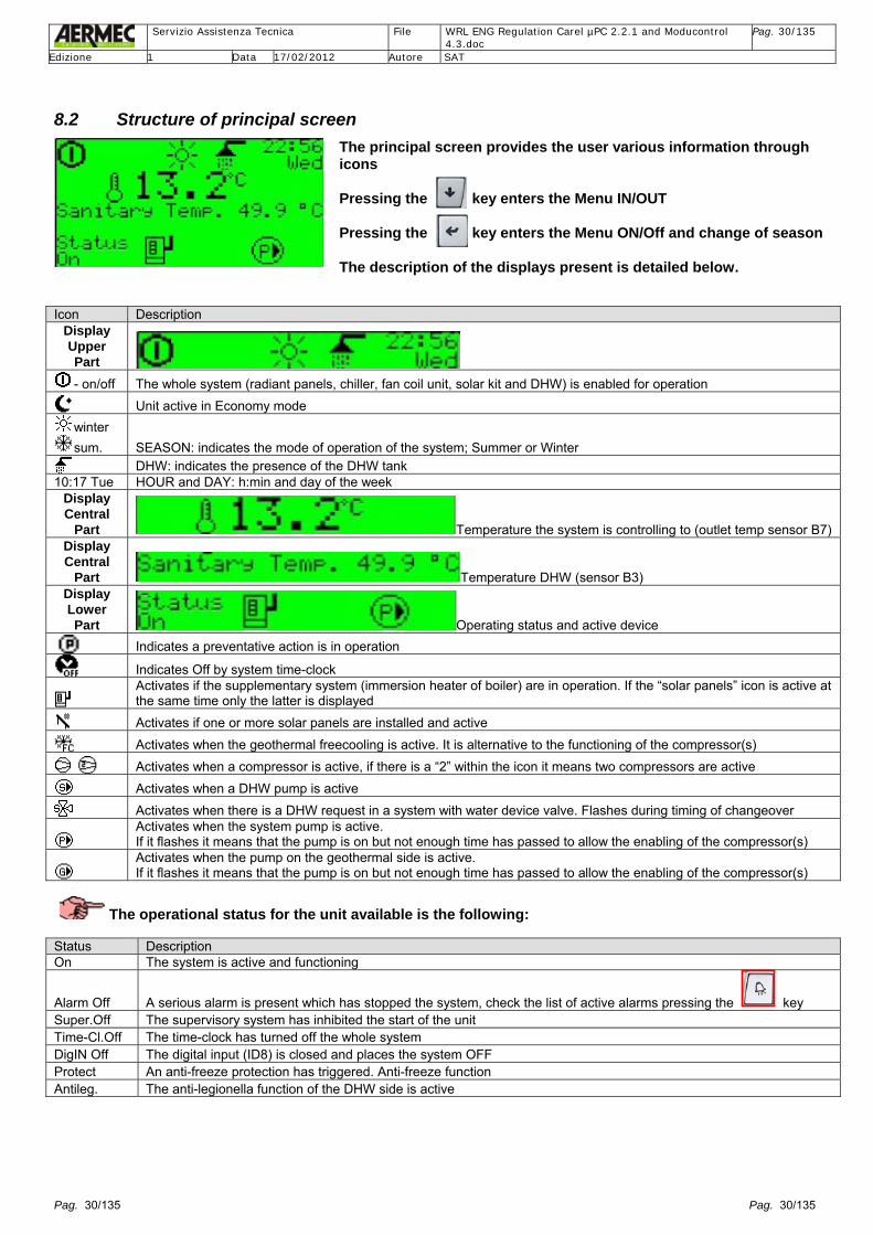
8.2 Structure of principal screen
The principal screen provides the user various information through icons Pressing the key enters the Menu IN/OUT Pressing the key enters the Menu ON/Off and change of season The description of the displays present is detailed below.
Icon Description
Display Upper Part - on/off The whole system (radiant panels, chiller, fan coil unit, solar kit and DHW) is enabled for operation
Unit active in Economy mode winter sum. SEASON: indicates the mode of operation of the system; Summer or Winter DHW: indicates the presence of the DHW tank
10:17 Tue HOUR and DAY: h:min and day of the week Display Central
Part Temperature the system is controlling to (outlet temp sensor B7) Display Central
Part Temperature DHW (sensor B3) Display Lower Part Operating status and active device
Indicates a preventative action is in operation
Indicates Off by system time-clock
Activates if the supplementary system (immersion heater of boiler) are in operation. If the “solar panels” icon is active at the same time only the latter is displayed
Activates if one or more solar panels are installed and active
Activates when the geothermal freecooling is active. It is alternative to the functioning of the compressor(s)
Activates when a compressor is active, if there is a “2” within the icon it means two compressors are active
Activates when a DHW pump is active
Activates when there is a DHW request in a system with water device valve. Flashes during timing of changeover
Activates when the system pump is active. If it flashes it means that the pump is on but not enough time has passed to allow the enabling of the compressor(s)
Activates when the pump on the geothermal side is active. If it flashes it means that the pump is on but not enough time has passed to allow the enabling of the compressor(s)
The operational status for the unit available is the following: Status Description On The system is active and functioning
Alarm Off A serious alarm is present which has stopped the system, check the list of active alarms pressing the key Super.Off The supervisory system has inhibited the start of the unit Time-Cl.Off The time-clock has turned off the whole system DigIN Off The digital input (ID8) is closed and places the system OFF Protect An anti-freeze protection has triggered. Anti-freeze function Antileg. The anti-legionella function of the DHW side is active

Servizio Assistenza Tecnica File WRL ENG Regulation Carel µPC 2.2.1 and Moducontrol
4.3.doc Pag. 31/135
Edizione 1 Data 17/02/2012 Autore SAT
Pag. 31/135 Pag. 31/135
9 Menu Wizard (password 0303) To speed up the WRL unit start-up it is possible to use the following start-up procedure.
Mask Description
At first power up the selection of the available languages is asked “see language section” and the password will be requested
This screen appears after the first power up of the unit and can be returned to Press the Prog key and enter the Menu Service then press Enter and enter the password 0303
As long as the configuration Wizard is not completed an alarm will be generated (not history logged)
Procedure to enter the Menu Wizard in the case of checking or modifying the configuration entered during the start-up of the unit: press the key to move to screen continue to press to arrive at the screen
0303

Servizio Assistenza Tecnica File WRL ENG Regulation Carel µPC 2.2.1 and Moducontrol
4.3.doc Pag. 32/135
Edizione 1 Data 17/02/2012 Autore SAT
Pag. 32/135 Pag. 32/135
Once in the Menu Wizard it is possible to run though the list of screens using the keys and . The chosen screen is selected pressing the key. To modify the parameter(s) or content(s) of the screen use the key and to modify the parameter(s) use the and keys. To confirm the required modification press the key.
Mask Description Values descriptions D e f
M i n
M a x
Select if a DHW tank is present and how it is controlled
0. NOT PRESENT 1. TOTAL RECOVERY (N.B. forced if digit T is inserted in the Menu start-up procedure password 0009) 2. PRIORITY.+ VALVE = DHW with valve 3. PRIORITY + PUMP = DHW with twin pump
0 1 3
The units with total heat recovery built after May 2011 have a sensor mounted in the heat exchanger. To simplify selection the value of the sensor is displayed
The unit will produce hot water based on the outlet heat recovery temperature and only if requested by the DHW tank sensor
0 0 1
Selects if the system pump is before or after the water-side reversing valve. Displayed if unit with water-side reversing
0. UPSTREAM 1. DOWNSTREAM
0 0 1
Outdoor temperature present 0. NO 1. YES
0 1 0
Geothermal freecooling capability 0. NO 1. YES
0 1 0
Solar panel heating control capability 0. NO 1. YES
0 1 0
Select supplementary system heating
0. NONE 1. BOILER 2. HEATING EL.
0 1 2
Method of supplementary heating --- 0: Hp INTEGRATION 1: Hp REPLACEMENT
0 1 1
Select DHW supplementary heating. If immersion heater is chosen it enables the anti-legionella function
0. NONE 1. BOILER 2. HEATING EL.
0 1 2
Method of DHW supplementary heating
--- 0: Hp INTEGRATION 1: Hp REPLACEMENT
0 1 1
In the case of a mixed system the device requiring the hottest water temperature must be indicated. NB: in the case of a system with fan coil unitsor radiators it is not intended to install the pCOe expansion boards or the STA/H temperature/humidity sensor
Value Winter Set point 0 RADIANT FLOW 35,0 1 FANCOILS 45,0 2 RADIATOR 55.0°C 3 MIX, Set 40°C 40,0
3 1 2

Servizio Assistenza Tecnica File WRL ENG Regulation Carel µPC 2.2.1 and Moducontrol
4.3.doc Pag. 33/135
Edizione 1 Data 17/02/2012 Autore SAT
Pag. 33/135 Pag. 33/135
Mask Description Values descriptions D
e f
M i n
M a x
In the case of a mixed system the device requiring the coldest water temperature must be indicated. NB: in the case of a system with fan coil units or radiators it is not intended to install the pCOe expansion boards or the STA/H temperature/humidity sensor
Type Summer set-point
Plant Antifreeze set-point
0 RADIANT FLOW 17,0 4.0 1 FANCOILS 12,0 4.0 2 RADIATOR 12,0 4.0 3 WATER GLICOLE
0% 7,0 4.0
4 WATER GLICOLE 10%
7,0 -1.0
5 WATER GLICOLE 20%
7,0 -10.0
6 WATER GLICOLE >20%
7,0 -10.0
3 0 6
With a water/glycol mix it is possible to produce lower temperatures so if a value other than 0% is used the following alarms are automatically modified: LOP (AL=91), LowTemp (AL097) = with EEV valve
Glicol % Geo Antifreeze set-point [°C]
LOP [°C]
Evap Low temperature [°C]
0) 0% 4.0 -2.0 2.0 1) 10% -1.0 -7.0 -4.0 2) 20% -10.0 -13.0 -9.0
0 0 2
Maximum number of zones that can be controlled
--- 1 0 3
Inserting 1 the Carel µPC board can directly control one zone and one room with the STA/H sensor
--- 1 0 1
In the case of other radiant zones being present inserting 2 or 3 it is necessary to install one or two pCOe expansion boards (one per zone) and to install at least one STA/H sensor per room
--- 1 0 2
Example: Number of radiant zones: 1 Number of rooms Zone 1: select 0 or 1 and the Carel µPC board can directly control one zone and one room with the STA/H sensor.
Example: Number of radiant zones: 2 Number of rooms Zone 1: select 0 or 1 Zone 2: select 0, 1 or 2
Example: Number of radiant zones: 3 Number of rooms Zone 1: select 0 or 1 Zone 2: select 0, 1 or 2 Zone 3: select 0, 1 or 2
Example: Screen complete
Zone 1 Type of device Type of sensor connected to Room 1 0. STA/H Temperature only
1. STA/H Temperature/Humidity 0 0 1
Zone 2 Type of device Type of sensor connected to Room 1 0. STA/H Temperature only
1. STA/H Temperature/Humidity 0 0 1
Type of sensor connected to Room 2 0. STA/H Temperature only 1. STA/H Temperature/Humidity
0 0 1
Servizio Assistenza Tecnica File WRL ENG Regulation Carel µPC 2.2.1 and Moducontrol
4.3.doc Pag. 34/135
Edizione 1 Data 17/02/2012 Autore SAT
Pag. 34/135 Pag. 34/135
Mask Description Values descriptions D
e f
M i n
M a x
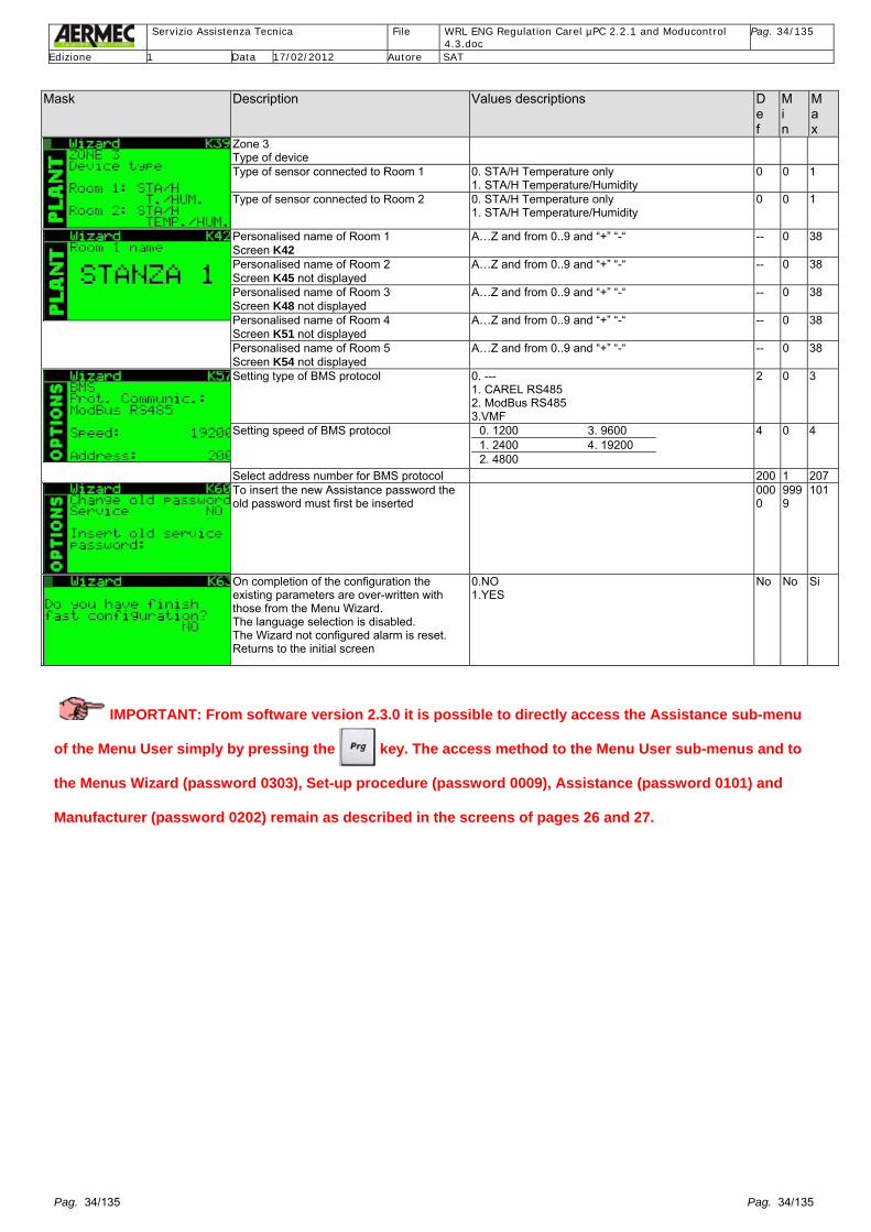
Zone 3 Type of device
Type of sensor connected to Room 1 0. STA/H Temperature only 1. STA/H Temperature/Humidity
0 0 1
Type of sensor connected to Room 2 0. STA/H Temperature only 1. STA/H Temperature/Humidity
0 0 1
Personalised name of Room 1 Screen K42
A…Z and from 0..9 and “+” “-“ -- 0 38
Personalised name of Room 2 Screen K45 not displayed
A…Z and from 0..9 and “+” “-“ -- 0 38
Personalised name of Room 3 Screen K48 not displayed
A…Z and from 0..9 and “+” “-“ -- 0 38
Personalised name of Room 4 Screen K51 not displayed
A…Z and from 0..9 and “+” “-“ -- 0 38
Personalised name of Room 5 Screen K54 not displayed
A…Z and from 0..9 and “+” “-“ -- 0 38
Setting type of BMS protocol 0. --- 1. CAREL RS485 2. ModBus RS485 3.VMF
2 0 3
Setting speed of BMS protocol
0. 1200 3. 9600 1. 2400 4. 19200 2. 4800
4 0 4
Select address number for BMS protocol 200 1 207 To insert the new Assistance password the old password must first be inserted
0000
9999
101
On completion of the configuration the existing parameters are over-written with those from the Menu Wizard. The language selection is disabled. The Wizard not configured alarm is reset. Returns to the initial screen
0.NO 1.YES
No No Si
IMPORTANT: From software version 2.3.0 it is possible to directly access the Assistance sub-menu of the Menu User simply by pressing the key. The access method to the Menu User sub-menus and to the Menus Wizard (password 0303), Set-up procedure (password 0009), Assistance (password 0101) and Manufacturer (password 0202) remain as described in the screens of pages 26 and 27.

Servizio Assistenza Tecnica File WRL ENG Regulation Carel µPC 2.2.1 and Moducontrol
4.3.doc Pag. 35/135
Edizione 1 Data 17/02/2012 Autore SAT
Pag. 35/135 Pag. 35/135
10 Menu Set Up Procedure (password 0009)
Group of hidden screens, DO NOT DIVULGE EXISTENCE.
To speed of the set-up procedure at the Aermec office this group of hidden screens were created.
If required by the Technical Assistance Service, this menu can be accessed on site where the unit is installed to verify the particular unit configuration inserted. To access this group of screens insert the password 0009 from the Menu Service. Mask Description
Press the Prog key and enter the Menu Service (see dedicated section) then press Enter and insert the password 0009 The password is always fixed at 0009 The password displayed will return to 0 after 5 minutes of inactivity of the user terminal.
Procedure to enter the Menu set-up procedure: press the key to move to screen continue to press to arrive at the screen
0009 0009

Servizio Assistenza Tecnica File WRL ENG Regulation Carel µPC 2.2.1 and Moducontrol
4.3.doc Pag. 36/135
Edizione 1 Data 17/02/2012 Autore SAT
Pag. 36/135 Pag. 36/135
Once in the Menu set-up procedure it is possible to run though the list of screens using the keys and The chosen screen is selected pressing the key. To modify the parameter(s) or content(s) of the screen use the key and to modify the parameter(s) use the and keys. To confirm the required modification press the key. Mask Description
WRL unit configuration. The unit is configured in accordance with the symbols inserted in the spaces provided. At the end of the configuration the verification of the “code” is requested. N.B.: the code and the date inserted are memorised in the Menu Info of the Menu Service password 0101.
HP: high pressure of the compressor discharge and saturated refrigerant temperature with reference to the type of refrigerant selected (for WRL unit refrigerant R410a). T. Outlet: compressor refrigerant discharge temperature. LP: evaporating pressure and saturated suction temperature with reference to the type of refrigerant selected (for WRL unit refrigerant R410a). Suction temperature and SH suction super heat are calculated.
Forced accelerated timings like: N.B. If power is removed then re-instated the timings return to default values
Forced accelerated timings like: N.B. If power is removed then re-instated the timings return to default values
System WINTER: ON/OFF of the system and select SUMMER/WINTER. Parameter the same as screen u3 (Menu ON/OFF of the Menu User). N.B.: the selection SUMMER/WINTER can only be changed with the unit off. Set. Sys. Summer: System cooling water setpoint. Parameter the same as screen S3 (Menu Chiller of the Menu User) Set.Sys.Winter: System heating water setpoint. Parameter the same as screen S6 (Menu Chiller of the Menu User)
Al. Antif. Geo: anti-freeze alarm setting of the outlet side (geothermal). Parameter the same as screen (Menu Conf. Alarm of the Menu Factory password 0202). Al. Antif. Sys.: anti-freeze alarm setting of the system side. Parameter the same as screen A6 (Menu Conf. Alarm of the Menu Factory password 0202). Al. Low Pres.: low pressure alarm setting. Parameter the same as screen A21 (Menu Conf. Alarm of the Menu Factory password 0202). Al. High Pres.: high pressure alarm setting. Parameter the same as screen A18 (Menu Conf. Alarm of the Menu Factory password 0202)
Superheat: state of the suction refrigerant super heat. State EEV: state of percentage opening of the electronic expansion valve. Valve opening at start-up: set opening of the electronic expansion valve. Forced manual: Valve forced manual with value of modification “stp” = step
Forced operation of various pumps. Forced operation of system immersion heater or DHW
Forced operation compressor 1. Forced operation compressor 2. Forced operation valve inversion cycle VIC of the refrigerant circuit. Forced operation free-cooling. Forced operation dehumidifier

Servizio Assistenza Tecnica File WRL ENG Regulation Carel µPC 2.2.1 and Moducontrol
4.3.doc Pag. 37/135
Edizione 1 Data 17/02/2012 Autore SAT
Pag. 37/135 Pag. 37/135
Mask Description
Forced operation various analogue output devices
Forced operation pumps Zone 1, 2 and 3.
Cancellation historical alarm.
To carry out at the end of set-up in factory or as required by technical assistance service after consultation and verification with the factory.
IMPORTANT: From software version 2.3.0 it is possible to directly access the Assistance sub-menu of the Menu User simply by pressing the key. The access method to the Menu User sub-menus and to the Menus Wizard (password 0303), Set-up procedure (password 0009), Assistance (password 0101) and Manufacturer (password 0202) remain as described in the screens of pages 26 and 27.

Servizio Assistenza Tecnica File WRL ENG Regulation Carel µPC 2.2.1 and Moducontrol
4.3.doc Pag. 38/135
Edizione 1 Data 17/02/2012 Autore SAT
Pag. 38/135 Pag. 38/135
11 Menu User (push Prg key directly) From the principal screen, which appears when turned on, press the Prg key to access the Menu User without having to enter the access password.
The various menus seen from within Menu User contain further view only screens or adjustable parameters. With the “arrow” keys move through the sub-menus shown or access via the “enter” key for any modifications. For example, within the Menu Zone all the parameters for the control of the radiant zones are found.
A) IN/OUT Status of the WRL system various parts
B) ON/OFF On and off of the unit. change of season and time-clock
C) ZONE Control of radiant zones (parameters of the STA/H, Th-Tune sensor (s)) and selection of the time-clock
D) CHILLER CHILLER parameter (Chiller, PdC, condensing), set point comfort and Economy
E) SANITARY Set point, enable, temperature, time-clock
F) CLOCK Date, hour, change of Winter, Summer time
G) TIME ZONE Selection of 5 programmes of the radiant zones with 2 time-clocks
H) SERVICE Assistance, from which other menus can be accessed (password 0101 Menu Service,
password 0202 Menu Factory)
11.1.1 Selection of the Menu to view
To select the desired menu run through the list of screens using the . + keys. Having identified the menu it can be access by pressing the key.

Servizio Assistenza Tecnica File WRL ENG Regulation Carel µPC 2.2.1 and Moducontrol
4.3.doc Pag. 39/135
Edizione 1 Data 17/02/2012 Autore SAT
Pag. 39/135 Pag. 39/135
11.2 IN/OUT menu In this menu it is possible to have a summary of the unit operation. Mask Description
Indicates the actual outdoor air temperature and the minimum and maximum temperatures recorded during the night and day
Indicates the inlet/outlet temperatures within the heat exchangers of the geothermal side and system side
Icon Description pump geothermal side active pump system side active 4 way valve displayed with black head if enabled
flow switch open system pump forced on to overcome low pressure prevention high system outlet water temperature prevention low system outlet water temperature anti-freeze heater active due to low temperature
system demand 0 - 100%
Indicates the suction and discharge pressures of the compressor and the discharge temperature. Also shows if the compressor is on or off
The screen gives useful information of the state of the electronic expansion valve such as super heat (SH), the suction pressure and its suction temperature and refrigerant evaporating temperature (Suct.). LOP = prevention of low suction pressure, MOP = prevention of high suction pressure. LSH = prevention low super heat.
= alarm present on the electronic expansion valve driver.
Indicates the water temperature of the DHW tank, outlet water temperature, the setpoint used and the relative differential. In addition the following symbols mean,
anti-legionella active, DHW pump running, off by time-clock. The icon “ “ indicates that the DHW pump is forced on to overcome a low pressure (suction pressure) of the refrigerant circuit. Other information is shown in the following table:
State Description On The system is available to produce DHW Alarm An alarm relating to DHW is present Comp Off With the desuperheater the DHW does not work with compressor off Unit Off The central system has inhibited the starting of all devices Time-Cl Off DHW is disabled by time-clock Off key DHW is disabled by user Manual DHW is forced on by digital input

Servizio Assistenza Tecnica File WRL ENG Regulation Carel µPC 2.2.1 and Moducontrol
4.3.doc Pag. 40/135
Edizione 1 Data 17/02/2012 Autore SAT
Pag. 40/135 Pag. 40/135
The modulation of the geothermal side flow rate is used to stabilise the condensing pressure. In this screen the operating setpoint and differential can be seen and the pressure and temperature seen by the sensors and percentage opening of the valve or the percentage speed of the pump inverter. The icon “ “ indicates that the DHW pump is forced on to overcome a low pressure (suction pressure) of the refrigerant circuit. NB. In heat pump mode with head pressure control the opening of the valve or the speed of the pump inverter is fixed at’ 80%.
The screen indicates that the drycooler system is in operation (see the enabling in the sub-menu Accessory of the Menu Service screen B27 and B30). Shows the percentage opening of the mixing valve/percentage speed of the fans relative to output Y1 (0-10V) of the pCOe expansion board accessory. In screen B27 the sensor can be selected which the thermostat uses; in this case the geothermal side return sensor. As well determine the operating Setpoint and differential
11.3 On/Off menu Mask Description
From the first row of the screen selection it is possible to change the state of the unit: • OFF (the whole system will be placed in off mode) • ON (the controlled supply of hot/cold water is enabled) • ECONOMY (the system will control with setpoints adjusted for energy saving) • ON BY TIMEZONE Time-clock (the system runs in accordance with the time-clock
settings) In the second row of the screen selection (visible only if OFF selected in the first row) it is possible to select the change of season
• SUMMER (production of cold water) • WINTER (production of hot water) • DHW ONLY (this mode envisions that the unit works only for the production of DHW) • AUTO BY TEMP.EXT (outdoor ambient sensor if present)
If the AUTO Time-clock function is selected the following screens allow setting of the unit’s time-clock. Note that the selections possible are: --- = time-clock not used. Unit off Comfort (nominal setpoint) Eco (economy setpoint) 4 time-clock programmes can be selected per day, over the 7 days of the week
Entering this screen and modifying Copy in --- (default) in Copy in ALL and confirming with YES the time-clock programmes determined for one day can be copied for all days of the week
11.3.1 Calendar Mask Description
Each programme has a “special” day called Holiday (Hol) This day can be called from the function available in the “Calendar” screen In this screen up to 5 actions can be enabled. Each action has a start and stop date and the can be selected to switch off the system or enable the whole system for the holiday
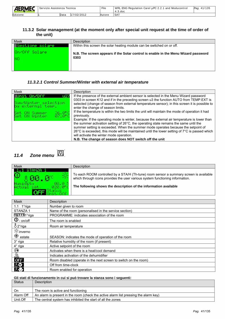
Servizio Assistenza Tecnica File WRL ENG Regulation Carel µPC 2.2.1 and Moducontrol
4.3.doc Pag. 41/135
Edizione 1 Data 17/02/2012 Autore SAT
Pag. 41/135 Pag. 41/135
11.3.2 Solar management (at the moment only after special unit request at the time of order of the unit)
Mask Description Within this screen the solar heating module can be switched on or off. N.B. The screen appears if the Solar control is enable in the Menu Wizard password 0303
11.3.2.1 Control Summer/Winter with external air temperature Mask Description
If the presence of the external ambient sensor is selected in the Menu Wizard password 0303 in screen K12 and if in the preceding screen u3 the function AUTO from TEMP.EXT is selected (change of season from external temperature sensor); in this screen it is possible to enter the change of season limits. If the temperature is within the two limits the unit will maintain the mode of operation it had previously. Example: If the operating mode is winter, because the external air temperature is lower than the summer activation setting of 26°C, the operating state remains the same until the summer setting is exceeded. When the summer mode operates because the setpoint of 26°C is exceeded, this mode will be maintained until the lower setting of 7°C is passed which will activate the winter mode operation. N.B. The change of season does NOT switch off the unit
11.4 Zone menu Mask Description
To each ROOM controlled by a STA/H (Th-tune) room sensor a summary screen is available which through icons provides the user various system functioning information. The following shows the description of the information available
Mask Description 1.1 1°riga Number given to room STANZA 1 Name of the room (personalised in the service section)
1°riga PROGRAMME: indicates association of the room - on/off The room is enabled
2°riga Room air temperature inverno estate SEASON: indicates the mode of operation of the room
3° riga Relative humidity of the room (if present) 4° riga Active setpoint of the room
Activates when there is a heat/cool demand Indicates activation of the dehumidifier
Room disabled (operate in the next screen to switch on the room) Off from time-clock Room enabled for operation
Gli stati di funzionamento in cui si può trovare la stanza sono i seguenti: Status Description
On The room is active and functioning Alarm Off An alarm is present in the room (check the active alarm list pressing the alarm key) Unit.Off The central system has inhibited the start of all the zones

Servizio Assistenza Tecnica File WRL ENG Regulation Carel µPC 2.2.1 and Moducontrol
4.3.doc Pag. 42/135
Edizione 1 Data 17/02/2012 Autore SAT
Pag. 42/135 Pag. 42/135
Status Description Disabl. The room is not configured (check service/assistance parameters) Off Sched. The room is disabled by the time-clock (check the associated programme) DigIN Off Disabled by input to the pCOe (only with configuration Th-tune disabled) Off tasto The room is disabled by the user Mask Description
The screen indicates the temporary control setpoint that the room sensor is working to, in this screen ROOM 1 is shown. The operating setpoint limits can be modified in the Menu Service password 0101, in sub-menu Zone. The room can be switched on or off through the “Enable room” setting. P.S. If the time-clock operates this setpoint is overwritten each time the time-clock is updated
The screen indicates the time-clock to which the room is associated, in this screen ROOM 1 is shown. N.B. In the case other rooms are activated in the Menu Wizard password 0303 (if the respective pCOe expansion boards are installed) the following additional screens will appear: - r15 and r18 for ROOM 2 - r24 and r27 for ROOM 3 - r33 and r36 for ROOM 4 - r42 and r45 for ROOM 5 In this way specific setpoints in specific time-clock settings of the day can be controlled. PS: The programmes associated to the rooms are controlled from within the Menu time-clock
The screen indicates the dehumidifier setpoints of Zones 1, 2 and 3. The operating limits must be adjusted from the Menu Service in the sub-menu Zone
The screen indicates the humidifier setpoint. The operating limits must be adjusted from the Menu Service in the sub-menu Zone
The screen shows various information on the state of Zone 1: - The pump of the active zone is shown with the P circled - The water temperature of the zone - The active setpoint at that time - The active differential at that time - The state of the mixing valve 0..10 Volt - The state of the zone ( On, Alarm, Manual, Disabl., Room Off, Off Rem, Unit Off ) N.B. In the case other zones are activated the following screens will also appear always with the same indications: r57 for ZONE 2 r60 for ZONE 3
The screen indicates the chilled water Setpoint, example Zone 1 (screen r72 for Zone 2 and r78 for Zone 3). The operating limits must be adjusted from the Menu Service in the sub-menu Zone

Servizio Assistenza Tecnica File WRL ENG Regulation Carel µPC 2.2.1 and Moducontrol
4.3.doc Pag. 43/135
Edizione 1 Data 17/02/2012 Autore SAT
Pag. 43/135 Pag. 43/135
11.5 Menu Chiller Screen Description
The screen shows the system water Setpoint and demand
Icon Description
12.0°C Active system Setpoint (example 12.0°C) winter summer SEASON: indicates the operating mode of the room
Diff. 03.0°C Active control Differential (example 3°C)
Demand 100%
Load demand for compressor(s) from the thermostat (example demand 100%). In the case of a unit with only one compressor, the compressor is switched on after the 100% demand is visible in the % of the screen (and after compressor minimum stop timer). In the case of 2 compressors present, the starting and operation of the compressors will be additionally tied to the requested % demand, to the different running hours (the compressor with the least running hours will start first), and to the minimum compressor stop time
Screen Description
Unit temperature control. Adjustable hot and cold water nominal Setpoint
Unit temperature control Adjustable hot and cold water Comfort Setpoint
Index Scr.
Description display
Description Description Values Def. Unit Min Max R/W
S6 Setpoint Comfort Water setpoint in heating --- 35.0 °C Me9 Me9 RW
Water setpoint in cooling --- 17.0 °C Me9 Me9 RW S9 Setpoint Economy
The economy function can be activated from screen u3 Menu ON/OFF or the Time-clock (Menu User)
Water setpoint in heating 32.0 °C Me9 Me9 RW
Water setpoint cooling The economy function can be activated from screen u3 Menu ON/OFF or the Time-clock (Menu User)
20.0 °C Me9 Me9 RW
11.6 Menu DHW Screen Description
In this screen the operation of the DHW tank and the water temperature can be monitored

Servizio Assistenza Tecnica File WRL ENG Regulation Carel µPC 2.2.1 and Moducontrol
4.3.doc Pag. 44/135
Edizione 1 Data 17/02/2012 Autore SAT
Pag. 44/135 Pag. 44/135
Icon Description
Setpoint 50.0°C Active DHW setpoint (adjustable), example 50.0°C
Hot water demand DHW tank. The DHW pump will switch on when the bar turns completely black and will switch off when no demand is shown
Demand 94% The compressors will be switched on based on the heat recovery outlet water temperature sensor. If the demand reached 100% all compressors will be switched on
Enabled Allows the user the switch on/off the supply of DHW
3rd row If the image flashes the immersion heater is on. This can be switched on manually as supplementary or for the programmed anti-legionella cycle
The available states of the DHW are: State Description On The system is available to produce DHW Alarm A alarms is present relative to the DHW (check the active alarm list pressing the alarm key) Comp Off If the DHW is configured as desuperheater and the compressor is off then hot water cannot be produced Unit Off The central system (for example from remote ON/OFF) has inhibited the start of all devices Time-Cl Off DHW is disabled by time-clock Off key DHW is disabled by user Manual DHW is forced by digital input independent from unit switch off (by accessory pCOe expansion board) Screen Description
Select DHW time-clock
In this screen it is possible to enter the time-clock programmes. Up to 4 daily programmes can be selected (a, b, c, d), for the 7 days of the week
Entering this screen the time-clock programmes for one day of the week can be copied for all the other days
11.6.1.1 Anti-legionella Treatment The Legionella bacteria are very dangerous and proliferate in DHW tanks. As can be seen from the image below above a certain temperature the bacteria can instantly be killed. The anti-legionella procedure can be enabled from the Menu DHW screen D18 of the Menu User.
This function is only available if the immersion heater or supplementary system heater within the DHW tank is enabled (see Menu Wizard password 0303 screen K21). Attention: the unit must also be configured as total heat recovery or without heat recovery (digit T or ° in the Menu set-up procedure password 0009), entering in the Menu Wizard password 0303, TOTAL HEAT RECOVERY. (Automatic if the WRL unit is configured with digit T in the Menu set-up procedure password 0009) or PRIORY+ VALVE or PRIORITY+PUMP.
This function raises the temperature within the DHW tank for a determined time. The specific parameters are found in the Menu Service password 0101 entering the sub-menu DHW, screen Q15.

Servizio Assistenza Tecnica File WRL ENG Regulation Carel µPC 2.2.1 and Moducontrol
4.3.doc Pag. 45/135
Edizione 1 Data 17/02/2012 Autore SAT
Pag. 45/135 Pag. 45/135
User side 2nd line: indicate that is the anti-legionella function activation hour 3rd line: indicate the days of the week enabled 4th line: indicate the enabling of anti-legionella function NB: This function is active even with the unit OFF.
Index Scr.
Description display
Description Description Values
Def. Unit Min Max R/W
Q15 Anti-legionella
Function start hour 3.00 h 0 23 RW
Mon, Tue,…… Sun.
Day which the cycle starts Mo RW
Enable Enabling of the function 0 1 RW
11.7 Menu Clock Screen Description
In the first screen of this menu the system time can be changed. To commence the change of hour pressing the ENTER key is sufficient; on first pressing the numbers showing the hour are displayed. To modify the value use the (UP) and (Down) keys. To confirm the selection of the hour press the enter key then passing to the modification of the minutes. The change of system time is completed with the modification of the seconds and confirmation by pressing the key
In this screen the automatic change between Winter and Summer time is possible
Index Scr.
Description display
Description Description Values Def. Unit Min Max R/W
C3 Day of the week Day of the week based on the date
MONDAY TUESDAY WEDNESDAY THURSDAY FRIDAY SATURDAY SUNDAY
-- -- 1 7 R
Date Enter Day (dd),Month (mm), Year (yy)
---- -- -- 0 0 0
31 12 99
RW
Time Enter hour and minutes --- 0 0 0
23 59
RW
C6 Summer time Enable Summer time 0. NO 1. YES
No --- 0 1 RW
Trans time Variation relative Winter time -- 0 min -90 90 RW Init. Day/time start Summer time FIRST
SUNDAY/SATURDAY LAST SUNDAY/SATURDAY
-- RW
End Day/time finish Summer time FIRST SUNDAY/SATURDAY LAST SUNDAY/SATURDAY
RW

Servizio Assistenza Tecnica File WRL ENG Regulation Carel µPC 2.2.1 and Moducontrol
4.3.doc Pag. 46/135
Edizione 1 Data 17/02/2012 Autore SAT
Pag. 46/135 Pag. 46/135
11.8 Time zones menu
The application has 5 programmes (scenarios) present that can be associated to the various rooms. Each programme has 8 possibilities, 7 days plus 1 holiday, each day has four time-clock programmes to enable the hour to switch on and switch off, setpoint summer and winter. Outside of these 4 time-clock programmes the relevant room is switched. The change of the time-clock overwrites the temporary setpoint. Screen Description
In this screen one of the 5 programmes relative to the Menu time-clock can be selected (example Programme 3). Pressing the Enter key enters the relative programme
Programme 3 = name of the programme (example Programme 3) Day MONDAY = selection day of the week (example MONDAY) The possible selections are: from MONDAY to SUNDAY a = ON and OFF of the first time-clock programme b = ON and OFF of the second time-clock programme
Programme 3 = name of the programme (example Programme 3) Day MONDAY = selection day of the week (example MONDAY) The possible selections are: from MONDAY to SUNDAY c = ON and OFF of the third time-clock programme d = ON and OFF of the fourth time-clock programme
In this screen all the days of the week can be entered with the same selections made for the day chosen. The possible selections are: MONDAY…SUNDAY or ALL
IMPORTANT: From software version 2.3.0 it is possible to directly access the Assistance sub-menu of the Menu User simply by pressing the key. The access method to the Menu User sub-menus and to the Menus Wizard (password 0303), Set-up procedure (password 0009), Assistance (password 0101) and Manufacturer (password 0202) remain as described in the screens of pages 26 and 27.
Set B Set C Set D Set A
a-On a-Off b-On b-Off c-On c-Off d-On d-Off 00:00 24:00

Servizio Assistenza Tecnica File WRL ENG Regulation Carel µPC 2.2.1 and Moducontrol
4.3.doc Pag. 47/135
Edizione 1 Data 17/02/2012 Autore SAT
Pag. 47/135 Pag. 47/135
12 Menu Service (password 0101) From the Menu User, pressing the Enter key on the symbol enters the Menu Service. To access the Menu Service enter the password 0101 in the access screen.
The group of screens of the Menu Service are password protected. On the first screen the password is requested. Screen Description
Press the Prog key and enter the Menu Service (see dedicated section) then press Enter and insert the password 0101 The password is always fixed at 0101 The password displayed will return to 0 after 5 minutes of inactivity of the user terminal.
Procedure to enter Menu Service (password 0101): press the key to move to screen continue to press to arrive at the screen
0101
sotto-menu
sub-menu
SERVICE Menu

Servizio Assistenza Tecnica File WRL ENG Regulation Carel µPC 2.2.1 and Moducontrol
4.3.doc Pag. 48/135
Edizione 1 Data 17/02/2012 Autore SAT
Pag. 48/135 Pag. 48/135
Icon Text Description
1) LANGUAGE Select language, enable visualisation change of language after re-start of board
2) INFO Software version
3) ZONE Temperature control differential, name of room, default setpoint, type of valve control, type of humidifier, setpoint limits
4) CHILLER Differential, type of control, geothermal parameters, electronic expansion valve EEV setpoint
5) SANITARY Setpoint limits, DHW differential, type of control, DHW immersion heater, anti-legionella.
6) PUMPS Type of control, start/stop delay, geothermal parameters
7) SOLAR Parameter for control of the solar supplementary heating
8) HOUR COUNTER
Device hours run, limits hours run, setting hours run alarm
9) MANUAL Forced pump, forced electronic expansion valve, forced anti-legionella procedure
10) OPTIONAL Enable freecooling, solar kit, supplementary immersion heater/boiler, enable solar module. BMS
configuration
11) PLANT CONF.
Type of chiller, type of DHW, number of compressors, number of zones, enable sensors and digital inputs
12) USER Cancel alarm history, personalise password, unit of measurement
13) IN/OUT Detailed status of all inputs and outputs
Once in the Menu Service it is possible to run though the list of sub-menus using the keys + The chosen sub-menu is selected pressing the key. To modify the parameter(s) or content(s) of the sub-menu use the key and to modify the parameter(s) use the and keys. To confirm the required modification press the key.
The appearance of many screens contained in the sub-menus detailed below is directly linked to the selections in the Menu Wizard (password 0303) and Menu set-up procedure (password 0009). In reference to the selections in these Menus (Menu Wizard and Menu set-up procedure), many screens in the sub-menu of the Menu Service appear already configured. Some screens contained in the sub-menus detailed here are only visible after enabling options contained in other screens of the same sub-menu (for example Zones) or other options contained in sub-menus of the Menu Service.
12.1 Language Mask Index
Display view Description Values Def. UOM Min Max R/W
Ga01 Change lang. Language Change from Italian language to
English, German or French It is possible select it during the first start-up or after into this mask
0. ENGLISH 1. ITALIANO 2.DEUTSCH 3.FRANCAIS
--- --- 0 3 RW

Servizio Assistenza Tecnica File WRL ENG Regulation Carel µPC 2.2.1 and Moducontrol
4.3.doc Pag. 49/135
Edizione 1 Data 17/02/2012 Autore SAT
Pag. 49/135 Pag. 49/135
Mask Index
Display view Description Values Def. UOM Min Max R/W
Ga02 Change lang. Enable selection mask Start-up lang.
Disable the language change screen at start-up
0. NO 1. YES
0 --- 0 1 RW
Display time Time that the language change screen is on at start-up
30 s 0 999 RW
12.2 Info Mask Index
Display view Description Values Def. UOM Min Max R/W
Gb01 Aermec WRL160XH°°IPQ° (example)
Unit configuration See the Menu Set Up Procedure Password 0009
--- --- --- --- R
Ver 2.2.1 26/10/11 Software version 04/11/11 (example)
Test factory date It isn’t the factory realization of the unit
--- --- --- --- R
12.3 Zone Mask Index
Display view Description Values Def. UOM Min Max R/W
Z3 Zone Differential for activation request of the room
--- 2,0 °C -99.9 99.9 RW
Z6 1.1 STANZA 1 Room name Customer room name STANZA 1 (example)
A…Z e da 0..9 e “+” “-“ STANZA 1
--- 0 38 RW
Z9 2.1 STANZA 2 Room name Customer room name STANZA 2 (example)
A…Z e da 0..9 e “+” “-“ STANZA 2
--- 0 38 RW
Z12 2.2 STANZ 3 Room name Customer room name STANZA 3 (example)
A…Z e da 0..9 e “+” “-“ STANZA 3
--- 0 38 RW
Z15 3.1 STANZA 4 Room name Customer room name STANZA 4 (example)
A…Z e da 0..9 e “+” “-“ STANZA 4
--- 0 38 RW
Z18 3.2 STANZA 5 Room name Customer room name STANZA 5 (example)
A…Z e da 0..9 e “+” “-“ STANZA 5
--- 0 38 RW
Z21 1.1 STANZA 1 Set point default
22.0°C 20.0°C
Initial setpoint, to be used when changing season and if time periods have been enabled but do not operate
22.0 20.0
°C 16.0 06.0
30.0 30.0
RW
Z24 2.1 STANZA 2 Set point default
22.0°C 20.0°C
Initial setpoint, to be used when changing season and if time periods have been enabled but do not operate
22.0 20.0
°C 16.0 06.0
30.0 30.0
RW

Servizio Assistenza Tecnica File WRL ENG Regulation Carel µPC 2.2.1 and Moducontrol
4.3.doc Pag. 50/135
Edizione 1 Data 17/02/2012 Autore SAT
Pag. 50/135 Pag. 50/135
Mask Index
Display view Description Values Def. UOM Min Max R/W
Z27 2.2 STANZA 3 Set point default
22.0°C 20.0°C
Initial setpoint, to be used when changing season and if time periods have been enabled but do not operate
22.0 20.0
°C 16.0 06.0
30.0 30.0
RW
Z30 3.1 STANZA 4 Set point default
22.0°C 20.0°C
Initial setpoint, to be used when changing season and if time periods have been enabled but do not operate
22.0 20.0
°C 16.0 06.0
30.0 30.0
RW
Z33 3.2 STANZA 5 Set point default
22.0°C 20.0°C
Initial setpoint, to be used when changing season and if time periods have been enabled but do not operate
22.0 20.0
°C 16.0 06.0
30.0 30.0
RW
Z36 Zone Valve 1 Cold regulation Summer adjustment of the Y3
mixing valve from Carel µPC electronic board directly
0.FIXED SETPOINT 1. CLIMATIC CURVE 2. DEW POINT
0 --- 0 2 RW
Heat regulation Winter adjustment of the Y3 mixing valve from Carel µPC
0.FIXED SETPOINT 1.TEMP. CURVE
0 --- 0 1 RW
Z39 Zone (this mask is visible if is enable the TEMP.CURVE on the Heat regulation into Mask Z36 into this menu) Valve 1 WIN Winter management Deliv. Set Current setpoint of water delivery --- °C -99.9 99.9 R
Set by 3 external air temperature (Y axis) and 3 delivery water temperature (X axis) values to generate the winter climate curve desired
Exthernal air temperature (Y axis)
20.0 15.0 0.0
°C -99.9 99.9 RW
Delivery water temperature (X axis)
35.0 30.0 28.0
°C -99.9 99.9 RW
Z42 Zone (this mask is visible if is enable the CLIMATIC CURVE on the Cold regulation into Mask Z36 into this menu) Valve 1 EST Summer management Del. Set Current setpoint of water delivery --- °C -99.9 99.9 R
Set by 3 external air temperature (Y axis) and 3 delivery water temperature (X axis) values to generate the winter climate curve desired
Exthernal air temperature (Y axis)
22.0 16.0 15.0
°C -99.9 99.9 RW
Delivery water temperature (X axis)
18.0 16.0 35.0
°C -99.9 99.9 RW
Z45 Zone (this mask is visible if is enable the DEW POINT on the Cold regulation into Mask Z36 into this menu) Valve 1 EST Summer management Anti-condens. Funct. Offset temperature mixed circuit in sum. mode
1.5 °C -99.9 99.9 RW
Setp. active Actual setpoint --- °C -99.9 99.9 R Z48 Zone
Valve 2 Cold regulation Summer adjustment of the mixing
valve output Y1 of expansion boad pCOe zone 2
0.FIXED SETPOINT 1. CLIMATIC CURVE 2. DEW POINT
0 --- 0 2 RW
Heat regulation Winter adjustment of the mixing valve output Y1 of expansion boad pCOe zone 2
0.FIXED SETPOINT 1.TEMP. CURVE
0 --- 0 1 RW
Z51 Zone (this mask is visible if is enable the TEMP.CURVE on the Heat regulation into Mask Z48 into this menu) Valve 2 WIN Winter management Deliv. Set Current setpoint of water delivery --- °C -99.9 99.9 R
Set by 3 external air temperature (Y axis) and 3 delivery water temperature (X axis) values to generate the winter climate curve desired
Exthernal air temperature (Y axis)
20.0 15.0 0.0
°C -99.9 99.9 RW
Delivery water temperature (X axis)
35.0 30.0 28.0
°C -99.9 99.9 RW

Servizio Assistenza Tecnica File WRL ENG Regulation Carel µPC 2.2.1 and Moducontrol
4.3.doc Pag. 51/135
Edizione 1 Data 17/02/2012 Autore SAT
Pag. 51/135 Pag. 51/135
Mask Index
Display view Description Values Def. UOM Min Max R/W
Z54 Zone (this mask is visible if is enable the CLIMATIC CURVE on the Cold regulation into Mask Z48 into this menu) Valve 2 EST Summer management Del. Set Current setpoint of water delivery --- °C -99.9 99.9 R
Set by 3 external air temperature (Y axis) and 3 delivery water temperature (X axis) values to generate the winter climate curve desired
Exthernal air temperature (Y axis)
22.0 16.0 15.0
°C -99.9 99.9 RW
Delivery water temperature (X axis)
18.0 16.0 35.0
°C -99.9 99.9 RW
Z57 Zone (this mask is visible if is enable the DEW POINT on the Cold regulation into Mask Z48 into this menu) Valve 2 EST Summer management Anti-condens. Funct. Offset temperature mixed circuit in sum. mode
1.5 °C -99.9 99.9 RW
Setp. active Actual setpoint --- °C -99.9 99.9 R Z60 Zone
Valve 3 Cold regulation Summer adjustment of the mixing
valve output Y1 of expansion boad pCOe zone 3
0.FIXED SETPOINT 1. CLIMATIC CURVE 2. DEW POINT
0 --- 0 2 RW
Heat regulation Winter adjustment of the mixing valve output Y1 of expansion boad pCOe zone 3
0.FIXED SETPOINT 1.TEMP. CURVE
0 --- 0 1 RW
Z63 Zone (this mask is visible if is enable the TEMP.CURVE on the Heat regulation into Mask Z60 into this menu) Valve 3 WIN Winter management Deliv. Set Current setpoint of water delivery --- °C -99.9 99.9 R
Set by 3 external air temperature (Y axis) and 3 delivery water temperature (X axis) values to generate the winter climate curve desired
Exthernal air temperature (Y axis)
20.0 15.0 0.0
°C -99.9 99.9 RW
Delivery water temperature (X axis)
35.0 30.0 28.0
°C -99.9 99.9 RW
Z66 Zone (this mask is visible if is enable the CLIMATIC CURVE on the Cold regulation into Mask Z60 into this menu) Valve 3 EST Summer management Del. Set Current setpoint of water delivery --- °C -99.9 99.9 R
Set by 3 external air temperature (Y axis) and 3 delivery water temperature (X axis) values to generate the winter climate curve desired
Exthernal air temperature (Y axis)
22.0 16.0 15.0
°C -99.9 99.9 RW
Delivery water temperature (X axis)
18.0 16.0 35.0
°C -99.9 99.9 RW
Z69 Zone (this mask is visible if is enable the DEW POINT on the Cold regulation into Mask Z60 into this menu) Valve 3 EST Summer management Anti-condens. Funct. Offset temperature mixed circuit in sum. mode
1.5 °C -99.9 99.9 RW
Setp. active Actual setpoint --- °C -99.9 99.9 R Z72 Zone
Plant system Plant 3-way valve Proportional or integral
adjustment of water valve
0. P (proportional) 1. P+I (proportional + integral)
1 --- 0 1 RW
Prop. band Valve differential value 4.0 °C 0.5 15.0 Rw Integ. time Valve integral adjustment time 600 s 0 999 RW Valve logic Valve rotation verse 0..10Volt 0.DIRECT: 0..10Volt
1.INVERSE: 10..0 Volt 0 --- 0 1 RW

Servizio Assistenza Tecnica File WRL ENG Regulation Carel µPC 2.2.1 and Moducontrol
4.3.doc Pag. 52/135
Edizione 1 Data 17/02/2012 Autore SAT
Pag. 52/135 Pag. 52/135
Mask Index
Display view Description Values Def. UOM Min Max R/W
Z75 Zone Humidifier type Enable humidifier 0. NOT PRESENT
1. MODULAT. 0 --- 0 1 RW
Dehumifier type Enable dehumidifier On/Off zone 1, zone 2, zone 3, refer on the Menu wizard password 0303
0. NOT PRESENT 1. ON/OFF
0 --- 0 1 RW
Z78 Zone (this mask is visible if is enable the Dehumifier type ON/OFF into the precedent mask) Zone system Dif. dehumidification: Dehumidifier differential working
value 5,0 %rH 0.0 99.9 RW
Humidification band: Humidifier working band 5,0 %rH 0.0 99.9 RW
Z81 Zone Rooms Temperature set limits Summer min Room temperature min. setpoint
in winter mode 16.0 °C -99.9 99.9 RW
Summer max Room temperature max. setpoint in summer mode
30.0 °C -99.9 99.9 RW
Winter min Room temperature min. setpoint in winter mode
6.0 °C -99.9 99.9 RW
Winter max Room temperature max. setpoint in winter mode
30.0 °C -99.9 99.9 RW
12.4 Chiller Mask Index
Display view Description Values Def. UOM Min Max R/W
E3 Chiller Setpoint plant System compr. Reg. type Proportional or integral regulation
adjustment of the compressors
0. P (proportional) 1. P+I (proportional + integral)
0 --- 0 1 RW
Pr. Band sys. Compressor differential activation value from plant request
5.0 0.5 15.0 Rw
Integral time Compressor adjustment integral time
600 s 0 999 RW
E4 Chiller Compressors off with Zones off
When no zones demand compressor can be stopped
0.NO 0.YES
0 --- 0 1 RW
Delay off Delay to stop compressor when no zones demand
30 min 0 999 RW
Delay On Delay to start compressor when there is zones demand
2 min 0 999 RW
E6 Chiller Setpoint plant Cold regulation Summer adjustment setpoint type 0. FIXED SETPOINT
1. TEMP. CURVE 0 --- 0 1 RW
Heat regulation Winter adjustment setpoint type 0. FIXED SETPOINT 1. TEMP. CURVE
0 --- 0 1 RW
E9 Chiller (this mask is visible if is enable the TEMP.CURVE on the Heat regulation into the E6 mask) Setpoint plant WIN Actual Set: Current setpoint value --- °C --- --- R Min.T.Ext Min. ext. temperature 0.0 °C -99.9 99.9 RW Max.T.Ext Max. external temperature 10.0 °C -99.9 99.9 RW Max Offset Max. deviation of the “comfort” or
“economy” chiller setpoint -1.0 °C -99.9 99.9 RW

Servizio Assistenza Tecnica File WRL ENG Regulation Carel µPC 2.2.1 and Moducontrol
4.3.doc Pag. 53/135
Edizione 1 Data 17/02/2012 Autore SAT
Pag. 53/135 Pag. 53/135
Mask Index
Display view Description Values Def. UOM Min Max R/W
E12 Chiller (this mask is visible if is enable the TEMP.CURVE on the Cold regulation) Setpoint plant EST Actual Set: Current setpoint value --- °C --- --- R Min.T.Ext Min. ext. temperature 25.0 °C -99.9 99.9 RW Max.T.Ext Max. external temperature 30.0 °C -99.9 99.9 RW Max Offset Max. deviation of the “comfort” or
“economy” chiller setpoint 1.5 °C -99.9 99.9 RW
E18 Chiller Force off compressors. by low temperature Delivery temp.plant
Forced to off compressors without minimum compressor start timing
Diff. over antifreezer Differential to add up on the antifreeze limit
1.0 °C 0 10.0 RW
Actual limit Actual limit calculate --- °C --- --- R E21 Chiller
Low charge Enable function 0. YES
1. NO 0 --- 0 1 RW
Min. operating time Alarm control delay after compressor start
600 s 0 999 RW
Differential Min. differential value between evaporator inlet and outlet temperature
2.0 °C -99.9 99.9 RW
E24 Chiller Auto. definiction of the differential
0. NO 1. YES
0 0 1 RW
Time startup unit 3 min 0 999 RW Min. Diff. 3.0 °C -99.9 99.9 RW Max. Diff. 8.0 °C -99.9 99.9 RW
E27 Chiller (this mask is visible if is enable YES on Auto. definiction of the differential into the precedent mask) Automat.definict.diff. Chiller 5.0 °C 0 8.0 RW HeatPump 5.0 °C 0 8.0 RW
12.5 Sanitary Mask Index
Display view Description Values Def. UOM Min Max R/W
Q6 Sanitary water Sanitary compr. reg. type Proportional or integral
adjustment of the thermostat to produce sanitary water
0. P (proportional) 1. P+I (proportional + integral)
0 --- 0 1 RW
San. Prop. Band Sanitary hot water differential value
4.0 °C 0.5 15.0 RW
Integral time Compressor adjustment integral time to produce sanitary water
600 s 0 999 RW
Q12 Sanitary water Waiting time for inversion of san. valve
The software waits for this time when priority shifts from system water production to sanitary water
Only visible with total recovery+mixing and sanitary valve enable: PRIORITARY+VALV. See Menu Wizard K6 mask Sanitary type
90 s 0 999 RW

Servizio Assistenza Tecnica File WRL ENG Regulation Carel µPC 2.2.1 and Moducontrol
4.3.doc Pag. 54/135
Edizione 1 Data 17/02/2012 Autore SAT
Pag. 54/135 Pag. 54/135
Mask Index
Display view Description Values Def. UOM Min Max R/W
Q15 Sanitary water (this mask is visible if is select TOTAL RECOVERY T letter into Menu Set Up Procedure password 0009 or if is select SANITARY presence into K6 mask and after insert HEATING EL. presence into K21 mask on Menu Wizard password 0303) Antilegionella End setpoint Max. limit beyond which the
antilegionella treatment ends 65.0 °C 0.0 99.9 RW
Minimum time Min. time spent above the setpoint to complete the function
5 min 0.0 999 RW
Maximum time Max. time spent above the setpoint to complete the function
120 min 0.0 500 RW
Q21 Sanitary water HP termoregolation Enable high pressure control with
inverter pump or modulating valve
0 NO 1 YES
0 0 1
Setpoint 18.0 bar 0 50.0 RW Differential 2.0 bar 0 50.0 RW Min. speed Minimum percentage speed
(inverter pump) / open (modulating valve)
10.0 % 0 100 RW
Max. speed Maximum percentage speed (inverter pump) / open (modulating valve)
100.0 % 0 100 RW
Q24 Sanitary water Delay time between Compressor ON and sanitary
Time delay between ON compressor/s and ON sanitary pump
--- 30 s 0 900 RW
Q27 Sanitary water Delay time betw. Off sanitary pump and Off compressors
Time delay between OFF sanitary pump from OFF compressor/s
--- 10 s 0 900 RW
Q30 Sanitary water Regolat. Outlet water Indicate the probe where the
system working to produce the sanitary water. The probes may be: - Buffer tank probe - Outlet water probe - Inlet water probe - Total rcovery outlet water probe
Setpoint 57.0 °C 0.0 99.9 RW Differential 3.0 °C 0.0 99.9 RW
12.6 Pumps Mask Index
Display view Description Values Def. UOM Min Max R/W
P3 Pumps System control Primary circuit pump active
Activates primary circuit pump 0: UNIT ON 1: ON REQUIRE COMP.
0 --- 0 1 RW
P6 Pumps Delay time between Compressor ON and plant pump
Compressor On delay time after plant pump On
--- 60 s 0 900 RW
P9 Pumps Delay time betw. Off plant pump and Off compressors
Plant pump off delay time after compressor off
--- 30 s 0 900 RW
P12 Pumps Delay time between Compressor On and geoth. pump On
Compressor On delay time after geothermal pump On
--- 60 s 0 999 RW

Servizio Assistenza Tecnica File WRL ENG Regulation Carel µPC 2.2.1 and Moducontrol
4.3.doc Pag. 55/135
Edizione 1 Data 17/02/2012 Autore SAT
Pag. 55/135 Pag. 55/135
Mask Index
Display view Description Values Def. UOM Min Max R/W
P15 Pumps Delay time betw. Off geoth. pump and Off compressors
Geothermal pump Off delay after compressor Off
--- 30 s 0 999 RW
P18 Pumps (this mask is visible if is select Desuperheater D letter into Menu Set Up Procedure password 0009) Sanitary circuit Sel. Sanitary pump in summer
If a desuperheater is present, the sanitary probe can be ignored and the pump can always be On
0: ON COMPRESSOR 1: ON REQUIRE
1 --- 0 1 RW
P21 Pumps Pump regulation geothermal side
The geothermal pump can be in On in reference to the solutions present into the near table
0: MACHINE ON 1: WITH THE COMP. ON 2: WITH COMP.ON + INVERTER 3: WITH COMP.ON + VALV
1 --- 0 3 RW
Regulat. Inverter/valv The inverter pump or the modulating valve can be operate in reference the solutions present into the near table
0. TEMPERATURE OUTLET GEO 1. TEMPERATURE INLET GEO 2. HIGH PRESSURE
2 --- 0 2 RW
P24 Pumps (this mask is visible if is select HIGH PRESSURE into Regulat. Inverter/valv, parameter P21) Geo pump (summer) Setpoint Summer setpoint of modulating
geothermal pump 17.0 bar 0 99.9 RW
Differential Adjustment point, central setpoint 12.0 bar 0 99.9 RW Geo pump (winter) Speed (1° comp) A fixed speed is set in winter 80.0 % 0.0 100.0 RW Speed (2° comp) 80.0 % 0.0 100.0 RW
P27 Pumps (this mask is visible if is select TEMPERATURE INLET/OUTLET GEO. into Regulat. Inverter/valv, parameter P21) Plant control Geo pump setpoint Summer Summer/Winter setpoint of
modulating geothermal pump 35 °C 0 99.9 RW
Winter 6.5 °C 0 99.9 RW P30 Pumps (this mask is visible if is select TEMPERATURE INLET/OUTLET GEO. into Regulat. Inverter/valv, parameter P21)
Plant system Geo pump band Summer Temperature band about
regulation of modulating geothermal pump, Summer/Winter
10.0 °C 0 99.9 RW Winter 10.0 °C 0 99.9 RW
P33 Pumps (this mask is visible if is select Total Recovery T letter, into Menu Set Up Procedure password 0009) Geo pump Recovery setpoint Summer
Summer setpoint of modulating geothermal pump for total recovery
25.0 bar 0 99.9 RW
Band 10.0 bar 0 99.9 RW P34 Pumps(this mask is visible if is select Total Recovery T letter, into Menu Set Up Procedure password 0009)
Total recovery Force condenser pump During the DHW sanitary water or
plant working to produce hot water, with this function is possible recover the heat energy from the condenser exchanger in off (sanitary exchanger or plant exchanger) with turn on the water pump of this, in case the suction pressure go down below the set-point setted below.
In some case is necessary unable this function (0:NO) (in any case ask in factory)
0: NOT CONF. 1: BY PASS VALV 2: ALWAYS 3. ONLY WINTER
0 0 3 RW
Low Threshol of evaporator
7.0 bar 0 99.9 RW
Differential 0.5 °C 0 99.9 RW Water low temp. 15.0 °C 0 99.9 RW

Servizio Assistenza Tecnica File WRL ENG Regulation Carel µPC 2.2.1 and Moducontrol
4.3.doc Pag. 56/135
Edizione 1 Data 17/02/2012 Autore SAT
Pag. 56/135 Pag. 56/135
Mask Index
Display view Description Values Def. UOM Min Max R/W
P39 Pumps System control Geo pump speed Speed limits about inverter pump or
opening about modulating valve
Maximum 100.0 % 0 99.9 RW Minimum 35.0 % 0 99.9 RW
12.7 Solar Mask Index
Descrizione display
Descrizione Descrizione Valori
Def. UOM Min Max R/W
L6 Parameters Diff. between Collector temp.% e plant/sanit temp.
2.0 °C 0.0 99.9 RW
Band 20.0 °C 0.0 99.9 RW Integral t. 120 s 0.0 99.9 RW
L12 Probe calibration Lettura Offs. Plant 0.0 °C 0.0 99.9 RW Sanitary 0.0 °C 0.0 99.9 RW Collector 0.0 °C 0.0 99.9 RW
L15 Collective alarms Threshold °1: 80.0 °C 0.0 99.9 RW Threshold °2: 90.0 °C 0.0 99.9 RW Threshold °3: 100.0 °C 0.0 99.9 RW Differential: 00.0 °C 0.0 99.9 RW
L18 Alarms Maximum temperatures Max. sanitary temperature
85.0 °C 0.0 99.9 RW
Max. plant temperature 75.0 °C 0.0 99.9 RW Differential 2.0 °C 0.0 99.9 RW
L21 Collector pump Min. speed 15.0 % 0 100 RW Speed in antifreeze mode
50.0 % 0 100 RW
L24 Antifreeze
Enable function 0.NO 1.YES
0 -- 0 1 RW
Set antifreeze 1.5 °C 0.0 99.9 RW Differential 2.0 °C 0.0 99.9 RW
L27 Probes
Sanitary storage temperature
0.NOT AVAILABLE 1.INTERNAL 2.FROM BMS
2 --- 0 2 RW
Plant storage temperature
0.NOT AVAILABLE 1.INTERNAL 2.FROM BMS
2 --- 0 2 RW
Collector temperature 0.NTC 1.PT1000
1 --- 0 1 RW
L30 Conf. I/O ID01:Collector pump 1 alarm
Si --- 0 1 RW
ID02:Collector pump 2 alarm
Si --- 0 1 RW

Servizio Assistenza Tecnica File WRL ENG Regulation Carel µPC 2.2.1 and Moducontrol
4.3.doc Pag. 57/135
Edizione 1 Data 17/02/2012 Autore SAT
Pag. 57/135 Pag. 57/135
12.8 Hour counter Mask Index
Display view Description Values Def. UOM Min Max R/W
W3 Hour m. Compressor 1 Compressor/s and pumps working
hours indicate --- 000.000 h 0 999.999 R
Compressor 2 --- 000.000 h 0 999.999 R Geotherm. pump --- 000.000 h 0 999.999 R Plant pump --- 000.000 h 0 999.999 R
W6 Hour m. Sanit. pump Pump working hours indicate --- 000.000 h 0 999.999 R Zone 1 pump --- 000.000 h 0 999.999 R Zone 2 pump --- 000.000 h 0 999.999 R Zone 3 pump --- 000.000 h 0 999.999 R
W12 Hour m. setting Comp thresholds (h) Compressors Compressor/s hour counter
threshold --- 099.000 h 0 999.999 RW
Pumps Pumps hour counter threshold --- 099.000 h 0 999.999 RW W15 Hour m. setting
Hour m. reset Compressor 1 Reset hour counter compressors
and pumps indicate 0. NO 1. YES
0 --- 0 1 RW Compressor 2 0 --- 0 1 RW Geothermal pump 0 --- 0 1 RW Plant pump 0 --- 0 1 RW
W18 Hour m. setting Hour m. res. Pompa sanitario Reset hour counter pumps indicate 0. NO
1. YES 0 --- 0 1 RW
Mixed pump 1 0 --- 0 1 RW Mixed pump 2 0 --- 0 1 RW Mixed pump 3 0 --- 0 1 RW
12.9 Manual Mask Index
Display view Description Values Def. UOM Min Max R/W
M3 Manual manag. NO2 Geo pump Manual start of geothermal plant
pump 0. AUT 1.MAN (forced ON)
0 --- 0 1 RW
NO3 Plant pump Manual start of plant pump 0. AUT 1.MAN (forced ON)
0 --- 0 1 RW
NO4 Sanitary pump Manual start of ACS pump 0. AUT 1.MAN (forced ON)
0 --- 0 1 RW
M6 Manual manag. Manual valve position Y3 Zone 1: Forced open Mix valve zones in
percentage measure --- 0 % 0 100 RW
Y1 Zone 2: --- 0 % 0 100 RW Y1 Zone 3: --- 0 % 0 100 RW
M27 Manual manag. (this mask is visible if is select TOTAL RECOVERY T letter into Menu Set Up Procedure password 0009 or if is select SANITARY presence into K6 mask and after insert HEATING EL. presence into K21 mask on Menu Wizard password 0303) Manual function force antilegionella
Forced of antilegionella procedure 0. AUT 1. MAN (forced ON)
0 --- 0 1 RW

Servizio Assistenza Tecnica File WRL ENG Regulation Carel µPC 2.2.1 and Moducontrol
4.3.doc Pag. 58/135
Edizione 1 Data 17/02/2012 Autore SAT
Pag. 58/135 Pag. 58/135
12.10 Optional Mask Index
Display view Description Values Def. UOM Min Max R/W
B3 Options Enable freecooling Enables GEO freecooling 0.NO
1.YES 0 --- 0 1 RW
Enable solar module Enables Solar panel 0 --- 0 1 RW B6 Options
System integration Type Select the type of plant integration 0. NONE
1. HEATING EL. 2. BOILER
0 --- 0 2 RW
Required by Select the type of support to WRL unit during plant working
0: Hp INTEGRATION 1: Hp REPLACEMENT
0 --- 0 1 RW
B9 Options Sanitary integration Type Select the type of DHW sanitary
water integration 0. NONE 1. HEATING EL. 2. BOILER
0 --- 0 2 RW
Required by Select the type of support to WRL unit during DHW sanitary working
0: Hp INTEGRATION 1: Hp REPLACEMENT
0 --- 0 1 RW
B12 Options (this mask is visible if is select BOILER into B6 mask) Boiler enabling Based on Activation setpoint of the boiler –
external air or geo return 0: T. EXT. AIR 1: T. GEOTHER RETURN
0 --- 0 1 RW
Boiler activation delay Boiler activation delay 5 min 0 999 RW B15 Options (this mask is visible if is select BOILER into B6 and B9 masks)
Boiler setting Setpoint att. Activation setpoint (for plant) of the
boiler – external air or geo return 5.0 °C -99.9 99.9 RW
Differential Boiler activation differential value 3.0 °C -99.9 99.9 RW Setpoint DHW Activation setpoint (sanitary) of the
boiler - sanitary temperature
35.0
°C -99.9 99.9 RW
Diff. DHW Boiler activation differential value
5.0 °C -99.9 99.9 RW
B18 Options (this mask is visible if is select HEATIN EL. into B6 and B9 masks) Heaters setting Syst.diff.on Differential from the working
setpoint, to activate the plant integration resistances
8.0 °C -99.9 99.9 RW
Syst.diff.off Differential from the working setpoint, to deactivate the plant integration resistances
5.0 °C -99.9 99.9 RW
DHW diff.on Differential from the working setpoint, to activate the sanitary water integration resistances
10.0
°C -99.9 99.9 RW
DHW diff.off Differential from the working setpoint, to deactivate the sanitary water integration resistances
5.0 °C -99.9 99.9 RW
Delay On Plant resistance activation delay 300 s 0 999 RW

Servizio Assistenza Tecnica File WRL ENG Regulation Carel µPC 2.2.1 and Moducontrol
4.3.doc Pag. 59/135
Edizione 1 Data 17/02/2012 Autore SAT
Pag. 59/135 Pag. 59/135
Mask Index
Display view Description Values Def. UOM Min Max R/W
B21 Options (this mask is visible if is insert FREECOOLING into B3 mask) Freecooling Min.Delta temperature Plant-Geo sensor 5.0 °C -99.9 99.9 RW hyst. 4.0 °C -99.9 99.9 RW Pulse time freecool. check
30.0 s 0 999 RW
Time max funct. 60 min 0 999 RW B22 Options
pCOe Options Digital input 1.General alarm 0. NO
1. YES 0 --- 0 1 RW
2.Sel. Summer/Win. 0. NO 1. YES
0 --- 0 1 RW
3.Sel Comfort/Eco 0. NO 1. YES
0 --- 0 1 RW
4.Sel.Prior.Sanit. 0. NO 1. YES
0 --- 0 1 RW
B24 Config. BMS Force BMS On/off and Season
Enables the function to switch on and off the unit and change the operation mode remotely
0.NO 1.YES If is enable the VMF system, this value is forced to 1
0 --- 0 1 RW
Prot. Communic. BMS protocol setup 0. ModBus RS485 1. CAREL RS485 2. pCOload local 3. VMF
0 --- 0 3 RW
Speed BMS speed setup 0. 1200 1. 2400 2. 4800 3. 9600 4. 19200
4 dbs 0 4 RW
Address Select address no. for BMS 200 --- 0 207 RW B27 Options
pCOe Options Enable Drycooler With the pCOe accessory is
possible have the drycooler management
0.NO 1.YES
0 --- 0 1 RW
Regolation type Type of sensor to regulate the drycooler system
0.INLET TEMP. GEO 1.OUTLET TEMP. GEO 2.TEMP.DRYCOOLER 3.INLET TEMP.PLANT
0 --- 0 3 RW
B30 Options (this mask is visible if is insert Drycooler YES into B27 mask) Enable Drycooler Setpoint 15.0 °C -99.9 99.9 RW Diff. 1.0 °C -99.9 99.9 RW Delta temp. ext. 3.0 °C -99.9 99.9 RW Min speed 10.0 % 0 99.9 RW Max speed 100 % 0 99.9 RW
B33 Options Type sensor B5 Enable B5 auxiliary sensor and
type of function to use it
0.NOT AVAILABLE 1.TEMP. OUTLET RECOVERY 2.TEMP. COMMON PLANT 3.COMPENSAT.SET (4-20mA)
In case select COMPENSAZ.SET, B5 will appear into the D03 mask into menu In/Out of Menu Service
0 --- 0 3 RW

Servizio Assistenza Tecnica File WRL ENG Regulation Carel µPC 2.2.1 and Moducontrol
4.3.doc Pag. 60/135
Edizione 1 Data 17/02/2012 Autore SAT
Pag. 60/135 Pag. 60/135
Mask Index
Display view Description Values Def. UOM Min Max R/W
B36 Options (this mask is visible if is select COMPENSAT.SET (4-20mA) into B33 mask) Sensor B5 Setpoint compensation.
Is possible modify the plant set-point from exthernal input
Summer Compensation Min 00.0°C Max 05.0°C
Min0.0Max5.0
°C -99.9 99.9 RW
Winter compensation Min 00.0°C Max 05.0°C
Min 0.0 Max 5.0
°C -99.9 99.9 RW
12.11 Plant Conf. Mask Index
Display view Description Values Def. UOM Min Max R/W
H3 Configuration Chiller type Selects whether the chiller
produces hot water only or also cold water
0. COOLING ONLY 1. COOLING/HEAT 2. HEATING ONLY
1 --- 0 2 RW
Sanitary type (3 battery)
Selects whether sanitary water storage is present and how to control it
0. NOT PRESENT 1. DESUPERHEATER (Only cooling) 2. TOTAL RECOVERY (3 exchangers) 3. PRIORITARY+VALV. (Water inversing cycle) 4. PRIORITARY+PUMP. (No Total recovery)
0 --- 1 4 RW
H6 Configuration Type Unit Reverse type It shows the type of reversing
system, if the machine is reversible
0. GAS SIDE 1. WATER SIDE
0 --- 0 1 RW
Plant pump to --- of the water valve
Selects whether the plant pump is before or after the water side cycle inversion valve
0. EXTERN. 1. INSIDE
Appear these possibilities if is insert WATER SIDE like type of inversion
0 --- 0 1 RW
H9 Configuration Number of zones radiant Number of zones the plant is
divided into --- 1 --- 0 3 RW
Number of rooms Zone 1
--- 1 --- 0 1 RW
Number of rooms Zone 2
--- 1 --- 0 2 RW
Number of rooms Zone 3
--- 1 --- 0 2 RW
H12 Configuration Type device ZONE 1 Room 1 Type of probe connected to
room 1 0. STA/H TEMP ONLY 1. STA/H T./HUM.
0 --- 0 1 RW
H15 Configuration Type device ZONE 2 Room 1 Type of probe connected to
room 1 0. STA/H TEMP ONLY 1. STA/H T./HUM.
0 --- 0 1 RW
Room 2 Type of probe connected to room 2
0. STA/H TEMP ONLY 1. STA/H T./HUM.
0 --- 0 1 RW

Servizio Assistenza Tecnica File WRL ENG Regulation Carel µPC 2.2.1 and Moducontrol
4.3.doc Pag. 61/135
Edizione 1 Data 17/02/2012 Autore SAT
Pag. 61/135 Pag. 61/135
Mask Index
Display view Description Values Def. UOM Min Max R/W
H18 Configuration Type device ZONE 3 Room 1 Type of probe connected to
room 1 0. STA/H TEMP ONLY 1. STA/H T./HUM.
0 --- 0 1 RW
Room 2 Type of probe connected to room 2
0. STA/H TEMP ONLY 1. STA/H T./HUM..
0 --- 0 1 RW
H21 Configuration Compressors number totals Select total number of
compressors 0. 1 1. 2
1 --- 0 2 RW
H24 Configuration Number max compressors active in Cooling 1 --- 0 2 RW Heating 1 --- 0 2 RW DHC 1 --- 0 2 RW
H27 Configuration Unit model Driver present of EVO electro. valve
Enables the driver of the EVO electronic valve
0. NOT PRESENT 1. PRESENT EVO ON B. 2. PRESENT EVO IN pLAN (Unit over WRL160 size)
1 --- 0 2 RW
H30 Configuration Digital inputs ID01 Geo flow switch Enables flow switch
geothermal side 0. N 1. Y
1 --- 0 1 RW
ID02 Compres.overload 1 Enables compressor 1 thermal switch
0. N 1. Y
1 --- 0 1
H33 Configuration Digital inputs ID03 High press Switch Enables circuit high pressure
pressure switch 0. N 1. Y
1 --- 0 1 RW
ID04 Pump overload/RCS Enables pump thermal switch or RCS control sequency phase
0. N 1. Y
1 --- 0 1 RW
H36 Configuration Digital inputs ID05 Humidifier Alarm Humidifier alarm input enable 0. N
1. Y 0 --- 0 1 RW
ID06 DHW Heater overl. Enables sanitary resistance thermal switch
0. N 1. Y
1 --- 0 1 RW
H39 Configuration Digital inputs ID07 Boiler alarm Enables boiler alarm
0. N 1. Y
0 --- 0 1 RW
ID08 Remote On/Off Enables remote On/Off
0. N 1. Y
1 --- 0 1 RW
H42 Configuration Digital inputs ID09 Compres. overload 2 Enable compres.2 thermal
switch
0. N 1. Y
1 --- 0 1 RW
ID10 Plant flow switch Enables plant flow switch
0. N 1. Y
1 --- 0 1 RW
H43 Configuration (this mask is visible if is able the ID08 remote On/Off contact into the mask H39) Digital inputs Remote On/Off logic Zona OFF=
On/Off input remote logic 0. CLOSE 1. OPEN
1 --- 0 1 RW
H44 Configuration Digital inputs Remote On/Off logic Zona OFF=
On/Off input remote logic 0. CLOSE 1. OPEN
1 --- 0 1 RW
H45 Configuration Digital outputs Logic inversion 4-way valve lato gas
Logic inversion 4-.way valve Heat pump cycle inversion
0. CLOSE (4 way valve activated) 1. OPEN(4 way valve not-activated)
0 --- 0 1 RW

Servizio Assistenza Tecnica File WRL ENG Regulation Carel µPC 2.2.1 and Moducontrol
4.3.doc Pag. 62/135
Edizione 1 Data 17/02/2012 Autore SAT
Pag. 62/135 Pag. 62/135
Mask Index
Display view Description Values Def. UOM Min Max R/W
H48 Configuration Digital outputs Logic inversion alarm relay Alarm relay logics 0. CLOSE
1. OPEN 1 --- 0 1 RW
H51 Configuration Sensor enable B1: Delivery Geoter. B1= Geothermal water delivery
temperature 0. N 1. Y
1 --- 0 1 RW
B2: Return Geoter. B2= Geothermal water return temperature
0. N 1. Y
1 --- 0 1 RW
B3: Sanitary Temp. B3= Sanitary water temperature 0. N 1. Y
1 --- 0 1 RW
B4: Return temp. Plant B4= Plant return water temperature
0. N 1. Y
1 --- 0 1 RW
H54 Configuration Sensor enable B5: --- B5= Auxiliary probe temperature 0. N
1. Y 0 --- 0 1 RW
B6: External temp. B6= External air temperature 0. N 1. Y
0 --- 0 1 RW
B7: Delivery plan B7= Plant water delivery temperature
0. N 1. Y
1 --- 0 1 RW
B8: Delivery zone 1 B8= Circuit mix. 1 water delivery temperature
0. N 1. Y
0 --- 0 1 RW
H57 Configuration Sensor enable B9: Delivery compr. B9= Compressor delivery
temperature 0. N 1. Y
1 --- 0 1 RW
B10: Suction compr. B10= Suction gas temperature EEV
0. N 1. Y
1 --- 0 1 RW
B11: High pressure. B11= High pressure 0. N 1. Y
1 --- 0 1 RW
B12: Low pressure B12= Low pressure 0. N 1. Y
1 --- 0 1 RW
H60 Configuration Digital inputs pCOe Zones 2, 3 ID1 Pump Overload 0. N
1. Y 1 --- 0 1 RW
ID2 Dehumid. Alarm 0. N 1. Y
1 --- 0 1 RW
ID3 Remote On/Off 0. N 1. Y
0 --- 0 1 RW
H63 Configuration (into this mas kit is possible enable or disable the probes of zones) Sensor enable pCOe Zones 2, 3 B1: Delivery water 0. N
1. Y 1 --- 0 1 RW
B2: Return water 0. N 1. Y
0 --- 0 1 RW
12.12 User Mask Index
Display view Description Values Def. UOM Min Max R/W
Hd1 Initialization New service password Insert another password --- 0101 --- 0 9999 RW

Servizio Assistenza Tecnica File WRL ENG Regulation Carel µPC 2.2.1 and Moducontrol
4.3.doc Pag. 63/135
Edizione 1 Data 17/02/2012 Autore SAT
Pag. 63/135 Pag. 63/135
Mask Index
Display view Description Values Def. UOM Min Max R/W
Hd2 Initialization Unit of measure type Select the unit of
measure 0: STANDARD (°C-barg) 1: ANGLO-SAXON (°F-psig) In case is replaced the standard unit of measure, will appear this mask to confirm
0 --- 0 1 RW
Enable change unit of meas. fr. BMS
Enables change of unit of measure from bms
0. NO 1. YES
0 --- 0 1 RW
Hd3 Initialization Enable automatic change unit of measure in masks IN/OUT
0. NO 1. YES
0 --- 0 1 RW
12.13 In/Out Mask Index
Display view Description Values Def. UOM Min Max R/W
D01 Inputs/Outputs Analogue inputs B1 =Delivery Temp. Geoth
B1= Geothermal water delivery temperature
--- --- °C -99. 9 99.9 R
B2 =Return Temp. Geoth B2= Geothermal water inlet temperature
--- --- °C -99. 9 99.9 R
D02 Inputs/Outputs Analogue inputs B3 =San. water control temp.
B3=Sanitary hot water temperature
--- --- °C -99. 9 99.9 R
D03 Inputs/Outputs Analogue inputs B4 =Return Temp. Plant B4= Primary circuit water inlet
temperature --- --- °C -99. 9 99.9 R
B5 =Comp. Set mA B5= Auxiliary probe
temperature, it is visible if is enable into the B33 mask of menu Optional with configuration COMPENSAZ. SET (4-20mA)
--- --- -99. 9 99.9 R
D04 Inputs/Outputs Analogue inputs B6 =External air temp. B6= External air temperature --- --- °C -99. 9 99.9 R B5 =Comp. Set mA B5= Auxiliary probe temperature --- --- -99. 9 99.9 R
D05 Inputs/Outputs Analogue inputs B7 =Delivery temp Plant B7= Primary system water circuit
outlet temp. --- --- °C -99. 9 99.9 R
B8 =Mix.circ.deliv 1 B8= Mix. Circuit 1 water delivery temperature
--- --- °C -99. 9 99.9 R
D06 Inputs/Outputs Analogue inputs B9 =Compres.delivery B9= Discharge gas compressor
temperature --- --- °C -99. 9 99.9 R

Servizio Assistenza Tecnica File WRL ENG Regulation Carel µPC 2.2.1 and Moducontrol
4.3.doc Pag. 64/135
Edizione 1 Data 17/02/2012 Autore SAT
Pag. 64/135 Pag. 64/135
Mask Index
Display view Description Values Def. UOM Min Max R/W
D07 Inputs/Outputs (into this mask the B12 probe and its pressure value appear only if isn’t present the exthernal driver) Analogue inputs B11 = Condensation B11= High pressure transducer --- --- barg -01.0 99.0 R B12 = Evaporation B12= Low pressure transducer --- --- barg -01.0 99.0 R
D08 Inputs/Outputs Analogue inputs pCOe1 exp. board B1= Mix. circ. del 2
Exspansion board pCOe 1 B1= Delivery water Mix. circuit zone 2
--- --- °C -99. 9 99.9 R
pCOe2 exp. board B2= Mix. circ deliv 3
Exspansion board pCOe 2 B2= Delivery water Mix. circuit zone 3
--- --- °C -99. 9 99.9 R
D09 Inputs/Outputs EEV
Into this mask is possible see some informations about the electronic expansion valve status: SH: Superheater P. Evap: Suction pressure T. Suc: Sution gas temperature
SH = --- K P. Evap = --- bar T. Suc = --- °C
D10 Inputs/Outputs EEV Digital input status ID1 0. C= Close
1. O= Open --- 0 1 R
ID2 --- 0 1 R D22 Inputs/Outputs
Digital inputs 01=Geo flussostat ID01= Flow switch- geothermal
well side 0. C= Close 1. O= Open
--- --- 0 1 R
02=Overload Comp.1 ID02= Compressor 1 thermal switch
--- --- 0 1 R
03=High pr. sw. ID03= Compressor 1 high-pressure pressure switch
--- --- 0 1 R
04=Pump relays ID05= Unit/plant pump thermal switch
--- --- 0 1 R
D23 Inputs/Outputs Digital inputs 05=Al. Dehum. Al.1 ID05= Humidifier alarm
0. C= Close 1. O= Open
--- --- 0 1 R 06=DHW heat rel. ID06= Sanitary pump thermal
switch --- --- 0 1 R
07=Int.boil. Al ID07= Plant integr. Boiler/resistance thermal switch
--- --- 0 1 R
08=Remote On/Off ID08= Remote On-Off --- --- 0 1 R D24 Inputs/Outputs
Digital inputs 09=Overload Comp.2 ID09= Compressor 1 thermal
switch 0. C= Close 1. O= Open
--- --- 0 1 R
10=Plant flussostat ID12= Plant circuit flow switch --- --- 0 1 R D25 Inputs/Outputs
Digital inputs Zone 2 pCOe Addr.11 ID1 Pump Overload
0. C= Close 1. O= Open
--- --- 0 1 R ID2 Dehumid.Alarm --- --- 0 1 R ID3 On/Off zone --- --- 0 1 R
D25a Inputs/Outputs Digital inputs Zone 3 pCOe Addr.12 ID1 Pump Overload
0. C= Close 1. O= Open
--- --- 0 1 R ID2 Dehumid.Alarm --- --- 0 1 R ID3 On/Off zone --- --- 0 1 R
D26
Inputs/Outputs Digital outputs 01=Compressor 1 NO1= Compressor 1
0. Off 1. On
--- --- 0 1 R 02=Geotherm. pump NO2= Geothermal pump --- --- 0 1 R 03=Syst. pump NO3= Primary plant pump --- --- 0 1 R 04=Sanit. pump NO4= Sanitary pump --- --- 0 1 R

Servizio Assistenza Tecnica File WRL ENG Regulation Carel µPC 2.2.1 and Moducontrol
4.3.doc Pag. 65/135
Edizione 1 Data 17/02/2012 Autore SAT
Pag. 65/135 Pag. 65/135
Mask Index
Display view Description Values Def. UOM Min Max R/W
D27 Inputs/Outputs Digital outputs 05=Dehumidifier NO5= Dehumidifier
0. Off 1. On
--- --- 0 1 R 06=Boiler/heat. NO6= Boiler/resistances --- --- 0 1 R 07=General Al. NO7= Alarm --- --- 0 1 R 08=DHW boil./heat. NO8= boiler/DHW resistances --- --- 0 1 R
D28 Inputs/Outputs Digital outputs 09=Compressor 2 NO9= Compressor 2
0. Off 1. On
--- --- 0 1 R 10=4-way valve N10= 4-way valve --- --- 0 1 R 11=freecool. v N11= Freecooling valve --- --- 0 1 R 12=Mix. pump N12=Mixing pump --- --- 0 1 R
D29 Inputs/Outputs Analogue outputs 01=DHW mod. pump Y1= ACS modulating pump --- % 0 100 R 02=Geo.mod. pump Y2= Geothermal modulating
pump --- % 0 100 R
03=mix1 3-w. valve Y3= Mixed circuit 3-way valve --- % 0 100 R 04=Humidifier Y4= Modulating humidifier --- % 0 100 R
D30 Inputs/Outputs Digital output pCOe 1 01=Pump Zone 2 Zone 2
0. Off 1. On
--- --- 0 1 R 02=Valv.Room1 Z.2 --- --- 0 1 R 03=Valv.Room2 Z.2 --- --- 0 1 R 04=Dehum.2 --- --- 0 1 R Analogue output 01=mix2 3-w. v. --- % 0 100 R
D31 Inputs/Outputs Digital output pCOe 2 01=Pump zone 3 Zone 3
0. Off 1. On
--- --- 0 1 R 02=Valv.Room1 Z.3 --- --- 0 1 R 03=Valv.Room2 Z.3 --- --- 0 1 R 04=Dehum. 3 --- --- 0 1 R Analogue output 01=mix3 3-w. v. --- % 0 100 R
D32 Inputs/Outputs pCOe expansion 10 Digital input 1.General alarm
0. C= close 1. O= open
--- --- 0 1 R 2.Sel. Summer/winter --- --- 0 1 R 3.Sel comfort/econ. --- --- 0 1 R 4.Sel.Priority DHC --- --- 0 1 R
D34 Inputs/Outputs pCOe expansion 10 Digital output 1.Drycooler
0. Off 1. On
--- --- 0 1 R 2.Close valv.3P --- --- 0 1 R 3.Open valv.3P --- --- 0 1 R 4.--- --- --- 0 1 R
Input/Output Room n°01 Temperature Room temperature zone 2 --- °C -99.9 99.9 R Humidity Room humidity zone 2 --- % 0 100 R Dew Point Dew point --- °C -99.9 99.9 R
Input/Output Room n°02 Temperature Room temperature zone 1 --- °C -99.9 99.9 R Humidity Room humidity zone 1 --- % 0 100 R Dew Point Dew point --- °C -99.9 99.9 R

Servizio Assistenza Tecnica File WRL ENG Regulation Carel µPC 2.2.1 and Moducontrol
4.3.doc Pag. 66/135
Edizione 1 Data 17/02/2012 Autore SAT
Pag. 66/135 Pag. 66/135
Mask Index
Display view Description Values Def. UOM Min Max R/W
Input/Output Room n°03 Temperature Room temperature zone 2 --- °C -99.9 99.9 R Humidity Room humidity zone 2 --- % 0 100 R Dew Point Dew point --- °C -99.9 99.9 R
Input/Output Room n°04 Temperature Room temperature zone 3 --- °C -99.9 99.9 R Humidity Room humidity zone 3 --- % 0 100 R Dew Point Dew point --- °C -99.9 99.9 R
Input/Output Room n°05 Temperature Room temperature zone 3 --- °C -99.9 99.9 R Humidity Room humidity zone 3 --- % 0 100 R Dew Point Dew point --- °C -99.9 99.9 R
D60 Modbus Status
Indicate the Modbus net status. It is possible connect in Modbus net: pCOe Th-Thune pCO5
= Th_Tune connected
= pCOe connected
= Error ----
R
Legenda: Explanation about beginning squares of parameters columns: Mask Index
Display view Description Values Def. UOM Min Max R/W
Mask Index: Index signature about the mask views on the display up right corner side (example) Display view: Parameters and them values views Description: Parameters description views Values: All values that is possible insert in replace to the default parameters Def.: Default value UOM: Unit measure type Min: Minimum value that is possible insert on the parameter respect the default Max: Maximum value that is possible insert on the parameter respect the default R/W: Parameter views to read (R= Read) and/or modification (W= Write)
IMPORTANT: From software version 2.3.0 it is possible to directly access the Assistance sub-menu of the Menu User simply by pressing the key. The access method to the Menu User sub-menus and to the Menus Wizard (password 0303), Set-up procedure (password 0009), Assistance (password 0101) and Manufacturer (password 0202) remain as described in the screens of pages 26 and 27.

Servizio Assistenza Tecnica File WRL ENG Regulation Carel µPC 2.2.1 and Moducontrol
4.3.doc Pag. 67/135
Edizione 1 Data 17/02/2012 Autore SAT
Pag. 67/135 Pag. 67/135
13 Manufactory Menu (password 0202) From the Menu User, pressing the Enter key on the symbol enters the Menu Service. To access the Menu Factory enter the password 0202 in the access screen.
The group of screens contained in the Menu Factory are password protected and are hidden. DO NOT DIVULGE THE EXISTENCE, REFER TO THE FACTORY TO MODIFY PARAMETERS CONTAINED IN THE SUB-MENUS DETAILED HERE.
The default password is 0202, but can be changed from the Menu Various entering the Menu Factory. If the password is wrong there will be an error message. The password displayed will return to 0 after 5 minutes of inactivity of the user terminal.
Once entered within the manufacturer section there will be a sub-menu CONF. ALARM
Procedure to enter the Menu Factory: press the key to move to screen continue to press to arrive at the screen
0202
sub-menu extended below

Servizio Assistenza Tecnica File WRL ENG Regulation Carel µPC 2.2.1 and Moducontrol
4.3.doc Pag. 68/135
Edizione 1 Data 17/02/2012 Autore SAT
Pag. 68/135 Pag. 68/135
Icon Text Description
CONF. ALARM Setting, alarm delays
ZONE Humidity setpoint limits
CHILLER Setpoint limits, differential, type of control, geothermal parameters, electronic expansion valve EEV setpoint
SANITARY Setpoint limits, DHW differential, type of control, DHW immersion heater, anti-legionella.
CONF.SENSOR Active sensor limits and calibration
COMPRESSOR Type of rotation, safety timers
DRIVER EEV Electronic expansion valve parameters: Configuration Control Custom
OPTIONS ModBus
DEFAULT Reset factory default parameters
Once in the Menu Factory it is possible to run though the list of screens using the keys and The chosen screen is selected pressing the key. To modify the parameter(s) or content(s) of the screen use the key and to modify the parameter(s) use the and keys. To confirm the required modification press the key.
The appearance of many screens contained in the sub-menus detailed below is directly linked to the selections in the Menu Wizard (password 0303) and Menu set-up procedure (password 0009).
13.1 Conf.Alarm
Mask Index
Display view Description Values Def. UOM Min Max R/W
A3 Conf. Alarm Antifr. alarm of geothermal circuit Setpoint Geothermal circuit anti-freeze alarm set
point 4.0 °C -99.9 99.9 RW
Differential Geothermal circuit anti-freeze differential alarm
3.0 °C 0 99.9 RW
Delay in cooling Delay time in cooling mode 30 s 0 999 RW Reset type Geothermal circuit anti-freeze alarm reset
mode 0:SEMI-AUTO 1: MANUAL
0 --- 0 1 RW
A6 Conf. Alarm Antifreeze alarm system side Setpoint System side anti-freeze alarm set point 4.0 °C -99.9 99.9 RW Differential System anti-freeze alarm differential
activation 3.0 °C 0 99.9 RW
Delay in Heating Delay time in heating mode 30 s 0 999 RW Reset type Anti-freeze system side alarm reset mode 0:SEMI-AUTO
1: MANUAL 0 --- 0 1 RW

Servizio Assistenza Tecnica File WRL ENG Regulation Carel µPC 2.2.1 and Moducontrol
4.3.doc Pag. 69/135
Edizione 1 Data 17/02/2012 Autore SAT
Pag. 69/135 Pag. 69/135
Mask Index
Display view Description Values Def. UOM Min Max R/W
A9 Conf. Alarm Antifreeze alarm sanitary Setpoint Sanitary water anti-freeze alarm set
point 4.0 °C -99.9 99.9 RW
Differential Sanitary water anti-freeze alarm differential activation
3.0 °C 0 99.9 RW
Delay Delay time 30 s 0 999 RW Reset type Anti-freeze alarm reset mode 0: SEMI-AUTO
1: MANUAL 0 --- 0 1 RW
A12 Conf. Alarm Antifreeze alarm rooms
Activate environmental protection function
Setpoint Temp. protection activation function set point
6.0 °C -99.9 99.9 RW
Differential Rooms anti-freeze alarm differential activation
3.0 °C 0 99.9 RW
Delay Delay time 600 s 0 999 RW A13 Chiller
Force off compressors by low temperature Delivery temp. plant
Force off compressor/s in case the sanitary water temperature go up over the step temperature setted below
Setpoint Force off first temperature step to turn off the first compressor
62.0 °C 0 99.9 RW
Setpoint comp2 Force off second temperature step to turn off the second compressor
63.0 °C 0 99.9 RW
Differential Force off differential activation 4.0 °C 0 99.9 RW A15 Conf. Alarm
High alarm Discharge temp
High compressor/s discharge temperature alarm set point
Setpoint Setpoint discharge temperature 120.0 °C 0 999.9 RW Differential Differential discharge temperature 20.0 °C 0 999.9 RW Delay Delay time 5 s 0 9999 RW
A16 Conf. Alarm Enable prevent high pressure
Set compressor high pressure prevent • NO • 1. YES
1 --- 0 1 RW
Set prevent Setpoint high pressure prevent 38.5 bar 0 99.9 RW Differential Differential high pressure prevent 0.5 bar 0 99.9 RW
A17 Conf. Alarm Geothermic side Thershold max.press. condenser
High pressure value to force open the water valve in summer function
30.0 bar 0 50.0 RW
Thershold min.press. evaporator
Low pressure value to force open the water valve in winter function
6.0 bar 0 50.0 RW
Differential Differential 0.5 bar 0 9.9 RW Open valve Percentage value opening 100 % 0 100 RW
A18 Conf. Alarm Alarm High pressure Setpoint Set compressor high pressure alarm 40.5 bar 0 99.9 RW Differential Compressor high pressure hysteresis 5.0 bar 0 99.9 RW
A21 Conf. Alarm Alarm delayed Low pressure Setpoint Low pressure setpoint delayed 2.0 bar 0 99.9 RW Differential Low pressure hysteresis 0.5 bar 0 99.9 RW
A24 Conf. Alarm Serius alarm Low pressure Setpoint Setpoint immediately stop low pressure
alarm 1.6 bar 0 99.9 RW
Differential Low pressure hysteresis 0.5 bar 0 99.9 RW A27 Conf. Alarm
Alarm delayed Low pressure Delay time on the compr. start-up
Delay time low pressure alarm from start compressor/s
40 s 0 999 RW

Servizio Assistenza Tecnica File WRL ENG Regulation Carel µPC 2.2.1 and Moducontrol
4.3.doc Pag. 70/135
Edizione 1 Data 17/02/2012 Autore SAT
Pag. 70/135 Pag. 70/135
Mask Index
Display view Description Values Def. UOM Min Max R/W
A30 Conf. Alarm Alarm delayed Low pressure Running delay time compressor/s
Low pressure alarm delay compressor/s during normal operation compressors
10 s 0 999 RW
A33 Conf. Alarm Compressors Low pressure alarm reset
Low pressure alarm reset mode from low pressure transducer
0. SEMIAUTO 1. MANUAL
0 --- 0 1 RW
A36 Conf. Alarm Primary system Alarm delay time Plant flowstate On the start-up of the pump
Flow switch alarm delay at pump start 30 s 0 999 RW
A39 Conf. Alarm Plant system Alarm delay time Plant flowstate running
Flow switch alarm delay pump at normal operation
5 s 0 999 RW
A42 Conf. Alarm Primary system Pause pump after alarm Plant flowstate
Pump will restart after set pause time 120 s 0 65535 RW
A45 Conf. Alarm Geo system Alarm delay time geoth. flowstate on the start-up of the pump
Flow switch alarm delay on the start of the pump
30 s 0 999 RW
A48 Conf. Alarm Geo system Alarm delay time geotherm. Flowstate running
Flow switch alarm delay pump at normal operation
5 s 0 999 RW
A51 Conf. Alarm Geo system Pause pump after alarm Geo flowstate
Pump will restart after set pause time 120 s 0 999 RW
A54 Conf. Alarm Low capacity signal of machine
Different temperature from inlet and otlet water after the setting time of start compressor/s
0. YES 1. NO
0 0 1 RW
Delay check of startup Delay time 60 s 0 999 RW Delta Evaporat. Evaporator different temperature from
inlet and outlet water 0.3 °C 0.0 99.9 RW
Delta Condens. Condenser different temperature from inlet and outlet water
0.3 °C 0.0 99.9 RW
A57 Conf. Alarm Zone control Temperature alarm mix circuit water Summer min Summer Mix circuit water delivery min.
temperature limit 4.0 °C -99.9 99.9 RW
Winter max Winter Mix circuit water delivery max. temperature limit
45.0 °C -99.9 99.9 RW
Delay Delay time 1 min 0 9999 RW A58 Conf. Alarm
Zone control Room humidity alarm Min Minimum limit of humidity 10.0 % 0 50,0 RW Max Maximum limit of humidity 90.0 % 50.0 99.9 RW

Servizio Assistenza Tecnica File WRL ENG Regulation Carel µPC 2.2.1 and Moducontrol
4.3.doc Pag. 71/135
Edizione 1 Data 17/02/2012 Autore SAT
Pag. 71/135 Pag. 71/135
13.2 Zone Mask Index
Display view Description Values Def. UOM Min Max R/W
Mz3 Zone Rooms Hum. set limits Summer min Lowest limit set point for room humidity
during summer 30.0 %rH 0 99.9 RW
Summer max Highest limit set point for room humidity during summer
70.0 %rH 0 99.9 RW
Winter min Lowest limit set point for room humidity during winter
30.0 %rH 0 99.9 RW
Winter max Highest limit set point for room humidity during winter
70.0 %rH 0 99.9 RW
13.3 Chiller Mask Index
Display view Description Values Def. UOM Min Max R/W
Me3 Chiller Regolation type Decide the type probe for the
regulation 0. OUTLET TEMP (B7) 1. INLET TEMP. (B4) 2. TEMP. COMMON PLANT (B5)
0 0 2 RW
Me6
Chiller Delay time change pos. Valv. 4way
Delay time to start compressor/s after inversing cycle
10 s 0 999 RW
Me9 Chiller Water setpoint limits Chiller min Chiller configurable min. limit set point
for the unit 6.0 °C -999.9 999.9 RW
Chiller max Chiller configurable max. limit set point for the unit
20.0 °C -999.9 999.9 RW
Hp min Heat pump configurable min. limit set point for the unit
20.0 °C -999.9 999.9 RW
Hp max Heat pump configurable max. limit set point for the unit
55.0 °C -999.9 999.9 RW
13.4 Sanitary Mask Index
Display view Description Values Def. UOM Min Max R/W
MQ3
Sanitary water Regolation type Establish the probe to control the
sanitary function It depend to the type of sanitary water system that is enable on the mask K6 into Menu Wizard password 0303.
0. TANK DHC 1. OUTLET PLANT 2. INLET PLANT 3. OUTLET RECOVERY
--- --- 0 3 RW
MQ6
Sanitary water Total recovery Min. time for sanitary water
Minimum time for the sanitary water. The plant temperature request will be not consider for this time setted
600 s 0 9999 RW
MQ9 Sanitary water Setpoint limits Min Sanitary water configurable max.
limit set point for the unit 20.0 °C 0.0 99.9 R
W Max Select sanitary pump mode during
winter 55.0 °C 0.0 99.9 R
W
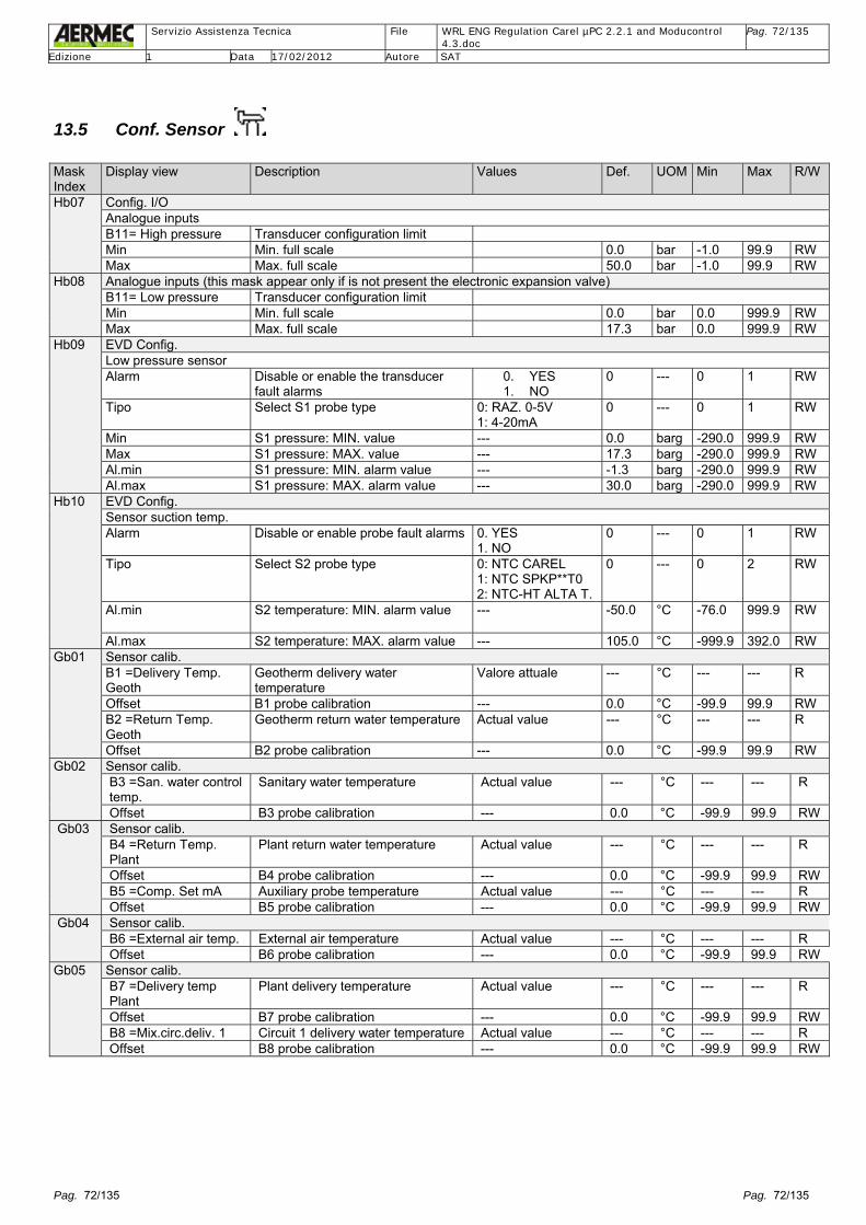
Servizio Assistenza Tecnica File WRL ENG Regulation Carel µPC 2.2.1 and Moducontrol
4.3.doc Pag. 72/135
Edizione 1 Data 17/02/2012 Autore SAT
Pag. 72/135 Pag. 72/135
13.5 Conf. Sensor Mask Index
Display view Description Values Def. UOM Min Max R/W
Hb07 Config. I/O Analogue inputs B11= High pressure Transducer configuration limit Min Min. full scale 0.0 bar -1.0 99.9 RW Max Max. full scale 50.0 bar -1.0 99.9 RW
Hb08 Analogue inputs (this mask appear only if is not present the electronic expansion valve) B11= Low pressure Transducer configuration limit Min Min. full scale 0.0 bar 0.0 999.9 RW Max Max. full scale 17.3 bar 0.0 999.9 RW
Hb09 EVD Config. Low pressure sensor Alarm Disable or enable the transducer
fault alarms 0. YES 1. NO
0 --- 0 1 RW
Tipo Select S1 probe type 0: RAZ. 0-5V 1: 4-20mA
0 --- 0 1 RW
Min S1 pressure: MIN. value --- 0.0 barg -290.0 999.9 RW Max S1 pressure: MAX. value --- 17.3 barg -290.0 999.9 RW Al.min S1 pressure: MIN. alarm value --- -1.3 barg -290.0 999.9 RW Al.max S1 pressure: MAX. alarm value --- 30.0 barg -290.0 999.9 RW
Hb10 EVD Config. Sensor suction temp. Alarm Disable or enable probe fault alarms 0. YES
1. NO 0 --- 0 1 RW
Tipo Select S2 probe type 0: NTC CAREL 1: NTC SPKP**T0 2: NTC-HT ALTA T.
0 --- 0 2 RW
Al.min S2 temperature: MIN. alarm value --- -50.0 °C -76.0 999.9 RW
Al.max S2 temperature: MAX. alarm value --- 105.0 °C -999.9 392.0 RW Gb01 Sensor calib.
B1 =Delivery Temp. Geoth
Geotherm delivery water temperature
Valore attuale --- °C --- --- R
Offset B1 probe calibration --- 0.0 °C -99.9 99.9 RW B2 =Return Temp. Geoth
Geotherm return water temperature Actual value --- °C --- --- R
Offset B2 probe calibration --- 0.0 °C -99.9 99.9 RW Gb02 Sensor calib.
B3 =San. water control temp.
Sanitary water temperature Actual value --- °C --- --- R
Offset B3 probe calibration --- 0.0 °C -99.9 99.9 RW Gb03 Sensor calib.
B4 =Return Temp. Plant
Plant return water temperature Actual value --- °C --- --- R
Offset B4 probe calibration --- 0.0 °C -99.9 99.9 RW B5 =Comp. Set mA Auxiliary probe temperature Actual value --- °C --- --- R Offset B5 probe calibration --- 0.0 °C -99.9 99.9 RW
Gb04 Sensor calib. B6 =External air temp. External air temperature Actual value --- °C --- --- R Offset B6 probe calibration --- 0.0 °C -99.9 99.9 RW
Gb05 Sensor calib. B7 =Delivery temp Plant
Plant delivery temperature Actual value --- °C --- --- R
Offset B7 probe calibration --- 0.0 °C -99.9 99.9 RW B8 =Mix.circ.deliv. 1 Circuit 1 delivery water temperature Actual value --- °C --- --- R Offset B8 probe calibration --- 0.0 °C -99.9 99.9 RW

Servizio Assistenza Tecnica File WRL ENG Regulation Carel µPC 2.2.1 and Moducontrol
4.3.doc Pag. 73/135
Edizione 1 Data 17/02/2012 Autore SAT
Pag. 73/135 Pag. 73/135
Mask Index
Display view Description Values Def. UOM Min Max R/W
Gb06 Sensor calib. B9 =Compres. delivery Discharge gas compressor
temperature Actual value --- °C --- --- R
Offset B9 probe calibration --- 0.0 °C -99.9 99.9 RW Gb07 Sensor calib. (into this mask the B12 probe and its value appear if is not present the exthernal driver of expansion valve)
B11 =Condensation Actual value --- bar --- --- R Offset B11 probe calibration value --- 0.0 bar -99.9 99.9 RW B12 =Evaporation --- bar --- --- R Offset B12 probe calibration value 2 --- 0.0 °C -99.9 99.9 RW
Gb08 Sensor calib. Exp. board pCOe 1 B1:Water temp. zona 2
Water temperature probe zone 2
Offset B1 probe calibration value --- 0.0 °C -3.0 3.0 RW Gb09 Sensor calib.
Exp. board pCOe 2 B1: Water temp. zona 3
Water temperature probe zone 3
Offset B1 probe calibration value --- 0.0 °C -3.0 3.0 RW Gb21 Sensor calib.
EEV Press. Evap Low pressure transducer --- --- bar --- --- R Offset Transducer calibration value --- 0.0 bar -99.9 99.9 RW Temp. Suction Suction temperature probe --- °C --- --- R Offset Probe calibration value 0.0 °C -99.9 99.9 RW
Probe adjust. Room n°01 Temperature Temperature probe --- --- °C --- --- R Offset Probe calibration value --- 0.0 °C -9.9 9.9 RW Humidity Humidity ambient probe --- --- % --- --- R Offset Probe calibration value --- 0.0 % -9.9 9.9 RW
Probe adjust. Room n°02 Temperature Temperature probe --- --- °C --- --- R Offset Probe calibration value --- 0.0 °C -9.9 9.9 RW Humidity Humidity ambient probe --- --- % --- --- R Offset Probe calibration value --- 0.0 % -9.9 9.9 RW
Probe adjust. Room n°03 Temperature Temperature probe --- --- °C --- --- R Offset Probe calibration value --- 0.0 °C -9.9 9.9 RW Humidity Humidity ambient probe --- --- % --- --- R Offset Probe calibration value --- 0.0 % -9.9 9.9 RW
Probe adjust. Room n°04 Temperature Temperature probe --- --- °C --- --- R Offset Probe calibration value --- 0.0 °C -9.9 9.9 RW Humidity Humidity ambient probe --- --- % --- --- R Offset Probe calibration value --- 0.0 % -9.9 9.9 RW
Probe adjust. Room n°05 Temperature Temperature probe --- --- °C --- --- R Offset Probe calibration value --- 0.0 °C -9.9 9.9 RW Humidity Humidity ambient probe --- --- % --- --- R Offset Probe calibration value --- 0.0 % -9.9 9.9 RW
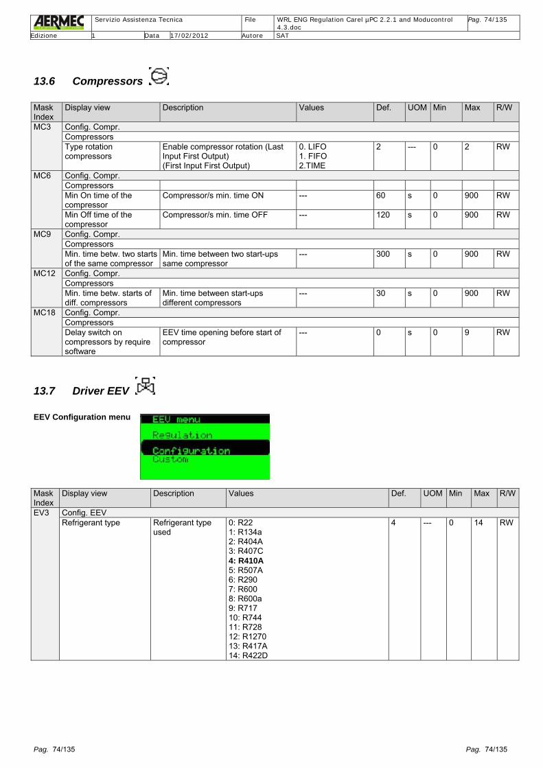
Servizio Assistenza Tecnica File WRL ENG Regulation Carel µPC 2.2.1 and Moducontrol
4.3.doc Pag. 74/135
Edizione 1 Data 17/02/2012 Autore SAT
Pag. 74/135 Pag. 74/135
13.6 Compressors Mask Index
Display view Description Values Def. UOM Min Max R/W
MC3 Config. Compr. Compressors Type rotation compressors
Enable compressor rotation (Last Input First Output) (First Input First Output)
0. LIFO 1. FIFO 2.TIME
2 --- 0 2 RW
MC6 Config. Compr. Compressors Min On time of the compressor
Compressor/s min. time ON --- 60 s 0 900 RW
Min Off time of the compressor
Compressor/s min. time OFF --- 120 s 0 900 RW
MC9 Config. Compr. Compressors Min. time betw. two starts of the same compressor
Min. time between two start-ups same compressor
--- 300 s 0 900 RW
MC12 Config. Compr. Compressors Min. time betw. starts of diff. compressors
Min. time between start-ups different compressors
--- 30 s 0 900 RW
MC18 Config. Compr. Compressors Delay switch on compressors by require software
EEV time opening before start of compressor
--- 0 s 0 9 RW
13.7 Driver EEV EEV Configuration menu Mask Index
Display view Description Values Def. UOM Min Max R/W
EV3 Config. EEV Refrigerant type Refrigerant type
used 0: R22 1: R134a 2: R404A 3: R407C 4: R410A 5: R507A 6: R290 7: R600 8: R600a 9: R717 10: R744 11: R728 12: R1270 13: R417A 14: R422D
4 --- 0 14 RW

Servizio Assistenza Tecnica File WRL ENG Regulation Carel µPC 2.2.1 and Moducontrol
4.3.doc Pag. 75/135
Edizione 1 Data 17/02/2012 Autore SAT
Pag. 75/135 Pag. 75/135
Mask Index
Display view Description Values Def. UOM Min Max R/W
EV6 Config. EEV Main regulation Regulation type 0: USER DEFINE
1: AC/CHILLER WITH ADAPT. REGULATION 2: AC/CHILLER WITH DIG. SCROLL COMPRESSOR 3: CENTRALIZED CABINET COLD ROOM 4: SELF CONTAINED CABINET COLD ROOM 5: PERTURBATED CABINET COLD ROOM 6: SUBCRITICAL CO2 CABINET/COLD ROOM 7: R404A CONDENSER FOR SUBCRITICAL CO2 8: AC OR CHILLER WITH PLATE EVAPORATOR 9: AC OR CHILLER WITH SHELL TUBE EVAPORATOR 10: AC OR CHILLER WITH BATTERY COIL EVAPORATOR. 11: AC OR CHILLER WITH VAR. COOLING CAPACITY 12: AC OR CHILLER PERTURBATED UNIT 13: EPR BACK PRESSURE 14: HOT GAS BY-PASS BY PRESSURE 15: HOT GAS BY-PASS BY TEMPERATURE 16: TRANSCRITICAL CO2 GAS COOLER 17: ANALOG POSITIONER (4-20MA)
0 --- 0 17 RW
Auxiliary regulation Auxiliary regulation type
0: USER DEFINE 1: DISABLED 2: HIGH CONDENSING TEMP.PROTECTION ON S3 3: MODULATING THERMOSTAT ON S4 PROBE 4: BACKUP PROBES ON S3 AND S4
0 --- 0 4 RW
EEV Regulation menu Mask Index
Display view Description Values Def. UOM Min Max R/W
ER3 EEV Regulation Valve opening at start-up
Open valve at start-up rated value (EVAP/EEV capacity ratio) 50% con 1
solo compressore, 80% con 2 compressori
50/ 80
% 0 200 RW
Time start-up Time start-up forced to pre-position Only for ON BOARD expansion valve managed from Carel µPC control board
5 s 0 999 RW
ER6 EEV Regulation Valve opening in stand-by
Expansion valve opening in stand-by condition of unit (unit in Off)
0. NO 1. YES
0 0 1 RW
ER9 EEV Regulation PID parameters Prop. gain Proportional gain ONBOARD = 5.0 15.0 --- 0 800 RW Integral time Integral time ONBOARD = 60 150 s 0 1000 RW Derivat. time Derivative time ONBOARD = 1.0 5.0 s 0 800 RW

Servizio Assistenza Tecnica File WRL ENG Regulation Carel µPC 2.2.1 and Moducontrol
4.3.doc Pag. 76/135
Edizione 1 Data 17/02/2012 Autore SAT
Pag. 76/135 Pag. 76/135
Mask Index
Display view Description Values Def. UOM Min Max R/W
ER12 EEV Regulation Setpoint SH Superheating Set point of
expansion electronic valve 6.0 K 0 99.9
LowSH thresh. Activation threshold Low SH to prevent liquid refrigerant gas return to the compressor/s
Low superheating 2.0 K -99.9 99.9 RW
LOP thresh. Activation threshold Low pressure evaporation to prevent low suction temperature
LOP= Low Operating Pressure
-2.0 °C -99.9 99.9 RW
MOP thresh. Activation threshold high pressure evaporation to prevent high suction temperature
MOP= Maximum Operating Pressure.
15.0 °C -99.9 99.9 RW
ER15 EEV Regulation Integral time LowSH protect. Integral time indicate the intensity
of the protection actions: more is lower bigger will be the intensity
0= action disabled 10.0 s 0 800 RW LOP protection 10.0 s 0 800 RW MOP protection 20.0 s 0 800 RW
ER18 EEV Regulation Alarm delay LowSH 0= action disabled 300 s 0 18000 RW LOP 300 s 0 18000 RW MOP 600 s 0 18000 RW
ER21 EEV Regulation Alarm low suction temperature
Threshold 2.0 °C -76.0 392.0 RW Timeout 300 s 0 18000 RW
EEV Custom menu Mask Index
Display view Description Values Def. UOM Min Max R/W
EC1 Config. EEV Valve type
Electronic expansion valve type, installed since WRL 160 size included
0: CAREL E2V 1: DANFOSS/ SAGINOMYA TYPE KV 2: SPORLAN ESX 3: ALCO EXM/EXL 4: SANHUA L SERIES5: HUALU DPF 12V 6: HUALU SPF 12V 7: HUALU EPF-VPF 12V
0 --- 0 7 RW

Servizio Assistenza Tecnica File WRL ENG Regulation Carel µPC 2.2.1 and Moducontrol
4.3.doc Pag. 77/135
Edizione 1 Data 17/02/2012 Autore SAT
Pag. 77/135 Pag. 77/135
Mask Index
Display view Description Values Def. UOM Min Max R/W
EC1 Config. EEV Valve type
Electronic expansion valve type, installed from WRL 180 size included
0: CAREL ExV 1: ALCO EX4 2: ALCO EX5 3: ALCO EX6 4: ALCO EX7 5: ALCO EX8 330Hz CONSIGLIATA CAREL6: ALCO EX8 500Hz SPECIFICA ALCO 7: SPORLAN SEI 0.5-11 8: SPORLAN SER 1.5-20 9: SPORLAN SEI 30 10: SPORLAN SEI 50 11: SPORLAN SEH 100 12: SPORLAN SEH 175 13: Danfoss ETS 12.5-25B 14: DANFOSS ETS 50B 15: DANFOSS ETS 100B 16: DANFOSS ETS 250 17: DANFOSS ETS 400
0 --- 0 17 RW
EC3 Valve Custom Min. steps 50 stp 0 999 RW Max. steps 480 stp 0 999 RW Closing steps 500 stp 0 999 RW
EC6 Valve Custum Speed nominal Nominal speed
Check that the value must be setted to 50Hz
50 Hz 1 999 RW
Speed closing --- Hz --- --- --- Target current 450 Hz 0 800 RW Holding current Holding current 100 mA 0 800 RW
EC9 Valve Custum Duty cycle: Duty cycle 30 % 0 100 RW Opening synchr. Electronic expansion valve
syncrounism in opening status 0. NO 1. YES
1 --- 0 1 RW
Opening synchr. Electronic expansion valve syncrounism in closing status
0. NO 1. YES
1 --- 0 1 RW
13.8 Options Mask Index
Display view Description Values Def. UOM Min Max R/W
Hd02
Varius Change password Personalize various
password
Manufactory 202 0 9999 RW Service 101 0 9999 RW Wizard 303 0 9999 RW

Servizio Assistenza Tecnica File WRL ENG Regulation Carel µPC 2.2.1 and Moducontrol
4.3.doc Pag. 78/135
Edizione 1 Data 17/02/2012 Autore SAT
Pag. 78/135 Pag. 78/135
13.9 Default Mask Index
Display view Description Values Def. UOM Min Max R/W
Hd01
Initialization DEFAULT INSTALLATION Erase user settings and install factory
Allows to reset default values
--- --- --- --- --- RW
Legend: Explanation about beginning squares of parameters columns: Mask Index
Display view Description Values Def. UOM Min Max R/W
Mask Index: Index signature about the mask views on the display up right corner side (example) Display view: Parameters and them values views Description: Parameters description views Values: All values that is possible insert in replace to the default parameters Def.: Default value UOM: Unit measure type Min: Minimum value that is possible insert on the parameter respect the default Max: Maximum value that is possible insert on the parameter respect the default R/W: Parameter views to read (R= Read) and/or modification (W= Write)
IMPORTANT: From software version 2.3.0 it is possible to directly access the Assistance sub-menu of the Menu User simply by pressing the key. The access method to the Menu User sub-menus and to the Menus Wizard (password 0303), Set-up procedure (password 0009), Assistance (password 0101) and Manufacturer (password 0202) remain as described in the screens of pages 26 and 27.

Servizio Assistenza Tecnica File WRL ENG Regulation Carel µPC 2.2.1 and Moducontrol
4.3.doc Pag. 79/135
Edizione 1 Data 17/02/2012 Autore SAT
Pag. 79/135 Pag. 79/135
14 Room sensor accessory STA/STH (Carel Th_Tune)
For each room a user terminal th_tune (STA/H) can be installed. As standard it has an internal temperature sensor and can have a humidity sensor. Powered by 230 Volt
The various functions are detailed below:
Address to configure STA connected 1 Zone 1, Room 1 2 Zone 2, Room 1 3 Zone 2, Room 2 4 Zone 3, Room 1 5 Zone 3, Room 2
To change the ModBus address of the room sensor (STA/H) press the keys FAN+POWER for 3 sec, insert the password 22 and change the parameter “Addr”.
Actual season
Small area Shows time of µPC or humidity of STA
ON/OFF room key
Lack of hot water
Lack of cold water Room pump on
Forced off by time-clock
Big area Shows temperature or actual setpoint
At least one alarm present
Deumidification active

Servizio Assistenza Tecnica File WRL ENG Regulation Carel µPC 2.2.1 and Moducontrol
4.3.doc Pag. 80/135
Edizione 1 Data 17/02/2012 Autore SAT
Pag. 80/135 Pag. 80/135
15 pCOe Expansion board The Carel µPC board does not have sufficient input/outputs for all the functions.
The software therefore requires expansion input/outputs called pCOe (expansion boards) to meet the requirements of other functions (see section 3.4.1.1 Zone Control and 3.4.1.2 Drycooler Control). The pCOe boards can be powered by 24 Volt alternating or direct current. For the electrical connection see section 5.1 “Table of devices controlled on the ModBus network”.
The table detailed shows the addresses of the variables within the pCOe expansion board. Type of data Address Variable
Register 19 Temperature sensor 1 Register 20 Temperature sensor 2 Register 21 Temperature sensor 3 Register 22 Temperature sensor 4 30 Status digital input 1 31 Status digital input 2 32 Status digital input 3 33 Status digital input 4 Register 51 Analogue output 1 69 Relay 1 70 Relay 2 71 Relay 3 72 Relay 4

Servizio Assistenza Tecnica File WRL ENG Regulation Carel µPC 2.2.1 and Moducontrol
4.3.doc Pag. 81/135
Edizione 1 Data 17/02/2012 Autore SAT
Pag. 81/135 Pag. 81/135
16 Regulation
16.1 Chiller/Heat pump The application provides control of a water/water heat pump which can have up to two compressors in one refrigerant circuit. These can produce either hot or cold water for the system, based on the active seasonal mode and hot water for the DHW circuit. It controls up to two compressors in one refrigerant circuit which alternate using a rotation type FIFO (First In First Out). It controls the safety timers of the compressor and the relative pumps. For further information see the sections relevant in the Menu Service and Manufacturer. The unit can be supplied with an electronic expansion valve EEV, which below side WRL160 is directly controlled, whilst above this size requires the driver EVO. The guided installation (Menu Wizard) allows an easy configuration of the WRL once installed.
16.1.1 Control of the system side water The Carel µPC board controls the return water temperature of the system, or the outlet temperature (adjustable parameter). The control is divided between hot water production (winter), and cold water production (summer). The operational values are adjustable from the Menu Service sub-menu Chiller.
In the following diagrams the winter temperature control of the compressors (in the cases of 1 or 2 compressors); the summer operation is reversed and relative to the chilled water setpoint. Control can be either just proportional or proportional and integral.
In the winter operating mode of the primary circuit the supplementary heaters used (digital output NO6) are either heating elements inserted in the heat exchanger or a boiler. The temperature control of the chiller can be enabled even on the demand of a single zone. There are timers to ensure the correct functioning of the chiller. In the summer heating mode the outlet sensor of the primary circuit provides anti-freeze protection (see also the section dedicated to the anti-freeze function) of the unit’s heat exchanger.
16.1.2 Reversing control of the refrigerant circuit / water-side The WRL units can produce hot or cold water (heating or cooling mode), through a refrigerant reversing valve (heat pump unit); in this mode the flow of refrigerant is reversed in the heat exchangers (system and geothermal); alternatively installing a four way water-side valve for reversing the unit. 1. Reversing the refrigerant circuit

Servizio Assistenza Tecnica File WRL ENG Regulation Carel µPC 2.2.1 and Moducontrol
4.3.doc Pag. 82/135
Edizione 1 Data 17/02/2012 Autore SAT
Pag. 82/135 Pag. 82/135
2. Reversing water-side To reverse the cycle enter the Menu On/Off, turn off the unit and reverse the selection of the function in the same screen. The reversible unit is configurable in the Menu Service, in the sub-menu Conf.System.
The compressor(s) are always off during the change of mode.
16.1.3 Control of the system pump
The Carel µPC board has a digital output NO3 (terminal J12) to control a system pump. This is normally on when the unit status is ON. It is possible through screen P3 of the sub-menu Pump in the Menu Service to select pump ON with compressor demand. In this mode when the system thermostat demands the pump is enabled and the compressors are started after the normal timers.
If “ON COMP DEMAND” is selected it is recommended to select the control type as entering and to mount the inlet sensor B4 on the system buffer tank.
16.1.4 Control of geothermal pump The Carel µPC board has a digital output NO2 (terminal J12) to control the geothermal pump, as well as a 0-10 Volt output (Y2 terminal J5) to control a pump speed or throttling valve. The control of the pump can be: Type of control Geothermal heat exchanger as Evaporator Geothermal heat exchanger as Condenser Control compressors ON Output Y2 fixed, Pump ON Output Y2 variable, controls on outlet pressure and
differential Control on pressure Output Y2 fixed, Pump ON Output Y2 variable, controls on outlet pressure and
differential Control on geothermal side return water temperature
Set - differential = maximum speed Temperature above set = pump off
Set + differential = maximum speed Temperature below set = pump off
Control on geothermal side outlet water temperature
Set - differential = maximum speed Temperature above set = pump off
Set + differential = maximum speed Temperature below set = pump off

Servizio Assistenza Tecnica File WRL ENG Regulation Carel µPC 2.2.1 and Moducontrol
4.3.doc Pag. 83/135
Edizione 1 Data 17/02/2012 Autore SAT
Pag. 83/135 Pag. 83/135
Before the compressor(s) start a minimum time from the start of the geothermal pump must pass, after the compressor(s) stop a time delay must pass to stop the geothermal pump. All the parameters are accessible in the sub-menu Pumps entering the Menu Service.
Control with condensing pressure Valv %= Speed of inverter or percentage open of the modulating valve HP= Value of the high pressure read from the transducer Max= Maximum inverter speed Min = Minimum inverter speed Set = Condensing setpoint Diff = Control differential
In total heat recovery mode (for DHW) the geothermal pump will always control with reference to the condensing pressure to avoid it dropping too.
16.1.5 Control of the alarms relating to the refrigerant circuit The Carel µPC board control the alarms of the compressor(s) exactly as: Alarm Cause Delay Reset Action Compressor thermal cut‐out Digital Input 2 and 9 No Manual Switch off compressor Pressostat high pressure Digital Input 4 No Manual Switch off compressor High pressure from HP Pressure B11 YES Manual Switch off compressor Low pressure 1 from LP Pressure B12 YES Automatic / Manual Switch off compressor Low pressure from LP lack of refrigerant Pressure B12 YES Manual Switch off compressor High temperature compressor discharge Temperature B9 YES Automatic Switch off compressor The low pressure alarm from the transducer is automatic reset for five attempts; the successive attempt becomes manual reset.
After restoration of power loss if the evaporating pressure is below 2.0 bar the electronic expansion valve EEV opens for 5 seconds to attempt to equalise pressures. This avoids the problem of resetting the serious alarm of low pressure.
All parameters regarding the safeties are found in the sub-menu Conf.Alarm in the Menu Factory.
16.1.6 Control of alarms relating to the hydraulic installation (system, geothermal, DHW) The Carel µPC board can control up to three pumps: one system pump, one geothermal pump and one dedicated to the DHW. Additionally two anti-freeze heating elements can be controlled which can also be used as supplementary heaters. The safeties connected to these pumps are: Alarm Cause Delay Reset Action Pump thermal cut‐out Digital Input 4 No Automatic Switch off all pumps Geothermal flow switch Digital Input 1 Start + run Automatic / manual Switch off geothermal pump System flow switch Digital Input 10 Start + run Automatic / manual Switch off system pump Geothermal anti‐freeze Temperature B1 or B2 No in cool / Yes in heat Selectable Switch off compressor System anti‐freeze Temperature B3 or B4 No in cool / Yes in heat Selectable Switch off compressor DHW tank immersion heater thermal cut‐out
Digital Input 6 No Automatic Switch off DHW immersion heater
System heater thermal cut‐out Digital Input 7 No Automatic Switch off boiler/electric heater External alarm to pCOe Digital Input 1 pcoe No Yes Switch off everything For the control of the system water flow switch either manual or automatic reset can be selected; in the automatic case five resets are allowed after which manual reset is required.
In the case of a reversible installation (with water-side reversing and external pump) the geothermal flow switch becomes the system flow switch and vice-versa.
All parameters regarding the safeties are found in the sub-menu Conf.Alarm in the Menu Factory.
Set
Min
Max
Valv[%]
HP[bar]
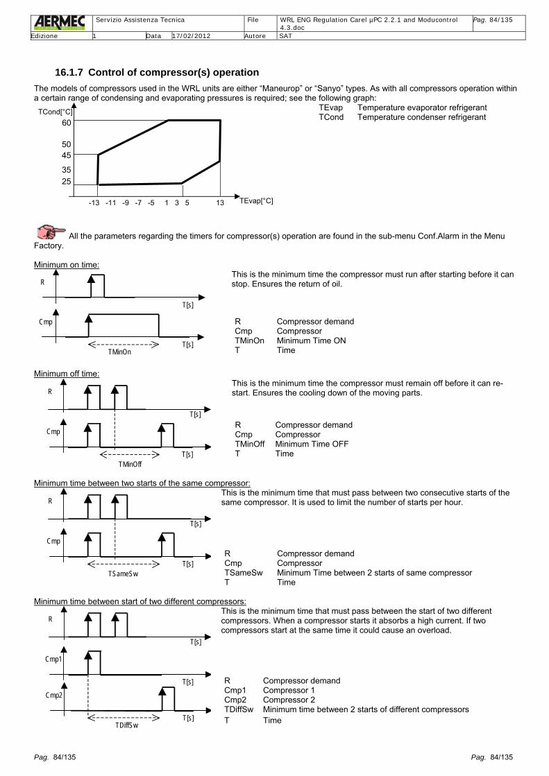
Servizio Assistenza Tecnica File WRL ENG Regulation Carel µPC 2.2.1 and Moducontrol
4.3.doc Pag. 84/135
Edizione 1 Data 17/02/2012 Autore SAT
Pag. 84/135 Pag. 84/135
16.1.7 Control of compressor(s) operation The models of compressors used in the WRL units are either “Maneurop” or “Sanyo” types. As with all compressors operation within a certain range of condensing and evaporating pressures is required; see the following graph:
TEvap Temperature evaporator refrigerant TCond Temperature condenser refrigerant
All the parameters regarding the timers for compressor(s) operation are found in the sub-menu Conf.Alarm in the Menu Factory. Minimum on time:
T[s]
R
T[s]
Cmp
TMinOn
This is the minimum time the compressor must run after starting before it can stop. Ensures the return of oil.
R Compressor demand
Cmp Compressor TMinOn Minimum Time ON T Time
Minimum off time:
T[s]
R
T[s]
Cmp
TMinOff
This is the minimum time the compressor must remain off before it can re-start. Ensures the cooling down of the moving parts.
R Compressor demand Cmp Compressor TMinOff Minimum Time OFF T Time
Minimum time between two starts of the same compressor:
T[s]
R
T[s]
Cmp
TSameSw
This is the minimum time that must pass between two consecutive starts of the same compressor. It is used to limit the number of starts per hour.
R Compressor demand Cmp Compressor TSameSw Minimum Time between 2 starts of same compressor T Time
Minimum time between start of two different compressors:
T[s]
R
T[s]
Cmp1
T[s]
Cmp2
TDiffSw
This is the minimum time that must pass between the start of two different compressors. When a compressor starts it absorbs a high current. If two compressors start at the same time it could cause an overload.
R Compressor demand
Cmp1 Compressor 1 Cmp2 Compressor 2 TDiffSw Minimum time between 2 starts of different compressors T Time
-13 -11 -9 -7 -5 1 3 5 13
25 35
45 50
60
TEvap[°C]
TCond[°C]
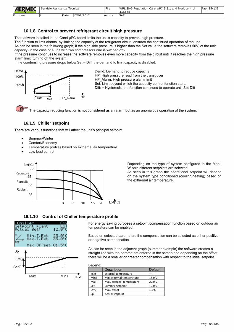
Servizio Assistenza Tecnica File WRL ENG Regulation Carel µPC 2.2.1 and Moducontrol
4.3.doc Pag. 85/135
Edizione 1 Data 17/02/2012 Autore SAT
Pag. 85/135 Pag. 85/135
16.1.8 Control to prevent refrigerant circuit high pressure The software installed in the Carel µPC board limits the unit’s capacity to prevent high pressure. The function to limit alarms, by limiting the capacity of the refrigerant circuit, ensures the continued operation of the unit. As can be seen in the following graph, if the high side pressure is higher than the Set value the software removes 50% of the unit capacity (in the case of a unit with two compressors one is witched off). If the pressure continues to increase the software removes even more capacity from the circuit until it reaches the high pressure alarm limit, turning off the system. If the condensing pressure drops below Set – Diff, the demand to limit capacity is disabled.
The capacity reducing function is not considered as an alarm but as an anomalous operation of the system.
16.1.9 Chiller setpoint There are various functions that will affect the unit’s principal setpoint
• Summer/Winter • Comfort/Economy • Temperature profiles based on exthernal air temperature • Low load control
Depending on the type of system configured in the Menu Wizard different setpoints are selected. As seen in this graph the operational setpoint will depend on the system type conditioned (cooling/heating) based on the exthernal air temperature.
16.1.10 Control of Chiller temperature profile
For energy saving purposes a setpoint compensation function based on outdoor air temperature can be enabled. Based on selected parameters the compensation can be selected as either positive or negative compensation.
As can be seen in the adjacent graph (summer example) the software creates a straight line with the parameters entered in the screen and depending on the offset there will be a smaller or greater compensation with respect to the initial setpoint. Legend:
Description Default TExt External temperature ‐‐‐ MinT Min. external temperature 15.0°C MaxT Max. external temperature 22.0°C SetE Summer setpoint 12.0°C OffS Max. offset 1.5°C Sp Actual setpoint ‐‐‐
Demd: Demand to reduce capacity HP: High pressure read from the transducer HP_Alarm: High pressure alarm limit Set: Limit beyond which the capacity control function starts Diff: = Hysteresis, the function continues to operate until Set-Diff
20
25
35
45
55
TExt[°C]
Stp[°C]
0 5 1510
Radiators
Fancoils
Radiant
HP
Demd
50%h
100%
Diff Set HP_Alarm
TExt
Sp
SetE
OffS
MaxT MinT

Servizio Assistenza Tecnica File WRL ENG Regulation Carel µPC 2.2.1 and Moducontrol
4.3.doc Pag. 86/135
Edizione 1 Data 17/02/2012 Autore SAT
Pag. 86/135 Pag. 86/135
16.1.11 Control of system supplementary heating with electric heater or boiler The software can control a supplementary heating installation with electric heaters or boiler or eventually a solar thermal kit.
T [°C]
Boi ler
Diff Set
ON
If a boiler is configured as present this can operate in place, of or in addition to thecompressor(s). In the case of a replacement operating mode the compressor(s) cannot run at the same time as the boiler. In the case of supplementary operating mode compressors can run and the boiler canrun in support. The boiler can be activated based on the geothermal return water temperature or based on the outdoor air temperature. In any case there will always be a delay timer when enabling the boiler. Boiler= Boiler T= Geothermal return water temperature or outdoor air temperature Set = Setpoint, screen B15 in the sub-menu Accessory in the Menu Service Diff= Differential, screen B15 in the sub-menu Accessory in the Menu Service
T [°C]
Heater
DiffOf SetDiffON
O N
If an electric heater is configured as present this will always operate in support of thecompressor(s). There will always be a delay timer when enabling the electric heater Heater = Heater T= System return water temperature Set = Principal setpoint Diff Off = Differential Off, screen B18 in sub-menu Accessory in the Menu Service Diff On = Differential On, screen B18 in sub-menu Accessory in the Menu Service
Through digital input ID7 (terminal J4 of the Carel µPC board) which serves as thermal cut-out for the heater/boiler, the alarms of the electric heater or boiler supporting the system can be controlled.
16.2 Control of DHW Through the Carel µPC board the software can control a DHW tank.
The type of control can be selected from the screens found in the sub-menu Conf.system in the Menu Service. The DHW tank can be controlled as:
• Desuperheater • Total heat recovery with DHW priority • Priority with mixing valve • Priority with DHW pump in parallel to the system pump
The demand for DHW production comes from a thermostat request and functions based on setpoint, DHW temperature and range, with reference to the sensor B3 (terminal J3 of the Carel µPC board). The demand for compressor(s) is based on the system outlet temperature or of the total heat recovery outlet temperature.
DHW only operation can be forced from the screen in the sub-menu On/Off in the Menu User, or through the digital input ID4 terminal J4 adding and additional pCOe expansion board.
The active setpoint does not change with the change of season.
The control of the DHW valve, output Y1 (terminal J5 of the Carel µPC board), follows the same logic of output NO4 (terminal J13) but with a modulating proportional control based on the parameters found in the sub-menu DHW in the Menu Service.

Servizio Assistenza Tecnica File WRL ENG Regulation Carel µPC 2.2.1 and Moducontrol
4.3.doc Pag. 87/135
Edizione 1 Data 17/02/2012 Autore SAT
Pag. 87/135 Pag. 87/135
16.2.1 Control of the desuperheater in cooling only mode The desuperheater is a heat exchanger installed in the compressor(s) discharge piping and partially recovers the discharge heat directly after the compression phase during cooling mode operation of the unit (remember that the complete condensing phase of the compressed refrigerant occurs in the condenser). Therefore heat recovery from the desuperheater is linked to the production of chilled water for the system by a demand for the unit to run. The installer can decide whether to use the DHW pump to obtain the benefit of the heat of compression through the desuperheater. The DHW pump NO4 (terminal J13) is on only if the compressor(s) are operating and the unit is in summer mode. The DHW pump NO4 (terminal J13) can operate either through the demand from the sensor B3 (SSAN DHW sensor), or acting on the parameter P18 in the sub-menu Pumps of the Menu Service, “activation DHW pump in summer” selecting the option of when compressors run.
16.2.2 Control of the total heat recovery The WRL unit with total heat recovery are made up of three heat exchangers: system, geothermal and DHW, generally of equal sizes. Whilst for the cooling only unit with desuperheater the partial heat recovery function is linked to the demand of the system thermostat. For the heat pump unit with total heat recovery the controls operate as follows:
Through the refrigerant reversing valve the system and geothermal heat exchangers can exchange roles of evaporator and condenser based on the requested functioning mode. The DHW heat exchanger always remains a condenser. The DHW demand is always priority so the unit always satisfies the DHW based on the setpoint and temperature read at the DHW tank sensor (SSAN), then satisfies the system demand. In heating function the system pump remains switched off when there is a DHW demand and the geothermal heat exchanger acts as the evaporator. In cooling function if there is a simultaneous demand for DHW and for system cold water the geothermal pump is switched off and the system heat exchanger acts as the evaporator. Once the DHW demand is satisfied the unit will operate in cooling or in heating mode based on the operating mode configuration. During changes of functions the compressor and reversing cycle timers are always respected.
B3 NO1 ID2
NO2 ID4 Y2
NO3 ID4 B1
B2
NO10 NO4 ID4 Y1
GEO

Servizio Assistenza Tecnica File WRL ENG Regulation Carel µPC 2.2.1 and Moducontrol
4.3.doc Pag. 88/135
Edizione 1 Data 17/02/2012 Autore SAT
Pag. 88/135 Pag. 88/135
The following table details the functional characteristics in total heat recovery: Condition Winter case Pump On/Off Pump inverter Default 1 System heating demand Geothermal (Evaporator)
System (Condenser) DHW
ON ON OFF**
Fixed speed Not controlled OFF
80%
2 DHW heating demand Geothermal (Evaporator) System (Condenser) DHW
ON OFF** ON
Fixed speed Not controlled High Pressure control*
80% 18bar ->30.0°C
Condition Summer case Pump On/Off Pump inverter Default 1 System cooling demand Geothermal (Condenser)
System (Evaporator) DHW
ON ON OFF**
High Pressure control Not controlled Forced
25bar ->42.7°C
2 System cooling demand + DHW heating demand
Geothermal (Condenser) System (Evaporator) DHW
OFF** ON ON
High Pressure control Not controlled High Pressure control
25bar ->42.7°C 18bar ->30.0°C
3 DHW heating demand Geothermal (Evaporator) System (Condenser) DHW
ON OFF** ON
High Pressure control Not controlled High Pressure control*
25bar ->42.7°C 18bar ->30.0°C
* Setpoint and differential found in parameter Q21 in the sub-menu DHW in the Menu Service ** Can switch on if the evaporating pressure drops below the low pressure setpoint of 7.0bar (0°C), see parameter P34 in the sub-menu Pumps in the Menu Service
From software version 1.9 it is possible to use a sensor in the heat recovery outlet (selectable) to control the demand for compressor(s) operation. The setpoint and differential are found in the parameter Q30 in the sub-menu DHW in the Menu Service. The enabling and control of the DHW remains unchanged.
16.2.3 Control of the DHW (priority) with 3 way device valve The device valve is a water-side valve located downstream of the unit’s system heat exchanger. The device valve diverts the water either towards the system/system buffer tank or towards the DHW. In the case of DHW demand: - compressor(s) on are switched off, respecting compressor timers - system/sanitary pump is switched off (output NO3,remind, it is used the same pump for system and sanitary water because is presente the three way device valve from system to sanitary) - the three way device valve is activated (output NO4) - wait for an adjustable delay timer (parameter Q12 in the sub-menu DHW in the Menu Service) that allows the valve to position towards the DHW tank - system/sanitary pump is switched on (output NO3,remind, it is used the same pump for system and sanitary water because is presente the three way device valve from system to sanitary) - geothermal pump is switched on (output NO2) - the reversing valve is forced into heat pump mode (if it is not already) - compressor(s) restart based on the sensor entered in parameter Mq3 in the sub-menu DHW of the Menu Factory - once the DHW demand is satisfied the above operations are repeated and position the device valve towards the system buffer tank
16.2.4 Control of the DHW (priority) with DHW pump The DHW pump is a pump located downstream of the unit’s system heat exchanger in parallel with the system/system buffer pump. The two pumps operate alternately to each other. In the case of DHW demand: - compressor(s) on are switched off, respecting compressor timers - system pump is switched off (output NO3), ignoring the stop delay timer - geothermal pump remains on (output NO2) - DHW pump is switched on (output NO4) - the reversing valve is forced into heat pump mode (if it is not already) - compressor(s) restart based on the sensor entered in parameter Mq3 in the sub-menu DHW of the Menu Factory - once the DHW demand is satisfied the above operations are repeated and the system pump is switched on in case of demand

Servizio Assistenza Tecnica File WRL ENG Regulation Carel µPC 2.2.1 and Moducontrol
4.3.doc Pag. 89/135
Edizione 1 Data 17/02/2012 Autore SAT
Pag. 89/135 Pag. 89/135
16.2.5 Control of the DHW pump of inverter type or modulating valve The Carel µPC board has as standard a digital output NO4 to control a pump ON/OFF and an output Y1 to control variable pump speed or a modulating valve (throttling) on to the sanitary side. In DHW mode when the DHW pump starts low pressure in the DHW heat exchanger could occur, which is acting as a “condenser”, causing a low condensing pressure. To avoid this it is advantageous to have a DHW pump of inverter type or a modulating valve to maintain an adequate condensing pressure. The setpoint and differential values and the values for minimum and maximum pump speed/valve opening are contained in parameter Q21 found in the sub-menu DHW of the Menu Service.
Inv(%)= percentage speed of the pump inverter or percentage opening of the modulating valve Max= Maximum pump speed/valve opening Min = Minimum pump speed/valve opening Setpoint= Minimum pressure value below which the pump inverter runs at minimum speed (eventually stops)/modulating valve starts to close Diff = Differential
16.2.6 Control of the DHW pump ON/OFF
To maintain condensing control during DHW functioning an alternative to a pump inverter an ON/OFF pump control function can be selected where the operation is based on not just on the thermostatic demand with reference to the water temperature of sensor B3, but also taking into account the values inserted in the parameter Q21 found in the sub-menu DHW of the Menu Service.
In this case the following function occurs: • DHW demand for hot water • Reversing cycle to winter mode or total heat recovery • Start of the DHW pump and eventually geothermal and system pumps • Delayed start of the compressor(s) • Stop the DHW pump based on low condensing pressure • Start the DHW pump to raise condensing pressure • Starting and stopping the pump to bring the condensing pressure to an acceptable value
Clearly during these phases the safeties of the compressor always remain active.
The choice to make the DHW pump operate immediately after a demand for DHW or only after starting compressor(s) is selectable in parameters P18 found in the sub-menu Pumps of the Menu Service.
For units fitted with the electronic expansion valve (digit X in the configurator) the operation of the DHW pump with condensing pressure control must not be selected, because the LOP, internal algorithm controlling the electronic expansion valve, will ensure the condensing pressure is maintained within normal operating values.
16.2.7 Control of the condenser pump during heat recovery When the heat recovery heat exchanger operates the other heat exchanger used as the condenser in the refrigerant circuit is not used, then its may be or the system heat exchanger during heat pump mode operation or the geothermal heat exchanger during cooling mode operation. Vice-versa, when the heat exchanger used as condenser is operating the heat recovery heat exchanger is not used. In particular during the last situation described, taking into account that the heat recovery heat exchanger is not operating since the DHW temperature is satisfied; if during operation the evaporating pressure should drop below 7.0 bar (0°C) the pump is started relating to the heat exchanger that is off and will stop at 7.5 bar (1.6°C). This operation permits the heat of the hot water in the heat exchanger not operating to be used to raise the condensing pressure and as a consequence the evaporating pressure. The forced starting of the pump for the heat exchanger not operating will not be activated if the inlet water temperature is too low.
Parameter P34 found in the sub-menu Pumps of the Menu Service. The forcing of the pump for the heat exchanger not operating operates in this mode: NO: function not enabled WINTER ONLY: to avoid sending hot water to the system during summer operation ALWAYS: whenever heat recovery is operating this function is always active
HP[bar]
Inv[%]
Mi
Max
Diff Stp
Pump

Servizio Assistenza Tecnica File WRL ENG Regulation Carel µPC 2.2.1 and Moducontrol
4.3.doc Pag. 90/135
Edizione 1 Data 17/02/2012 Autore SAT
Pag. 90/135 Pag. 90/135
16.2.8 Control of the anti-legionella treatment From the DHW menu found in the Menu User, it is possible to activate (if a supplementary system is enabled in the Menu Wizard screens K18 and K21) a weekly algorithm for anti-legionella treatment. Through the output of the board NO8 a supplementary system can be activated (boiler or immersion heater) to heat the DHW so that raising the temperature avoids problems associated with the proliferation of the Legionella bacteria. This function is only available if the immersion heater within the DHW tank is enabled (screens K18 and K21 of the Menu Wizard). This function is active even with the unit off.
Entering in parameter Q15 of the sub-menu DHW of the Menu Service allows: - insertion of the start time of the anti-legionella function - the days of the week it is activated - decide whether to disable
To stop the treatment the DHW temperature B3 must remain above the setpoint for a minimum time of 5 minutes (adjustable). If the treatment does not stop within the maximum time of 120 minutes (adjustable) an alarm is generated and the anti-legionella function is interrupted
It is possible to force the anti-legionella function entering in parameter M27 of the sub-menu Manual of the Menu Service.
16.2.9 Control of the DHW time-clock The operation can be enabled or disabled by the DHW daily time-clock. If in the menu DHW contained in the Menu User the DHW time-clock is enabled (screen D6) up to 4 daily programmes for the 7 days of the week can be programmed.
16.2.10 DHW Alarms Alarm Cause Delay Reset Action High DHW temperature Temperature B3 60s Automatic Display only of value fixed at 75°C DHW anti‐freeze Temperature B3 Adjustable Automatic Manual Switch on tank immersion heater Pumps thermal cut‐out Digital Input 4 No Automatic Switch off all pumps
16.2.11 Control of DHW supplementary heating with immersion heater or boiler The WRL system can have a supplementary DHW heater with immersion heater or boiler.
T [° C]
Bo iler
Diff Set
O N
If boiler is selected this can operate as a replacement or as supplementary heater. In the case of replacement the compressor(s) cannot be active together with the boiler. In the case of supplementary heating both compressor(s) and boiler can be active. Boiler= boiler T= DHW temperature sensor Set = setpoint selected in screen B15 of the sub-menu Accessory of the Menu Service Diff= differential selected in the screen B15 of the sub-menu Accessory of the Menu Service
T [°C]
Hea ter
DiffOff Set DiffON
O N
If immersion heater is selected this always operates supplementary to the compressor(s) Heater = immersion heater T= DHW temperature Set = principal setpoint Diff Off = differential Off selected in screen B18 of the sub-menu Accessory of the Menu Service Diff On = differential On selected in the screen B18 of the sub-menu Accessory of theMenu Service
At the digital input ID6 of the Carel µPC board a thermal cut-out for protection of the immersion heater/boiler can be connected.

Servizio Assistenza Tecnica File WRL ENG Regulation Carel µPC 2.2.1 and Moducontrol
4.3.doc Pag. 91/135
Edizione 1 Data 17/02/2012 Autore SAT
Pag. 91/135 Pag. 91/135
16.3 Control of zones The Carel µPC board, supported by Carel pCOe expansion boards with addresses 11 and 12, can control the conditioning of up to 3 spaces (zones). Each zone can have up to two rooms, except for Zone 1 which can have only one. Each room is defined by a room sensor (STA) with an internal temperature sensor or temperature and humidifier sensor (STH). The temperature control of the chiller is enabled on the demand of a single zone. There are timers to ensure the operation of the chiller. While Zone 1 is controlled directly from the Carel µPC board, Zones 2 and 3 are controlled by a pCOe expansion board for each zone. Each zone can control a modulating valve and a recirculating pump. In detail, every zone can control: - a 0-10 V output for a mixing valve - two digital outputs for the pump control or valve for each room - a digital output for the principal pump control of the zone - a digital output to control the dehumidifier - an input for the mixed circuit outlet sensor - a digital input for pump thermal cut-out Each room can be switched on by the room sensor or the main controls, and has a time-clock (see section relating to time-clock), and two dedicated setpoint (adjustable even from the room sensor) for heating and for cooling. The control of spaces is divided between winter control and summer control. In case of only one zone then one room, request heat/cool, the Carel µPC manage directly the pump of zone (output NO12) and the mixing valve (output Y3). In case of 2 or 3 zones then with pCOe expansion board, if there is/are a room/s heat/cool demand the room’s valve will be closed (output NO2 or NO3), the circulating pump (output NO1) and the mixing valve (output Y1) are switched on.
16.3.1 Control of room setpoint Based on the functional status of the unit (heat/cool) the software will use one of the two setpoints present in the screens found in the sub-menu Zones of the Menu Service. If instead the time-clock of that room is used the setpoints configured in the time-clock selected in the Zones of the Menu User are used. If the time-clock is selected but it does not require the room to be switched on then the two setpoints will be used as default.
It is possible to change the active setpoint from the screens found in the menu Zones of the Menu User or directly from the room sensor, creating a “temporary” setpoint. For each new time-clock programme activated, or for a change of mode (heat/cool) the “temporary” setpoint that was previously inserted will be overwritten
Y1
NO1ID1
B1
ROOM 1
ZONE 2 M
NO4
Dehumidifier
ROOM 2
NO2 NO3
Y1
NO1ID1
B1
ROOM 1
ZONE 3 M
NO4
Dehumidifier
ROOM 2
NO2 NO3

Servizio Assistenza Tecnica File WRL ENG Regulation Carel µPC 2.2.1 and Moducontrol
4.3.doc Pag. 92/135
Edizione 1 Data 17/02/2012 Autore SAT
Pag. 92/135 Pag. 92/135
The temperature control using the active or temporary setpoint acts on the room valve to try to maintain the space temperature within the operating range using the differential control
16.3.2 Control of zone setpoint Each zone controls one pump and one mixing valve 0-10 Volt. If at least one room has a demand (from the STA/H sensor) of that zone, the pump is started and the valve begins to control.
If a STA/H is not configured as present the system works with reference to the temperature seen by the sensor B1 or through the digital input “ON/OFF Zone” of the pCOe expansion board (see section 3.4.1.1 with relevant wiring schematic on page 13). The valve can be controlled by simple proportional control or proportional and integral control.
3 different types of setpoint can be selected: 1. A fixed setpoint for heating and a fixed setpoint for cooling 2. Setpoint based on a temperature profile 3. Setpoint based on dewpoint temperature (only in summer mode).
The temperature profile depends on the outdoor temperature and the parameters configured as in the example of the screen adjacent (Z39). Like this temperature profile others can be found in the screens found in the sub-menu Zones of the Menu Service
Winter:
SpV= setpoint valve mix Text = external air temperature MaxS= maximum setpoint limit valve mix MinS= minimum setpoint limit valve mix AvrS= average setpoint valve mix MaxText= maximum external temperature limit MinText= minimum external temperature limit AvrText= average setpoint external
Summer:
For the three zones six temperature profiles are available: three summer and three winter. All the parameters are found in the sub-menu Zones of the Menu Service or in the menu Zones of the Menu User.
It is possible to manually force the percentage opening of the zone valve entering the parameter M6 of the sub-menu Manual of the Menu Service.
16.3.3 Control of dewpoint setpoint With radiant cooling of the floor there is always the risk of the formation of humidity and associated problems. The humidity and temperature sensors are found within the room sensor STAH (th-tune). With these sensors the dewpoint is calculated. The software takes the greater of the two dewpoints obtained from the STAH sensors present in the two rooms of the zone, and adds on safety offset to this value adjustable from screens Z45, Z57 and Z69 found in the sub-menu Zones of the Menu Service. This new value is used as the water setpoint for the mixing valve.
Diff T [°C] Setp
Valv
Summer
Text
SpV A MaxS
AvrS
Min
MinText MaxTexAvrText
B
C
Text
SpV
A
MaxS
AvrS
Min
MinText MaxTexAvrText
B C
Diff T [°C] Setp
Valv
Winter

Servizio Assistenza Tecnica File WRL ENG Regulation Carel µPC 2.2.1 and Moducontrol
4.3.doc Pag. 93/135
Edizione 1 Data 17/02/2012 Autore SAT
Pag. 93/135 Pag. 93/135
16.3.4 Control of the room time-clock To each room one of the 5 time-clock programmes can be associated configured in the menu Time-clocks of the Menu User. This allows several rooms to have the same time-clock programme. Each programme has 8 possibilities: 7 days of the week plus one “holiday”. The latter is only active if the holiday mode is requested in the calendar function. In this way it is possible to programme the time-clocks for days when absent or for days that a special temperature control is desired. Each day is subdivided into 4 time-clocks (a,b,c,d). Each time-clock has a start time and finish time. Additionally, each time-clock has two setpoints: one for winter control and one for summer control. Outside of these time-clocks the room is considered Off (temperature control switched off).
The programmes of the time-clock are not visible on the STA/STAH room sensor.
16.3.5 Control of compressors off with zones off To save energy for the operation of the system pump or the operation of the compressors in small installations, the compressors can be switched off when there are no STA/H sensors that demand hot/cold water or dehumidification, through the parameters E4 found in the sub-menu Chiller of the Menu Service. Obviously there will be a delay in switching off the compressors when the zones switch off and a delay starting the compressors when the zones start. This is because the thermal inertia of the water controlled by the chiller/heat pump is different to the thermal inertia of the air controlled by the STA/H sensors.
16.3.6 Control of the dehumidification For better comfort control of the space the temperature and the humidity can be controlled. Each zone has a digital output to control a dehumidifier. The humidity sensors are within the STAH (th-tune) room sensors. If one of the two humidity sensors STAH in the rooms of a zone see a humidity value below the setpoint defined in parameter r48 found in the menu Zones of the Menu User (making reference also to parameter Z78 found in the sub-menu Zones of the Menu Service), the operation of the dehumidifier is enabled.
16.3.7 Control of zone safeties The system controls for each zone the high and low temperature alarms relating to the mixing sensor. Additionally based on the temperature read on the STA/H room sensor it can control an anti-freeze function. In the case the ant-freeze function is active the room valve is forced open, the pump zone is started and the system is forced On y anti-freeze.
This safety operates even with the room switched off. Alarm Cause Delay Reset Action High temperature mixed circuit 1,2,3
B1 pCOe No Automatic All pumps switched off
Low temperature mixed circuit 1,2,3
B1 pCOe Start + run Automatic manual
Geothermal pump switched off
Anti-freeze rooms 1,2,3,4,5 Sensor within STA/H Yes Automatic Switch on zone pump, room valve, unit
Set B Set C Set D Set A
a-On a-Off b-On b-Off c-On c-Off d-On d-Off 00:00 24:00

Servizio Assistenza Tecnica File WRL ENG Regulation Carel µPC 2.2.1 and Moducontrol
4.3.doc Pag. 94/135
Edizione 1 Data 17/02/2012 Autore SAT
Pag. 94/135 Pag. 94/135
16.4 Control solar heating KIT Available as an option for all models. The solar heating kit is made up of a Carel pCO Compact board that can operate stand alone (using its own sensor) or connected via ModBus to the Carel µPC board (adding the Carel pCO Compact board with address 16) and using the sensors from the WRL unit. The solar heating kit can work in substitution to the WRL unit or supplementary to.
The parameter B3 for enabling the solar module is found in the sub-menu Accessory of the Menu Service; all the other parameters for the control of the solar module are found in the sub-menu Solar of the Menu Service. To use the solar heating there must be a temperature differential between the solar panels sensor S3 and the DHW temperature (read from sensor S2) or the system temperature (read from sensor S1). If the temperature of the collector S3 – S2 or S1> dT solar = solar enabled for DHW or system If the temperature of the collector S3 – S2 or S1 < dT minimum solar = solar disabled for DHW or system The priority is always for the DHW, then the system heating, and eventually rejecting excessive heat to the geothermal. Condition 3 way valve
NO3 Pump collector P1
Pump DHW P2
Pump 1 inverter
0 No request OFF OFF OFF 0% 1 System heating request ON ON OFF Control on system temp. S1 2 DHW request OFF ON ON Control on DHW temp. S2 3 Temp.Collector S3 > 1st safety level * OFF ON OFF Minimum speed 4 Temp.Collector S3 > 2nd safety level ** OFF ON ON Control on DHW temp. S2 5 Temp.Collector S3 > 3rd safety level *** OFF OFF OFF OFF 6 Temp.Collector S3 < Set anti-freeze**** ON ON OFF Minimum speed *Heat rejection by inertia of tubing. The pump P1 will switch off if the 3rd safety level is exceeded. Operates even with the unit switched off. **Forced heat rejection to the DHW tank (if present) until the maximum temperature of the DHW tank. Operates even with the unit switched off. If the freecooling kit is present proceed to geothermal heat rejection until the 2nd safety level is reset or until the system return temperature S1 is satisfied. *** Switch everything off. General alarm. *** Switch on also the WRL unit. **** Switch on also the WRL in anti-freeze.
The flow switch alarms of the system, system pumps thermal cut-out of the WRL unit switch off also the solar kit.
System
DHW
S3
pCO Compact
P2V1 P1
S2
NO3
Outlet WRL
S1
Return WRL

Servizio Assistenza Tecnica File WRL ENG Regulation Carel µPC 2.2.1 and Moducontrol
4.3.doc Pag. 95/135
Edizione 1 Data 17/02/2012 Autore SAT
Pag. 95/135 Pag. 95/135
16.5 Control of freecooling KIT Available as an option for models below size WRL180. As seen in the hydraulic system “Cool only with freecooling” on page 24, the Carel µPC board through a 3 way water valve V3V controlled from output NO11, can use the low water temperature of the ground in summer mode.
The parameter B3 to enable the freecooling and the parameter B21 for the control of the freecooling are found in the sub-menu Accessory of the Menu Service. At the demand of the thermostat the geothermal pump starts (output NO2) and the freecooling valve opens (output NO11). After an adjustable time the software controls the temperature difference between the system return temperature (B4 sensor) and the geothermal return temperature (sensor B2). - If there is a cooling demand and the difference in temperatures B4-B2 > dT entered in the parameter the freecooling valve (output NO11) remains on. - If there is a cooling demand and the difference in temperatures B4-B2 <dT –hysteresis entered in the parameter the freecooling valve (output NO11) switches off and the compressor(s) start. - If there is no cooling demand the freecooling valve (output NO11) switches off.
The freecooling valve and the compressor(s) are never on together. The system and geothermal pumps remain on with the unit switched on. Example 1: Operation with freecooling only

Servizio Assistenza Tecnica File WRL ENG Regulation Carel µPC 2.2.1 and Moducontrol
4.3.doc Pag. 96/135
Edizione 1 Data 17/02/2012 Autore SAT
Pag. 96/135 Pag. 96/135
Example 2: Operation with compressor(s) only
16.6 Control of the electronic expansion valve EEV The WRL unit supports two types of drivers for electronic expansion valves. The units below size WRL180 use the on board driver and so the electronic expansion valve is directly connected to the Carel µPC board at output J11. The units above size WRL180 use an external driver connected to the pLAN network at output J8 of the Carel µPC board, code EVD0000E40, and with address pLAN 5. The driver operates a two direction stepper motor to control the electronic expansion valve. The electronic expansion valve controls the refrigerant superheat and to optimise the refrigerant circuit output. The low pressure sensor is always a single one and depending on the case is connected to the Carel µPC boards or the driver EVO. Model WRL Model Electronic Valve WRL H 025 E2V18 WRL H 030… 070 E2V24 WRL H 100 E2V30 WRL H 140…200 E3V45 WRL H 300…400 E3V55 WRL H 500…550 E3V65 WRL H 600..650 E3V85
16.6.1 Control of unit mounted EEV For small refrigerant capacities the dedicated output from the Carel µPC board can be used to control the electronic expansion valve. To calculate the superheat the sensors B10 and B12 are used: suction temperature and evaporating pressure. The control is completely identical to the external driver. The type of valve connected shall only be the EXV Carel bi-flow.

Servizio Assistenza Tecnica File WRL ENG Regulation Carel µPC 2.2.1 and Moducontrol
4.3.doc Pag. 97/135
Edizione 1 Data 17/02/2012 Autore SAT
Pag. 97/135 Pag. 97/135
16.6.2 Control of external EEV In the medium large refrigerant capacities it is necessary to connect the Carel EVD****50 drive on the pLAN network to the Carel µPC board to control the electronic expansion valve. The address of the driver will be 5; no digital inputs from the Carel µPC board are needed.
16.6.3 EEV PID parameters The control of the superheat comes through a PID type characterised by three contributors: proportional, integral and derivative. The proportional action opens or closes the valve proportionally in variation to the superheat. The greater the value of the proportional gain the greater the speed of response of the valve. If the superheat does not vary significantly the valve will remain almost closed and the setpoint will not be guaranteed. The integral action is linked to time and makes the valve move in proportion that the superheat is away from setpoint. The greater the value the greater the integral action; additionally the smaller the integral time value the greater will be the action. The integral time effectively represents the intensity of the reaction of the valve particularly when the superheat is far from setpoint. The derivative action is linked to the speed of variation of superheat, or effectively the rate of change of superheat. It counteracts the quick variations anticipating a corrective response and the greater the derivative time value the greater the action.
All the parameter linked to the control of the electronic expansion valve can be found in the sub-menu Driver EEV in the Menu Factory.
16.6.4 EEV alarms The driver is provided with the following protective functions: Code Alarm Cause Param Delay Action AL89 Sensor alarm Temperature B10 /pressure B12 or driver sensor ‐ 30s EEV forced closure AL90 Low superheat (LowSH) ‐‐‐ ER12 ER18 Circuit off AL91 Low evaporator temperature (LOP) Pressure ER12 ER18 Circuit off AL92 High evaporator temperature (MOP) Pressure ER12 ER18 Circuit off AL93 High condensing temperature ‐‐‐ ‐‐‐ ‐‐‐ AL94 EEProm alarm Configuration error ‐‐‐ ‐‐‐ Call Service AL95 Valve motor error Valve disconnected or configuration error ‐‐‐ 10s Circuit off AL96 Driver Offline Driver disconnected ‐‐‐ 60s Circuit off AL97 Low suction temperature Temperature B10 – suction sensor ER21 ER21 Circuit off AL98 Low battery External EVD battery ‐‐‐ ‐‐‐
All alarms are automatic reset.
16.7 Unit On/Off In the WRL units the On/Off of the unit is affected by several factors, which can be:
• from the display on the unit • from remote control, digital input ID8 • from time-clock • from supervisory BMS system • from forced evaporator anti-freeze
From the first selection row of the screen u3 in the menu On/Off of the Menu User it is possible to change the state of the unit (see section “Menu On/Off “): Off: the whole system is in off mode On: the system is enabled to operate based on the setpoints entered Economy: the system controls with energy saving setpoints Auto: the system operates according to the time-clock programmes
For the unit to be in the On state all factors which can influence the On/Off must be enabled to the On state. The only exception is the forced anti-freeze which forces the state of the unit to On.

Servizio Assistenza Tecnica File WRL ENG Regulation Carel µPC 2.2.1 and Moducontrol
4.3.doc Pag. 98/135
Edizione 1 Data 17/02/2012 Autore SAT
Pag. 98/135 Pag. 98/135
16.8 Change of season Still on screen u3 of the menu On/Off of the Menu User the functioning mode of the unit can be changed. See section “Menu On/Off “ Generally it is possible to change the mode of the unit only when switched off. For “Summer” it means chilled water production. DHW will still be priority. For “Winter” it means hot water production. DHW will still be priority. For “Only DHW” it means the unit ignores the system temperature and tries to satisfy the DHW demand.
If the change of season with external temperature sensor is selected in this screen u27 of the menu On/Off of the Menu User it is possible to select the limits of change of function of summer to winter. If the temperature is within the two limits the unit will remain in the mode it was functioning before
Clearly the selection of operating mode is activated based on the configuration of the unit and based on the accessories installed. In parameter B22 found in the sub-menu Accessories of the Menu Service the change of season can be enabled from a digital input of the pCOe board accessory, or in parameter B24 still in the same sub-menu Accessories, the operation of the unit can be enabled based on demand from the supervisor system VMF. The system VMF will have priority on all other selections.
16.9 Control of low load and force off Through parameters E18 and E21 found in the sub-menu Chiller of the Menu Service the system for situations of low thermal load can be controlled.
If the temperature of the evaporator outlet water side (cooling mode, geothermal in heat pump mode) drops below the minimum limit the compressor(s) are stopped ignoring the safety timers.
The control of low load foresees that the unit reaches the level of forced stopping due to low outlet temperature in cooling mode. The compressor(s) restart at a higher temperature level (in cooling mode) than that requested by the thermostat so that the compressor(s) operate for at least the minimum run time. In the case of two compressors the second compressor can start when the first has exceeded the minimum run time.
16.10 Output control alarm To eliminate the problem of inverted sensors between the water inlet and outlet (as a function of the operating mode determined), the software checks the difference in water temperature between inlet and outlet of the heat exchanger of interest.
Through parameter A54 found in the sub-menu Conf. Alarm in the Menu Factory, the functions can be enabled, the delay timer, the temperature differential required for the operation in cooling and heat pump mode can be selected. The control results when:
• the heat exchanger pump (system or geothermal) is on • the compressor is on after a adjustable time • following the preceding timings there must be a minimum temperature difference
between water inlet and outlet (as a function of the operating mode determined)
If the temperature difference (dT) between water inlet and outlet (as a function of the operating mode determined) is less than the selected value the output alarm is generated.

Servizio Assistenza Tecnica File WRL ENG Regulation Carel µPC 2.2.1 and Moducontrol
4.3.doc Pag. 99/135
Edizione 1 Data 17/02/2012 Autore SAT
Pag. 99/135 Pag. 99/135
16.11 Auxiliary Sensor B5 Through the software an auxiliary sensor B5 can be used for multiple functions:
Through parameter B33 found in the sub-menu Accessories of the Menu Service the auxiliary sensor can be disabled or enabled selecting what it controls:
• Total heat recovery outlet temperature. Used in the unit with total heat recovery • System common temperature. Used when there is a system buffer tank • Setpoint compensation (4-20 mA) • Setpoint from analogue input (for example potentiometer, control from PLC, etc.)
Still in the sub-menu Accessories in the screen B36 the maximum and minimum limits of the deviation from the system principal setpoint can be fixed for both heating and cooling (compensation)
Example of system setpoint compensation through active analogue input 4-20 mA B5= analogue input B5 Set= principal setpoint used by the unit Max= maximum offset Min = minimum offset
In the case the B5 auxiliary sensor is enabled selecting a control mode in parameter B33 found in the sub-menu Accessories the value read by the auxiliary sensor can be seen in parameter D03 found in the sub-menu In/Out assistance of the Menu Service.
16.12 Control of the drycooler system Using the outputs of the pCOe expansion board accessory with address 10, the software is capable of controlling a drycooler system (air heat exchanger with fans) to produce chilled water which will be used on the geothermal side (heat exchanger) in place of or to assist (for particular cases) the geothermal probes. If normally the air heat exchanger drycooler is used in place of the geothermal probes (or for particular cases as supplementary), then there are certain installations where a continued supply of chilled water is needed, where the drycooler, assuming the outdoor climatic conditions are optimal, will offer this energy directly to the system; in these cases the drycooler becomes effectively a freecooling system on the air-side of the system. See sections 6.8, 6.9 and 6.10 of the text.
In the sub-menu Accessories of the Menu Service, entering screen B27, the operation of the drycooler system can be enabled. The fans/valve controlled from output Y1 (0-10 Volt) control based on the setpoint and differential defined in the screen B27 in the sub-menu Accessories of the Menu Service based on: - Return geothermal temperature - Supply geothermal temperature - Drycooler temperature (sensor B1 of the pCOe board) - System return temperature
For the drycooler to operate the external temperature must be less than the temperature controlled plus a temperature difference (dT) defined in the screen B30 found in the sub-menu Accessories. If the operation of the geothermal or freecooling pump is not requested then the Drycooler will remain switched off. If the system return Temperature is selected the Drycooler will operate as external freecooling. Hence it will start if the unit is in summer mode and the unit is on with demand for compressor(s) operation.
Max
0
Min
100
Set[°C]
B5[%]
NO1
B1 pCOe
Y1 pCOe

Servizio Assistenza Tecnica File WRL ENG Regulation Carel µPC 2.2.1 and Moducontrol
4.3.doc Pag. 100/135
Edizione 1 Data 17/02/2012 Autore SAT
Pag. 100/135 Pag. 100/135
17 System alarms
17.1 Alarm history The last 100 alarms of the WRL unit or related devices can be seen in the alarm history pressing the key. For each alarm event it is possible to have:
Principal screen - date and time of the event - nature of the alarm - geothermal inlet/outlet temperature - system inlet/outlet temperature - DHW temperature - refrigerant circuit low pressure
Successive screen to the preceding (visible pressing the Enter key) - date and time of the event - nature of the alarm - status of the unit - status of the compressor(s) - status of the pumps - refrigerant circuit high pressure
When the last position of the alarm history is reached the software will overwrite the first (which was the oldest) with the most recent event.
17.2 Alarm list Rearm mode: Auto = Automatic, the alarm disappears when the event that has triggered the alarm has ended. Manual = Manual, manual reset of the event is required in order to resume standard operation when the event that has triggered the alarm has ended. Semi = Semi-automatic, rearming is automatic but it becomes manual when alarm is triggered more than three times in one hour period. Alarm Code
Display description Rearm mode
Delay Cause
AL001 Position: B1 Temperatura Sensor alarm B1 broken or disconn. Auto 20s AL002 Position: B2 Sonda Sensor alarm B2 broken or disc. Auto 20s AL003 Position: B3 Sonda Sensor alarm B3 broken or disc. Auto 20s AL004 Position: B4 Sonda Sensor alarm B4 broken or disc. Auto 20s AL005 Position: B5 Sonda Sensor alarm B5 broken or disc. Auto 20s AL006 Position: B6 Sonda Sensor alarm B6 broken or disconn. Auto 20s AL007 Position: B7 Sonda Sensor alarm B7 broken or disc. Auto 20s AL008 Position: B8 Sonda Sensor alarm B8 broken or disc. Auto 20s AL009 Position: B9 Sonda Sensor alarm B9 broken or disc. Auto 20s AL010 Position: B10 Sonda Sensor alarm B10 broken or disc. Auto 20s AL011 Position: B11 Sonda Sensor alarm B11 broken or disc. Auto 20s AL012 Position: B12 Sonda Sensor alarm B12 broken or disc. Auto 20s AL013 Position: ID3 High pressure Man 0s AL014 Position: B11 High pressure compressor/s from transd. Man Imp. AL015 Position: B12 Low pressure compressor/s from transd. Semi Imp. AL016 Position: ID2 Compressor overload 1 Auto 0s AL017 Position: ID9 Compressor overload 2 Auto 0s AL018 Posizione: ID1 Allarme esterno Auto 0s AL019 Position: ID1 Flow switch geoth. well side Semi Imp. AL020 Position: ID4 Pumps Overload / RCS Auto 0s AL021 Position: ID10 Water flow switch sys. side Semi Imp. AL022 Position: ID7 Boiler/heating alarm system integr. Auto 0s AL024 Position: ID6 Alarm: accumulation heater DHW digital input Auto 0s AL025 pCOe Expansion board auxliary offline Auto 0s AL026 Position: B12 Low pressure critical compressor/s from sensor Man 0s Refrigerant gas circuit unloaded AL027 Defrost geothermal heat exch. Auto Imp. AL028 System heat exch. defrost Auto Imp. AL029 Sanitary heat exch. defrost Auto Imp.

Servizio Assistenza Tecnica File WRL ENG Regulation Carel µPC 2.2.1 and Moducontrol
4.3.doc Pag. 101/135
Edizione 1 Data 17/02/2012 Autore SAT
Pag. 101/135 Pag. 101/135
Alarm Code Display description
Rearm mode
Delay Cause
AL030 Room nß1 STA/H sensor/s broken Auto AL031 Room nß1 STA/H terminal offline Auto 30s AL032 Room nß2 STA/H sensor/s broken Auto AL033 Room nß2 STA/H terminal offline Auto 30s AL034 Room nß3 STA/H sensor/s broken Auto AL035 Room nß3 STA/H terminal offline Auto 30s AL036 Room nß4 STA/H sensor/s broken Auto AL037 Room nß4 STA/H terminal offline Auto 30s AL038 Room nß5 STA/H sensor/s broken Auto AL039 Room nß5 STA/H terminal offline Auto 30s AL040 Antifrezer room 1 Auto AL041 Antifrezer room 2 Auto AL042 Antifrezer room 3 Auto AL043 Antifrezer room 4 Auto AL044 Antifrezer room 5 Auto AL045 Antilegionella functione don't finish Man AL053 Thresold limit delivery gas temp. compressor Man Imp. Discharge gas temperature(B9) AL054 Thres. reached of oper. hours compr. 1 Auto 0s AL055 Thres. reached of operating h. compr. 2 Auto 0s AL056 Thres. reached of geo pump operating h. Auto 0s AL057 Thres. reached of operating h. primary pump: Auto 0s AL058 Thresh. Reached of oper. H. sanitary pump Auto 0s AL059 Thresh.reached of operating h. mix pump zone 1 Auto 0s AL060 Thresh. Reached of oper. h. mix pump zone 2 Auto 0s AL061 Thresh. Reached of oper. h. mix pump zone 3 Auto 0s AL064 High delivery water temperature zone 1 Auto AL065 Low delivery water temperature zone 1 Auto AL066 High delivery water temperature zone 2 Auto AL067 Low delivery water temperature zone 2 Auto AL068 High delivery water temperature zone 3 Auto AL069 Low delivery water temperature zone 3 Auto AL070 Thresh. Reached of min hum. Lim of zone 1 Auto AL071 Thres. Reached of max hum. Lim of zone 1 Auto AL072 Thresh reached of min hum. lim of zone 2 Auto AL073 Thres. Reached of max hum. Lim of zone 2 Auto AL074 Thresh. Reached of min. hum lim of zone 3 Auto AL075 Thresh. Reached of max hum lim of zone 3 Auto AL076 pCOe exp. board dedicated to zone 2 offline Auto AL077 pCOe Exp. board dedicated to zone 3 offline Auto AL078 Sens.B1 pCOe Exp. board dedicated to zone 2 broken or disc. Auto AL079 Sens. B1 pCOe Exp. board dedicated to zone 3 broken or disc. Auto AL080 Alarm dehumidifier 1 Auto 0s AL081 Alarm dehumidifier 2 Auto 0s AL082 Alarm dehumidifier 3 Auto 0s AL084 Overload pump zone 2 Auto 0s AL085 Overload pump zone 3 Auto 0s AL086 Thresh. reached high temperature sanitary Auto AL087 Thres. Reached of max. temperature sanit. from solar manifolds Auto AL088 BlackOut Allarme visibile solo nello storico AL089 Driver EEV Sensor low pressure: Sensor Suction temp: Auto EEV electronic expansion valve AL090 Driver EEV Low overheating (LowSH) Auto EEV electronic expansion valve AL091 Driver EEV Low evaporation gas temperature (LOP) Auto EEV electronic expansion valve AL092 Driver EEV High evaporation temperature (MOP) Auto EEV electronic expansion valve AL094 Driver EEV Alarm EEPROM Auto EEV electronic expansion valve AL095 Driver EEV Valve motor error Auto EEV electronic expansion valve AL096 Driver EEV Driver offline Auto EEV electronic expansion valve AL097 Driver EEV Low evaporation temperature Auto EEV electronic expansion valve AL098 Driver EEV Low battery Auto EEV electronic expansion valve AL099 Low performance Plant sensors side (Check sensors) (Check VIC) Auto AL100 Low performance Geo sensors side (Check sensors) (Check VIC) Auto AL101 Offline solar module Auto AL102 Fast configuration isn't finish! Push PROG for start Auto AL103 Kit Solare Overload pump 1 Collettore solare Auto AL104 Kit Solare Overload pump 2 accumulo sanitario Auto AL105 Kit Solare Allarme superata 3a soglia di sicurezza sul collettore Auto AL106 Kit Solare Sensor B3 Temperature collettore solare broken or disconn. Auto AL107 Kit Solare Sensor B1 Sensor Plant broken or disc. Auto AL108 Kit Solare Sensor B2 Sonda Accumulo Auto

Servizio Assistenza Tecnica File WRL ENG Regulation Carel µPC 2.2.1 and Moducontrol
4.3.doc Pag. 102/135
Edizione 1 Data 17/02/2012 Autore SAT
Pag. 102/135 Pag. 102/135
18 BMS System
18.1 Addresses dedicated to the control of the VMF E5 The software installed in the WRL unit is compatible with the VMF platform. In particular it can be used as a simple Chiller or Heat pump.
In this case the control of the DHW and of the internal zones of the WRL unit will remain stand alone.
The WRL unit must be addressed to 200 as ModBus. The VMF-E5 panel can start/stop the WRL, change its setpoint and have information about its operation. There can be several different reasons for the lack of hot/cold water production from the WRL unit following a request from the VMF-E5: - pump/compressor timers - internal time-clock - internal alarms of the WRL unit - non-optimal output conditions for the WRL unit - inhibition of system water production in favour of the DHW Theoretically the client could have the two WRL + VMF-ACS systems of DHW production. In this case the system will operate in this way: The DHW sensor of the WRL unit and the DHW sensor of the VMF-ACS system will be placed in the same DHW tank. If hot water is needed for the DHW the WRL unit will give priority to produce DHW. When finished it will produce hot/cold water for the VMF system. In 99% of cases when the DHW demand is satisfied by the WRL unit even the demand from the VMF system will be satisfied as they have similar setpoints and the sensors are located in the same tank. If the tank cannot be brought to temperature in 3 hours the VMF system will give an alarm signal. Type Addr. Description UOM Min Max Read/ Write A 16 Chiller cold set point °C ‐999.9 999.9 R/W A 17 Heat pump heat set point °C ‐999.9 999.9 R/W A 18 Chiller cold ECO mode set point °C ‐999.9 999.9 R A 19 Heat pump heat ECO mode set point °C ‐999.9 999.9 R A 20 Chiller/HP current set point °C ‐999.9 999.9 R A 21 Chiller high pressure delivery bar ‐999.9 999.9 R A 22 Chiller low pressure suction bar ‐999.9 999.9 R A 23 Temperature system water return °C ‐999.9 999.9 R A 24 Compressor gas temperature (CP delivery) °C ‐999.9 999.9 R A 25 Temperature system water delivery °C ‐999.9 999.9 R A 26 External air temperature °C ‐999.9 999.9 R D 2 Remote alarm reset ‐ 0 1 R/W D 28 ON/OFF request from BMS ‐ 0 1 R/W D 81 At least one active alarm ‐ 0 1 R D 82 Summer/Winter request from BMS ‐ 0 1 R/W D 119 Compressor 1 state ‐ 0 1 R D 120 Compressor 2 state ‐ 0 1 R
18.2 Addresses for supervision Through the accessory AER485P2 the WRL unit can communicate in ModBus protocol in a BMS network. The communication is based on the RTU mode through RS485.
The remote supervisor must have this configuration: Communicating mode RTU
Communicating type RS485 standard, asynchronous , 1 bit of start
Communicating speed 19200 baud Stop_Bit 2 stop bit Parity_mode no parity

Servizio Assistenza Tecnica File WRL ENG Regulation Carel µPC 2.2.1 and Moducontrol
4.3.doc Pag. 103/135
Edizione 1 Data 17/02/2012 Autore SAT
Pag. 103/135 Pag. 103/135
Analog variables R= Codice comando Modbus =3 R/W = Codice comando Modbus = 6 Addr Mask Description UOM Min Max Read/ Write 1 D01 B1 ‐ SUWH ‐ Temperatura acqua mandata geotermico °C ‐999.9 999.9 R 2 D01 B2 ‐ SIWH ‐Tempertura acqua ritorno geotermico °C ‐999.9 999.9 R 3 o15,D02 B3 ‐ SSAN ‐ Temperatura Acqua Calda Sanitaria °C ‐999.9 999.9 R 4 r54,D05 B8 ‐ Temperatura acqua mandata zona 1 °C ‐999.9 999.9 R 5 B4 ‐ SIW ‐ temperatura ritorno impianto °C ‐999.9 999.9 R 6 pCOe 10 ‐ B1 ‐ Temperatura acqua drycooler °C ‐999.9 999.9 R 8 B21 Set Delta temperatura di freecooling °C 0 99.9 R/W 10 : Temperatura regolazione impianto °C ‐999.9 999.9 R 11 Superheat EEV K ‐999.9 999.9 R 12 B7 ‐ SUW‐ Temperatura mandata impianto °C ‐99.9 99.9 R 13 Setpoint attivo sanitario °C ‐99.9 99.9 R 14 Differenziale Attivo Sanitario °C ‐99.9 99.9 R 15 Temperatura rilevata da stanza n° 1 °C ‐999.9 999.9 R 16 Set point impianto a freddo °C 0 999.9 R/W 17 Set point impianto a caldo °C 0 999.9 R/W 18 Set point Eco impianto a freddo °C 0 999.9 R/W 19 Set point Eco impianto a caldo °C 0 999.9 R/W 20 Setpoint attuale Chiller °C ‐999.9 999.9 R 21 B11 ‐ Pressione condensazione BAR ‐999.9 999.9 R 22 o12 B12 ‐ Pressione evaporazione BAR ‐999.9 999.9 R 23 D03 B4 ‐ Temperatura acqua ritorno impianto °C ‐999.9 999.9 R 24 D06 B9 ‐ Temperatura Gas di scarico compressore °C ‐999.0 999.0 R 25 D05 B7 ‐ Temperatura uscita acqua impianto °C ‐999.9 999.9 R 26 D04 B6 ‐ Temperatura aria esterna °C ‐999.9 999.9 R 27 B10 ‐ SAC Temperatura di evaporazione °C ‐999.9 999.9 R 29 o18 Setpoint su cui regola la valvola geotermica ‐‐‐ ‐99.9 99.9 R 30 Z81 Limite minimo del setpoint aria in inverno °C ‐999.9 999.9 R/W 31 Z81 Limite massimo del setpoint aria in estate °C ‐999.9 999.9 R/W 32 A57 Setpoint allarme zone per minima temp. acqua °C ‐999.9 999.9 R/W 33 A57 Setpoint allarme zone per massima temp. acqua °C ‐999.9 999.9 R/W 34 B21 Setpoint Isteresi temperatura di freecooling °C 0 9.9 R/W 35 B6 ‐ SAE ‐ temperatura aria esterna °C ‐99.9 99.9 R 36 Z81 Limite massimo del setpoint aria in inverno °C ‐999.9 999.9 R/W 37 Z81 Limite minimo del setpoint aria in estate °C ‐999.9 999.9 R/W 38 o18 banda su cui regola la valvola geotermica ‐‐‐ ‐99.9 99.9 R 39 o18 valore su cui regola la valvola geotermica ‐‐‐ ‐999.9 999.9 R 40 Set point sanitario °C 0 999.9 R/W 41 Set point attivo stanza 1 °C 0 999.9 R/W 42 r15 Set point attivo Stanza 2 °C 0 999.9 R/W 43 r24 Set point attivo Stanza 3 °C 0 999.9 R/W 44 r33 Set point attivo Stanza 4 °C 0 999.9 R/W 45 r42 Set point attivo Stanza 5 °C 0 999.9 R/W 46 Differenziale sul setpoint chiller °C ‐99.9 99.9 R 47 storico alta pressione BAR ‐999.9 999.9 R 48 Storico ingresso temp. Geo °C ‐999.9 999.9 R 49 Storico ingresso tempi impianto °C ‐999.9 999.9 R 50 Storico bassa pressione BAR ‐999.9 999.9 R 51 STA ‐ Umidità rilevata da stanza n° 1 %rH 0 99.9 R 52 STA ‐Temperatura aria stanza n° 2 °C ‐999.9 999.9 R 53 STA ‐ Umidità rilevata da stanza n° 2 %rH 0 99.9 R 54 STA ‐Temperatura aria stanza n° 3 °C ‐999.9 999.9 R 55 STA ‐ Umidita rilevata da stanza n° 3 %rH 0 99.9 R 56 STA ‐Temperatura aria stanza n° 4 °C ‐999.9 999.9 R 57 STA ‐ Umidita rilevata da stanza n° 4 %rH 0 99.9 R 58 STA ‐Temperatura aria stanza n° 5 °C ‐999.9 999.9 R 59 STA ‐ Umidita rilevata da stanza n° 5 %rH 0 99.9 R 60 Storico uscita temp. geo °C ‐999.9 999.9 R 61 Storico temp sanitario °C ‐999.9 999.9 R 62 Storico uscita tempi impianto °C ‐999.9 999.9 R 81 r57,D08 Temperatura acqua mandata zona 2 (pCOe1) °C ‐999.9 999.9 R 82 r60,D08 Temperatura acqua mandata zona 3 (pCOe2) °C ‐999.9 999.9 R 88 r48 Set point deumidica in modalita comfort zona 1 %rH 0 100.0 R 91 r48 Set point deumidica in modalita economy zona 1 %rH 0 100.0 R 92 r48 Set point deumidica in modalita comfort zona 2 %rH 0 100.0 R

Servizio Assistenza Tecnica File WRL ENG Regulation Carel µPC 2.2.1 and Moducontrol
4.3.doc Pag. 104/135
Edizione 1 Data 17/02/2012 Autore SAT
Pag. 104/135 Pag. 104/135
Addr Mask Description UOM Min Max Read/ Write 93 r48 Set point deumidica in modalita Economy zona 2 %rH 0 100.0 R 94 r48 Set point deumidica in modalita comfort zona 3 %rH 0 100.0 R 95 r48 Set point deumidica in modalita Economy zona 3 %rH 0 100.0 R 96 r51 Set point umidificatore %rH 0 100.0 R 97 D07 B11 ‐ TAP ‐ Trasduttore alta pressione BAR ‐99.9 99.9 R 98 B9 ‐ SGP ‐ Temp.uscita compressore °C ‐999.9 999.9 R 99 B12 ‐ TBP ‐ trasduttore bassa pressione BAR ‐999.9 999.9 R 111 o30 Setpoint usato dal master. Sanitario ‐‐‐ ‐32768 32767 R/W 112 o30 Differenziale usato dal master. Sanitario ‐‐‐ ‐99.9 99.9 R/W 113 o30 Setpoint usato dal master. Impianto °C ‐999.9 999.9 R/W 114 o30 Differenziale usato dal master. Impianto ‐‐‐ ‐99.9 99.9 R/W 197 Differenziale impianto attivo °C 0 99.9 R Integer variables PS: agli indirizzi interi e’ da sommare un offset di 207 per essere visualizzata in supervisione R= Codice comando Modbus =3 R/W = Codice comando Modbus = 6 Addr Mask Description UOMMin Max Read/ Write1 Y4 ‐ Uscita analogica umidificatore ‐‐‐ 0 9999 R 2 Y3 ‐ Attuale posizione valvola zona 1 ‐‐‐ 0 9999 R 3 Y1 ‐ Attuale posizione valvola pompa sanitario ‐‐‐ 0 9999 R 4 Y2 ‐ Attuale posizione valvola pompa geotermica ‐‐‐ 0 9999 R 5 Numero di zone gestite dalla macchina ‐‐‐ 0 3 R/W 6 Numero di dispositivi della zona 1 ‐‐‐ 0 1 R/W 7 Q12 Tempo di pausa per attesa inversione valvola sanitario ‐‐‐ 0 999 R 8 E21 Tempo per stima basso carico ‐‐‐ 0 9999 R 9 Current minute ‐‐‐ 0 59 R 10 Current month ‐‐‐ 1 12 R 11 pCOe 11‐ Y1 ‐ Uscita analogica valvola 3vie zona 2 ‐‐‐ 0 9999 R 12 pCOe 11‐ Y1 ‐ Uscita analogica valvola 3vie zona 3 ‐‐‐ 0 9999 R 13 Stato Compr.2 (Off;On;Min.On;Min.Off;Manual;Allarme) ‐‐‐ ‐1000 ‐1000 R 17 H21 Numero Compressori Totale ‐‐‐ 1 2 R/W 18 Numero di dispositivi della zona 2 ‐‐‐ 0 2 R/W 19 Modo di funzionamento macchina ‐‐‐ 0 99 R 20 Y1 ‐ Forzatura pompa modulate sanitario V 0 1000 R/W 21 Y2 ‐ forzatura pompa modulante geotermico V 0 1000 R/W 22 Y3 ‐ forzatura modulante valvola zona 1 V 0 1000 R/W 23 Y4 ‐ forzatura modulante uscita Y4 ‐‐‐ 0 1000 R/W 24 Versione software ‐‐‐ ‐32768 32767 R 25 P21 selezione tipo di regolazione pompa geotermica ‐‐‐ 0 3 R/W
26 Giorno della settimana calcolato in base a data attuale (0: ‐‐‐; 1: Lunedì; 2: Martedì; 3: Mercoledì; 4: Giovedì; 5: Venerdì; 6: Sabato; 7: Domenica;)
‐‐‐ 1 7 R
27 Stato compr.1 (Off;On;Min.On;Min.Off;Manual;Allarme) ‐‐‐ ‐1000 1000 R 28 o12 EEV posizione percentuale ‐‐‐ 0 999 R 29 o15 Modo funzionamento Sanitario ‐‐‐ 0 9 R 31 Modo di funzionamento da stanza 2 ‐‐‐ 0 9 R 32 Modo di funzionamento da stanza 1 ‐‐‐ 0 9 R 33 Modo di funzionamento da stanza 3 ‐‐‐ 0 9 R 34 Modo di funzionamento da stanza 4 ‐‐‐ 0 9 R 35 Modo di funzionamento da stanza 5 ‐‐‐ 0 9 R 36 Richiesta sanitario % 0 9999 R 37 Selezione On/Off (OFF;ON;"ECONOMY";AUTO;) ‐‐‐ 0 3 R/W 38 Richiesta impianto % 0 999 R 39 Caldaia/resistenze, solare icone ‐‐‐ 0 9 R 40 Compressore icone (1=1 comp attivo, 2=freecoling, 3= 2 comp attivo) ‐‐‐ 0 9 R 41 Selezione tipo chiller (solo freddo, freddo/caldo, solo caldo) ‐‐‐ 0 2 R/W 42 Tipo Sanitario (desurriscaldatore, prioritario, prioritario con valvola, doppia pompa) ‐‐‐ 0 4 R/W 43 Seleziona integrazione ad impianto (NESSUNA;CALDAIA;RESISTENZE EL.) ‐‐‐ 0 9 R/W 44 Seleziona integrazione ad ACS (NESSUNA;CALDAIA;RESISTENZE EL.) ‐‐‐ 0 9 R/W 45 Storico Ora ‐‐‐ 0 99 R 46 Storico giorno ‐‐‐ 0 99 R 47 Storico minuti ‐‐‐ 0 99 R 48 Storico Mese ‐‐‐ 0 99 R 49 Storico anno ‐‐‐ 0 99 R 50 Storico codice allarme ‐‐‐ 0 999 R 51 Storico‐ numero evento ‐‐‐ 0 999 R 52 New day ‐‐‐ 1 31 R/W 53 New month ‐‐‐ 1 12 R/W 54 New year ‐‐‐ 0 99 R/W

Servizio Assistenza Tecnica File WRL ENG Regulation Carel µPC 2.2.1 and Moducontrol
4.3.doc Pag. 105/135
Edizione 1 Data 17/02/2012 Autore SAT
Pag. 105/135 Pag. 105/135
Addr Mask Description UOM Min Max Read/ Write 55 New hour h 0 23 R/W 56 New minute ‐‐‐ 0 59 R/W 57 Selezione estate inverno ("SOLO SANITARIO";ESTATE;INVERNO;By T.Esterna) ‐‐‐ 0 3 R/W 58 Current year ‐‐‐ 0 99 R 59 Numero di dispositivi della zona 3 ‐‐‐ 0 2 R/W 71 Current day ‐‐‐ 1 31 R 81 Current hour h 0 23 R Digital variables R= Codice comando Modbus =1 R/W = Codice comando Modbus = 5Addr Mask Description R/ W 1 Economy mode attivato R 2 Cancellazione allarmi da BMS R/W 3 B24 Abilitazione presenza BMS R/W 4 Stato impianto attivo R/W 5 o30 Stato Sanitario attivo R 6 POC ‐ Pompa geotermica R 7 POE ‐ Pompa impianto R
8 Modalità impianto (Chiller‐Estate / Pompa di calore‐Inverno)
R
9 Stato valvola sanitario R/W 10 o15 Stato resistenze saniatrio R 11 NO1 ‐ Forza ON compressore 1 R/W 12 NO2 ‐ Forza On Pompa geotermico R/W 13 NO3 ‐ Forza On pompa impianto R/W 14 NO4 ‐ Forza On pompa sanitario R/W 15 NO5 ‐ Forza On deumidificatore zona 1 R/W 16 NO6 ‐ Forza On resistenza impianto R/W 17 NO7 ‐ AE ‐ Allarme generale R/W 18 NO8 ‐ Forza On resistenza sanitario R/W 19 NO9 ‐ Forza ON compressore 2 R/W 20 NO10 ‐ Forza ON valvola inversione ciclo VIC R/W 21 NO11‐ Forza ON freecooling V3V R/W 22 NO12 ‐ Forza On pompa Zona 1 R/W 23 Offline WRL 2 opzionabile R 24 AL029 ‐ Allarme anitgelo lato sanitario R 25 AL044‐ Antigelo aria stanza 5 R 26 AL043‐ Antigelo aria stanza 4 R 27 D25 AL084 ‐ Allarme termico pompa zona 2 R 28 Forza On/Off da BMS R/W 29 Richiesta dalla stanza 1 R 30 D25 AL085 ‐ Allarme termico pompa zona 3 R 31 Selezione off on Stanza 1 R/W 32 AL021 ‐ Allarme flussostato impianto R 34 r15 Selezione off on Stanza 2 R/W 35 AL042‐ Antigelo aria stanza 3 R 36 r24 Selezione off on Stanza 3 R/W 37 AL041‐ Antigelo aria stanza 2 R 38 r33 Selezione off on Stanza 4 R/W 39 r42 Selezione off on Stanza 5 R/W 40 Offline WRL 3 opzionabile R 41 Offline WRL 4 opzionabile R 43 AL014 ‐ Allarme alta pressione da sonda R 44 AL040‐ Antigelo aria stanza 1 R 46 AL015 ‐ Allarme bassa pressione da sonda R 47 Abilita Freecooling geotermico R/W 48 Abilita kit solare R/W 51 AL096 ‐ Allarme offline driver EEV R
52 Tipo integrazione impianto (integrazione a Pdc; sostituzione PdC)
R/W
53 AL099 ‐ Allarme batteria scarica EEV R 54 AL101 ‐ Allarme offline kit solare R 57 AL013 ‐ Pressostato alta pressione R 61 AL016 ‐ Allarme termico compressore 1 R 62 AL017 ‐ Allarme termico compressore 2 R 63 Storico ‐ prox elemento da visualizzare R/W
64 Tipo di unità di misura selezionato (0=SI , 1=Anglosassone)
R
65 AL033‐ Offline terminale stanza 2 zona 2 R
66 Tipo di intervento in integrazione al Sanitario (integrazione a PdC; sostituzione PdC)
R/W
Addr Mask Description R/ W 67 AL019 ‐ Allarme flussostato geotermico R 68 AL020 ‐ Allarme termico pompe R 69 AL022 ‐ Allarme caldaia/resistenze integr. impianto R 70 AL023 ‐ Allarme deumidificatore zona 1 R 71 ID1 ‐ FLH ‐ stato flussostato geotermico R 72 ID2 ‐ MTCP ‐ stato termica compressore 1 R 73 ID3 ‐ RAP ‐ stato pressostato alta pressione R 74 ID4 ‐ MPOC ‐ stato termiche pompe R 75 ID5 ‐ ALDE0 ‐ stato allarme deumidificatore R 76 ID6 ‐ ALSAN ‐ stato termica resistenza sanitario R 77 ID7 ‐ ACR‐ stato allarme resistenza impianto R 78 ID8 ‐ Ingresso digitale On/Off remoto R 79 ID9 ‐ MTCPA‐ stato termica compressore 2 R 80 ID10 ‐ FL ‐ stato flussostato impianto R 81 Almeno un allarme attivo R 82 BMS forzatura estate/inverno R/W 83 AL035‐ Offline terminale stanza 3 R 84 AL036‐ Sonda guaste al terminale stanza 4 R 85 AL037‐ Offline terminale stanza 4 R 86 AL038‐ Sonda guaste al terminale stanza 5 R 87 AL039‐ Offline terminale stanza 5 R 88 AL056 ‐ Contaore pompa geotermico R 89 AL057 ‐ Contaore pompa impianto R 90 AL058 ‐ Contaore pompa sanitario R 91 AL059 ‐ Contaore pompa zona 1 R 92 AL060 ‐ Contaore pompa zona 2 R 93 AL061 ‐ Contaore pompa zona 3 R 94 AL064 ‐ Allarme alta temperatura acqua zona1 R 95 AL065 ‐ Allarme bassa temperatura acqua zona 3 R 96 AL066 ‐ Allarme alta temperatura acqua zona 2 R 97 AL067 ‐ Allarme bassa temperatura acqua zona 2 R 98 AL068 ‐ Allarme alta temperatura acqua zona3 R 99 AL069 ‐ Allarme bassa temperatura acqua zona 3 R 100 AL024 ‐ Allarme caldaia/resistenze integr.sanitario R 101 AL071 Allarma alta umidita zona 1 R 102 AL026‐ Allarme grave bassa pressione da sonda R 103 AL073 Allarma alta umidita zona 2 R 104 AL027 ‐ Allarme anitgelo lato geotermico R 105 AL074 Allarma alta umidita zona 3 R 106 AL076 ‐ Allarme Offline pCOE zona 2 R 107 AL077 ‐ Allarme Offline pCOE zona 3 R 108 AL078 ‐ Allarme sondaguasta 1 pCOE zona 2 R 109 AL079 ‐ Allarme sondaguasta 1 pCOE zona 3 R 110 AL080 ‐ Allarme Deumidificatore zona 1 R 111 AL081 ‐ Allarme Deumidificatore zona 2 R 112 AL081 ‐ Allarme Deumidificatore zona 3 R 113 AL086 ‐ Allarme alta temparetura sanitario R 114 AL087 ‐ Alta temperatura panelli solari R 115 AL089 ‐ Allarme sonde driver EEV R 116 AL090 ‐ Allarme LowSH (basso surriscaldamento) R
117 AL091 ‐ Allarme LOP (bassa temperatura di evaporazione)
R
118 AL092 ‐ Allarme MOP (alta temperatura di evaporazione)
R
119 On Compressore 1 R 120 On compressore 2 R 121 AL095 ‐ Allarme Errore motore EEV R 122 AL097 ‐ Allarme Bassa temperatura di aspirazione EEV R 123 On‐Off da ingresso digitale R 124 AL028 ‐ Allarme anitgelo lato impianto R

Servizio Assistenza Tecnica File WRL ENG Regulation Carel µPC 2.2.1 and Moducontrol
4.3.doc Pag. 106/135
Edizione 1 Data 17/02/2012 Autore SAT
Pag. 106/135 Pag. 106/135
Addr Mask Description R/ W 125 On Pompa circuito primario R 126 o15 ON pompa sanitario R 127 AL034‐ Sonda guaste al terminale stanza 3 R 128 Richiesta deumidificatore zona 1 R 129 On caldaia/resistenze integ. impianto R 130 Uscita digitale allarme generale R 131 On resistenza accumulo Acqua Calda Sanitaria R 132 Uscita digitale valvola 4 vie inversione ciclo R 133 r54 On pompa zona 1 R 134 On valvola freecooling R 135 H27 Abilita valvola elettronica R/W
136 H27 Il modulo EVD EVO usato è quello interno (0) o esterno (1)
R/W
137 Selezione sanitario On/Off R/W
138 AL100 ‐ Allarme bassa resa impianto (o sonde invertite)
R
139 AL094 ‐ Allarme Eeprom EEV R 140 Storico ‐ precedente elemento da visualizzare R/W 141 imposta data ora R/W 142 AL054 ‐ Soglia contaore Compressore 1 R 143 AL001 ‐ Allarme sonda guasta ‐ mandata geotermico R
Addr Mask Description R/ W 144 AL002 ‐ Allarme sonda guasta ‐ Ritorno geotermico R 145 AL003 ‐ Allarme sonda guasta ‐ Temp.Sanitario R 146 AL004 ‐ Allarme sonda guasta ‐ temp. Ritorno ImpiantoR 147 AL005 ‐ Allarme sonda guasta ‐ B5 R 148 AL006 ‐ Allarme sonda guasta ‐ Temp.Aria esterna R
149 AL007 ‐ Allarme sonda guasta ‐ Temp.Mandata impianto
R
150 AL008 ‐ Allarme sonda guasta ‐ Temp.mix zona 1 R 151 AL009 ‐ Allarme sonda guasta ‐ Temp.Gas premente R 152 AL010 ‐ Allarme sonda guasta ‐ Temp.aspirazione R 153 AL011 ‐ Allarme sonda guasta ‐ Press.mandata R 154 AL012 ‐ Allarme sonda guasta ‐ Press.aspirazione R 155 AL018 ‐ Allarme Esterno da ingr.digitale R 156 Al025 ‐ Offline espansione pCOe opzionabile R 157 AL045 ‐ Allarme ciclo antilegionella non ultimato R 158 AL055 ‐ Soglia contaore Compressore 2 R 159 AL030‐ Sonda guaste al terminale stanza 1 R 160 AL031‐ Offline terminale stanza 1 zona 1 R 161 AL032‐ Sonda guaste al terminale stanza 2 R 207 Cancellazione storico allarmi R/W
19 Spare part codes for various components Accessory Part code Description
/ 9116881 Carel µPC medium board / 9116880 Display Carel / 9116705 Low pressure Carel transducer / 9112747 High pressure transducer / 9115965 High pressure pressostat / 9106994 Sensor NTC 10 kOhm / 9105961 Sensor NTC 10 kOhm / 9116709 Sensor for Carel electronic expansion valve driver / 9112745 Sensor refrigerant pressure / 9803216 Programming key Carel Smart Key
PGD1 / Simplified remote panel. Allows monitoring of the unit’s base functions and indication of alarms. Remote mounted to 500 m with TWISTED 2 PAIRS + SCREEN cable with twin screen and TCONN6J000
AER485P1 9116373 Serial RS 485 board of ModBus interface (6877320) STA / Room temperature sensor STH / Room temperature and humidity sensor
KSAE 9115977 Outdoor temperature sensor VMF-CRP 9113073 Carel pCOe expansion board
/ 9117794 Driver for external electronic expansion valve / 9116706 Battery module for Carel electronic expansion valve driver / 9116710 Battery buffer for Carel electronic expansion valve driver
47175.01 / Cable for external electronic expansion valve diver (length 6m)

Servizio Assistenza Tecnica File WRL ENG Regulation Carel µPC 2.2.1 and Moducontrol
4.3.doc Pag. 107/135
Edizione 1 Data 17/02/2012 Autore SAT
Pag. 107/135 Pag. 107/135
20 Setting up software version SW 2.2
20.1 Programming Carel µPC board with the Carel Smart-key The key contains the software and the bios/boot and the default values of all the parameters. 1) Remove the power supply to the boards through the auxiliary circuit breaker MTA. 2) Connect the Smart-Key to the telephone connector of the Carel µPC board.
3) Disconnect drivers of the electronic expansion valve EVD (EVD0000E40) if present, connected to output J8 of the board.
4) On power up all the symbols of the Smart-Key illuminate for a moment and the buzzer emits a beep. From this moment it is necessary to wait around 30 seconds before the key can operate. This phase is indicated with the flashing of the key’s symbols:
5) At the end the board enters the programming mode and the key Start of the Smart-Key is permanently illuminated. 6) If the Smart-Key has these LED permanently illuminated: Start + then press the Start key and start the software writing procedure in the Carel µPC board. 7) If the Smart-Key has these LED permanently illuminated: Start + then press the Mode key for 2 seconds, wait for the correct symbols shown previously, then press Start. 8) The programming procedure approximately 3/5 minutes, when the LED flashes faster and faster. 9) The end of the procedure is announced by a long beep. 10) Once the operation is finished switch off the Carel µPC board. 11) Remove the Smart-Key, reconnect the pGD1 display to the telephone connector. 12) Reconnect the electronic expansion valve EVD000E40 drive is previously disconnected. 13) Reconnect the electrical power and wait approximately 30 seconds before displaying the first screen of the WRL unit. Select the language ENGLISH.
14) Once the correct language is selected press the Esc of the display and the following screen is seen: Enter the password 0009 and press the Enter key.

Servizio Assistenza Tecnica File WRL ENG Regulation Carel µPC 2.2.1 and Moducontrol
4.3.doc Pag. 108/135
Edizione 1 Data 17/02/2012 Autore SAT
Pag. 108/135 Pag. 108/135
15) When the adjacent screen appears: Press the Prog key and using the arrow keys run through the various menus to arrive at Menu Service then press Enter and inserted inserire la password 0009.
16) Insert the unit configuration code of the WRL unit refering to the nameplate or the order number of the unit.
17) Insert again the code just entered and confirm with YES in the next screen. The display will flash for 3 seconds. NB: The date and time of the set-up will be memorised. ATTENTION! 18) Remove the power supply to the Carel µPC board and reconnect the power supply so the new data inserted is definitively memorised.
20.2 Addressing the EVD driver (electronic expansion valve) in pLAN network
Only applicable to WRL unit sizes greater than 180. In units with the electronic expansion valve driver EVD0000E40 it has to be configured as address 5. 1) Connect the dedicated display of the EVD driver of the electronic expansion valve. ATTENTION! Check that the driver version is 4.3: (FW EVD 4.3) if not contact service
2) Input the driver network address as 5
3) Continue to the last screen and confirm with YES
4) Remove the terminal, disconnect and reconnect the electrical power.
Once the configuration is finished it is useful to check the driver parameters through the unit’s display.
20.3 Checking the configuration code of the unit Once the power supply to the unit is reconnected go to the Menu set-up procedure password 0009. Press the Prg key and enter the password
The password is fixed at 0009
The password displayed will return to 0 after 5 minutes of inactivity of the user terminal.
Check that the configuration code of the unit inserted is correct!!!

Servizio Assistenza Tecnica File WRL ENG Regulation Carel µPC 2.2.1 and Moducontrol
4.3.doc Pag. 109/135
Edizione 1 Data 17/02/2012 Autore SAT
Pag. 109/135 Pag. 109/135
20.4 Appendix A. Description of the unit configuration code Configuration items: 1 2 3 4 5 6 7 8 9 10 11 12 13 14 15 WRL Size Field of
use Model Version Heat
Recovery Geo pump
User pump
Recovery pump
Soft start
Power supply
Item Parameters affectted (----) SIZE 025 - 030 - 040 - 050 - 070 - 080 - 100 - 140 – 160
180-200-300-400-500-550-600-650
025- 080 = Unit with only one compressor size WRL <100 (H21) Internal EEV driver size WRL <=160 (H27). 100-650 = Unit with two compressors size >100 (H21) External EEV driver size WRL >=180 (H27).
FIELD OF USE
° - Standard with leaving water above +4°C Y – Low temperature with leaving water down to -6°C X – Electronic expansion valve (EEV) with leaving water down to -8°C
X= EEV driver enabled (H27)
MODEL ° - Cooling (Reversible water-side) H – Heat pump (Reversible refrigerant circuit) E – Evaporating unit (not available for heat pump versions)
NO geothermal flow switch (H30)
VERSION ° - Standard A – With system buffer tank
HEAT RECOVERY
° - Without heat recovery D - Desuperheater (ONLY FOR COOLING ONLY VERSION) T- With total heat recovery (ONLY FOR HEAT PUMP VERSIONS a variable flow Pump is recommended to be installed on the geothermal side)
Q= WRL unit with DHW control (H3)
GEOTHERMIC SIDE PUMP
° - Without pump B – ON-OFF circulator with 3 speeds (models up to size 080) Low head pump (models above size 080) U – High head pump (models above size 080) F – Pump suitable for phase shaving (models up to size 080) I – Inverter pump high head (models up to size 080) V – Modulating throttling valve
F,I = Geothermal pump control for condensing control (P21) B,U,F,I,V = YES pump thermal cut-out ON/OFF V = Modulating valve for condensing control
USER SIDE PUMP
Evaporator in cooling mode ° - Without pump P – ON-OFF circulator with 3 speeds (models up to size 080) Low head pump (models above size 080) J – ON-OFF high head circulator with 3 speeds(for WRL models see section 2.3 for sizes 025-030-040) N – High head pump (models above size 080, or for WRL models see section 2.3 for sizes from 050 to 160)
P,N = YES pump thermal cut-out
RECOVERY SIDE PUMP
° - Without DHW pump Q – With DHW pump
Q= DHW priority or twin pump or total heat recovery (H3)
SOFT-START ° - Without compressor soft-start S – With compressor soft-start
S= Soft-start present
POWER SUPPLY
° - 400V 3N~ 50Hz M - 230V ~ 50Hz (only model sizes 025, 030, 040) 4 – 230V – 3 – 50Hz (only model sizes 050, 070, 080, 100, 140, 160) 5 – 500V – 3 – 50Hz (only model sizes 400, 550, 600, 650)

Servizio Assistenza Tecnica File WRL ENG Regulation Carel µPC 2.2.1 and Moducontrol
4.3.doc Pag. 110/135
Edizione 1 Data 17/02/2012 Autore SAT
Pag. 110/135 Pag. 110/135
20.5 Appendix B. Principal screen
The principal screen provides the user various information through icons. Below is the description of the information available.
Icon Description
Display Upper Part - on/off The whole system (radiant panels, chiller, fan coil unit, solar kit and DHW) is enabled for operation
Unit active in Economy mode winter sum. SEASON: indicates the mode of operation of the system; Summer or Winter DHW: indicates the presence of the DHW tank
10:17 Tue HOUR and DAY: h:min and day of the week Display Central
Part Temperature the system is controlling to (outlet temp sensor B7) Display Central
Part Temperature DHW (sensor B3) Display Lower Part Operating status and active device
Indicates a preventative action is in operation
Indicates Off by system time-clock
Activates if the supplementary system (immersion heater of boiler) are in operation. If the “solar panels” icon is active at the same time only the latter is displayed
Activates if one or more solar panels are installed and active
Activates when the geothermal freecooling is active. It is alternative to the functioning of the compressor(s)
Activates when a compressor is active, if there is a “2” within the icon it means two compressors are active
Activates when a DHW pump is active
Activates when there is a DHW request in a system with water device valve. Flashes during timing of changeover
Activates when the system pump is active. If it flashes it means that the pump is on but not enough time has passed to allow the enabling of the compressor(s)
Activates when the pump on the geothermal side is active. If it flashes it means that the pump is on but not enough time has passed to allow the enabling of the compressor(s)
The operational status for the unit available is the following: Status Description On The system is active and functioning
Alarm Off A serious alarm is present which has stopped the system, check the list of active alarms pressing the key Super.Off The supervisory system has inhibited the start of the unit Time-Cl.Off The time-clock has turned off the whole system DigIN Off The digital input (ID8) is closed and places the system OFF Protect An anti-freeze protection has triggered. Anti-freeze function Antileg. The anti-legionella function of the DHW side is active

Servizio Assistenza Tecnica File WRL ENG Regulation Carel µPC 2.2.1 and Moducontrol
4.3.doc Pag. 111/135
Edizione 1 Data 17/02/2012 Autore SAT
Pag. 111/135 Pag. 111/135
20.6 Appendix C. Input output states In this menu it is possible to have a summary of how the unit is operating. Screen Description
Indicates the actual outdoor air temperature and the minimum and maximum temperatures recorded during the night and day
In reference to the operating mode if cooling or heating or heat pump, the screen shows the water inlet/outlet temperatures within the geothermal (Cond.) and system (Evap.) the geothermal pump is on when the G is circled the system pump is on when the P is circled If the reversing valve is powered it is shown with the symbol (black head). The icon “ “means the flow switch is open at that time The icon “ “ the system pump is forced on to overcome a low pressure of the refrigerant circuit (parameter P34 seen in the sub-menu Pumps of the Menu Service).
The indication of “steps” placed beside the heat exchanger “Evapor” indicates the system demand (0 - 100%) The screen shows the pressures at inlet (Low) and outlet (High) of the compressor and the discharge temperature. It also informs if the compressor is on, off or has a timer for starting or stopping (State Compr.).
The screen gives useful information of the state of the electronic expansion valve such as super heat (SH), the suction pressure (P.Evap.) and its suction temperature and refrigerant evaporating temperature (T.Suct.).
Indicates the water temperature of the DHW tank (Temp), the setpoint (Set) used and the relative differential (Diff.). The icon “ “ indicates that the DHW pump is forced on to overcome a low pressure of the refrigerant circuit (parameter P34 seen in the sub-menu Pumps of the Menu Service). It also indicates if the anti-legionella action is active and if the DHW pump is operating (State On or Off).
State Description On The system is available to produce DHW Alarm An alarm relating to DHW is present Comp Off With the desuperheater the DHW does not work with compressor off Unit Off The central system has inhibited the starting of all devices Time-ClOff DHW is disabled by time-clock Off key DHW is disabled by user Manual DHW is forced on by digital input
The screen shows the percentage opening of the valve or the percentage speed of the geothermal pump inverter. Additionally the refrigerant circuit discharge pressure (Pressure), the operating setpoint (Setpoint) and the relative differential (Diff) is shown. The icon “ “ indicates that the DHW pump is forced on to overcome a low pressure of the refrigerant circuit (parameter P34 seen in the sub-menu Pumps of the Menu Service). NB. In heat pump mode with head pressure control the opening of the valve or the speed of the pump inverter is fixed at’ 80%.
The screen indicates that the drycooler system is in operation (see the enabling in the sub-menu Accessory of the Menu Service screen B27 and B30). Shows the percentage opening of the mixing valve/percentage speed of the fans relative to output Y1 (0-10V) of the pCOe expansion board. In screen B27 the sensor can be selected which the thermostat uses; in this case the geothermal side return sensor. As well determine the operating Setpoint and differential

Servizio Assistenza Tecnica File WRL ENG Regulation Carel µPC 2.2.1 and Moducontrol
4.3.doc Pag. 112/135
Edizione 1 Data 17/02/2012 Autore SAT
Pag. 112/135 Pag. 112/135
20.7 Appendix D. Menu Service, sub-menu Conf.System Press Prog run through the icons until Menu Service. Then insert the password is shown in the figure.
Default password is 0101 The password displayed will return to 0 after 5 minutes of inactivity of the user terminal.
Entering the Menu Service with the UP and DOWN keys move to the sub-menu “PLANT CONF.” and press the ENTER key.
Index Screen Description of Values Unit configuration code Value H3
Water/water unit Type of chiller: 0. COOLING ONLY 1. COOL/HEAT 2. HEAT ONLY
H 1
DHW type: 0. Not present, 1. Desuperheater 2. Total heat recovery , 3. Priority+valve 4.Priority+pump
D 1
T 2
H6
Unit model Reversing method: 0. REFRIGERANT SIDE 1. WATER-SIDE
H = 0 = refrigerant circuit type
1
System pump: 0. INTERNAL 1. EXTERNAL
0
H21
Unit model Number of compressors present in the unit: 1 or 2
Size < 100 1
Size > o = 100 2
H27
Unit model Presence of the electronic expansion valve EVO driver: 0. Not Present 1. Present EVO on Board 2. Present EVO in pLan network
X 1= Present
Size <100
EVO on Board
Size > o =160 EVO in pLan
H30
Digital inputs ID01 Alarm geothermal flow switch
H 1
ID02 Alarm compressor 1 thermal cut-out
1
H33
Digital inputs ID03 Alarm high pressure pressostat
1
ID04 Alarm pump thermal cut-out
B,U,F,I,V, P,N, Q
Check if phase sequence relay is in series to the pump thermal cut-outs.
1

Servizio Assistenza Tecnica File WRL ENG Regulation Carel µPC 2.2.1 and Moducontrol
4.3.doc Pag. 113/135
Edizione 1 Data 17/02/2012 Autore SAT
Pag. 113/135 Pag. 113/135
Index Screen Description of Values Unit configuration code Value
H36
Digital inputs ID05 Alarm humidifier
0
ID06 Alarm DHW tank immersion heater thermal cut-out
0
H39 Digital inputs ID07 Alarm boiler
0
ID08 On/Off remote
0
H42
Digital inputs ID 09 Alarm compressor 2 thermal cut-out
Size > o =100 1
ID 10 Alarm system flow switch
1
H51
Sensor enabling B1: Temp. geothermal outlet
E NO
B2: Temp. geothermal return E NO B3: Temp. DHW D,T,Q YES B4: Temp. system return YES
H54
Sensor enabling B5: auxiliary sensor, if enabled, see parameter B33 seen in the sub-menu Accessories in the Menu Service
B6: Temp. outdoor air NO B7: Temp. system outlet YES B8: Temp. mixing valve Zone 1 outlet water
NO
H57
Sensor enabling B9: Temp. compressor discharge
YES
B10: Temp. compressor suction Size <100 YES B11: Pressure condensing B12: Pressure evaporating
20.8 Appendix E. Menu Factory. Parameters EVD The following screens are found in the Menu Factory. Check the parameters of the electronic expansion valve EVD (if used). Press Prog then find the section Assistance. Then insert the password shown in the figure.
Default password is 0202,
Enter in the Menu Factory, the first mask that appear is the sub-menu “COF.SENSOR”, with the UP and DOWN keys move to the sub-menu “DRIVER EEV” and press the ENTER key.

Servizio Assistenza Tecnica File WRL ENG Regulation Carel µPC 2.2.1 and Moducontrol
4.3.doc Pag. 114/135
Edizione 1 Data 17/02/2012 Autore SAT
Pag. 114/135 Pag. 114/135
Screen Index
Description of display Description Value
EV3 Refrigerant: Type of refrigerant used in the unit 5: R410a
EV6 Principal control: Principal control 9: Cond./Chiller Variable Refrigerant Capacity Auxiliary control: Auxiliary control 1: Disabled
EV9 Valve:1 Type of EEV 1. Carel EXV EV12 Configuration relay 2. Alarm
Configuration DI2 3. Control battery alarm EV15 Control al.sensor S1 2.Forced closure of valve Control al.sensor S2 2.Forced closure of valve
Screen Index
Description of display Description Def. Unit
ER3 EVO Control Opening valve at start-up:
Nominal opening of the valve at start-up (capacity relationship EVAP/EEV)
50 %
Preposition time Forced opening time at start-up (only for unit with external electronic expansion valve)
5 s
ER6 EVO Control Valve open in stand-by NO
ER9 PID Parameters: Prop. gain: PID: proportional gain 15.0 Integral time: PID: integral time 150 s Derivative time: PID: derivative time 5.0 s
ER12 EEV Setpoint SH Setpoint electronic expansion valve 6.0 K Limit LowSH Low superheat limit 2.0 K Limit LOP Low evaporating pressure limit -2.0 °C Limit MOP High evaporating pressure limit 15.0 °C
ER15 Integral time Prot. LowSH:
10.0 s
Integral time Prot. LOP:
10.0 s
Integral time Prot. MOP:
20.0 s
ER18 Alarm delay LowSH 300 s LOP 300 s MOP 600 s
ER21 Alarm low suction temperature
Limit 2.0 °C Delay 300 s

Servizio Assistenza Tecnica File WRL ENG Regulation Carel µPC 2.2.1 and Moducontrol
4.3.doc Pag. 115/135
Edizione 1 Data 17/02/2012 Autore SAT
Pag. 115/135 Pag. 115/135
20.9 Appendix F. Addressing procedure of the Carel µPC board and the pGD1display
20.9.1 Addressing the pGD1 terminal It can be useful to change the address of the pGD1 terminal from the default address 32. If the address is to be changed follow the following procedure: 1. Conned the pGD1 display (remote terminal) 2. Simultaneously press the keys ↓ ↑ ↵ (with remote terminal on) for at least 5 seconds
3. Wai for the adjacent screen to appear 4. Press once the key ↵: the cursor will move to the address field (nn) 5. Change the address of the remote terminal (display address setting) with keys ↓↑ selecting the desired value and confirming pressing the key ↵.
6. If the selected value is different from that previously memorised the screen adjacent will appear for a time to allow the new value to be inserted in the permanent memory of the display. 7. Disconnect and reconnect the pGD1 remote terminal
20.9.2 Addressing the Carel µPC board The procedure is the following: 1. Power the Carel µPC board, 2. Set the pGD1 remote panel with the address at 0. (See preceding section), 3. Disconnect (if there are) all the other devices connected to the pLAN network (terminal J11 of the Carel µPC board) 4. Disconnect and reconnect power to the Carel µPC board 5. Simultaneously press the keys UP + ALARM 6. After a few seconds the following screen appears:
7. Use the UP and DOWN keys and enter the display address with value 1 (PLAN ADDRESS: 01) 8. Press ENTER to confirm. 9. When the following screen appears: Simultaneously press the keys ↓ ↑ ↵ for at least 5 seconds and enter the address of the pGD1 remote panels as 32.

Servizio Assistenza Tecnica File WRL ENG Regulation Carel µPC 2.2.1 and Moducontrol
4.3.doc Pag. 116/135
Edizione 1 Data 17/02/2012 Autore SAT
Pag. 116/135 Pag. 116/135

Servizio Assistenza Tecnica File WRL ENG Regulation Carel µPC 2.2.1 and Moducontrol
4.3.doc Pag. 117/135
Edizione 1 Data 17/02/2012 Autore SAT
Pag. 117/135 Pag. 117/135
CONTROL WITH THE ELECTRONIC
AERMEC MODUCONTROL

Servizio Assistenza Tecnica File WRL ENG Regulation Carel µPC 2.2.1 and Moducontrol
4.3.doc Pag. 118/135
Edizione 1 Data 17/02/2012 Autore SAT
Pag. 118/135 Pag. 118/135
21 Index and revisions
16 34164.00
02900 im 00 pan1_0_1.s19
34163.20
mc42_2.s19 15-02-2011 Version 4.2.2 Improvement control with VMF-E5 panel connected in network. +Update 03/03/2011 Modified the parameter(3) with passowrd=125 (low pressure differential by injection of safety). The software version is always 4.2.2 + Update 06/04/2011 Improvement control with DCP control for condensing control.
17 34164.00
02900 im 00 pan1_0_1.s19
34163.20
mc43_0.s19 13-06-2011 Version 4.3.0 - Control WRL cooling only (water/water unit). Read condenser input sensor in place of condenser coil sensor and read condenser outlet sensor in place of outdoor air sensor. - The outdoor air temperature (optional Kit KSAE) is read from sensor 25° 10 kOhm connected in place of the low pressure transducer (ratiometric).
22 Introduction The Moducontrol electronics was introduced in 2006, besides to meet the need for a controller for the new range of air-water chillers series ANL with refrigerant R410a, but also to have a new electronic controller designed and produced by Aermec. Since then this controller has been used on two compressor units and the ANZ (high performance heat pump unit with R407c, sometimes accompanied with accessories like supplementary electric heating and soft start) that were call ANR Then the control logic for inverter units was added, known as ANLI and the condensing version ANL-C. The last update of this electronics is for the water-water series WRL cooling only.
Important: as the control logic of the Moducontrol board is practically the same for the ANL/ANR series, this document only shows the complete hardware architecture (analogue and digital inputs and outputs) and the main menus (Menu readings and Menu set user), where specific to the parameters relating to the control of the units WRL series. Only relevant parts of other menus will be shown.
For the complete document of the Moducontrol electronic controller refer to the specific control manual.

Servizio Assistenza Tecnica File WRL ENG Regulation Carel µPC 2.2.1 and Moducontrol
4.3.doc Pag. 119/135
Edizione 1 Data 17/02/2012 Autore SAT
Pag. 119/135 Pag. 119/135
23 Hardware architecture In the photos the location of the controller’s inputs and outputs can be seen.
M5: SSR
M5S: 15 Vdc
M6S: Uscita 0-10 VDC
M6: Uscita 0-10 Vdc DCP
M7S: Ingressi digitali BP, MTV, IA, C/F
M7: Ingressi digitali MTC, FL, MTP, AP
M4S: GND, B, A, per RS 485 pannello evoluto o
espansione
M4S: Rimando sicurezze primarie
M4: Alimentazione pannello evoluto
M8S: Trasduttore bassa pressione
M8:Trasduttore alta pressione
M9: sonde temperatura SIW, SUW, SS
M9: sonde temperatura SGP, SAE, ingresso 0-
10V
M3:Connettore pannello a bordo
macchina 6P6C
Config. trasduttori: TBP,TAP
Microinterruttori per configurazione
Moducontrol board sensor and transducer side
M1S-M1: MV, MPO, RA, CP, CPA, VIC, VGC
M2: N, L, non connesso, GND
L
N
M2: AE contatto pulito
Moducontrol board load side

Servizio Assistenza Tecnica File WRL ENG Regulation Carel µPC 2.2.1 and Moducontrol
4.3.doc Pag. 120/135
Edizione 1 Data 17/02/2012 Autore SAT
Pag. 120/135 Pag. 120/135
The following table list the input and output characteristics of the single control board. Highlighted are the specific parts relating to the WRL units.
Id Terminals <live/V+>
<neutral/gnd>
Type Electrical characteristics Use
DIGITAL Outputs C1 M1S.1
M1.1 Digital relay output 230 Vac
Current: 12 A resistive, 4 A cosФ=0.4 inductive
Control fan motor (MV) (WRL UNITS ONLY) Control condenser pump (MPOC)
C2 M1S.2 M1.2
Digital relay output 230 Vac
Current: 12 A resistive, 4 A cosФ=0.4 inductive
Control pump motor (MPO)
C3 M1S.3 M1.3
Digital relay output 230 Vac
Current: 8 A resistive, 2 A cosФ=0.4 inductive
Control ant-freeze heater (RA)
C4 M1S.4 M1.4
Digital relay output 230 Vac
Current: 8 A resistive, 2 A cosФ=0.4 inductive
Control compressor (CP)
C5 M1S.5 M1.5
Digital relay output 230 Vac
Current: 8 A resistive, 2 A cosФ=0.4 inductive
Control second compressor (CPA) Or heating cable with parameter(1)=1 menu with pasw=31
C6 M1S.6 M1.6
Digital relay output 230 Vac
Current: 8 A resistive, 2 A cosФ=0.4 inductive
Reversing valve cycle (VIC) (WRL UNITS ONLY) VSBP – Thermostatic bypass valve solenoid condensing control
C7 M1S.7 M1.7
Digital relay output 230 Vac
Current: 6 A resistive, 1.5 A cosФ=0.4 inductive
Control hot gas injection valve (VGC) With SRP – Control liquid injection valve Or heating cable with parameter(1)=2 menu with pasw=31
AE M1S.8 M1.8
Volt free contact Max: 230 V , 1 A Alarm summary (AE)
SSR M5.1 M5.2
Digital output driven from an opto-coupler 15 Vdc
Current: max 13 mA continuous
Output for triac or solid state relay
ANALOGUE Outputs DA2 M6S.3
M6S.4 + Analogue output 0-10 V -
Maximum load 1 kOhm DCP2 With SRP – control economizer (0-6V)
DA1 M6.3 M6.4
+ Analogue output 0-10 V -
Maximum load 1 kOhm DCP1 (pressure control device) (WRL UNITS ONLY) Output to be used to control bore hole/geothermal pump inverter or modulating valve
DIGITAL Inputs ID1 M7.1
M7.2 Volt free contact Contact powered from the
board with 15 Vac, current ~6 mA rms minimum
Compressor circuit breaker (MTC) / Fan circuit breaker (MTV) / Pump circuit breaker (MTP). This contact is no longer primary alarm (possible only from board version 3416320 and after).
ID2 M7.3 M7.4
Volt free contact Contact powered from the board with 15 Vac, current ~6 mA rms minimum
Flow switch/pressostat differential (FL/PD).The flow switch contact is no longer primary alarm (possible only from board version 3416310 and after).

Servizio Assistenza Tecnica File WRL ENG Regulation Carel µPC 2.2.1 and Moducontrol
4.3.doc Pag. 121/135
Edizione 1 Data 17/02/2012 Autore SAT
Pag. 121/135 Pag. 121/135
Id Terminals
<live/V+> <neutral/gnd>
Type Electrical characteristics Use
ID3 M7.5 M7.6
Volt free contact Contact powered from the board with 15 Vac, current ~6 mA rms minimum
Contact not used as. Enabled from parameter (see Errore. L'origine riferimento non è stata trovata.). Contact ambient thermostat: closed = the chiller operates normally, contact open = compressors and heaters are deactivated. In the versions SW before 3.7.0 is used as pump circuit breaker, is bridged if not used (MTP). This contact is no longer primary alarm (possible only from board version 3416320 and onwards).
ID4 M7.7 M7.8
Volt free contact Contact powered from the board with 15 Vac, current ~6 mA rms minimum
Compressor contactor state used as high pressure pressostat signal (AP)
ID5 M7S.1 M7S.2
Volt free contact Contact powered from the board with 15 Vac, current ~6 mA rms minimum
Low pressure pressostat (BP)
ID6 M7S.3 M7S.4
Volt free contact Contact powered from the board with 15 Vac, current ~6 mA rms minimum
DHW contact: closed=production DHW, open = normal production. In the versions SW before 3.7.0 is used as fan circuit breaker, (MTV)
ID7 M7S.5 M7S.6
Volt free contact Contact powered from the board with 15 Vac, current ~6 mA rms minimum
Auxiliary contactor (closed -> forces the unit ON) (I/A)
ID8 M7S.7 M7S.8
Volt free contact Contact powered from the board with 15 Vac, current ~6 mA rms minimum
Contact hot cold (closed -> forces the unit in cold) (if enabled from parameter installer(9)) (C/F)
ID8 M7S.7 M7S.8
Volt free contact Contact powered from the board with 15 Vac, current ~6 mA rms minimum
Contact hot cold (closed -> forces the unit in cold) (if enabled from parameter installer(9)) (C/F)
Power Supply N M2.1
Neutral power supply input 230 Vac +/- 10%, 50/60 Hz
L M2.2 Live power supply input 15V M5S.1 Continuous voltage output
Auxiliary 15 Vdc V+ Current: max 13 mA continuous
0V M5S.2 Continuous voltage output Auxiliary 15 Vdc gnd
ANALOGUE Inputs NTC1 M9.1
M9.2 Input sensor NTC Characteristics NTC:
10 kOhm at 25°C Heat exchanger inlet water temperature (SIW) Condensing unit: contact 100% thermostat if closed (max length 50m)

Servizio Assistenza Tecnica File WRL ENG Regulation Carel µPC 2.2.1 and Moducontrol
4.3.doc Pag. 122/135
Edizione 1 Data 17/02/2012 Autore SAT
Pag. 122/135 Pag. 122/135
Id Terminals
<live/V+> <neutral/gnd>
Type Electrical characteristics Use
NTC2 M9.3 M9.4
Input sensor NTC Characteristics NTC: 10 kOhm at 25°C
Heat exchanger outlet water temperature (SUW) Condensing unit: contact ant-freeze if used (max length 50m)
NTC3 M9.5 M9.6
Input sensor NTC Characteristics NTC: 10 kOhm at 25°C
Defrost sensor (SS) Condensing unit: contact 50% thermostat if used(max length 16m)
(WRL UNITS ONLY) Heat exchanger inlet water temperature (SIWH) CONDENSER
NTC4 M9S.1 M9S.2
Input sensor NTC Characteristics NTC: 3.3 kOhm at 100°C
Discharge refrigerant temperature (SGP) (max length 16m)
NTC5 M9S.3 M9S.4
Input sensor NTC Characteristics NTC: 10 kOhm at 25°C
External ambient temperature sensor (SAE) (max length 16m) (WRL UNITS ONLY) Heat exchanger outlet water temperature (SUWH) CONDENSER
In0-10V M9S.5 M9S.6
Input for variable voltage from 0 to 10V
Input 0-10 V for general use (MAX 15m)
V+ M8.1 Output voltage supply. Ratiometric transducers
Output 5 Vdc
GND M8.2 Ground for transducer Earth SIGN M8.3 Input for transducer signal High pressure transducer
signal (TAP) Vout M8.4 Output voltage supply for
piezoelectric transducer Output 5 Vdc
V+ M8S.1 Output voltage supply. Ratiometric transducers
Output 5 Vdc (WRL UNITS ONLY) NTC 25° 10K Optional outdoor air sensor KSAE (16m)
GND M8S.2 Ground for transducer Earth SIGN M8S.3 Input for transducer signal Low pressure transducer signal
(TBP) (WRL UNITS ONLY) NTC 25° 10K Optional outdoor air sensor KSAE (16m)
Vout M8S.4 Output voltage supply for piezoelectric transducer
Output 5 Vdc
Serial Ports
6P6C M3 Simple serial panel Connector RJ11 6P6C for simple panel
Connector simple panel. Not remote mounted-certified only for installation on board unit
RS485 M4S M4S.1 (GND) M4S.2 (B) M4S.3 (A)
Serial connector Output differential signal for serial
Connector advanced panel / serial inverter / set-up line (max 200m)
ALARM M4.1 Alarm output signal Contact not powered Not used – Non functional V-EXT1 M4.2 (15V) Power supply external
advanced panel Output 15 VDC (+) Max length 100m
V-EXT2 M4.3 (0V)
Power supply external advanced panel
Output15 VDC (-) Max length 100m
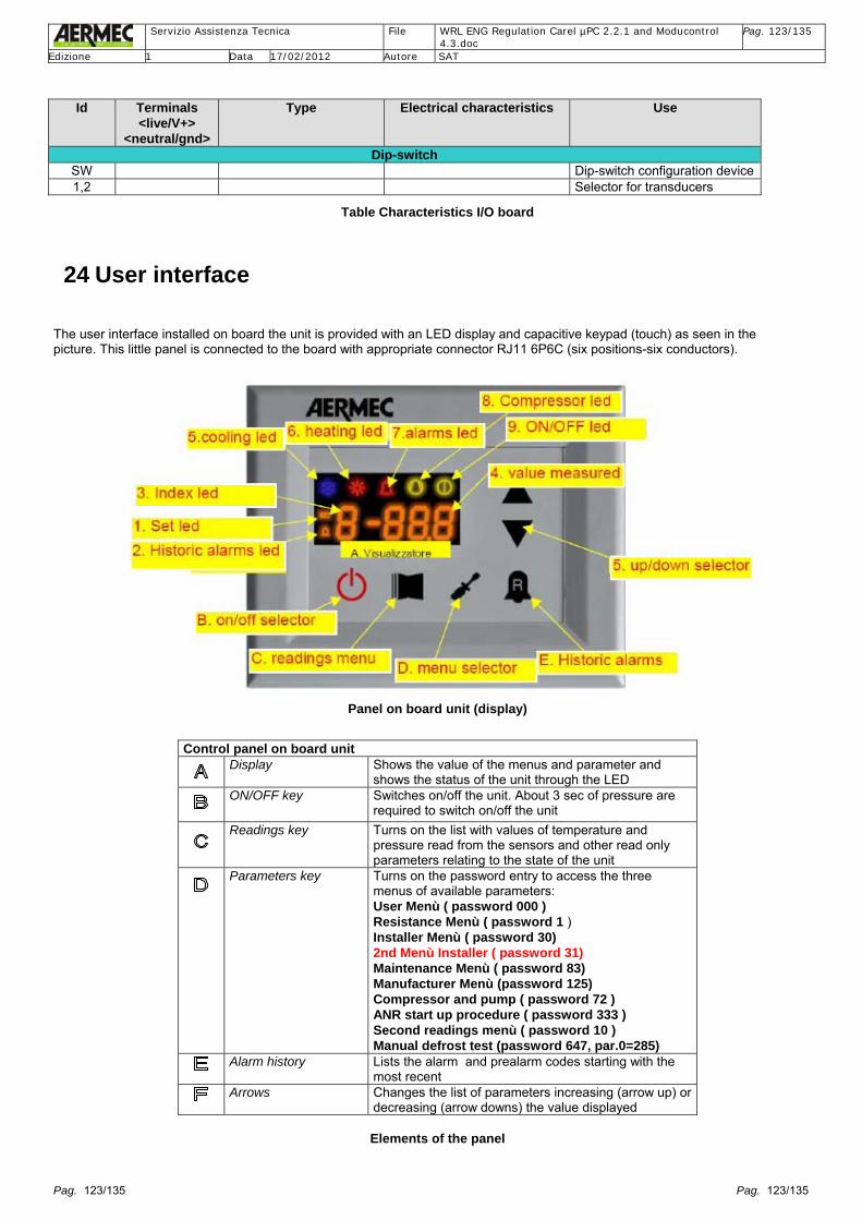
Servizio Assistenza Tecnica File WRL ENG Regulation Carel µPC 2.2.1 and Moducontrol
4.3.doc Pag. 123/135
Edizione 1 Data 17/02/2012 Autore SAT
Pag. 123/135 Pag. 123/135
Id Terminals
<live/V+> <neutral/gnd>
Type Electrical characteristics Use
Dip-switch SW Dip-switch configuration device1,2 Selector for transducers
Table Characteristics I/O board
24 User interface The user interface installed on board the unit is provided with an LED display and capacitive keypad (touch) as seen in the picture. This little panel is connected to the board with appropriate connector RJ11 6P6C (six positions-six conductors).
Panel on board unit (display)
Control panel on board unit
Display Shows the value of the menus and parameter and shows the status of the unit through the LED
ON/OFF key Switches on/off the unit. About 3 sec of pressure are required to switch on/off the unit
Readings key Turns on the list with values of temperature and pressure read from the sensors and other read only parameters relating to the state of the unit
Parameters key Turns on the password entry to access the three menus of available parameters: User Menù ( password 000 ) Resistance Menù ( password 1 ) Installer Menù ( password 30) 2nd Menù Installer ( password 31) Maintenance Menù ( password 83) Manufacturer Menù (password 125) Compressor and pump ( password 72 ) ANR start up procedure ( password 333 ) Second readings menù ( password 10 ) Manual defrost test (password 647, par.0=285)
Alarm history Lists the alarm and prealarm codes starting with the most recent
Arrows Changes the list of parameters increasing (arrow up) or decreasing (arrow downs) the value displayed
Elements of the panel

Servizio Assistenza Tecnica File WRL ENG Regulation Carel µPC 2.2.1 and Moducontrol
4.3.doc Pag. 124/135
Edizione 1 Data 17/02/2012 Autore SAT
Pag. 124/135 Pag. 124/135
Display LED set The LED set fixed indicates the values seen relative to
Menu set user (par. Errore. L'origine riferimento non è stata trovata.) or heater. The LED set flashing indicates the values seen in the Menu set assistance. The LED set fixed + LED alarm history flashing indicates seeing the Menu set factory or compressor.
LED alarm history LED alarm history fixed indicates seeing the alarm history. LED alarm history flashing indicates that the algorithm for low water content is active and that the compressor is held in standby for this reason. Indicates additionally that the CP is maintained off due to exceeding the operating limits of ForceOff dynamic. If LED alarm history and set are off means seeing the menu readings.
Index menu Identifies the parameter displayed within the menu indicated by the LED set.
Field Value Shows the value of the parameter, the maximum display of numbers is one decimal and two whole integers or three whole integers.
LED ‘cold’ LED cold fixed indicates that the unit is set by user parameter to produce chilled water and that the season contact is open. LED cold flashing indicates that the unit, even in standby, is functioning in frost protection mode turning on the circulator and eventually the anti-freeze heater. LED cold flashing + LED hot fixed defrost or part load injection in operation
LED ‘hot’ LED hot fixed indicates that the unit has parameter selected (or the season contact is closed) to produce hot water.
LED alarm LED alarm fixed the unit has tripped by an alarm. It has to be turned off and on manually. LED alarm flashing the unit is in prealarm and the compressor has been switched off. The unit will reset when the alarm clears (see paragraph, alarms)
LED compressor LED compressor fixed the compressor is on. LED compressor short flashes the compressor is awaiting the minimum stop timer (or timer between starts) before starting. LED compressor on short off flashes the compressor is on and awaiting the minimum run timer before stopping (see paragraph Control logic for the compressor)
LED ON/OFF LED ON/OFF on the unit is enabled to produce cold or hot water.
Elements of the display

Servizio Assistenza Tecnica File WRL ENG Regulation Carel µPC 2.2.1 and Moducontrol
4.3.doc Pag. 125/135
Edizione 1 Data 17/02/2012 Autore SAT
Pag. 125/135 Pag. 125/135
25 Menu readings This menu is accessed pressing the reading key (item C of the display in the preceding picture). The parameters for heat pump are shown shadowed, they are in blue for parameters visible with the DCP installed, in green for the readings relating to the configuration of twin compressor), whilst in yellow the readings relating to the inverter application. The parameters concerning the WRL units are highlighted. After 2’ the display returns to these screens from whichever display it was before.
N Code Name Description
Outlet water temperature Temperature (in °C) read by the sensor SUW NTC 10k in the outlet of the evaporator
Inlet water temperature Temperature (in °C) read by the sensor SIW NTC 10k in the inlet of the evaporator
Condenser coil temperature
Temperature (in °C) read by the sensor SS NTC 10k condensing in the condenser coil.
(WRL ONLY) seen as tic (temperature inlet condenser.
Discharge refrigerant temperature
Temperature (in °C) read by sensor SGP NTC 3.3k on the discharge
External air temperature Temperature (in °C) read by the sensor SAE NTC 10k
Discharge pressure Pressure in bar read by the transducer in compressor discharge
Suction pressure Pressure in bar read by the transducer of compressor suction pressure
(WRL ONLY) seen as tuC (temperature outlet condenser.
Thermostat Displays the percentage capacity requested by the thermostat based on the proportional/integral algorithm
Force-off safety range If the algorithm for low water content control is active this parameter indicates the temperature limit for the compressor restart
Timers cp Compressor timers. This display shows the time until start or stop of the compressor
Run hours (thousands) This display shows the run hours of the primary compressor (in thousands)
Run hours (unit) This display shows the run hours of the primary compressor
Starts (thousands) This display shows the number of compressor starts (in thousands)
Starts This display shows the number of compressor starts
Release This display shows the software version
Build Sub-version. This digit increases following release of versions that correct small errors or effect small improvements but do not change the main control function
Actual set Displays the actual set of the unit when operating: includes any corrections for ambient temperature (if function is active)

Servizio Assistenza Tecnica File WRL ENG Regulation Carel µPC 2.2.1 and Moducontrol
4.3.doc Pag. 126/135
Edizione 1 Data 17/02/2012 Autore SAT
Pag. 126/135 Pag. 126/135
N Code Name Description
Set DCP Pressure set used for condensing control
Range DCP Differential pressure used for condensing control
Run hour auxiliary compressor (thousands)
This display shows the run hours of the auxiliary compressor (in thousands)
Run hours auxiliary compressor (unit)
This display shows the run hours of the auxiliary compressor
Starts auxiliary cp (thousands)
This display shows the number of auxiliary compressor starts (in thousands)
Starts auxiliary compressor (unit)
This display shows the number of auxiliary compressor starts
Fraction of capacity Fraction of capacity: this reading indicates how much capacity is being provided by the unit. If the unit is configured as inverter this reading shows the frequency in use
Frequency requested to inverter
If the board is configured for inverter control this reading returns the frequency requested to the inverter board
Drop of pressure If the board is configured as heat pump this reading returns the drop of compressor suction pressure
Table of Readings (data cannot be modified)
26 Menu set user (password 000) The list of parameters is accessed pressing the parameters key (item D of the display shown in the previous picture) and inserting the password 000 (already displayed so only necessary to confirm) and confirming again with the parameters key. The parameters for heat pump are shown shadowed and are not shown in the cooling only models. As follows the parameters of this menu will be indicated as set_user(<digit parameter>).
N Code Name Min Default Max Description
Season 0 0 1 If 0 the unit operates in cooling mode unless the
operating mode is forced by contact. If 1 operates in heating mode. Changing this parameter with the unit running it will be automatically stopped and restarted with selected operating mode.
Set cold (°C) -20.0 7.0 26.0 Temperature Set used in cooling mode
Range cold (°C)
1.0 5.0 20.0 Temperature range used in cooling mode
Set Hot (°C) 25.0 45.0 Par(t)
menu PSW=30 *
Temperature Set used in heating mode *The maximum limit is configurable through parameter(t) in the menu with PSW=30 The maximum limit becomes 70° if the parameter(8) =4 to give the possibility to insert setpoint for the control of the boiler

Servizio Assistenza Tecnica File WRL ENG Regulation Carel µPC 2.2.1 and Moducontrol
4.3.doc Pag. 127/135
Edizione 1 Data 17/02/2012 Autore SAT
Pag. 127/135 Pag. 127/135
N Code Name Min Default Max Description
Range in hot (°C)
1.0 5.0 20.0 Temperature range used in heating mode
Correction Set 0 0 3 Parameter that indicates the activation of set
correction based on outdoor temperature: 0 – no correction on set 1 – correction on set in cooling mode 2 – correction on set in heating mode 3 – correction on set in heating and cooling mode
Set cool 1 (°C) -20.0 12.0 26.0 Visible only with correction set active. Set cool 1
corresponds to the temperature of parameter 7
Temperature outdoor air in cool1 (°C)
-40.0 18.0 50.0 Visible only with correction set active. Temperature outdoor air 1 which corresponds to the set in cool 1 parameter 6
Set in cool 2 (°C)
-20.0 7.0 26.0 Visible only with correction set active. Set in cool 2 corresponds to the temperature of parameter 9
Temperature outdoor air in cool 2 (°C)
-40.0 30.0 50.0 Visible only with correction set active. Temperature outdoor air 2 which corresponds to the set in cool 2 parameter 8
Set in heat 1 (°C)
15.0 45.0 Par(t) menu PSW=30 *
Visible only with correction set active. Set in heat 1. Set in heat used as first extreme between which the set is varied. *The maximum limit is configurable through parameter(t) in the menu with PSW=30 The maximum limit becomes 70° if the parameter(8) =4 to give the possibility to insert setpoint for the control of the boiler
Temperature outdoor air in heat 1 (°C)
-40.0 0 50.0 Visible only with correction set active. Temperature outdoor air which corresponds to the set in heat 1 (parameter A)
Set in heat 2 (°C)
15.0 35.0 Par(t) menu PSW=30 *
Visible only with correction set active. Set in heat 2. Set in heat used as second extreme between which the set is varied. *The maximum limit is configurable through parameter(t) in the menu with PSW=30 The maximum limit becomes 70° if the parameter(8) =4 to give the possibility to insert setpoint for the control of the boiler
Temperature outdoor air in heat 2 (°C)
-40.0 18.0 50.0 Visible only with correction set active. Temperature outdoor air which corresponds to the set in heat 2 (parameter C)
Set DHW (°C) 25.0 50.0 Par(t)
menu PSW=30 *
Temperature of set used when DHW production is activated. *The maximum limit is configurable through parameter(t) in the menu with PSW=30 The maximum limit becomes 70° if the parameter(8) =4 to give the possibility to insert setpoint for the control of the boiler
Range DHW (°C)
1.0 10.0 20.0 Temperature range used with the set in DHW mode
Table Set user

Servizio Assistenza Tecnica File WRL ENG Regulation Carel µPC 2.2.1 and Moducontrol
4.3.doc Pag. 128/135
Edizione 1 Data 17/02/2012 Autore SAT
Pag. 128/135 Pag. 128/135
Important: compensation in cooling If the external ambient KSAE sensor is installed the unit’s compensation in cooling is available, see Menu set user, parameter 5 CSt (Correction setpoint) inserting 1 (Correction setpoint in cool), and as a consequence it will be possible to see and modify the following parameters: - 6 SFI (Set cool 1 value in °C), - 7 tFI (Temperature outdoor air referred to the Set cool 1, value in °C) - 8 SF2 (Set cool 2 value in °C), - 9 tF2 (Temperature outdoor air referred to the Set cool 2, value in °C)

Servizio Assistenza Tecnica File WRL ENG Regulation Carel µPC 2.2.1 and Moducontrol
4.3.doc Pag. 129/135
Edizione 1 Data 17/02/2012 Autore SAT
Pag. 129/135 Pag. 129/135
27 Menu customer (password 030) The list of parameters is accessed pressing the parameters key (item D del of the display in the preceding picture) and inserting the indicated password, using the arrows and confirming again with the parameters key. To modify the set anti-freeze in the case of unit version Y
N Code Name Min Default Max Description
Anti-freeze (°C) -50.0 3.0 20.0 Anti-freeze limit can be modified only from dip-
switch settings. If the dip-switch is OFF the default value is used
To configure PR3 remote panel
N Code Name Min Default Max Description
Config panel 0 0 3 0 – season (MODE COOL/HEAT) decided from
parameter 0, control ON/OFF set by panel on board unit, 1 – control ON/OFF from remote contact, season decided by parameter 0, 2 – control ON/OFF by panel on board unit, season decided by contact, 3 - control ON/OFF from remote contact, season decided by remote. The remote panel if enabled has priority over controls sent by a BMS supervisor
To configure ModBus address in the case of installation of MODU-485° accessory
N Code Name Min Default Max Description
J Ad1 Address ModBus Supervisor
1 1 999 ModBus address that the supervisor has to use to communicate with moducontrol Insert 200
L Bd1 Baud rate Supervisor
0 1 2 Baud rate that the supervisor has to use to communicate with moducontrol. (8bit data, N-parity, 2 stop bits) 0 – 9600 bps 1 – 19200 bps 2 – 38400 bps
n AS1 Enable supervisor writing
0 0 1 0 – Disables write commands 1 – Enables write commands The read commands are always enabled. If the remote panel is enabled this has priority. See paragraph(9).
28 Menu configuration compressor and pump (password 072) The list of parameters is accessed pressing the parameters key (item D del of the display in the preceding picture) and inserting the indicated password, using the arrows and confirming again with the parameters key. N Code Name Min Default Max Description
Percentage capacity of auxiliary compressor (%)
0 0 80 This parameter set to zero means the unit has one compressor. If this parameter is entered with a value greater than zero the unit is tandem and the value indicates the percentage capacity associated with the auxiliary compressor controlled from output CPA. Parameter to be considered for WRL units sizes WRL sizes 100, 140 and 160 twin compressor.

Servizio Assistenza Tecnica File WRL ENG Regulation Carel µPC 2.2.1 and Moducontrol
4.3.doc Pag. 130/135
Edizione 1 Data 17/02/2012 Autore SAT
Pag. 130/135 Pag. 130/135
N Code Name Min Default Max Description
Minimum run time cp (sec)
20 120 900 Minimum compressor run time. Valid for both compressors
Minimum off time cp (sec)
20 180 900 Minimum compressor off time
Starts per hour 3 12 30 Number of starts per hour
Interval between two compressor starts (sec)
10 30 600 Time interval needed between the start of two compressors in tandem configuration. This parameter is forced to the value of parameter 1 when the low water content function is selected
Interval of pump operation from first start to stabilise sensors (sec)
30 150 600 The first time that the unit is started after powering up the pump operates for a particularly long time if the control load is activated to allow stabilisation of the water sensors.
Flow switch filter with pump operating (sec)
2 5 120 Minimum time for a flow switch trip with pump operating to be considered by the board. See Flow switch/pressostat differential (fl/pd)
Flow switch filter with pump starting (sec)
2 40 360 At pump start the flow switch is ignored for a time interval equal to this value. See Flow switch/pressostat differential (fl/pd)
Pause pump (sec) 10 120 999 Time to stop pump after intervention of the
flow switch / pressostat differential. See Flow switch/pressostat differential (fl/pd)
Pulldown (°C) 0.0 1.0 10.0 If during the operation in heating or cooling
the water temperature varies in one minute by a value equal or greater than the quantity indicated in the parameter (positive if in heating, negative if in heating). The start of the second compressor is inhibited even if requested
Minimum time off CP even in IC (sec)
0 0
600 When parameter 2 replaced by different than zero. Unlike parameter 2 this time is respected even exiting the reversing cycle. Parameter to be used in case soft-start present
29 Menu service (password 083) The list of parameters is accessed pressing the parameters key (item D del of the display in the preceding picture) and inserting the indicated password, using the arrows and confirming again with the parameters key. N Name Min Default Max Description
TAE minimum DCP (°C)
-20.0 -5.0 32.0 Minimum temperature used for the calculation of the condensing set
TAE maximum DCP (°C)
34.0 40.0 45.0 Maximum temperature used for the calculation of the condensing set
P set minimum (bar)
5.0 18.0 (12 ANR)
24.0 Minimum pressure set used for the calculation of the condensing set
P set maximum (bar)
5.0 18.0 (12 ANR)
38.0 Maximum pressure set used for the calculation of the condensing set
P range T min (bar)
2.0 17.0 (14 ANR)
20.0 Range of the minimum outdoor temperature for the control of the condensing set

Servizio Assistenza Tecnica File WRL ENG Regulation Carel µPC 2.2.1 and Moducontrol
4.3.doc Pag. 131/135
Edizione 1 Data 17/02/2012 Autore SAT
Pag. 131/135 Pag. 131/135
N Name Min Default Max Description
P range T max (bar)
2.0 12.0 (8 ANR)
20.0 Range of the maximum outdoor temperature for the control of the condensing set
Minimum voltage output from DCP
0.1 1.5 9.0 Minimum voltage (corresponding to the minimum velocity) output from DCP
Important: for the WRL unit, with or without external air temperature sensor present, the board always uses as setpoint the condensing pressure parameter J and range of pressure the parameter N. The condensing control through the pressure of condensation read by the high pressure transducer generates a change of voltage 0-10 Volt DC to supply a modulating valve or geothermal (condenser) pump inverter; the parameters affected are seen in Menu assistance password 083: - J, P set minimum (bar), Minimum pressure set used for the calculation of the condensing set, - n, P range T min (bar), Range of the minimum outdoor temperature for the control of the condensing set,

Servizio Assistenza Tecnica File WRL ENG Regulation Carel µPC 2.2.1 and Moducontrol
4.3.doc Pag. 132/135
Edizione 1 Data 17/02/2012 Autore SAT
Pag. 132/135 Pag. 132/135
30 Configuration micro-switches (dip-switch) As well as the panel parameters the board has 12 + 2 micro-switches that allow some configurations relating to the unit that the board is mounted on. The micro-switches are read at the moment the board is powered (if they are to be modified the board has to be powered down). # Default Description 1 - OFF – unit cool only (no transducers provided the absence of DCP, reversing valve…)
ON – unit heat pump 2 OFF OFF – defrost by hot gas injection
ON – defrost exclusively by reversing cycle 3 OFF OFF – set anti-freeze (set_installer(6)) fixed
ON – water glycol mix: set anti-freeze adjustable 4 OFF OFF – control load enabled
ON – control load disabled 5 OFF OFF – part load for safety enabled
ON – part load for safety disabled (with inverter not disabled) 6 OFF OFF – algorithm to control low water content enabled
ON – algorithm to control low water content disabled 7 OFF OFF – device to control condensing pressure absent
ON – device to control condensing pressure present 8 OFF OFF – Configured for ANL (unit with R410a)
ON – Configured for ANR / ANF (unit with R407c) This dip’s only function is the selection between two predefined set of default parameters when are used when on the unit a parameter reset is effected
9 OFF OFF – Configured for normal chiller ON/OFF ON – Configured for unit with inverter
10 OFF OFF – Chiller ON – Condensing unit
11 OFF ON = WRL only cooling (water/water) OFF = chiller water/air
12 OFF Not used
Table meaning 12 micro-switches (dip-switch)
1 OFF OFF – The low pressure transducer is of ratiometric Type (provides a voltage signal between 0.5 V and 4.5 V) ON – The low pressure transducer is of piezoelectric Type (provides a current signal between 4 mA and 20 mA)
2 OFF OFF – The high pressure transducer is of ratiometric Type (provides a voltage signal between 0.5 V and 4.5 V) ON – The high pressure transducer is of piezoelectric Type (provides a current signal between 4 mA and 20 mA)
Table meaning dip-switch transducers

Servizio Assistenza Tecnica File WRL ENG Regulation Carel µPC 2.2.1 and Moducontrol
4.3.doc Pag. 133/135
Edizione 1 Data 17/02/2012 Autore SAT
Pag. 133/135 Pag. 133/135
31 Setting up software version SW 4.3.0
31.1 Configuration parameters of the Software In relation to the different versions and accessories available for correct operation it is necessary to check that all the configuration parameters of the software are correct. To make this operation quicker the procedure checks and modifies only the parameters that are different from the standard version already loaded.
31.2 Dip-switch configuration of the board The configuration of the dips must be carried out as the first set-up procedure with board not powered up.
1. ENSURE THAT ALL THE DIP ARE IN THE OFF POSITION. 2. Position in ON only the dip that correspond to the unit represented below
DIP Model Description
1 H OFF – Unit cool only
2 OFF 3 Y,Z ON – water glycol mix: set anti-freeze adjustable
4 OFF
5 All ON – part load for safety disabled
6 OFF
7 DCPX OFF ON – device to control condensing pressure present (bore hole/geothermal pump inverter or modulating valve)
8 OFF
9 OFF
10 OFF
11 WRL Cool only ON – Unit water/water cool only
12 Not used
BEFORE PERFORMING THE SOFTWARE SETTING-UP PROCEDURE LOAD THE DEFAULT PARAMETERS: Set to 1 the parameter(0) of the menu factory (Password 125). The parameter turns to zero when the default parameters are loaded. Some parameters are found in different locations depending on the version of software loaded. Check the software version through parameter(E) and parameter(F) in the menu readings. Example: parameter(E) = 3.6 and parameter(F) = 3 version software loaded = 3.6.3

Servizio Assistenza Tecnica File WRL ENG Regulation Carel µPC 2.2.1 and Moducontrol
4.3.doc Pag. 134/135
Edizione 1 Data 17/02/2012 Autore SAT
Pag. 134/135 Pag. 134/135
t

Servizio Assistenza Tecnica File WRL ENG Regulation Carel µPC 2.2.1 and Moducontrol
4.3.doc Pag. 135/135
Edizione 1 Data 17/02/2012 Autore SAT
Pag. 135/135 Pag. 135/135


