Engine Turbo/Super Charging
Super and Turbo-charging
Why super/ turbo-charging?
• Fuel burned per cycle in an IC engine is air limited – (F/A)stoich = 1/14.6
f,v– fuel conversion and volumetric efficiencies m Qf f HV mf – fuel mass per cycle Torq QHV– fuel heating value
2n nR – 1 for 2-stroke, 2 for 4-stroke engine R N – revolution per second – engine displacement Power Torq 2N VD
a,0 – air density
Fm Va,0VDf A
Super/turbo-charging: increase air density
1
Super- and Turbo- Charging
Purpose: To increase the charge density • Supercharge: compressor powered by engine output
– No turbo-lag – Does not impact exhaust treatment – Less efficient than turbo-charging
• Turbo-charge: compressor powered by exhaust turbine – More directly utilize exhaust energy – Turbo- lag problem – Affects exhaust treatment
• Intercooler – Increase charge density (hence output power) by cooling the
charge – Lowers NOx emissions – Suppresses knock
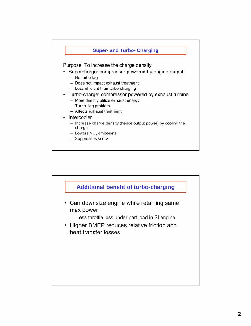
Additional benefit of turbo-charging
• Can downsize engine while retaining same max power – Less throttle loss under part load in SI engine
• Higher BMEP reduces relative friction and heat transfer losses
2
Engine Losses 12
11 Spark retard/enrichment for SI; 5th gear, smoke limit for diesel flat road
10
9 4th gear, flat road
Relative 8 efficiency = 1
Heat transfer Combustion speed, pumping loss 7
6
252 5 g/KW-hr
Th
rott
le +
ht
tran
sf +
fri
ctio
n
BM
EP
(b
ar)
=0.88
=0.78 =0.70 4 288 =0.64
3rd gear, 3
324 =0.58 flat road
360 =0.54 2 =0.50
1 1000 2000 3000 4000 5000
5 Engine speed (rpm) Data from SAE 910676; Saturn I4 engine
© Society of Automotive Engineers. All rights reserved. This content is excluded from our Creative Commons license. For more information, see https://ocw.mit.edu/help/faq-fair-use.
SI engine efficiency opportunity
Turbo DISI as enabling technology
– Fuel in-flight evaporation 12 cools charge
Regain load More knock 10 head room by resistant
8 turbo-charging
BM
EP
(bar
)
6
4
2 – Cold start emissions
Taurus FTP 0 sec-by-sec HC
-2 PM 0 1000 2000 3000
Speed (rpm)
IssuesShift op.
Knock points up by – downsizing – Peak pressure
– Boosting capacity
3
Exhaust-gas turbocharger for trucks 1.Compressor housing, 2. Compressor impeller, 3. Turbine housing, 4. Rotor, 5. Bearing housing, 6. inflowing exhaust gas, 7. Out-flowing exhaust gas, 8. Atmospheric fresh Charge-air pressure regulation with air, 9. Pre-compressed fresh air, 10. Oil inlet, wastegate on exhaust gas end. 1.Engine, 11. Oil return 2. Exhaust-gas turbochager, 3. Wastegate
From Bosch Automotive Handbook
© Robert Bosch GmbH. All rights reserved. This content is excluded from our Creative Commons license. For more information, see https://ocw.mit.edu/help/faq-fair-use.
Turbo-charger
Source: BorgWarner Turbo Systems
Waste gate
© BorgWarner Turbo Systems. All rights reserved. This content is excluded from our Creative Commons license. For more information, see https://ocw.mit.edu/help/faq-fair-use.
4
Variable geometry turbo-charger
Variable Guide Vane Variable sliding ring
Source: BorgWarner Turbo Systems
© BorgWarner Turbo Systems. All rights reserved. This content is excluded from our Creative Commons license. For more information, see https://ocw.mit.edu/help/faq-fair-use.
Compressor: basic thermodynamics
1
2
m
Compressor efficiency c
W idealW c Wactual
T 2 W m c T 1ideal p 1T T1
1T P 2 2 T P1 1
1 1 P
W actual m cpT1 2 1
c P1
Wactuals T T 2 1 m cp
P1
P2
1
2’ 2
Ideal process
Actual process
5
Turbine: basic thermodynamics Turbine efficiency t4
WW actual t W ideal 3 m T 4 W m c T 1ideal p 3 T3 T
1T P 4 4 T P3 3
1 P
W actual tm cpT3 1 4
P3
WactualT T s 4 3 m cp
• Power transfer between fluid and shaft RPM3
– Typically operate at ~ 60K to 120K RPM
• RPM limited by centrifugal stress: usually tip velocity is approximately sonic
• RPM also limited by shock waves
• Flow devices, sensitive to boundary layer (BL) behavior – Compressor: BL under unfavorable gradient – Turbine: BL under favorable gradient
6
P4
P3
4’
3
4
Ideal process
Actual process
Properties of Turbochargers
Torque characteristics of flow machinery
Angular momentum theorem
Torq rV V dA rV V dA x x 1 2
VxV
both V and V are fixed by the blade angle x
so that both are RPM, therefore: Vx 1
Torq RPM 2 V
Power RPM3
V
Vx
2
Rotor stress
Force balance over mass element from r to dr Cross-section2r area A A A Adrr rdr m r dr
or d A 2 mA r
dr To illustrate effect, say A is independent of r, then :
2 Max at m 2 2 root
2 t
Rt
Rroot
(r) R r
r
Tensile stress m Material density Angular velocity = 2N
rRt Tip radius
7
Typical super/turbo-charged engine parameters
• Peak compressor pressure ratio 2.5
• BMEP up to 24 bar • Limits:
– compressor aerodynamics
– cylinder peak pressure
– NOx emissions
Compressor/Turbine Characteristics
• Delivered pressure P2
• P2 = f( m ,RT1,P1,N,D,, , geometric ratios) • Dimensional analysis:
– 7 dimensional variables (7-3) = 4 dimensionless parameters (plus and geometric ratios)
P N m 2 f( , ,Re, , geometric ratios)
P RT / D P RT D 1 1 1 12
RT1 Velocity Velocity
Density
High Re number flow weak Re dependence
For fixed geometry machinery and gas properties
P2 N m T 1
f , P T P 1 1 1
8
Compressor Map
Pre
ssur
e ra
tio
1
“Corrected” Flow rate m T1/P1
T1= inlet temperature (K); P1= inlet pressure (bar); N = rev. per min.; m = mass flow rate (kg/s) (From “Principles and Performance in Diesel Engineering,” Ed. by Haddad and Watson)
Compressor stall and surge
• Stall – Happens when incident flow angle is too large
(large V/Vx) – Stall causes flow blockage
• Surge – Flow inertia/resistance, and compression system
internal volume comprise a LRC resonance system – Oscillatory flow behave when flow blockage occurs
because of compressor stall reverse flow and violent flow rate surges
9
Turbine Map
Mass flow
Efficiency
Source: BorgWarner Turbo Systems
© BorgWarner Turbo Systems. All rights reserved. This content is excluded from our Creative Commons license. For more information, see https://ocw.mit.edu/help/faq-fair-use.
Compressor Turbine Matching Exercise
• For simplicity, take away intercooler and wastegate
• Given engine brake power 1 4 output ( ) and RPM, WE
compressor map, turbine map, and engine map
• Find operating point, i.e. air flow ( ), fuel flow rate ( )mf
ma
turbo-shaft revolution per second (N), compressor and turbine pressure ratios (c and
mf
t) etc.
WE
Diesel Engine
C T
QL
2 3
10
Compressor/ turbine/engine matching
solution
1
c
1 2 c 1 2 c 1
c
a
Procedure: 1. Guess ; can get engine inlet conditions:
TP P T 1 T
2. Then engine volumetric efficiency calibration
will give the air flow m that can be '
a c
f
E f f E
swallowed' 3. From m and , the compressor speed N can be
obtained from the compressor map
4. The fuel flow rate m may be obtained from the
engine map: W m LHV (RPM,W ,A/F)
5. Eng
3
M
E a f p 3 a p 2 f L
M
t t
ine exhaust temperature T may be obtained from
energy balance (with known engine mech. eff. )
W(m m )c T m c T m LHV Q
6. Guess , then get turbine speed N from turbine map
and
1
t t t
c t t c t c
mass flow
7. Determine turbine power from turbine efficiency on map
1W 1
8. Iterate on the values of and until W W and N N
Flow rate T/P m
Pre
ssur
e ra
tio
Compressor
Inter-Cooler
Engine
C T
Wastegate
Compressor/ Engine/ Turbine Matching
• Mass flows through compressor, engine, turbine and wastegate have to be consistent
• Turbine inlet temperature consistent with fuel flow and engine power output
• Turbine supplies compressor work
• Turbine and compressor at same speed
Compressor characteristics, with airflow requirements of a four-stroke truck engine superimposed. (From “Principles and Performance in Diesel Engineering,” Ed. by Haddad and Watson)
© BorgWarner Turbo Systems. All rights reserved. This content is excluded from our Creative Commons license. For more information, see https://ocw.mit.edu/help/faq-fair-use.
© Ellis Horwood Ltd. All rights reserved. This content is excluded from our Creative Commons license. For more information, see https://ocw.mit.edu/help/faq-fair-use.
11
Advanced turbocharger development
Electric assisted turbo-charging
• Concept – Put motor/ generator on
turbo-charger – reduce wastegate function
• Benefit – increase air flow at low
engine speed – auxiliary electrical output
at part load
Motor/ Generator
Inter-Cooler
Engine
C T
Wastegate
Battery
Advanced turbocharger development
Electrical turbo-charger • Concept
– turbine drives generator; compressor driven by motor
• Benefit – decoupling of turbine and
compressor map, hence much more freedom in performance optimization
– Auxiliary power output – do not need wastegate; no turbo-lag
Generator
Inter-Cooler
Engine
C TMotor
Battery
12
Advanced turbocharger development
Challenges
• Interaction of turbo-charging system with exhaust treatment and emissions – Especially severe in light-duty diesel market
because of low exhaust temperature
– Low pressure and high pressure EGR circuits
Transient response
• Cost
EGR/ turbo Configurations
From SAE 2007-01-2978
© Society of Automotive Engineers. All rights reserved. This content is excluded from our Creative Commons license. For more information, see https://ocw.mit.edu/help/faq-fair-use.
13
Hybrid EGR
From SAE 2009-01-1451
© Society of Automotive Engineers. All rights reserved. This content is excluded from our Creative Commons license. For more information, see https://ocw.mit.edu/help/faq-fair-use.
Two stage turbo with HP EGR loop
SAE 2008-01-0611
© Society of Automotive Engineers. All rights reserved. This content is excluded from our Creative Commons license. For more information, see https://ocw.mit.edu/help/faq-fair-use.
14
MIT OpenCourseWare https://ocw.mit.edu
2.61 Internal Combustion EnginesSpring 2017
For information about citing these materials or our Terms of Use, visit: https://ocw.mit.edu/terms.