November 2009 DS6.1 ENGINEERING DESIGN STANDARDS SECTION 6 - SANITARY SEWER DESIGN DS6-01. GENERAL: Sanitary sewer improvements shall be designed to serve the ultimate level of development as defined in the City General Plan. All improvements shall conform to the requirements of the Solano County Health Department, the Uniform Plumbing Code, and the City of Dixon Engineering Design Standards and Construction Specifications. DS6-02. PLAN REQUIREMENTS: Sanitary sewer improvement plans shall show geometric designs in both plan and profile views. Required information shall be main and lateral sizes and slopes, utility crossings, manholes, cleanouts, invert elevations, and any calculation used in the design of the system. DS6-03. DESIGN A. Flow - The design sanitary sewer flow in gallons per day (gpd) shall be calculated using the following formula: Q d = Q p + I & I , where Q d = Design flow Q p = Peak flow = Average Daily Flow x Peaking Factor I+ I = Infiltration & Inflow Factor The average daily flow rates and the I+I (Infiltration & Inflow) factors for various land uses are shown in the following table: DESIGN FLOWS LAND USE AVERAGE DAILY FLOW I+I FACTOR Single-Family 350 gpd per unit 500 gpd per gross acre Multi-Family 5000 gpd per net acre 500 gpd per gross acre Commercial/Public 1500 gpd per net acre 500 gpd per gross acre Industrial 2000 gpd per net acre 500 gpd per gross acre Schools 5000 gpd per net acre 500 gpd per gross acre *Note: Net Acres is assumed as 80% of Gross Acres.
Transcript
November 2009 DS6.1
ENGINEERING DESIGN STANDARDS
SECTION 6 - SANITARY SEWER DESIGN
DS6-01. GENERAL: Sanitary sewer improvements shall be designed to serve the ultimate level of development as defined in the City General Plan. All improvements shall conform to the requirements of the Solano County Health Department, the Uniform Plumbing Code, and the City of Dixon Engineering Design Standards and Construction Specifications.
DS6-02. PLAN REQUIREMENTS: Sanitary sewer improvement plans shall show geometric designs in both plan and profile views. Required information shall be main and lateral sizes and slopes, utility crossings, manholes, cleanouts, invert elevations, and any calculation used in the design of the system.
DS6-03. DESIGN
A. Flow - The design sanitary sewer flow in gallons per day (gpd) shall be calculated using the following formula:
Qd = Qp + I & I , where
Qd = Design flow Qp = Peak flow = Average Daily Flow x Peaking Factor I+ I = Infiltration & Inflow Factor
The average daily flow rates and the I+I (Infiltration & Inflow) factors for various land uses are shown in the following table:
DESIGN FLOWS
LAND USE AVERAGE DAILY FLOW I+I FACTOR
Single-Family 350 gpd per unit 500 gpd per gross acre
Multi-Family 5000 gpd per net acre 500 gpd per gross acre
Commercial/Public 1500 gpd per net acre 500 gpd per gross acre
Industrial 2000 gpd per net acre 500 gpd per gross acre
Schools 5000 gpd per net acre 500 gpd per gross acre *Note: Net Acres is assumed as 80% of Gross Acres.
November 2009 DS6.2
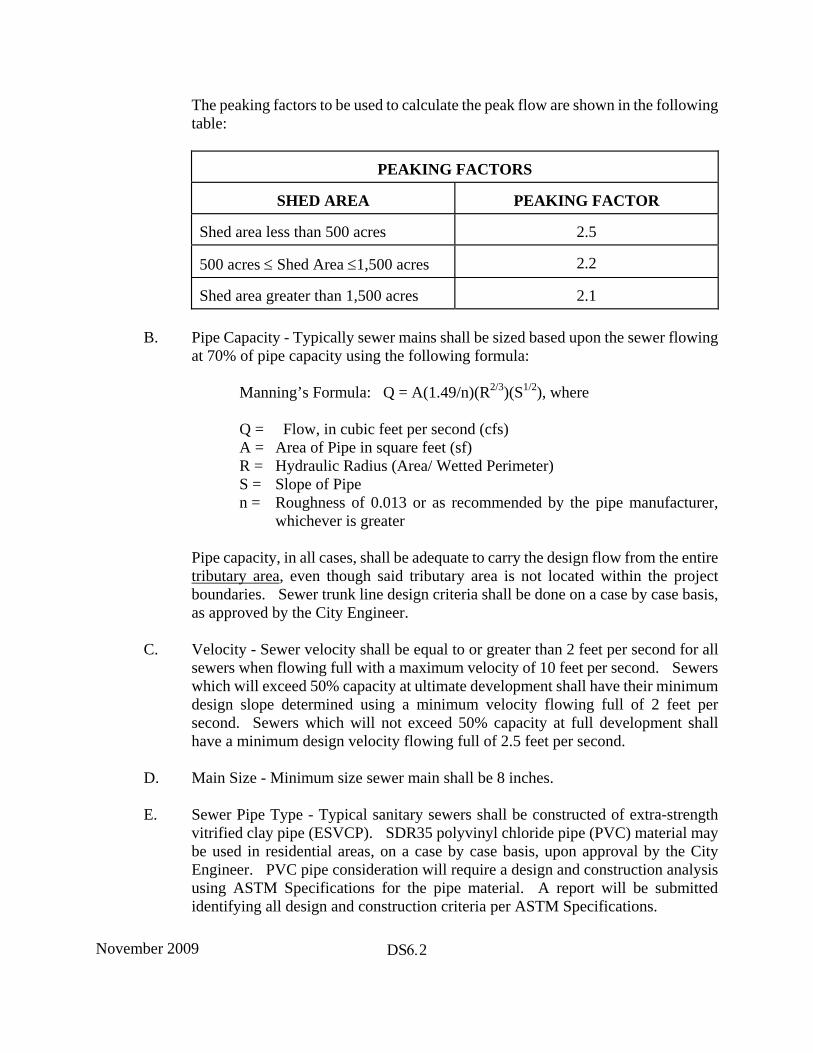
The peaking factors to be used to calculate the peak flow are shown in the following table:
PEAKING FACTORS
SHED AREA PEAKING FACTOR
Shed area less than 500 acres 2.5
500 acres ≤ Shed Area ≤1,500 acres 2.2
Shed area greater than 1,500 acres 2.1
B. Pipe Capacity - Typically sewer mains shall be sized based upon the sewer flowing at 70% of pipe capacity using the following formula:
Manning’s Formula: Q = A(1.49/n)(R2/3)(S1/2), where
Q = Flow, in cubic feet per second (cfs) A = Area of Pipe in square feet (sf) R = Hydraulic Radius (Area/ Wetted Perimeter) S = Slope of Pipe n = Roughness of 0.013 or as recommended by the pipe manufacturer,
whichever is greater
Pipe capacity, in all cases, shall be adequate to carry the design flow from the entire tributary area, even though said tributary area is not located within the project boundaries. Sewer trunk line design criteria shall be done on a case by case basis, as approved by the City Engineer.
C. Velocity - Sewer velocity shall be equal to or greater than 2 feet per second for all sewers when flowing full with a maximum velocity of 10 feet per second. Sewers which will exceed 50% capacity at ultimate development shall have their minimum design slope determined using a minimum velocity flowing full of 2 feet per second. Sewers which will not exceed 50% capacity at full development shall have a minimum design velocity flowing full of 2.5 feet per second.
D. Main Size - Minimum size sewer main shall be 8 inches.
E. Sewer Pipe Type - Typical sanitary sewers shall be constructed of extra-strength vitrified clay pipe (ESVCP). SDR35 polyvinyl chloride pipe (PVC) material may be used in residential areas, on a case by case basis, upon approval by the City Engineer. PVC pipe consideration will require a design and construction analysis using ASTM Specifications for the pipe material. A report will be submitted identifying all design and construction criteria per ASTM Specifications.
November 2009 DS6.3
F. STUDY MAP - A study map may be required prior to review of the sewer design if there is a possibility that upstream or adjacent areas might require service through the subject property. The map should show the entire service area including upstream tributary and adjacent areas, and all other data necessary to determine anticipated service area, including pipe sizes and slopes, shall be shown to the extent necessary to determine the requirements within the subject property. Any required study map shall be paid for by the project developer; however, said study map may be waived by the City Engineer if previously preformed.
DS6-04. VERTICAL ALIGNMENT
A. At all manholes where a change of direction of more than 20 degrees occurs, the flow line of the upstream main shall be 0.20 ft. above the flow line of the downstream main.
B. Where a change in size of mains occurs, the crowns shall be matched. C. No vertical curves shall be allowed. D. Where minor mains connect to trunk mains, the crowns shall match if feasible.
Under no circumstances shall the invert of the minor main enter the trunk main below springline.
DS6-05. HORIZONTAL ALIGNMENT
A. All sanitary sewers shall be installed in the pavement area of the street. Generally the location should be 6 feet from the center line of the street, on the opposite side of the centerline from the water line.
B. Under special circumstances, if approved in advance of plan submittal, exception may be granted by the City Engineer which will allow a sanitary sewer line to be placed in an easement. In such cases, a minimum 15 foot wide easement shall be given, and the easement shall cross not more than one lot. Deeper lines shall require a wider easement to the satisfaction of the City Engineer.
C. Location in existing streets - The following shall be considered: location of curbs, gutters, and sidewalks; traffic lane configurations; future street improvement plans; and existing utilities.
DS6-06. SEWER MAIN CLEARANCES: Clearances between sanitary sewer mains and other facilities shall conform to state law, but shall not be less than:
Horizontal: 10 feet minimum from any water line 5 feet minimum from all other facilities
Vertical: 1 foot minimum from all facilities for main lines 6" minimum from all facilities for service laterals
November 2009 DS6.4
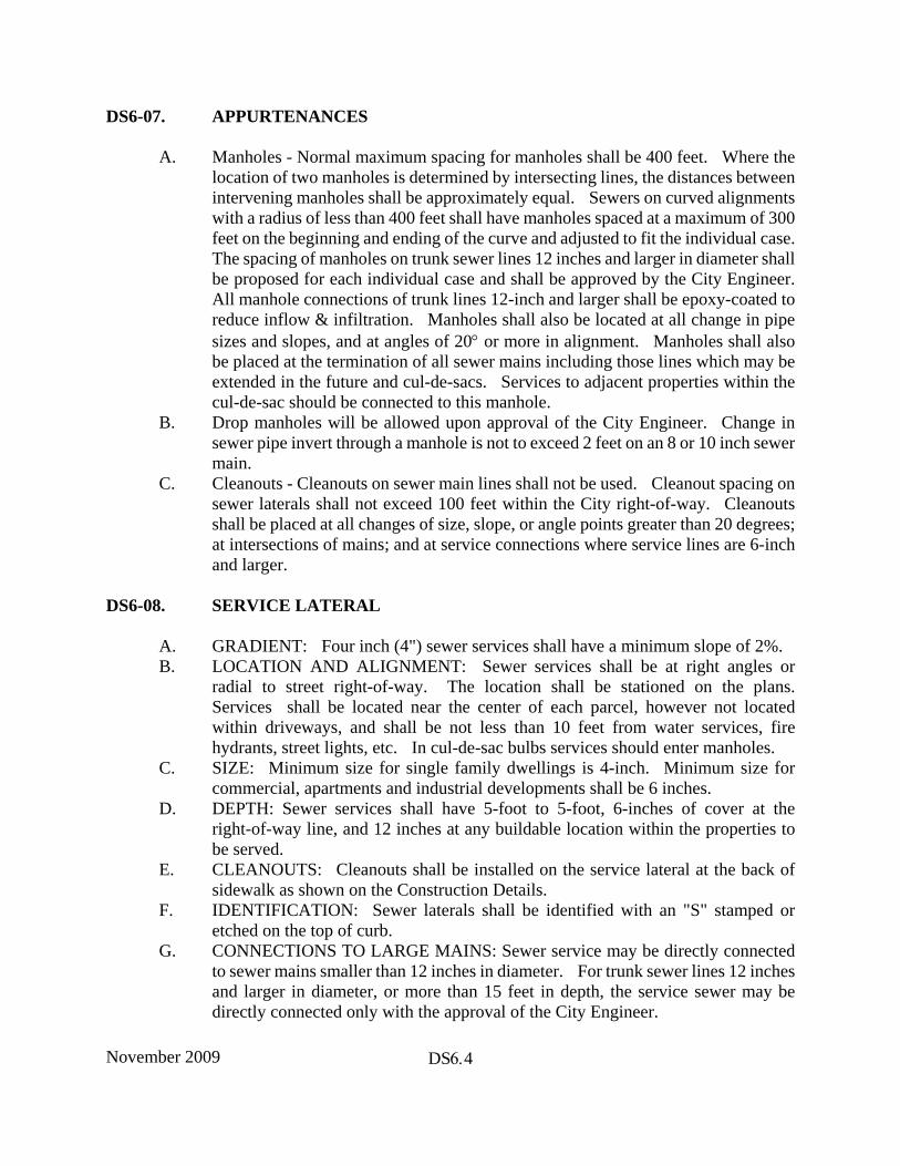
DS6-07. APPURTENANCES
A. Manholes - Normal maximum spacing for manholes shall be 400 feet. Where the location of two manholes is determined by intersecting lines, the distances between intervening manholes shall be approximately equal. Sewers on curved alignments with a radius of less than 400 feet shall have manholes spaced at a maximum of 300 feet on the beginning and ending of the curve and adjusted to fit the individual case. The spacing of manholes on trunk sewer lines 12 inches and larger in diameter shall be proposed for each individual case and shall be approved by the City Engineer. All manhole connections of trunk lines 12-inch and larger shall be epoxy-coated to reduce inflow & infiltration. Manholes shall also be located at all change in pipe sizes and slopes, and at angles of 20° or more in alignment. Manholes shall also be placed at the termination of all sewer mains including those lines which may be extended in the future and cul-de-sacs. Services to adjacent properties within the cul-de-sac should be connected to this manhole.
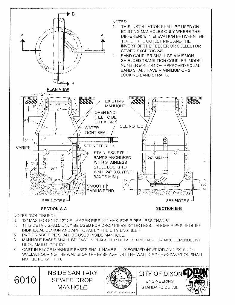
B. Drop manholes will be allowed upon approval of the City Engineer. Change in sewer pipe invert through a manhole is not to exceed 2 feet on an 8 or 10 inch sewer main.
C. Cleanouts - Cleanouts on sewer main lines shall not be used. Cleanout spacing on sewer laterals shall not exceed 100 feet within the City right-of-way. Cleanouts shall be placed at all changes of size, slope, or angle points greater than 20 degrees; at intersections of mains; and at service connections where service lines are 6-inch and larger.
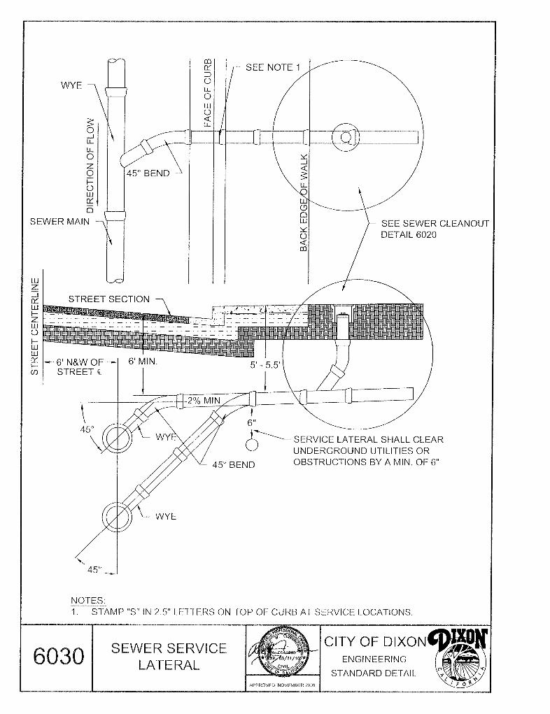
DS6-08. SERVICE LATERAL
A. GRADIENT: Four inch (4") sewer services shall have a minimum slope of 2%. B. LOCATION AND ALIGNMENT: Sewer services shall be at right angles or
radial to street right-of-way. The location shall be stationed on the plans. Services shall be located near the center of each parcel, however not located within driveways, and shall be not less than 10 feet from water services, fire hydrants, street lights, etc. In cul-de-sac bulbs services should enter manholes.
C. SIZE: Minimum size for single family dwellings is 4-inch. Minimum size for commercial, apartments and industrial developments shall be 6 inches.
D. DEPTH: Sewer services shall have 5-foot to 5-foot, 6-inches of cover at the right-of-way line, and 12 inches at any buildable location within the properties to be served.
E. CLEANOUTS: Cleanouts shall be installed on the service lateral at the back of sidewalk as shown on the Construction Details.
F. IDENTIFICATION: Sewer laterals shall be identified with an "S" stamped or etched on the top of curb.
G. CONNECTIONS TO LARGE MAINS: Sewer service may be directly connected to sewer mains smaller than 12 inches in diameter. For trunk sewer lines 12 inches and larger in diameter, or more than 15 feet in depth, the service sewer may be directly connected only with the approval of the City Engineer.
November 2009 DS6.5
H. TYPE OF PIPE: Same as sewer mains. Cleanout assemblies and service to site from the cleanout may be ABS per Construction Detail 6020.
I. ONSITE CONNECTIONS: Storm runoff shall not be designed to enter the sanitary sewer system.
J. Each parcel within commercial and industrial districts, including multi-family development service laterals, shall connect to a sewer main manhole unless approved otherwise by the City Engineer.
DS6-09. TRENCH LOADING: For sanitary sewer lines over 10 feet deep, Marston’s formula shall be used to determine the load placed on the pipe by backfill. The procedure for rigid pipe is described in the ASCE Manual of Engineering Practice No. 60, the Clay Pipe Engineering Manual, and in similar handbooks. The Design Engineer shall determine the factor of safety. Only the three edge bearing strength of the pipe shall be used in the computations for rigid pipe. The minimum trench width shall be O.D. plus 12 inches.
DS6-10. BEDDING AND INITIAL BACKFILL: Bedding types and factors for V.C.P. shall be as per Construction Details 3280 and 3290. For other materials, the trench width, bedding, and initial backfill shall be consistent with the pipe manufacturer’s requirements. Bedding and initial backfill type shall be as necessitated by depth of cover over the pipe, trench width, pipe strength, and other factors used to determine safe pipe loading. Any special backfill requirements shall be noted on the plans.
DS6-11. LIFT STATIONS: Lift stations shall not be permitted unless specifically approved by the City Engineer in advance of plan submittal.
DS6-12. UNUSUAL DESIGN: Special designs of sanitary sewer facilities or other unusual features or structures will require individual study and approval by the City Engineer.
November 2009 DS6.6
This Page Intentionally Left Blank
November 2009 CS17.1
CONSTRUCTION SPECIFICATIONS
SECTION 17 - SANITARY SEWER SYSTEM
CS17-01. ITEM: The Contractor shall furnish all labor, materials, tools and equipment to construct and complete in an efficient and workmanlike manner the installation of the sanitary sewer mains and laterals in accordance with the approved plans, construction details and these specifications.
CS17-02. MATERIALS: The source and supply of materials shall be approved by the City Engineer.
A. GRAVITY SEWER PIPE: Sewer pipe shall conform to the requirements listed below. Ductile iron pipe shall be used in locations where depth, separation from other facilities, or some other special constraint is present, and shall be used only with the City Engineer's approval. SDR 26 PVC pipe may be approved by the City Engineer. Extra-strength vitrified clay pipe (ESVCP) shall be used in all other locations. A certification of compliance with the requirements of these specifications must be furnished by the pipe manufacturer to City Engineer prior to the Contractor commencing construction.
1. VITRIFIED CLAY PIPE (VCP)
SPECIFICATION: Vitrified clay pipe and fittings shall conform to andmeet all of the requirements of ASTM C700 latest revision, for unglazedvitrified clay sewer pipe, extra strength, and shall conform to all materialsdata contained in the current Clay Pipe Engineering Manual published bythe National Clay Pipe Institute.
JOINTS FOR VITRIFIED CLAY PIPE: Joints in vitrified clay pipe shallbe of factory applied resilient type plastic compression type joints whichconform to ASTM C425, latest revision. Compression couplings for plainend pipe shall conform to ASTM C594, latest revision.
2. DUCTILE IRON PIPE (DIP)
SPECIFICATION: Ductile iron pipe shall conform to ANS1 A21.51(AWWA C151, latest revision) unless otherwise specified. Casting gradefor pipe shall be 60-42-10. Laying length shall be the manufacturer'sstandard length.
The interior surface of all ductile iron pipe shall be cement-mortar lined andseal coated in conformance with AWWA C1O4, latest revision, and theexterior surface shall polyethylene wrapped in accordance with AWWAC105, latest revision.
November 2009 CS17.2
Fittings shall be push-on, mechanical, or flanged-type ductile iron or cast iron and shall conform to ANSI 21.10 (AWWA C11O, latest revision) or ANSI 21.15 (AWWA C115, latest revision). Coating and lining requirements shall be the same as specified for pipe.
JOINTS FOR DUCTILE IRON PIPE: Joints shall be push-on or mechanical type and shall conform to ANSI 21.15 (AWWA C115, latest revision) with rubber gaskets unless otherwise specified. Coating and lining requirements shall be the same as specified for pipe.
3. POLYVINYL CHLORIDE (PVC) PIPE
SPECIFICATION: Polyvinyl chloride pipe and fittings shall conform to therequirements of ASTM Designation D3034 as they apply to SDR 26 PVCsewer pipe using an elastomeric gasket joint in a bell and spigot assembly.The use of this pipe for sanitary sewer mains shall be restricted to 8- and10-inch diameters and shall be used within residential areas only whenapproved by the City Engineer and where there is no possibility ofcommercial or industrial waste flowing through the pipe. Trench depthsshall not exceed 15 feet and shall be a minimum of 6 feet.
JOINTS FOR PVC PIPE: Polyvinyl chloride joints shall be bell and spigotusing an elastomeric gasket which meets the requirements of ASTMDesignation D1869. No solvent weld joints will be allowed.
B. PRESSURE SEWER PIPE: Whenever the design of a sanitary sewer system includes the necessity of a sewage lift station and pressure mains, types of pipe shall be approved by the City Engineer on a case-by-case basis.
C. TRANSITION JOINTS AND BANDED RUBBER COUPLINGS: Transition joints between different pipe materials shall be made with an approved flexible coupling. Where necessary, proper adapters shall be used. Fittings shall be manufactured of the same materials as the pipe and installed in accordance with the Construction Details.
D. LATERALS: Pipe shall be of the same type and class as that used for the main. Joints and couplings for laterals shall be the same type and specifications as those used for the mains.
E. MANHOLES: Sanitary sewer manhole barrels, risers, cones, flat tops and grade rings shall be of precast reinforced concrete conforming to ASTM Designation C478 except that the Portland Cement shall be Type II modified cement. The manhole base, riser and cone shall have a minimum compressive strength of 4,000 psi at 28 days. Manholes shall be constructed in accordance with the Construction Details.
November 2009 CS17.3
Manhole frames and covers shall be Phoenix Iron works P-1090 or South Bay Foundry SBF-1900(Domestic) or equal and be installed in accordance with Construction Detail 4000.
Where a sewer manhole is constructed in a location to remain unpaved, the frame shall be constructed in accordance with Standard Detail 4050.
F. CLEANOUTS: Back of sidewalk cleanouts shall be constructed in accordance with Construction Detail 6020.
G. CONDUCTOR PIPE: Pipe used as a conductor pipe under a highway or railroad shall be welded steel pipe. Any protective lining and coating shall be as shown on the plans or specified in the Special Provisions.
Welded steel pipe shall be manufactured of steel meeting the requirements of ASTM Designation A245, Commercial Grade. The method by which the pipe is manufactured shall comply with one or more of ASTM Specifications: A-134, A-135, A-139 or A-211. The pipe shall be welded by either the electric-resistance or electric-fusion process, with either spiral seam welded joint or straight seam welded joint. All joints shall be butt welded.
H. When the conductor pipe is to be installed by boring and jacking, the wall thickness shall be 1/4 inch for sizes up to and including 24 inches in diameter, and 5/16 inch for sizes greater than 24 inches in diameter, unless otherwise specified.
CS17-03. INSTALLATION: SANITARY SEWER MAINS: All sanitary sewer pipe installations shall be accomplished
as specified herein except where modified by the requirements specific to the various types of pipeline materials as specified under Section CS17-02. PVC pipe shall be installed per manufacturer’s recommendation and ASTM specifications or as otherwise directed by the City Engineer.
All sewer pipe shall be laid with a minimum of 12 inches vertical clearance from mainlines and 6 inches of clearance from all other improvements and utilities, unless otherwise approved by the City Engineer. Refer to the pipe cover requirements in Section 6 of the Design Standards for minimum cover requirements. Water and sewer lines shall meet minimum vertical and horizontal separation requirements as stipulated by the California State Department of Health Services under Section 64630, Title 22, of the California Administrative Code. Where the horizontal separation between sewer and water lines is less than 10 feet or where a sewer line crosses over the top of a water line, special requirements shall apply for the type of pipe used and the location of the joints. All pipe shall be laid to conform to the prescribed line and grade as shown on the plans and each pipe length checked to the grade line which the Contractor establishes from the grade stakes.
November 2009 CS17.4
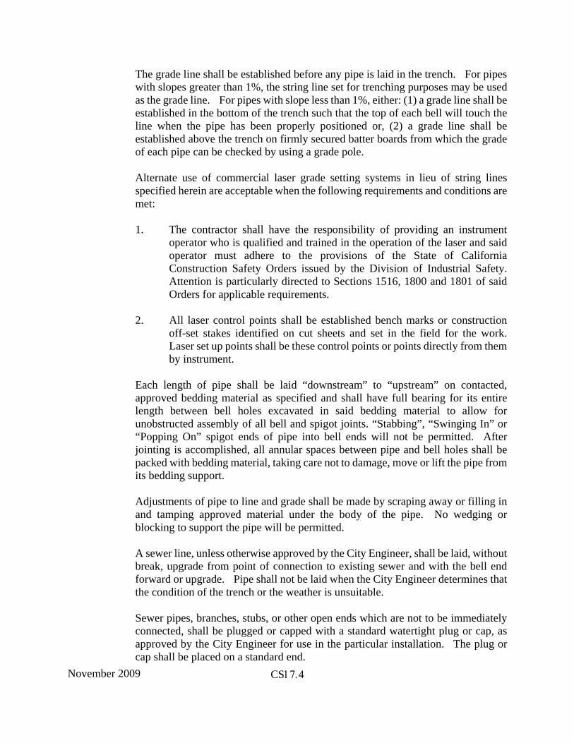
The grade line shall be established before any pipe is laid in the trench. For pipes with slopes greater than 1%, the string line set for trenching purposes may be used as the grade line. For pipes with slope less than 1%, either: (1) a grade line shall be established in the bottom of the trench such that the top of each bell will touch the line when the pipe has been properly positioned or, (2) a grade line shall be established above the trench on firmly secured batter boards from which the grade of each pipe can be checked by using a grade pole.
Alternate use of commercial laser grade setting systems in lieu of string lines specified herein are acceptable when the following requirements and conditions are met:
1. The contractor shall have the responsibility of providing an instrumentoperator who is qualified and trained in the operation of the laser and saidoperator must adhere to the provisions of the State of CaliforniaConstruction Safety Orders issued by the Division of Industrial Safety.Attention is particularly directed to Sections 1516, 1800 and 1801 of saidOrders for applicable requirements.
2. All laser control points shall be established bench marks or constructionoff-set stakes identified on cut sheets and set in the field for the work.Laser set up points shall be these control points or points directly from themby instrument.
Each length of pipe shall be laid “downstream” to “upstream” on contacted, approved bedding material as specified and shall have full bearing for its entire length between bell holes excavated in said bedding material to allow for unobstructed assembly of all bell and spigot joints. “Stabbing”, “Swinging In” or “Popping On” spigot ends of pipe into bell ends will not be permitted. After jointing is accomplished, all annular spaces between pipe and bell holes shall be packed with bedding material, taking care not to damage, move or lift the pipe from its bedding support.
Adjustments of pipe to line and grade shall be made by scraping away or filling in and tamping approved material under the body of the pipe. No wedging or blocking to support the pipe will be permitted.
A sewer line, unless otherwise approved by the City Engineer, shall be laid, without break, upgrade from point of connection to existing sewer and with the bell end forward or upgrade. Pipe shall not be laid when the City Engineer determines that the condition of the trench or the weather is unsuitable.
Sewer pipes, branches, stubs, or other open ends which are not to be immediately connected, shall be plugged or capped with a standard watertight plug or cap, as approved by the City Engineer for use in the particular installation. The plug or cap shall be placed on a standard end.
November 2009 CS17.5
Pipe entering or leaving manholes or other structures shall have joints within 2-1/2 feet of the manhole base.
In all cases, flexibility of joints in or at the manhole base shall be preserved to prevent damage to the pipe by differential settlement.
All sewer line connections to manholes, trunk sewers, main sewers or side sewers shall be left uncovered until after the inspection has been made. After the approval of the connection, the trench shall be backfilled as specified. The City Engineer may require special pipe to be laid in areas that are potentially unstable or subject to settlement.
If the sewer is to be laid in an area that is to be filled, and the cover prior to filling is less than 5 feet, the pipe shall not be laid until the area has been filled to a level 5 feet above the proposed pipe and compacted to 90% relative compaction, unless otherwise authorized by the City Engineer.
B. LATERALS: Service sewers shall be installed as detailed on Construction Detail 6030 and at the locations shown on the contract plans. Unless otherwise specified, they shall be 4 inches in diameter, of the same material as the sewer to which they connect, and constructed to the property line or easement. A regularly manufactured “Y” fitting shall be used in the lateral sewer for each sewer and shall be inclined upwards at a minimum angle of 10 degrees from the horizontal. The ends of all service sewers shall be securely sealed by stoppers in such a manner that the stoppers can be removed for extending the line without damage to the pipe. All sewer service connections after capping shall have a 4" x 4" stake installed above the cap to at least one foot above finish grade behind the back of walk. The 4" x 4" stake shall be painted green to indicate a sewer service. Unless otherwise noted on the plans, the depth of cover of the sewer service at the easement or property line shall be 5 feet to 5 feet 6 inches below existing ground or edge of adjacent roadway, whichever is at the lower elevation.
Service sewers entering a manhole shall be set with the invert of the service sewer level with the crown of the outgoing pipe.
When a service sewer is to be connected to an existing lateral or trunk sewer, the Contractor shall make the tap into the existing sewer under the direct supervision of the City Engineer. Notice shall be given at least 48 hours in advance of the proposed time of the tap.
1. CONNECTIONS TO MAINS IN STREETS: All service sewers are to beconstructed perpendicular to the street centerline, radially to manholes incul-de-sacs and radially to the street centerline on curved sections of streets.
2. CONNECTIONS TO MAINS IN EASEMENTS: Service sewers are to be
November 2009 CS17.6
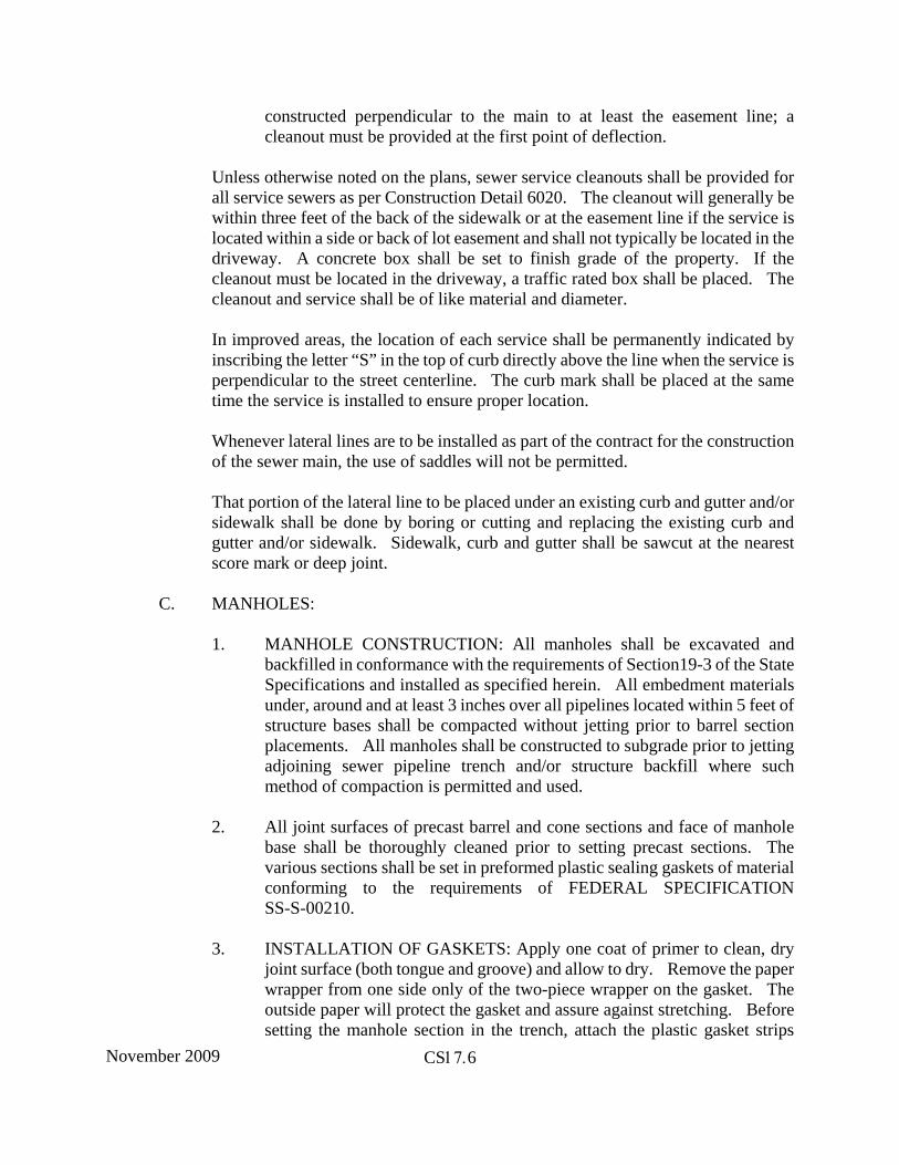
constructed perpendicular to the main to at least the easement line; a cleanout must be provided at the first point of deflection.
Unless otherwise noted on the plans, sewer service cleanouts shall be provided for all service sewers as per Construction Detail 6020. The cleanout will generally be within three feet of the back of the sidewalk or at the easement line if the service is located within a side or back of lot easement and shall not typically be located in the driveway. A concrete box shall be set to finish grade of the property. If the cleanout must be located in the driveway, a traffic rated box shall be placed. The cleanout and service shall be of like material and diameter.
In improved areas, the location of each service shall be permanently indicated by inscribing the letter “S” in the top of curb directly above the line when the service is perpendicular to the street centerline. The curb mark shall be placed at the same time the service is installed to ensure proper location.
Whenever lateral lines are to be installed as part of the contract for the construction of the sewer main, the use of saddles will not be permitted.
That portion of the lateral line to be placed under an existing curb and gutter and/or sidewalk shall be done by boring or cutting and replacing the existing curb and gutter and/or sidewalk. Sidewalk, curb and gutter shall be sawcut at the nearest score mark or deep joint.
C. MANHOLES:
1. MANHOLE CONSTRUCTION: All manholes shall be excavated andbackfilled in conformance with the requirements of Section19-3 of the StateSpecifications and installed as specified herein. All embedment materialsunder, around and at least 3 inches over all pipelines located within 5 feet ofstructure bases shall be compacted without jetting prior to barrel sectionplacements. All manholes shall be constructed to subgrade prior to jettingadjoining sewer pipeline trench and/or structure backfill where suchmethod of compaction is permitted and used.
2. All joint surfaces of precast barrel and cone sections and face of manholebase shall be thoroughly cleaned prior to setting precast sections. Thevarious sections shall be set in preformed plastic sealing gaskets of materialconforming to the requirements of FEDERAL SPECIFICATIONSS-S-00210.
3. INSTALLATION OF GASKETS: Apply one coat of primer to clean, dryjoint surface (both tongue and groove) and allow to dry. Remove the paperwrapper from one side only of the two-piece wrapper on the gasket. Theoutside paper will protect the gasket and assure against stretching. Beforesetting the manhole section in the trench, attach the plastic gasket strips
November 2009 CS17.7
end-to-end to the tongue or groove of each joint, forming a continuous gasket around the entire circumference of the manhole joint.
Handling of barrel sections after the plastic gasket has been affixed shall be carefully controlled to avoid bumping the gasket and thus displacing it or contaminating it with dirt or other foreign material. Any gaskets so disturbed shall be removed and replaced if damaged and repositioned if displaced.
Care shall be taken to properly align the manhole section with the previously set section before it is lowered into position.
During cold or wet weather, pass direct heat over the concrete joint surface lightly until ice, frost and moisture are removed and surface to be primed is dry and warm immediately before application of primer. Direct heat shall also be passed over plastic gasket strips immediately prior to attaching them to joint surfaces and immediately prior to insertion of tongue and groove.
Precast concrete bases shall be required when SDR 26 PVC pipes are used. Cast-in-place concrete bases shall be 4,000 psi, 28 day concrete with 1-1/2" maximum size aggregate. It shall rest on firm, undisturbed soil and shall be of the dimensions shown on the Construction Details. The cast-in-place portion shall not be higher than 6 inches above the outside tops of the main incoming and outgoing pipes. Rebar, as required, shall be placed in the bottoms and sides of the cast portion, subject to inspection by the City Engineer. Minimum and maximum wall thickness for the cast-in-place sections shall conform to the following table:
Manhole Diameter Minimum Wall Thickness
Maximum Wall Thickness
48 inches 5 inches 7 inches
60 inches 6 inches 8 inches
72 inches 7 inches 9 inches
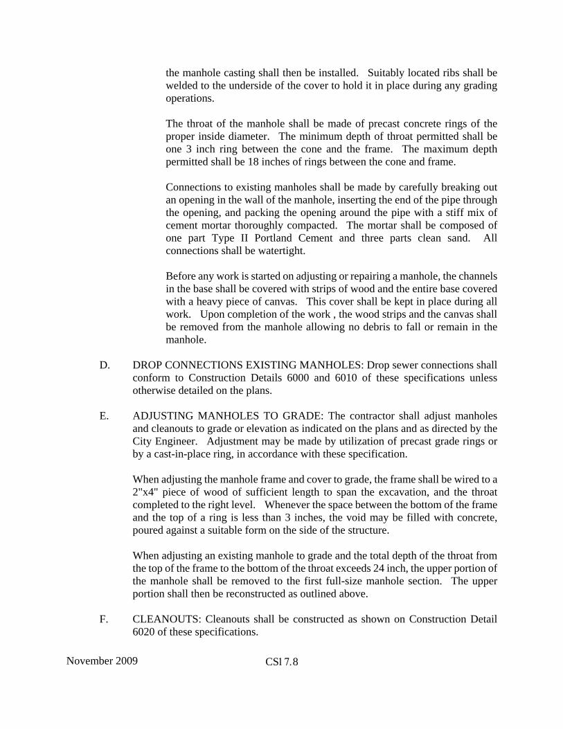
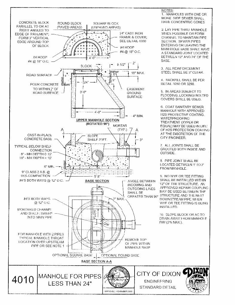
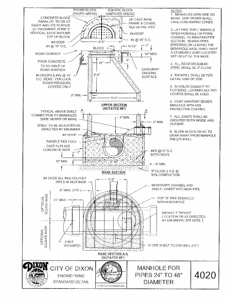
Where the sewer lines pass through manholes, the pipe shall be laid continuously as a whole pipe. After the manhole base and precast sections have been placed and sufficient time has elapsed to allow all concrete and grout to set, the top half of the pipe within the manhole shall be carefully cut off and the sides mortared. All channels so formed shall be checked with a template and shall form a smooth flowing channel at all flow depths.
Temporary covers of 3/8 inch steel plate of sufficient size to adequately cover the opening shall be placed on the cone until the base is complete and
November 2009 CS17.8
the manhole casting shall then be installed. Suitably located ribs shall be welded to the underside of the cover to hold it in place during any grading operations.
The throat of the manhole shall be made of precast concrete rings of the proper inside diameter. The minimum depth of throat permitted shall be one 3 inch ring between the cone and the frame. The maximum depth permitted shall be 18 inches of rings between the cone and frame.
Connections to existing manholes shall be made by carefully breaking out an opening in the wall of the manhole, inserting the end of the pipe through the opening, and packing the opening around the pipe with a stiff mix of cement mortar thoroughly compacted. The mortar shall be composed of one part Type II Portland Cement and three parts clean sand. All connections shall be watertight.
Before any work is started on adjusting or repairing a manhole, the channels in the base shall be covered with strips of wood and the entire base covered with a heavy piece of canvas. This cover shall be kept in place during all work. Upon completion of the work , the wood strips and the canvas shall be removed from the manhole allowing no debris to fall or remain in the manhole.
D. DROP CONNECTIONS EXISTING MANHOLES: Drop sewer connections shall conform to Construction Details 6000 and 6010 of these specifications unless otherwise detailed on the plans.
E. ADJUSTING MANHOLES TO GRADE: The contractor shall adjust manholes and cleanouts to grade or elevation as indicated on the plans and as directed by the City Engineer. Adjustment may be made by utilization of precast grade rings or by a cast-in-place ring, in accordance with these specification.
When adjusting the manhole frame and cover to grade, the frame shall be wired to a 2"x4" piece of wood of sufficient length to span the excavation, and the throat completed to the right level. Whenever the space between the bottom of the frame and the top of a ring is less than 3 inches, the void may be filled with concrete, poured against a suitable form on the side of the structure.
When adjusting an existing manhole to grade and the total depth of the throat from the top of the frame to the bottom of the throat exceeds 24 inch, the upper portion of the manhole shall be removed to the first full-size manhole section. The upper portion shall then be reconstructed as outlined above.
F. CLEANOUTS: Cleanouts shall be constructed as shown on Construction Detail 6020 of these specifications.
November 2009 CS17.9
G. INSPECTION: The City Engineer shall at all times have access to the work during its construction, and the contractor shall provide proper and safe facilities for such access and inspection. The City Engineer shall be furnished with every reasonable facility for ascertaining that the materials and the workmanship are in accordance with the requirements and intentions of these specifications. All work done and all materials furnished shall be subject to his inspection and approval.
The work shall be done under the supervision and to the complete satisfaction of the City and in accordance with the laws of the State of California.
The inspection of the work shall not relieve the Contractor of any of his obligations to fulfill his contract as prescribed, and defective work shall be made good and unsuitable materials may be rejected, notwithstanding that such defective work and materials have been previously overlooked by the City Engineer and accepted or estimated for payment. See the General Provisions for details.
The Contractor, shall, at any time when requested, submit to the City Engineer properly authenticated documents or other satisfactory proof as to his compliance with the requirements of these Specifications.
H. TESTING OF SEWER LINES: All leakage tests shall be completed and approved after backfilling and prior to placing of permanent surfacing. All tests shall be performed at the expense of the Contractor. A test may be performed which enables the Contractor to determine the acceptability of the line prior to backfill.
1. CLEANING AND FLUSHING: Prior to performing a leakage test, the pipeinstallation shall be thoroughly cleaned. Cleaning shall be performed bythe Contractor by means of an inflatable rubber ball. The ball shall be of asize that will fit snugly into the pipe to be flushed. The ball shall be placedin the last cleanout or manhole on the pipe to be cleaned, and waterintroduced behind it. The ball shall pass through the pipe with only thepressure of the water impelling it. All debris flushed out ahead of the ballshall be removed at the first manhole where its presence is noted. If anywedged debris or damaged pipe shall stop the ball, the Contractor shallremove the obstruction. When a new sewer is connected to an existingline, cleaning and flushing shall be carried out to the first existing manholedownstream from the point of connection.
2. PVC DEFLECTION TEST: PVC pipe shall be tested consistent withASTM standards. After the PVC pipe is installed, cleaned and ready to beair tested, according to these specifications, the pipe deflection shall bechecked by means of a deflection mandrel, in the presence of the CityEngineer. A rigid mandrel, with a circular cross section having a diameter,as indicated by the following table, shall be pulled through the pipe by hand.The minimum length of the circular portion of the mandrel shall be equal tothe nominal inside diameter of the pipe.
November 2009 CS17.10
Nominal Average Diameter (Inches)
Average Inside Diameter (Inches)
Base Inside Diameter (Inches)
7.% Deflection Mandrel Diameter (Inches)
8 7.891 7.665 7.09
10 9.864 9.563 8.84
From the Uni-bell Plastic Pipe Association Handbook of PVC Pipe, Third Printing - May 1979.
Any section of PVC pipe that does not permit passage of the deflection mandrel will not be accepted, and said section shall be properly repaired and replaced, and remandreled, as directed by the City Engineer. All other testing shall be performed as required in these specifications for sanitary sewer pipe. If, because of the additional required testing, any section of PVC has to be repaired or replaced, that section shall be remandreled again as directed by the City Engineer. The additional deflection test shall be performed not sooner than 30 days after completion of densification and backfill.
3. MANHOLE VACUUM AIR TEST: Low-Pressure Air Testing of sanitarysewer systems shall include the Contractor air testing manholes inaccordance with provisions of A.S.T.M. C1244-02, “Standard TestMethod for Concrete Sewer Manholes by Negative Air Pressure (Vacuum)Test Prior to Backfill.”
LOW-PRESSURE AIR TEST: After completing backfill of a section ofsewer line, the Contractor shall at his expense, conduct a Line AcceptanceTest using low-pressure air. The test shall be performed using theequipment listed below, according to stated procedures and under thesupervision of the City Engineer. All test results shall be logged andsubmitted to the City Engineer, prior to placement of permanent surfacing.
a. EQUIPMENT: Equipment used shall meet the following minimumrequirements:
i. Pneumatic plugs shall have a sealing length equal to orgreater than the diameter of the pipe to be inspected.
ii. Pneumatic plugs shall resist internal test pressures withoutrequiring external bracing and blocking.
November 2009 CS17.11
iii. All air used shall pass through a single control panel.
iv. Three individual hoses shall be used for the followingconnections.
a) From control panel to pneumatic plugs for inflation.
b) From control panel to sealed line for introducing thelow pressure air.
c) From sealed line to control panel for continuallymonitoring the air pressure rise in the sealed line.
b. PROCEDURE: At least two minutes shall be allowed for the airpressure to stabilize.
After the stabilization period (3.5 psig minimum pressure in thepipe),the air hose from the control panel to the air supply shall bedisconnected. The portion of line being tested shall be termed“acceptable” if the time required in minutes for the pressure todecrease from 3.5 to 2.5 9 pounds per square inch, gage (psig) is notless than the time shown for the given diameters in the followingtable:
Pipe Diameter in Inches Seconds
4 122
6 184
8 245
110 306
12 367
15 460
For larger diameter pipe use the following formula:
Min. time in seconds = 30.6 x pipe diameter in inches
When the prevailing groundwater is above the sewer being tested, air pressure shall be increased 0.43 psi for each foot the water table is above the flow line of the sewer.
November 2009 CS17.12
If the time for the pressure to drop 0.5 psi is 125 percent or less of the time given in the table, the line shall immediately be repressurized to 3.0 psi and the test repeated.
For 6" and 8" pipe: If, during the 5 minute saturation period, pressure drops less than 0.5 psi after the initial pressurization and air is not added, the section undergoing test shall be “acceptable”.
If the test is not passed, the leak shall be found and repaired to the satisfaction of the City Engineer and the length of repaired line retested.
House sewer laterals shall be considered part of the main to which they are connected and no adjustment of test time shall be allowed to compensate for the smaller diameter of the laterals.
The pressure gauge used shall be supplied by the contractor and certified to have been calibrated within six months of the test.
If the installation fails to meet this requirement, the Contractor shall, at his/her own expense, determine the source of leakage. He/she shall then repair or replace all defective materials and/or workmanship and perform the air test as many times as necessary to achieve an acceptable test.
c. SAFETY: The air test may be dangerous if, because of ignorance orcarelessness, a line is improperly prepared. It is extremelyimportant that the various plugs be installed and braced in such away as to prevent blowouts. Since a force of 250 lbs. is exerted onan 8 inch plug by an internal pipe pressure of 5 psi, it should berealized that sudden expulsion of a poorly installed plug or of a plugthat is partially deflated before the pipe pressure is released can bedangerous.
As a safety precaution, pressurizing equipment should include aregulator set at 10 psi to avoid over-pressurizing and damaging anotherwise acceptable line. No one shall be allowed in the manholesduring testing. If the test is not passed in two trials, the leak shallbe located and repaired to the satisfaction of the City Engineer andthe line shall be retested at the Contractor’s expense.
The pressure gage used shall be supplied by the Contractor and shallhave minimum divisions of 0.10 psi, and shall have an accuracy of0.04 psi. Accuracy and calibration of the gauge shall be certifiedby a reliable testing firm.
November 2009 CS17.13
4. T.V. INSPECTION: Prior to acceptance of any sanitary sewer line by theCity, said line shall be inspected internally by television as outlined belowat the contractor’s expense. Also, not less than 11 months afteracceptance, prior to expiration of the one year warranty period, and duringperiods of highest groundwater (usually February through April), sewermains and laterals shall be ball and flushed and TV retested. Contractorshall submit DVD disk and logs to the City after implementing any repairsrequired of retest.
Defects such as high and low spots, joint separations, offset joints, chippedends, cracked or damaged pipe, infiltration points and debris in lines shallbe corrected by the contractor at his expense. For joint separations, lowspots and chipped ends, the following maximum acceptable limits willapply for eight and ten inch pipes:
a. The complete job is ready for television inspection when thefollowing work has been completed:
i. All sewer pipelines are installed and backfilled.
ii. All structures are in place, all channeling is complete andpipelines are accessible from structures.
iii. All other underground facilities, utility piping and conduitsare installed.
iv. Final street subgrading is complete and ready for asphalticconcrete surfacing.
v. Pipelines to be inspected have been preliminarily balled andflushed or cleaned with a high pressure cleaner.
vi. All other tests have been performed and deficienciesremedied.
b. When the above work is complete, the Contractor shall arrange forthe television inspection.
c. The Contractor of the project will notify the City in writing as to thescheduled date of the television inspections.
d. After conditions i through vi as outlined above are met, the entire
November 2009 CS17.14
job will be initially televised and recorded. The DVD disk and reports shall be delivered to the City.
e. DVD disk video recording shall be color format and the audio andvideo portions shall be free of electrical interference and excessivebackground noise.
f. The audio report shall be recorded by the operating technician onthe DVD disk as they are being produced and shall include thelocation of the sewer, the names or numbers of the manholesinvolved, the direction of travel and a description of all laterallocations and conditions in the sewerline as they are encounteredand their locations.
g. In addition to the audio report, a written report shall be requiredlisting all the information required in the audio report.
h. The Contractor will be notified in writing of any deficienciesrevealed by the television inspection that will require repair. Ifcorrective work is indicated and the Contractor wishes to view DVDdisk recording, he shall contact the City to set a time for viewingwith the City Engineer.
i. Corrective work shall be done. The cost shall be borne by theContractor.
j. Those portions of the pipeline system that have been corrected mustbe retelevised and recorded and the DVD disks and reportsdelivered to the City.
k. The procedure outlined in conditions “A” through “G” above will berepeated until all deficiencies observed by television inspectionhave been corrected to the complete satisfaction of the City.
l. All DVD disk recordings and reports become the property of theCity to be used as “As-Built” for future reference.
CS17-04. PAYMENT: A. PIPE: Payment for sanitary sewer pipe complete in place shall be per lineal foot
measured from the center of manhole to center of manhole following a line parallel to the grade of the sewer. Payment shall include the furnishing of all labor, materials, water, tools and equipment required to construct and complete in an efficient and workmanlike manner the excavation, bedding, backfill, furnishing and laying of pipe, dewatering, testing and all other work necessary to construct the sewer system in accordance with the plans and these specifications.
November 2009 CS17.15
Full compensation for all incidentals arising from this work shall be considered as included in the price paid per unit of measure and no further compensation shall be allowed.
B. STRUCTURES AND MANHOLES: The unit of measure for payment shall be per each unit. Payment shall be made at the bid price per item for each structure complete in place and shall be the average price for manholes of all depths and types indicated on the plans and in the Proposal. Payment shall include the cost of excavation, backfill, frames, covers, plates or reinforcing steel where required.
Full compensation for all incidentals arising from this work shall be considered as included in the price paid per unit of measure and no further compensation shall be allowed.
C. DROP CONNECTIONS: The Contractor shall bid a unit price per each for constructing inside drop connections at existing manholes, which shall include excavation and all labor and equipment necessary for completion of the drop connection in accordance with the plans.
Full compensation for all incidentals arising from this work shall be considered as included in the price paid per unit of measure and no further compensation shall be allowed.
D. MANHOLE ADJUSTMENT: Payment for adjusting manholes shall conform to Section 15-2.05A of the State Specifications, except that the unit price bid shall include all necessary excavation and backfill and that the unit price shall be the average of all depths and limits of adjustment required.
E. CLEANOUTS: The unit bid price for cleanouts shall include excavation, pipe precast concrete items, cast iron frame and cover, concrete backfill, and all other labor, equipment and materials necessary for completion of the cleanout in accordance with the plans and these specifications.
Full compensation for all incidentals arising from this work shall be considered as included in the price paid per unit of measure and no further compensation shall be allowed.
F. SERVICE SEWERS: The unit bid price for service sewers shall include the furnishing of materials necessary for construction of the services and all labor and materials necessary to excavate the trench, connect to existing manholes or lateral sewer, bed, place and joint the pipe and fitting, backfill the trench, inscribe the letter “S” on the curb, install the cleanout and all other work necessary to produce a complete installation in accordance with the Construction Details and specifications. The unit price bid shall be the average price for service sewers of all lengths as indicated on the plans and in the Proposal.
November 2009 CS17.16
Full compensation for all incidentals arising from this work shall be considered as included in the price paid per unit of measure and no further compensation shall be allowed.