Fracture analysis in piezoelectric semiconductors under a thermal load J. Sladek a,⇑ , V. Sladek a , E. Pan b , M. Wünsche a a Institute of Construction and Architecture, Slovak Academy of Sciences, 84503 Bratislava, Slovakia b Computer Modeling and Simulation Group, Department of Civil Engineering, University of Akron, Akron, OH 44325-3905, USA article info Article history: Received 25 March 2014 Received in revised form 21 May 2014 Accepted 27 May 2014 Available online 7 June 2014 Keywords: Meshless local Petrov–Galerkin method (MLPG) Moving least-squares approximation Piezoelectric solids Semiconductor Intensity factors Uncoupled thermoelasticity Impermeable conditions abstract In this paper, we solve the in-plane crack problem in piezoelectric semiconductors under a transient thermal load. General boundary conditions and sample geometry are allowed in the proposed formulation. The coupled governing partial differential equations (PDE) for stresses, electric displacement field and current are satisfied in a local weak-form on small fictitious subdomains. All field quantities are approximated by the moving least-squares (MLS) scheme. After performing the spatial integrations, we obtain a system of ordinary differential equations for the nodal unknowns. The influence of initial electron density on the intensity factors and energy release rate is investigated. Ó 2014 Elsevier Ltd. All rights reserved. 1. Introduction Piezoelectric materials (PZ) have a wide range of engineering applications in smart structures and devices. Certain piezo- electric materials are also temperature sensitive, i.e. an electric charge or voltage is generated when temperature variations are exposed. This effect is called the pyroelectric effect. If a temperature load is considered in a piezoelectric solid it is needed to take into account the coupling of thermo-electro-mechanical fields. The theory of thermo-piezoelectricity was for the first time proposed by Mindlin [22]. The physical laws for thermo-piezoelectric materials were explored by Nowacki [23]. Dynamic thermoelasticity is relevant for many engineering problems since thermal stresses play an important role in the integrity of structures. The uncoupled thermoelasticity is considered here, since there is no heat production due to the strain rate, i.e. the thermoelastic dissipation. Thus, the temperature field is not influenced by mechanical deformation and the heat conduction equation can be solved first to obtain the temperature distribution. However, the coupling of mechanical and electric fields is still valid. Recently, Sladek et al. [39] analyzed non-conducting piezoelectric materials under a thermal load. However, piezoelectric materials can be either dielectrics or semiconductors. Up to date dielectric materials are more intensively investigated than semiconductors. The analyzed problem for non-conducting PZ is simpler than for semiconduc- tors. In piezoelectric semiconductors the induced electric field produces also the electric current. The interaction between mechanical fields and mobile charges in piezoelectric semiconductors is called the acoustoelectric effect [18,50]. An acoustic wave traveling in a PZ semiconductor can be amplified by application of an initial or biasing direct current electric field [44]. http://dx.doi.org/10.1016/j.engfracmech.2014.05.011 0013-7944/Ó 2014 Elsevier Ltd. All rights reserved. ⇑ Corresponding author. E-mail address: [email protected](J. Sladek). Engineering Fracture Mechanics 126 (2014) 27–39 Contents lists available at ScienceDirect Engineering Fracture Mechanics journal homepage: www.elsevier.com/locate/engfracmech
J. Sladek a,⇑, V. Sladek a, E. Pan b, M. Wünsche a
a Institute of Construction and Architecture, Slovak Academy of Sciences, 84503 Bratislava, Slovakiab Computer Modeling and Simulation Group, Department of Civil Engineering, University of Akron, Akron, OH 44325-3905, USA
a r t i c l e i n f o
Article history:Received 25 March 2014Received in revised form 21 May 2014Accepted 27 May 2014Available online 7 June 2014
Keywords:Meshless local Petrov–Galerkin method(MLPG)Moving least-squares approximationPiezoelectric solidsSemiconductorIntensity factorsUncoupled thermoelasticityImpermeable conditions
a b s t r a c t
In this paper, we solve the in-plane crack problem in piezoelectric semiconductors under atransient thermal load. General boundary conditions and sample geometry are allowed inthe proposed formulation. The coupled governing partial differential equations (PDE) forstresses, electric displacement field and current are satisfied in a local weak-form on smallfictitious subdomains. All field quantities are approximated by the moving least-squares(MLS) scheme. After performing the spatial integrations, we obtain a system of ordinarydifferential equations for the nodal unknowns. The influence of initial electron densityon the intensity factors and energy release rate is investigated.
� 2014 Elsevier Ltd. All rights reserved.
1. Introduction
Piezoelectric materials (PZ) have a wide range of engineering applications in smart structures and devices. Certain piezo-electric materials are also temperature sensitive, i.e. an electric charge or voltage is generated when temperature variationsare exposed. This effect is called the pyroelectric effect. If a temperature load is considered in a piezoelectric solid it is neededto take into account the coupling of thermo-electro-mechanical fields. The theory of thermo-piezoelectricity was for the firsttime proposed by Mindlin [22]. The physical laws for thermo-piezoelectric materials were explored by Nowacki [23].Dynamic thermoelasticity is relevant for many engineering problems since thermal stresses play an important role in theintegrity of structures. The uncoupled thermoelasticity is considered here, since there is no heat production due to the strainrate, i.e. the thermoelastic dissipation. Thus, the temperature field is not influenced by mechanical deformation and the heatconduction equation can be solved first to obtain the temperature distribution. However, the coupling of mechanical andelectric fields is still valid. Recently, Sladek et al. [39] analyzed non-conducting piezoelectric materials under a thermal load.
However, piezoelectric materials can be either dielectrics or semiconductors. Up to date dielectric materials are moreintensively investigated than semiconductors. The analyzed problem for non-conducting PZ is simpler than for semiconduc-tors. In piezoelectric semiconductors the induced electric field produces also the electric current. The interaction betweenmechanical fields and mobile charges in piezoelectric semiconductors is called the acoustoelectric effect [18,50]. An acousticwave traveling in a PZ semiconductor can be amplified by application of an initial or biasing direct current electric field [44].
Latin symbolsa crack-lengthc specific heatcijkl elasticity tensordij carrier diffusion tensoreijk piezoelectric tensorhij dielectric tensorkij thermal conductivitynj outward unit normal vectorpj pyroelectric material coefficientspT vector of complete basis functionsq electric charge of electronti traction vectorui elastic displacementsu�ik test functionw⁄ test functionwa weight functionDi electric displacementsEi electric fieldG energy release rateJi electric currentKI, KII stress intensity factorsKD electric displacement intensity factorKc strain intensity factorKE electric vector intensity factorM electron densityNa shape function associated with the node a
Greek symbolsbij linear thermal expansiondij Kronecker deltaeij strain tensor/ electric potentialkij stress-temperature moduluslij electron mobility tensorm⁄ test functionq mass densityrij stress tensors timeCu boundary with prescribed displacementsCt boundary with prescribed tractionsCp boundary with prescribed electric potentialCq boundary with prescribed normal component of the electric displacementsCa boundary with prescribed electron densityCb boundary with prescribed electric current fluxCe boundary with prescribed temperatureCf boundary with prescribed heat fluxXS local subdomain@XS boundary of the local subdomain
Other symbolsf, i partial derivative of the function f_f time derivative of the function f
28 J. Sladek et al. / Engineering Fracture Mechanics 126 (2014) 27–39
This phenomenon is utilized in many acoustoelectric devices [15,4]. In literature one can find also more sophisticated modelsof deformable piezoelectric semiconductors [52,53]. Lorenzi and Tiersten [52] derived governing equations for finitelydeformable, polarized and magnetizable heat conducting and electrically semiconducting continuum. The model consists
J. Sladek et al. / Engineering Fracture Mechanics 126 (2014) 27–39 29
of five suitably defined interpenetrating continua. The relative displacement of the bound electronic continuum with respectto the lattice continuum produces electrical polarization, and electrical conduction results from the motion of the chargedfree electronic and hole fluids. However, this model seems to be complicated for treatment of wave-interaction problems.Later, Maugin and Dahar [53] derived linearized governing equations for piezoelectric semiconducting crystals on the baseof fully nonlinear theory of the continuum. While more sophisticated models require more advanced computational meth-ods, there is even no available modeling result for simpler models like the Hutson and White linear model [18].
Piezoelectric ceramics are brittle and susceptible to fracture during service. To improve the performance and to predictthe reliable service lifetime of ceramic piezoelectric components, it is necessary to analyze theoretically the damage andfracture processes taking place in piezoelectric materials with consideration of the coupling effect of mechanics and electrics.Deeg [5] and Pak [25] addressed the plane and anti-plane fracture problems of an infinite piezoelectric body and obtainedthe closed form solutions of stress field and electric displacement field near the crack tip. There are only few papers devotedto crack problems in piezoelectric semiconductor materials. These papers concerned only the anti-plane crack problem inunbounded domain with a semi-infinite crack [43] or a finite crack [17] under stationary conditions. The Fourier transformtechnique was applied to reduce the problem to a pair of dual integral equations. In the present paper, we aim at analyzingthe in-plane crack problem in bounded domains under a transient thermal load.
The solution of the boundary value problems for conducting piezoelectric solids requires advanced numerical methodsdue to the high mathematical complexity. Transient regime brings additional complications. Thus, efficient computationalmethods to solve the boundary or the initial-boundary value problems for piezoelectric solids are required. Notably, thefinite element method (FEM) [13,12,7,19] and boundary element method (BEM) [26,20,6,14,9,10,30,34] were applied to solvegeneral piezoelectric problems. Fracture and damage behaviours of a cracked piezoelectric solid under coupled thermal,mechanical and electrical loads were studied by Yu and Qin [45,46]. A review on fracture of thermo-piezoelectric materialswas given by Qin [28]. Boundary value problems for coupled fields are complex. Analytical methods can be only applied tosimple problems of thermo-piezoelectricity [41,32,33]. However, the analysis and design process of smart engineering struc-tures with integrated piezoelectric actuators or sensors require powerful calculation tools. Up to now the FEM provides aneffective technique [42,11,31] in a homogeneous medium. Rao and Sunar [29] investigated the piezothermoelectric problemof intelligent structures with distributed piezoelectric sensors and actuators and concluded that the inclusion of the thermaleffects may help improve the performance characteristics of the system.
In recent years, meshless formulations are becoming popular due to their high adaptivity and low costs to prepare inputand output data for numerical analyses. A variety of meshless methods has been proposed so far and some of them are alsoapplied to PZ problems [24,21,36–39]. They can be derived either from a weak-form formulation on the global domain or ona set of local subdomains. In this paper, both the heat conduction equation and coupled electro-mechanical governing equa-tions are satisfied in a weak form on small fictitious subdomains. The meshless Petrov–Galerkin (MLPG) method [35] is thenapplied to the subdomains. Nodal points are introduced and spread on the analyzed domain and each node is surrounded bya small circle for simplicity, but without loss of generality. The spatial variations of the displacement, electric potential andelectron density are approximated by the moving least-squares (MLS) scheme [51]. After performing the spatial integrations,a system of ordinary differential equations for unknown nodal values is obtained. The essential boundary conditions on theglobal boundary are satisfied by the collocation. Then, the system of the ordinary differential equations of the second orderresulting from the equations of motion is solved by the Houbolt finite-difference scheme [16] and backward differencemethod.
2. Local integral equations for piezoelectric semiconductor
Consider a homogeneous n-type piezoelectric semiconductor with electron density M0 in the unloaded state with vanish-ing initial electric field E0. Supposing the frequency of external loadings to be close to the characteristic frequency of elasticwaves, one can assume quasi-static approximation for electromagnetic fields. Then, the effect of Faraday’s induction isneglected even if there is a magnetic field induced by the electric current according to the Ampere’s law. Eventually, the gov-erning equations within the linear theory are given by the balance of momentum, Gauss‘s law and conservation of charge[18]
where €ui, rij, Di, and q are the acceleration of elastic displacements, stress tensor, electric displacement field, and electriccharge of electron, respectively. The electron density and electric current are denoted by M and Ji, respectively. Symbol qis used for the mass density. A comma followed by an index denotes partial differentiation with respect to the coordinateassociated with the index.In uncoupled thermo-elastic theory the temperature distribution is independent on mechanicaland electrical fields. The governing Eq. (1) have to be supplemented by the heat conduction equation
½kijðxÞh;jðx; sÞ�;i � qc _hðx; sÞ ¼ 0; ð2Þ
where kij and c are the thermal conductivity tensor and specific heat, respectively.
30 J. Sladek et al. / Engineering Fracture Mechanics 126 (2014) 27–39
For most materials the inverse thermoelastic and pyroelectric effects are very weak, i.e. the heat generation by mechan-ical and electrical fields can be neglected. Then, the constitutive equations [18,50] need to be supplied only with thermalterms [39]
where cijkl(x), eijk(x), hij(x), lij(x), dij(x) and pj(x) are the elastic, piezoelectric, dielectric, electron mobility, carrier diffusionand pyroelectric material coefficients, respectively. Generally, these coefficients can be dependent on Cartesian coordinatesin functionally graded materials. Recall that the Joule heating (heat generated by a current passing through a resistive mate-rial), the Seebeck effect (when a temperature gradient generates an electromotive force in a conductor) as well as the Thom-son effect (production of heat rate due to temperature gradient when an electric current passes through a conductor) areomitted in the considered model. The stress–temperature modulus kijðxÞ can be expressed through the stiffness coefficientsand the coefficients of linear thermal expansion bkl
kij ¼ cijklbkl;
since the thermal expansion strains are given as eTkl ¼ bklh.
For an orthotropic material, the thermal expansion cannot induce shear, hence the coefficient tensor bkl takes the form
bkl ¼ b11dk1dl1 þ b22dk2dl2 þ b33dk3dl3:
The strain tensor eij and the electric field vector Ej are related to the displacements ui and the electric potential / by
eij ¼12ðui;j þ uj;iÞ; Ej ¼ �/;j: ð4Þ
The governing Eqs. (1)–(4) are for general three-dimensional deformation/motion. In the case of certain crystal symme-tries, one can formulate also the plane-deformation problems [27]. For instance, in the crystals of hexagonal symmetry withx3 being the 6-order symmetry axis and assuming u2 = 0 as well as the independence on x2, i.e. ( � ),2 = 0, we have e22 = e23 =e12 = E2 = J2 = 0, b22 = 0. Thus, the problem is reduced to the two-dimensional (x1,x3)-plane as we will discuss in this paperwith the coordinate vector x being x = (x1,x3).
Using the Voigt notation, the constitutive Eq. (3) are reduced to the following form
r11
r33
r13
264375 ¼ c11 c13 0
c13 c33 00 0 c44
264375 e11
e33
2e13
264375� 0 e31
0 e33
e15 0
264375 E1
E3
� �� kh ¼ CðxÞ
e11
e33
2e13
264375� LðxÞ
E1
E3
� �� kðxÞh ð5Þ
D1
D3
� �¼
0 0 e15
e31 e33 0
� � e11
e33
2e13
264375þ h11 0
0 h33
� �E1
E3
� �þ
p1
p2
� �h ¼ GðxÞ
e11
e33
2e13
264375þHðxÞ
E1
E3
� �þPðxÞh ð6Þ
J1
J3
� �¼ qm0
l11 00 l33
� �E1
E3
� �� q
d11 00 d33
� �M;1
M;3
� �¼ qm0AðxÞ
E1
E3
� �� qFðxÞ
M;1
M;3
� �ð7Þ
where
k ¼k11
k33
k13
264375 ¼ c11 c13 0
c13 c33 00 0 c44
264375 b11
b33
0
264375 ¼ k11
k33
0
264375:
The following essential and natural boundary conditions are assumed for the mechanical fields
Sðx; sÞ � Jiðx; sÞniðxÞ ¼ eSðx; sÞ; on Cb;C ¼ Ca [ Cb;
J. Sladek et al. / Engineering Fracture Mechanics 126 (2014) 27–39 31
and for the thermal fields
hðx; sÞ ¼ ~hðx; sÞ on Ce;
fðx; sÞ � kijh;jðx; sÞniðxÞ ¼ ~fðx; sÞ on Cf ;C ¼ Ce [ Cf ;
where Cu is the part of the global boundary C with prescribed displacements, while on Ct, Cp, Cq, Ca, Cb, Ce and Cf the trac-tion vector, the electric potential, the normal component of the electric displacement vector, the electron density, the electriccurrent flux, the temperature and the heat flux are prescribed, respectively. Recall that eQ ðx; sÞ can be considered approxi-mately as the surface density of the free charge, provided that the permittivity of the solid is much greater than that ofthe surrounding medium (vacuum).
The initial conditions for the mechanical displacements are assumed as
uiðx; sÞjs¼0 ¼ uiðx;0Þ and _uiðx; sÞjs¼0 ¼ _uiðx; 0Þ in X:
As shown by Atluri et al. [2] the local weak form of the governing equations (1) can be written with
ZXs
rij;jðx; sÞ � q€uiðx; sÞ� �
u�ikðxÞdX ¼ 0; ð8Þ
where u�ikðxÞ is a test function and Xs �X.Applying the Gauss divergence theorem to the first integral, we obtain
Z
@Xs
rijðx; sÞnjðxÞu�ikðxÞdC�Z
Xs
rijðx; sÞu�ik;jðxÞdX�Z
Xs
q€uiðx; sÞu�ikðxÞdX ¼ 0; ð9Þ
where the boundary of the local subdomain @ Xs consists of three parts @ Xs = Ls [ Cst [ Csu [1]. Here, Ls is the local boundarythat is totally inside the global domain, Cst is the part of the local boundary which coincides with the global traction bound-ary, i.e., Cst = @ Xs \ Ct, and similarly Csu is the part of the local boundary that coincides with the global displacement bound-ary, i.e., Csu = @ Xs \ Cu. Similar definitions are valid also for other fields and related integration parts.
By choosing the characteristic function as the test function u�ikðxÞ in each subdomain
u�ikðxÞ ¼dik at x 2 Xs
0 at x R Xs
�;
the local weak-form (9) is converted into the following local boundary-domain integral equations
ZLs
tiðx; sÞdC�Z
Xs
q€uiðx; sÞdX ¼ �Z
Cst
~tiðx; sÞdC: ð10Þ
Eq. (10) is recognized as the overall force equilibrium conditions on the subdomain Xs. Note that the local integral Eq. (10)is valid for both the homogeneous and nonhomogeneous solids. Nonhomogeneous material properties are included in Eq.(10) through the elastic, piezoelectric, and thermo-elastic coefficients involved in the traction components
32 J. Sladek et al. / Engineering Fracture Mechanics 126 (2014) 27–39
The local weak-form of the heat conduction Eq. (2) can be written as
ZXs
kijðxÞh;jðx; sÞ� �
;i � qc _hðx; sÞn o
w�ðxÞ dX ¼ 0; ð14Þ
where w⁄(x) is a test function.Applying the Gauss divergence theorem to the local weak-form and considering the characteristic function for the test
function w⁄(x), we also obtain
ZLs
fðx; sÞdC�Z
Xs
qc _hðx; sÞdX ¼ �Z
Csf
~fðx; sÞdC; ð15Þ
where the heat flux is defined as
fðx; sÞ � kijh;jðx; sÞniðxÞ:
3. Numerical solution in terms of the MLPG method
In the MLPG method the test and the trial functions are not necessarily from the same functional spaces. For internalnodes, the test function is chosen as a unit step function with its support on the local subdomain. The trial functions, onthe other hand, are chosen to be the MLS approximations by using a number of nodes spreading over the domain ofinfluence. According to the MLS method (see e.g. Belytschko et al. [3]), the approximation of the displacement field canbe given as
uhðxÞ ¼Xs
i¼1
piðxÞaiðxÞ ¼ pTðxÞaðxÞ; ð16Þ
where pT(x) = {p1(x), p2(x), ...ps(x)} is a vector of complete basis functions of order s and a(x) = {a1(x), a2(x), ...as(x)} is a vectorof unknown parameters that depend on x. For example, in 2-D problems
pTðxÞ ¼ f1; x1; x3g for s ¼ 3
and
pTðxÞ ¼ f1; x1; x3; x21; x1x3; x2
3g for s ¼ 6
are linear and quadratic basis functions, respectively. The basis functions are not necessary to be polynomials. It is conve-nient to introduce r�1/2 – singularity for secondary fields at the crack-tip vicinity for modeling fracture problems [8]. Then,the basis functions can be considered in the following form
pTðxÞ ¼ f1; x1; x3;ffiffiffirp
cosðh=2Þ;ffiffiffirp
sinðh=2Þ;ffiffiffirp
sinðh=2Þ sin h;ffiffiffirp
cosðh=2Þ sin hg for s ¼ 7;
where r and h are polar coordinates with the crack-tip as the origin. These enriched basic functions represent all occurringterms in asymptotic expansion of displacements at the crack tip vicinity. Then, density of node distribution in such a case canbe lower than in the polynomial basis functions at the same accuracy of results.
Following the approximation (16), the approximated functions for the mechanical displacements, the electric potential,electron density and the temperature can be written as Atluri [1]
uhðx; sÞ ¼¼Xn
a¼1
NaðxÞuaðsÞ;
/hðx; sÞ ¼Xn
a¼1
NaðxÞ/aðsÞ;
Mhðx; sÞ ¼Xn
a¼1
NaðxÞ bMaðsÞ;
hhðx; sÞ ¼Xn
a¼1
NaðxÞhaðsÞ; ð17Þ
where the nodal values uaðsÞ ¼ ðua1ðsÞ; ua
3ðsÞÞT , /aðsÞ, bMaðsÞ, and haðsÞ are fictitious parameters for the displacements, electric
potential, electron density and the temperature, respectively, and Na(x) is the shape function associated with the node a. Thenumber of nodes n used for the approximation is determined by the weight function wa(x). A 4th-order spline-type weightfunction is applied in the present work
waðxÞ ¼ 1� 6 da
ra
� 2þ 8 da
ra
� 3� 3 da
ra
� 4; 0 6 da
6 ra
0; da P ra
8<: ; ð18Þ
J. Sladek et al. / Engineering Fracture Mechanics 126 (2014) 27–39 33
where da = kx - xak and ra is the size of the support domain. It is seen that the C1 – continuity is ensured over the entiredomain, and therefore the continuity conditions of the tractions, the electric charge, the electric current flux and the heatflux are satisfied. In the MLS approximation the rates of the convergence of the solution may depend upon the nodal distanceas well as the size of the supporting domain [47–49]). It should be noted that a smaller size of the subdomains may inducelarger oscillations in the nodal shape functions [1]. A necessary condition for a regular MLS approximation is that at least mweight functions are non-zero (i.e. n P s) for each sample point x e X. This condition determines the size of the supportingdomain.
Then, the traction vector ti(x, s) at a boundary point x e @ Xs is approximated in terms of the same nodal values uaðsÞ as
thðx; sÞ ¼ NðxÞCðxÞXn
a¼1
BaðxÞuaðsÞ þNðxÞLðxÞXn
a¼1
PaðxÞ/aðsÞ �NðxÞkðxÞXn
a¼1
NaðxÞhaðsÞ; ð19Þ
where the matrices C(x), L(x) are defined in Eq. (5), the matrix NðxÞ is related to the normal vector n(x) on @ Xs by
NðxÞ ¼n1 0 n3
0 n3 n1
� �;
and finally, the matrices Ba and Pa are represented by the gradients of the shape functions as
BaðxÞ ¼Na;1
0Na;3
0Na;3
Na;1
264375; PaðxÞ ¼
Na;1
Na;3
" #:
Similarly the normal component of the electric displacement vector Q(x, s) can be approximated by
Q hðx; sÞ ¼ N1ðxÞGðxÞXn
a¼1
BaðxÞuaðsÞ � N1ðxÞHðxÞXn
a¼1
PaðxÞ/aðsÞ þ N1ðxÞPðxÞXn
a¼1
NaðxÞhaðsÞ; ð20Þ
where the matrices G(x), H(x), P(x) are defined in Eq. (6) and
N1ðxÞ ¼ n1 n3½ �:
Eventually, the electric current flux S(x, s) is approximated by
Shðx; sÞ ¼ �N1ðxÞqM0AðxÞXn
a¼1
PaðxÞ/aðsÞ � N1ðxÞqFðxÞXn
a¼1
PaðxÞ bMaðsÞ; ð21Þ
with the matrices A(x), F(x) being defined in Eq. (7).The heat flux f(x, s) is approximated by
fhðx; sÞ ¼ kijni
Xn
a¼1
Na;jðxÞhaðsÞ ¼ N1ðxÞHðxÞ
Xn
a¼1
PaðxÞhaðsÞ; ð22Þ� �
where HðxÞ ¼ k11 k13
k13 k33.
Satisfying the essential boundary conditions and making use of the approximation formulae (17), we obtain the discret-ized form of these boundary conditions as
Xn
a¼1
NaðxÞuaðsÞ ¼ ~uðx; sÞ for x 2 Cu;
Xn
a¼1
NaðxÞ/aðsÞ ¼ ~/ðx; sÞ for x 2 Cp;
Xn
a¼1
NaðxÞ bMaðsÞ ¼ ~Mðx; sÞ for x 2 Ca;
Xn
a¼1
NaðxÞhaðsÞ ¼ ~hðx; sÞ for x 2 Ce: ð23Þ
Furthermore, in view of the MLS-approximations (19)–(22) for the unknown quantities in the local boundary-domainintegral Eqs. (10), (12), (13), and (15), we obtain their discretized forms as
34 J. Sladek et al. / Engineering Fracture Mechanics 126 (2014) 27–39
Xn
a¼1
ZLs
NðxÞCðxÞBaðxÞdC �
uaðsÞ �Z
Xs
qðxÞNadX �
€uaðsÞ� �
þXn
a¼1
ZLs
NðxÞLðxÞPaðxÞdC �
/aðsÞ
�Xn
a¼1
ZLs
NðxÞkðxÞNaðxÞdC �
haðsÞ ¼ �Z
Cst
~tðx; sÞdC; ð24Þ
Xn
a¼1
ZLs
N1ðxÞGðxÞBaðxÞdC �
uaðsÞ �Xn
a¼1
ZLs
N1ðxÞHðxÞPaðxÞdC �
/aðsÞ þXn
a¼1
ZLs
N1ðxÞPðxÞNaðxÞdC �
haðsÞ
�Xn
a¼1
ZXs
qNaðxÞdX � bMaðsÞ ¼ �
ZCsq
eQ ðx; sÞdC; ð25Þ
�Xn
a¼1
ZLs
N1ðxÞqM0AðxÞPaðxÞdC �
/aðsÞ �Xn
a¼1
ZLs
N1ðxÞqFðxÞPaðxÞdC � bMaðsÞ
þXn
a¼1
ZXs
qNaðxÞdX �
_bMaðsÞ ¼ �Z
Csb
~Sðx; sÞdC; ð26Þ
Xn
a¼1
ZLs
N1ðxÞHðxÞPaðxÞdC �
haðsÞ �Z
Xs
qcNaðxÞdC �
_haðsÞ� �
¼ �Z
Csf
~fðx; sÞdC; ð27Þ
which are considered on the sub-domains adjacent to the interior nodes as well as to the boundary nodes on Cst, Csq, Csb andCsf.
Collecting the discretized local boundary-domain integral equations, together with the discretized boundary conditionsfor the displacements, electric potential, electron density, and the temperature, results in a complete system of ordinarydifferential equations, which can be rearranged in such a way that all known quantities are on the r.h.s of an equation. Thus,in the matrix form the system becomes
A€FðsÞ þ B _FðsÞ þ CFðsÞ ¼ YðsÞ; ð28Þ
where the vector F contains all the unknowns to be solved, as listed in (23). We point out again that the system matrix has ablock structure and the thermal unknowns can be solved separately from the mechanical and electric unknowns.
There are many time integration procedures for the solution of this system of ordinary differential equations. In the pres-ent work, the Houbolt method is applied. In the Houbolt finite- difference scheme [16], the ‘‘acceleration’’ is expressed as
€FsþDs ¼2FsþDs � 5Fs þ 4Fs�Ds � Fs�2Ds
Ds2 ; ð29Þ
where Ds is the time step. The backward difference method is applied for the approximation of ‘‘velocities’’
_FsþDs ¼FsþDs � Fs
Ds: ð30Þ
Substituting Eqs. (29) and (30) into Eq. (28), we get the following system of algebraic equations for the unknowns Fs+Ds
2Ds2 Aþ 1
DsBþ C
� �FsþDs ¼
1Ds2 ð5Aþ BDsÞFs þ A
1Ds2 f�4Fs�Ds þ Fs�2Dsg þ Y: ð31Þ
The value of the time step has to be appropriately selected with respect to material parameters (wave velocities) and timedependence of the boundary conditions.
Fig. 1. A central crack in a finite strip with prescribed temperatures on the outer boundary and crack surfaces.
J. Sladek et al. / Engineering Fracture Mechanics 126 (2014) 27–39 35
4. Numerical examples
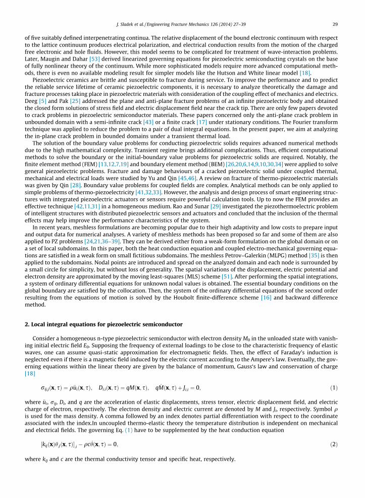
As numerical examples, we analyze a straight central crack in a finite strip under a thermal load. The geometry of the stripis given in Fig. 1 with the following values: a = 0.5 m, a/w = 0.4 and h/w = 1.2. On the outer boundary of the strip~ti ¼ 0; eQ ¼ 0 and ~t2 ¼ h0 ¼ 1 deg, while on the crack surface ~ti ¼ 0;~t1 ¼ 0; eS ¼ 0 and electrically impermeable boundary con-ditions are assumed.
Due to the symmetry of the problem with respect to both Cartesian coordinates, only a quarter of the strip is modeled. Weuse 930 (31 � 30) nodes equidistantly distributed for the MLS approximation of the physical quantities. The local subdo-mains are considered to be circular with a radius of rloc = 0.033 m. The material properties correspond to aluminium nitride(AlN)
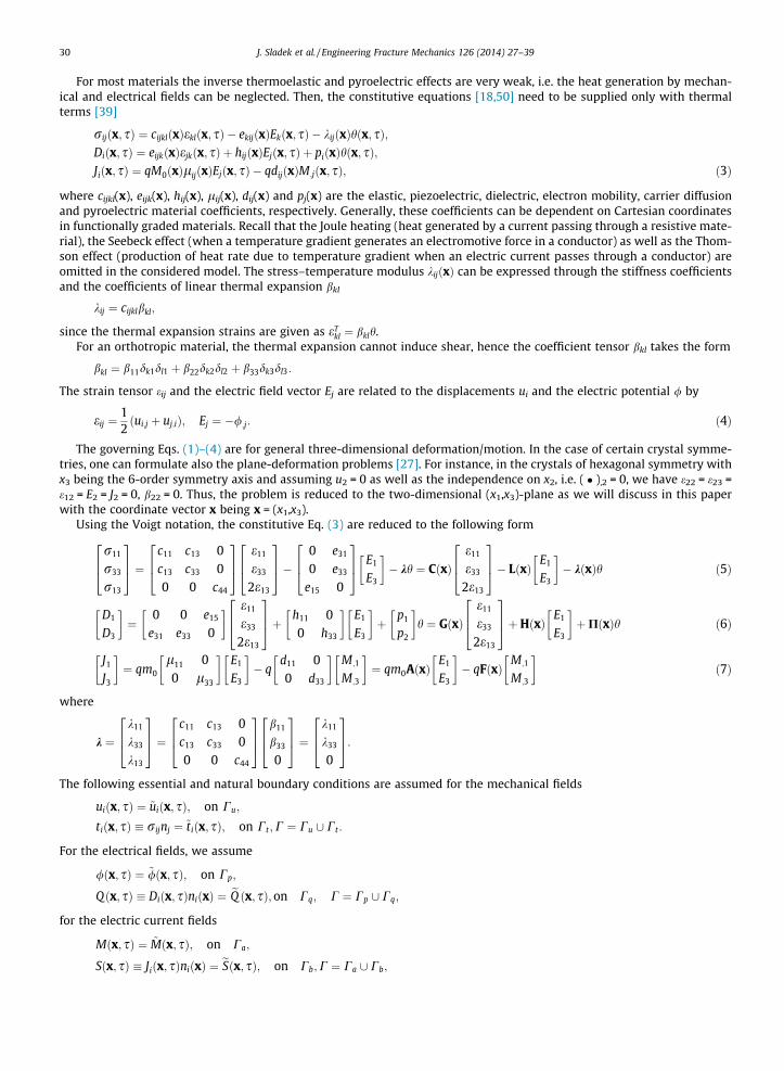
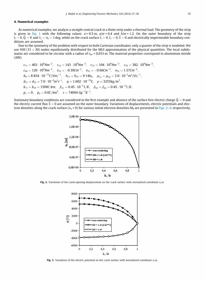
Stationary boundary conditions are considered in the first example and absence of the surface free electric charge eQ ¼ 0 andthe electric current flux eS ¼ 0 are assumed on the outer boundary. Variations of displacements, electric potentials and elec-tron densities along the crack surface (x3 = 0) for various initial electron densities M0 are presented in Figs. 2–4, respectively.
Fig. 2. Variations of the crack-opening-displacement on the crack surface with normalized coordinate x1/a.
Fig. 3. Variations of the electric potential on the crack surface with normalized coordinate x1/a.
Fig. 4. Variation of the electron density M on the crack surface normalized coordinate x1/a.
36 J. Sladek et al. / Engineering Fracture Mechanics 126 (2014) 27–39
The presented numerical results correspond to a pure thermal load. One can observe while the initial electron density hasonly a small influence on the crack displacement, it strongly affects the induced electric potential. The largest value of theinduced potential is for a non-conducting PZ material, and with increasing value of M0, the induced electric potentialdecreases. Furthermore, the distribution of the electron density on the crack surface is also strongly dependent on M0 value.A higher value of M0 results in a higher density of electrons M.
For cracks in homogeneous and linear piezoelectric solids, the asymptotic behaviour of the field quantities was given inGarcia-Sanchez and Saez [9]. In the crack tip vicinity, the displacements and electric potential show the classical
ffiffiffirp
asymp-totic behaviour. Hence, correspondingly, the stresses and electrical displacement exhibit 1=
ffiffiffirp
behaviour, where r is theradial polar coordinate with origin at the crack tip. The generalized intensity factors can be computed from the asymptoticexpressions of the displacements and electric potential [10]
K ¼KII
KI
KD
264375 ¼ ffiffiffiffiffi
p2r
rReðYÞ�1h i u1
u3
/
264375; ð32Þ
where the matrix Y is determined by the material properties as shown in Garcia-Sanchez et al. [10] and
KI ¼ limr!0
ffiffiffiffiffiffiffiffiffi2prp
r33ðr;0Þ;
KII ¼ limr!0
ffiffiffiffiffiffiffiffiffi2prp
r13ðr; 0Þ;
KD ¼ limr!0
ffiffiffiffiffiffiffiffiffi2prp
D3ðr;0Þ;
Kc ¼ limr!0
ffiffiffiffiffiffiffiffiffi2prp
e33ðr; 0Þ;
KE ¼ limr!0
ffiffiffiffiffiffiffiffiffi2prp
E3ðr;0Þ; ð33Þ
are the stress intensity factors (SIF) KI and KII, the electrical displacement intensity factor (EDIF) KD, the strain intensity factorKc and the electric vector intensity factor KE, respectively. Recall that the set of intensity factors {KI, KII, KD, Kc, KE} is reducible,since having known {Kc, KE} one can get {KI, KD} according to the constitutive laws (3).
For the central crack under stationary boundary conditions, non-zero values of thermal stresses occur ahead of the cracktip. Therefore, there is a finite value of the stress intensity factor. In the non-conducting PZ the stress intensity factor of puremode I for the considered boundary conditions is Kstat
I ¼ 4:55 105 Pa m1=2. This value is computed from Eq. (32) by extrap-olating the near-field quantities (u1, u3, /) around the crack tip. Recently, Sladek et al. [38] showed that the electrical poten-tial / caused by a remote pure mechanical load is identical to u3 caused by a remote pure electric displacement loading as aconsequence of the extended Betti’s reciprocal theorem in stationary piezoelasticity (Pan [26]). Thus, it is interesting toremark that, although a pure mechanical load would induce a finite value of electrical potential / and KE on the electricallyimpermeable crack surface, the EDIF KD is still zero for this case.
We now suppose that the crack length is extended by d, then the total energy release rate (ERR) can be expressed as
G ¼ limr!0
12d
Z d
0½ri3ðxÞDuiðd� xÞ þ D3ðxÞD/ðd� xÞ�dx; ð34Þ
where Dui and D/ are the displacement and potential discontinuities on the crack faces.
Fig. 5. Influence of the electric current on the energy release rate for a mixed load.
Fig. 6. Time evolution of the SIF for the cracked strip under a pure thermal load of Heaviside time variation on the outer boundary.
Fig. 7. Time evolution of the electric displacement intensity factor for the cracked strip under a pure thermal load of Heaviside time variation on the outerboundary.
J. Sladek et al. / Engineering Fracture Mechanics 126 (2014) 27–39 37
Since the ERR can be expressed by the intensity factors (e.g., Tian and Rajapakse [40])
G ¼ 12
KTYK; ð35Þ
the energy release rate in our case can be expressed as
38 J. Sladek et al. / Engineering Fracture Mechanics 126 (2014) 27–39
G ¼ KIKc � KDKE
2: ð36Þ
In the second example, the influence of the stationary electric current J0 ¼ eSðx3 ¼ h=2Þ on the energy release rate isinvestigated. Results are illustrated in Fig. 5. Two different initial electron densities are considered in the numerical analyses.One can observe that the ERR is less sensitive on the electric current for PZ semiconductor as for non-conducting PZ solid,since the initial electron density M0 = 106 [m�3] can be considered as a value corresponding to a non-conducting solid. Wealso remark that a positive value denotes released energy, whilst a negative value represents absorbed energy.
In the final example the influence of the non-stationary boundary conditions on the physical quantities is investigated.The strip is subjected to a thermal shock with Heaviside time variation on the entire outer boundary while the crack surfacesare kept at zero temperature. The time variation of the normalized stress intensity factors for a non-conducting and semi-conductor PZ solid are presented in Fig. 6. One can observe that the initial electron density has no influence on the SIF.
In non-stationary case a pure thermal load can induce finite value of the electric displacement intensity factor (EDIF). Theresponse of the electric fields is immediate, while that of the elastic ones is taken as finite because of the finite velocity ofelastic waves. The EDIF induced at a pure thermal load is presented in Fig. 7. For non-conducting PZ the character of the EDIFcurve is similar to the SIF, while the EDIF evolution is exponentially growing for the conducting material. This is due to thestrong influence of M0 on KD as observed for electric potential at stationary boundary conditions.
5. Conclusions
The MLPG method has been successfully applied for 2-D crack problems in piezoelectric semiconductors subjected to athermal load. Stationary and transient thermal conditions are considered in the heat conduction equation. Our numericalresults reveal that initial density of electrons (carriers of electric charge in n-type PZ semiconductors) has only moderateinfluence on the crack displacement. However, the induced electric potential is strongly affected by the initial electron den-sity. The largest value of the induced potential is achieved for a non-conducting PZ material.
We have also observed that the energy release rate is less sensitive on the electric current for PZ semiconductor as foralmost non-conducting PZ solid. Furthermore, the initial electron density has no influence on the stress intensity factor(SIF) for a crack under a transient thermal load. In non-stationary case a pure thermal load also yields a finite value of EDIF.For non-conducting PZ, the character of the EDIF curve is similar to the SIF, while the EDIF evolution is exponentially growingfor the conducting material.
The present method is promising for numerical analyses of multi-field problems like piezoelectric, electro-magnetic orthermoelastic problems. All approximated fields have C1-continuity as compared to other common domain discretizationmethods where continuity is guaranteed only for the primary fields.
Acknowledgement
The authors gratefully acknowledge the supports by the Slovak Science and Technology Assistance Agency registeredunder number APVV-0014-10 and the Slovak Grant Agency VEGA-2/0011/13.
References
[1] Atluri SN. The meshless method, (MLPG) for domain & BIE discretizations. Forsyth: Tech Science Press; 2004.[2] Atluri SN, Han ZD, Shen S. Meshless local Petrov–Galerkin (MLPG) approaches for solving the weakly-singular traction & displacement boundary
integral equations. CMES: Comput Model Engng Sci 2003;4:507–16.[3] Belytschko T, Krogauz Y, Organ D, Fleming M, Krysl P. Meshless methods; an overview and recent developments. Comp Meth Appl Mech Engng
1996;139:3–47.[4] Busse LJ, Miller JG. Response characteristics of a finite aperture, phase insensitive ultrasonic receiver based upon the acoustoelectric effect. J Acoust Soc
Am 1981;70:1370–6.[5] Deeg WF. The analysis of dislocation, crack, and inclusion problems in piezoelectric solids. Ph.D. Thesis, Stanford University, Stanford, CA; 1980.[6] Ding H, Liang J. The fundamental solutions for transversely isotropic piezoelectricity and boundary element method. Comput Struct 1999;71:447–55.[7] Enderlein M, Ricoeur A, Kuna M. Finite element techniques for dynamic crack analysis in piezoelectrics. Int J Fract 2005;134:191–208.[8] Fleming M, Chu YA, Moran B, Belytschko T. Enriched element-free Galerkin methods for crack tip fields. Int J Numer Meth Engng 1997;40:1483–504.[9] Garcia-Sanchez F, Saez A, Dominguez J. Anisotropic and piezoelectric materials fracture analysis by BEM. Comput Struct 2005;83:804–20.
[10] Garcia-Sanchez F, Zhang Ch, Sladek J, Sladek V. 2-D transient dynamic crack analysis in piezoelectric solids by BEM. Comput Mater Sci2007;39:179–86.
[11] Gornandt A, Gabbert U. Finite element analysis of thermopiezoelectric smart structures. Acta Mech 2002;154:129–40.[12] Govorukha V, Kamlah M. Asymptotic fields in the finite element analysis of electrically permeable interfacial cracks in piezoelectric bimaterials. Arch
Appl Mech 2004;74:92–101.[13] Gruebner O, Kamlah M, Munz D. Finite element analysis of cracks in piezoelectric materials taking into account the permittivity of the crack medium.
Engng Fract Mech 2003;70:1399–413.[14] Gross D, Rangelov T, Dineva P. 2D wave scattering by a crack in a piezoelectric plane using traction BIEM. SID: Struct Integrity Durability
2005;1:35–47.[15] Heyman JS. Phase insensitive acoustoelectric transducer. J Acoust Soc Am 1978;64:243–9.[16] Houbolt JC. A recurrence matrix solution for the dynamic response of elastic aircraft. J Aeronautical Sci 1950;17:371–6.[17] Hu Y, Zeng Y, Yang J. A mode III crack in a piezoelectric semiconductor of crystals with 6mm symmetry. Int J Solids Struct 2007;44:3928–38.[18] Hutson AR, White DL. Elastic wave propagation in piezoelectric semiconductors. J Appl Phys 1962;33:40–7.[19] Kuna M. Finite element analyses of cracks in piezoelectric structures – a survey. Arch Appl Mech 2006;76:725–45.
J. Sladek et al. / Engineering Fracture Mechanics 126 (2014) 27–39 39
[20] Lee JS. Boundary element method for electroelastic interaction in piezoceramics. Engng Anal Boundary Elem 1995;15:321–8.[21] Liu GR, Dai KY, Lim KM, Gu YT. A point interpolation mesh free method for static and frequency analysis of two-dimensional piezoelectric structures.
Comput Mech 2002;29:510–9.[22] Mindlin RD. On the equations of motion of piezoelectric crystals, problems of continuum. In: Muskelishvili NI, editor. Mechanics 70th birthday
volume. Philadelpia: SIAM; 1961. p. 282–90.[23] Nowacki W. Some general theorems of thermo-piezoelectricity. J Therm Stresses 1978;1:171–82.[24] Ohs RR, Aluru NR. Meshless analysis of piezoelectric devices. Comput Mech 2001;27:23–36.[25] Pak YE. Crack extension force in a piezoelectric material. ASME J Appl Mech 1990;57:647–53.[26] Pan E. A BEM analysis of fracture mechanics in 2D anisotropic piezoelectric solids. Engng Anal Boundary Elem 1999;23:67–76.[27] Parton VZ, Kudryavtsev BA. Electromagnetoelasticity, piezoelectrics and electrically conductive solids. New York: Gordon and Breach Science
Publishers; 1988.[28] Qin QH. Fracture mechanics of piezoelectric materials. Southampton: WIT Press; 2001.[29] Rao SS, Sunar M. Analysis of distributed thermopiezoelectric sensors and actuators in advanced intelligent structures. AIAA J 1993;31:1280–6.[30] Saez A, Garcia-Sanchez F, Dominguez J. Hypersingular BEM for dynamic fracture in 2-D piezoelectric solids. Comput Meth Appl Mech Eng
2006;196:235–46.[31] Shang F, Kuna M, Scherzer M. Analytical solutions for two penny-shaped crack problems in thermo-piezoelectric materials and their finite element
comparisons. Int J Fract 2002;117:113–28.[32] Shang F, Kuna M, Kitamura T. Theoretical investigation of an elliptical crack in thermopiezoelectric material. Part I: analytical development.
Theoretical Appl Fract Mech 2003;40:237–46.[33] Shang F, Kitamura T, Kuna M. Theoretical investigation of an elliptical crack in thermopiezoelectric material. Part II: crack propagation. Theoretical
Appl Fract Mech 2003;40:247–53.[34] Sheng N, Sze KY. Multi-region Trefftz boundary element method for fracture analysis in plane piezoelectricity. Comput Mech 2006;37:381–93.[35] Sladek J, Stanak P, Han ZD, Sladek V, Atluri SN. Applications of the MLPG method in engineering & Sciences: a review. CMES – Comput Model Engng Sci
2013;92:423–75.[36] Sladek J, Sladek V, Wünsche M, Zhang Ch. Analysis of an interface crack between two dissimilar piezoelectric solids. Engng Fract Mech
2012;89:114–27.[37] Sladek J, Sladek V, Zhang Ch, Wünsche M. Crack analysis in piezoelectric solids with energetically consistent boundary conditions by the MLPG. CMES –
Comput Model Engng Sci 2010;68:185–220.[38] Sladek J, Sladek V, Zhang Ch, Solek P, Pan E. Evaluation of fracture parameters in continuously nonhomogeneous piezoelectric solids. Int J Fract
2007;145:313–26.[39] Sladek J, Sladek V, Zhang Ch, Solek P. Application of the MLPG to thermo-piezoelectricity. CMES – Comput Model Engng Sci 2007;22:217–33.[40] Tian W, Rajapakse R. Fracture analysis of magnetoelectroelastic solids by using path independent integrals. Int J Fract 2005;131:311–35.[41] Tsamasphyros G, Song ZF. Analysis of a crack in a finite thermopiezoelectric plate under heat flux. Int J Fract 2005;136:143–66.[42] Tzou HS, Ye R. Piezothermoelasticity and precision control of piezoelectric systems: theory and finite element analysis. J Vib Acoust 1994;116:489–95.[43] Yang J. An anti-plane crack in a piezoelectric semiconductor. Int J Fract 2005;136:L27–32.[44] Yang JS, Zhou HG. Amplification of acoustic waves in piezoelectric semiconductor plates. Int J Solids Struct 2005;42:3171–83.[45] Yu SW, Qin QH. Damage analysis of thermopiezoelectric properties: Part I – crack tip singularities. Theoretical Appl Fract Mech 1996;25:263–77.[46] Yu SW, Qin QH. Damage analysis of thermopiezoelectric properties: Part II – effective crack model. Theoretical Appl Fract Mech 1996;25:279–88.[47] Wen PH, Aliabadi MH. Meshless method with enriched radial basis functions for fracture mechanics. Struct Durability Health Monitor 2007;3:107–19.[48] Wen PH, Aliabadi MH. An improved meshless collocation method for elastostatic and elastodynamic problems. Commun Numer Methods Engng
2008;24:635–51.[49] Wen PH, Aliabadi MH, Liu YW. Meshless method for crack analysis in functionally graded materials with enriched radial base functions. CMES: Comput
Model Engng Sci 2008;30:133–47.[50] White DL. Amplification of ultrasonic waves in piezoelectric semiconductors. J Appl Phys 1962;33:2547–54.[51] Zhu T, Zhang JD, Atluri SN. A local boundary integral equation (LBIE) method in computational mechanics, and a meshless discretization approach.
Comput Mech 1998;21:223–35.[52] De Lorenzi HG, Tiersten HF. On the interaction of the electromagnetic field with heat conducting deformable semiconductors. J Math Phys
1975;16:938–57.[53] Maugin GA, Dahar N. Phenomenological theory of elastic semiconductors. Int J Engng Sci 1986;24:703–31.


![Annual Report 2009-2010 rev[1] - University of Akronblogs.uakron.edu/otc/files/2014/02/Annual-Report-2009-2010_rev.pdf · Dr. Subramania Sritharan Professor, Water Resources Management](https://static.documents.pub/doc/80x56/5b7bef1d7f8b9a70138b9bfb/annual-report-2009-2010-rev1-university-of-dr-subramania-sritharan-professor.jpg)


