Page 1
ENGINEERING GRAPHICS BY-JANAK TANNA
1
Subject Teaching scheme
Theory Tutorial Practical Credits
Engineering
Graphics 2 0 4 6
Engineering Graphics syllabus
1. Introduction to Engineering Graphics, Drawing instruments and accessories, BIS – SP 46. Use of
plane scales and Representative Fraction.
2. Engineering Curves: Classification of Engineering Curves, Construction of Conics, Cycloidal
Curves, Involutes and Spirals.
3. Loci of Points: Path of the points moving on simple arrangements and simple mechanisms, slider
crank mechanism, four bar chain mechanism etc.
4. Projections of Points & Lines: Introduction to principal planes of projections, Projections of the
points located in same quadrant and different quadrants, Projections of line with its inclination to
one reference plane and with two reference planes. True length of the line and its inclination with
the reference planes.
5. Projections of Planes: Concept of different planes, Projections of planes with its inclination to
one reference plane and with two reference planes. Concept of auxiliary plane method for
projections of the plane.
6. Projections of Solids & Section of Solids: Classification of solids. Projections of solids like
Cylinder, Cone, Pyramid and Prism with its inclination to one reference plane and with two
reference planes. Section of such solids and the true shape of the section.
7. Development of Lateral Surfaces: Concept of development of the different surfaces. Parallel Line
Development and Radial Line Development.
8. Orthographic Projections: Principle of projection, Principal planes of projection, Projections
from the pictorial view of the object on the principal planes for View from Front, View from Top
and View from Side using first angle projection method and third angle projection method, Full
Sectional View.
9. Isometric Projections and Isometric View or Drawing: Isometric Scale, Conversion of
orthographic views into isometric projection, isometric view or drawing.
NOTE: Topic No. 1, 8 and 9 of the above syllabus to be covered in Practical Hours.
Text Books:
1. A Text Book of Engineering Graphics By P.J.Shah S.Chand & Company Ltd., New Delhi
2. A Text Book of Machine Drawing By P.J.Shah S.Chand & Company Ltd., New Delhi
3. Elementary Engineering Drawing By N.D.Bhatt Charotar Publishing House, Anand
4. Geometrical and Machine Drawing By N.D.Bhatt Charotar Publishing House, Anand Gujarat
Technological University B.E Sem I
Reference Books:
1. Engineering Graphics – I and II By Arunoday Kumar Tech – Max Publication, Pune
2. Engineering Drawing & Graphics using Auto CAD 2000 By T. Jeyapoovan Vikas
Page 2
ENGINEERING GRAPHICS BY-JANAK TANNA
2
Publishing House Pvt. Ltd., New Delhi
3. A text book of Engineering Drawing By R.K.Dhawan S.Chand& Company Ltd., New Delhi
4. A text book of Engineering Drawing By P.S.GillS. K.Kataria & sons, Delhi
5. Engineering Drawing with an Introduction to AutoCAD By D.A.Jolhe Tata McGraw-Hill
Publishing Co. Ltd., New Delhi
6. Computer Aided Engineering Drawing, S. Trymbaka Murthy I.K.International Publishing
House Pvt. Ltd., New Delhi
Drawing Equipments Materials (for Laboratory work)
1. Mini Drafter.
2. Set squares = 45° & 30°- 60° (Within built French curves and protractor).
3. Instrument Box (Engineering Compass Box).
4. Eraser and Drawing clips (or pins).
5. 0.5 mm clutch pencil (with H & 2H Lead only).
6. Circle master, Roller scale, Scales
7. Sketch Books (A3 size), Drawing sheets (A2 size) and Sheet container.
How to begin your drawing?
1. Clean the drawing board and all the drawing instruments using handkerchief.
2. Fix the drawing sheet on the drawing board (table).
3. Fix the mini-drafter in convenient position.
4. Draw borderlines on sheet
5. Spacing of drawing between two problems/view is to be planned before the Commencement
of the drawing.
6. Print the problem number on the left top and then commence the drawing work.
Important guidelines for students:
1. Always be punctual in time. Latecomer won’t be permitted without solid reason.
2. Before starting each sheet, signature of concern batch teacher should be taken on the
sheet without fail; else no credit would be given to that practical sheet.
3. Students should bring the drawing sheet ready for the practical. The borderlines and Title
block should be drawn on the drawing sheet before coming for the practical.
4. Before starting each sheet in the college, each student will have to ensure that the
work in the sketch Book per lecture to that sheet is completed in all respect; else the student
will not be allowed to start his work in the sheet.
5. Batch wise problems will be drawn on the sheet in the scheduled practical turn in the
drawing hall only.
6. Any data written on the sheets should be in the block (CAPITAL) letters only.
7. All problems of all sheets should be drawn by first angle projection method if not
specify.
Page 3
ENGINEERING GRAPHICS BY-JANAK TANNA
3
8. Student must come with all Drawing Equipments& Materials for laboratory work
without fail; otherwise individual will not be permitted to enter in drawing hall.
Conversion of Units for Reference:
1µ (1 micron) = 0.000001 m (10-6 m)
1 mm (1 millimeter) = 0.001 m (10-3m)
1cm (1 centimeter) = 0.01 m (10-2 m)
1 dm (1 decimeter) = 0.1 m (10-1 m)
1dam (1 decameter) = 10 m
1 hm (1 hectometer) =100 m (102 m)
1 km (1 kilometer) =1000 m (103 m)
1. Title Block
2. Types of Lines
Page 4
ENGINEERING GRAPHICS BY-JANAK TANNA
4
3. Dimensioning System:
General Principles:
1. All dimensions should be detailed on a drawing.
Page 5
ENGINEERING GRAPHICS BY-JANAK TANNA
5
2. No single dimension should be repeated except where unavoidable.
3. Mark the dimensions outside the drawing as far as possible.
4. Avoid dimensioning to hidden lines wherever possible.
5. The longer dimensions should be placed outside all intermediate dimensions, sothat
dimension lines will not cross extension lines.
Elements of dimensioning:
Students should identify and know the correct drawing of the following
Dimensioning elements like Dimension lines, Extension lines, LeaderLines,
Arrowheads.
Draw the figure in both, Aligned system & unidirectional system.
Aligned System Unidirectional System
Page 6
ENGINEERING GRAPHICS BY-JANAK TANNA
6
S.NO. TITLE OF SHEET
1 PRACTICE SHEET
2 LOCI OF POINTS &ENGINEERING CURVES
3 PROJECTIONS OF LINES & PLANES
4 ORTHOGRAPHICS PROJECTIONS WITH SECTION VIEWS
5 PROJECTIONS AND SECTIONS OF SOLIDS
6 DEVELOPMENTS OF SURFACES
7 ISOMETRIC PROJECTIONS VIEW
SHEET NO: 1 PRACTICE SHEET
Page 7
ENGINEERING GRAPHICS BY-JANAK TANNA
7
Fig. 3.1
Types of line and its
application
Book
N.D. Bhatt
Fig. 3.2
Applied different types of line
in one drawing
Book
N.D. Bhatt
12 equal parts of circle
Using the general method to
draw pentagon & hexagon
Draw two problem of plain
scale and diagonal scale
Fig. 3.12& 3.13
Dimensions system
Book
N.D. Bhatt
Fig. 3.4
Lettering 3mm & 5mm & 8mm
Book N.D. Bhatt
Draw title block
SHEET NO: 2 LOCI OF POINTS &ENGINEERING CURVES
BATCH – 1 1. The off-set slider crank mechanism has the sliding end moves in the guide provided along
the line CD, 20mm below the horizontal line passing through centre O as shown in fig.
Page 8
ENGINEERING GRAPHICS BY-JANAK TANNA
8
crank OA is of 30mm. The connecting road AB is of 100mm.Draw the locus of midpoint of
connecting road P for one complete revolution of crank.
A
P 20
C B D
2. Fig. shows the four bar chain mechanism O1ABO2 and the dimension of are as below:
O1A = O2B = 1125mm, Connecting link AB = 375 mm. Draw the locus of mid point M of
AB. Considering O1A as driving link.
O1 A
M
B O2
3. Draw ellipse on the same axis and same directrix. Take distance of focus from the directrix
equal to 50mm and eccentricity for the ellipse as 2/3. Plot at least 8 point. Take suitable
point on the curve and draw tangent and normal to the curve at that point.
4. Draw vertical axis parabola in a rectangle 100mm high and 80mm wide.
5. A circle of 50mm Dia.roll on the circumference of another circle of 150mm Dia.and outside
it. Draw the locus of point P on the circumference of the rolling circle for one complete
revolution of it. Take initial position of point P at the contact between two circles. Name the
curve and draw tangent and normal to the curve at point 115mm from the center of the
bigger circle.
BATCH – 2 1. Fig. shows a mechanism in which OB is a crank of 30mm length revolving in clockwise
direction. BC is a road connected to the crank at the point B by a turning and road BC is
constrained to pass through the guide at O1 called trunion. Draw the loci of point P&C for
one complete revolution of the crank the point P is at 30mm from B length of BC is
120mm point O1 is 80mm on the right & 15mm below the point O.
B P
TRUNION
o
o
Page 9
ENGINEERING GRAPHICS BY-JANAK TANNA
9
15
80 O1 C
2. O1ABO2 is a four bar chain with the link O1O2 as the fixed link. Driving crank O1A
&driven crank O2 B are of 30mm. Connecting link AB is 90mm long. Distance between O1
&O2 is 90mm. two cranks are in opposite direction as shown in fig. Draw the locus of
midpoint P of connecting road for one complete revolution of crank O1A.
B
O1 O2
P
A
3. Draw parabola on the same axis and same directrix. Take distance of focuse from the
directrix equal to 50mm and eccentricity for the parabola as 1. Plot at least 8 point. Take
suitable point on the curve and draw tangent and normal to the curve at that point.
4. The major axis and minor axis of the ellipse are 125mm and 75mm respectively. Construct
an ellipse by arcs of circle method.
5. A circle of 50mm Dia.roll on the circumference of another circle of 150mm Dia. and inside
it. Draw the locus of point P on the circumference of the rolling circle for one complete
revolution of it. Take initial position of point P at the contact between two circles. Name the
curve and draw tangent and normal to the curve at point 115mm from the center of the
bigger circle.
BATCH - 3 1. Two cranks AB and CD shown in fig. are connected by a link BD .the end B moves round
the circumference of the circle with center A, while the end D oscillation on an arc about C
as center. Plot the locus of the point P on BD, 35cm from B, for one complete revolution of
AB. AB = 36 cm, CD = 80cm, BD = 100cm, and AC = 130 cm.
B P
D
A
Page 10
ENGINEERING GRAPHICS BY-JANAK TANNA
10
C
2. OBA is a simple slider crank chain. OB is a crank of 30mm length.BA is a connecting road
of 90mm length. Slider A is sliding on a straight path passing through point O. the
connecting road is extended up to C. Draw the locus of point C if BC =30mm.
C B
O A
3. Draw hyperbola on the same axis and same directrix. Take distance of focuse from the
directrix equal to 50mm and eccentricity for the hyperbola as 3/2. Plot at least 8 point. Take
suitable point on the curve and draw tangent and normal to the curve at that point.
4. The major axis and minor axis of the ellipse are 125mm and 75mm respectively. Construct
an ellipse by (1) concentric circle method (2) oblong method half by each.
5. A circle of 50mm Dia.roll on the straight path it. Draw the locus of point P on the
circumference of the rolling circle for one complete revolution of it. Take initial position of
point P at the contact between rolling circle and straight line. Name the curve.
ASSIGNMENT
1. OAB is a slider crank mechanism slider B is slinding on a straight path passing through O as
show in fig. crank OA rotates in anticlockwise direction. AB is connecting road. NP is a
perpendicular link to AB as shown in fig. draw locus of point P for one complete revolution
of the crank. OA = 30cm AB = 100cm NP = 30cm AN = 40mm
A P
N
O 600 B
Page 11
ENGINEERING GRAPHICS BY-JANAK TANNA
11
2. Link OC hinged at O is 100 mm long. It carries a circular disc at C of radius 25mm capable
of rotating about the center point C. Link, OC initially vertical, turns uniformly towards the
right side by an angle of 45 & and then towards the left side by the total angel 90 and then to
the initial vertical position and during the same time the disc revolves uniformly in the
clockwise direction through one complete revolution. Draw the locus of point P on the disc,
initially at the lowest position.
3. Draw a rectangle hyperbola given the co-ordinates of a point X=30mm and Y=120mm.
4. A disc in the form of a semicircle and a semi regular hexagon of thickness 10mm is shown
in the fig. below.
20
A 160 mm B
A disc is firmly fixed at point O. an inelastic string of length 160mm is fixed at point A and
the free end B of a string is turned round the disc in anticlockwise direction .draw the locus
of B. draw the tangent and normal to the curve at a distance of 110mmaway from the pole
O. name the curve.
5. ABCD is a four bar chain mechanism as shown in fig. driver crank AB and driven crank CD
of 40mm. both the crank rotate in the same direction. Draw the locus of point P on extended
link BC. AB= CD= 40mm ,BC=AD= 90mm ,CP = 45mm
B C
1. A D
Page 12
ENGINEERING GRAPHICS BY-JANAK TANNA
12
6. AB and AC are two links welded together at the point A at an angle of 70 to each other. The
ends A and B of the link AB are constrained to the slide in the vertical and the horizontal
guide respectively draw the loci of the point C and the midpoint M of the link AB as the link
AB moves from the vertical to horizontal position. AB = 80mm and AC = 70mm.
A
700 M
C B
7. Two fixed point F1 and F2 are 90mm apart. Construct the locus of point P moving in the
same plane of F1 and F2 in such away that the sum of its distance from that fixed point F1
and F2 is always the same and equal to 120mm given name of the curve.
8. Draw a cycloid for a rolling circle, of 60mm diameter rolling along the straight line without
slipping. Take initial position of the tracing point at the bottom of the vertical center line of
the rolling circle. Draw tangent and normal to the curve at a point 35mm above the directing
line.
9. A circle of 40mm Dia.roll on the circumference of another circle of 120mm Dia.and outside
it. Draw the locus of point P on the circumference of the rolling circle for one complete
revolution of it. Take initial position of point P at the contact between two circles. Name the
curve and draw tangent and normal to the curve at point 115mm from the center of the
bigger circle.
10. An in elastic string of 100mm length is wound round a cylinder of 50mm diameter keeping
the string always tight. Draw the curve generated by end point of string. Name the curve.
Page 13
ENGINEERING GRAPHICS BY-JANAK TANNA
13
SHEET NO: 3 PROJECTIONS OF LINES &PLANES
BATCH – 1 1. A line AB is 80 mm long. It is inclined at an angle of 450 to the HP & 300 to the VP. The
end A is 20 mm above HP & 30 mm in front of VP. Draw the projections of the line AB.
Find the elevation length and the plan length of the line. Determine the apparent inclination
of line AB with HP and VP.
2. A line AB is having its end B 10mm above HP and 30mm in front of VP. It is inclined at
450 to HP and 300 to VP. The end A is below HP and behind VP. Draw the projection of line
AB. If the plan length is 80 mm. Also find the true length of the line.
3. Draw the projection of a circle of 50 mm diameter resting in the H.P. on the circumference,
its plane inclined at 45°to the H.P. and the top view of the diameter AB making 30° angle
with the V.P.
4. ABCDE is a regular pentagonal plate of 40mm sides, has its corner on the H.P. the plate is
inclined at 30° to the H.P. such that the side CD is parallel to both the reference planes.
Draw the projection of plate.
BATCH – 2
1. A line AB has a point P on it such that AP: PB = 1:2. The end A in the first quadrant and it
is 20 mm above HP while the end B is in the VP. The point P is 35 mm from the HP. The
line is inclined at 30 to the HP and the elevation length of the line is 70 mm. Draw the
projections of the line AB. Find the true length.
2. A line AB, 80 mm long is inclined at 45 to HP and 30 to VP its mid-point C is in VP and 15
mm above HP. The end A is in 3rd quadrant and B is in the 1st quadrant. Draw the
projections of line.
Page 14
ENGINEERING GRAPHICS BY-JANAK TANNA
14
3. A plate having shape of an isosceles triangle has base 50mm long and altitude 70 mm. It is
so placed that its shape in FV is an equilateral triangle of 50 mm side and one side inclined
45°XY. Draw its top view.
4. A regular hexagonal plane with side 40mm is resting on HP on one of its side. Draw the
projection of plane when it’s inclined at 300 to HP and side on which it rests on HP makes
450 with VP.
BATCH – 3
1. A line AB is 80mm long. The end A is 20mm above HP while end B is 25mm in front of
VP. The line is inclined at 250 to HP while the elevation of line is inclined at 400 to the
reference line XY. Draw the projection of line and find its inclination with VP.
2. A line AB is inclined at 300 to HP and it is situated in first quadrant. The end A is 10 mm
from HP while the end B is in the VP. The midpoint M of the line is 35 mm above HP. The
distance between the end projectors of the line is 70 mm. Draw the projection of the line AB
and the midpoint M. Also find 1) True length 2) Inclination of line with VP
3. A rhombus of diagonals 40 mm and 70 mm long respectively has one end of it’s longer
diagonal in HP while that diagonal is 350inclined to HP. If the top-view of the same
diagonal makes 400 inclinations with VP, draw its projections.
4. A pentagon of 40mm side is resting on one of its corners on the VP. The edge opposite to
that corner makes an angle of 300 to the HP. The surface of the pentagon is inclined at 450 to
the VP. Draw its projections.
ASSIGNMENT
Page 15
ENGINEERING GRAPHICS BY-JANAK TANNA
15
1. A circle of 70 mm dia. Appears as on ellipse in plan having its minor axis 45mm long. Draw
its projections when the major axis of the ellipse is parallel to both the plane.
2. A pentagonal plate of 40mm side is resting on HP. on one of its corners. The opposite side is
30mm above HP. and makes 45° with VP. Draw its Projections.
3. A square plate of side 60mm is held on a corner on H.P Plate is inclined to the H.P. such
that the plan of it is rhombuses with a diagonal of 30mm. determine the angle it makes with
H.P. The other diagonal is inclined at 45° V.P. Draw the projection of plate.
4. A regular hexagonal plate 50mm side is resting on one of its corners in HP. The diagonal
through that corner is inclined at 40° to HP. and the plate of that diagonal inclined to VP by
30°
5. ABCD is a rhombus of diagonals AC =100 mm and BD=70 mm. Its corner A is in the H.P.
and the plane is inclined to the H.P. such that its plan appears to be a square and the plan of
the diagonal AC makes an angle of 20° to the V.P. Draw the projections of the plane and
find its inclination with the H. P.
6. A line AB is having its end A 10 mm, above H.P. and 30 mm in front of V.P. It is inclined
at 45° to H.P. and 30° to V.P. The end B is below H.P. and behind V.P. Draw the
projections of the line AB if the plan length is 80 mm. Also, find the true length of the line.
7. A line PQ has its end P 15 mm above H.P. and 10 mm in front of V.P. The end Q is 60 mm
above H.P. The distance between the end projectors is 55 mm. The line is inclined to H.P.
by 25 degree. Draw the projections and find its inclination with V.P. and true length of line
PQ.
8. A line AB, 75 mm long, has its end A 20mm below H.P. and 25mm behind V.P. The end B
is 50 mm below H.P. and 65 mm behind V.P. Draw the projections of line AB and find its
inclinations with H.P. and V.P.
9. A line PQ, 80 mm long has its end P 15 mm above the H.P. Line makes an angle of 300 with
the H.P. and 450 with the V.P. End Q of the line is 10 mm in front of V.P. Draw the
projections of the line considering it in first quadrant.
10. The distance between end projectors of a straight line PQ is 130 mm point P is 40mm below
H.P. and 25 mm in front of V.P. Point Q is 75 mm above H.P. and 30 mm behind V.P. Draw
the projection of a line and find out its true length and inclination with H.P. and V.P.
Page 16
ENGINEERING GRAPHICS BY-JANAK TANNA
16
SHEET NO: 4 ORTHOGRAPHICS PROJECTIONS WITH SECTION VIEWS
BATCH – 1 1. Using first angle projection method
& aligned system of dimensioning draw (i)
Front view from the direction X (ii) top
View (iii) Left hand side view
2. Using first angle projection method
draw (i) front elevation at arrow X (ii)
Page 17
ENGINEERING GRAPHICS BY-JANAK TANNA
17
Sectional Top view that cuts objects in two equal parts (ii) Side view from left.
a. 3. Using fist angle projection method draws (i) Sectional elevation at ‘A-A’ (ii) Side view
from left (iii) Plan.
BATCH – 2 1. Using first angle projection method draw (i) front view looking along direction of arrow (ii)
Sectional right hand side view (section X-X).
Page 18
ENGINEERING GRAPHICS BY-JANAK TANNA
18
2. Draw (i) Sectional F.V. in the direction of arrow X taking section along A-A.,(ii) Top view.
(iii) Left hand side view.
3. A Press bracket shown in fig. draw (i) Sectional front view looking in the direction-X, take
section along A-A. (ii) Top View (iii) Left hand side view.
BATCH - 3 1. Draw following view using third angle method (i) FV in direction of arrow (ii) TV
(iii) LHSV.
2. Draw (i) F.V. (ii) T.V. (iii) L.H.S.V. in the 1st angle system.
3. Shows pictorial view of an object. Draw following views (i) Sectional Elevation from – X
(ii)Plan and (iii) Right hand side view
Page 19
ENGINEERING GRAPHICS BY-JANAK TANNA
19
ASSIGNMENT
1. Draw the following View for Figure 1 (a) Front View (b) Top View (c) Left hand side View
2. Draw the following View for Figure 2 (a)Front View (b) Top View (c) Sectional LHSV
3. Shows pictorial view of an object. Draw the following views using first angle projection
method.(a) Sectional Elevation from X (b) Top view (c) Right hand side view.
Page 20
ENGINEERING GRAPHICS BY-JANAK TANNA
20
4. Shows pictorial view of an object. Draw the following views using first angle projection
method.(a) front view (b) Top view (c) left hand side view.
5. Draw the following View for Figure 1 (a) Front View (b) Top View (c) Right hand side
View
6. Draw the following View for Figure 2 (a) Front View (b) Top View (c) Sectional FV
Page 21
ENGINEERING GRAPHICS BY-JANAK TANNA
21
SHEET NO: 5 PROJECTIONS AND SECTIONS OF SOLIDS
BATCH – 1 1. A cone of base diameter 60 mm and height of 75 mm is resting on HP on its base in such a way
that axis is inclined at 300 to HP and plan of axis is inclined at 300 to VP. Draw projection of the
cone when apex is nearer to VP.
2. A triangular pyramids of base sides 40 mm and axis length 70 mm is resting on HP on one of
its triangular faces. Draw its projections when the top of axis is inclined at 450 to the VP leaning
towards the right side with its apex 30mm from VP.
3. A cylinder of 50 mm diameter of base and 75 mm height of axis has one of its ends on the H.P.
Its cut by and A.I.P. in such a way that the true shape of the section is an ellipse of largest
possible major axis. Draw the sectional plane, true shape and find the inclination of the
sectional plane
4. A pentagonal pyramid, sides of the base 50 mm and height 80 mm, is resting on HP on one of
its base with one of the edges of base away from VP and is parallel to VP. It is cut by an AIP
bisecting the axis, the distance of the section plane from the apex being 15 mm. Draw the
elevation sectional plan and the true shape of the section. Find also the inclination of AIP
BATCH – 2
Page 22
ENGINEERING GRAPHICS BY-JANAK TANNA
22
1. A tetrahedron of 30 mm side is resting with one of its edges on H.P. The edge on which it rests
is inclined at 450 to VP and a face containing that edge is inclined 300 to HP. Draw the
projections of solid.
2. A hexagonal pyramid of 30 mm side and axis length 60 mm is resting on VP on one of its
triangular faces. Draw its projections when it’s rotated such that the apex is nearer to HP than its
base and its front view of axis as well as the base edge which is resting on VP is equally
inclined to HP.
3. A right circular cone diameter of base 56 mm and height 65 mm rests on its base on HP. A
sectional plane perpendicular to VP and inclination to HP at 450, cuts the cone meeting its axis
at distance of 36 mm from its base. Draw its front view, sectional top view and true shape of
section.
4. A hexagonal prism of the base 30 mm and 70 mm long axis is resting on HP with its base on it
and one of the sides of the base parallel to VP. The axis of the prism is 40 mm away from VP. It
is cut by a plane inclined at 300 to VP and 900 to HP. The plane is 15 mm away from axis and
nearer to the observer. Draw the top view sectional front view and the true shape of the section.
BATCH - 3 1. A pentagonal prism, edge of base 30 mm and height 55 mm , is resting on a of its base in HP
and 45 mm in front of VP. The longer edge, containing that corner inclined at 450 to HP and a
vertical plane containing that edge and the axis inclined at 300 to VP. Draw the projection of
prism.
2. A cylinder diameter of base 50 mm and height 60 mm is resting on one of its generator on the
HP. Draw projection of cylinder when plane containing that generator and axis makes an angle
of 300 with the VP. Draw the projections.
3. A square pyramids, side of base 40 mm and axis 60 mm long, has its base in HP and all edges
of the base are equally inclined to VP. It is cut by a sectional plane perpendicular to the VP and
inclined at 450 to HP such that it bisects the axis. Draw its sectional top view and true shape of
the section.
4. A hexagonal pyramid of base 30 mm and height 50 mm has one of its triangular faces on the
HP and axis parallel to VP. It is cut by a horizontal section plane, which bisects the axis. Draw
its sectional top view and front view.
Page 23
ENGINEERING GRAPHICS BY-JANAK TANNA
23
ASSIGNMENT
1. A Square pyramid, side of base 40 mm and axis length 60 mm is kept on the H.P.on one of
its base edges in such a way that its axis makes an angle of 300 with the H.P. Draw the
projections of the pyramid when the base edge which is on H.P. makes an angle of 450 with
the V.P. keep (a) apex away from the observer and (b) towards the observer.
2. A Square prism, side of base 40 mm and axis length 60 mm is kept on the H.P.on one of its
base edges in such a way that its axis makes an angle of 450to the H.P. Draw the projections
of the prism when the side of base which is on the H.P. is making an angle of 300 with the
V.P.
3. A Pentagonal pyramid, side of base 40 mm and height 75 mm is resting on H.P. on one of
its edges of base with axis parallel to V.P. and inclined to H.P. by 600. It is cut by a
horizontal section plane passing through the highest corner of the base. Draw elevation and
sectional plan of the pyramid.
4. A cylinder, base diameter 50 mm and axis length 70 mm is kept on the H.P. on a point of its
base circle in such a way that its axis makes an angle of 300 with H.P. Draw the projections
of the cylinder when plan of axis is making 450 to the XY line.
5. A cone, base diameter 50 mm and axis length 60 mm is kept on the V.P. on a point of its
base circle in such a way that its apex is 50 mm in front of V.P. Draw the projections of the
cone when elevation of axis is making 450 to the XY line. Keep apex of the cone on H.P.
6. A Pentagonal pyramid side of base 35 mm and axis length 70 mm is kept on the V.P. on one
of its base edges in such a way that the triangular face containing that base edge is
perpendicular to V.P. and parallel to H.P. Draw the projections of the pyramid.
7. A square pyramid, base 40 mm side and axis 65mm long, has its base on the H.P. And all
the edges of the base equally inclined to the V.P. It is cut by a section plane perpendicular to
the V.P. inclined at 45° to the H.P. and bisecting the axis. Draw its sectional top view,
sectional side view ant true shape of the section.
8. A Pentagonal pyramid has its axis perpendicular to the H.P. and the side of base parallel to
V.P. It is cut by two planes, one of which is inclined at 450 to the H.P. and cuts the axis 65
mm from the vertex. The other plane which is parallel to the H.P. cuts the axis 75 mm from
Page 24
ENGINEERING GRAPHICS BY-JANAK TANNA
24
the vertex. (Portion of the pyramid between these two cutting plane is vertical). Assume
that the side of base is 40 mm and height 100 mm. Draw elevation, sectional plan, sectional
end-view from right and true shape of sections.
SHEET NO: 6 DEVELOPMENTS OF SURFACES
BATCH – 1
1. A square pyramid made up of aluminum sheet with side of base 50mm and axis length
60mm is kept on HP on a corner of its base with its axis inclined to HP at an angle of 450
and parallel to VP. It is cut by a plane perpendicular to both HP and VP and passing through
the corner on HP. develop the surface of the pyramid with portion containing apex.
2. A square prism is having the side of base 40 mm and the height 80 mm. It is resting with its
base on the H.P. such that all the vertical faces of the prism are equally inclined to the V.P.
A hole of 40 mm diameter is drilled centrally through the prism such that the axis of the
hole is at 900 to the V.P. Draw the plan and the elevation of the prism. Show the
development of the lateral surfaces of the prism.
3. A cylinder 40mm diameter and 70mm height is resting on its base on H.P. It is cut by plane
passing through a point 50mm from the base and inclined at 40° to H.P. A through hole of
20mm diameter is drill at 30mm above the base. Develop the lateral surface of the cylinder.
BATCH – 2 1. Draw the development of lateral surface of a right circular cone having base diameter 40
mm and length of axis 60 mm, when it is resting on H.P. and cut by an AIP inclined at 45°
to the H.P. and bisecting the axis.
2. A square pyramid, side of base 30 mm and axis length 50 mm is resting on the H.P. on its
base with all sides equally inclined to V.P. it is cut by an AIP inclined at 45° to the H.P. and
bisecting the axis. Draw development of lateral surface of the pyramid.
3. A right regular pentagonal prism, edge of base 20mm and height 50mm rest on its base with
one of its base edge perpendicular to VP. An AIP inclined to HP at 30o and perpendicular to
the VP cuts its axis at a distance of 30 mm from the base. Develop the lateral surfaces of the
truncated prism.
Page 25
ENGINEERING GRAPHICS BY-JANAK TANNA
25
BATCH - 3
1. Shows the elevation of cut Hexagonal Prism, cut by curved and flat cutting planes. Draw the
complete development of the prism.
2. A pentagonal pyramid, side of the base 30 mm and axis 75 mm is resting on its base on the
HP with one edge of base inclined at 30° to VP. It is cut by a section plane perpendicular to
the VP, inclined at 40° to the HP and passing through a point on the axis 20 mm above the
base. Draw the development of the surface of portion of the pyramid containing the major
portion of the base.
3. A cylinder having base diameter 50mm and the axis length 80 mm is resting with its base on
the HP. It is cut from the midpoint of axis by AIP inclined at 30o. Draw the complete
development of the lower portion of the cylinder.
ASSIGNMENT
Page 26
ENGINEERING GRAPHICS BY-JANAK TANNA
26
1. A square prism, side of base 40mm and height 60mm, is resting on HP on its base with one
of the edge of the base perpendicular to VP. It is cut by a section plane perpendicular to VP
and inclined to HP at 45o and passing through a point 15mm from the top end of the axis.
Draw the complete development of the completed portion of the prism between section
plane and the bottom of prism.
2. A regular hexagonal pyramid (30*70) is resting on HP on its base with two edge of base
parallel to VP. It is cut by AIP making 60o with HP and passing through one of the corner of
the base. Draw the development of the truncated pyramid.
3. A cone of base 40mm diameter and height 50mm is cut by a cutting plane perpendicular to
VP and inclined at 30o to HP and bisecting the axis of the cone. Draw the development of
the truncated cone
SHEET NO: 7 ISOMETRIC
PROJECTIONS VIEW
DIVISION: A
BATCH – 1 1. Fig.1 shows Front View and Top View
Page 27
ENGINEERING GRAPHICS BY-JANAK TANNA
27
Of an object. Draw Isometric Projection using Isometric Scale.
2. Fig.2 shows Front View and Top View of an object. Draw Isometric Projection using Isometric
Scale.
3. Fig.3 shows Front View and Top View of an object. Draw Isometric Drawing/View
Figure 1
Figure 2 Figure 3
BATCH - 2
1. Fig.1 shows Front View and Top View of an
object. Draw Isometric Projection using Isometric
Scale.
2. Fig.2 shows Two Views of an object. Draw
Isometric Projection using Isometric Scale.
3. Fig.3 shows Front View and Top View of an
object. Draw Isometric Drawing /View
Page 28
ENGINEERING GRAPHICS BY-JANAK TANNA
28
Figure 1
Figure 2
Figure 3
BATCH - 3
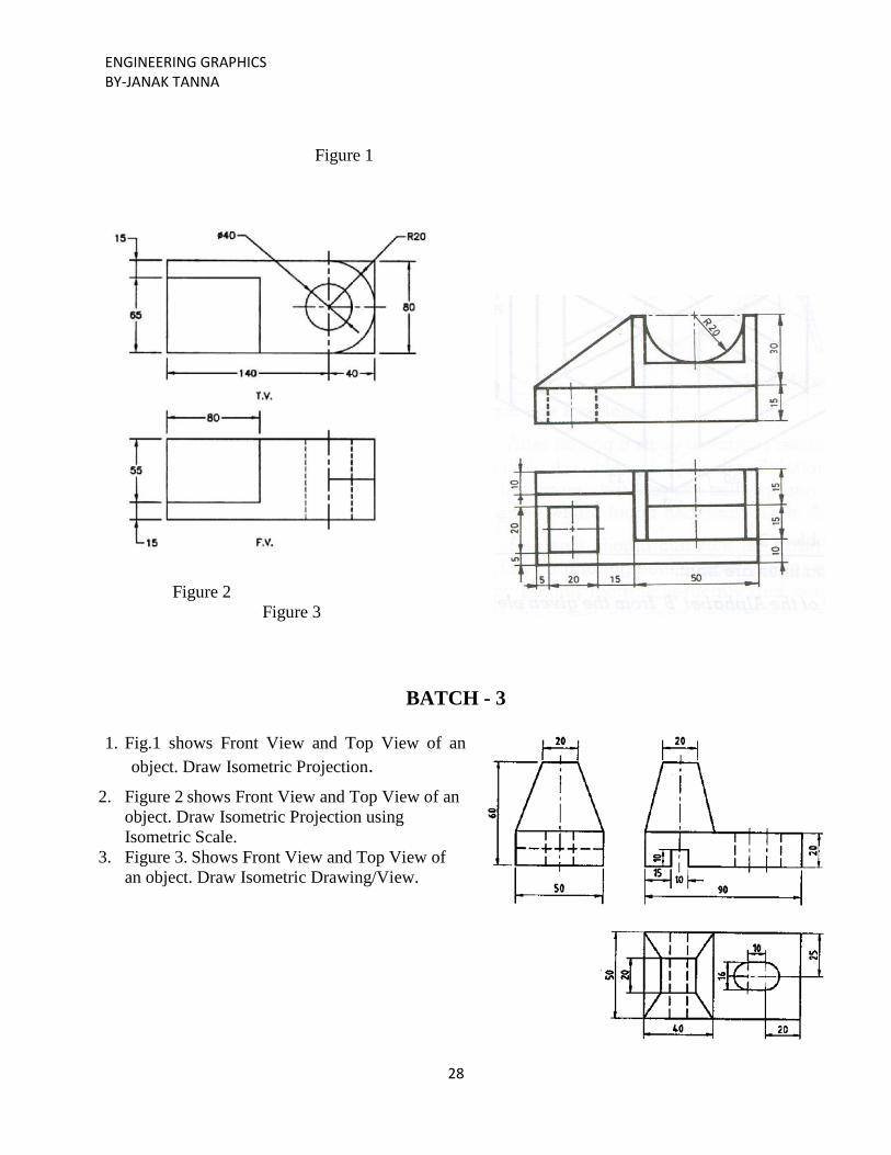
1. Fig.1 shows Front View and Top View of an
object. Draw Isometric Projection.
2. Figure 2 shows Front View and Top View of an
object. Draw Isometric Projection using
Isometric Scale.
3. Figure 3. Shows Front View and Top View of
an object. Draw Isometric Drawing/View.
Page 29
ENGINEERING GRAPHICS BY-JANAK TANNA
29
Figure 2 Figure 3
ASSIGNMENT
1. Draw the Isometric Projections of the object shown pictorially in Figure 1
Page 30
ENGINEERING GRAPHICS BY-JANAK TANNA
30
Figure 1
2. Figure 2. Shows Front View and Top View of an object. Draw Isometric Drawing/View.
3. Figure 3. Shows Front View and side View of an object. Draw Isometric Drawing/View.