Drawings have been used since the beginning of history for planning and producing art objects, architec- tural designs and engineering works. Since the Industrial Revolution a system for creating architectural and engineering drawings has evolved. While the pens, pencils, tools and papers for creating drawings have changed, the basic forms for presenting information have stayed the same. People doing technical work need to be familiar with the standard ways of presenting design information. Interpreting information from drawings is an important skill. Engineers and architects must be able to look at a set of plans and mentally picture the shapes of objects. Skilled workers must have the same abilities. Reading a drawing involves a highly developed ability to look at lines on the page and convert the shapes from several pictures to form a three-dimensional mental image. Concept Production Drawing Worker Introduction Chapter A Drawings Sketching Mechanical Drawing Computer Drawing Detail (Production) Drawing Assembly Drawing Thinking with a Pencil Tools Papers Measurements Computers and Networks Plotters Prototyping and Machining Engineering Graphics Introduction A - 1
Transcript
Drawings have been used since the beginning of history for planning and producing art objects, architec-tural designs and engineering works. Since the Industrial Revolution a system for creating architecturaland engineering drawings has evolved. While the pens, pencils, tools and papers for creating drawingshave changed, the basic forms for presenting information have stayed the same. People doing technicalwork need to be familiar with the standard ways of presenting design information.
Interpreting information from drawings is an important skill. Engineers and architects must be able tolook at a set of plans and mentally picture the shapes of objects. Skilled workers must have the sameabilities. Reading a drawing involves a highly developed ability to look at lines on the page and convertthe shapes from several pictures to form a three-dimensional mental image.
Concept ProductionDrawing
Worker
IntroductionChapter A
Drawings
Sketching
MechanicalDrawing
ComputerDrawing
Detail(Production)
Drawing
AssemblyDrawing
Thinkingwith aPencil
Tools Papers Measurements
Computersand
NetworksPlotters
Prototypingand
Machining
Engineering Graphics Introduction
A - 1
Production (Detail) Drawing
A Detail part or Working Drawing is shown.Features of the drawing include different viewsof the part, dimensions, notes, materials and atitle block. Drawings like this may be createdby manually drawing lines on paper or by com-puter. The drawing must convey all informa-tion needed to produce the part.
Learning to produce drawings like this in-volves knowing the rules for drawing views ofobjects, correct dimension choice and place-ment, correct format for drawing presentation.Many standards exist which tell how to pro-vide correct and consistent information tothose who use the drawings.
Reading drawings is the process of looking atthe lines that represent the part shapes andmentally picturing the part. This is a very high-level thinking process which requires practiceto become proficient.
A pictorialview gives
a quick ideaof the shapeof the part.
Multipleviews (Topand Frontin this ex-ample) are
used toshow the
true shapeof the
geometryof the part.
Introduction Engineering Graphics
A - 2
Assembly Drawings show the parts used, howthe parts are assembled and part identifications.Item numbers from the drawing are referencedin the Parts List or Bill of Materials. This is thefirst drawing in a set of drawings. It gives anoverview of the product and shows how theparts are used.
Assembly drawings are often included with theproduct for reference. An exploded view maybe used to identify parts for replacement and toshow how to dis-assemble and re-assemble forservicing.
Special instructions and notes are shown. Thesepertain to the whole assembly. Many compa-nies use PS or Process Specifications to specifyhow common jobs are to be performed. Inspec-tion, painting, packaging, etc. may be done inmany ways depending on the product. Refer-encing a PS-number is more efficient than writ-ing a lengthy note on the drawing.
Assembly Drawing
The Assembly Drawing is thefirst drawing in a set of drawings.
NOTES:1. INSPECT PER PS 1016
2. PAINT PER PS 58003. PACKAGE PER PS 9010
INSERT .005 SHIM BOTH SIDESTORQUE TO 9 FT. LB.REAM CENTER HOLE
.749/.750
Engineering Graphics Introduction
A - 3
SketchingFreehand sketches are used by designers totransfer mental images to paper. Ideas areconstantly changing as new thoughts occur.Engineers and architects create manysketches to help define the objects or con-structions they imagine. Meetings are held toexchange ideas, refine designs and get ap-provals to proceed with a design.
Words cannot describe three dimensionaltechnical design information accurately.Quick two dimensional or three dimensionalsketches clearly represent the shapes of ob-jects and the thoughts of the designers. Theability to sketch quickly and accurately toproportion is an important skill for all techni-cal workers.
Artistic ability is an asset but anyone canlearn to sketch by following basic tech-niques. Engineers and architects frequentlyuse special sketching grids which help keeplines straight and proportional.
All design information and research is ar-chived with drawings for each project. Thisis necessary for future use in case of failures,lawsuits or patent disputes as well as newprojects which grow from the current de-signs. Very clear, readable sketches and textinformation is essential.
Words and notes on sketches must be read-able. Experienced engineers and architectsuse block letters - usually uppercase - to as-sure clarity. Cursive writing is never used asit is often unreadable after sketches andmemos are duplicated or faxed to another lo-cation. Vertical capital block form letters arepreferred.
Rectangular sketching grid
Isometric (pictorial) sketching grid
PROPOSED RESIDENCE1625 MAIN STREET
Architectural StyleSlanted Letters
BEARING BLOCK DESIGNWITH REPLACEABLE INSERTS
Engineering style vertical capital letters.
Introduction Engineering Graphics
A - 4
Mechanical (Manual) DrawingComputer drawing has replaced most of themanual drawing work. Until 1985-1990 draw-ings were made on paper or other media usingtools.
.5MM fine lead pencils have become popularreplacing the the thicker wood and lead-holder type leads. Thicker leads are strongerbut require frequent sharpening. Lead hard-ness grades from 9H to H, F, HB to 6B areavailable. Select the lead hardness which suitsthe film or paper being used.
T-squares and drawing boards were used formany years to create accurate drawings. Paperor cloth material was aligned with the t-squareand held in place with tacks or tape. Skill wasrequired to keep all the tools in place whiledrawing.
Parallel rules running on string cables werepreferred by many architects. With care therules would maintain relatively accurate hori-zontal alignment. Metal or plastic 30-60 de-gree or 45-45 degree triangles were aligned todraw angles in 15 degree increments.
Drafting machines were popular for machinedrafting because the built in protractor allowedthe drawing of angles to the closest 5 minutesof one degree. Vertical and horizontal scalesreduced the need for triangles.
30-60 and 45-45 triangles are shown below.
Use white erasers for plasticfilm, pink for paper.
An AdjustableTriangle allowssettings to one
degree.
Engineering Graphics Introduction
A - 5
Manual Drafting Tools
Compass and dividerset. Locking com-pass helps to main-tain setting whilemaking very darklines.
Circle templates arebest for small diame-ter circles.
An erasing shieldhelps to do a cleanerjob of erasing. Eachtime the erasercrosses an edge, itcreates a fresh erasersurface.
Electric erasers areessential for largejobs.
Irregular curves areneeded when specialcurves must bedrawn.
Flexible curves maybe bent to preciseshapes.
Ink pens are used todraw very sharpblack lines.
Precise lettering maybe done using letter-ing guides. This is aslow process but itproduces nearly per-fect letter shapes.
Introduction Engineering Graphics
A - 6
Drawings may be created on paper or plastic film.Large drawings are duplicated by passing lightthrough the material to a copy sheet below. Draw-ing materials must pass light so translucent materi-als are used.
Drawing paper is a high quality paper with plas-tic coating. Vellum is a naturally transparent pa-per which was used before plastic coatings cameinto use.
Mylar film is a very stable, tough plastic filmwhich has a etched or coated drawing surface. My-lar is more expensive than paper but the stabilityand long term storage properties make it useful.Many hours of work and much information maybe involved on a single page so the expense is jus-tified.
Cloth drawings were used for many years. Thematerial was a very high quality linen with starchcoating. India ink was used to make the lines verydark. Many of these drawings are still in use.
Original drawings are carefully stored, often infireproof vaults. Copies are created and used forproduction and other purposes. Blueprinting is anolder process which required wet developers,washing and drying of the prints. Diazo is a newerprocess which creates dry prints right out of themachine. Diazo uses a print paper with a specialcoating. Once exposed to light the image is devel-oped using hot ammonia gas.
Drawing Sheet Sizes - USA Standard Inches
A = 8 1/2 x 11 or 9 x 12B = 11 x 17 or 12 x18C = 17 x 22 or 18 x 24D = 22 x 34 or 24 x 36E = 34 wide by 4’, 5’, 6’, etc.
GlassCylinder
MercuryVaporLight
Original
CopyLarge format digital printers and copiers are re-placing diazo process machines. Copies are moreexpensive but are sharper and longer lasting.
Drawing Papers - Copying Drawings
Engineering Graphics Introduction
A - 7
Measurements and Measuring ScalesMetric measurements are the world stand-ard. The United States has been slow tofully adopt the metric system. Most newautomobiles designs are done in metricwith a few of the older english measure-ment parts included.
Architectural construction is mostly eng-lish measurement based. Construction ma-terials like 2 x 4’s and 4 by 8 sheets ofplywood do not have easy to work withmetric equivalents. There is no great ur-gency to change.
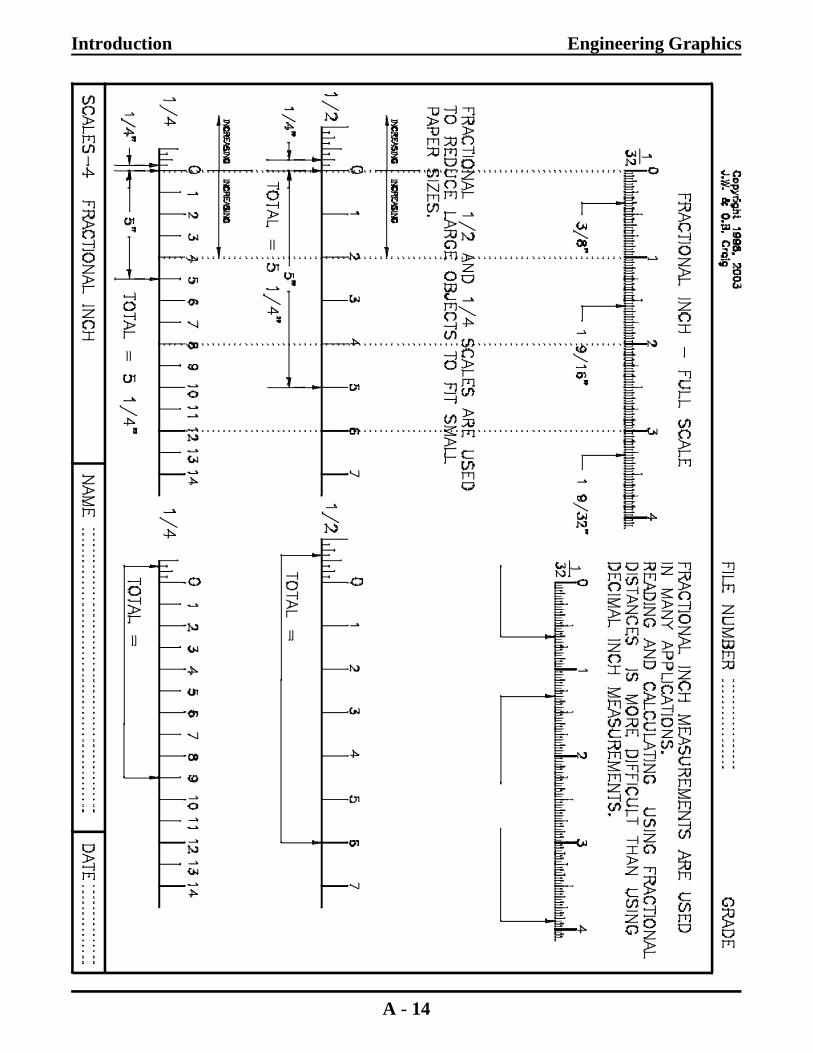
Fractional inch measurements are used forsome types of work and may be the meas-urement system used on older drawings.Reading fractional inch measurements maybe difficult for new users. Calculating withfractional measurements is a very complexprocess. Try dividing 7 23/32 by 9?
Decimal inch measurements are easier toread on scales and much easier to calculatewith. Metal decimal scales may have 100divisions per inch. Plastic scales and scalesprinted in this book will show only theeven hundredths.
Architectural measurements are composedof feet (base 12 with 12 inches to a foot)and inches (base 8,16,32 or 64 fractions toan inch). Calculating with feet, inches andfractions is also a very complex process.
Civil engineering units sometimes combinefeet, inches and decimal inches which sim-plifies calculations.
Drawings for large items on paper are cre-ated using reduced scales. A 1/4 " = 1’ -0"architectural scale is shown. Each 1/4" ismarked as a foot. Inches are shown to theleft of "0". Large constructions may beplaced on a small page using 1/4,1/8 or1/16scales.
Millimeters are commonly used forpart measurements.
(Examples are not drawn to scale).
Fractional inch measurements aredifficult to read and calculate.
Inches Feet
Computer drawings are created full size (1=1) onthe computer screen then reduced to fit the page
at plot time.
Decimal inch scale. Easier to read - easier to calculate
1/4" = 1’ - 0" Architectural scale
Introduction Engineering Graphics
A - 8
Computer Drawing and ModelingIBM introduced the powerful and relatively in-expensive IBM-PC around 1983. AutoCAD in-troduced a usable drafting software program in1984. AutoCAD emulated the paper drawingprocess using constructions and drawing proc-esses similar to the way work was done on pa-per. Early computers used black and whitemonitors. It would be several years before themouse became popular as a pointing device.
Industry quickly adopted computer drawing.The change from manual drafting to computerdrafting was far faster than the change fromtypewriters to word processors in business.Computer drawings took about the same amountof time to create as manual drawings but thetime savings in revising and updating drawingswas a significant benefit. 2D drawings were cre-ated one line, one circle, etc. at a time just likeon paper.
Computer networks provided quick access tostored files and fast exchange of information be-tween designers.
Faster computers with better graphics and largercore memory have made possible the use ofnewer software which changes the drawing proc-ess. Three dimensional modeling allows the de-signer to work with solid images which areidentical to the finished part. Once the 3D im-age is finished the process of creating the 2Dworking drawings requires only a few mouseclicks. 2D drawings which once took hours ordays to complete now only take minutes to com-plete. Modeling mating parts reduces thechance of error when parts do not line up or fitproperly.
Engineers and architects are able to transfer 3Dmental images quickly and accurately to thecomputer screen. View controls allow the rota-tion of parts to better analyze the shape and criti-cal elements of each design.
2D multiple viewdrawings are pro-duced with only afew mouse clicks.
Engineering Graphics Introduction
A - 9
Computer drawings are plotted to stand-ard size title block sheets. Early plottersdrew lines using ink pens. This processproduced accurate drawings but the pensskipped or ran out of ink at times.Newer plotters use ink-jet or laser print-ing processes which have fewer me-chanical problems.
CAD/CAM is a process of taking 3Dmodeling data from the computer andconverting it directly into machine toolcontrol statements. It is possible to de-sign a part and machine the part withina few minutes. Parts which used totake days to produce now take onlyminutes.
Rapid Prototyping.
One Stereolithography process buildsparts in liquid polymer by fusing thepolymer using ultraviolet light createdby focused laser beams.