ENGINEERING INFORMATION SPUR GEARS GEAR NOMENCLATURE ADDENDUM (a) is the height by which a tooth projects beyond the pitch circle or pitch line. BASE DIAMETER (D b ) is the diameter of the base cylinder from which the involute portion of a tooth profile is generated. BACKLASH (B) is the amount by which the width of a tooth space exceeds the thickness of the engaging tooth on the pitch circles. As actually indicated by measuring devices, backlash may be determined variously in the transverse, nor- mal, or axial-planes, and either in the direction of the pitch cir- cles or on the line of action. Such measurements should be corrected to corresponding values on transverse pitch circles for general comparisons. BORE LENGTH is the total length through a gear, sprocket, or coupling bore. CIRCULAR PITCH (p) is the distance along the pitch circle or pitch line between corresponding profiles of adjacent teeth. CIRCULAR THICKNESS (t) is the length of arc between the two sides of a gear tooth on the pitch circle, unless otherwise specified. CLEARANCE-OPERATING (c) is the amount by which the dedendum in a given gear exceeds the addendum of its mat- ing gear. CONTACT RATIO (m c ) in general, the number of angular pitches through which a tooth surface rotates from the begin- ning to the end of contact. DEDENDUM (b) is the depth of a tooth space below the pitch line. It is normally greater than the addendum of the mating gear to provide clearance. DIAMETRAL PITCH (P) is the ratio of the number of teeth to the pitch diameter. FACE WIDTH (F) is the length of the teeth in an axial plane. FILLET RADIUS (r f ) is the radius of the fillet curve at the base of the gear tooth. FULL DEPTH TEETH are those in which the working depth equals 2.000 divided by the normal diametral pitch. GEAR is a machine part with gear teeth. When two gears run together, the one with the larger number of teeth is called the gear. HUB DIAMETER is outside diameter of a gear, sprocket or coupling hub. HUB PROJECTION is the distance the hub extends beyond the gear face. INVOLUTE TEETH of spur gears, helical gears and worms are those in which the active portion of the profile in the trans- verse plane is the involute of a circle. LONG- AND SHORT-ADDENDUM TEETH are those of engaging gears (on a standard designed center distance) one of which has a long addendum and the other has a short addendum. KEYWAY is the machined groove running the length of the bore. A similar groove is machined in the shaft and a key fits into this opening. NORMAL DIAMETRAL PITCH (P n ) is the value of the diametral pitch as calculated in the normal plane of a helical gear or worm. NORMAL PLANE is the plane normal to the tooth surface at a pitch point and perpendicular to the pitch plane. For a helical gear this plane can be normal to one tooth at a point laying in the plane surface. At such point, the normal plane contains the line normal to the tooth surface and this is normal to the pitch circle. NORMAL PRESSURE ANGLE (ø n ) in a normal plane of heli- cal tooth. OUTSIDE DIAMETER (D o ) is the diameter of the addendum (outside) circle. Gear Catalog 137
ADDENDUM (a) is the height by which a tooth projects beyond the pitch circle or pitch line.
BASE DIAMETER (Db) is the diameter of the base cylinder from which the involute portion of a tooth profile is generated.
BACKLASH (B) is the amount by which the width of a tooth space exceeds the thickness of the engaging tooth on the pitch circles. As actually indicated by measuring devices, backlash may be determined variously in the transverse, normal, or axial-planes, and either in the direction of the pitch circles or on the line of action. Such measurements should be corrected to corresponding values on transverse pitch circles for general comparisons.
BORE LENGTH is the total length through a gear, sprocket, or coupling bore.
CIRCULAR PITCH (p) is the distance along the pitch circle or pitch line between corresponding profiles of adjacent teeth.
CIRCULAR THICKNESS (t) is the length of arc between the two sides of a gear tooth on the pitch circle, unless otherwise specified.
CLEARANCE-OPERATING (c) is the amount by which the dedendum in a given gear exceeds the addendum of its mating gear.
CONTACT RATIO (mc) in general, the number of angular pitches through which a tooth surface rotates from the beginning to the end of contact.
DEDENDUM (b) is the depth of a tooth space below the pitch line. It is normally greater than the addendum of the mating gear to provide clearance.
DIAMETRAL PITCH (P) is the ratio of the number of teeth to the pitch diameter.
FACE WIDTH (F) is the length of the teeth in an axial plane.
FILLET RADIUS (rf) is the radius of the fillet curve at the base of the gear tooth.
FULL DEPTH TEETH are those in which the working depth equals 2.000 divided by the normal diametral pitch.
GEAR is a machine part with gear teeth. When two gears run together, the one with the larger number of teeth is called the gear.
HUB DIAMETER is outside diameter of a gear, sprocket or coupling hub.
HUB PROJECTION is the distance the hub extends beyond the gear face.
INVOLUTE TEETH of spur gears, helical gears and worms are those in which the active portion of the profile in the trans-verse plane is the involute of a circle.
LONG- AND SHORT-ADDENDUM TEETH are those of engaging gears (on a standard designed center distance) one of which has a long addendum and the other has a short addendum.
KEYWAY is the machined groove running the length of the bore. A similar groove is machined in the shaft and a key fits into this opening.
NORMAL DIAMETRAL PITCH (Pn) is the value of the diametral pitch as calculated in the normal plane of a helical gear or worm.
NORMAL PLANE is the plane normal to the tooth surface at a pitch point and perpendicular to the pitch plane. For a helical gear this plane can be normal to one tooth at a point laying in the plane surface. At such point, the normal plane contains the line normal to the tooth surface and this is normal to the pitch circle.
NORMAL PRESSURE ANGLE (øn) in a normal plane of helical tooth.
OUTSIDE DIAMETER (Do) is the diameter of the addendum (outside) circle.
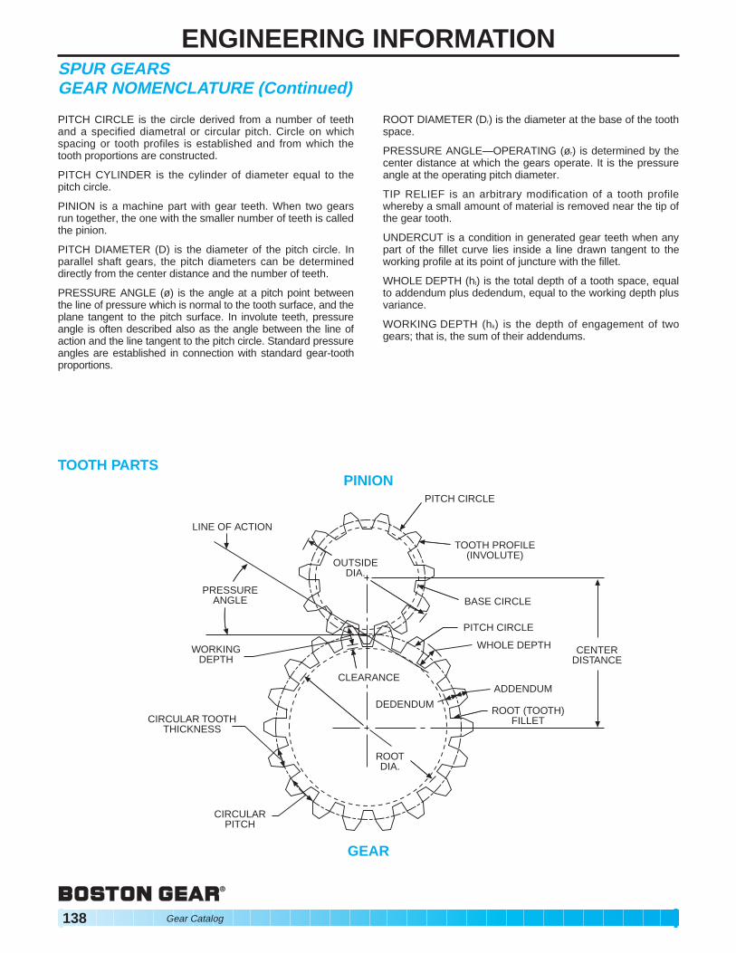
PITCH CIRCLE is the circle derived from a number of teeth and a specified diametral or circular pitch. Circle on which spacing or tooth profiles is established and from which the tooth proportions are constructed.
PITCH CYLINDER is the cylinder of diameter equal to the pitch circle.
PINION is a machine part with gear teeth. When two gears run together, the one with the smaller number of teeth is called the pinion.
PITCH DIAMETER (D) is the diameter of the pitch circle. In parallel shaft gears, the pitch diameters can be determined directly from the center distance and the number of teeth.
PRESSURE ANGLE (ø) is the angle at a pitch point between the line of pressure which is normal to the tooth surface, and the plane tangent to the pitch surface. In involute teeth, pressure angle is often described also as the angle between the line of action and the line tangent to the pitch circle. Standard pressure angles are established in connection with standard gear-tooth proportions.
TOOTH PARTS
ROOT DIAMETER (Dr) is the diameter at the base of the tooth space.
PRESSURE ANGLE—OPERATING (ør) is determined by the center distance at which the gears operate. It is the pressure angle at the operating pitch diameter.
TIP RELIEF is an arbitrary modification of a tooth profile whereby a small amount of material is removed near the tip of the gear tooth.
UNDERCUT is a condition in generated gear teeth when any part of the fillet curve lies inside a line drawn tangent to the working profile at its point of juncture with the fillet.
WHOLE DEPTH (ht) is the total depth of a tooth space, equal to addendum plus dedendum, equal to the working depth plus variance.
WORKING DEPTH (hk) is the depth of engagement of two gears; that is, the sum of their addendums.
PINION PITCH CIRCLE
CIRCULAR PITCH
CIRCULAR TOOTH THICKNESS
WORKING DEPTH
PRESSURE ANGLE
LINE OF ACTION
OUTSIDE DIA.
TOOTH PROFILE (INVOLUTE)
BASE CIRCLE
PITCH CIRCLE
WHOLE DEPTH
ADDENDUM
ROOT DIA.
DEDENDUM
CLEARANCE
ROOT (TOOTH) FILLET
CENTER DISTANCE
GEAR
138 Gear Catalog
ENGINEERING INFORMATIONSPUR GEARS INVOLUTE FORM
Gear teeth could be manufactured with a wide variety of shapes and profiles. The involute profile is the most commonly used system for gearing today, and all Boston spur and helical gears are of involute form.
An involute is a curve that is traced by a point on a taut cord unwinding from a circle, which is called a BASE CIRCLE. The involute is a form of spiral, the curvature of which becomes straighter as it is drawn from a base circle and eventually would become a straight line if drawn far enough.
An involute drawn from a larger base circle will be less curved (straighter) than one drawn from a smaller base circle. Similarly, the involute tooth profile of smaller gears is consider-ably curved, on larger gears is less curved (straighter), and is straight on a rack, which is essentially an infinitely large gear.
C IR C L E B
CIR
CLE A
INVOLUTE – CIRCLE
B
INVOLUTE – CIRCLE A
Involute gear tooth forms and standard tooth proportions are specified in terms of a basic rack which has straight-sided teeth, for involute systems.
20 TEETH 48 TEETH RACK
Gear Catalog 139
ENGINEERING INFORMATIONSPUR GEARS
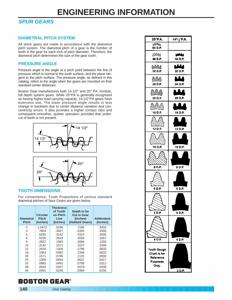
DIAMETRAL PITCH SYSTEM All stock gears are made in accordance with the diametral pitch system. The diametral pitch of a gear is the number of teeth in the gear for each inch of pitch diameter. Therefore, the diametral pitch determines the size of the gear tooth.
PRESSURE ANGLE Pressure angle is the angle at a pitch point between the line of pressure which is normal to the tooth surface, and the plane tan-gent to the pitch surface. The pressure angle, as defined in this catalog, refers to the angle when the gears are mounted on their standard center distances.
Boston Gear manufactures both 14-1/2° and 20° PA, involute, full depth system gears. While 20°PA is generally recognized as having higher load carrying capacity, 14-1/2°PA gears have extensive use. The lower pressure angle results in less change in backlash due to center distance variation and con-centricity errors. It also provides a higher contact ratio and consequent smoother, quieter operation provided that under-cut of teeth is not present.
TOOTH DIMENSIONS For convenience, Tooth Proportions of various standard diametral pitches of Spur Gears are given below.
An increase or decrease in center distance will cause an increase or decrease in backlash. Since, in practice, some deviation from the theoretical standard center distance is inevitable and will alter the backlash, such deviation should be as small as possible. For most applications, it would be acceptable to limit the deviation to an increase over the nominal center distance of one half the aver-age backlash. Varying the center distance may afford a practical means of varying the backlash to a limited extent. The approximate relationship between center distance and backlash change of 14-1/2° and 20° pressure angle gears is shown below: For 14-1/2°–Change in Center Distance = 1.933 x Change in Backlash For 20° –Change in Center Distance = 1.374 x Change in Backlash From this, it is apparent that a given change in center distance, 14-1/2° gears will have a smaller change in backlash than 20° gears. This fact should be considered in cases where backlash is critical.
UNDERCUT When the number of teeth in a gear is small, the tip of the mating gear tooth may interfere with the lower portion of the tooth pro-file. To prevent this, the generating process removes material at this point. This results in loss of a portion of the involute adjacent to the tooth base, reducing tooth contact and tooth strength. On 14-1/2°PA gears undercutting occurs where a number of teeth is less than 32 and for 20°PA less than 18. Since this condition becomes more severe as tooth numbers decrease, it is recommended that the minimum number of teeth be 16 for 14-1/2°PA and 13 for 20°PA. In a similar manner INTERNAL Spur Gear teeth may interfere when the pinion gear is too near the size of its mating internal gear. The following may be used as a guide to assure proper operation of the gear set. For 14-1/2°PA, the difference in tooth numbers between the gear and pinion should not be less than 15. For 20°PA the difference in tooth numbers should not be less than 12.
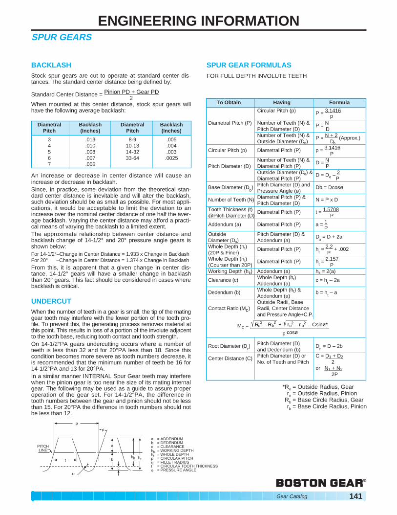
PITCH LINE
p
a
b
c rf
t hk ht
è
a = ADDENDUM b = DEDENDUM c = CLEARANCE hk = WORKING DEPTH ht = WHOLE DEPTH p = CIRCULAR PITCH rf = FILLET RADIUS
= CIRCULAR TOOTH THICKNESS
SPUR GEAR FORMULAS FOR FULL DEPTH INVOLUTE TEETH
To Obtain Having Formula
Circular Pitch (p) P = 3.1416 p
Diametral Pitch (P) Number of Teeth (N) & P = N Pitch Diameter (D) D Number of Teeth (N) & P = N + 2 (Approx.)Outside Diameter (Do) Do
Circular Pitch (p) Diametral Pitch (P) p = 3.1416P
Number of Teeth (N) & D = N Pitch Diameter (D) Diametral Pitch (P) P
Outside Diameter (Do) & D = Do – 2 Diametral Pitch (P) P
Base Diameter (Db) Pitch Diameter (D) and Db = Dcosø
Pressure Angle (ø)
Number of Teeth (N) Diametral Pitch (P) & N = P x DPitch Diameter (D)
Tooth Thickness (t) Diametral Pitch (P) t = 1.5708 @Pitch Diameter (D) P
Addendum (a) Diametral Pitch (P) a = 1 P
Outside Pitch Diameter (D) & D o
= D + 2aDiameter (Do) Addendum (a) Whole Depth (ht) Diametral Pitch (P) h
t = 2.2 + .002
(20P & Finer) P Whole Depth (ht) Diametral Pitch (P) h
t = 2.157
(Courser than 20P) P Working Depth (hk) Addendum (a) hk = 2(a)
Clearance (c) Whole Depth (ht) c = h t– 2a
Addendum (a)
Dedendum (b) Whole Depth (ht) & b = h t – a
Addendum (a) Outside Radii, Base
Contact Ratio (Mc) Radii, Center Distance and Pressure Angle+C.P.
Root Diameter (Dr) Pitch Diameter (D) D
r= D – 2b
and Dedendum (b)
Center Distance (C) Pitch Diameter (D) or C = D1 + D2 No. of Teeth and Pitch 2
Rb = Base Circle Radius, Gear rb = Base Circle Radius, Pinion
tè = PRESSURE ANGLE
Gear Catalog 141
ENGINEERING INFORMATIONSPUR GEARS
LEWIS FORMULA (Barth Revision) Gear failure can occur due to tooth breakage (tooth stress) or surface failure (surface durability) as a result of fatigue and wear. Strength is determined in terms of tooth-beam stresses for static and dynamic conditions, following well established formula and procedures. Satisfactory results may be obtained by the use of Barth’s Revision to the Lewis Formula, which considers beam strength but not wear. The formula is satisfactory for commercial gears at Pitch Circle velocities of up to 1500 FPM. It is this formula that is the basis for all Boston Spur Gear ratings. METALLIC SPUR GEARS
W = SFY 600 + V
600 P
W= Tooth Load, Lbs. (along the Pitch Line)S = Safe Material Stress (static) Lbs. per Sq. In. (Table II)F = Face Width, In.Y = Tooth Form Factor (Table I)P = Diametral PitchD = Pitch DiameterV = Pitch Line Velocity, Ft. per Min. = .262 x D x RPMFor NON-METALLIC GEARS, the modified Lewis Formulashown below may be used with (S) values of 6000 PSI forPhenolic Laminated material.
W = SFY 200 + V
150 + .25 P
TABLE II–VALUES OF SAFE STATIC STRESS (s)
Max. allowable torque (T) that should be imposed on a gear
will be the safe tooth load (W) multiplied by D or T = W x D 2 2
The safe horsepower capacity of the gear (at a given RPM) can
be calculated from HP = T x RPM or directly from (W) and (V);63,025
HP = WV 33,000
For a known HP, T = 63025 x HP RPM
Material (s) Lb. per Sq. In. Plastic ........................................................................ 5000 Bronze ........................................................................ 10000 Cast Iron ..................................................................... 12000
GEAR NOMENCLATURE The information contained in the Spur Gear section is also pertinent to Helical Gears with the addition of the following: HELIX ANGLE (ë) is the angle between any helix and an element of its cylinder. In helical gears, it is at the pitch diameter unless otherwise specified. LEAD (L) is the axial advance of a helix for one complete turn, as in the threads of cylindrical worms and teeth of helical gears. NORMAL DIAMETRAL PITCH (Pn) is the Diametral Pitch as calculated in the normal plane. HAND – Helical Gears of the same hand operate at right
angles, see Fig. 1 Helical Gears of opposite hands run on parallel shafts. Fig. 2
TWO TWO LEFT-HAND AND RIGHT-HAND LEFT-HAND RIGHT-HAND
HELICAL GEARS HELICAL GEARS HELICAL GEARS
Figure 1 Figure 2
LEFT HAND HELICAL GEAR RIGHT HAND HELICAL GEAR
The teeth of a LEFT HAND The teeth of a RIGHT HAND Helical Gear lean to the left Helical Gear lean to the right when the gear is placed flat on when the gear is placed flat on a horizontal surface. a horizontal surface.
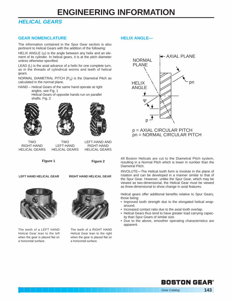
HELIX ANGLE—
pn
AXIAL PLANE NORMAL PLANE
HELIX ANGLE
p
{
p = AXIAL CIRCULAR PITCH pn = NORMAL CIRCULAR PITCH
All Boston Helicals are cut to the Diametral Pitch system, resulting in a Normal Pitch which is lower in number than the Diametral Pitch.
INVOLUTE—The Helical tooth form is involute in the plane of rotation and can be developed in a manner similar to that of the Spur Gear. However, unlike the Spur Gear, which may be viewed as two-dimensional, the Helical Gear must be viewed as three-dimensional to show change in axial features.
Helical gears offer additional benefits relative to Spur Gears, those being: • Improved tooth strength due to the elongated helical wrap-
around. • Increased contact ratio due to the axial tooth overlap. • Helical Gears thus tend to have greater load carrying capac
ity than Spur Gears of similar size. • Due to the above, smoother operating characteristics are
apparent.
Gear Catalog 143
ENGINEERING INFORMATIONHELICAL GEARS
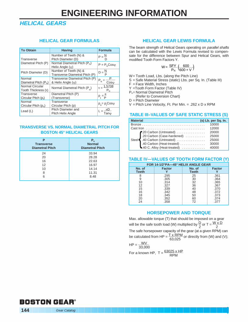
HELICAL GEAR FORMULAS
TRANSVERSE VS. NORMAL DIAMETRAL PITCH FOR BOSTON 45° HELICAL GEARS
Pitch Diameter (D) Number of Teeth (N) & Transverse Diametral Pitch (P)
D = N P
Normal Diametral Pitch (PN)
Transverse Diametral Pitch (P) & Helix Angle (ë)
PN = P Cosë
Normal Circular Tooth Thickness (ç)
Normal Diametral Pitch (PN) ç = 1.5708
PN
Transverse Circular Pitch (pt)
Diametral Pitch (P) (Transverse)
p t = L
P Normal Circular Pitch (pn)
Transverse Circular Pitch (p)
pn= p
t Cosë
Lead (L) Pitch Diameter and Pitch Helix Angle
L = LD Tanë
HELICAL GEAR LEWIS FORMULA The beam strength of Helical Gears operating on parallel shafts can be calculated with the Lewis Formula revised to compensate for the difference between Spur and Helical Gears, with modified Tooth Form Factors Y.
W = SFY 600 + V
600 PN
W= Tooth Load, Lbs. (along the Pitch Line)S = Safe Material Stress (static) Lbs. per Sq. In. (Table III)F = Face Width, InchesY =Tooth Form Factor (Table IV)PN= Normal Diametral Pitch
(Refer to Conversion Chart) D = Pitch Diameter V = Pitch Line Velocity, Ft. Per Min. = .262 x D x RPM
HORSEPOWER AND TORQUE Max. allowable torque (T) that should be imposed on a gear
will be the safe tooth load (W) multiplied by D or T = W x D 2 2
The safe horsepower capacity of the gear (at a given RPM) can
be calculated from HP = T x RPM or directly from (W) and (V);63,025
HP = WV 33,000
For a known HP, T = 63025 x HP RPM
144 Gear Catalog
ENGINEERING INFORMATIONHELICAL GEARS
When Helical gears are operated on other than Parallel shafts, the tooth load is concentrated at a point, with the result that very small loads produce very high pressures. The sliding velocity is usually quite high and, combined with the concentrated pressure, may cause galling or excessive wear, especially if the teeth are not well lubricated. For these reasons, the tooth load which may be applied to such drives is very limited and of uncertain value, and is perhaps best determined by trial under actual operating conditions. If one of the gears is made of bronze, the contact area and thereby the load carrying capacity, may be increased, by allowing the gears to “run-in” in their operating position, under loads which gradually increase to the maximum expected.
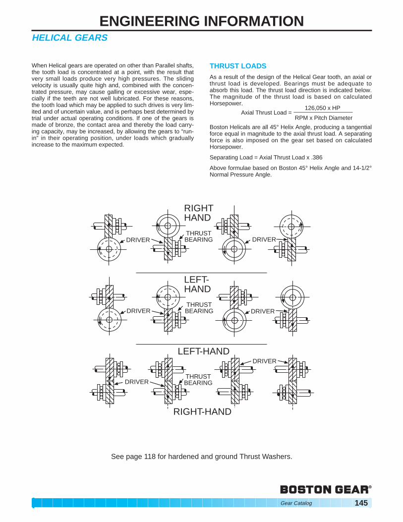
THRUST LOADS As a result of the design of the Helical Gear tooth, an axial or thrust load is developed. Bearings must be adequate to absorb this load. The thrust load direction is indicated below. The magnitude of the thrust load is based on calculated Horsepower.
126,050 x HPAxial Thrust Load =
RPM x Pitch Diameter
Boston Helicals are all 45° Helix Angle, producing a tangential force equal in magnitude to the axial thrust load. A separating force is also imposed on the gear set based on calculated Horsepower.
Separating Load = Axial Thrust Load x .386
Above formulae based on Boston 45° Helix Angle and 14-1/2° Normal Pressure Angle.
RIGHT HAND
THRUST DRIVER BEARING DRIVER
LEFT-HAND
THRUST BEARING DRIVERDRIVER
DRIVER THRUST BEARING
LEFT-HAND
RIGHT-HAND
DRIVER
See page 118 for hardened and ground Thrust Washers.
Gear Catalog 145
ENGINEERING INFORMATIONMITER AND BEVEL GEARS
Gear geometry for both straight and spiral tooth Miter and Bevel gears is of a complex nature and this text will not attempt to cover the topic in depth.
The basic tooth form is a modification to the involute form and is the common form used in production today. All Boston standard stock Miter and Bevel gears are manufactured with a 20° Pressure Angle. Bevel gears are made in accordance with A.G.M.A. specifications for long and short Addendum system for gears and pinions (pinion is cut long Addendum) which serves to reduce the amount of pinion tooth undercut and to nearly equalize the strength and durability of the gear set.
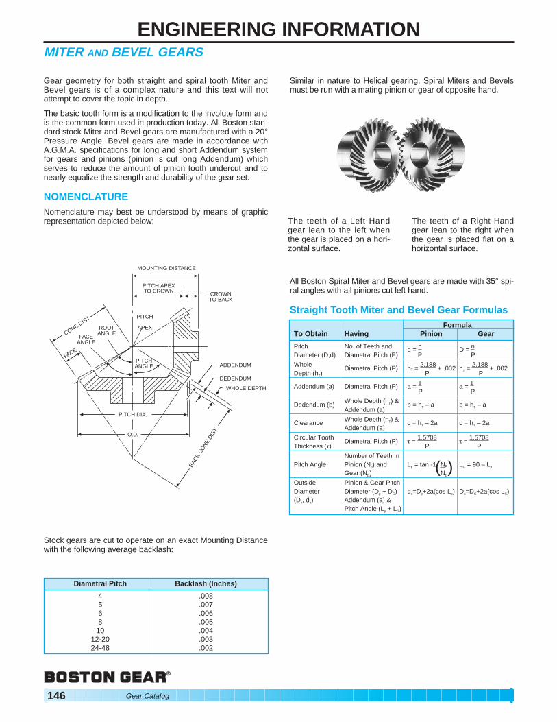
NOMENCLATURE Nomenclature may best be understood by means of graphic representation depicted below:
MOUNTING DISTANCE
ADDENDUM
DEDENDUM
WHOLE DEPTH
CROWN TO BACK
PITCH APEX TO CROWN
PITCH
APEX ROOT ANGLE
PITCH ANGLE
PITCH DIA.
O.D.
FACE ANGLE
FACE
CONE DIST
BAC
K C
ON
E D
IST
Stock gears are cut to operate on an exact Mounting Distance with the following average backlash:
Similar in nature to Helical gearing, Spiral Miters and Bevels must be run with a mating pinion or gear of opposite hand.
The teeth of a Left Hand The teeth of a Right Hand gear lean to the left when gear lean to the right when the gear is placed on a hori- the gear is placed flat on a zontal surface. horizontal surface.
All Boston Spiral Miter and Bevel gears are made with 35° spiral angles with all pinions cut left hand.
Straight Tooth Miter and Bevel Gear Formulas Formula
To Obtain Having Pinion Gear
Pitch No. of Teeth and d = n D = n Diameter (D,d) Diametral Pitch (P) P P
Whole Diametral Pitch (P) hT = 2.188 + .002 hT = 2.188 + .002 Depth (hT) P P
Addendum (a) Diametral Pitch (P) a = 1 a = 1 P P
Dedendum (b) Whole Depth (hT) & b = hT – a b = hT – a Addendum (a)
Clearance Whole Depth (nT) & c = hT – 2a c = hT – 2a Addendum (a)
Straight tooth bevel (and miter) gears are cut with generated tooth form having a localized lengthwise tooth bearing known as the “Coniflex”® tooth form. The superiority of these gears over straight bevels with full length tooth bearing, lies in the control of tooth contact. The localization of contact permits minor adjustment of the gears in assembly and allows for some displacement due to deflection under operating loads, without concentration of the load on the end of the tooth. This results in increased life and quieter operation.
PINION APEX ON CENTER
TOOTH BEARING CENTRAL
PINION APEX DEFLECTED OR ASSEMBLED OFF
CENTER
TOOTH BEARING SHIFTED OFF CENTER
BUT STILL SAFE
(A) (B)
ILLUSTRATION OF LOCALIZED TOOTH BEARING IN STRAIGHT BEVEL CONIFLEX® GEARS
Boston Gear Bevel and Miter Gears will provide smooth, quiet operation and long life when properly mounted and lubricated. There are several important considerations in mounting these gears.
1. All standard stock bevel and miter gears must be mounted at right angles (90°) for proper tooth bearing.
2. Mounting Distance (MD) is the distance from the end of the hub of one gear to the center line of its mating gear. When mounted at the MD specified, the gears will have a proper backlash and the ends of the gear teeth will be flush with each other (see drawings).
3. All bevel and miter gears develop radial and axial thrust loads when transmitting power. See page 148. These loads must be accommodated by the use of bearings.
MOUNTING DISTANCE
Incorrect If Mounting Distance of one or both gears is made less than dimension specified, the teeth may bind. Excessive wear or breakage can result. Drawing below shows gears mounted incorrectly with the Mounting Distance too short for one gear.
MOUNTING DISTANCE
TOO SMALL
Incorrect If Mounting Distance of either gear is made longer than dimension specified, as shown in drawing below, the gears will not be in full mesh on a common pitch line and may have excessive backlash. Excessive backlash or play, if great enough, can cause a sudden impulse or shock load in starting or reversing which might cause serious tooth damage.
MOUNTING DISTANCE
TOO GREAT
MOUNTING
MOUNTING DISTANCE MOUNTING
DISTANCE
DISTANCE
®Registered in the U.S. Patent Office.
Gear Catalog 147
ENGINEERING INFORMATIONMITER AND BEVEL BEARSTOOTH STRENGTH (Straight Tooth)
The beam strength of Miter and Bevel gears (straight tooth) may be calculated using the Lewis Formula revised to compensate for the differences between Spur and Bevel gears. Several factors are often combined to make allowance for the tooth taper and the normal overhung mounting of Bevel gears.
W = SFY 600 + V
600 .75 P
W = Tooth Load, Lbs. (along the Pitch Line)S = Safe Material Stress (static) Lbs. per Sq. In. (Table 1)F = Face Width, In.Y = Tooth Form Factor (Table I)P = Diametral PitchD = Pitch DiameterV = Pitch Line Velocity, Ft. per Min. = .262 x D x RPM
TABLE I VALUES OF SAFE STATIC STRESS (s)
TABLE II TOOTH FORM FACTOR (Y) 20°P.A.—LONG ADDENDUM PINIONS SHORT ADDENDUM GEARS
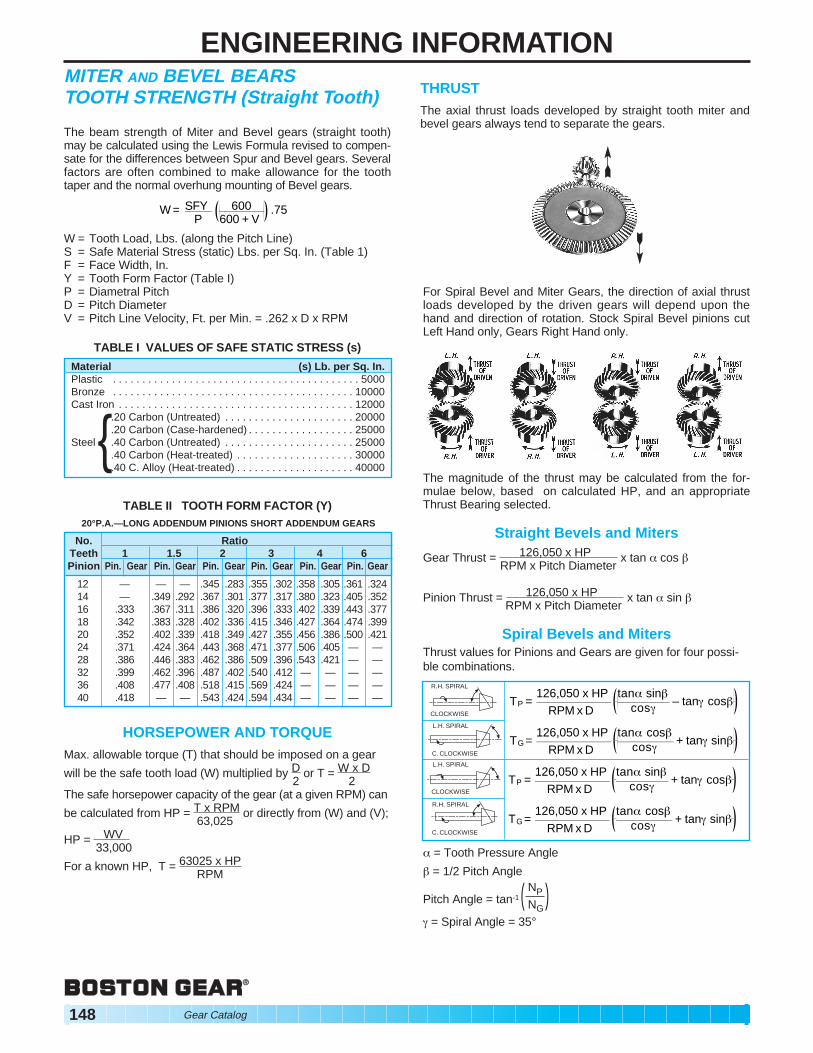
THRUST The axial thrust loads developed by straight tooth miter and bevel gears always tend to separate the gears.
For Spiral Bevel and Miter Gears, the direction of axial thrust loads developed by the driven gears will depend upon the hand and direction of rotation. Stock Spiral Bevel pinions cut Left Hand only, Gears Right Hand only.
The magnitude of the thrust may be calculated from the formulae below, based on calculated HP, and an appropriate Thrust Bearing selected.
Straight Bevels and Miters
Gear Thrust = 126,050 x HP RPM x Pitch Diameter
x tan | cos }
Pinion Thrust = 126,050 x HP RPM x Pitch Diameter
x tan | sin }
Spiral Bevels and Miters Thrust values for Pinions and Gears are given for four possible combinations.
TG = 126,050 x HP
RPM x D tan| cos}
cos~ + tan~ sin}
TP = 126,050 x HP
RPM x D tan| sin}
cos~ + tan~ cos}
TG = 126,050 x HP
RPM x D tan| cos}
cos~ + tan~ sin}
TP = 126,050 x HP
RPM x D tan| sin}
cos~ – tan~ cos}
R.H. SPIRAL
CLOCKWISE
L.H. SPIRAL
C. CLOCKWISE
CLOCKWISE
L.H. SPIRAL
R.H. SPIRAL
C. CLOCKWISE
| = Tooth Pressure Angle
} = 1/2 Pitch Angle
Pitch Angle = tan-1 ( NP )NG
~ = Spiral Angle = 35°
148 Gear Catalog
ENGINEERING INFORMATIONWORMS AND WORM GEARS
Boston standard stock Worms and Worm Gears are used for the transmission of motion and/or power between non-intersecting shafts at right angles (90°). Worm Gear drives are considered the smoothest and quietest form of gearing when properly applied and maintained. They should be considered for the following requirements:
HIGH RATIO SPEED REDUCTION LIMITED SPACE RIGHT ANGLE (NON-INTERSECTING) SHAFTS GOOD RESISTANCE TO BACK DRIVING
General nomenclature having been applied to Spur and Helical gear types, may also be applied to Worm Gearing with the addition of Worm Lead and Lead Angle, Number of Threads (starts) and Worm Gear Throat diameter.
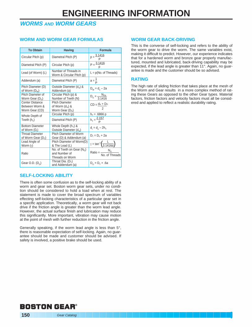
HOW TO TELL A LEFT-HANDOR RIGHT-HAND
WORM OR WORM GEAR
Threads of LEFT-HAND lean to the Left when standing on either end:
Threads of RIGHT-HAND lean to the Right when standing on either end:
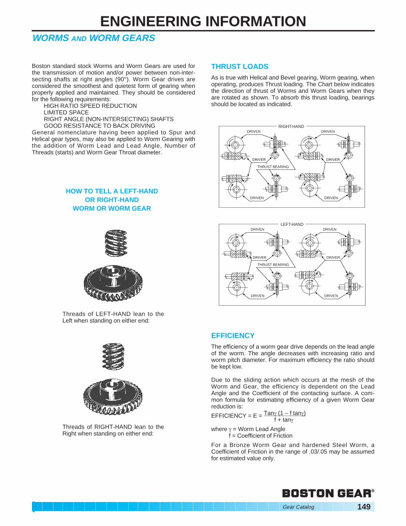
THRUST LOADS As is true with Helical and Bevel gearing, Worm gearing, when operating, produces Thrust loading. The Chart below indicates the direction of thrust of Worms and Worm Gears when they are rotated as shown. To absorb this thrust loading, bearings should be located as indicated.
DRIVER
THRUST BEARING
DRIVEN
DRIVEN
DRIVER
DRIVEN
DRIVEN RIGHT-HAND
DRIVER
THRUST BEARING
DRIVEN
DRIVEN
DRIVER
DRIVEN
DRIVEN LEFT-HAND
EFFICIENCY The efficiency of a worm gear drive depends on the lead angle of the worm. The angle decreases with increasing ratio and worm pitch diameter. For maximum efficiency the ratio should be kept low.
Due to the sliding action which occurs at the mesh of the Worm and Gear, the efficiency is dependent on the Lead Angle and the Coefficient of the contacting surface. A common formula for estimating efficiency of a given Worm Gear reduction is:
EFFICIENCY = E = Tan~ (1 – f tan~) f + tan~
where ~ = Worm Lead Angle f = Coefficient of Friction
For a Bronze Worm Gear and hardened Steel Worm, a Coefficient of Friction in the range of .03/.05 may be assumed for estimated value only.
Gear Catalog 149
ENGINEERING INFORMATIONWORMS AND WORM GEARS
WORM AND WORM GEAR FORMULAS
SELF-LOCKING ABILITY There is often some confusion as to the self-locking ability of a worm and gear set. Boston worm gear sets, under no condition should be considered to hold a load when at rest. The statement is made to cover the broad spectrum of variables effecting self-locking characteristics of a particular gear set in a specific application. Theoretically, a worm gear will not back drive if the friction angle is greater than the worm lead angle. However, the actual surface finish and lubrication may reduce this significantly. More important, vibration may cause motion at the point of mesh with further reduction in the friction angle.
Generally speaking, if the worm lead angle is less than 5°, there is reasonable expectation of self-locking. Again, no guarantee should be made and customer should be advised. If safety is involved, a positive brake should be used.
To Obtain Having Formula
Circular Pitch (p) Diametral Pitch (P) p = 3.1416 P
Diametral Pitch (P) Circular Pitch (p) P = 3.1416 p
Lead (of Worm) (L) Number of Threads in Worm & Circular Pitch (p)
L = p(No. of Threads)
Addendum (a) Diametral Pitch (P) a = 1 P
Pitch Diameter (D) of Worm (DW)
Outside Diameter (do) & Addendum (a)
DW = d o – 2a
Pitch Diameter of Worm Gear (DG)
Circular Pitch (p) & Number of Teeth (N)
DG = NGp
3.1416 Center Distance Between Worm & Worm Gear (CD)
Pitch Diameter of Worm (dw) & Worm Gear (DG)
CD = dw + DG
2
Whole Depth of Teeth (hT)
Circular Pitch (p) hT = .6866 p
Diametral Pitch (P) hT = 2.157 P
Bottom Diameter of Worm (Dr)
Whole Depth (hT) & Outside Diameter (dw)
d r = d o – 2hT
Throat Diameter of Worm Gear (DT)
Pitch Diameter of Worm Gear (D) & Addendum (a)
DT = DG + 2a
Lead Angle of Worm (~)
Pitch Diameter of Worm(D) & The Lead (L)
L ~ = tan-1(3.1416d)
Ratio No. of Teeth on Gear (NG) and Number of Threads on Worm
Ratio = NG
No. of Threads
Gear O.D. (DO) Throat Dia. (DT) and Addendum (a) DO = DT + .6a
WORM GEAR BACK-DRIVING This is the converse of self-locking and refers to the ability of the worm gear to drive the worm. The same variables exist, making it difficult to predict. However, our experience indicates that for a hardened worm and bronze gear properly manufactured, mounted and lubricated, back-driving capability may be expected, if the lead angle is greater than 11°. Again, no guarantee is made and the customer should be so advised.
RATING The high rate of sliding friction that takes place at the mesh of the Worm and Gear results in a more complex method of rating these Gears as opposed to the other Gear types. Material factors, friction factors and velocity factors must all be considered and applied to reflect a realistic durability rating.
150 Gear Catalog
ENGINEERING INFORMATIONCOUPLINGS
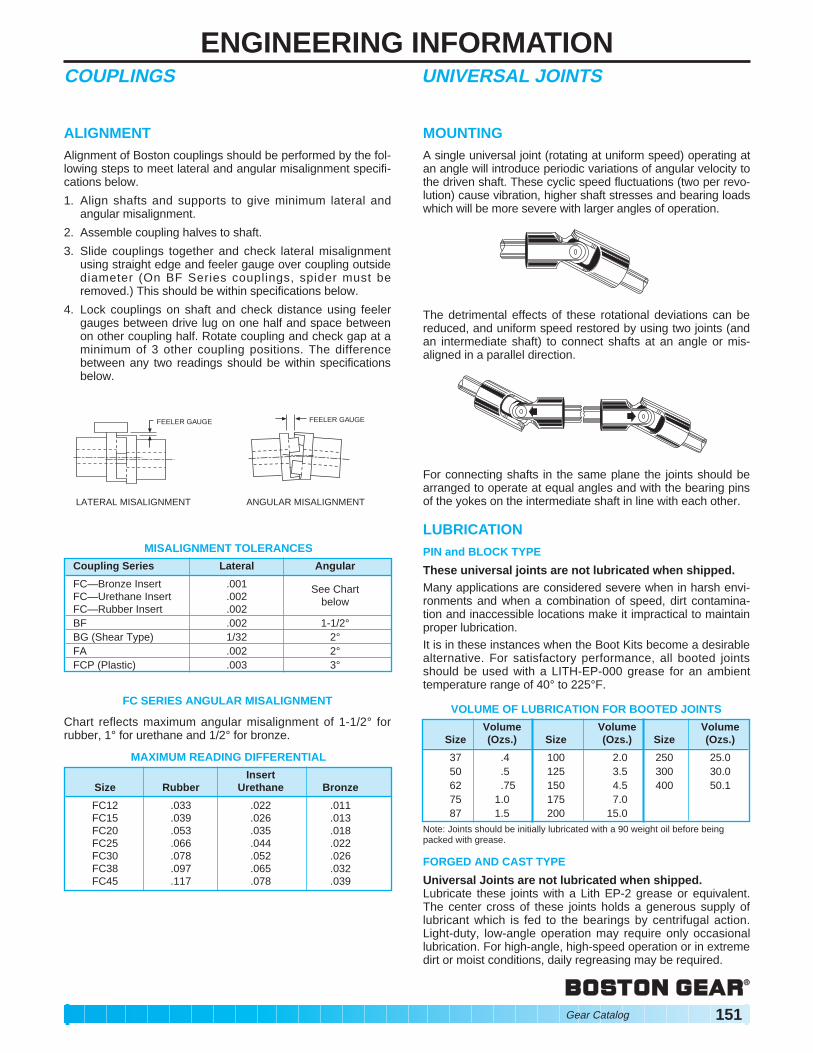
ALIGNMENT Alignment of Boston couplings should be performed by the following steps to meet lateral and angular misalignment specifications below.
1. Align shafts and supports to give minimum lateral and angular misalignment.
2. Assemble coupling halves to shaft.
3. Slide couplings together and check lateral misalignment using straight edge and feeler gauge over coupling outside diameter (On BF Series couplings, spider must be removed.) This should be within specifications below.
4. Lock couplings on shaft and check distance using feeler gauges between drive lug on one half and space between on other coupling half. Rotate coupling and check gap at a minimum of 3 other coupling positions. The difference between any two readings should be within specifications below.
FEELER GAUGE FEELER GAUGE
LATERAL MISALIGNMENT ANGULAR MISALIGNMENT
MISALIGNMENT TOLERANCES
FC SERIES ANGULAR MISALIGNMENT
Chart reflects maximum angular misalignment of 1-1/2° for rubber, 1° for urethane and 1/2° for bronze.
MOUNTING A single universal joint (rotating at uniform speed) operating at an angle will introduce periodic variations of angular velocity to the driven shaft. These cyclic speed fluctuations (two per revolution) cause vibration, higher shaft stresses and bearing loads which will be more severe with larger angles of operation.
The detrimental effects of these rotational deviations can be reduced, and uniform speed restored by using two joints (and an intermediate shaft) to connect shafts at an angle or misaligned in a parallel direction.
For connecting shafts in the same plane the joints should be arranged to operate at equal angles and with the bearing pins of the yokes on the intermediate shaft in line with each other.
LUBRICATION PIN and BLOCK TYPE
These universal joints are not lubricated when shipped. Many applications are considered severe when in harsh environments and when a combination of speed, dirt contamination and inaccessible locations make it impractical to maintain proper lubrication. It is in these instances when the Boot Kits become a desirable alternative. For satisfactory performance, all booted joints should be used with a LITH-EP-000 grease for an ambient temperature range of 40° to 225°F.
Note: Joints should be initially lubricated with a 90 weight oil before being packed with grease.
FORGED AND CAST TYPE
Universal Joints are not lubricated when shipped. Lubricate these joints with a Lith EP-2 grease or equivalent. The center cross of these joints holds a generous supply of lubricant which is fed to the bearings by centrifugal action. Light-duty, low-angle operation may require only occasional lubrication. For high-angle, high-speed operation or in extreme dirt or moist conditions, daily regreasing may be required.
MOUNTING SPUR & HELICAL For proper functioning gears, gears must be accurately aligned and supported by a shaft and bearing system which maintains alignment under load. Deflection should not exceed .001 inch at the tooth mesh for general applications. The tolerance on Center Distance normally should be positive to avoid possibility of gear teeth binding. Tolerance value is dependent on acceptable system backlash. As a guide for average application, this tolerance might vary from .002 for Boston Gear’s fine pitch gears to .005 for the coarsest pitch.
WORMS AND WORM GEAR It is important that the mounting assures the central plane of the Worm gear passes essentially through the axis of the Worm. This can be accomplished by adjusting the Worm Gear axially. Boston Worm Gears are cut to close tolerancing of the Center Line of the Gear tooth to the flush side of the Gear. When properly mounted Worm Gears will become more efficient after initial break-in period.
HOW WORM GEARS “ADJUST” THEMSELVES The gear in a worm gear reducer is made of a soft bronze material. Therefore, it can cold-work and wear-in to accommodate slight errors in misalignment.
Evolution of Contact in a Worm Gear
rotation
Leaving Entering side
Worm Initially, contact is concentrated on the leaving side of the worm.
side
After several hours or running under load, gear has cold-worked to spread area of contact.
After many hours of operation, contact has spread to cover the entire working area of the tooth.
ALTERATIONS Boston Gear Service Centers are equipped to alter catalog sprockets (rebore, keyway, setscrew, etc.). For customers, choosing to make their own alterations, the guidelines listed below should be beneficial. Alterations to hardened gears should not be made without consultation with factory. In setting up for reboring the most important consideration is to preserve the accuracy of concentricity and lateral runout provided in the original product. There are several methods for accomplishing this. One procedure is: mount the part on an arbor, machine hub diameter to provide a true running surface, remove from arbor and chuck on the hub diameter, check face and bore runout prior to reboring. As a basic rule of thumb, the maximum bore should not exceed 60% of the Hub Diameter and depending on Key size should be checked for minimum wall thickness. A minimum of one setscrew diameter over a keyway is considered adequate. Boston Gear offers a service for hardening stock sprockets. This added treatment can provide increased horsepower capacity with resultant longer life and/or reduction in size and weight. Customers wishing to do the hardening operation should refer to “Materials” below for information.
LUBRICATION The use of a straight mineral oil is recommended for most worm gear applications. This type of oil is applicable to gears of all materials, including non-metallic materials. Mild E.P. (Extreme Pressure) lubricants may be used with Iron and Steel Gears. E.P. lubricants normally should be selected of the same viscosity as straight mineral oil, E.P. lubricants are not recommended for use with brass or bronze gears. SAE80 or 90 gear oil should be satisfactory for splash lubricated gears. Where extremely high or low speed conditions are encountered, consult a lubricant manufacturer. Oil temperature of 150°F should not be exceeded for continuous duty applications. Temperatures up to 200°F can be safely tolerated for short periods of time. Many specialty lubricants have been recently developed to meet the application demands of today’s markets, including synthetics and both high and low temperature oils and greases. In those instances where Bath or Drip Feed is not practical, a moly-Disulphide grease may be used successfully, for low speed applications.
152 Gear Catalog
ENGINEERING INFORMATIONGENERAL
MATERIALS Boston Gear stock steel gears are made from a .20 carbon steel with no subsequent treatment. For those applications requiring increased wearability. Case-hardening produces a wear resistant, durable surface and a higher strength core. Carburizing and hardening is the most common process used. Several proprietary nitriding processes are available for producing an essentially distortion-free part with a relatively shallow but wear-resistant case. Boston stock worms are made of either a .20 or .45 carbon steel. Selection of material is based on size and whether furnished as hardened or untreated.
Stock cast iron gears are manufactured from ASTM-CLASS 30 cast iron to Boston Gear specifications. This provides a fine-grained material with good wear-resistant properties.
Bronze worm and helical gears are produced from several alloys selected for bearing and strength properties. Phosphor bronze is used for helicals and some worm gears (12P and coarser). Finer pitch worm gears are made from several different grades of bronze, dependent on size.
Non-metallic spur Gears listed in this Catalog are made from cotton reinforced phenolic normally referred to as Grade “C.”
Plastic Gears listed are molded from either Delrin®, Acetal or Minlon®.
STANDARD KEYWAYS AND SETSCREWS
Standard Recommended Diameter of Hole W d Setscrew
5/16 to 7/16” 3/32” 3/64” 10-32 1/2 to 9/16 1/8 1/16 1/4-20 5/8 to 7/8 3/16 3/32 5/16-18
15/16 to 1-1/4 1/4 1/8 3/8-16 1-5/16 to 1-3/8 5/16 5/32 7/16-14 1-7/16 to 1-3/4 3/8 3/16 1/2-13 1-13/16 to 2-1/4 1/2 1/4 9/16-12 2-5/16 to 2-3/4 5/8 5/16 5/8-11 2-13/16 to 3-1/4 3/4 3/8 3/4-10 3-5/16 to 3-3/4 7/8 7/16 7/8-9 3-13/16 to 4-1/2 1 1/2 1-8 4-9/16 to 5-1/2 1-1/4 7/16 1-1/8-7 5-9/16 to 6-1/2 1-1/2 1/2 1-1/4-6
DIA. OF HOLE OR D
W
d
X'
X
FORMULA:
X = (D/2)2– (W/2) 2 + d + D/2
X’ = 2X – D
EXAMPLE: Hole 1”; Keyway 1/4” wide by 1/8” deep.
X = (1/2)2 – (1/8)2 + 1/8 + 1/2 = 1.109”1.109”
X’ = 2.218 – 1.000 = 1.218”
STYLES Boston Spur, Helical, and Worm Gears are carried in Plain, Web, or Spoke styles, as illustrated.
PLAIN – A
WEB – B
WEB WITH LIGHTNING HOLES – C
SPOKE – D
Gear Catalog 153
ENGINEERING INFORMATIONHOW TO FIGURE HORSEPOWER AND TORQUE
Cut on Dotted Lines and Keep for Quick Reference
TO OBTAIN HAVING FORMULA
Velocity (V) Pitch Diameter (D) of
Feet Per Minute Gear or Sprocket – Inches V = .2618 x D x RPM & Rev. Per Min. (RPM)
Velocity (V) Ft. Per Min. VRev. Per Min. (RPM) & Pitch Diameter (D) of RPM = —————
Gear or Sprocket—Inches .2618 x D
Pitch Diameter (D) Velocity (V) Ft. Per Vof Gear or Sprocket Min. & Rev. Per Min. D = ——————
— Inches (RPM) .2618 x RPM
Torque (T) In. Lbs. Force (W) Lbs. & Radius (R) Inches
T = W x R
Force (W) Lbs. & W x VHorsepower (HP) Velocity (V) Ft. Per Min. HP = ———— 33000
Torque (T) In. Lbs. & T x RPMHorsepower (HP) Rev. Per Min. (RPM) HP = ————63025
Horsepower (HP) 63025 x HPTorque (T) In. Lbs. & Rev. Per Min. (RPM) T = ————— RPM
Horsepower (HP) & 33000 x HPForce (W) Lbs. Velocity (V) Ft. Per Min. W = ————— V
Horsepower (HP) & 63025 x HPRev. Per Min. (RPM) Torque (T) In. Lbs. RPM = —————T
33,000 x 1 HP = ————— = 1 HP
33,000 x 1 1000 x 33
HP = ———— = 1 HP33,000 x 1
FORCE (W) 1000 LBS.
DISTANCE = 33 FT.TIME = 1 MIN.
1000 LBS.
FORCE (W) = 33,000 LBS.
DISTANCE = 1 FT. TIME = 1 MIN.
33,000 LBS.
ILLUSTRATION OF HORSEPOWER
POWER is the rate of doing work.
1 hp = 36 lb-in. @ 1750 rpm 1 hp = 3 lb-ft. @ 1750 rpm
Torque (lb.-in.) x rpmhp = ————————— 63,025
Force (lb) x Velocity (ft/min.)hp = ———————————— 33,000
Velocity (ft/min.) = 0.262 x Dia. (in.) x rpm Torque (lb.-in) = Force (lb) x Radius (in.)
hp x 63,025Torque (lb.-in.) = ——————rpm
Mechanical = ———— x 100%Efficiency
OT (lb-in.) x Output rpmOutput hp = —————————— 63,025
OT = Input Torque x Ratio x Efficiency OT = Output Torque
Input rpmOutput rpm = ———— Ratio
2 TKOHL = ———— D
OHL = Overhung Load (lb) T = Shaft Torque (lb-in.) D = PD of Sprocket, Pinion or Pulley (in.) K = Overhung Load Factor
kW = hp x 0.7457 in. = mm/25.4 Temp. °C = (°F - 32) x 0.556 Temp. °F = (°C x 1.8) + 32 Torque (lb-in.) = 86.6 x kg•m Torque (lb-in.) = 8.85 x N•m Torque (lb-in.) = 88.5 x daN•m
APPLICATION FORMULAS
Output hpInput hp
WORK is the exerting of a FORCE through a DISTANCE. ONE FOOT POUND is a unit of WORK. It is the WORK done in exerting a FORCE OF ONE POUND through a DISTANCE of ONE FOOT. TORQUE (T) is the product of a FORCE (W) in pounds,
times a RADIUS (R) in inches from the center of shaft (Lever Arm) and is expressed in Inch Pounds.
T=WR=300 x 1=300 In. Lbs. T=WR=150 x 2=300 In. Lbs.
If the shaft is revolved, the FORCE (W) is moved through a distance, and WORK is done.
2LRWORK (Ft. Pounds) = W x —— x No. of Rev. of Shaft.
12
When this WORK is done in a specified TIME, POWER is used. 2LR
POWER (Ft. Pounds per Min.) = W x —— x RPM12
Since (1) HORSEPOWER = 33,000 Foot Pounds per Minute 2LR RPM WxRxRPM
HORSEPOWER (HP) = W x —— x ——— = ——————12 33,000 63,025
but TORQUE (Inch Pounds) = FORCE (W) X RADIUS (R) TORQUE (T) x RPM
Therefore HORSEPOWER (HP) = —————————63,025
R = 2"
W150*
R = 1"
W300*
THE AMOUNT OF WORK done (Foot Pounds) is the FORCE (Pounds) exerted multiplied by the DISTANCE (Feet) through which the FORCE acts. THE AMOUNT OF POWER used (Foot Pounds per Minute) is the WORK (Foot Pounds) done divided by the TIME (Minutes) required.
WORK (Ft. Lbs.)POWER (Foot Pounds per Minute) = ————————
TIME (Minutes)
POWER is usually expressed in terms of HORSEPOWER.
HORSEPOWER is POWER (Foot Pounds per Minute) divided by 33000.
POWER (Ft. Lbs. per Minute)HORSEPOWER (HP) = ————————————