81

ENGINEERING DRAWING
Graphical means of expression of
technical details without the
barrier of a language.
Universal language for Engineers
What will you learn from this course?
How to communicate technical information.
• Visualization – the ability to mentally understand visual
information.
• Graphics theory – geometry and projection techniques used for preparation of drawings.
• Standards – set of rules for preparation of technical drawings. Conventions – commonly accepted practices in technical drawings.
• Tools – devices used to create technical drawings and models.
• Applications – the various uses for technical drawings.

Graphic language: mode of communication through SKETCHES
Drawing: graphical representation of an OBJECT
Engineering Drawing
Drawing of an object contains all the necessary information,
required for the construction/fabrication of the object, like
➢ actual shape, ➢ accurate sizes, ➢ manufacturing methods, ➢ materials to be used etc.,

List of tools required for the drawing practice session
10
Sl. No. Item Quantity
1 Mini-drafter (or T-Square) 1
2 Engineering Drawing Box 1
3 French curves 1 set
4 Set-square 1 set
5 Protractor 1
6 Drawing Clip 1 set
7 Lead pencil/clutch pencil 2-3
8 Lead (HB, H & 2H) 1 each set
9 Eraser 1
10 Sand paper/cello tape 1
11 Blade / pencil sharpener 1
12 Drawing Sheet 1 per session
➢ Students without Engineering Drawing Box will not be allowed to
attend the practical session.
➢ School Instrument box is not allowed.

Mini-drafter
1 1
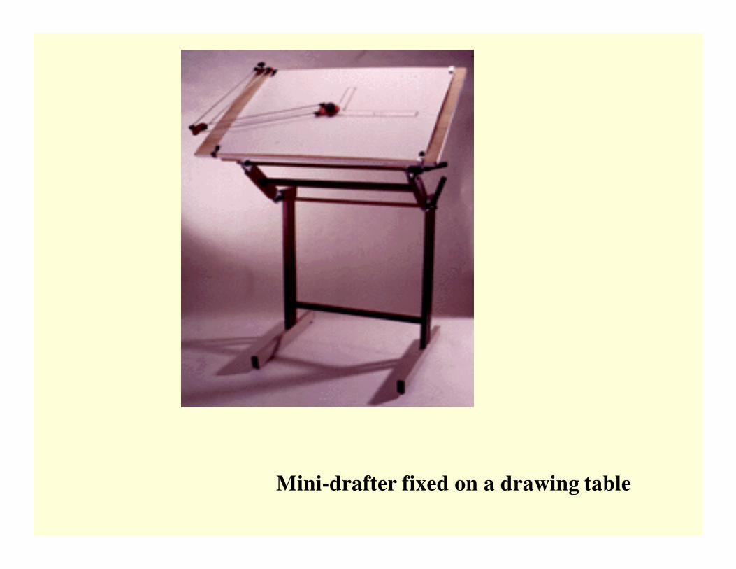
Mini-drafter fixed on a drawing table

Set-square
French Curves
Drawing Clips

Scale set

Engineering Drawing Box


Pencils
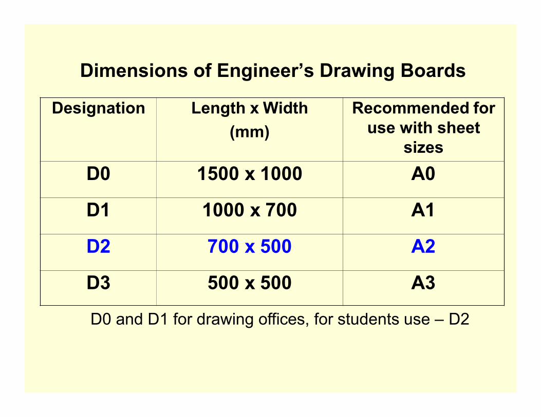
Dimensions of Engineer’s Drawing Boards
Designation Length x Width
(mm)
Recommended for
use with sheet
sizes
D0 1500 x 1000 A0
D1 1000 x 700 A1
D2 700 x 500 A2
D3 500 x 500 A3
D0 and D1 for drawing offices, for students use – D2

Standard sizes of drawing sheets as per BIS
Designation Size
(mm)
A0 841 x 1189
A1 594 x 841
A2 420 x 594
A3 297 x 420
A4 210 x 297

Drawing
Sheet
Sizes

Drawing sheet Layout

Title Block

LINES AND LETTERING*
LINES
Lines are the basic feature of a drawing. A line may
be straight, curved, continuous, segmented, thin,
thick, etc., each having its own specific sense.
Line strokes refer to the directions of drawing
straight and curved lines
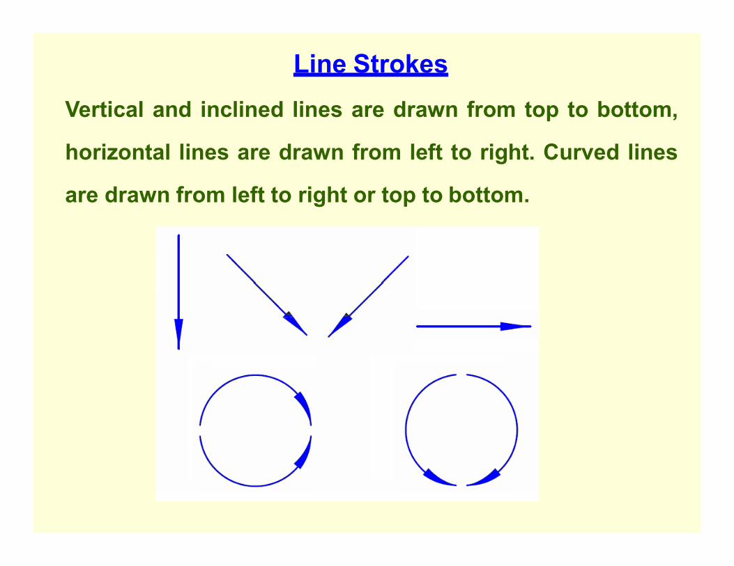
Line Strokes
Vertical and inclined lines are drawn from top to bottom,
horizontal lines are drawn from left to right. Curved lines
are drawn from left to right or top to bottom.

Line types
Illustration Application
Thick Outlines, visible edges, surface
boundaries of objects, margin lines
Continuous thin Dimension lines, extension lines,
section lines leader or pointer lines,
construction lines, boarder lines
Continuous thin wavy Short break lines or irregular
boundary lines – drawn freehand
Continuous thin with zig-zag Long break lines
Short dashes, gap 1, length 3 mm Invisible or interior surfaces

Line types
Illustration Application
Short dashes Center lines, locus lines
Alternate long and short
dashes in a proportion of 6:1,
Long chain thick at end and
thin elsewhere
Cutting plane lines
Continuous thick border line Border

Uses of different types of lines in a given drawing
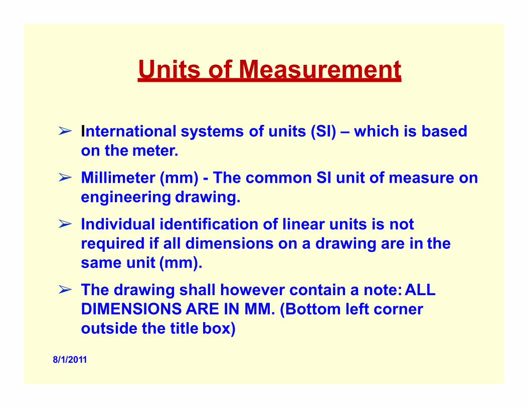
Units of Measurement
➢ International systems of units (SI) – which is based
on the meter.
➢ Millimeter (mm) - The common SI unit of measure on
engineering drawing.
➢ Individual identification of linear units is not
required if all dimensions on a drawing are in the
same unit (mm).
➢ The drawing shall however contain a note: ALL
DIMENSIONS ARE IN MM. (Bottom left corner
outside the title box)
8/1/2011

Dimensioning
➢ Indicating on a drawing, the size of the object and
other details essential for its construction and
function, using lines, numerals, symbols, notes, etc.
➢ Dimensions indicated on a drawing should be those
that are essential for the production, inspection and
functioning of the object.
➢ Dimensions indicated should not be mistaken as
those that are required to make the drawing of an
object.

An example
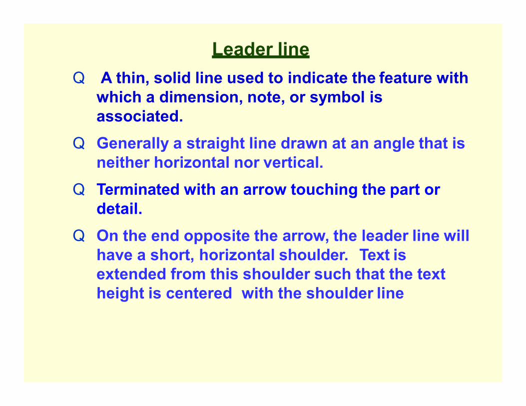
Leader line
Q A thin, solid line used to indicate the feature with
which a dimension, note, or symbol is
associated.
Q Generally a straight line drawn at an angle that is
neither horizontal nor vertical.
Q Terminated with an arrow touching the part or
detail.
Q On the end opposite the arrow, the leader line will
have a short, horizontal shoulder. Text is
extended from this shoulder such that the text
height is centered with the shoulder line

Arrows
3 mm wide and should be 1/3rd as wide as they are
long - symbols placed at the end of dimension lines to
show the limits of the dimension. Arrows are uniform
in size and style, regardless of the size of the drawing.
33

Spacing of Dimensions

Placing of Dimensions
Orientation of Dimensioning Text

Dimensioning of angles
36
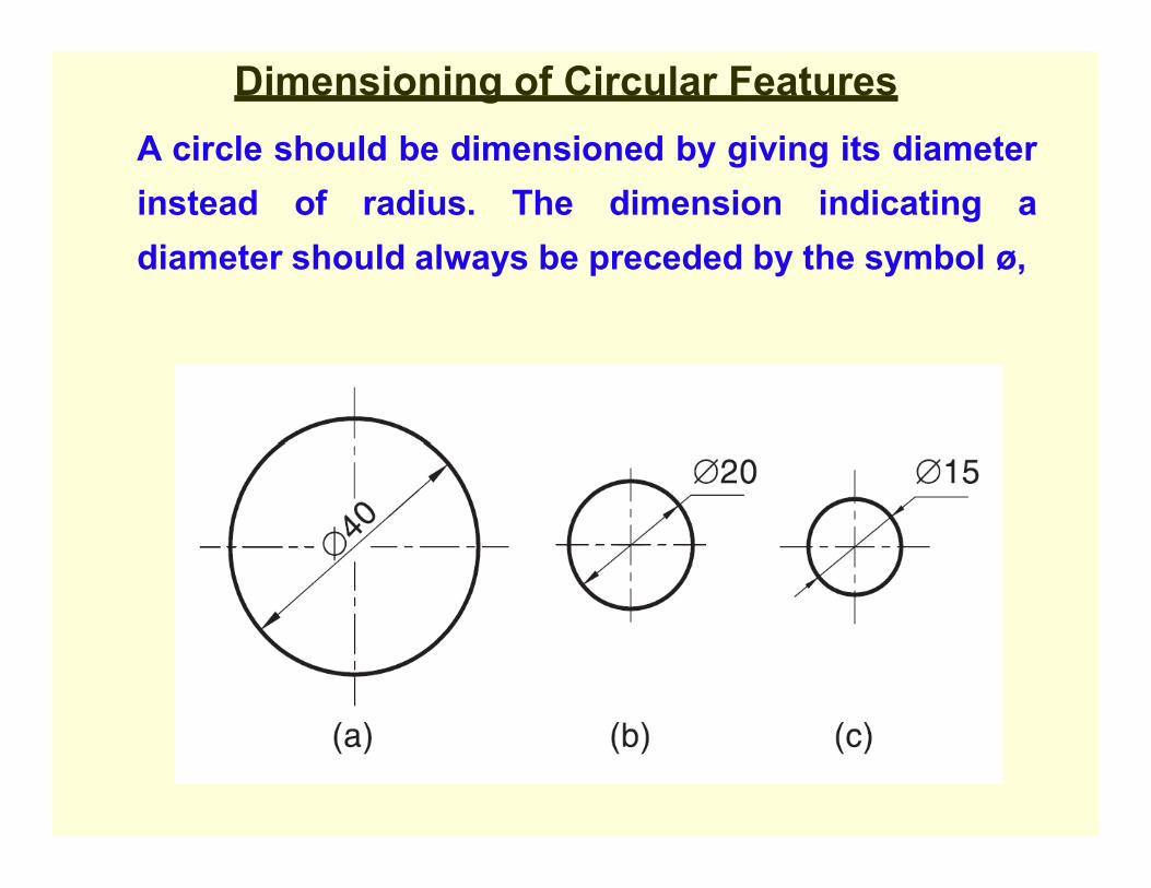
Dimensioning of Circular Features
A circle should be dimensioned by giving its diameter
instead of radius. The dimension indicating a
diameter should always be preceded by the symbol ø,

Dimensioning a Length
Depends on Available Space

Dimensioning Radii
Arcs of Circle Precede with ‘R’ to distinguish from length

RULES OF DIMENSIONING
1. Between any two extension lines, there must be one and only one
dimension line bearing one dimension.
2. As far as possible, all the dimensions should be placed outside the
views. Inside dimensions are preferred only if they are clearer and
more easily readable.
3. All the dimensions on a drawing must be shown using either Aligned
System or Unidirectional System. In no case should, the two systems
be mixed on the same drawing.
4. The same unit of length should be used for all the dimensions on a
drawing. The unit should not be written after each dimension, but a
note mentioning the unit should be placed below the drawing.
5. Dimension lines should not cross each other. Dimension lines should
also not cross any other lines of the object.
6. All dimensions must be given.
7. Each dimension should be given only once. No dimension should be
redundant.
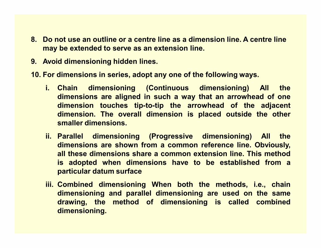
8. Do not use an outline or a centre line as a dimension line. A centre line
may be extended to serve as an extension line.
9. Avoid dimensioning hidden lines.
10. For dimensions in series, adopt any one of the following ways.
i. Chain dimensioning (Continuous dimensioning) All the
dimensions are aligned in such a way that an arrowhead of one
dimension touches tip-to-tip the arrowhead of the adjacent
dimension. The overall dimension is placed outside the other
smaller dimensions.
ii. Parallel dimensioning (Progressive dimensioning) All the
dimensions are shown from a common reference line. Obviously,
all these dimensions share a common extension line. This method
is adopted when dimensions have to be established from a
particular datum surface
iii. Combined dimensioning When both the methods, i.e., chain
dimensioning and parallel dimensioning are used on the same
drawing, the method of dimensioning is called combined
dimensioning.

Dimensioning Guidelines
Avoid crossing extension lines
Multiple extension
line crossings may
be confused for
the outside corner
of the part.

•Single stroke refers to the thickness obtained in one stroke of a pencil
or ink pen .
•It does not mean that the pencil or pen should not be lifted while
completing a particular letter.
Lettering types
• Lettering A – Height of the capital letter is divided into 14 equal parts
• Lettering B – Height of the capital letter is divided into 10 equal parts

Specifications of A -Type Lettering
Specifications
Value
Size (mm)
Capital letter height h 2.5 3.5 5 7 10 14 20
Lowercase letter height a = (5/7)h - 2.5 3.5 5 7 10 14
Thickness of lines b = (1/14)h 0.18 0.25 0.35 0.5 0.7 1 1.4
Spacing between
characters
c = (1/7)h 0.35 0.5 0.7 1 1.4 2 2.8
Min. spacing b/n words d = (3/7)h 1.05 1.5 2.1 3 4.2 6 8.4
Min. spacing b/n baselines e = (10/7)h 3.5 5 7 10 14 20 28
Ratio of height to width varies, but in most cases is 6:5 Ratio of height to width varies, but in most cases is 6:5

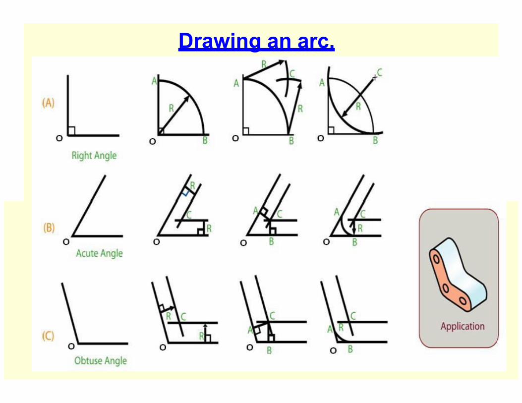
Geometric Construction
• Construction of primitive geometric
forms (points, lines and planes etc.)
that serve as the building blocks for
more complicated geometric shapes.
• Defining the position of the object in
space

Lines and
Planes

Solids

Curved
surfaces

Primitive
geometric
forms • Point
• Line
• Plane
• Solid
• ……etc

The basic 2-D geometric primitives, from which
other more complex geometric forms are
derived.
➢ Points,
➢ Lines,
➢ Circles, and
➢ Arcs.

Point
that has neither ➢ A theoretical location
width, height, nor depth.
➢
➢ A point is represented in technical drawing
as a small cross made of dashes that are
approximately 3 mm long.

Relationship of one line to another line or arc

Bisecting
a line

Dividing a line
into equal parts
Steps:
• Draw a line MO at any convenient angle (preferably an acute
angle) from point M.
• From M and along MO, cut off with a divider equal divisions
(say three) of any convenient length.
• Draw a line joining RN.
• Draw lines parallel to RN through the remaining points on line
MO. The intersection of these lines with line MN will divide the
line into (three) equal parts.

Planar tangent condition exists when two
geometric forms meet at a single point and do
not intersect.

Locating tangent points
on circle and arcs

Drawing an arc tangent to a given point on the line
Steps
• Given line
tangent
Construct
AB and
point T.
a line
perpendicular to line AB
and through point T.
• Locate the center of the
arc by making the radius
on the perpendicular
line. Put the point of the
compass at the center of
the arc, set the compass
for the radius of the arc,
and draw the arc which
will be tangent to the line
through the point T.
Drawing an arc,
tangent to two lines

Drawing an arc, tangent to a line and an arc
(a) that do not intersect (b) that intersect

General method of
drawing any polygon Draw AB = given length of polygon
At B, Draw BP perpendicular & = AB
Draw Straight line AP
With center B and radius AB, draw arc AP.
The perpendicular bisector of AB meets st. line AP and arc AP in 4 and 6 respectively.
Draw circles with centers as 4, 5,&6 and radii as 4B, 5B, & 6B and inscribe a square, pentagon, & hexagon in the respective circles.
Mark point 7, 8, etc with 6-7,7-8,etc. = 4-5 to get the centers of circles of heptagon and octagon, etc.

To draw a circle touching
three lines inclined to
each other but not
forming a triangle.
● Let AB, BC, and AD be the lines.
● Draw bisectors of the two angles, intersecting at O.
● From O draw a perpendicular to any one line intersecting it at P.
● With O as center and OP as radius draw the desired circle.
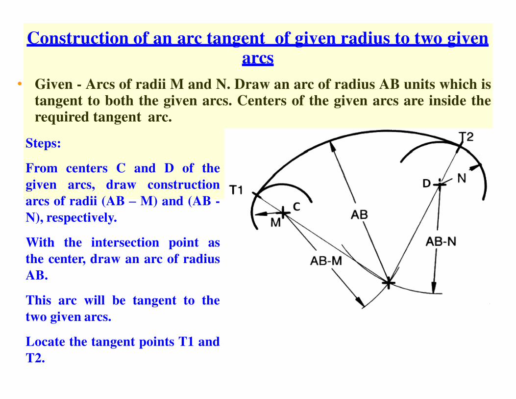
Construction of an arc tangent of given radius to two given arcs
• Given - Arcs of radii M and N. Draw an arc of radius AB units which is tangent to both the given arcs. Centers of the given arcs are inside the required tangent arc.
Steps:
From centers C and D of the
given arcs, draw construction
arcs of radii (AB – M) and (AB -
N), respectively.
With the intersection point as
the center, draw an arc of radius
AB.
This arc will be tangent to the
two given arcs.
Locate the tangent points T1 and
T2.

Construction of line tangents
to two circles (Open belt) Given: Circles of radii R1 and R with centers O and P, respectively.
Steps:
With P as center and a radius equal to (R-R1) draw an arc.
Locate the midpoint of OP as perpendicular bisector of OP as “M”. With M as centre and Mo as radius draw a semicircle.
Locate the intersection between the semicircle
point T
and the circle with radius (R-R1).
draw a line PT and extend it to locate T1.
Draw OT2 parallel to PT1.
The line T1 to T2 is the required tangent

Construction of line tangents to two circles (crossed belt)
Given: Two circles of radii R1 and R with centers O and P, respectively.
Steps:
Using P as a center and a radius equal to (R+ R1) draw an arc.
Through O draw a tangent to this arc.
Draw a line PT cutting the circle at T1
Through O draw a line OT2
parallel to PT1.
The line T1T2 is the required tangent.
ENGINEERING CURVES

When eccentricity
< 1 Ellipse
=1 Parabola
> 1 Hyperbola
Eccentrici ty Distance of the point from the focus
Distance of the point from the directric
2
eg. when e=1/2, the curve is an Ellipse, when e=1, it is a parabola
and when e=2, it is a hyperbola.

Focus-Directrix or
Eccentricity Method Given : the distance of focus from the directrix and eccentricity
Example : Draw an ellipse if the distance of focus from the directrix is 70 mm and the eccentricity is 3/4.
1.Draw the directrix AB and axis CC’
2.Mark F on CC’ such that CF = 70 mm.
3. Divide CF into 7 equal
mark V at the parts and 3
fourth division from C.
Now, e = FV/ CV = 3/4.
4. At V, erect a
perpendicular VB = VF.
Join CB. Through F, draw a
line at 45° to meet CB
produced at D. Through D,
drop a perpendicular DV’ on CC’. Mark O at the
midpoint of V– V’.

Focus-Directrix or Eccentricity Method ( Continued)
5. With F as a centre and radius = 1–1’, cut two arcs on the
perpendicular through 1 to locate P1 and P1’. Similarly, with F as
centre and radii = 2– 2’, 3–3’, etc., cut arcs on the corresponding
perpendiculars to locate P2 and P2’, P3 and P3’, etc. Also, cut
similar arcs on the perpendicular through O to locate V1 and V1’.
6. Draw a smooth closed curve passing through V, P1, P/2, P/3,
…, V1, …, V’, …, V1’, … P/3’, P/2’, P1’.
7. Mark F’ on CC’ such that V’ F’ = VF.
4

Constructing a Parabola (Eccentricity Method)
5
Example. Draw a parabola if the distance of the focus from
the directrix is 60 mm.
1.Draw directrix AB and axis CC’ as shown.
2.Mark F on CC’ such that CF = 60 mm.
3.Mark V at the midpoint of CF. Therefore, e = VF/ VC = 1.
4.At V, erect a perpendicular VB = VF. Join CB.
5.Mark a few points, say, 1, 2, 3, … on VC’ and erect perpendiculars through them
meeting CB produced at 1’, 2’, 3’, …
6.With F as a centre and radius = 1–1’, cut two arcs on the perpendicular through 1 to
locate P1 and P1’. Similarly, with F as a centre and radii = 2–2’, 3–3’, etc., cut arcs
on the corresponding perpendiculars to locate P2 and P2’, P3 and P3’, etc.
7.Draw a smooth curve passing through V, P1, P2, P3 … P3’, P2’, P1’.

Constructing a Hyperbola (Eccentricity Method)
Draw a hyperbola
of e = 3/2 if the
distance of the focus
from the directrix =
50 mm.
Construction similar
to ellipse and
parabola
6

Drawing Tangent and
Normal to any conic
7
When a tangent at any point on the curve (P) is produced to meet
the directrix, the line joining the focus with this meeting point (FT) will be
at right angle to the line joining the focus with the point of contact (PF).
The normal to the curve at any point is perpendicular to the tangent
at that point.

Another definition of the ellipse
An ellipse is the set of all points in a plane for which the sum of
the distances from the two fixed points (the foci) in the plane is
constant.
8

Arcs of Circle
Method Given conditions: (1) the major axis and minor axis are known OR
(2) the major axis and the distance between the foci are known
Draw AB & CD perpendicular to each other as the major diameter minor
diameter respectively.
With centre as C or D, and half the major diameter as radius draw arcs to intersect the
major diameter to obtain the foci at X and Y.
Mark a number of points along line segment XY and number them. Points need not
be equidistant.
Set the compass to radius B-1 and draw two arcs, with Y as center. Set the compass to
radius A1, and draw two arcs with X as center. Intersection points of the two arcs are
points on the ellipse. Repeat this step for all the remaining points.
Use the French curve to connect the points, thus drawing the ellipse.
9

Constructing an Ellipse (Concentric Circle Method)
Given:
Major axis
and minor
axis
• With center C, draw two concentric circles with diameters equal to major and minor
diameters of the ellipse. Draw the major and minor diameters.
• Construct a line AB at any angle through C. Mark points D and E where the
line intersects the smaller circle.
• From points A and B, draw lines parallel to the minor diameter. Draw lines parallel to
the major diameter through D & E.
• The intersection of the lines from A and D is point F, and from B and E is point G.
Points F & G lies on the ellipse.
• Extend lines FD & BG and lines AF and GE to obtain two more points in the other
quadrants.
• Repeat steps 2-6 to create more points in each quadrant and then draw a
smo10oth curve through the points.

Constructing a Parabola
(Parallelogram Method) Example: Draw a parabola of base 100 mm and axis 50 mm if the
axis makes 70° to the base.
11
1. Draw the base RS = 100 mm and through its midpoint K, draw the axis KV = 50 mm, inclined
at 70° to RS. Draw a parallelogram RSMN such that SM is parallel and equal to KV.
2. Divide RN and RK into the same number of equal parts, say 5. Number the divisions as 1, 2, 3, 4
and 1’, 2’, 3’, 4’, starting from R.
3. Join V–1, V–2, V–3 and V–4. Through 1’, 2’, 3’ and 4’, draw lines parallel to KV to meet V–1 at
P1, V–2 at P2, V–3 at P3 and V–4 at P4, respectively.
4. Obtain P5, P6, P7 and P8 in the other half of the rectangle in a similar way. Alternatively, these
points can be obtained by drawing lines parallel to RS through P1, P2, P3 and P4. For example,
draw P1– P8 such that P1– x = x– P8. Join P1, P2, P3 … P8 to obtain the parabola.

Hyperbola
A Hyperbola is obtained
plane, when a section
parallel/inclined to the
axis cuts the cone on one
side of the axis.
A Rectangular Hyperbola is
obtained when a
section, parallel to the axis
cuts the cone on one side of
the axis.
12

Hyperbola Mathematical definition
A hyperbola is defined as
the set of
points
whose
from
in a plane
distances
two fixed
13
points called foci, in
the plane have a
constant difference.
Constructing a
Hyperbola Draw
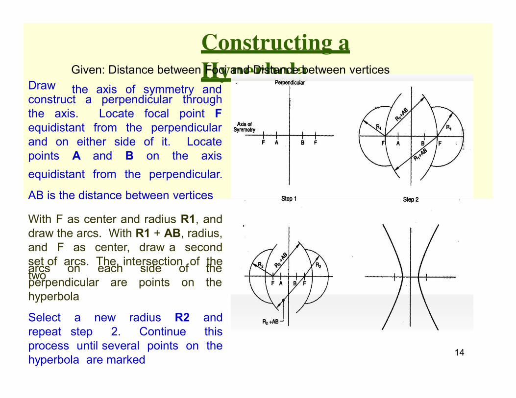
Given: Distance between Foci and Distance between vertices
the axis of symmetry and construct a perpendicular through
the axis. Locate focal point F
equidistant from the perpendicular
and on either side of it. Locate
B on the axis points A and
equidistant from the perpendicular.
AB is the distance between vertices
With F as center and radius R1, and
draw the arcs. With R1 + AB, radius,
and F as center, draw a second
set of arcs. The intersection of the
two
14
arcs on each
perpendicular are
hyperbola
side
points
of the
on the
Select a new radius R2 and
repeat step 2. Continue this
process until several points on the
hyperbola are marked
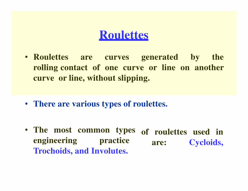
Roulettes
• Roulettes are curves generated by the
rolling contact of one curve or line on another
curve or line, without slipping.
• There are various types of roulettes.
• The most common types
engineering practice
Trochoids, and Involutes.
of roulettes
are:
used in
Cycloids,

Cycloid
Generating circle
Base line
A Cycloid is generated by a point on the circumference of a
circle rolling along a straight line without slipping
The rolling circle is called the Generating circle
The straight line is called the Directing line or Base line

Constructing a
cycloid
➢ Generating circle has its center at C and has a radius of C-P’. Straight line PP’ is
equal in length to the circumference of the circle and is tangent to the
circle at point P’. ➢ Divide the circle into a number of equal segments, such as 12. Number
the intersections of the radii and the circle.
➢ From each point of intersection on the circle, draw a construction line parallel to line
PP’ and extending up to line P’C’. ➢ Divide the line CC’ into the same number of equal parts, and number them. Draw
vertical lines from each point to intersect the extended horizontal centerline of the
circle. Label each point as C1, C2, C3, …. C12.
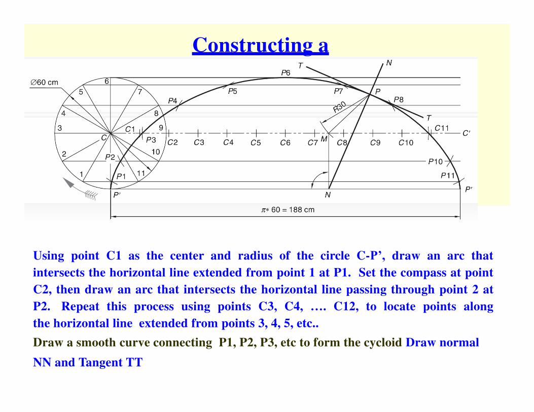
Constructing a
cycloid (contd.)
Using point C1 as the center and radius of the circle C-P’, draw an arc that
intersects the horizontal line extended from point 1 at P1. Set the compass at point
C2, then draw an arc that intersects the horizontal line passing through point 2 at
P2. Repeat this process using points C3, C4, …. C12, to locate points along
the horizontal line extended from points 3, 4, 5, etc..
Draw a smooth curve connecting P1, P2, P3, etc to form the cycloid Draw normal
NN and Tangent TT

Epicycloid
The cycloid is called Epicycloid when the generating circle
rolls along another circle outside it.

Constructing an
Epicycloid
1) With O as centre and OC as radius, draw an arc to represent locus of
centre.
2) Divide arc PQ in to 12 equal parts and name them as 1’, 2’, …., 12’.
3) Join O1’, O2’, … and produce them to cut the locus of centres at C1, C2, …. 4) Taking C1 as centre, and radius equal to 20 mm, draw an arc cutting the arc
through 1 at P1. Similarly obtain points P2, P3,…., P12. 5) Join P1, P2….. With French curve

Hypocycloid
Hypocycloid is obtained when the generating circle rolls
along another circle inside it.

Constructing an
Hypocycloid
Construction is similar to epicycloid. The generating
circle is to be drawn below the base circle

Classification of Cycloidal curves
Generating Circle
On the
directing line
Outside the
directing line
Inside the
directing line
Generating
point
On the
generating
circle
Cycloid Epicycloid Hypocycloid
Outside the
generating
circle
Superior
trochoid
Superior
epitrochoid
Superior
Hypotrochoid
Inside the
generating
circle
Inferior
trochoid
Inferior
epitrochoid
Inferior
hypotrochoid


