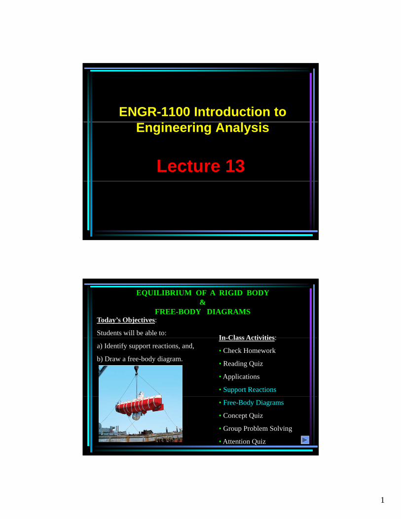
1 ENGR-1100 Introduction to Lecture 13 Engineering Analysis EQUILIBRIUM OF A RIGID BODY & FREE-BODY DIAGRAMS In Class Activities: Today’s Objectives : Students will be able to: In-Class Activities : • Check Homework • Reading Quiz • Applications • Support Reactions a) Identify support reactions, and, b) Draw a free-body diagram. • Free-Body Diagrams • Concept Quiz • Group Problem Solving • Attention Quiz
Transcript
1
ENGR-1100 Introduction to
Lecture 13
Engineering Analysis
EQUILIBRIUM OF A RIGID BODY &
FREE-BODY DIAGRAMS
In Class Activities:
Today’s Objectives:
Students will be able to:In-Class Activities:
• Check Homework
• Reading Quiz
• Applications
• Support Reactions
a) Identify support reactions, and,
b) Draw a free-body diagram.
• Free-Body Diagrams
• Concept Quiz
• Group Problem Solving
• Attention Quiz
2
EQUATIONS OF EQUILIBRIUM & TWO- AND THREE-FORCE MEMEBERS
In-Class Activities:
Today’s Objectives:
Students will be able to:In Class Activities:
• Reading Quiz
• Applications
• Equations of Equilibrium
a) Apply equations of equilibrium tosolve for unknowns, and,
b) Recognize two-force members.
• Two-Force Members
•Concept Quiz
•Group Problem Solving
•Attention Quiz
APPLICATIONS
The truck ramps have a weight of 400 lb each. Each ramp is pinned to the body of the truck and held in the position by a cable. How can we determine the cable tension
How are the idealized model and the free body diagram used to do this?
Which diagram above is the idealized model?
and support reactions?
3
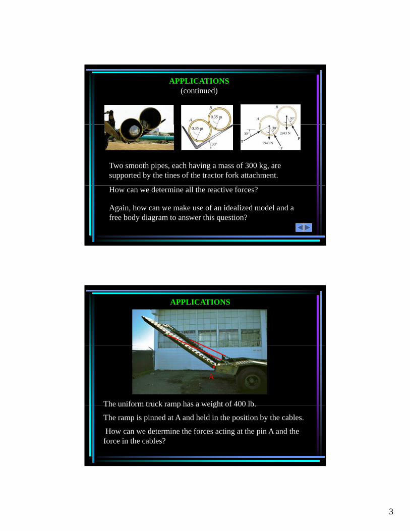
APPLICATIONS (continued)
Two smooth pipes, each having a mass of 300 kg, are supported by the tines of the tractor fork attachment.
Again, how can we make use of an idealized model and a free body diagram to answer this question?
How can we determine all the reactive forces?
APPLICATIONS
The uniform truck ramp has a weight of 400 lb.
A
The uniform truck ramp has a weight of 400 lb.
The ramp is pinned at A and held in the position by the cables.
How can we determine the forces acting at the pin A and the force in the cables?
4
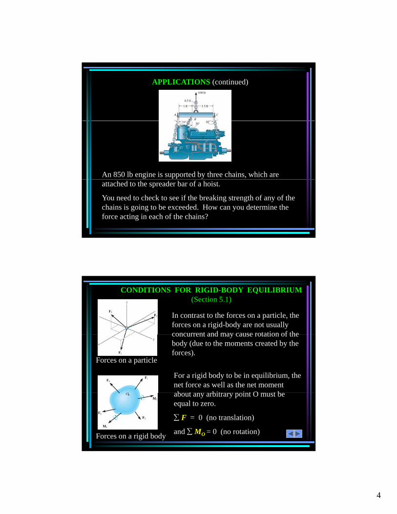
APPLICATIONS (continued)
An 850 lb engine is supported by three chains, which are attached to the spreader bar of a hoist.
You need to check to see if the breaking strength of any of the chains is going to be exceeded. How can you determine the force acting in each of the chains?
CONDITIONS FOR RIGID-BODY EQUILIBRIUM (Section 5.1)
In contrast to the forces on a particle, the forces on a rigid-body are not usually concurrent and may cause rotation of theconcurrent and may cause rotation of the body (due to the moments created by the forces).
Forces on a particle
For a rigid body to be in equilibrium, the net force as well as the net moment b t bit i t O t babout any arbitrary point O must be
equal to zero.
F = 0 (no translation)
and MO = 0 (no rotation)Forces on a rigid body
5
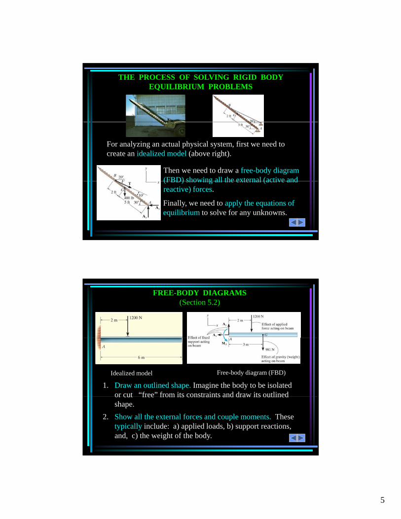
THE PROCESS OF SOLVING RIGID BODY EQUILIBRIUM PROBLEMS
For analyzing an actual physical system, first we need to create an idealized model (above right).
Then we need to draw a free-body diagram (FBD) showing all the external (active and
Finally, we need to apply the equations of equilibrium to solve for any unknowns.
(FBD) showing all the external (active and reactive) forces.
FREE-BODY DIAGRAMS (Section 5.2)
Idealized model Free-body diagram (FBD)
1. Draw an outlined shape. Imagine the body to be isolated or cut “free” from its constraints and draw its outlined
2. Show all the external forces and couple moments. These typically include: a) applied loads, b) support reactions, and, c) the weight of the body.
or cut free from its constraints and draw its outlined shape.
6
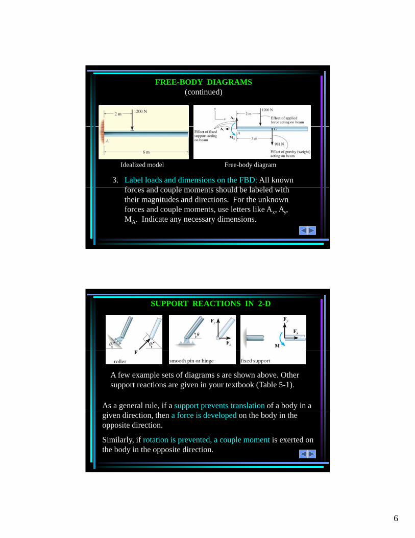
FREE-BODY DIAGRAMS (continued)
3. Label loads and dimensions on the FBD: All known f d l t h ld b l b l d ith
Idealized model Free-body diagram
forces and couple moments should be labeled with their magnitudes and directions. For the unknown forces and couple moments, use letters like Ax, Ay, MA. Indicate any necessary dimensions.
SUPPORT REACTIONS IN 2-D
As a general rule, if a support prevents translation of a body in a
A few example sets of diagrams s are shown above. Other support reactions are given in your textbook (Table 5-1).
given direction, then a force is developed on the body in the opposite direction.
Similarly, if rotation is prevented, a couple moment is exerted on the body in the opposite direction.
7
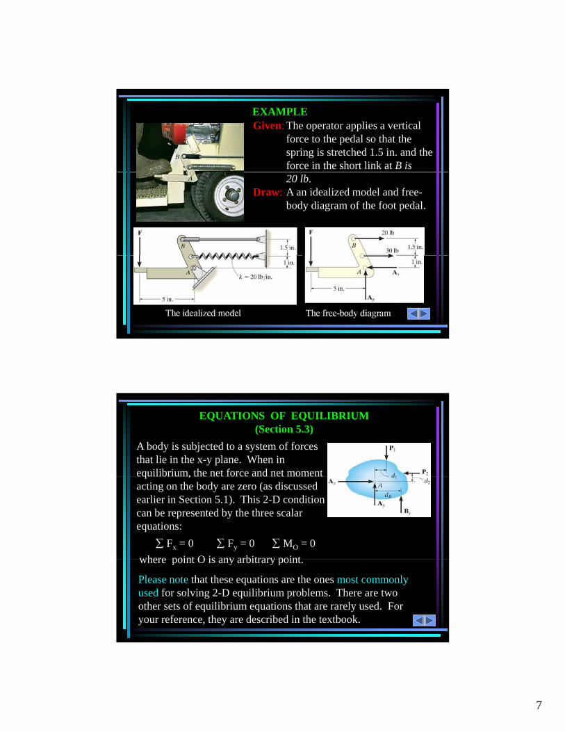
EXAMPLEGiven: The operator applies a vertical
force to the pedal so that the spring is stretched 1.5 in. and the force in the short link at B is 20 lb.
Draw: A an idealized model and free-body diagram of the foot pedal.
EQUATIONS OF EQUILIBRIUM (Section 5.3)
A body is subjected to a system of forces that lie in the x-y plane. When in equilibrium, the net force and net moment
Fx = 0 Fy = 0 MO = 0
where point O is any arbitrary point
equilibrium, the net force and net moment acting on the body are zero (as discussed earlier in Section 5.1). This 2-D condition can be represented by the three scalar equations:
where point O is any arbitrary point.
Please note that these equations are the ones most commonly used for solving 2-D equilibrium problems. There are two other sets of equilibrium equations that are rarely used. For your reference, they are described in the textbook.
8
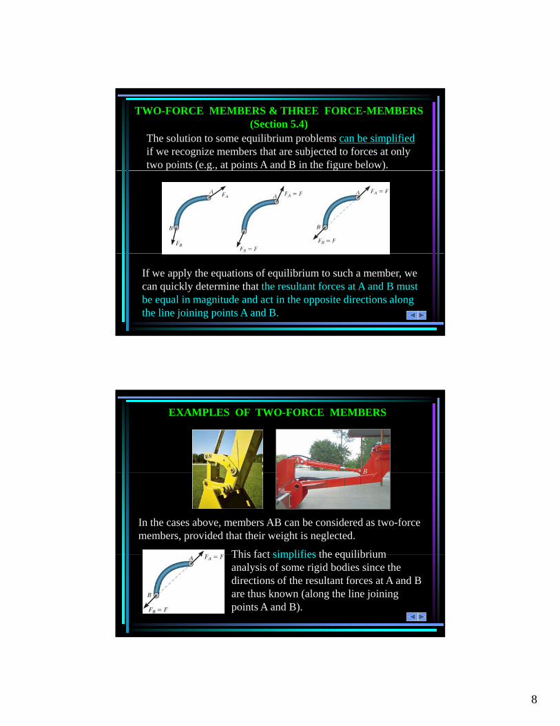
TWO-FORCE MEMBERS & THREE FORCE-MEMBERS (Section 5.4)
The solution to some equilibrium problems can be simplifiedif we recognize members that are subjected to forces at only two points (e.g., at points A and B in the figure below).
If we apply the equations of equilibrium to such a member, we can quickly determine that the resultant forces at A and B must be equal in magnitude and act in the opposite directions along the line joining points A and B.
EXAMPLES OF TWO-FORCE MEMBERS
This fact simplifies the equilibrium
In the cases above, members AB can be considered as two-force members, provided that their weight is neglected.
This fact simplifies the equilibrium analysis of some rigid bodies since the directions of the resultant forces at A and B are thus known (along the line joining points A and B).
9
STEPS FOR SOLVING 2-D EQUILIBRIUM PROBLEMS
1. If not given, establish a suitable x - y coordinate system.
2. Draw a free-body diagram (FBD) of the object under analysis.
3. Apply the three equations of equilibrium (E-of-E) to solve for the unknowns.
IMPORTANT NOTES
1. If there are more unknowns than the number of independent equations, then we have a statically indeterminate situation.We cannot solve these problems using just statics.We cannot solve these problems using just statics.
2. The order in which we apply equations may affect the simplicity of the solution. For example, if we have two unknown vertical forces and one unknown horizontal force,then solving FX = 0 first allows us to find the horizontal unknown quickly.q y
3. If the answer for an unknown comes out as negative number, then the sense (direction) of the unknown force is opposite to that assumed when starting the problem.
10
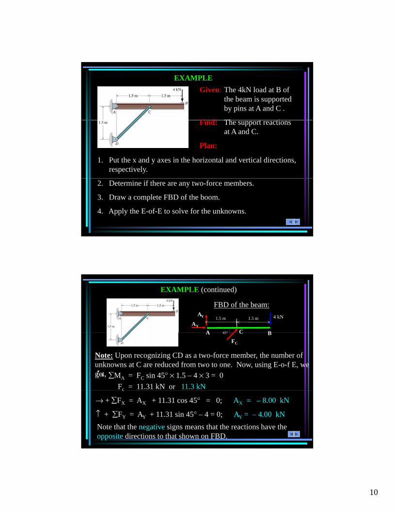
EXAMPLE
Given: The 4kN load at B of the beam is supported by pins at A and C .
Fi d Th t ti
1. Put the x and y axes in the horizontal and vertical directions, respectively.
Find: The support reactions at A and C.
Plan:
2. Determine if there are any two-force members.
3. Draw a complete FBD of the boom.
4. Apply the E-of-E to solve for the unknowns.
EXAMPLE (continued)
FBD of the beam:
AX
AY
A
1.5 m
C B
4 kN
45°
1.5 m
Note: Upon recognizing CD as a two-force member, the number of unknowns at C are reduced from two to one. Now, using E-o-f E, we get,+ MA = FC sin 45° × 1.5 – 4 × 3 = 0
Fc = 11.31 kN or 11.3 kN
A C BFC
45°
→ + FX = AX + 11.31 cos 45° = 0; AX = – 8.00 kN
↑ + FY = AY + 11.31 sin 45° – 4 = 0; AY = – 4.00 kN
c
Note that the negative signs means that the reactions have the opposite directions to that shown on FBD.
11
READING QUIZ
1. If a support prevents translation of a body, then the support exerts a ___________ on the body.
A) Couple moment
B) ForceB) Force
C) Both A and B.
D) None of the above
2. Internal forces are _________ shown on the free body diagram of a whole body.
A) Always
B) Often
C) Rarely
D) Never
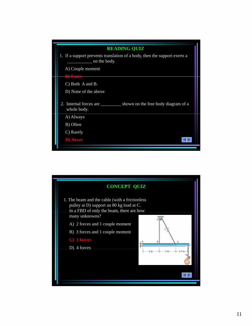
CONCEPT QUIZ
1. The beam and the cable (with a frictionless pulley at D) support an 80 kg load at C. In a FBD of only the beam, there are how y ,many unknowns?
A) 2 forces and 1 couple moment
B) 3 forces and 1 couple moment
C) 3 forces
D) 4 forces)
12
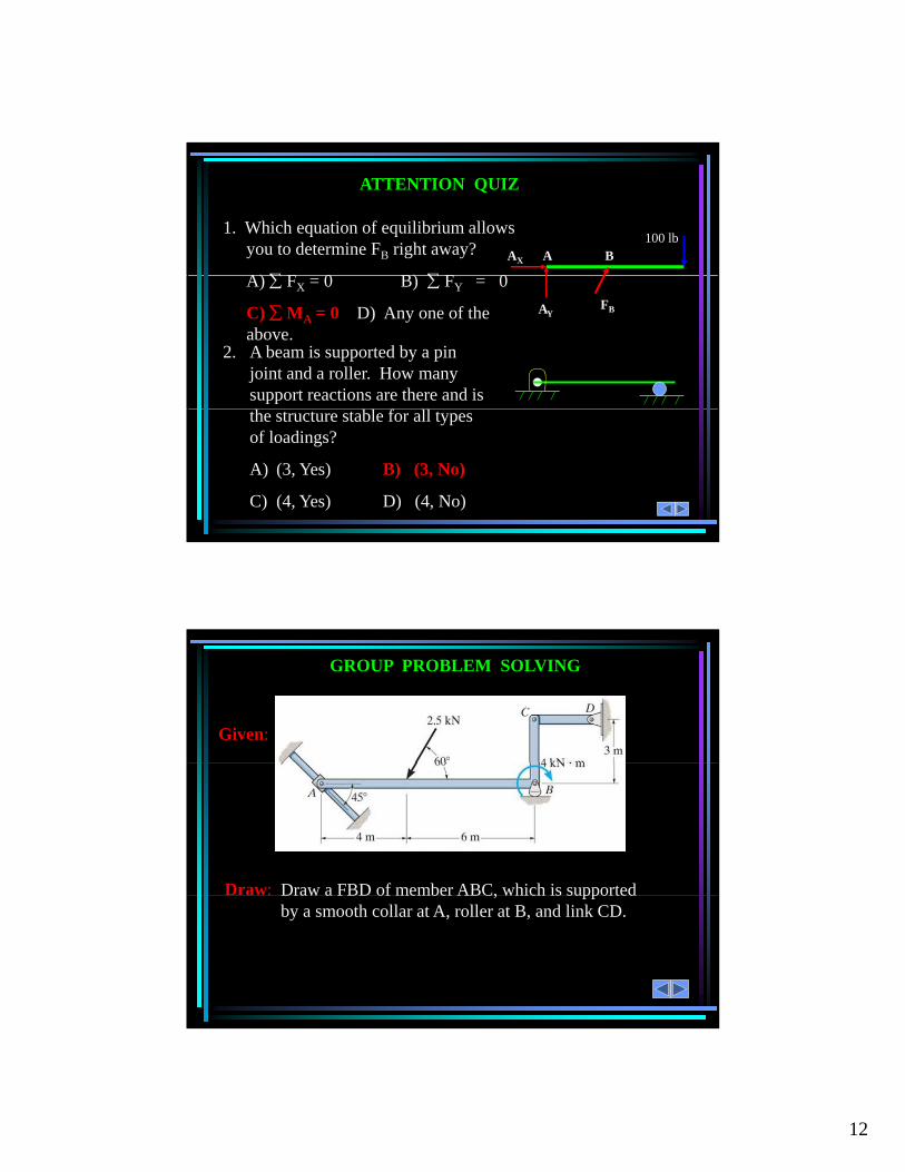
ATTENTION QUIZ
1. Which equation of equilibrium allows you to determine FB right away?
A) F 0 B) F 0
AX A B100 lb
A) FX = 0 B) FY = 0
C) MA = 0 D) Any one of the above.
2. A beam is supported by a pin joint and a roller. How many support reactions are there and is
FBAY
the structure stable for all types of loadings?
A) (3, Yes) B) (3, No)
C) (4, Yes) D) (4, No)
GROUP PROBLEM SOLVING
Given:
Draw a FBD of member ABC, which is supported Draw: C, ppby a smooth collar at A, roller at B, and link CD.
13
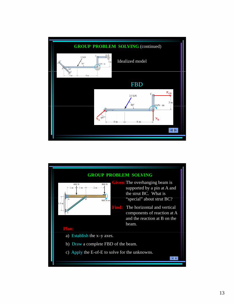
GROUP PROBLEM SOLVING (continued)
Idealized model
FBD
GROUP PROBLEM SOLVING
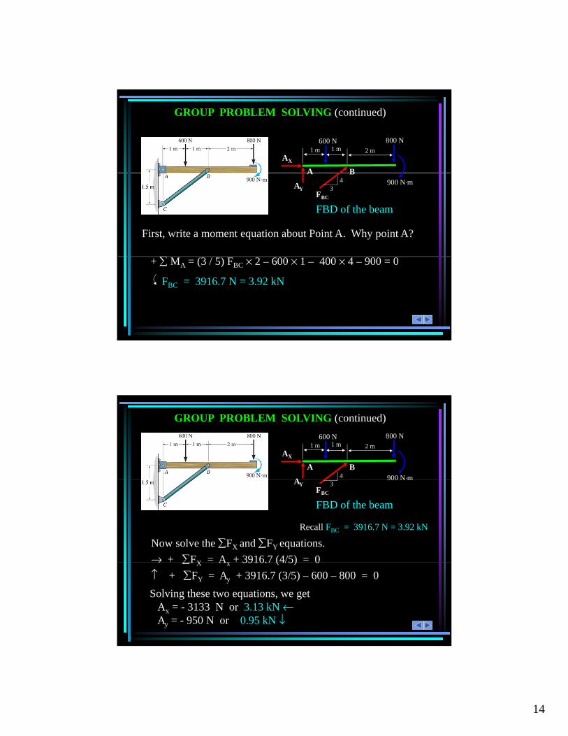
Given:The overhanging beam is supported by a pin at A and the strut BC. What is “ i l” b t t t BC?“special” about strut BC?
Find: The horizontal and vertical components of reaction at A and the reaction at B on the beam.
Plan:
a) Establish the x–y axes.
b) Draw a complete FBD of the beam.
c) Apply the E-of-E to solve for the unknowns.
14
GROUP PROBLEM SOLVING (continued)
1 m 2 m
600 N 800 N
BA
AX
1 m
First, write a moment equation about Point A. Why point A?