Enhanced magnetodielectric effect and optical property of lead-freemultiferroic (1 � x)(Bi0.5Na0.5)TiO3/xCoFe2O4 composites
Jyoti Rani a, K.L. Yadav a, *, Satya Prakash b
a Smart Materials Research Laboratory, Department of Physics, Indian Institute of Technology Roorkee, Roorkee 247667, Indiab Metallurgical and Materials Engineering Department, Indian Institute of Technology Roorkee, Roorkee 247667, India
h i g h l i g h t s
� (1 � x)BNT/xCFO composites synthesized by solid state reaction methods.� Distinct ferroelectric and ferrite phases were observed in XRD and FESEM analysis.� Magnetization was increased with increasing CFO concentration.� Magnetocapacitance was enhanced with increasing CFO content in composites.� Red shift in optical band gap of BNT was observed with CFO addition.
a r t i c l e i n f o
Article history:Received 3 January 2014Received in revised form3 July 2014Accepted 7 July 2014Available online 23 July 2014
(1 � x)(Bi0.5Na0.5)TiO3/xCoFe2O4 composites with x ¼ 0, 0.1, 0.2, 0.3, 0.4 and 0.5 were synthesized by solidstate reaction method. Presence of distinct ferroelectric (Bi0.5Na0.5)TiO3 and ferrite CoFe2O4 phases in theprepared composites have been confirmed by the X-ray diffraction analysis and field emission scanningelectron micrographs. The variation of dielectric constant with temperature for these prepared com-posites show an anomaly near antiferroelectric to paraelectric phase transition temperature (~345 �C) ofpure (Bi0.5Na0.5)TiO3 ceramics. The dielectric constant of the composites at low frequency range de-creases with increase in CoFe2O4 content up to x ¼ 0.3 but increases for x ¼ 0.4 and x ¼ 0.5. The value ofremnant magnetization for 10 and 50% CoFe2O4 are 2 and 14 emu g�1 respectively. The maximum valueof magnetocapacitance was found to be ~4.37% for 50% CoFe2O4 content. Increase in CoFe2O4 content incomposites shifts the optical band gap of (Bi0.5Na0.5)TiO3 towards lower energy side.
Multiferroic materials exhibit both ferroelectric and magneticproperties simultaneously. These materials may also show thecoupling between ferroelectricity and magnetism. This couplingbehaviour is known as magnetoelectric (ME) effect [1]. These MEmaterials are of great interest due to their applications in spin-tronics, transducers, sensors and four-state logic memories [2].
TheMEmaterials are of two types: single phase and composites.Few single phase ME materials exist due to the incompatibilitybetween the mode of generation of ferroelectricity and magnetism.Ferroelectricity requires an off center shift of B-site cation which is
favoured by empty d orbital of B-site cation while magnetism re-quires localized transition d-electrons in B-site cation [1]. The MEeffect in the single phase materials is much smaller and so it limitstheir application in devices [3]. The fabrication of composite ma-terials having both ferroelectric and ferrite phases provide a po-tential way to manufacture new ME materials with desirableproperties [4,5]. Ferroelectriceferrite composites are the physicalmixture of ferroelectric and ferrite phases having different chemi-cal compositions but are insoluble in each other [6]. The ME effectin a composite is a product property which arises from the couplingbetween piezoelectric and magnetostrictive effect in the ferro-electric andmagnetic phase, respectively. In order to achieve strongmagnetoelectric coupling in composites, it is desirable to have aferroelectric phase with large piezoelectric response and magneticphase with large magnetostriction coefficient, respectively. Theapplication of the magnetic field on these composites generates themechanical stresses in the ferrite phase due to magnetostriction.
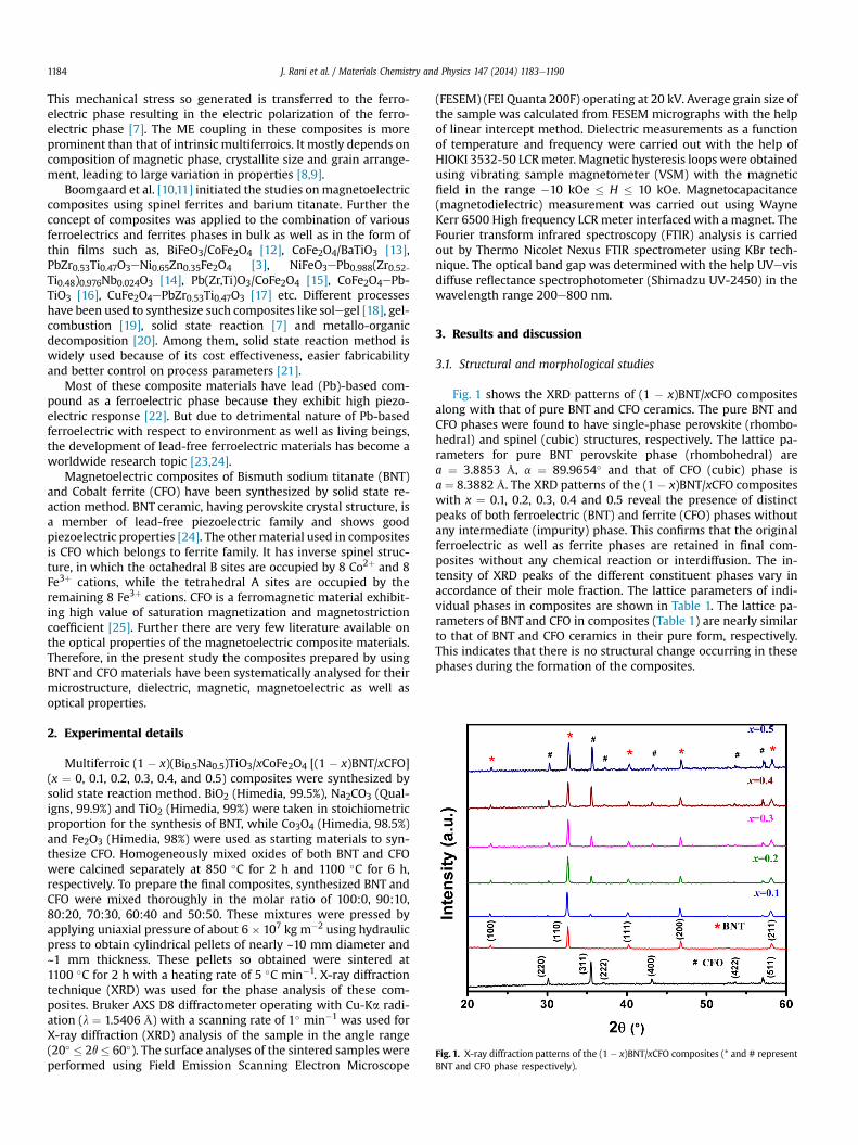
Fig. 1. X-ray diffraction patterns of the (1 � x)BNT/xCFO composites (* and # representBNT and CFO phase respectively).
J. Rani et al. / Materials Chemistry and Physics 147 (2014) 1183e11901184
This mechanical stress so generated is transferred to the ferro-electric phase resulting in the electric polarization of the ferro-electric phase [7]. The ME coupling in these composites is moreprominent than that of intrinsic multiferroics. It mostly depends oncomposition of magnetic phase, crystallite size and grain arrange-ment, leading to large variation in properties [8,9].
Boomgaard et al. [10,11] initiated the studies onmagnetoelectriccomposites using spinel ferrites and barium titanate. Further theconcept of composites was applied to the combination of variousferroelectrics and ferrites phases in bulk as well as in the form ofthin films such as, BiFeO3/CoFe2O4 [12], CoFe2O4/BaTiO3 [13],PbZr0.53Ti0.47O3eNi0.65Zn0.35Fe2O4 [3], NiFeO3ePb0.988(Zr0.52-Ti0.48)0.976Nb0.024O3 [14], Pb(Zr,Ti)O3/CoFe2O4 [15], CoFe2O4ePb-TiO3 [16], CuFe2O4ePbZr0.53Ti0.47O3 [17] etc. Different processeshave been used to synthesize such composites like solegel [18], gel-combustion [19], solid state reaction [7] and metallo-organicdecomposition [20]. Among them, solid state reaction method iswidely used because of its cost effectiveness, easier fabricabilityand better control on process parameters [21].
Most of these composite materials have lead (Pb)-based com-pound as a ferroelectric phase because they exhibit high piezo-electric response [22]. But due to detrimental nature of Pb-basedferroelectric with respect to environment as well as living beings,the development of lead-free ferroelectric materials has become aworldwide research topic [23,24].
Magnetoelectric composites of Bismuth sodium titanate (BNT)and Cobalt ferrite (CFO) have been synthesized by solid state re-action method. BNT ceramic, having perovskite crystal structure, isa member of lead-free piezoelectric family and shows goodpiezoelectric properties [24]. The other material used in compositesis CFO which belongs to ferrite family. It has inverse spinel struc-ture, in which the octahedral B sites are occupied by 8 Co2þ and 8Fe3þ cations, while the tetrahedral A sites are occupied by theremaining 8 Fe3þ cations. CFO is a ferromagnetic material exhibit-ing high value of saturation magnetization and magnetostrictioncoefficient [25]. Further there are very few literature available onthe optical properties of the magnetoelectric composite materials.Therefore, in the present study the composites prepared by usingBNT and CFO materials have been systematically analysed for theirmicrostructure, dielectric, magnetic, magnetoelectric as well asoptical properties.
2. Experimental details
Multiferroic (1 � x)(Bi0.5Na0.5)TiO3/xCoFe2O4 [(1 � x)BNT/xCFO](x ¼ 0, 0.1, 0.2, 0.3, 0.4, and 0.5) composites were synthesized bysolid state reaction method. BiO2 (Himedia, 99.5%), Na2CO3 (Qual-igns, 99.9%) and TiO2 (Himedia, 99%) were taken in stoichiometricproportion for the synthesis of BNT, while Co3O4 (Himedia, 98.5%)and Fe2O3 (Himedia, 98%) were used as starting materials to syn-thesize CFO. Homogeneously mixed oxides of both BNT and CFOwere calcined separately at 850 �C for 2 h and 1100 �C for 6 h,respectively. To prepare the final composites, synthesized BNT andCFO were mixed thoroughly in the molar ratio of 100:0, 90:10,80:20, 70:30, 60:40 and 50:50. These mixtures were pressed byapplying uniaxial pressure of about 6 � 107 kg m�2 using hydraulicpress to obtain cylindrical pellets of nearly ~10 mm diameter and~1 mm thickness. These pellets so obtained were sintered at1100 �C for 2 h with a heating rate of 5 �C min�1. X-ray diffractiontechnique (XRD) was used for the phase analysis of these com-posites. Bruker AXS D8 diffractometer operating with Cu-Ka radi-ation (l ¼ 1.5406 Å) with a scanning rate of 1� min�1 was used forX-ray diffraction (XRD) analysis of the sample in the angle range(20� � 2q � 60�). The surface analyses of the sintered samples wereperformed using Field Emission Scanning Electron Microscope
(FESEM) (FEI Quanta 200F) operating at 20 kV. Average grain size ofthe sample was calculated from FESEM micrographs with the helpof linear intercept method. Dielectric measurements as a functionof temperature and frequency were carried out with the help ofHIOKI 3532-50 LCRmeter. Magnetic hysteresis loops were obtainedusing vibrating sample magnetometer (VSM) with the magneticfield in the range �10 kOe � H � 10 kOe. Magnetocapacitance(magnetodielectric) measurement was carried out using WayneKerr 6500 High frequency LCR meter interfaced with a magnet. TheFourier transform infrared spectroscopy (FTIR) analysis is carriedout by Thermo Nicolet Nexus FTIR spectrometer using KBr tech-nique. The optical band gap was determined with the help UVevisdiffuse reflectance spectrophotometer (Shimadzu UV-2450) in thewavelength range 200e800 nm.
3. Results and discussion
3.1. Structural and morphological studies
Fig. 1 shows the XRD patterns of (1 � x)BNT/xCFO compositesalong with that of pure BNT and CFO ceramics. The pure BNT andCFO phases were found to have single-phase perovskite (rhombo-hedral) and spinel (cubic) structures, respectively. The lattice pa-rameters for pure BNT perovskite phase (rhombohedral) area ¼ 3.8853 Å, a ¼ 89.9654� and that of CFO (cubic) phase isa ¼ 8.3882 Å. The XRD patterns of the (1 � x)BNT/xCFO compositeswith x ¼ 0.1, 0.2, 0.3, 0.4 and 0.5 reveal the presence of distinctpeaks of both ferroelectric (BNT) and ferrite (CFO) phases withoutany intermediate (impurity) phase. This confirms that the originalferroelectric as well as ferrite phases are retained in final com-posites without any chemical reaction or interdiffusion. The in-tensity of XRD peaks of the different constituent phases vary inaccordance of their mole fraction. The lattice parameters of indi-vidual phases in composites are shown in Table 1. The lattice pa-rameters of BNT and CFO in composites (Table 1) are nearly similarto that of BNT and CFO ceramics in their pure form, respectively.This indicates that there is no structural change occurring in thesephases during the formation of the composites.
Table 1Lattice parameters of individual phase, magnetocapacitance and band gap energy(Eg) for (1 � x)BNT/xCFO composites.
Compositions(1 � x)BNT/xCFO
Lattice parameters Magnetocapacitance(%)
Eg (eV)
Ferroelectricphase
Ferritephase
a (Å) a (�) a (Å)
0 3.885 89.965 e e 3.140.1 3.898 89.928 8.375 1.09 2.970.2 3.880 89.901 8.370 1.90 2.900.3 3.876 89.836 8.375 2.27 2.880.4 3.880 89.879 8.350 2.92 2.690.5 3.866 89.875 8.353 4.37 2.44CFO e e 8.388 e e
J. Rani et al. / Materials Chemistry and Physics 147 (2014) 1183e1190 1185
Fig. 2 shows the FESEM micrographs of (1 � x)BNT/xCFO com-posites alongwith that of pure CFO and BNTceramics. It can be seenfrom micrographs that the average grain size of pure BNT is~2e3 mm and that of pure CFO is ~0.3e0.6 mm. In all synthesizedcomposites, homogeneous dispersion of small grains (CFO) in thelarge grained (BNT) matrix can be observed. Thus, the morpho-logical analysis reveals the formation of compact microstructurewith distinguishable phases in composites. The FESEMmicrographsof the composites support the presence of two distinct phases,implying the successful formation of (1 � x)BNT/xCFO composites.
3.2. Dielectric study
3.2.1. Frequency dependency of dielectric propertiesFig. 3(a) and (b) shows the variation of dielectric constant (εr)
and loss tangent (tan d) of (1 � x)BNT/xCFO (x ¼ 0, 0.1, 0.2, 0.3, 0.4and 0.5) composites as a function of frequency over a range
Fig. 2. FESEM micrographs of (a) CFO (b) BNT (c) to (g) (1 � x
0.1 kHze1MHz at room temperature. Pure BNT shows high value ofεr and low tan d which remain nearly constant with increase infrequency. The incorporation of CFO in the BNT causes the decreasein the value of εr and increases in tan d. The value of εr for thecomposites decreases up to 30% CFO content which can be attrib-uted to incorporation of CFO which is a kind of semiconductormaterial in a dielectric BNT matrix thereby diluting its dielectricproperties. But beyond 30% CFO concentration, the value of εr startsto increase at lower frequencies that may be due to major contri-bution of space charge polarization above 30% CFO content. Thedispersion of εr at low frequency region for 40% and 50% CFOcontaining composites can be explained by MaxwelleWagner [26]polarization theory. MaxwelleWagner mechanism is connectedwith uncompensated surface charge at ferroelectriceferrite inter-face of the composites. When an electric field is applied to thecomposites, the space charge provided by the ferrite phase accu-mulates at the interface of the two phases due to presence ofdifferent permittivities and conductivities. As the degree of in-homogeneity increases in the system, their activation energy de-creases drastically leading to a change in dielectric properties of thesystem [14]. In higher frequency range, εr shows nearly constantbehaviour which may be due to the inability of some polarizationsto follow applied alternating electric field. In composites, electronhopping between Fe2þ 4 Fe3þ results in orientational polarizationin ferrite phase. At higher frequency the hopping of electron be-tween Fe2þ 4 Fe3þ ion does not follow the applied electric fieldand hence does not contribute to dielectric constant [7].
3.2.2. Temperature dependency of dielectric propertiesFig. 4(a)e(f) illustrates the dielectric constant (εr) of composites
(1 � x)BNT/xCFO as a function of temperature at 1, 10, 100 kHz and
)BNT3/x CFO composites for x ¼ 0.1, 0.2, 0.3, 0.4 and 0.5.
Fig. 3. (a) Dielectric constant (εr) and (b) dielectric loss (tan d) of (1 � x)BNT/xCFO composites as a function of frequency at room temperature.
J. Rani et al. / Materials Chemistry and Physics 147 (2014) 1183e11901186
1 MHz frequencies. The maximum dielectric constant (εr-max) ofpure BNT is ~2580 at 1 MHz with anti-ferroelectric to paraelectricphase transition temperature ~345 �C, which is in agreement withthe reported value for BNT [27]. The εr-max of pure BNT is found tohave approximately same value at all frequencies i.e., nearly inde-pendent of frequency which indicate its non relaxor behaviour. Incomposites, the dielectric constant exhibits an anomaly which canbe ascribed to the antiferroelectric to paraelectric phase transitiontemperature of pure BNT. The dielectric anomaly in these com-posites shifted towards higher temperature with increase in fre-quency that depicts their relaxor behaviour.
Fig. 5(a) and (b) shows the variation of dielectric constant (εr)and dielectric loss (tan d) for (1� x)BNT/xCFO (x¼ 0, 0.1, 0.2, 0.3, 0.4and 0.5) composites with temperature at a frequency of 1 kHz. Thecomposites show high value of εr at high temperature which isascribed to the electronic hopping between Fe2þand Fe3þ ions andhole hopping between Co2þ and Co3þ ions in the spinel structure.Hopping mechanism results in local displacement of charge alongthe direction of applied electric field causing the polarization inferrites. At low frequency and high temperatures, the electronhopping mechanism dominates, giving a high value of εr for thecomposites [28,29]. Increase in CFO content in the composites in-creases the number of Co and Fe ions thereby leading to the in-crease in the value of εr with increasing concentration of CFO athigh temperature. The value of tan d of the composites increaseswith increase in temperature. This may be due to the increase inconductivity of composites with increase in temperature [14].
3.3. Magnetic properties
Fig. 6(a) displays the magnetization versus magnetic field (MeHhysteresis loops) plot at room temperature for (1 � x)BNT/xCFOcomposites where x ¼ 0.1, 0.2, 0.3, 0.4 and 0.5. The hysteresis loopsreveal that all composites exhibit well saturated typical ferromag-netic behaviour. The values of saturationmagnetization (Ms) as wellas remnant magnetization (Mr) were found to increase with in-crease in mole fraction of CFO in the composites. Fig. 6(b) indicatesthe variation of 2Ms, 2Mr andmagnetic moment (mB) as a function ofCFO concentration. The obtained value of remnant magnetization isfound to be higher than one previously reported in literature [30].The magnetic moment of the composites in terms of Bohrmagnetron was determined by using following relation [31]:
mB ¼ M � s0s�5585 (1)
where mB is Bohr's magnetron, M and s0s represent the molecularweight andmagnetization per grammol of the sample, respectivelyand 5585 is the magnetic factor. The increase in values of themagnetization and the magnetic moment (mB) may be a contribu-tion of the ferrite grains which act as centres of magnetization andthe saturation magnetization of the composites is the vector sum ofall these individual contributions [7]. Further, increase in CFOcontent result in increase of these ferrite grains contributions to theincreased magnetization. The value of saturation magnetization ofthe composites is less than that of pure CFO ceramic (shown in insetof Fig. 6(a)). This decrease in the value of Ms may be due to for-mation of antiphase boundaries (APBs) in composites as suggestedby Wang et al. [16] in case of CFOePTO multiferroic composites.There is a slight variation found in coercivity of composites withincrease in CFO concentration which lies in the range ~611e747 Oe.The coercivity of the prepared composites is much lower than thatof pure CFO (~1022 Oe) suggesting the easy-magnetization char-acteristic of these composites.
3.4. Magnetodielectric study
Fig. 7(a) illustrates the room temperature magnetocapacitance(or magnetodielectric) of (1 � x)BNT/xCFO composites; x ¼ 0.1, 0.2,0.3, 0.4 and 0.5 in the range of magnetic field from 0 to 8 kOe at1 kHz frequency. The magnetoelectric coupling can be evaluatedindirectly by measuring the variation in the dielectric constant as afunction of applied magnetic field. In magnetoelectric materials, anapplied magnetic field not only affect the magnetic order but alsochanges the dielectric constant [32]. The change in capacitance onthe application of external magnetic field at a constant frequency iscalled magnetocapacitance. The magnetocapacitance (MC) isdefined as
MC ¼ ½εðHÞ � εð0Þ�εð0Þ � 100% (2)
where ε(H) and ε(0) represent the value of dielectric constant in thepresence and absence of magnetic field H respectively. The value ofdielectric constant of the synthesized composites is found to in-crease with increase in magnetic field. When an external magneticfield is applied to the composites, it gets strained via magneto-striction. This magnetostriction in the ferrite phase produces stresswhich gets transferred to the ferroelectric phase, resulting in anelectric polarization of the ferroelectric phase via ME effect [33]which modifies the dielectric behaviour. The value of percentage
Fig. 4. Dielectric constant (εr) of (1 � x)BNT/xCFO composites as a function of temperature at 1, 10, 100 kHz and 1 MHz frequencies (a) x ¼ 0, (b) x ¼ 0.1, (c) x ¼ 0.2, (d) x ¼ 0.3, (e)x ¼ 0.4, (f) x ¼ 0.5.
J. Rani et al. / Materials Chemistry and Physics 147 (2014) 1183e1190 1187
magnetocapacitance at 8 kOe of all composites is given in Table 1.Highest value of magnetocapacitance is found for x ¼ 0.5, con-taining equal mole fraction of BNT and CFO which may be due tobetter mechanical coupling between the two phases in this equi-molar configuration [29]. The value of magnetocapacitance of thesecomposites is significantly higher than the previously reported forNiFe2O4eNa0.5Bi0.5TiO3 [33], BiFe0.5Cr0.5O3eNiFe2O4 [34] compos-ites. In a ferroelectromagnet, thermodynamic potential (F) can beexpressed as
F ¼ F0 þ aP2 þ b
2P4 � PE þ a0M2 þ b0
2M4 �MH þ gP2M2 (3)
Fig. 5. (a) Dielectric constant (εr), (b) dielectric loss (tan d) of (1 � x
where P and M are the order parameters for polarization andmagnetization, respectively and a, b, a0; b0 and g are coupling co-efficients. The term representing exchange magnetoelectric inter-action, is valid for all ferroelectromagnets. This free energyexpression is used by Kimura et al. [35] to evaluate the impact ofmagnetic ordering on the dielectric susceptibility and indicatedthat the difference of relative dielectric constant will be propor-tional to the square of the magnetic-order parameter i.e., DεegM2.The sign of Dε depends on the sign of the constant magnetoelectricinteraction, and can be either positive or negative [18]. The varia-tion of Dε=εð0Þ as a function of Dε=εð0Þ for 0.7BNT/0.3CFO is shownin Fig. 7(b) and its inset shows the M2 versus H plot for x ¼ 0.3. The
)BNT/xCFO composites versus temperature at 1 kHz frequency.
Fig. 6. (a) Magnetization versus magnetic field (MeH) curves. Inset shows MeH loop for pure CFO, (b) saturation magnetization (2Ms), remnant magnetization (2Mr) and magneticmoment (mB) variation with CFO content for (1 � x)BNT/xCFO composites at room temperature.
J. Rani et al. / Materials Chemistry and Physics 147 (2014) 1183e11901188
linear fitting with this formula gives the value of g ~ 6.28 � 10�5
(emu g�1)�2 for 0.7BNT/0.3CFO composite. Similarly the value of ghave been calculated for other compositions and are found to be3.87 � 10�4, 1.35 � 10�4, 4.13 � 10�5 and 4.86 � 10�4 (emu g�1)�2
for x ¼ 0.1, 0.2, 0.4 and 0.5 composites, respectively.
3.5. Optical properties
3.5.1. Fourier transform infrared spectroscopy (FTIR)FTIR spectra of (1 � x)BNT/xCFO composites along with that of
pure BNT and CFO phase are shown in Fig. 8. FTIR of compositesdepicts the presence of fundamental vibrations of metal oxygenbonds of constituent BNT and CFO phases. The band around~603 cm�1 is associated with the asymmetrical stretching vibrationof TieO of BNT phase [36,37]. The band around ~649 cm�1 may beattributed to the bending mode of vibration of bismuth oxide [38].The absorption band at ~408 cm�1 and ~597 cm�1 correspond tothe vibration of group Fe3þeO2� (MeO) at octahedral and tetra-hedral sites, respectively [19,39]. As the concentration of CFO in-creases, the band corresponding to (MtetraeO) dominates incomposites.
Fig. 7. (a) Magnetocapacitance of (1 � x)BNT/xCFO; x ¼ 0.1, 0.2, 0.3, 0.4 and 0.5 composite0.7BNT/0.3CFO composite. Inset shows variation of (magnetization)2 with magnetic field (H
3.5.2. Optical band gap calculationThe optical band gap of the (1 � x)BNT/xCFO composites have
been determined with the help of diffuse reflectance spectra. Thereflectance data have been translated in terms of absorbance by theapplication of the KubelkaeMunk function. The KubelkaeMunktheory is generally used for the analysis of diffuse reflectancespectra obtained from weakly absorbing samples [40,41]. Thediffuse reflectance (R∞) emanating from an infinitely thick sample,KubelkaeMunk absorption (K) and the scattering (S) coefficientsare related by KubelkaeMunk function [F(R∞)] as in Equation (4)[42e44]:
FðR∞Þ ¼ ð1� R∞Þ22R∞
¼ KS
(4)
The optical band gap energy (Eg) and the absorption coefficient(a) for the direct band gapmaterial is related by the Tauc relation asfollows [45,46]:
ahn ¼ const:�hn� Eg
�1=2 (5)
s at room temperature. (b) Variation of magnetocapacitance with (magnetization)2 for) for x ¼ 0.3.
Fig. 8. FTIR spectra for of (1 � x)BNT/xCFO composites.
Fig. 9. Plot of ½FðR∞Þhn�2 versus hn for (1 � x)BNT/xCFO composites (a)
J. Rani et al. / Materials Chemistry and Physics 147 (2014) 1183e1190 1189
where hn is the photon energy. When the material scatters the lightin perfectly diffused manner, the KubelkaeMunk absorption coef-ficient (K) becomes equal to 2 times of the absorption coefficient (a)(i.e., K ¼ 2a) and scattering coefficient (S) is considered as constantwith respect to the wavelength of light as suggested by Kundu et al.[42] and Morales et al. [44]. Then Equations (4) and (5) could becombined and represented by (Equation (6)):
½FðR∞Þhn�2 ¼ const:�hv� Eg
�(6)
The plot of ½FðR∞Þhn�2 versus hn for (1 � x)BNT/xCFO compositesis shown in Fig. 9. The straight line fit of the linear part of theseplots give the value of Eg for (1� x)BNT/xCFO composites. The valueof Eg obtained for (1 � x)BNT/xCFO composites are given in Table 1.It can be observed that the band gap of the composites decreaseswith increase in CFO content. This may be due to the low band gap(~1.42 eV) [47] of CFO which results in shifting of the optical bandgap of BNT towards low energy side due to band bending effect. Theband gap narrowing with CFO addition may also be contributed bylowering of the conduction band and an upward shift of the valenceband on account of the potential fluctuation introduced by theelectroneelectron and electroneimpurity interactions [48]. Thusthe band gap of BNT ceramics can be tuned by varying the CFOcontent of the composites.
4. Conclusions
Themagnetoelectric composites consisting of BNTand CFOwithmolar ratio 100:0, 90:10, 80:20, 70:30, 60:40 and 50:50 weresynthesized by solid state reaction method. Composites containonly two distinct BNT and CFO phases as revealed by XRD thereby
x ¼ 0, (b) x ¼ 0.1, (c) x ¼ 0.2, (d) x ¼ 0.3, (e) x ¼ 0.4, (f) x ¼ 0.5.
J. Rani et al. / Materials Chemistry and Physics 147 (2014) 1183e11901190
ruling out any chemical reaction or interdiffusion in the formationof these composites. The grains of these two phases are clearlydistinguishable in FESEM micrographs.
The dielectric constant of the composites at low frequency rangedecreases with increase in CFO content up to x ¼ 0.3 but increaseswith further addition of CFO content. The temperature dependencyof the dielectric constant of the composites indicates the relaxorbehaviour with the presence of a dielectric anomaly which corre-sponds to the phase transition temperature of BNT ceramics. In-crease in CFO content of the composites significantly increases thesaturation as well as remanent magnetization values and it furtherincreases the magnetocapacitance up to a higher value ~4.37% forequimolar composites. The magnetoelectric interaction coefficientwas approximated by DεegM2. Optical band gap of BNT undergoesred shift with increasing CFO concentration in composites.Enhanced magnetocapacitance and optical properties may makethese composites useful for device applications.
Acknowledgement
Authors would like to acknowledge the financial help fromCouncil of Scientific and Industrial Research, New Delhi, India un-der the research grant no. 03(1272)/13/EMR-II dated 12.04.2013.
References
[1] N.A. Hill, J. Phys. Chem. B 104 (2000) 6694e6709.[2] J. Ma, J. Hu, Z. Li, C.-W. Nan, Adv. Mater. 23 (2011) 1062e1087.[3] D.K. Pradhan, R.N.P. Chowdhury, T.K. Nath, Appl. Nanosci. 2 (2012) 261e273.[4] W. Eerenstein, N.D. Mathur, J.F. Scott, Nature 442 (2006) 759e765.[5] C.A.F. Vaz, J. Hoffman, C.H. Ahn, R. Ramesh, Adv. Mater. 22 (2010) 2900e2918.[6] J.V.D. Boomgaard, R.A.J. Born, J. Mater. Sci. 13 (1978) 1538e1548.[7] R.S. Devan, B.K. Chougule, J. Appl. Phys. 101 (2007) 014109e014114.[8] J. Ryu, A.Z. Carazo, K. Uchino, H.-E. Kim, J. Electroceram. 7 (2001) 17e24.[9] S. Mazumder, G.S. Bhattacharyya, Ceram. Int. 30 (2004) 389e392.
[12] R.Y. Zheng, J. Wang, S. Ramakirshna, J. Appl. Phys. 104 (2008)034106e034111.
[13] C.S. Antoniak, D. Schmitz, P. Borisov, F.M.F.D. Groot, S. Stienen, A. Warland,B. Krumme, R. Feyerherm, E. Dudzik, W. Kleemann, H. Wende, Nat. Commun.(2013) 1e8.
[14] C.E. Ciomaga, A.M. Neagu, M.V. Pop, M. Airimioaei, S. Tascu, G. Schileo,C. Galassi, L. Mitoseriu, J. Appl. Phys. 113 (2013) 074103e074109.
[15] N. Ortega, P. Bhattacharya, R.S. Katiyar, P. Dutta, A. Manivannan, M.S. Seehra,I. Takeuch, S.B. Majumder, J. Appl. Phys. 100 (2006) 126105e126107.
[17] Y.R. Dai, P. Bao, J.S. Zhu, J.G. Wan, H.M. Shen, J.M. Liu, J. Appl. Phys. 96 (2004)5687e5690.
[18] H. Singh, K.L. Yadav, J. Alloys Compd. 585 (2014) 805e810.[19] C.E. Ciomaga, C. Galassi, F. Prihor, I. Dumitru, L. Mitoseriu, A.R. Iordan,
M. Airimioaei, M.N. Palamaru, J. Alloys Compd. 485 (2009) 372e378.[20] A. Sharma, R.K. Kotnala, N.S. Negi, Phys. B 415 (2013) 97e101.[21] H. Zhang, S.W. Or, H.L.W. Chan, J. Appl. Phys. 104 (2008) 104109e104114.[22] T.R. Shrout, S.J. Zhang, J. Electroceram. 19 (2007) 111e124.[23] T. Takenaka, H. Nagata, Y. Hiruma, Jpn. J. Appl. Phys. 47 (2008) 3787e3801.[24] J. Rodel, W. Jo, K.T.P. Seifert, E.-M. Anton, T. Granzow, J. Am. Ceram. Soc. 92
(2009) 1153e1177.[25] N.C. Pramanik, T. Fujii, M. Nakanishi, J. Takada, J. Mater. Chem. 14 (2004)
3328e3332.[26] K.W. Wagner, Ann. Phys. 40 (1913) 817.[27] B.K. Barick, R.N.P. Choudhary, D.K. Pradhan, Ceram. Int. 39 (2013) 5695e5704.[28] Y. Wang, Y. Wang, W. Rao, M. Wang, G. Li, Y. Li, J. Gao, W. Zhou, J. Yu, J. Mater.
Sci. Mater. Electron. 23 (2012) 1064e1071.[29] A. Gupta, R. Chatterjee, J. Eur. Ceram. Soc. 33 (2013) 1017e1022.[30] S.N. Babu, S.G. Min, L. Malkinski, J. Appl. Phys. 109 (2011), 07D911e07D913.[31] R.C. Kambale, N.R. Adhate, B.C. Chougule, Y.D. Kplekar, J. Alloys Compd. 491
(2010) 372e377.[32] G. Catalan, Appl. Phys. Lett. 88 (2006) 102902e102904.[33] S.N. Babu, J.-H. Hsu, Y.S. Chen, J.G. Lin, J. Appl. Phys. 109 (2011),
07D904e07D906.[34] S.N. Babu, J.-H. Hsu, Y.S. Chen, J. Lin, J. Appl. Phys. 107 (2010),
09D919e09D921.[35] T. Kimura, S. Kawamoto, I. Yamada, M. Azuma, M. Takano, Y. Tokura, Phys.
Rev. B 67 (2003) 180401e180404.[36] H. Zhanga, S. Jiang, K. Kajiyoshi, J. Alloys Compd. 495 (2010) 173e180.[37] J.B. Liu, H. Wang, Y.D. Hou, M.K. Zhu, H. Yan, M. Yoshimura, Nanotechnology
15 (2004) 777e780.[38] P.C. Sati, M. Arora, S. Chauhan, S. Chhoker, M. Kumar, J. Appl. Phys. 112 (2012)
094102e094107.[39] M. Hashim, Alimuddin, S. Kumar, S.E. Shirsath, R.K. Kotnala, J. Shah, R. Kumar,
Mater. Chem. Phys. 139 (2013) 364e374.[40] F. Yakuphanoglu, J. Alloys Compd. 507 (2010) 184e189.[41] G.E. Patil, D.D. Kajale, V.B. Gaikwad, G.H. Jain, Int. Nano Lett. 2 (2012) 17.[42] S. Kundu, K.B.R. Varma, CrystEngComm 15 (2013) 8887e8893.[43] V. Senthilkumar, P. Vickraman, R. Ravikumar, J. SoleGel Sci. Technol. 53
(2010) 316e321.[44] A.E. Morales, E.S. Mora, U. Pal, Rev. Mex. Fis. 53 (2007) 18e22.[45] D.L. Wood, J. Tauc, Phys. Rev. B 5 (1972) 3144.[46] J. Tauc, Amorphous and Liquid Semiconductors, Plenum Press, New York,
1974.[47] C. Himcinschi, I. Vrejoiu, G. Salvan, M. Fronk, A. Talkenberger, D.R.T. Zahn,
D. Rafaja, J. Kortus, J. Appl. Phys. 113 (2013) 084101.[48] I. Navas, S. Sreeja, K. Heinz, P. Reji, R. Vinodkumar, V.P. Mahadevan Pillai,