Enhancing Materials through Controlled Architectures with Ring-Opening Metathesis Polymerization Thesis by Oren Alexander Scherman In Partial Fulfillment of the Requirements for the Degree of Doctor of Philosophy California Insititute of Technology Pasadena, California 2004 (Defended February 19, 2004)
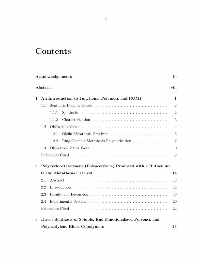
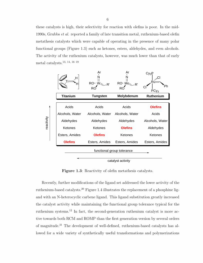
Figure 1.6: Representative cyclic olefin monomers and strain energies.22
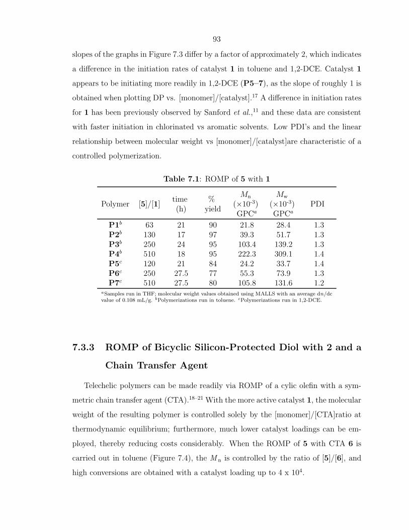
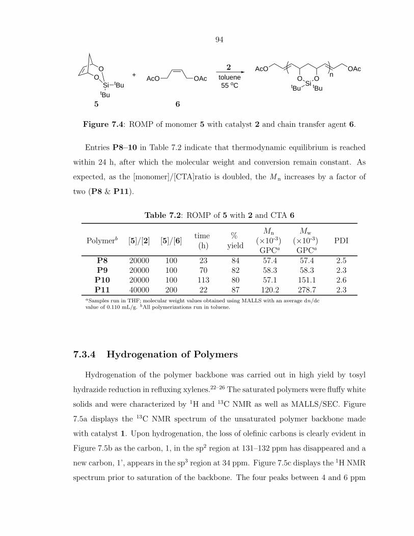
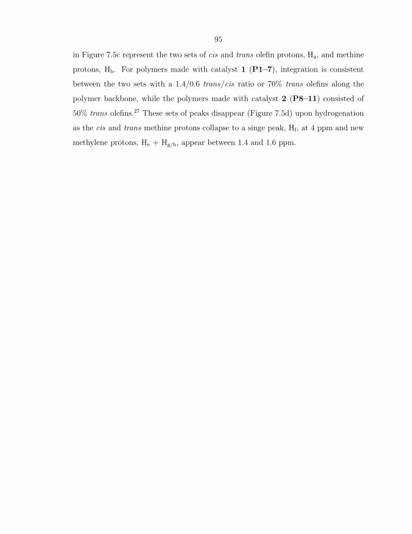
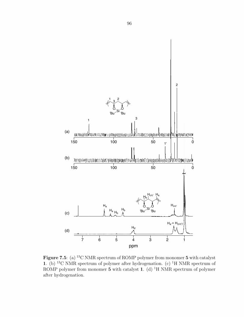
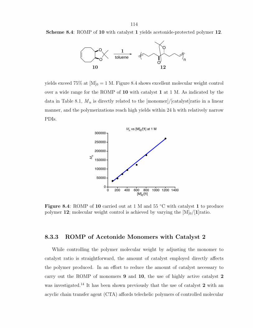
As ROMP can be carried out in solution, facile control of polymer MW can be
achieved in several different ways. For highly strained monomers such as cyclobutene,
norbornene, and oxanorbornene, living polymerization can be attained with fast initi-
ating olefin metathesis catalysts leading to precisely controlled polymer architectures
and MW.15, 27 ROMP has been used to prepare block-copolymers through the se-
quential addition of monomers. Another method to control the MW and architecture
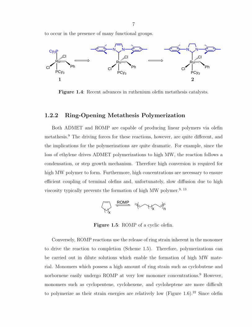
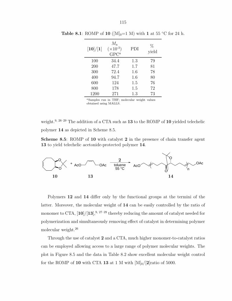
of ROMP polymers is through the use of chain transfer agents (CTAs).23, 24 When
ROMP of a cyclic olefin is carried out in the presence of a symmetric CTA, such as an
acyclic olefin, a linear, telechelic polymer will be formed as illustrated in Scheme 1.1.
Telechelic polymers are end-functionalized polymers that have found application in
cross-linking and polymer network formation, chain-extention processes, and in the
solubilization of materials.28
Scheme 1.1: ROMP in the presence of a CTA to produce a linear, telechelic polymer.
X XXX
x nolefin metathesiscatalystx
CTA
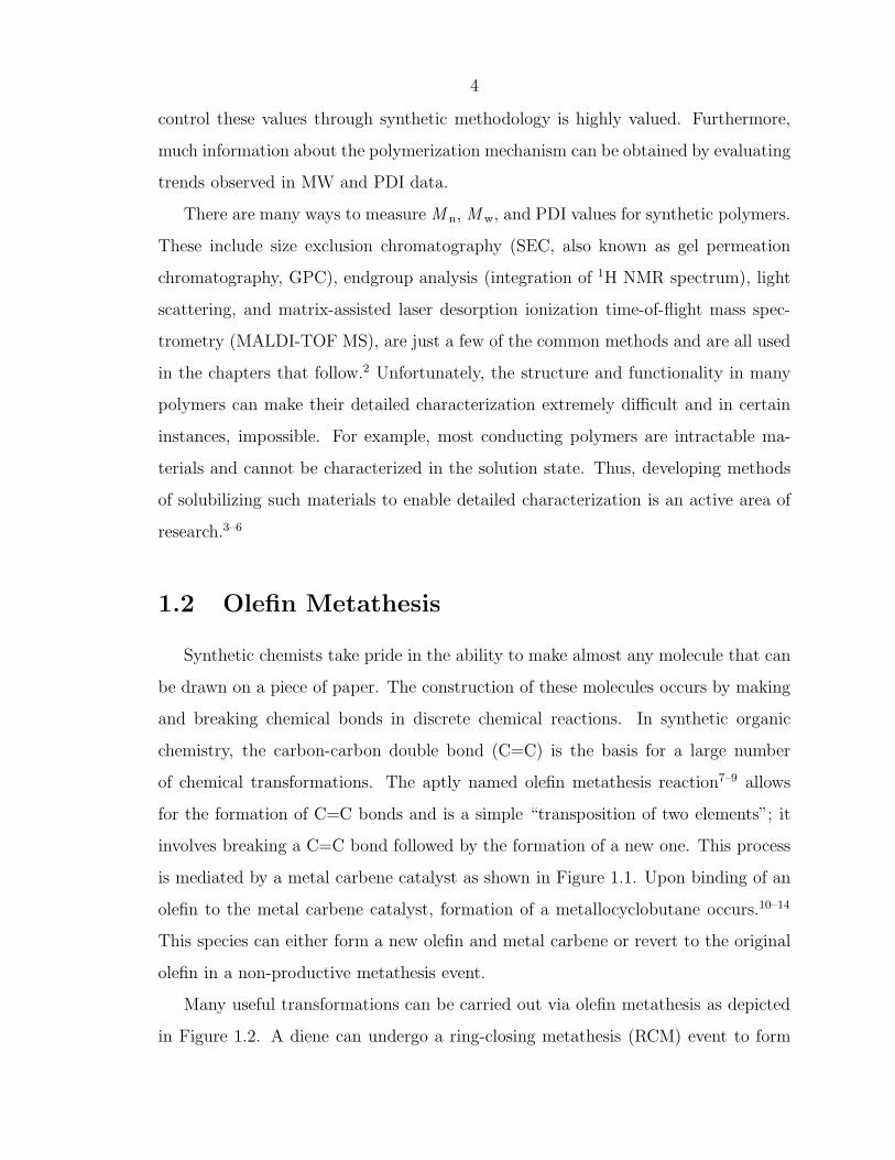
9
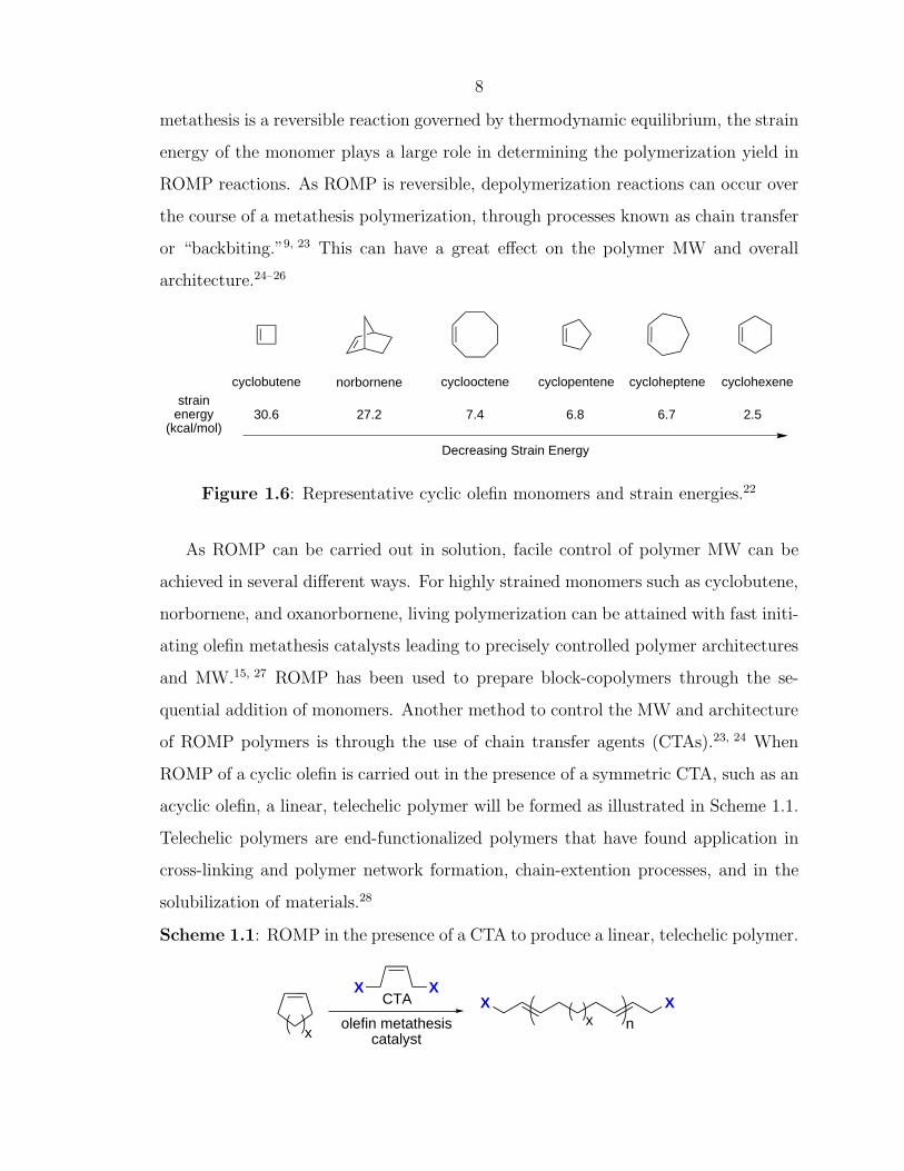
A general reaction mechanism for ROMP with a CTA is outlined in Scheme 1.2.
The propagating polymer chain can react with either a cyclic olefin monomer or with
an acyclic CTA molecule. If a metathesis event occurs with the CTA, the functionality
(X) of the CTA gets transferred to one end of the polymer chain. Later in the
reaction, the other chain end will be formed by reacting with another CTA molecule.
Therefore, at the end of the reaction, all of the chains will have functionality (X)
transferred to both chain ends.∗ Moreover, with the advances in catalyst design over
Scheme 1.2: Mechanism for the synthesis of telechelic polymers by ROMP.
X X XXx n
x
n
[Ru]
R
[Ru]xR
n
X X
[Ru]X
xRm
X
[Ru]X
[Ru]xX
n
X X
<< 1%monofunctional
polymer
perfectly linear polymerfunctionality ~ 2.0
the last decade leading to late transition metal (ruthenium) catalysts, both cyclic and
acyclic olefins bearing polar functional groups can now be employed in ROMP.12 This
has allowed for the synthesis of many new material architectures such as conducting
polymers,29–35 water-soluble polymers,4 and surface-bound polymers,36–38 all of which
will be discussed in the following pages.
∗This requires that a high excess of CTA relative to catalyst is used.23, 24
10
1.3 Objectives of this Work
The research presented in this thesis describes my contributions in the areas of
conducting polymers, surface-inititated polymers, and well-defined polar functional
polymers that are prepared by ROMP. Chapter 2 introduces the synthesis of conduct-
ing polymers via ROMP and illustrates that catalyst activity plays an important role
in the preparation of polymers such as polyacetylene. The use of late transition metal
olefin metathesis catalysts such as ruthenium to form polyacetylene (Chapter 2) was
extended to form telechelic, solubilized polyenes and polyacetylene block-copolymers
through the use of chain transfer agents; this work is discussed in Chapter 3. The use
of ROMP in surface-initiated polymerization is discussed in Chapters 4 and 5. In a
collaboration with Dr. Agnes Juang and Prof. Nathan Lewis (Caltech), organic over-
layers consisting of polynorbornene were grown from a Si (111) surface (Chapter 4).
The ROMP polymer was covalently attached to the silicon surface with a direct Si-C
linkage instead of through the traditional Si/SiO2 linkers previously employed. This
concept was further explored in a collaboration with Mr. Isaac Rutenberg (also a
member of the Grubbs group at Caltech) and Dr. Zhenan Bao (Lucent Technologies)
in order to prepare top-contact field-effect thin film transistors with a ROMP poly-
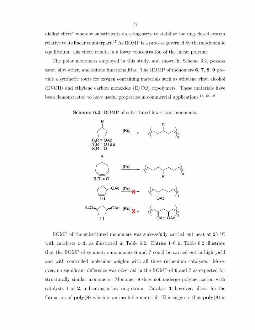
mer as the dielectric layer (Chapter 5). Chapter 6 evaluates the ROMP of low-strain
monomers such as cyclopentene and cycloheptene and discusses the thermodynamic
considerations involved in ROMP. A model for predicting the ability of a cyclic olefin
to undergo ROMP (“ROMPability”) is presented. Novel materials possessing a range
of both polar and apolar functionalities can now be prepared in large scale. These ma-
terials include both telechelic polymers, block-copolymers, and polymers with main-
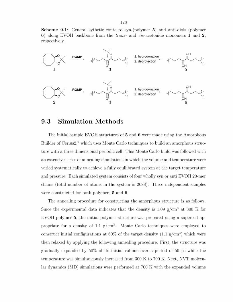
chain functionality. Chapters 7 and 8 describe a synthetic strategy for achieving both
regioregular and stereoregular polymers bearing alcohol functionalities. A set of ra-
tionally designed ethylene vinyl alcohol (EVOH) copolymers allowed for the detailed
study of property–function relationships for functional polymers. Complementary to
the EVOH synthesis by ROMP, Chapter 9 describes some results from a collaborative
effort with Dr. Valeria Molinero (a postdoc in the Goddard group at Caltech) for the
11
computational modeling of regioregular and stereoregular EVOH, and illustrates why
the local polymer structure can effect material properties such as O2 permeability.
12
References Cited
[1] Odian, G. Principles of Polymerization; Wiley & Sons: New York, 3rd ed.; 1991.[2] Cowie, J. M. G. Polymers: Chemistry and physics of modern materials; Chap-
man and Hall: New York, 2nd ed.; 1991.[3] Stelzer, F.; Grubbs, R. H.; Leising, G. Polymer 1991, 32, 1851–1856.[4] Wagaman, M. W.; Grubbs, R. H. Macromolecules 1997, 30, 3978–3985.[5] Knoll, K.; Schrock, R. R. J. Am. Chem. Soc. 1989, 111, 7989–8004.[6] Krouse, S. A.; Schrock, R. R. Macromolecules 1988, 21, 1885–1888.[7] Calderon, N.; Chen, H. Y.; Scott, K. W. Tetrahedron Lett. 1967, 34, 3327–3329.[8] Calderon, N. Acc. Chem. Res. 1972, 5, 127–132.[9] Ivin, K. J.; Mol, J. C. Olefin Metathesis and Metathesis Polymerization; Aca-
demic Press: London, 1997.[10] Herisson, J. L.; Chauvin, Y. Makromol. Chem. 1971, 141, 161.[11] Sanford, M. S.; Ulman, M.; Grubbs, R. H. J. Am. Chem. Soc. 2001, 123,
749–750.[12] Sanford, M. S.; Love, J. A.; Grubbs, R. H. J. Am. Chem. Soc. 2001, 123,
6543–6554.[13] Grubbs, R. H., Ed.; Handbook of Metathesis; Wiley-VCH: Weinheim, 2003.[14] Trnka, T. M.; Grubbs, R. H. Acc. Chem. Res. 2001, 34, 18–29.[15] Schrock, R. R.; Krouse, S. A.; Knoll, K.; Feldman, J.; Murdzek, J. S.;
Yang, D. C. J. Mol. Catal. 1988, 46, 243–253.[16] Nguyen, S. T.; Grubbs, R. H.; Ziller, J. W. J. Am. Chem. Soc. 1993, 115,
9858–9859.[17] Schwab, P.; France, M. B.; Ziller, J. W.; Grubbs, R. H. Angew. Chem., Int.
Ed. 1995, 34, 2039–2041.[18] Schwab, P.; Grubbs, R. H.; Ziller, J. W. J. Am. Chem. Soc. 1996, 118, 100–110.[19] Dias, E. L.; Nguyen, S. T.; Grubbs, R. H. J. Am. Chem. Soc. 1997, 119,
3887–3897.[20] Scholl, M.; Ding, S.; Lee, C. W.; Grubbs, R. H. Org. Lett. 1999, 1, 953–956.[21] Bielawski, C. W.; Grubbs, R. H. Angew. Chem., Int. Ed. 2000, 39, 2903–2906.[22] Schleyer, P. v. R.; Williams, J. E.; Blanchard, K. R. J. Am. Chem. Soc. 1970,
92, 2377–2386.[23] Hillmyer, M. A.; Grubbs, R. H. Macromolecules 1993, 26, 872–874.[24] Hillmyer, M. A.; Grubbs, R. H. Macromolecules 1995, 28, 8662–8667.[25] Hillmyer, M. A.; Nguyen, S. T.; Grubbs, R. H. Macromolecules 1997, 30,
718–721.
13
[26] Bielawski, C. W.; Scherman, O. A.; Grubbs, R. H. Polymer 2001, 42, 4939–4945.
[27] Choi, T. L.; Grubbs, R. H. Angew. Chem., Int. Ed. 2003, 42, 1743–1746.[28] Jerome, R.; Henrioullegranville, M.; Boutevin, B.; Robin, J. J. Prog. Polym.
Sci. 1991, 16, 837–906.[29] Klavetter, F. L.; Grubbs, R. H. J. Am. Chem. Soc. 1988, 110, 7807–7813.[30] Klavetter, F. L.; Grubbs, R. H. Synth. Met. 1989, 28, D99–D104.[31] Klavetter, F. L.; Grubbs, R. H. Synth. Met. 1989, 28, D105–D108.[32] Swager, T. M.; Grubbs, R. H. J. Am. Chem. Soc. 1989, 111, 4413–4422.[33] Swager, T. M.; Dougherty, D. A.; Grubbs, R. H. J. Am. Chem. Soc. 1988, 110,
2973–2974.[34] Edwards, J. H.; Feast, W. J. Polymer 1980, 21, 595–596.[35] Scherman, O. A.; Grubbs, R. H. Synth. Met. 2001, 124, 431–434.[36] Weck, M.; Jackiw, J.; Rossi, R.; Weiss, P.; Grubbs, R. H. J. Am. Chem. Soc.
NMR (cis) 132 (trans) 133 (trans)IR major peaks 1015 (trans) 930, 980, 1010, 992,
740 (cis) 765 773, 745aThe shiny, gold appearance of poly(COT) produced from catalyst 2 is most likely due to the hightrans content of the polymer.
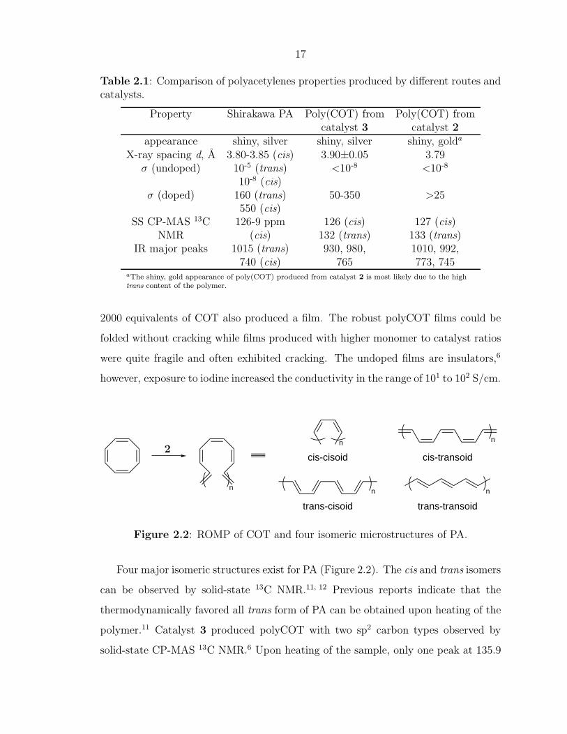
2000 equivalents of COT also produced a film. The robust polyCOT films could be
folded without cracking while films produced with higher monomer to catalyst ratios
were quite fragile and often exhibited cracking. The undoped films are insulators,6
however, exposure to iodine increased the conductivity in the range of 101 to 102 S/cm.
n
n
n n
n
cis-cisoid cis-transoid
trans-cisoid trans-transoid
2
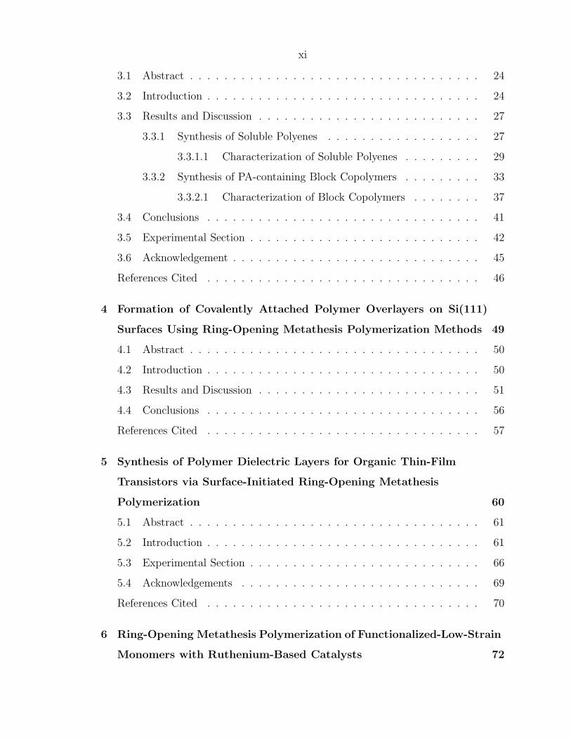
Figure 2.2: ROMP of COT and four isomeric microstructures of PA.
Four major isomeric structures exist for PA (Figure 2.2). The cis and trans isomers
can be observed by solid-state 13C NMR.11, 12 Previous reports indicate that the
thermodynamically favored all trans form of PA can be obtained upon heating of the
polymer.11 Catalyst 3 produced polyCOT with two sp2 carbon types observed by
solid-state CP-MAS 13C NMR.6 Upon heating of the sample, only one peak at 135.9
18
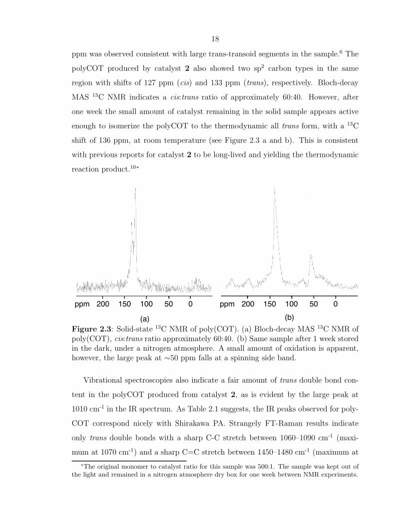
ppm was observed consistent with large trans-transoid segments in the sample.6 The
polyCOT produced by catalyst 2 also showed two sp2 carbon types in the same
region with shifts of 127 ppm (cis) and 133 ppm (trans), respectively. Bloch-decay
MAS 13C NMR indicates a cis:trans ratio of approximately 60:40. However, after
one week the small amount of catalyst remaining in the solid sample appears active
enough to isomerize the polyCOT to the thermodynamic all trans form, with a 13C
shift of 136 ppm, at room temperature (see Figure 2.3 a and b). This is consistent
with previous reports for catalyst 2 to be long-lived and yielding the thermodynamic
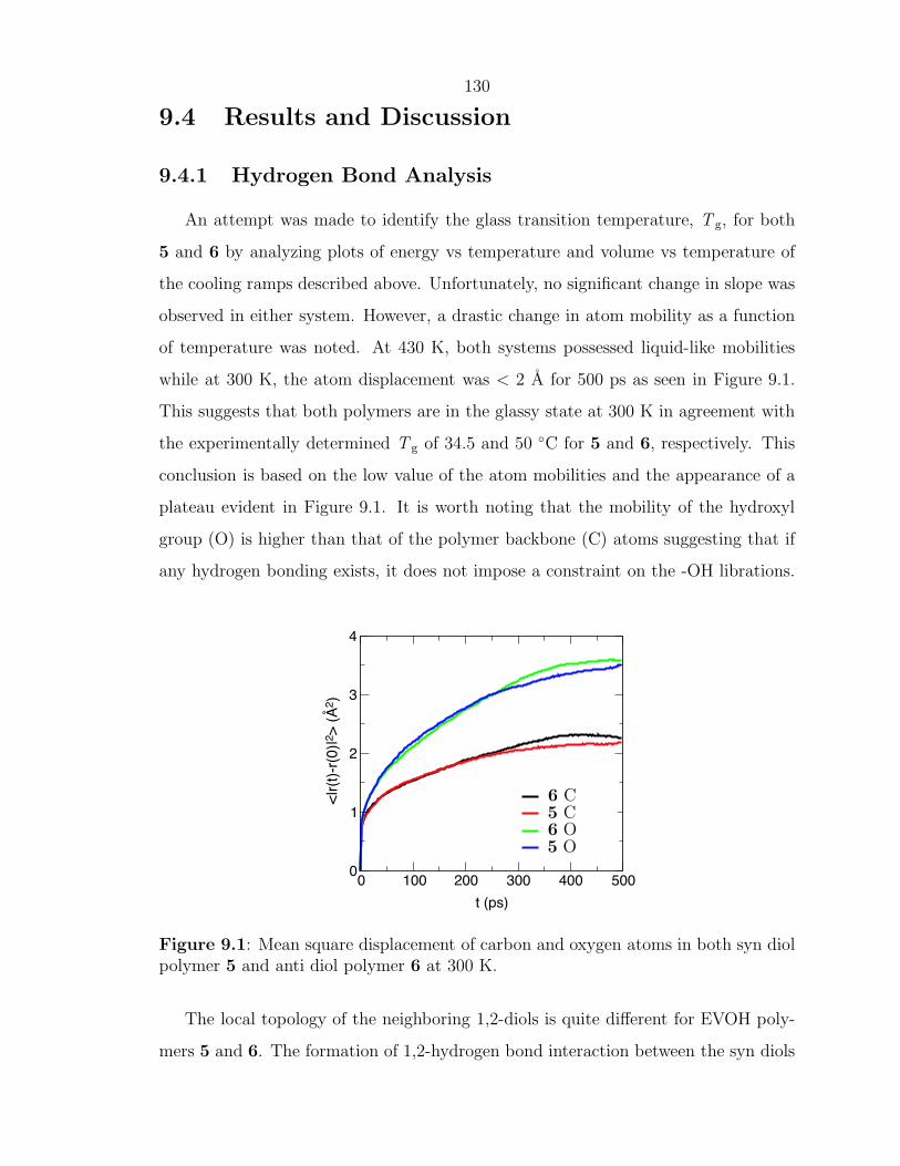
reaction product.10∗
(a) (b)
200ppm 150 100 50 0200ppm 150 100 50 0
Figure 2.3: Solid-state 13C NMR of poly(COT). (a) Bloch-decay MAS 13C NMR ofpoly(COT), cis:trans ratio approximately 60:40. (b) Same sample after 1 week storedin the dark, under a nitrogen atmosphere. A small amount of oxidation is apparent,however, the large peak at ∼50 ppm falls at a spinning side band.
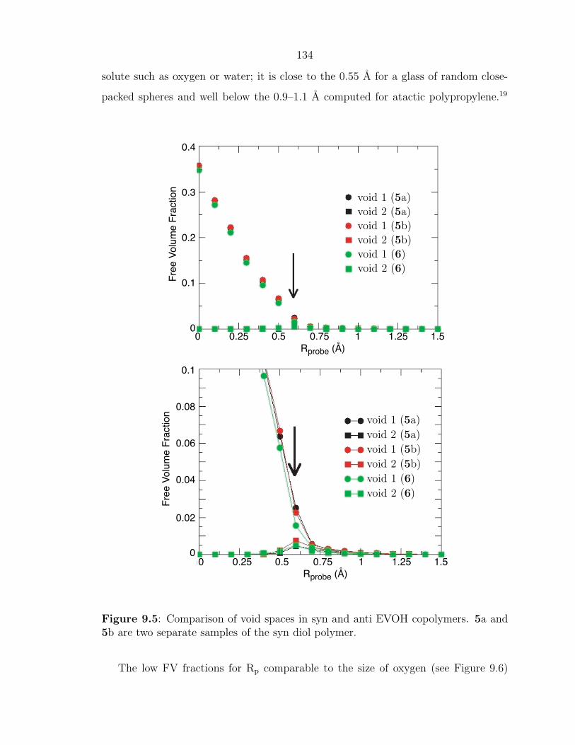
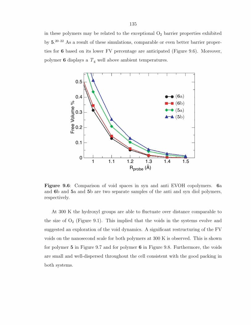
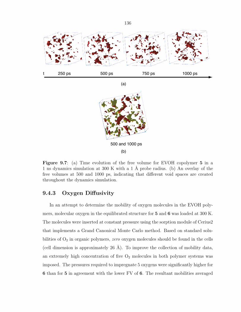
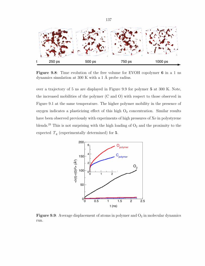
Vibrational spectroscopies also indicate a fair amount of trans double bond con-
tent in the polyCOT produced from catalyst 2, as is evident by the large peak at
1010 cm-1 in the IR spectrum. As Table 2.1 suggests, the IR peaks observed for poly-
COT correspond nicely with Shirakawa PA. Strangely FT-Raman results indicate
only trans double bonds with a sharp C-C stretch between 1060–1090 cm-1 (maxi-
mum at 1070 cm-1) and a sharp C=C stretch between 1450–1480 cm-1 (maximum at
∗The original monomer to catalyst ratio for this sample was 500:1. The sample was kept out of
the light and remained in a nitrogen atmosphere dry box for one week between NMR experiments.
19
1460 cm-1). This lower Raman shift for the C=C stretch is indicative of longer aver-
age conjugation length as compared to polyCOT produced by 3 which Klavetter et
al. observed between 1463–1531 cm-1.6, 13 FT-IR and solid-state 13C NMR certainly
indicate ample cis double bond content in the polyCOT while the FT-Raman spec-
trum is virtually void of cis character. While this may be due to selective resonance
enhancements that can obscure the cis peak around 1250 cm−1, we are unable to
definitively say why the cis peak is omitted in the raman spectra.14
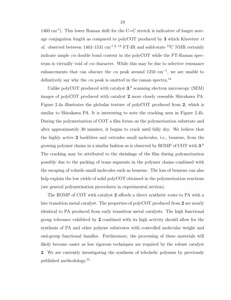
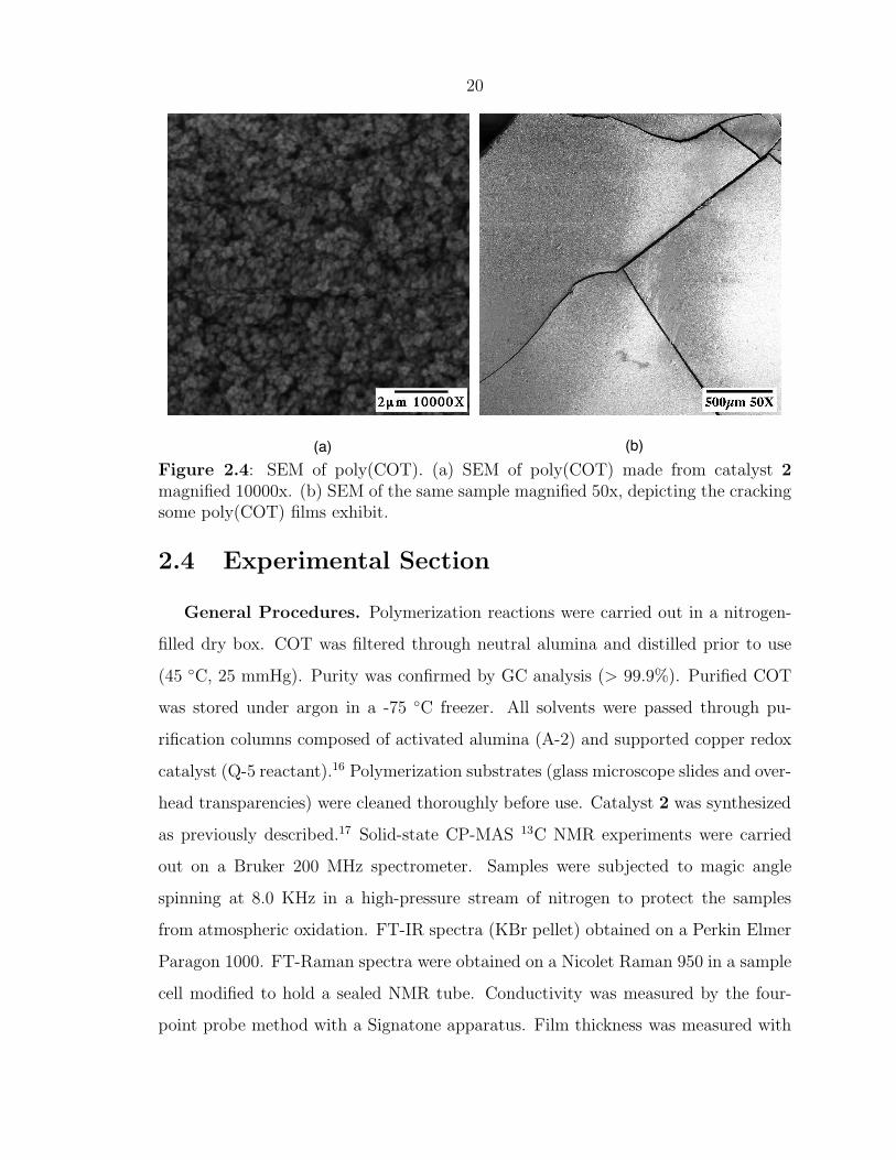
Unlike polyCOT produced with catalyst 3,6 scanning electron microscopy (SEM)
images of polyCOT produced with catalyst 2 more closely resemble Shirakawa PA.
Figure 2.4a illustrates the globular texture of polyCOT produced from 2, which is
similar to Shirakawa PA. It is interesting to note the cracking seen in Figure 2.4b.
During the polymerization of COT a film forms on the polymerization substrate and
after approximately 30 minutes, it begins to crack until fully dry. We believe that
the highly active 2 backbites and extrudes small molecules, i.e., benzene, from the
growing polymer chains in a similar fashion as is observed by ROMP of COT with 3.6
The cracking may be attributed to the shrinkage of the film during polymerization
possibly due to the packing of trans segments in the polymer chains combined with
the escaping of volatile small molecules such as benzene. The loss of benzene can also
help explain the low yields of solid polyCOT obtained in the polymerization reactions
(see general polymerization procedures in experimental section).
The ROMP of COT with catalyst 2 affords a direct synthetic route to PA with a
late transition metal catalyst. The properties of polyCOT produced from 2 are nearly
identical to PA produced from early transition metal catalysts. The high functional
group tolerance exhibited by 2 combined with its high activity should allow for the
synthesis of PA and other polyene substrates with controlled molecular weight and
end-group functional handles. Furthermore, the processing of these materials will
likely become easier as less rigorous techniques are required by the robust catalyst
2. We are currently investigating the synthesis of telechelic polyenes by previously
published methodology.15
20
(a) (b)
Figure 2.4: SEM of poly(COT). (a) SEM of poly(COT) made from catalyst 2magnified 10000x. (b) SEM of the same sample magnified 50x, depicting the crackingsome poly(COT) films exhibit.
2.4 Experimental Section
General Procedures. Polymerization reactions were carried out in a nitrogen-
filled dry box. COT was filtered through neutral alumina and distilled prior to use
(45 ◦C, 25 mmHg). Purity was confirmed by GC analysis (> 99.9%). Purified COT
was stored under argon in a -75 ◦C freezer. All solvents were passed through pu-
rification columns composed of activated alumina (A-2) and supported copper redox
catalyst (Q-5 reactant).16 Polymerization substrates (glass microscope slides and over-
head transparencies) were cleaned thoroughly before use. Catalyst 2 was synthesized
as previously described.17 Solid-state CP-MAS 13C NMR experiments were carried
out on a Bruker 200 MHz spectrometer. Samples were subjected to magic angle
spinning at 8.0 KHz in a high-pressure stream of nitrogen to protect the samples
from atmospheric oxidation. FT-IR spectra (KBr pellet) obtained on a Perkin Elmer
Paragon 1000. FT-Raman spectra were obtained on a Nicolet Raman 950 in a sample
cell modified to hold a sealed NMR tube. Conductivity was measured by the four-
point probe method with a Signatone apparatus. Film thickness was measured with
21
a Mitutoyo electronic micrometer. Doping of PA films by I2 vapor were carried out
in a glass schlenk tube which was evacuated and then closed, the films were allowed
to sit under static vacuum for several hours.
Polymerization of COT. In a typical polymerization, approximately 5 mg of
catalyst was placed in a 3 mL vial. 0.5 mL of COT (approximately 500 equivalents)
was then added to the vial by syringe and the solution was swirled gently. Within
10–30 seconds the yellow solution suddenly turned dark red and subsequently purple.
The purplish solution was then transferred to a pre-weighed polymerization substrate
by pipet and allowed to polymerize under ambient temperature and pressure. The
solution gelled and hardened within minutes yielding a shiny, black film, intractable
in common solvents. The film was gently washed with a small amount of methanol to
remove any unreacted monomer. The yields in these polymerization reactions ranged
from 15-30% based on weight differential of the polymer substrate before and after
deposition of the polyCOT.
22
References Cited
[1] Shirakawa, H.; Ikeda, S. Polym. J. (Tokyo) 1971, 2, 231.[2] Edwards, J. H.; Feast, W. J. Polymer 1980, 21, 595–596.[3] Swager, T. M.; Dougherty, D. A.; Grubbs, R. H. J. Am. Chem. Soc. 1988, 110,
2973–2974.[4] Swager, T. M.; Grubbs, R. H. J. Am. Chem. Soc. 1989, 111, 4413–4422.[5] Korshak, Y. V.; Korshak, V. V.; Kanischka, G.; Hocker, H. Makromol. Chem.,
Rapid Commun. 1985, 6, 685–692.[6] Klavetter, F. L.; Grubbs, R. H. J. Am. Chem. Soc. 1988, 110, 7807–7813.[7] Klavetter, F. L.; Grubbs, R. H. Synth. Met. 1989, 28, D99–D104.[8] Schleyer, P. v. R.; Williams, J. E.; Blanchard, K. R. J. Am. Chem. Soc. 1970,
92, 2377–2386.[9] Allinger, N. L.; Sprague, J. T. J. Am. Chem. Soc. 1972, 94, 5734–5747.
[10] Bielawski, C. W.; Grubbs, R. H. Angew. Chem., Int. Ed. 2000, 39, 2903–2906.[11] Terao, T.; Maeda, S.; Yamabe, T.; Akagi, K.; Shirakawa, H. Chem. Phys. Lett.
1984, 103, 347–351.[12] Maricq, M. M.; Waugh, J. S.; MacDiarmid, A. G.; Shirakawa, H.; Heeger, A. J.
J. Am. Chem. Soc. 1978, 100, 7729–7730.[13] Shibahara, S.; Yamane, M.; Ishikawa, K.; Takezoe, H. Macromolecules 1998,
31, 3756–3758.[14] Kuzmany, H. Phys. Stat. Sol. 1980, 97, 521–531.[15] Bielawski, C. W.; Scherman, O. A.; Grubbs, R. H. Polymer 2001, 42, 4939–
4945.[16] Pangborn, A. B.; Giardello, M. A.; Grubbs, R. H.; Rosen, R. K.; Timmers, F. J.
Organometallics 1996, 15, 1518–1520.[17] Scholl, M.; Ding, S.; Lee, C. W.; Grubbs, R. H. Org. Lett. 1999, 1, 953–956.
23
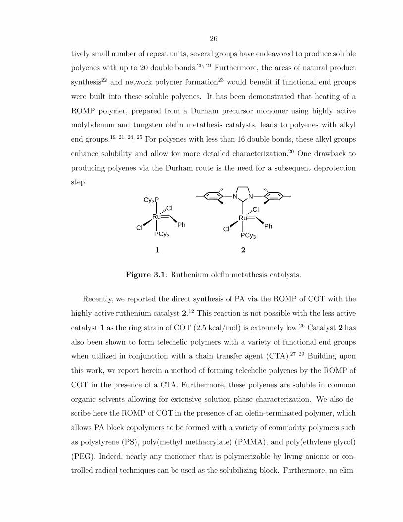
Chapter 3
Direct Synthesis of Soluble,End-Functionalized Polyenes andPolyacetylene Block-Copolymers
This has previously appeared as: Scherman, O. A.; Rutenberg, I. M.; Grubbs, R. H.
Journal of the American Chemical Society, 2003, 125, 8515–8522.
24
3.1 Abstract
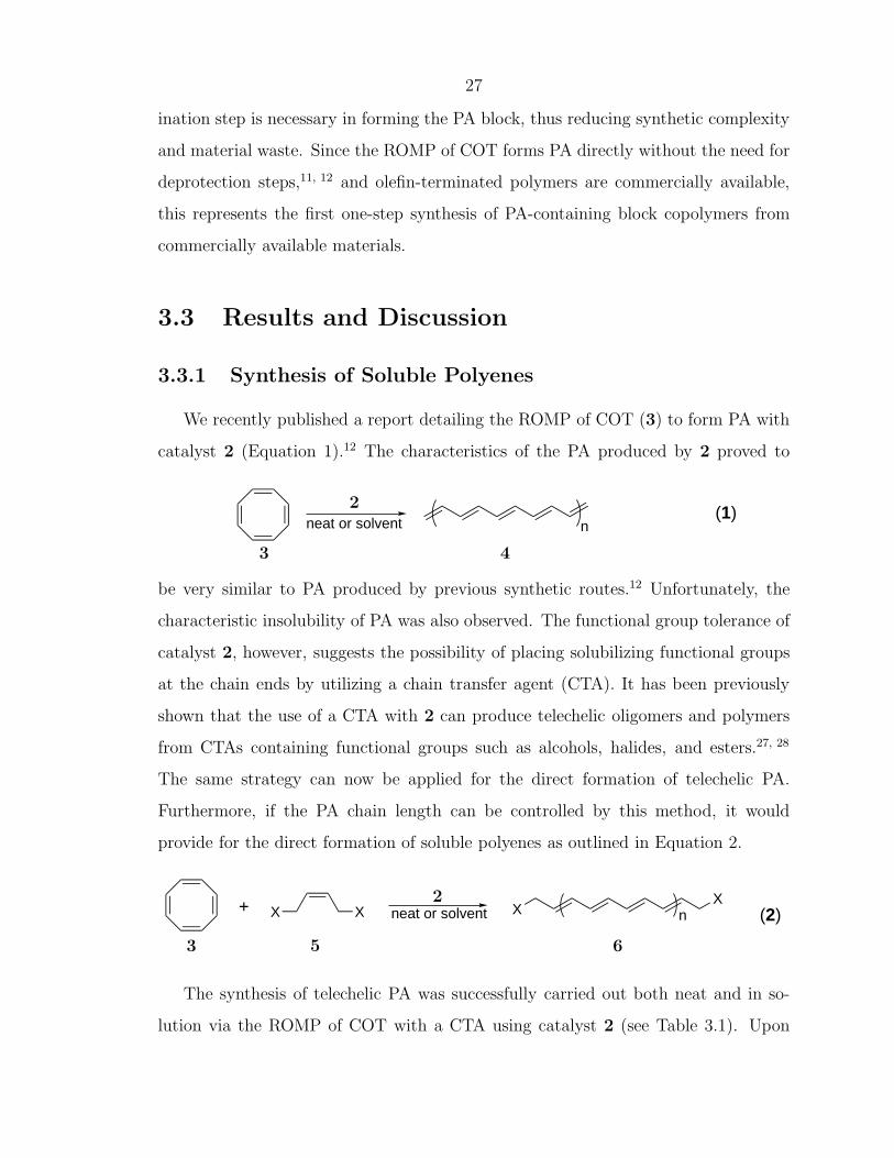
The ring-opening metathesis polymerization (ROMP) of 1,3,5,7-cyclooctatetraene
(COT) in the presence of a chain transfer agent (CTA) with a highly active ruthe-
nium olefin metathesis catalyst resulted in the formation of soluble polyenes. Small
molecule CTAs containing an internal olefin and a variety of functional groups resulted
in soluble telechelic polyenes with up to 20 double bonds. Use of polymeric CTAs
with an olefin terminus resulted in polyacetylene block copolymers. These materials
were subjected to a variety of solution and solid phase characterization techniques
including 1H NMR, UV/vis, and FT-IR spectroscopies, as well as MALDI-TOF MS
and AFM.
3.2 Introduction
Intrinsically conducting polymers (ICP)s are of great interest due to their po-
tential use in a wide variety of applications such as polymer light-emitting diodes
(PLED)s, electrostatic dissipation (ESD) materials, and charge storage devices. As a
consequence of their rigidity, most ICPs are insoluble materials, preventing thorough
characterization and thereby slowing the development of this field. Moreover, the
inherent instability of ICPs and associated processing difficulties create a large bar-
rier for commercialization. In an effort to overcome these obstacles, the development
of a practical synthesis of relatively stable and soluble conducting polymers with a
controlled architecture is important.
The field of conducting polymers was founded upon the discovery of polyacetyl-
ene (PA), the simplest ICP, in the 1970s.1–5 There have since been numerous ac-
counts on the synthesis of PA including the Ziegler-Natta polymerization of acety-
lene,6 the synthesis of precursor polymers followed by thermal evolution of a small
molecule,7, 8 and the ring-opening metathesis polymerization (ROMP) of 1,3,5,7-
cyclooctatetraene (COT).9–12 Despite these developments, applications of PA remain
particularly elusive. Unlike PA, however, three decades of research involving other
25
ICPs such as polyaniline, poly(1,4-phenylenevinylene) (PPV), polypyrrole (PPy), and
polythiopene (PTh) has resulted in their commercialization in applications such as
anti-fouling coatings13 and electrodes in batteries and capacitors.14
Since most ICPs are completely insoluble in organic solvents, several strategies
have been employed to address this problem. One common approach is to add sub-
stitution along the polymer backbone thereby disturbing alignment between polymer
chains and allowing for the penetration of solvating molecules. This approach has
worked well for improving the solubilities of PPV and PTh in the forms of poly[2-
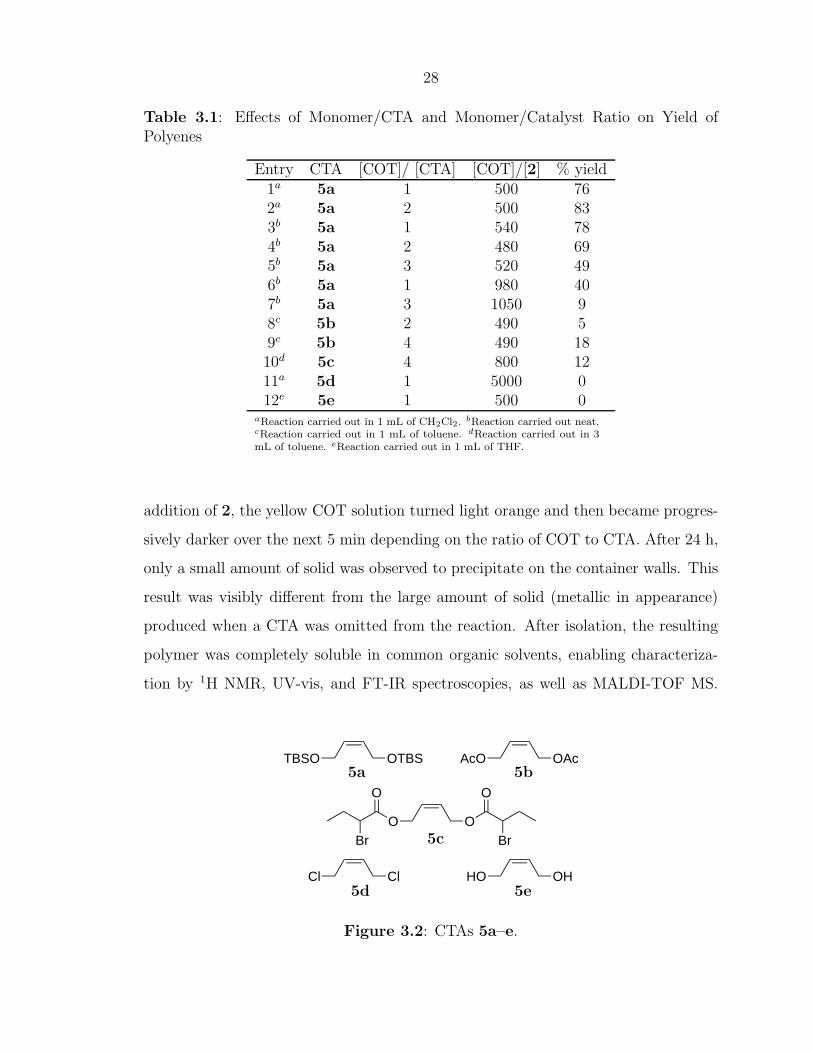
aReaction carried out in 1 mL of CH2Cl2. bReaction carried out neat.cReaction carried out in 1 mL of toluene. dReaction carried out in 3mL of toluene. eReaction carried out in 1 mL of THF.
addition of 2, the yellow COT solution turned light orange and then became progres-
sively darker over the next 5 min depending on the ratio of COT to CTA. After 24 h,
only a small amount of solid was observed to precipitate on the container walls. This
result was visibly different from the large amount of solid (metallic in appearance)
produced when a CTA was omitted from the reaction. After isolation, the resulting
polymer was completely soluble in common organic solvents, enabling characteriza-
tion by 1H NMR, UV-vis, and FT-IR spectroscopies, as well as MALDI-TOF MS.
TBSO OTBS AcO OAc
Cl Cl HO OH
O OBr
OO
Br
5a 5b
5c
5d 5e
Figure 3.2: CTAs 5a–e.
29
Attempts to use CTAs such as 5d and 5e were not successful (Figure 3.2). While
no solids precipitated during the ROMP of COT with CTA 5d, 1H NMR spectroscopy
of the crude reaction mixture showed very little polyene and no material could be
isolated (entry 11). Immiscibility of COT and 5e prevented neat polymerization and
required solvents such as THF for ROMP in solution. Unfortunately, THF has been
shown to dramatically decrease the rate of ROMP,11 and no desired polyene product
was observed in the 1H NMR spectrum of the crude reaction mixture (entry 12).
As a consequence of the loss of material at each stage of preparation, obtaining
the polyenes in high yield was somewhat difficult. Some polyene product was simply
lost upon repetitive centrifuge/decant/wash cycles, while shorter polyene chains were
most likely soluble in the MeOH washes. Entries 1 and 2 in Table 3.1 show that for
ROMP carried out in solution, increasing the amount of COT relative to CTA 5a has
a very minimal effect on the yield of polyene 6a. When the corresponding reactions
are carried out neat (entries 3-5, Table 3.1), a decrease in yield of 6a is observed
with a decrease in the amount of CTA 5a. This trend is likely due to insoluble PA
chains precipitating out of solution when too few chain transfer groups are present
to attenuate the molecular weight. When the amount of COT relative to catalyst 2
is increased to 1000:1 (entries 6 and 7, Table 3.1), the yields decrease substantially.
This observation is likely due to the incomplete initiation of catalyst 230 which would
result in a “true” monomer to catalyst ratio far in excess of 1000. Finally, although it
does not lead to chain termination, backbiting of catalyst 2 onto the growing polyene
chain has previously been shown to eliminate benzene.12 As benzene is not metathesis
active, backbiting essentially removes monomer from the reaction.
3.3.1.1 Characterization of Soluble Polyenes
The loss of monomer over the course of the reaction because of backbiting also ev-
idently hinders our attempt to control the molecular weight of the polyenes by adjust-
ing the ratio of COT to CTA. Previous reports of ROMP reactions with catalyst 2 and
a CTA have shown that molecular weight is dictated by the ratio of [monomer]:[CTA]if
the reaction is allowed to reach thermodynamic equilibrium.27, 28, 31 This result was
30
not found to be the case for COT. While accurate molecular weights and distributions
could not be obtained for the polyenes, 1H NMR spectroscopy as well as MALDI-
TOF MS data indicated average chain lengths of around 10–13 double bonds for all
reactions and did not vary with the ratio of COT:CTA. The average chain length
of the isolated polyenes, however, may be misleading. When a higher COT to CTA
ratio is employed, more polyene chains reach lengths that render them insoluble. For
lower ratios, shorter, MeOH-soluble polyene chains are favored. As a result of likely
fractionation of smaller and longer chains during workup, regardless of the starting
COT to CTA ratio, the isolated polyene chains are heavily weighted to an average
of 10–13 double bonds. Of course, the backbiting of 2 might be attenuated by de-
creasing the reaction temperature; however, if the polymerization of COT occurred
without significant backbiting with a CTA molecule, an insoluble PA chain would
result. Hence, in the direct synthesis of polyenes 6 with catalyst 2, the ability to
control molecular weight is limited.
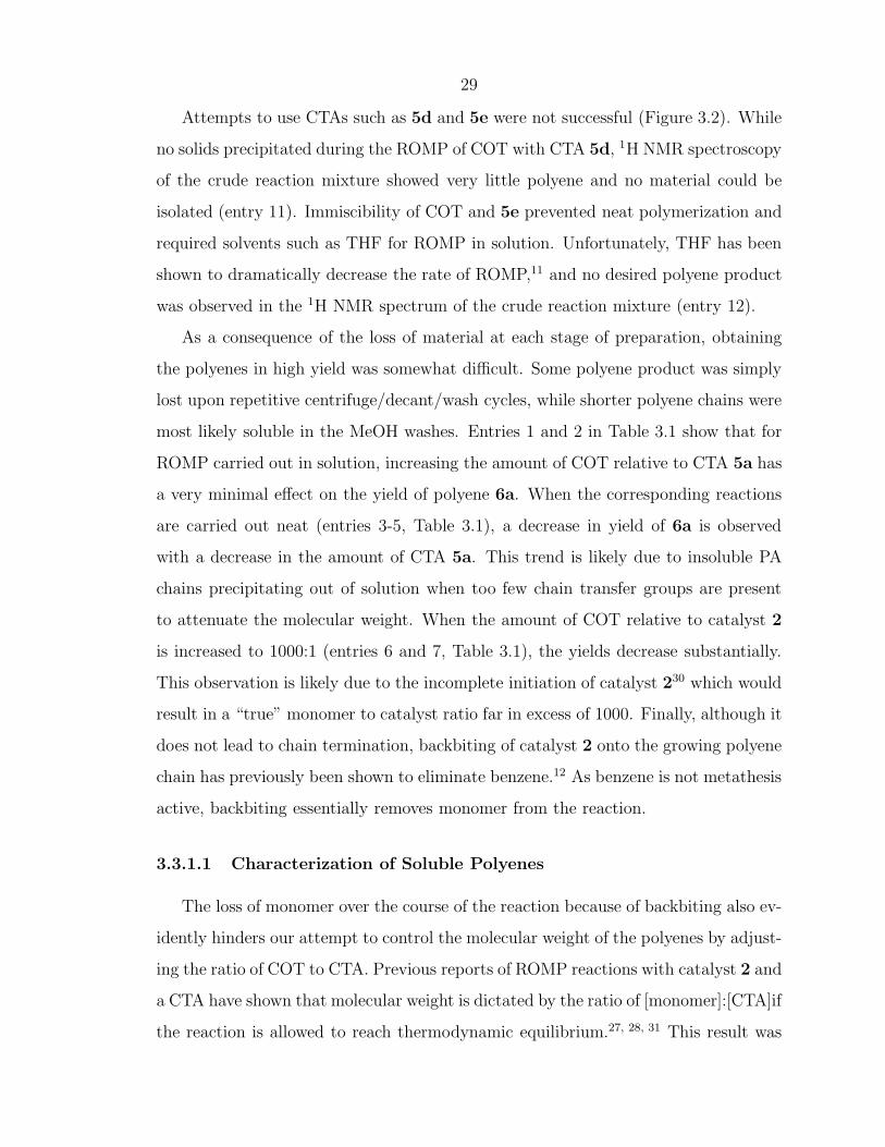
The solution phase 1H NMR spectrum of polyene 6a (Figure 3.3) clearly shows
signals corresponding to the backbone protons of the telechelic polyene between δ=6–
7 ppm, which are characteristically shifted downfield due to the highly conjugated
segment of olefins. The allylic CH2 protons give rise to peaks around δ=4.2 ppm
and the tert-butyl and methyl protons of the silane protecting group (from CTA 5a)
correspond to singlets at δ=0.9 and 0.05 ppm, respectively. The absense of a singlet
at δ=5.79 ppm suggests that all of the unreacted COT was successfully removed
from the polyene product. Integration of the methylene and polyene backbone peaks
suggests an average of 10 double bonds for the sample, which is consistent with the
MALDI-TOF MS data presented below.
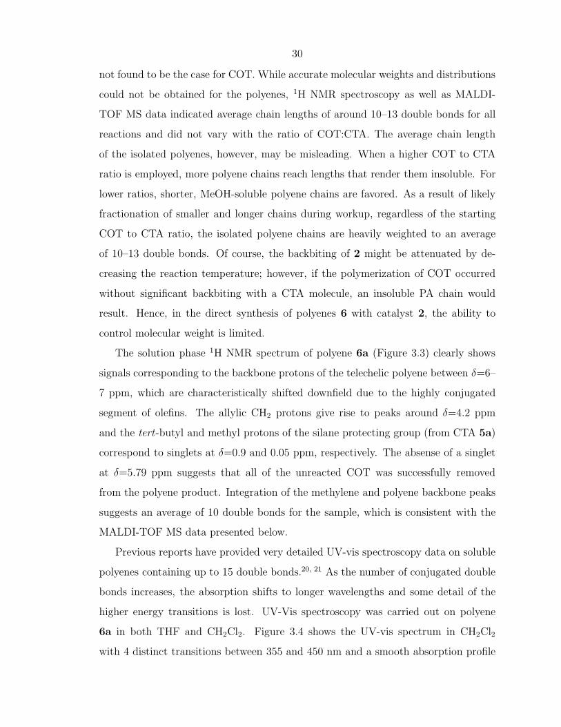
Previous reports have provided very detailed UV-vis spectroscopy data on soluble
polyenes containing up to 15 double bonds.20, 21 As the number of conjugated double
bonds increases, the absorption shifts to longer wavelengths and some detail of the
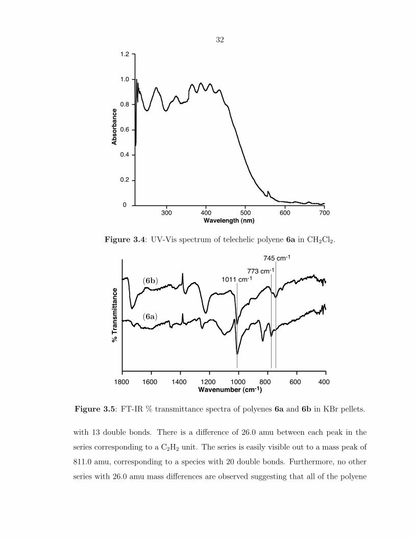
higher energy transitions is lost. UV-Vis spectroscopy was carried out on polyene
6a in both THF and CH2Cl2. Figure 3.4 shows the UV-vis spectrum in CH2Cl2
with 4 distinct transitions between 355 and 450 nm and a smooth absorption profile
31
8 7 6 5 4 3 2 1 0 -1ppm δ
Ha
CHDCl2
Hd
H2O
Hb
Hc
}O
n
OSi
Si
Ha Hd
Hc
Hb
Figure 3.3: 1H NMR spectrum of telechelic polyene 6a in CD2Cl2.
extending past 500 nm. These transitions are consistent with a polyene composed of
10 to 20 double bonds.20
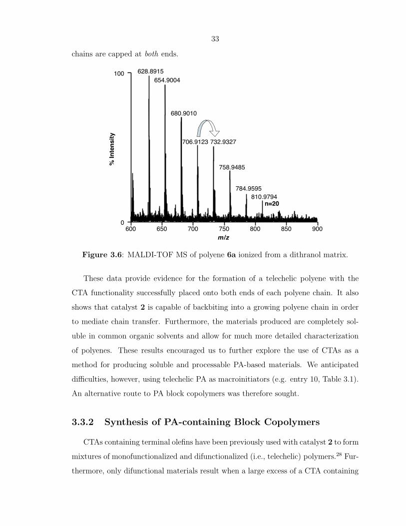
Infrared spectroscopy was also carried out on telechelic polyenes 6a and 6b. Figure
3.5 displays the FT-IR spectra for both telechelic polyenes. The bands at 745, 773,
and 1011 cm-1 are visible in both polyene spectra and are conserved from the IR
spectrum of poly(COT).12 The peak at 743 cm-1 can be attributed to the cis C-
H out-of-plane vibrational mode while the peak 1011 cm-1 is due to the trans C-
H mode.32 The presence of a much larger trans peak at 1011 cm-1 supports the
mechanism of trans-selective catalyst 2 backbiting into the polymer chain to attach
the endgroups and form telechelic polymers or to simply isomerize cis olefins to their
trans counterparts.
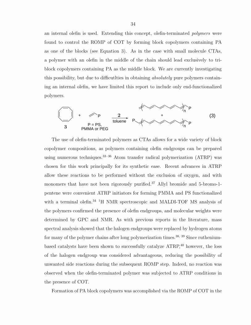
Finally, mass spectrometry was carried out on the telechelic polyenes. Figure 3.6
shows the MALDI-TOF spectrum for 6a acquired from a dithranol matrix. The first
labeled peak with a mass of 628.9 Da corresponds exactly to telechelic polyene 6a
32
300 400 500 600 7000
0.2
0.4
0.6
0.8
1.0
1.2
Wavelength (nm)
Ab
so
rban
ce
Figure 3.4: UV-Vis spectrum of telechelic polyene 6a in CH2Cl2.
9 5 1000 orange 20 9b9 20 1000 deep red 58 9c9 40 1000 black 52 9d10 1 500 dark red 62 10a10 4 1600 brown/black 39 10b10 7 1400 brown/black 28 10c10 20 4000 brown/black 22 10d11 20 4000 brown 36 11a
aCalculated based on total mass of reactants and recovered product. bAll reactions were carriedout in toluene with [COT]0=0.2 M unless otherwise noted. c[COT]0=1.1 M. d[COT]0=0.03 M.
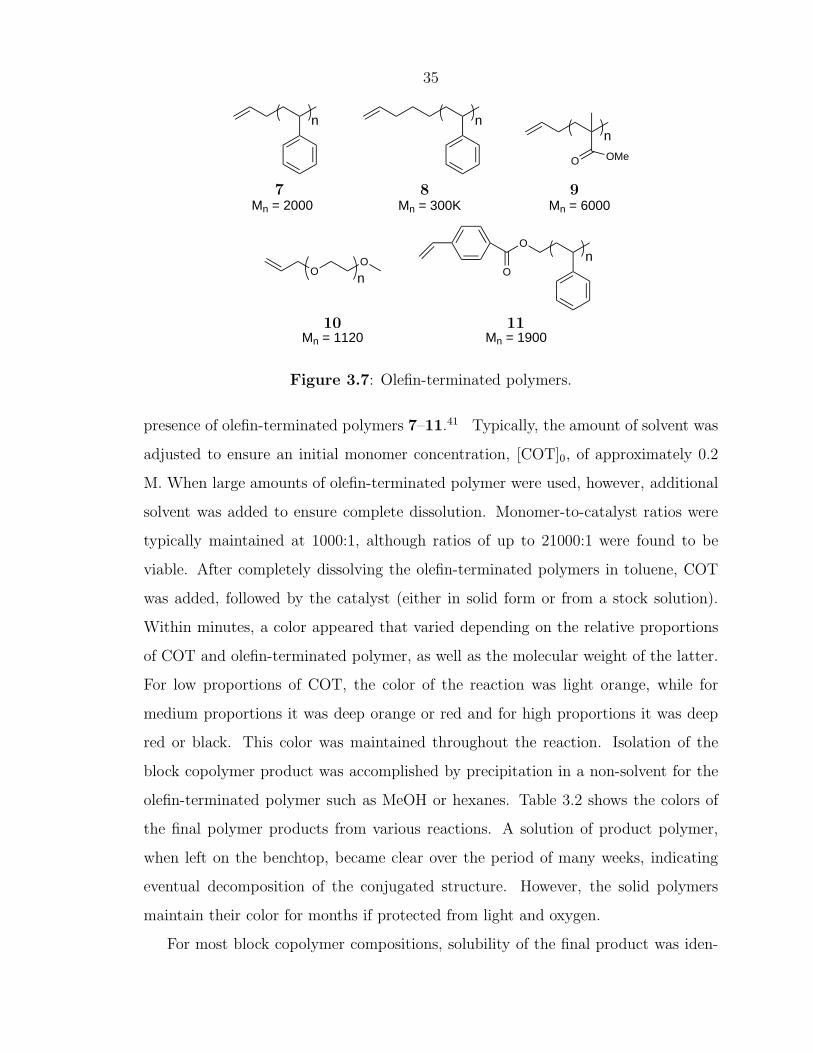
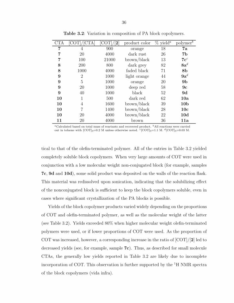
tical to that of the olefin-terminated polymer. All of the entries in Table 3.2 yielded
completely soluble block copolymers. When very large amounts of COT were used in
conjunction with a low molecular weight non-conjugated block (for example, samples
7c, 9d and 10d), some solid product was deposited on the walls of the reaction flask.
This material was redissolved upon sonication, indicating that the solubilizing effect
of the nonconjugated block is sufficient to keep the block copolymers soluble, even in
cases where significant crystallization of the PA blocks is possible.
Yields of the block copolymer products varied widely depending on the proportions
of COT and olefin-terminated polymer, as well as the molecular weight of the latter
(see Table 3.2). Yields exceeded 80% when higher molecular weight olefin-terminated
polymers were used, or if lower proportions of COT were used. As the proportion of
COT was increased, however, a corresponding increase in the ratio of [COT]/[2] led to
decreased yields (see, for example, sample 7c). Thus, as described for small molecule
CTAs, the generally low yields reported in Table 3.2 are likely due to incomplete
incorporation of COT. This observation is further supported by the 1H NMR spectra
of the block copolymers (vida infra).
37
3.3.2.1 Characterization of Block Copolymers
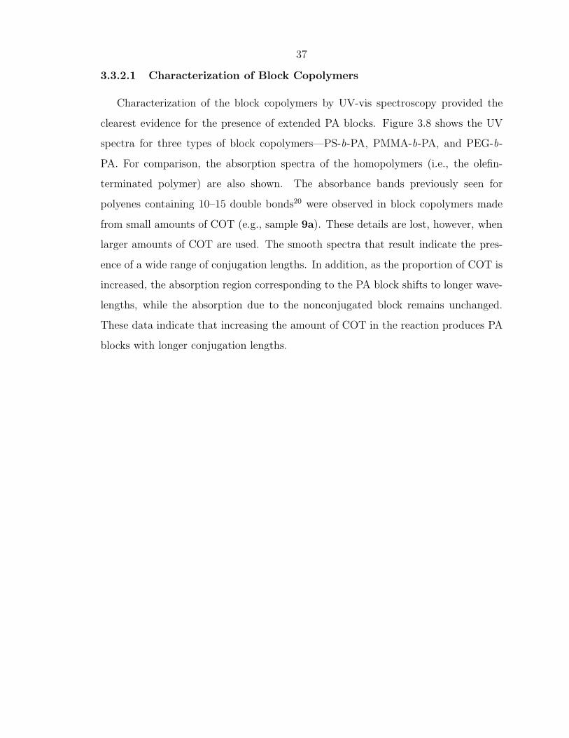
Characterization of the block copolymers by UV-vis spectroscopy provided the
clearest evidence for the presence of extended PA blocks. Figure 3.8 shows the UV
spectra for three types of block copolymers—PS-b-PA, PMMA-b-PA, and PEG-b-
PA. For comparison, the absorption spectra of the homopolymers (i.e., the olefin-
terminated polymer) are also shown. The absorbance bands previously seen for
polyenes containing 10–15 double bonds20 were observed in block copolymers made
from small amounts of COT (e.g., sample 9a). These details are lost, however, when
larger amounts of COT are used. The smooth spectra that result indicate the pres-
ence of a wide range of conjugation lengths. In addition, as the proportion of COT is
increased, the absorption region corresponding to the PA block shifts to longer wave-
lengths, while the absorption due to the nonconjugated block remains unchanged.
These data indicate that increasing the amount of COT in the reaction produces PA
To show that PA is covalently attached to the olefin terminated polymers in these
reactions, the ROMP of COT was carried out in the presence of a bis(hydroxy)-
teminated PEG. A significant amount of insoluble, black solid formed during the
reaction. This solid was removed by filtration, and the remaining polymer product
(white) was isolated by precipitation. The UV-vis spectrum of the resulting polymer
is shown in Figure 3.8b (sample 10e). The lack of absorbance above 320 nm indicates
that no PA was present in the product.
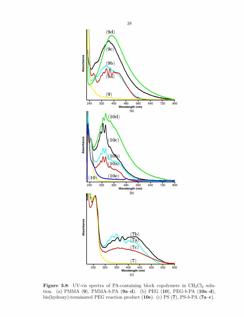
Characteristic IR absorption bands of polyCOT produced with catalyst 2 include
1010, 992, 930, 773, and 745 cm-1.12 Unfortunately, absorption from the noncon-
jugated polymer segments often obscured these absorption bands in the PA block
copolymers. For PMMA-b-PA, however, absorption of the PA segment at 1012 cm-1
is clearly visible and overlays with the absorption spectra of the olefin-terminated
homopolymer (see Figure 3.9).
1300 1200 1100 1000 900 800 700Wavenumber (cm-1)
% T
ran
sm
itta
nc
e
1012 cm-1
(9c)
(9)
Figure 3.9: FT-IR spectra of 9 and 9c.
40
For samples of PMMA-b-PA and PEG-b-PA, it was possible to observe character-
istic peaks in the polyene region of the 1H NMR spectra that appeared very similar
to the peaks shown in Figure 3.3.42 In general, integration of the polyene region
indicated far smaller PA blocks than would be expected from the ratio of COT to
olefin-terminated polymer. For example, integration for sample 9b showed an aver-
age of four or fewer (–C=C–) units per polymer chain, whereas 20 (–C=C–) units
would be expected from the initial reactant ratio. As discussed previously, this low
incorporation can be attributed to two likely sources: the ROMP of COT does not
reach completion, and/or benzene formed from backbiting leads to an effective loss
of monomer. In all NMR spectra, however, a significant amount of unreacted olefin
endgroups remained visible after block copolymer formation, indicating that some
polymer chains have no attached PA blocks. This observation makes it very difficult
to speculate on the average conjugation length of the PA blocks.
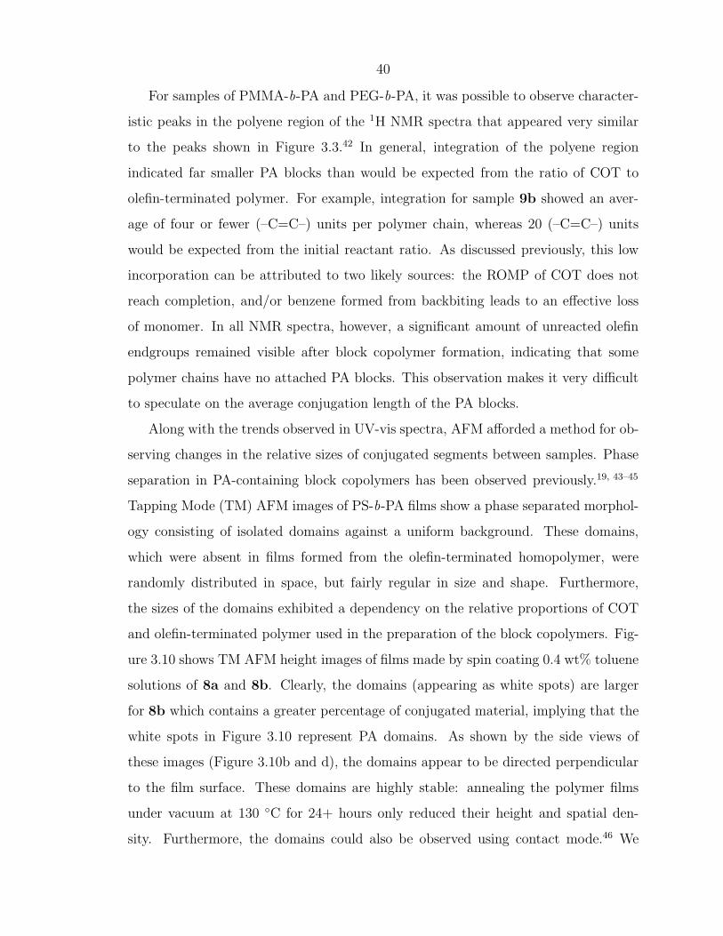
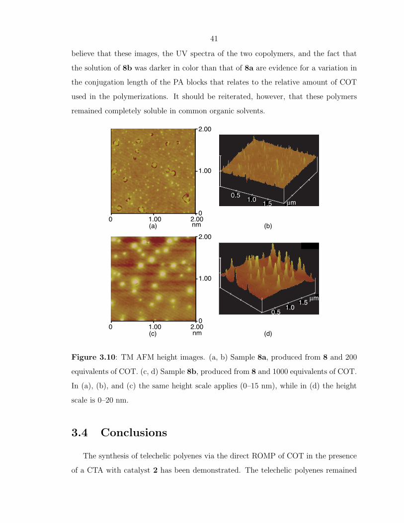
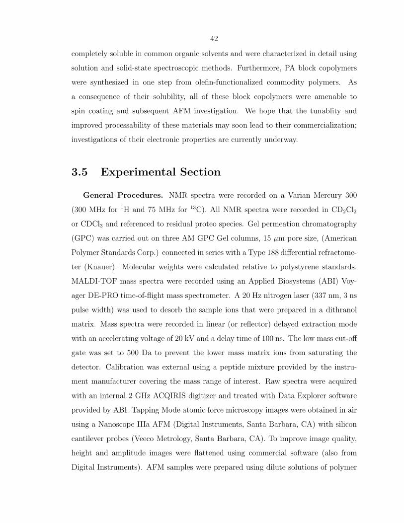
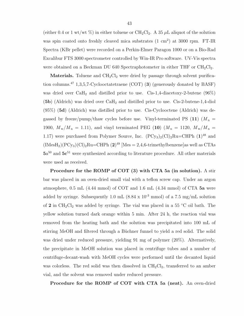
Along with the trends observed in UV-vis spectra, AFM afforded a method for ob-
serving changes in the relative sizes of conjugated segments between samples. Phase
separation in PA-containing block copolymers has been observed previously.19, 43–45
Tapping Mode (TM) AFM images of PS-b-PA films show a phase separated morphol-
ogy consisting of isolated domains against a uniform background. These domains,
which were absent in films formed from the olefin-terminated homopolymer, were
randomly distributed in space, but fairly regular in size and shape. Furthermore,
the sizes of the domains exhibited a dependency on the relative proportions of COT
and olefin-terminated polymer used in the preparation of the block copolymers. Fig-
ure 3.10 shows TM AFM height images of films made by spin coating 0.4 wt% toluene
solutions of 8a and 8b. Clearly, the domains (appearing as white spots) are larger
for 8b which contains a greater percentage of conjugated material, implying that the
white spots in Figure 3.10 represent PA domains. As shown by the side views of
these images (Figure 3.10b and d), the domains appear to be directed perpendicular
to the film surface. These domains are highly stable: annealing the polymer films
under vacuum at 130 ◦C for 24+ hours only reduced their height and spatial den-
sity. Furthermore, the domains could also be observed using contact mode.46 We
41
believe that these images, the UV spectra of the two copolymers, and the fact that
the solution of 8b was darker in color than that of 8a are evidence for a variation in
the conjugation length of the PA blocks that relates to the relative amount of COT
used in the polymerizations. It should be reiterated, however, that these polymers
remained completely soluble in common organic solvents.
µm
µm
1.5
1.5
1.0
1.0
0.5
0.5
0
1.00
2.00
1.000 2.00
1.000 2.000
1.00
2.00
nm
nm(a)
(c)
(b)
(d)
Figure 3.10: TM AFM height images. (a, b) Sample 8a, produced from 8 and 200
equivalents of COT. (c, d) Sample 8b, produced from 8 and 1000 equivalents of COT.
In (a), (b), and (c) the same height scale applies (0–15 nm), while in (d) the height
scale is 0–20 nm.
3.4 Conclusions
The synthesis of telechelic polyenes via the direct ROMP of COT in the presence
of a CTA with catalyst 2 has been demonstrated. The telechelic polyenes remained
42
completely soluble in common organic solvents and were characterized in detail using
solution and solid-state spectroscopic methods. Furthermore, PA block copolymers
were synthesized in one step from olefin-functionalized commodity polymers. As
a consequence of their solubility, all of these block copolymers were amenable to
spin coating and subsequent AFM investigation. We hope that the tunablity and
improved processability of these materials may soon lead to their commercialization;
investigations of their electronic properties are currently underway.
3.5 Experimental Section
General Procedures. NMR spectra were recorded on a Varian Mercury 300
(300 MHz for 1H and 75 MHz for 13C). All NMR spectra were recorded in CD2Cl2
or CDCl3 and referenced to residual proteo species. Gel permeation chromatography
(GPC) was carried out on three AM GPC Gel columns, 15 µm pore size, (American
Polymer Standards Corp.) connected in series with a Type 188 differential refractome-
ter (Knauer). Molecular weights were calculated relative to polystyrene standards.
MALDI-TOF mass spectra were recorded using an Applied Biosystems (ABI) Voy-
ager DE-PRO time-of-flight mass spectrometer. A 20 Hz nitrogen laser (337 nm, 3 ns
pulse width) was used to desorb the sample ions that were prepared in a dithranol
matrix. Mass spectra were recorded in linear (or reflector) delayed extraction mode
with an accelerating voltage of 20 kV and a delay time of 100 ns. The low mass cut-off
gate was set to 500 Da to prevent the lower mass matrix ions from saturating the
detector. Calibration was external using a peptide mixture provided by the instru-
ment manufacturer covering the mass range of interest. Raw spectra were acquired
with an internal 2 GHz ACQIRIS digitizer and treated with Data Explorer software
provided by ABI. Tapping Mode atomic force microscopy images were obtained in air
using a Nanoscope IIIa AFM (Digital Instruments, Santa Barbara, CA) with silicon
cantilever probes (Veeco Metrology, Santa Barbara, CA). To improve image quality,
height and amplitude images were flattened using commercial software (also from
Digital Instruments). AFM samples were prepared using dilute solutions of polymer
43
(either 0.4 or 1 wt/wt %) in either toluene or CH2Cl2. A 35 µL aliquot of the solution
was spin coated onto freshly cleaved mica substrates (1 cm2) at 3000 rpm. FT-IR
Spectra (KBr pellet) were recorded on a Perkin-Elmer Paragon 1000 or on a Bio-Rad
Excalibur FTS 3000 spectrometer controlled by Win-IR Pro software. UV-Vis spectra
were obtained on a Beckman DU 640 Spectraphotometer in either THF or CH2Cl2.
Materials. Toluene and CH2Cl2 were dried by passage through solvent purifica-
tion columns.47 1,3,5,7-Cyclooctatetraene (COT) (3) (generously donated by BASF)
was dried over CaH2 and distilled prior to use. Cis-1,4-diacetoxy-2-butene (96%)
(5b) (Aldrich) was dried over CaH2 and distilled prior to use. Cis-2-butene-1,4-diol
(95%) (5d) (Aldrich) was distilled prior to use. Cis-Cyclooctene (Aldrich) was de-
gassed by freeze/pump/thaw cycles before use. Vinyl-terminated PS (11) (M n =
1900, M w/M n = 1.11), and vinyl terminated PEG (10) (M n = 1120, M w/M n =
1.17) were purchased from Polymer Source, Inc. (PCy3)2(Cl)2Ru=CHPh (1)48 and
(IMesH2)(PCy3)(Cl)2Ru=CHPh (2)49 [Mes = 2,4,6-trimethylbenzene]as well as CTAs
5a50 and 5c51 were synthesized according to literature procedure. All other materials
were used as received.
Procedure for the ROMP of COT (3) with CTA 5a (in solution). A stir
bar was placed in an oven-dried small vial with a teflon screw cap. Under an argon
atmosphere, 0.5 mL (4.44 mmol) of COT and 1.6 mL (4.34 mmol) of CTA 5a were
added by syringe. Subsequently 1.0 mL (8.84 x 10⁻³ mmol) of a 7.5 mg/mL solution
of 2 in CH2Cl2 was added by syringe. The vial was placed in a 55 ◦C oil bath. The
yellow solution turned dark orange within 5 min. After 24 h, the reaction vial was
removed from the heating bath and the solution was precipitated into 100 mL of
stirring MeOH and filtered through a Buchner funnel to yield a red solid. The solid
was dried under reduced pressure, yielding 91 mg of polymer (20%). Alternatively,
the precipitate in MeOH solution was placed in centrifuge tubes and a number of
centrifuge-decant-wash with MeOH cycles were performed until the decanted liquid
was colorless. The red solid was then dissolved in CH2Cl2, transferred to an amber
vial, and the solvent was removed under reduced pressure.
Procedure for the ROMP of COT with CTA 5a (neat). An oven-dried
44
small vial with a teflon screw cap was charged with a stirbar and 7.3 mg (8.61 x
10-3 mmol) of catalyst 2. Under an argon atmosphere, 0.5 mL (4.44 mmol) of COT
and 0.55 mL (1.49 mmol) of the CTA 5a were added by syringe. The vial was placed
in an aluminum heating block set to 55 ◦C. The yellow solution immediately turned
dark reddish-orange. After 24 h, the solution was removed from the heating block and
dissolved in CH2Cl2. The solution was precipitated into 100 mL of stirring MeOH
and filtered through a Buchner funnel to yield a purple solid. The solid was then
dried under reduced pressure, yielding 124 mg of polymer (27%).
Synthesis of vinyl-terminated polystyrene (7). To a small round bottom
flask containing a stirbar was added 0.365 g (4.62 mmol) 2,2’-dipyridyl, 0.299 g
(4.70 mmol) copper powder, 0.114 g (0.511 mmol) CuBr2, 0.4 mL (4.62 mmol) allyl
bromide, and 3.0 mL (44.6 mmol) styrene. The flask was sealed with a rubber septum,
purged with argon for 5 min, and heated to 110 ◦C. After 15 min, the reaction mix-
ture turned bright green. The reaction was terminated after 24 h by cooling down to
room temperature, dissolving the mixture in THF, and precipitating in MeOH. The
resulting solid was isolated by filtration, dissolved in THF, and passed through a plug
of alumina before reprecipitating in MeOH. The isolated white product was dried in
vacuo.
Synthesis of vinyl-terminated polystyrene (8). As for 7, but with 5-bromo-
1-pentene as initiator.
Synthesis of vinyl-terminated polymethylmethacrylate (9). As for 7. To
maintain lower reaction viscosity, however, an amount of diphenylether equivalent to
the amount of methyl methacrylate monomer (by mass) was added.
Synthesis of PA block copolymers. In a typical procedure, the olefin termi-
nated polymer chain transfer agent was added to a small vial containing a stirbar.
The vial was purged with argon for 10–15 min, toluene was added, and the mixture
was stirred to completely dissolve the polymer. COT was then added, followed by
the appropriate amount of a stock solution of catalyst in toluene. The solution was
heated up to 55 ◦C and left stirring under an argon atmosphere for 24 h. The reac-
tion mixture was cooled down to room temperature and precipitated in a nonsolvent
45
such as MeOH or hexane. The resulting solid was isolated by filtration, dried under
reduced pressure, and stored in an amber vial under an atmosphere of argon.
3.6 Acknowledgement
MALDI-TOF analysis was carried out in a multi-user MS lab funded in part by
the MRSEC. The authors thank Dr. Mona Shahgholi for assistance with MALDI
analysis of the polyenes, and Dr. Brian Connell, Dr. Stuart J. Cantrill, and Daniel P.
Sanders for critical reading of this manuscript. O.A.S. thanks the National Science
Foundation for a graduate fellowship.
46
References Cited
[1] Shirakawa, H. Angew. Chem., Int. Ed. 2001, 40, 2575–2580.[2] MacDiarmid, A. G. Angew. Chem., Int. Ed. 2001, 40, 2581–2590.[3] Heeger, A. J. Angew. Chem., Int. Ed. 2001, 40, 2591–2611.[4] Shirakawa, H. Synth. Met. 2001, 125, 3–10.[5] Berets, D. J.; Smith, D. S. Trans. Faraday Soc. 1968, 64, 823.[6] Shirakawa, H.; Ikeda, S. Polym. J. 1971, 2, 231.[7] Edwards, J. H.; Feast, W. J. Polymer 1980, 21, 595–596.[8] Swager, T. M.; Dougherty, D. A.; Grubbs, R. H. J. Am. Chem. Soc. 1988, 110,
2973–2974.[9] Korshak, Y. V.; Korshak, V. V.; Kanischka, G.; Hocker, H. Makromol. Chem.,
Rapid Commun. 1985, 6, 685–692.[10] Klavetter, F. L.; Grubbs, R. H. Synth. Met. 1989, 28, D99–D104.[11] Klavetter, F. L.; Grubbs, R. H. J. Am. Chem. Soc. 1988, 110, 7807–7813.[12] Scherman, O. A.; Grubbs, R. H. Synth. Met. 2001, 124, 431–434.[13] Wang, X. H.; Li, J.; Zhang, J. Y.; Sun, Z. C.; Yu, L.; Jing, X. B.; Wang, F. S.;
Sun, Z. X.; Ye, Z. J. Synth. Met. 1999, 102, 1377–1380.[14] Lessner, P.; Su, T.; Melody, B.; Kinard, J.; Rajasekaran, V.; Kemet (Elec-
tronics Corp., U. “PCT Int. Appl.”, 2000.[15] Voss, K. F.; Foster, C. M.; Smilowitz, L.; Mihailovic, D.; Askari, S.; Sr-
danov, G.; Ni, Z.; Shi, S.; Heeger, A. J.; Wudl, F. Phys. Rev. B 1991, 43,5109–5118.
[16] Wagaman, M. W.; Grubbs, R. H. Macromolecules 1997, 30, 3978–3985.[17] Elsenbaumer, R. L.; Jen, K. Y.; Miller, G. G.; Shacklette, L. W. Synth. Met.
1987, 18, 277–282.[18] Leung, L. M.; Tan, K. H.; Lam, T. S.; He, W. React. Funct. Polym. 2002, 50,
173–179.[19] Stelzer, F.; Grubbs, R. H.; Leising, G. Polymer 1991, 32, 1851–1856.[20] Knoll, K.; Schrock, R. R. J. Am. Chem. Soc. 1989, 111, 7989–8004.[21] Dounis, P.; Feast, W. J.; Widawski, G. J. Mol. Catal. A: Chem. 1997, 115,
51–60.[22] Rychnovsky, S. D. Chem. Rev. 1995, 95, 2021–2040.[23] Jerome, R.; Henrioullegranville, M.; Boutevin, B.; Robin, J. J. Prog. Polym.
Sci. 1991, 16, 837–906.[24] Cacialli, F.; Daik, R.; Dounis, P.; Feast, W. J.; Friend, R. H.; Haylett, N. D.;
Jarrett, C. P.; Schoenenberger, C.; Stephens, J. A.; Widawski, G. Philos. Trans.
47
R. Soc. London Ser. A: Math. Phys. Eng. Sci. 1997, 355, 707–713.[25] Schrock, R. R.; Krouse, S. A.; Knoll, K.; Feldman, J.; Murdzek, J. S.;
Yang, D. C. J. Mol. Catal. 1988, 46, 243–253.[26] Schleyer, P. v. R.; Williams, J. E.; Blanchard, K. R. J. Am. Chem. Soc. 1970,
92, 2377–2386.[27] Bielawski, C. W.; Scherman, O. A.; Grubbs, R. H. Polymer 2001, 42, 4939–
4945.[28] Bielawski, C. W.; Benitez, D.; Morita, T.; Grubbs, R. H. Macromolecules
2001, 34, 8610–8618.[29] The higher reaction temperatures required for chain transfer with catalysts 1
and 2 preclude the ROMP of Durham monomers due to the instability of thePA precursor.
[30] Sanford, M. S.; Love, J. A.; Grubbs, R. H. J. Am. Chem. Soc. 2001, 123,6543–6554.
[31] Scherman, O. A.; Kim, H. M.; Grubbs, R. H. Macromolecules 2002, 35, 5366–5371.
[32] Shibahara, S.; Yamane, M.; Ishikawa, K.; Takezoe, H. Macromolecules 1998,31, 3756–3758.
[33] Shiono, T.; Kang, K. K.; Hagihara, H.; Ikeda, T. Macromolecules 1997, 30,5997–6000.
[34] Nakagawa, Y.; Matyjaszewski, K. Polym. J. 1998, 30, 138–141.[35] Manring, L. E. Macromolecules 1989, 22, 2673–2677.[36] Kurosawa, H.; Shiono, T.; Soga, K. Macromol. Chem. Phys. 1994, 195, 1381–
1388.[37] Matyjaszewski, K.; Coca, S.; Gaynor, S. G.; Wei, M. L.; Woodworth, B. E.
Macromolecules 1998, 31, 5967–5969.[38] Bednarek, M.; Biedron, T.; Kubisa, P. Macromol. Chem. Phys. 2000, 201,
58–66.[39] Bednarek, M.; Biedron, T.; Kubisa, P. Macromol. Rapid Commun. 1999, 20,
59–65.[40] Simal, F.; Demonceau, A.; Noels, A. F. Angew. Chem., Int. Ed. 1999, 38,
538–540.[41] It is evident from the characterization data that the products of these reactions
contain a significant portion of unmodified polymer; however, the amount of PAthat is incorporated is clearly sufficient to affect the material properties.
[42] Observance of these peaks was impossible for PS-b-PA samples due to the intenseresonances from the phenyl protons of polystyrene.
[43] Aime, J. P.; Reibel, D.; Mathis, C. Synth. Met. 1993, 55, 127–134.[44] Dai, L. M. Synth. Met. 1997, 84, 957–960.[45] Stelzer, F.; Fischer, W.; Leising, G.; Heller, C. Springer Ser. Solid-State Sci.
1992, 107 (Electron. Prop. Polym.), 231–237.[46] This morphology is possibly a result of the fast evaporation of solvent that occurs
when the films are made. With films that were formed by slowly evaporatingthe solvent (i.e., not spin coating), the spiked morphology was not observed.
48
Rather, a highly disordered morphology with large, randomly placed crystal-likestructures was seen.
[47] Pangborn, A. B.; Giardello, M. A.; Grubbs, R. H.; Rosen, R. K.; Timmers, F. J.Organometallics 1996, 15, 1518–1520.
[48] Schwab, P.; Grubbs, R. H.; Ziller, J. W. J. Am. Chem. Soc. 1996, 118, 100–110.[49] Sanford, M. S.; Ulman, M.; Grubbs, R. H. J. Am. Chem. Soc. 2001, 123,
749–750.[50] Corey, E. J.; Venkates, A. J. Am. Chem. Soc. 1972, 94, 6190–6191.[51] Asgarzadeh, F.; Ourdouillie, P.; Beyou, E.; Chaumont, P. Macromolecules
1999, 32, 6996–7002.
49
Chapter 4
Formation of Covalently AttachedPolymer Overlayers on Si(111)Surfaces Using Ring-OpeningMetathesis PolymerizationMethods
This work was done in collaboration with Agnes Juang in the Lewis group and has
previously appeared as: Juang, A.; Scherman, O. A.; Grubbs, R. H.; Lewis, N. S.
Langmuir 2001, 17, 1321–1323.
50
4.1 Abstract
We describe a method for growing uniform, covalently attached polymer onto
crystalline Si(111) surfaces. H-terminated Si was first chlorinated, and the surface-
bound chlorine was then replaced by a terminal olefin using a Grignard reaction. A
ruthenium ring-opening metathesis polymerization catalyst was then crossed onto the
terminal olefin, and the resulting surface was subsequently immersed into a solution
of monomer to produce the desired surface-attached polymer. The method provides a
direct linkage between the polymer and the Si without the presence of an electrically-
defective oxide layer. Growth of the polymeric layer could be controlled by varying
the concentration of monomer in solution, and polynorbornene films between 0.9 and
5500 nm in thickness were produced through the use of 0.01 to 2.44 M solutions of
norbornene.
4.2 Introduction
The fabrication of conducting and/or nonconducting organic overlayers on crys-
talline Si surfaces is of interest for inhibition of surface corrosion processes,1 for pro-
viding routes to chemical control over the electrical properties of Schottky barrier-like
structures,2 for enabling novel lithographic strategies that utilize contact printing and
photopatterning,3–5 for producing novel metal-insulator-semiconductor devices,6 and
for controlling the electrical recombination properties of Si surfaces,7, 8 amongst other
applications. To obtain acceptable electrical device properties, many of these appli-
cations require direct functionalization of the Si surface in a fashion that does not
introduce significant densities of interfacial electronic defect levels. The presence of
a native oxide on Si is largely unacceptable for such purposes because the resulting
Si/Si oxide interface is often highly electrically defective.9, 10 In addition, the oxide
acts as a tunneling barrier for charge carriers and the uniformity of this barrier is
difficult to control at the molecular level. Thermally-grown silicon oxides generally
contain fixed positive charge,9, 11–13 which also limits the types of electrical device
51
behavior that can be obtained from such interfaces.
It would therefore be desirable to form electrically conductive or nonconductive
barrier layers of controlled thickness on Si without relying on reactions that uti-
lize functionality arising from native and/or thermally-grown overlayers of Si oxides.
Crystalline Si has recently been functionalized using a variety of approaches;14–28 no-
tably, alkylation of crystalline, (111)-oriented Si using a two-step chlorination/alkyl-
ation procedure can produce functionalized surfaces that have a very low surface re-
combination velocity, <50 cm s-1, and this low defect density of < 1 active electrical
surface site per 50,000 surface atoms persists in ambient atmospheric conditions.8 We
describe herein the extension of this chemistry, combined with ring-opening metathe-
sis polymerization (ROMP) methods, to produce organic overlayers that are cova-
lently attached to Si(111) surfaces and that provide molecular-level control over the
thickness and electronic properties of the resulting Si/polymer contacts.
4.3 Results and Discussion
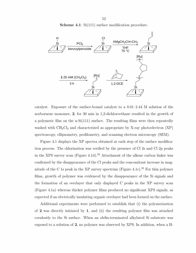
Scheme 4.1 depicts our methodology (i) an alkene linker of variable length is
coupled to a chlorinated Si surface using a Grignard reaction; (ii) an olefin cross-
metathesis reaction is used to obtain a surface-bound ruthenium ROMP catalyst,
and (iii) a monomer is added to effect growth of polymer onto the surface.
To implement this approach, a (111)-oriented crystalline n-type Si substrate 7 mm
x 7 mm in dimensions was first etched in 49% buffered HF(aq) for 30 s and then for
15 min in 40% NH4F(aq).29 The resulting H-terminated Si surface was then chlo-
rinated by exposure to saturated PCl5 in chlorobenzene for 45 min at 90–100 ◦C,
with a trace of benzoyl peroxide added to serve as a radical initiator.30, 31 This
chloride-capped Si surface32 was then exposed to allylmagnesium chloride for 14–
16 hr at 75 ◦C in tetrahydrofuran (THF).32 A ruthenium olefin metathesis catalyst
(Cy3P)2Cl2Ru=CHPh (Cy=cyclohexyl), (1),33, 34 was then reacted with the olefin-
modified Si surface by immersing the Si for 3 hr into a 25 mM solution of 1 in CH2Cl2.
The substrate was then rinsed several times with CH2Cl2 to remove any non-bound
catalyst. Exposure of the surface-bound catalyst to a 0.01–2.44 M solution of the
norbornene monomer, 2, for 30 min in 1,2-dichloroethane resulted in the growth of
a polymeric film on the n-Si(111) surface. The resulting films were then repeatedly
washed with CH2Cl2 and characterized as appropriate by X-ray photoelectron (XP)
spectroscopy, ellipsometry, profilometry, and scanning electron microscopy (SEM).
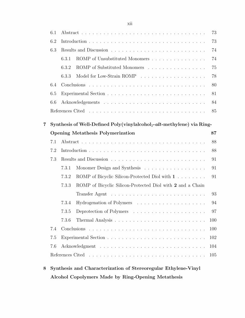
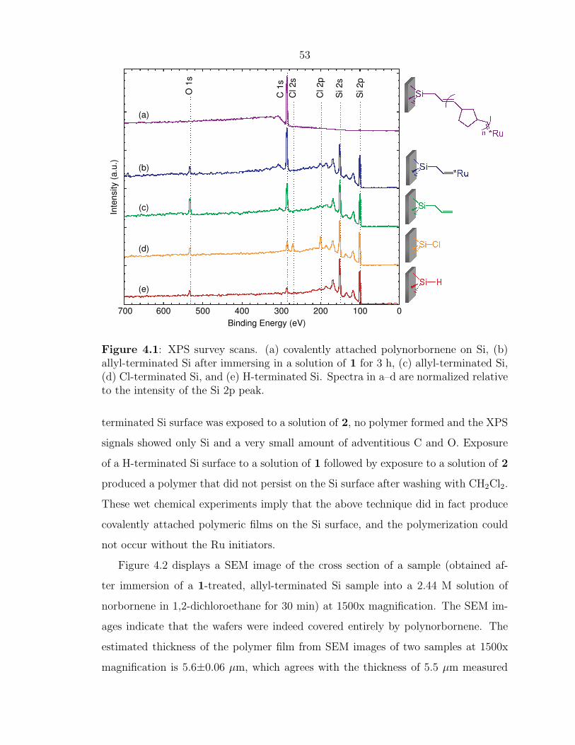
Figure 4.1 displays the XP spectra obtained at each step of the surface modifica-
tion process. The chlorination was verified by the presence of Cl 2s and Cl 2p peaks
in the XPS survey scan (Figure 4.1d).32 Attachment of the alkene carbon linker was
confirmed by the disappearance of the Cl peaks and the concomitant increase in mag-
nitude of the C 1s peak in the XP survey spectrum (Figure 4.1c).35 For thin polymer
films, growth of polymer was evidenced by the disappearance of the Si signals and
the formation of an overlayer that only displayed C peaks in the XP survey scan
(Figure 4.1a) whereas thicker polymer films produced no significant XPS signals, as
expected if an electrically insulating organic overlayer had been formed on the surface.
Additional experiments were performed to establish that (i) the polymerization
of 2 was directly initiated by 1, and (ii) the resulting polymer film was attached
covalently to the Si surface. When an olefin-terminated alkylated Si substrate was
exposed to a solution of 2, no polymer was observed by XPS. In addition, when a H-
53
700 600 500 400 300 200 100 0
Binding Energy (eV)
(a)
(b)
(c)
(d)
(e)
O 1
s
C 1
s
Cl 2s
Cl 2p
Si 2s
Si 2p
Inte
nsity (
a.u
.)
Figure 4.1: XPS survey scans. (a) covalently attached polynorbornene on Si, (b)allyl-terminated Si after immersing in a solution of 1 for 3 h, (c) allyl-terminated Si,(d) Cl-terminated Si, and (e) H-terminated Si. Spectra in a–d are normalized relativeto the intensity of the Si 2p peak.
terminated Si surface was exposed to a solution of 2, no polymer formed and the XPS
signals showed only Si and a very small amount of adventitious C and O. Exposure
of a H-terminated Si surface to a solution of 1 followed by exposure to a solution of 2
produced a polymer that did not persist on the Si surface after washing with CH2Cl2.
These wet chemical experiments imply that the above technique did in fact produce
covalently attached polymeric films on the Si surface, and the polymerization could
not occur without the Ru initiators.
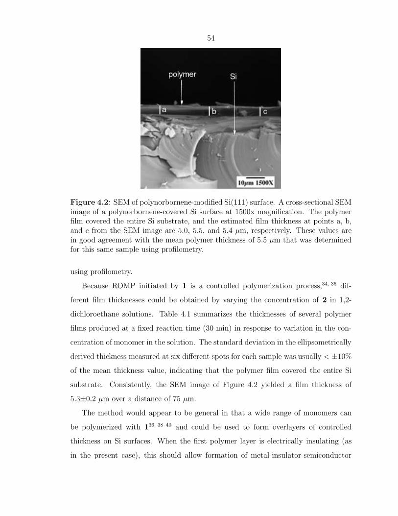
Figure 4.2 displays a SEM image of the cross section of a sample (obtained af-
ter immersion of a 1-treated, allyl-terminated Si sample into a 2.44 M solution of
norbornene in 1,2-dichloroethane for 30 min) at 1500x magnification. The SEM im-
ages indicate that the wafers were indeed covered entirely by polynorbornene. The
estimated thickness of the polymer film from SEM images of two samples at 1500x
magnification is 5.6±0.06 µm, which agrees with the thickness of 5.5 µm measured
54
Figure 4.2: SEM of polynorbornene-modified Si(111) surface. A cross-sectional SEMimage of a polynorbornene-covered Si surface at 1500x magnification. The polymerfilm covered the entire Si substrate, and the estimated film thickness at points a, b,and c from the SEM image are 5.0, 5.5, and 5.4 µm, respectively. These values arein good agreement with the mean polymer thickness of 5.5 µm that was determinedfor this same sample using profilometry.
using profilometry.
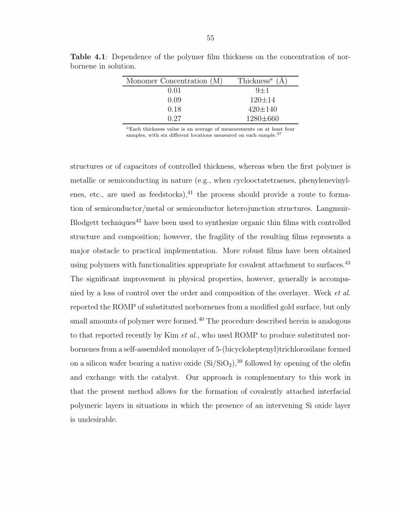
Because ROMP initiated by 1 is a controlled polymerization process,34, 36 dif-
ferent film thicknesses could be obtained by varying the concentration of 2 in 1,2-
dichloroethane solutions. Table 4.1 summarizes the thicknesses of several polymer
films produced at a fixed reaction time (30 min) in response to variation in the con-
centration of monomer in the solution. The standard deviation in the ellipsometrically
derived thickness measured at six different spots for each sample was usually < ±10%
of the mean thickness value, indicating that the polymer film covered the entire Si
substrate. Consistently, the SEM image of Figure 4.2 yielded a film thickness of
5.3±0.2 µm over a distance of 75 µm.
The method would appear to be general in that a wide range of monomers can
be polymerized with 136, 38–40 and could be used to form overlayers of controlled
thickness on Si surfaces. When the first polymer layer is electrically insulating (as
in the present case), this should allow formation of metal-insulator-semiconductor
55
Table 4.1: Dependence of the polymer film thickness on the concentration of nor-bornene in solution.
aEach thickness value is an average of measurements on at least foursamples, with six different locations measured on each sample.37
structures or of capacitors of controlled thickness, whereas when the first polymer is
metallic or semiconducting in nature (e.g., when cyclooctatetraenes, phenylenevinyl-
enes, etc., are used as feedstocks),41 the process should provide a route to forma-
tion of semiconductor/metal or semiconductor heterojunction structures. Langmuir-
Blodgett techniques42 have been used to synthesize organic thin films with controlled
structure and composition; however, the fragility of the resulting films represents a
major obstacle to practical implementation. More robust films have been obtained
using polymers with functionalities appropriate for covalent attachment to surfaces.43
The significant improvement in physical properties, however, generally is accompa-
nied by a loss of control over the order and composition of the overlayer. Weck et al.
reported the ROMP of substituted norbornenes from a modified gold surface, but only
small amounts of polymer were formed.40 The procedure described herein is analogous
to that reported recently by Kim et al., who used ROMP to produce substituted nor-
bornenes from a self-assembled monolayer of 5-(bicycloheptenyl)trichlorosilane formed
on a silicon wafer bearing a native oxide (Si/SiO2),39 followed by opening of the olefin
and exchange with the catalyst. Our approach is complementary to this work in
that the present method allows for the formation of covalently attached interfacial
polymeric layers in situations in which the presence of an intervening Si oxide layer
is undesirable.
56
4.4 Conclusions
In conclusion, we have demonstrated the growth of polymer films that are cova-
lently attached to Si surfaces via a Si-C linkage. The thickness of the linker unit
can be controlled at the molecular level, and the thickness of the polymer can be
independently controlled by varying the concentration of monomer, so that polymer
thicknesses between 0.9 and 5500 nm can be obtained.
57
References Cited
[1] Bansal, A.; Lewis, N. S. J. Phys. Chem. B 1998, 102, 4058.[2] Sailor, M. J.; Klavetter, F. L.; Grubbs, R. H.; Lewis, N. S. Nature 1990, 346,
155.[3] Huck, W. T. S.; Yan, L.; Stroock, A.; Haag, R.; Whitesides, G. M. Langmuir
1999, 15, 6862.[4] Clark, S. L.; Montague, M.; Hammond, P. T. Supramol. Sci. 1997, 4, 141.[5] Whidden, T. K.; Ferry, D. K.; Kozicki, M. N.; Kim, E.; Kumar, A.; Wilbur, J.;
Whitesides, G. M. Nanotechnology 1996, 7, 447.[6] Sailor, M. J.; Ginsburg, E. J.; Gorman, C. B.; Kumar, A.; Grubbs, R. H.;
Lewis, N. S. Science 1990, 249, 1146.[7] Bansal, A.; Lewis, N. S. J. Phys. Chem. B 1998, 102, 1067.[8] Royea, W. J.; Juang, A.; Lewis, N. S. Appl. Phys. Lett. 2000, 77, 1988.[9] Sze, S. The Physics of Semiconductor Devices; Wiley: New York, 2nd ed.; 1981.
[10] Royea, W. J.; Michalak, D. J.; Lewis, N. S. Appl. Phys. Lett. 2000, 77, 2566.[11] Eades, W. D.; Swanson, R. M. J. Appl. Phys. 1985, 58, 4267.[12] Yablonovitch, E.; Gmitter, T. J. Sol. St. Electron. 1992, 35, 261.[13] Aberle, A. G.; Glunz, S.; Warta, W. J. Appl. Phys. 1992, 71, 4422.[14] Boukherroub, R.; Morin, S.; Bensebaa, F.; Wayner, D. D. M. Langmuir 1999,
15, 3831.[15] Sieval, A. B.; Vleeming, V.; Zuilhof, H.; Sudholter, E. J. R. Langmuir 1999,
15, 8288.[16] Boukherroub, R.; Wayner, D. D. M. J. Am. Chem. Soc. 1999, 121, 11513.[17] Sieval, A. B.; Demirel, A. L.; Nissink, J. W. M.; Linford, M. R.; van der
Mass, J. H.; de Jeu, W. H.; Zuilhof, H.; Sudholter, E. J. R. Langmuir 1998,14, 1759.
[18] Linford, M. R.; Chidsey, C. E. D. J. Am. Chem. Soc. 1993, 115, 12631.[19] Linford, M. R.; Fenter, P.; Eisenberger, P. M.; Chidsey, C. E. D. J. Am. Chem.
Soc. 1995, 117, 3145.[20] Zazzera, L. A.; Evans, J. F.; Deruelle, M.; Tirrell, M.; Kessel, C. R.; McKe-
own, P. J. Electrochem. Soc. 1997, 144, 2184.[21] Feng, W. J.; Miller, B. Langmuir 1999, 15, 3152.[22] Effenberger, F.; Gotz, G.; Bidlingmaier, B.; Wezstein, M. Angew. Chem., Int.
Ed. 1998, 37, 2462.[23] Allongue, P.; de Villeneuve, C. H.; Pinson, J.; Ozanam, F.; Chazalviel, J. N.;
Wallart, X. Electochim. Acta 1998, 43, 2791.
58
[24] He, J.; Patitsas, S. N.; Preston, K. F.; Wolkow, R. A.; Wayner, D. D. M.Chem. Phys. Lett. 1998, 286, 508.
[25] de Villeneuve, C. H.; Pinson, J.; Bernard, M. C.; Allongue, P. J. Phys. Chem.B 1997, 101, 2415.
[26] Wagner, P.; Nock, S.; Spudich, J. A.; Volkmuth, W. D.; Chu, S.; Cicero, R. L.;Wade, C. P.; Linford, M. R.; Chidsey, C. E. D. J. Struct. Biol. 1997, 119, 189.
[27] Hamers, R. J.; Coulter, S. K.; Ellison, M. D.; Hovis, J. S.; Padowitz, D. F.;Schwartz, M. P.; Greenlief, C. M.; Russell, J. Accts. Chem. Res. 2000, 33, 617.
[28] Schwartz, M. P.; Ellison, M. D.; Coulter, S. K.; Hovis, J. S.; Hamers, R. J. J.Am. Chem. Soc. 2000, 122, 8529.
[29] Higashi, G. S.; Becker, R. S.; Chabal, Y. J.; Becker, A. J. Appl. Phys. Lett.1991, 58, 1656.
[30] Hassler, K.; Koll, W. J. Organomet. Chem. 1995, 487, 223.[31] Wyman, D. P.; Wang, J. Y. C.; Freeman, W. R. J. Org. Chem. 1963, 28, 3173.[32] Bansal, A.; Li, X.; Lauermann, I.; Lewis, N. S.; Yi, S. I.; Weinberg, W. H. J.
Am. Chem. Soc. 1996, 118, 7225.[33] Schwab, P.; France, M. B.; Ziller, J. W.; Grubbs, R. H. Angew. Chem., Int.
Ed. 1995, 34, 2039.[34] Schwab, P.; Grubbs, R. H.; Ziller, J. W. J. Am. Chem. Soc. 1996, 118, 100.[35] No Ru signal was observed in the XPS data, however, the intensity of this signal
is expected to be very low. Assuming that reagent 1 has bound onto 50% of thetotal available groups in a monolayer of olefin on the Si surface implies a 1:41Ru/C ratio for the atoms in the overlayer. With the atomic sensitivity factors ofRu 3d5/2 and C 1s being 1.55 and 0.205, respectively,44 the area of the Ru 3d5/2
peak is calculated to be 18% of the C 1s signal. Because both the Ru 3d5/2 andRu 3d3/2 peak positions are within 5 eV of the C 1s peak, observation of suchsmall Ru peaks in the presence of these C 1s signals is not readily possible withour XPS instrument (VG Instruments M-probe Spectrometer, with a full widthat half maximum of 1.50±0.01 eV for the Au 4f7/2 peak in survey scan mode).Additionally, the Ru 3p3/2 peak is about 1/3 as intense as the Ru 3d5/2 peak, sothe estimated relative peak area of the Ru 3p3/2 would be only 6% of the C 1speak area.
[36] Amir-Ebrahimi, V.; Corry, D. A.; Hamilton, J. G.; Thompson, J. M.;Rooney, J. J. Macromolecules 2000, 33, 717.
[37] The standard deviation between measurements at six separate locations on eachsample was usually less than ±10% of the mean film thickness value on thatsample; thus, the quoted standard deviation in film thickness for the thickerfilms predominantly reflects the differences in polymer film thickness betweenthe different experimental trials.
[38] Maughon, B. R.; Morita, T.; Bielawski, C. W.; Grubbs, R. H. Macromolecules2000, 33, 1929.
[39] Kim, N. Y.; Jeon, N. L.; Choi, I. S.; Takami, S.; Harada, Y.; Finnie, K. R.;Girolami, G. S.; Nuzzo, R. G.; Whitesides, G. M.; Laibinis, P. E. Macro-molecules 2000, 33, 2793.
59
[40] Weck, M.; Jackiw, J. J.; Rossi, R. R.; Weiss, P. S.; Grubbs, R. H. J. Am.Chem. Soc. 1999, 121, 4088.
[41] Scherman, O. A.; Grubbs, R. H. Synth. Met. 2001, 124, 431–434.[42] Ulman, A. An Introduction to Ultrathin Organic Films; Academic Press: Boston,
1991.[43] Lenk, T. J.; Hallmark, V. M.; Rabolt, J. F.; Haussling, L.; Ringsdorf, H.
Macromolecules 1993, 26, 1230.[44] Wagner, C. D.; Riggs, W. M.; Davis, L. E.; Moulder, J. F.; Muilenberg, G. E.
Handbook of X-Ray Photoelectron Spectroscopy; Perkin-Elmer Corporation Phys-ical Electronics Division: Eden Prairie, Minnesota, 1979.
60
Chapter 5
Synthesis of Polymer DielectricLayers for Organic Thin-FilmTransistors via Surface-InitiatedRing-Opening MetathesisPolymerization
61
5.1 Abstract
Polymer-based dielectric layers for use in electronic devices such as thin-film tran-
sistors (TFTs), capacitors, and other logic elements have attracted much attention
for their low cost, processability, and tunable properties. Current methods for incor-
porating organic materials into these devices are either not ideal or not possible when
applied to the deposition of polymer dielectric materials. The living ring-opening
metathesis polymerization (ROMP) of strained, cyclic olefins can provide a method
for growing organic polymers from a surface. ROMP would allow for pinhole-free di-
electrics with controlled layer thickness and tunable electronic and surface properties
by growing a covalently attached polymer from the surface. Furthermore, ROMP
from surfaces is unique in its ability to polymerize monomers from either solution or
vapor phase and can be performed under mild ambient conditions, afford polymer
growth in minutes, and allow for flexibility in polymer structure and dielectric layer
composition. We have shown the feasibility of producing TFTs and capacitors using
surface attached ROMP polymers as a layer of dielectric material. Preliminary re-
sults indicate that this method will allow for highly tunable materials with desired
properties. The ability to grow conformal polymer layers on any topology will be
very important as device dimensions and applications change.
5.2 Introduction
The use of organic materials in electronic devices such as field effect transistors
(FETs) and light emitting diodes (LEDs) has become an attractive approach toward
decreasing weight and cost, simplifying production, and increasing versatility of these
devices. Electronic devices containing polymer layers have been incorporated into
applications such as active-matrix displays1–3 and integrated circuits.4, 5
For optimal FET performance, a polymer dielectric layer should be chemically
and electrically compatible, with the organic semiconductor facilitating a smooth
interface between adjacent layers.6 Low leakage and tunable dielectric properties are
62
also desirable. This requires that the layer be pinhole-free, with controlled thickness
and composition.
Current methods for depositing polymer layers include spin-coating, ink-jet print-
ing, and screen printing.7–9 Unlike these methods, surface-initiated polymerizations
can produce densely packed, conformal layers over any surface topology. Compared
with other surface-initiated polymerization methods, ring-opening metathesis poly-
merization (ROMP) allows mild conditions and short reaction times. Therefore, we
have chosen to investigate surface-initiated ROMP (SI-ROMP) as a method for form-
ing polymer dielectric layers.
SI-ROMP has been demonstrated from Au, Si, and Si/SiO2 surfaces using cata-
lyst 1 and a variety of linking molecules.10–12 Conformal block copolymers grown on
Au nanoparticles demonstrated the living nature of SI-ROMP with catalyst 1.13 We
report here that SI-ROMP polymer layers can be used as the dielectric layer in elec-
tronic devices, either alone or in tandem with an inorganic dielectric layer. We also
report that, as with solution-phase ROMP,14 catalyst 2 is more active than catalyst
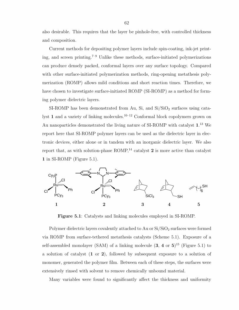
1 in SI-ROMP (Figure 5.1).
Cl
Ru
PCy3
Cl
NN
PhCl
Ru
PCy3
Cl
Ph
Cy3P
SiCl3 SH
SH6
1 2 3 4 5
Figure 5.1: Catalysts and linking molecules employed in SI-ROMP.
Polymer dielectric layers covalently attached to Au or Si/SiO2 surfaces were formed
via ROMP from surface-tethered metathesis catalysts (Scheme 5.1). Exposure of a
self-assembled monolayer (SAM) of a linking molecule (3, 4 or 5)15 (Figure 5.1) to
a solution of catalyst (1 or 2), followed by subsequent exposure to a solution of
monomer, generated the polymer film. Between each of these steps, the surfaces were
extensively rinsed with solvent to remove chemically unbound material.
Many variables were found to significantly affect the thickness and uniformity
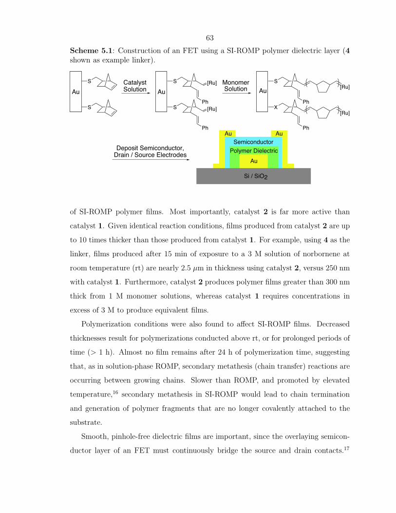
63
Scheme 5.1: Construction of an FET using a SI-ROMP polymer dielectric layer (4shown as example linker).
S[Ru]
X[Ru]
MonomerSolution
S [Ru]
S [Ru]
CatalystSolution AuAu Au
S
S
Deposit Semiconductor,Drain / Source Electrodes
Ph
Ph
Ph
Ph
SemiconductorPolymer Dielectric
Au
Si / SiO2
AuAu
of SI-ROMP polymer films. Most importantly, catalyst 2 is far more active than
catalyst 1. Given identical reaction conditions, films produced from catalyst 2 are up
to 10 times thicker than those produced from catalyst 1. For example, using 4 as the
linker, films produced after 15 min of exposure to a 3 M solution of norbornene at
room temperature (rt) are nearly 2.5 µm in thickness using catalyst 2, versus 250 nm
with catalyst 1. Furthermore, catalyst 2 produces polymer films greater than 300 nm
thick from 1 M monomer solutions, whereas catalyst 1 requires concentrations in
excess of 3 M to produce equivalent films.
Polymerization conditions were also found to affect SI-ROMP films. Decreased
thicknesses result for polymerizations conducted above rt, or for prolonged periods of
time (> 1 h). Almost no film remains after 24 h of polymerization time, suggesting
that, as in solution-phase ROMP, secondary metathesis (chain transfer) reactions are
occurring between growing chains. Slower than ROMP, and promoted by elevated
temperature,16 secondary metathesis in SI-ROMP would lead to chain termination
and generation of polymer fragments that are no longer covalently attached to the
substrate.
Smooth, pinhole-free dielectric films are important, since the overlaying semicon-
ductor layer of an FET must continuously bridge the source and drain contacts.17
64
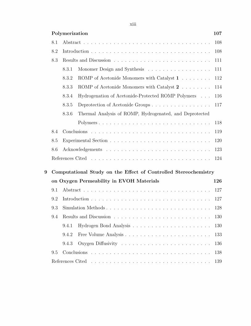
Vds(V)-20 -40 -60 -80 -1000
-20
0
-5
-10
-15
-25
I ds(
µA
)
Vg=-100 V
Vg=40 V
Vg(V)-40 400-80
I ds(
µA
)
-20
-15
-10
-5
0
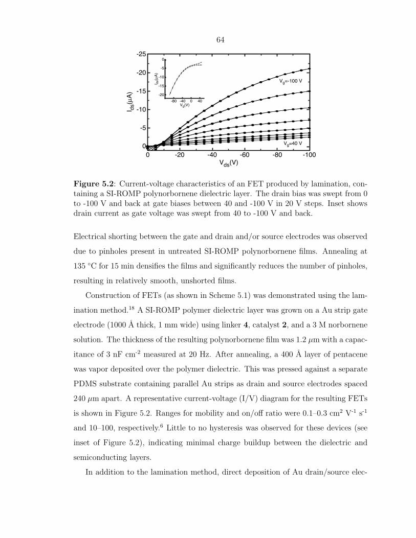
Figure 5.2: Current-voltage characteristics of an FET produced by lamination, con-taining a SI-ROMP polynorbornene dielectric layer. The drain bias was swept from 0to -100 V and back at gate biases between 40 and -100 V in 20 V steps. Inset showsdrain current as gate voltage was swept from 40 to -100 V and back.
Electrical shorting between the gate and drain and/or source electrodes was observed
due to pinholes present in untreated SI-ROMP polynorbornene films. Annealing at
135 ◦C for 15 min densifies the films and significantly reduces the number of pinholes,
resulting in relatively smooth, unshorted films.
Construction of FETs (as shown in Scheme 5.1) was demonstrated using the lam-
ination method.18 A SI-ROMP polymer dielectric layer was grown on a Au strip gate
electrode (1000 A thick, 1 mm wide) using linker 4, catalyst 2, and a 3 M norbornene
solution. The thickness of the resulting polynorbornene film was 1.2 µm with a capac-
itance of 3 nF cm-2 measured at 20 Hz. After annealing, a 400 A layer of pentacene
was vapor deposited over the polymer dielectric. This was pressed against a separate
PDMS substrate containing parallel Au strips as drain and source electrodes spaced
240 µm apart. A representative current-voltage (I/V) diagram for the resulting FETs
is shown in Figure 5.2. Ranges for mobility and on/off ratio were 0.1–0.3 cm2 V-1 s-1
and 10–100, respectively.6 Little to no hysteresis was observed for these devices (see
inset of Figure 5.2), indicating minimal charge buildup between the dielectric and
semiconducting layers.
In addition to the lamination method, direct deposition of Au drain/source elec-
65
Vds(V)
I ds(
µA
)
-100 -60-50-40-30-20
-1.2
-1.0
-0.2
-0.4
-0.6
-0.8
0
Vg=-60 V
Vg=0 V
10 102
106
105
104
103
Frequency (Hz)
Cap
acita
nce
(nF
/cm
2 )
3
4
2
5
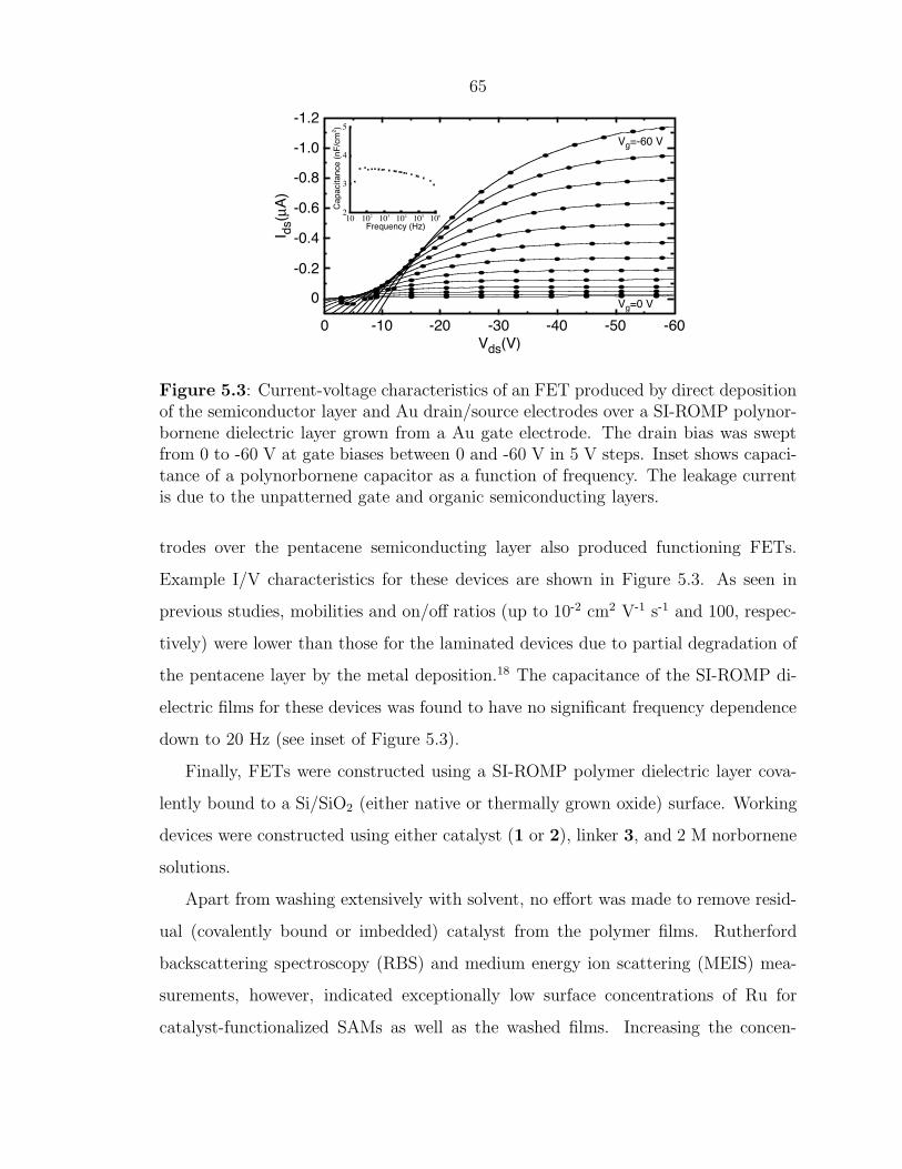
Figure 5.3: Current-voltage characteristics of an FET produced by direct depositionof the semiconductor layer and Au drain/source electrodes over a SI-ROMP polynor-bornene dielectric layer grown from a Au gate electrode. The drain bias was sweptfrom 0 to -60 V at gate biases between 0 and -60 V in 5 V steps. Inset shows capaci-tance of a polynorbornene capacitor as a function of frequency. The leakage currentis due to the unpatterned gate and organic semiconducting layers.
trodes over the pentacene semiconducting layer also produced functioning FETs.
Example I/V characteristics for these devices are shown in Figure 5.3. As seen in
previous studies, mobilities and on/off ratios (up to 10-2 cm2 V-1 s-1 and 100, respec-
tively) were lower than those for the laminated devices due to partial degradation of
the pentacene layer by the metal deposition.18 The capacitance of the SI-ROMP di-
electric films for these devices was found to have no significant frequency dependence
down to 20 Hz (see inset of Figure 5.3).
Finally, FETs were constructed using a SI-ROMP polymer dielectric layer cova-
lently bound to a Si/SiO2 (either native or thermally grown oxide) surface. Working
devices were constructed using either catalyst (1 or 2), linker 3, and 2 M norbornene
solutions.
Apart from washing extensively with solvent, no effort was made to remove resid-
ual (covalently bound or imbedded) catalyst from the polymer films. Rutherford
backscattering spectroscopy (RBS) and medium energy ion scattering (MEIS) mea-
surements, however, indicated exceptionally low surface concentrations of Ru for
catalyst-functionalized SAMs as well as the washed films. Increasing the concen-
66
tration of ruthenium bonded to the SAM may result in denser films and less leakage.
These devices demonstrate that surface-initiated polymer dielectric layers are both
chemically and electrically compatible with other FET component layers. In general,
a high yield (> 90%) of working TFTs was obtained only with annealed dielectric
films at least 1 µm thick. Further optimization of polymer growth conditions, yielding
higher graft densities and reduced surface roughness, should allow the use of thinner
films as well as improve the compatibility between the polymer film and organic
semiconductor.19
For devices using patterned (e.g., striped Au) substrates, the SI-ROMP polymer
grows conformally over the gate electrode, eliminating the need to pattern the di-
electric. Furthermore, spin-coated dielectric layers tend to be thinner at the edges
of the electrode, leading to a lower breakdown voltage. In contrast, the thickness of
the surface-grown polymer layer can be about the same at the edges as for the flat
surface, illustrating a clear advantage of SI-ROMP.
In conclusion, construction of FETs using SI-ROMP polymer dielectric layers
has been demonstrated. Mild reaction conditions, short reaction times, and simple
solution processing methods make SI-ROMP an attractive method for constructing
polymer dielectric layers. Layer thicknesses ranging from below 100 nm to above 2 µm
are accessible simply by varying the polymerization conditions. Research is underway
in optimizing FET device characteristics, as well as incorporating SI-ROMP block
furan (anhydrous), hexamethyldisilathiane, tetrabutylammoniumfluoride (1.0 M in
THF with 5% H2O), and bicyclo[2.2.1]hept-2-ene (norbornene) were used as re-
ceived from Aldrich. Dichloromethane (Aldrich, anhydrous) was degassed prior to
use by sparging with argon. 1,2-dichloroethane (Aldrich, anhydrous) was first filtered
through a plug of neutral alumina (Brockman Grade I; this procedure is necessary in
67
order to have film growth), and then degassed by sparging with argon. 5-(Bicyclo-
heptenyl)trichlorosilane (3) was purchased from Gelest, Inc., and used as received.
Bicyclo[2.2.1]hept-5-ene-2-methanethiol (4) was prepared as described in the litera-
ture.20 Catalysts 121 and 222were prepared as described in the literature. 7-Octene-1-
thiol (5) was prepared according to a literature procedure,23 with 8-bromo-1-octene
as starting material.
Substrate Preparation and Metal/Organic Semiconductor Deposition.
Silicon wafers containing a 3000 A thermally grown oxide layer were obtained from
Silicon Quest International. Gold substrates (typically composed of a 500 or 1000 A
layer of gold over a 50 or 100 A layer of titanium, both vacuum deposited in an e-beam
evaporator) were prepared on silicon wafers containing a native oxide layer (Silicon
Quest International). Substrates were cut into 1 cm2 squares, individually cleaned
by sequential washings with acetone, deionized water, and iPrOH, and dried in a
stream of dry nitrogen (N2). The substrates were then soaked in a boiling solution
of H2O/H2O2/NH4OH (5:1:1) for 30 min, washed with water and iPrOH, and dried
with dry N2.
Surface Functionalization. In a typical procedure using gold substrates, self-
assembled monolayers (SAMs) were formed by submerging freshly cleaned substrate
squares in a filtered solution of thiol in absolute EtOH (typically 0.5 or 0.75 mM) for
24 h. The squares were then removed and washed, first with EtOH, then with iPrOH
before being dried in a stream of dry N2. Using Si/SiO2 substrates, freshly cleaned
squares were submerged for 6 h in a 0.5 wt% solution of trichlorosilane in pentane in
a N2 glovebox. The squares were then removed, sonicated for 5 min each in toluene
(2 times), 50/50 toluene/acetone, and acetone, and dried in a stream of dry N2.
Reaction of the olefin-functionalized substrates with catalyst was done in dichloro-
methane solutions of catalyst 1 or 2 (typically 13 or 25 mM) at room temperature
(rt) or 40 ◦C. After the prescribed length of time, the squares were removed from solu-
tion, washed thoroughly with dichloromethane, and dried under N2. They were then
immediately placed in a fresh, filtered solution of norbornene in 1,2-dichloroethane
and allowed to react for a prescribed length of time at rt or 40 ◦C. The squares were
68
then washed thoroughly with dichloromethane and dried under vacuum.
Device Construction. For the FETs using a gold strip as the gate electrode
deposited on SiO2 (both lamination and direct deposition methods), linker 4 and
catalyst 2 were used. Catalyst attachment and norbornene polymerization were done
at rt for 10 min and 15 min, respectively. The thickness of the polynorbornene film
was 1.2 µm for the lamination devices, and ranged from 800 to 1100 nm for the direct
deposition samples. In mobility calculations, a width (W) of 2–3 mm and length
(L) of 1 mm were used for the laminated devices. A width of 940 µm and length of
240 µm were used for the direct deposition devices.
For the FETs using Si/SiO2 as gate electrode, catalyst attachment was done with
dichloromethane solutions of catalyst 1 or 2 at rt for 10 min, and the polymerizations
were carried out with 1,2-dichloroethane solutions of norbornene (between 2 and 4 M)
at rt, times varying between 15 and 40 min. The thickness of the polynorbornene
films, which were very smooth and did not require annealing, ranged between 230
and 800 nm, but only those films thicker than 600 nm were used to make TFTs.
The organic semiconducting layer of pentacene (Aldrich) was deposited by thermal
evaporation under vacuum (typically to a thickness of 300 A). Gold overlayers were
deposited in an e-beam evaporator under vacuum.
Characterization. Ellipsometric measurements were performed on a Rudolph
Ellipsometer AutoEL. Profilometric measurements were measured using a Dektak
3030. Current-voltage characteristics were obtained with a Hewlett-Packard (HP)
4155A semiconductor parameter analyzer. AFM Tapping Mode data was acquired
on a JEOL JSPM-4210 scanning probe microscope in a nitrogen environment. “NON-
CONTACT ULTRASHAR” silicon cantilevers were purchased from NT-MDT, Ltd.
Rutherford backscattering spectroscopy (RBS) and medium energy ion scattering
(MEIS, a low energy ultrahigh resolution variant of RBS) were performed at the Rut-
gers University ion scattering facility. 1.5 MeV He ions (in RBS) and 100 keV protons
(in MEIS) were used to quantify film composition and thickness.
69
5.4 Acknowledgements
The authors thank the National Science Foundation, Office of Naval Research,
NJCOOE, and Lucent Technologies for financial support, and Dr. Brian Connell and
Daniel P. Sanders for advice on this manuscript.
70
References Cited
[1] Rogers, J. A.; Bao, Z. J. Polym. Sci. Part A: Polym. Chem. 2002, 40, 3327–3334.
[2] Sheraw, C. D.; Zhou, L.; Huang, J. R.; Gundlach, D. J.; Jackson, T. N.;Kane, M. G.; Hill, I. G.; Hammond, M. S.; Campi, J.; Greening, B. K.;Francl, J.; West, J. Appl. Phys. Lett. 2002, 80, 1088–1090.
[3] Huitema, H. E. A.; Gelinck, G. H.; van der Putten, J. B. P. H.; Kuijk, K.;Hart, C. M.; Cantatore, E.; Herwig, P. T.; van Breemen, A. J. J. M.;de Leeuw, D. M. Nature 2001, 414, 599.
[4] Gelinck, G. H.; Geuns, T. C. T.; de Leeuw, D. M. Appl. Phys. Lett. 2000, 77,1487–1489.
[5] Crone, B. K.; Dodabalapur, A.; Sarpeshkar, R.; Filas, R. W.; Lin, Y. Y.;Bao, Z.; O’Neill, J. H.; Li, W.; Katz, H. E. J. Appl. Phys. 2001, 89, 5125–5132.
[6] Performance as measured by mobility and on/off ratio. See Katz, H. E.; Bao, Z.J. Phys. Chem. B 2000, 104, 671–678.
[8] Bao, Z. N.; Feng, Y.; Dodabalapur, A.; Raju, V. R.; Lovinger, A. J. Chem.Mat. 1997, 9, 1299–1301.
[9] Kawase, T.; Sirringhaus, H.; Friend, R. H.; Shimoda, T. Adv. Mater. 2001,13, 1601–1604.
[10] Weck, M.; Jackiw, J. J.; Rossi, R. R.; Weiss, P. S.; Grubbs, R. H. J. Am.Chem. Soc. 1999, 121, 4088–4089.
[11] Juang, A.; Scherman, O. A.; Grubbs, R. H.; Lewis, N. S. Langmuir 2001, 17,1321–1323.
[12] Kim, N. Y.; Jeon, N. L.; Choi, I. S.; Takami, S.; Harada, Y.; Finnie, K. R.;Girolami, G. S.; Nuzzo, R. G.; Whitesides, G. M.; Laibinis, P. E. Macro-molecules 2000, 33, 2793–2795.
[13] Watson, K. J.; Zhu, J.; Nguyen, S. T.; Mirkin, C. A. J. Am. Chem. Soc. 1999,121, 462–463.
[14] Bielawski, C. W.; Grubbs, R. H. Angew. Chem., Int. Ed. 2000, 39, 2903–2906.[15] In general, films produced with linker 4 were thicker than those produced with
linker 5. Catalyst attachment is likely more efficient with 4; the reasons for thisare currently under investigation.
[16] Choi, T. L.; Grubbs, R. H. Angew. Chem., Int. Ed. 2003, 42, 1743–1746.
71
[17] Bao, Z. N.; Rogers, J. A.; Katz, H. E. J. Mater. Chem. 1999, 9, 1895–1904.[18] Loo, Y. L.; Someya, T.; Baldwin, K. W.; Bao, Z.; Ho, P.; Dodabalapur, A.;
Katz, H. E.; Rogers, J. A. Proc. Natl. Acad. Sci. USA 2002, 99, 10252–10256.[19] Increased grain-size was observed when pentacene was deposited over SI-ROMP
polymer layers that had been annealed.[20] Inokuma, S.; Sugie, A.; Moriguchi, K.; Shimomura, H.; Katsube, J. Heterocy-
cles 1982, 19, 1909–1913.[21] Schwab, P.; Grubbs, R. H.; Ziller, J. W. J. Am. Chem. Soc. 1996, 118, 100–110.[22] Sanford, M. S.; Ulman, M.; Grubbs, R. H. J. Am. Chem. Soc. 2001, 123,
749–750.[23] Hu, J.; Fox, M. A. J. Org. Chem. 1999, 64, 4959–4961.
72
Chapter 6
Ring-Opening MetathesisPolymerization ofFunctionalized-Low-StrainMonomers with Ruthenium-BasedCatalysts
73
6.1 Abstract
A detailed study of the ring-opening metathesis polymerization of low-strain
monomers with ruthenium catalysts is reported. The effects of monomer concentra-
tion, reaction temperature, and catalyst dependence are described for unsubstituted
cycloolefins. The ROMP of low-strain olefins with polar substituents is also exam-
ined with ruthenium olefin metathesis catalysts and a predictive model for ROMP
feasibility is proposed.
6.2 Introduction
Functionalized linear polymers represent an important class of materials. Several
methods have been established to prepare functionalized polymers such as ionic and
free radical polymerization of vinyl monomers, group transfer polymerization (GTP),
and, more recently, ring-opening metathesis polymerization (ROMP).1–3 ROMP is an
attractive method to synthesize functional polymers as it is robust, produces abso-
lutely linear material, and is amenable to forming various copolymers of controlled
architecture.4, 5 Substituted cyclobutenes and cyclooctenes have been used extensively
to prepare linear polymers with a wide range of functionality.6, 7 With these monomers
it is difficult (or in the case of mono-substitution, impossible) to control the regioreg-
ularity of functionalities along the polymer backbone. Symmetrically substituted 5-
and 7-membered ring monomers provide access to a range of regioregular polymers.
Few examples, however, are reported in the literature.8–11 The low ring strains inher-
ent to 5-, 6-, and 7-membered cycloalkenes12 make them more challenging substrates
for ROMP.
The driving force behind the ROMP of cyclic olefins is the release of strain en-
ergy,2 encompassed by the enthalpic term, ∆H, in the equation below.
∆G = ∆H – T∆S
Monomer concentration and reaction temperature are intimately associated with
thermodynamics of ROMP. For every cyclic olefin monomer, there exists a critical
74
monomer concentration below which no polymerization will occur at a given tem-
perature. Performing the ROMP at low temperatures can mitigate the entropic loss
inherent to all polymerizations and drive the reaction to high molecular weight poly-
mer. Lower reaction temperatures, however, require catalysts with higher activities.
As a result, ROMP of low-strain monomers has traditionally been performed with
highly active early transition metal catalysts.2, 9 Unfortunately, these catalysts are
not tolerant of many polar functionalities. It is well established that ruthenium-
based olefin metathesis catalysts, such as 1, demonstrate significantly more tolerance
towards polar functionality.13, 14 It was recently demonstrated that catalyst 2 was
capable of performing the ROMP of cyclopentene at 25 ◦C.15 We now report that
ruthenium catalysts 1, 2, and 3 (Figure 6.1) are all capable of polymerizing low-
strain cycloolefins, so that the ROMP of 5- and 7-membered cycloalkenes with polar
aROMP of neat monomer. bPolymerizations carried out in in CH2Cl2. cPolymerization time of 24 h.dPolymerization time of 30 min. eSamples run in THF; molecular weight values obtained using MALLS. f Lowyields due to sparing solubility of 3 in neat monomers.
with early transition metal catalysts, but present no difficulty for the ruthenium sys-
tems.5, 14, 15 This would allow for the direct preparation of polar functionalized linear
polymers without the need for subsequent polymer modification.4, 13 Furthermore,
as we have previously demonstrated, ROMP of a symmetric monomer will ensure
an absolutely regioregular polymer,13, 16 thus providing new materials for detailed
structure–property studies.
The addition of substituents to monomers 4 and 5 will certainly make the ROMP
of these low-strain monomers more challenging.2 This can be explained by the “gem-
77
dialkyl effect” whereby substituents on a ring serve to stabilize the ring-closed system
relative to its linear counterpart.17 As ROMP is a process governed by thermodynamic
equilibrium, this effect results in a lower concentration of the linear polymer.
The polar monomers employed in this study, and shown in Scheme 6.2, possess
ester, silyl ether, and ketone functionalities. The ROMP of monomers 6, 7, 8, 9 pro-
vide a synthetic route for oxygen containing materials such as ethylene vinyl alcohol
(EVOH) and ethylene carbon monoxide (E/CO) copolymers. These materials have
been demonstrated to have useful properties in commercial applications.13, 18, 19
Scheme 6.2: ROMP of substituted low-strain monomers.
RR
n
n
[Ru]
[Ru]
R'
R'
R = OAcR = OTBSR = O
R' = O
n
[Ru]OAc
OAc
n
[Ru]OAc
OAc
AcO
OAc
X
X
6,7,8,
9,
10
11
ROMP of the substituted monomers was successfully carried out neat at 25 ◦C
with catalysts 1–3, as illustrated in Table 6.2. Entries 1–6 in Table 6.2 illustrate
that the ROMP of symmetric monomers 6 and 7 could be carried out in high yield
and with controlled molecular weights with all three ruthenium catalysts. More-
over, no significant difference was observed in the ROMP of 6 and 7 as expected for
structurally similar monomers. Monomer 8 does not undergo polymerization with
catalysts 1 or 2, indicating a low ring strain. Catalyst 3, however, allows for the
formation of poly(8) which is an insoluble material. This suggests that poly(8) is
78
trapped through a kinetic process.1, 20, 21 Catalyst 3 is known to initiate much faster
than either 1 or 2, and may allow for rapid polymerization of 8 to high molecular
weight insoluble polymer. No conditions were found under which monomers 10 and
11 would successfully polymerize.
Table 6.2: Results for the ROMP of 6–11 with ruthenium catalysts at 25 ◦C.
aROMP of neat monomer. bPolymerizations carried out in in CH2Cl2. cPolymerization time of24 h. dPolymerization time of 30 min. eSamples run in THF; molecular weight values obtained usingMALLS. f Low yields due to sparing solubility of 3 in neat monomers.
6.3.3 Model for Low-Strain ROMP
By varying the placement and nature of the substituents, we observed a marked
effect on a monomer’s potential to undergo ROMP. A method to predict whether or
not ROMP of a particular monomer is feasible would be very helpful for the design
of new functionalized monomers. The ease of ROMP is reflected by the strain energy
of each monomer.2, 13 Therefore, a model to predict strain energy should correlate to
ROMP feasibility as well.
We chose to model the strain energy of a cyclic olefin with the enthalpic terms
79
n
+n
∆Hs
Figure 6.2: Isodesmic reaction used to calculate the strain energy released by ROMP.
of a ring-closing metathesis reaction (Figure 6.2). Our model reaction is isodesmic,
having the same number and type of bonds in both reactants and products,22 so that
the change in energy is solely due to the strain inherent in the cycle form. The ring
strain for the cyclic olefin is the difference in energy between the products and the
reactant.
In order to validate our model, un-substituted, cyclic olefins ranging from cyclo-
propene to cyclooctene were calculated and compared with their experimentally de-
termined strain energies. The calculations were carried out using DFT with a B3LYP
functional and a 6-31G∗∗ basis set. As can be seen by the graph in Figure 6.3, the cor-
relation of calculated values with experiment is quite good. Slightly larger deviations
are observed for cycloheptene and cyclooctene as a result of a natural distribution of
several conformers at 298 K for these larger rings that are not reflected in our cal-
culations. We also carried out these calculations at a semi-empirical level of theory
with AM1, PM3 and PM5 parameterization schemes; however, all of these resulted
in poor agreement with experimental results.
Satisfied with our method, we proceeded to calculate the strain energies for the
substituted monomers described above. The calculated values are shown in Table 6.3.
Again, the experimental results we observe in this study appear to correlate with our
model. Under our polymerization conditions, it appears that the minimal strain en-
ergy necessary for successful ROMP lies between 3.4 and 4.4 kcal/mol. The successful
development of this model should allow for the evaluation of a new monomer’s ability
to undergo ROMP.
80
0
10
20
30
40
50
60
0 10 20 30 40 50 60
C8
C3
C4
C5C7
C6
Experimental vs Calculated Ring Strain
Cal
cula
ted
Rin
g S
trai
n (k
cal/m
ol)
Experimental Ring Strain (kcal/mol)
Figure 6.3: Graph depicting the correlation between calculated12 and experimentalstrain energies.
Table 6.3: Calculated strain energies and “ROMP-ability” for several low-strainmonomers.
The authors thank Daniel P. Sanders and Professor Dennis A. Dougherty for
helpful discussions. This work was supported by the National Science Foundation.
85
References Cited
[1] Grubbs, R. H., Ed.; Handbook of Metathesis; Wiley-VCH: Weinheim, 2003.[2] Ivin, K. J.; Mol, J. C. Olefin Metathesis and Metathesis Polymerization; Aca-
demic Press: London, 1997.[3] Odian, G. Principles of Polymerization; Wiley & Sons: New York, 3rd ed.; 1991.[4] Lynn, D. M.; Kanaoka, S.; Grubbs, R. H. J. Am. Chem. Soc. 1996, 118, 784–
790.[5] Choi, T. L.; Grubbs, R. H. Angew. Chem., Int. Ed. 2003, 42, 1743–1746.[6] Maughon, B. R.; Grubbs, R. H. Macromolecules 1997, 30, 3459–3469.[7] Hillmyer, M. A.; Laredo, W. R.; Grubbs, R. H. Macromolecules 1995, 28,
6311–6316.[8] Dounis, P.; Feast, W. J.; Kenwright, A. M. Polymer 1995, 36, 2787–2796.[9] Schrock, R. R.; Yap, K. B.; Yang, D. C.; Sitzmann, H.; Sita, L. R.; Bazan, G. C.
Macromolecules 1989, 22, 3191–3200.[10] Trzaska, S. T.; Lee, L. B. W.; Register, R. A. Macromolecules 2000, 33, 9215–
9221.[11] Patton, P. A.; Lillya, C. P.; Mccarthy, T. J. Macromolecules 1986, 19, 1266–
1268.[12] Schleyer, P. v. R.; Williams, J. E.; Blanchard, K. R. J. Am. Chem. Soc. 1970,
92, 2377–2386.[13] Scherman, O. A.; Kim, H. M.; Grubbs, R. H. Macromolecules 2002, 35, 5366–
5371.[14] Hillmyer, M. A.; Lepetit, C.; McGrath, D. V.; Novak, B. M.; Grubbs, R. H.
Macromolecules 1992, 25, 3345–3350.[15] Bielawski, C. W.; Grubbs, R. H. Angew. Chem., Int. Ed. 2000, 39, 2903–2906.[16] Wagener, K. B.; Patton, J. T.; Forbes, M. D. E.; Myers, T. L.; Maynard, H. D.
Polym. Int. 1993, 32, 411-415.[17] Allinger, N. L.; Zalkow, V. J. Org. Chem. 1960, 25, 701–704.[18] Drent, E.; van Broekhoven, J. A. M.; Budzelaar, P. H. M. Recl. Trav. Chim.
Pays-Bas 1996, 115, 263–270.[19] Sen, A. Chemtech 1986, 16, 48–51.[20] Scherman, O. A.; Rutenberg, I. M.; Grubbs, R. H. J. Am. Chem. Soc. 2003,
125, 8515–8522.[21] Scherman, O. A.; Grubbs, R. H. Synth. Met. 2001, 124, 431–434.[22] Lewis, L. L.; Turner, L. L.; Salter, E. A.; Magers, D. H. J. Mol. Struct.,
Theochem. 2002, 592, 161–171.
86
[23] Pangborn, A. B.; Giardello, M. A.; Grubbs, R. H.; Rosen, R. K.; Timmers, F. J.Organometallics 1996, 15, 1518–1520.
[24] Schwab, P.; Grubbs, R. H.; Ziller, J. W. J. Am. Chem. Soc. 1996, 118, 100–110.[25] Sanford, M. S.; Ulman, M.; Grubbs, R. H. J. Am. Chem. Soc. 2001, 123,
749–750.[26] Sanford, M. S.; Love, J. A.; Grubbs, R. H. Organometallics 2001, 20, 5314–
5318.[27] Goering, H. L.; Seitz, Jr., E. P.; Tseng, C. C. J. Org. Chem. 1981, 46, 5305–
5308.[28] Buckley, S. L. J.; Drew, M. G. B.; Harwood, L. M.; Macias-Sanchez, A. J.
Tetrahedron Lett. 2002, 43, 3593–3596.[29] Marshall, J. A.; Royce, R. D. J. Org. Chem. 1982, 47, 693–698.[30] Goering, H. L.; Kantner, S. S.; Seitz, Jr., E. P. J. Org. Chem. 1985, 50, 5496–
aSamples run in THF; molecular weight values obtained using MALLS with an average dn/dcvalue of 0.108 mL/g. bPolymerizations run in toluene. cPolymerizations run in 1,2-DCE.
7.3.3 ROMP of Bicyclic Silicon-Protected Diol with 2 and a
Chain Transfer Agent
Telechelic polymers can be made readily via ROMP of a cylic olefin with a sym-
metric chain transfer agent (CTA).18–21 With the more active catalyst 1, the molecular
weight of the resulting polymer is controlled solely by the [monomer]/[CTA]ratio at
thermodynamic equilibrium; furthermore, much lower catalyst loadings can be em-
ployed, thereby reducing costs considerably. When the ROMP of 5 with CTA 6 is
carried out in toluene (Figure 7.4), the M n is controlled by the ratio of [5]/[6], and
high conversions are obtained with a catalyst loading up to 4 x 10⁴.
94
OSi
OtBu tBu
OAcAcOOO
Si tButBu
ntoluene55 oC
OAcAcO+
5 6
2
Figure 7.4: ROMP of monomer 5 with catalyst 2 and chain transfer agent 6.
Entries P8–10 in Table 7.2 indicate that thermodynamic equilibrium is reached
within 24 h, after which the molecular weight and conversion remain constant. As
expected, as the [monomer]/[CTA]ratio is doubled, the M n increases by a factor of
aSamples run in THF; molecular weight values obtained using MALLS with an average dn/dcvalue of 0.110 mL/g. bAll polymerizations run in toluene.
7.3.4 Hydrogenation of Polymers
Hydrogenation of the polymer backbone was carried out in high yield by tosyl
hydrazide reduction in refluxing xylenes.22–26 The saturated polymers were fluffy white
solids and were characterized by 1H and 13C NMR as well as MALLS/SEC. Figure
7.5a displays the 13C NMR spectrum of the unsaturated polymer backbone made
with catalyst 1. Upon hydrogenation, the loss of olefinic carbons is clearly evident in
Figure 7.5b as the carbon, 1, in the sp2 region at 131–132 ppm has disappeared and a
new carbon, 1’, appears in the sp3 region at 34 ppm. Figure 7.5c displays the 1H NMR
spectrum prior to saturation of the backbone. The four peaks between 4 and 6 ppm
95
in Figure 7.5c represent the two sets of cis and trans olefin protons, Ha, and methine
protons, Hb. For polymers made with catalyst 1 (P1–7), integration is consistent
between the two sets with a 1.4/0.6 trans/cis ratio or 70% trans olefins along the
polymer backbone, while the polymers made with catalyst 2 (P8–11) consisted of
50% trans olefins.27 These sets of peaks disappear (Figure 7.5d) upon hydrogenation
as the cis and trans methine protons collapse to a singe peak, Hf, at 4 ppm and new
methylene protons, He + Hg/h, appear between 1.4 and 1.6 ppm.
96
1234567
ppm
(a)
(b)
(c)
(d)
~
050100150
050100150
OSi
OtBu tBu
Hc/c' HaHb
Ha
Ha HbHb
Hc/c'
Hb'
H(c/c')'Ha' +
OSi
OtBu tBu
1 23
1 3
2
1'
Figure 7.5: (a) 13C NMR spectrum of ROMP polymer from monomer 5 with catalyst1. (b) 13C NMR spectrum of polymer after hydrogenation. (c) 1H NMR spectrum ofROMP polymer from monomer 5 with catalyst 1. (d) 1H NMR spectrum of polymerafter hydrogenation.
97
7.3.5 Deprotection of Polymers
Deprotection of the saturated polymer was accomplished with tetrabutylammon-
ium fluoride (TBAF) in (3:1 v/v) THF:DMF to produce the new alternating MVOH
copolymer. It was necessary to use DMF as a cosolvent in the deprotection step
so that the polymeric material would remain soluble throughout the entire reaction.
Reactions carried out solely in THF resulted in incomplete deprotection. MVOH
copolymers could then be obtained as a whitish, stringy solid by precipitation from
the THF/DMF solution into a MeOH:CH2Cl2 (1:1 v/v) solution. Once dried, the
MVOH copolymers were readily soluble in DMSO (at room temperature), but not in
DMF, water, THF, or MeOH. MALLS/SEC characterization was not carried out on
the final product due to the insolubility of MVOH copolymer in THF.
Only three sets of carbon resonances are observed in the 13C NMR spectrum of
poly((vinyl alcohol)2-alt-methylene) (originating from the ROMP polymer produced
with catalyst 1) in DMSO-d6, as shown in Figure 7.7a. The peaks labeled 1 and 3
in Figure 7.7a consist of two peaks as shown in the insets. Recent research has eluci-
dated the tacticity of poly(vinyl alcohol) (PVA) homopolymer with high field NMR
spectrometers.28, 29 Nagara et al. report that the chemical shift data for the methine
carbon (carbon 3 in Figure 7.7a) follows the trend for triads: δmm > δrm/rm > δrr .29
By analogy, the methine region in Figure 7.7a is suggestive of a higher m dyad tac-
ticity for MVOH produced with catalyst 1. In contrast, the equal intensities of these
peaks in the material produced with catalyst 2 suggest equal m and r dyad distri-
butions; the m and r dyads are shown in (Figure 7.6). The carbon assigned as 2 can
only exist in one local environment as the two alcohol functionalities that surround
it must always be in a cis relationship.
The 1H NMR spectra in Figure 7.7b shows complete removal of the silane protect-
OH OH
OH OH
OH OH
OH OHm r
Figure 7.6: Structures of the m and r dyads in the MVOH polymer.
98
ing group, as no signals are present around 1.0 ppm. The peak at 4.5 ppm, Hd, was
assigned to the alcohol protons as it disappeared upon addition of D2O, leaving the
peak at 3.6 ppm, Ha, to be assigned to the methine protons. The remaining peaks
between 1.2 and 1.6 ppm, Hb/b’ + Hc/c’, are assigned as the 6 methylene protons.
All of these assignments are in good agreement with the similar EVOH copolymers
previously prepared,2, 30 and the 1H NMR spectra for MVOH made with catalysts 1
and 2 are the same.
99
0.51.52.53.54.5ppm
~
33.0033.2533.5033.7534.0068.7569.0069.2569.50
1020304050607080
(a)
(b)
3 2 1
Ha
Hd
}Hb + Hc/c'
OHd OHd
HaHc/c' Hb
OH OH
1 23
Figure 7.7: 13C NMR spectrum (a) 1H NMR spectrum (b) of unprotected MVOHpolymer (originating from the ROMP of monomer 5 with catalyst 1.
100
7.3.6 Thermal Analysis
Figure 7.8a shows the DSC thermogram of the MVOH copolymer, originating
from catalyst 1, with a clear melting transition at 193 ◦C (peak, 180 ◦C onset; a
Tm of 180 ◦C was observed for the MVOH originating from catalyst 2). This high
Tm is consistent with a higher vinyl alcohol content in the copolymer as Mori et al.
have shown that the Tm of EVOH copolymers varies over the range of ca.120–200 ◦C
with increasing vinyl alcohol content.30 The TGA curve displayed in Figure 7.8b
shows an onset to decomposition at 360 ◦C. The thermal stability of the MVOH
copolymer is substantially better than PVA homopolymer which displays thermal
weight loss slightly below 300 ◦C.3 A small decrease in weight is observed in the TGA
curve around 60 ◦C and coincides with a large peak in the DSC thermogram. This
is consistent with elimination of methanol, likely trapped in the MVOH copolymer
upon precipitation. The melting temperature and increased thermal stability relative
to PVA are comparable with structurally similar EVOH materials.3, 30–32
7.4 Conclusions
The successful ROMP of temporarily strained cyclopentene derivatives with ruthe-
nium olefin metathesis catalysts 1 and 2 has been demonstrated. The symmetry of
the monomer allowed for the placement of precisely defined alcohol functionality along
the polymer backbone. Hydrogenation of the polymers followed by silane deprotec-
tion allowed for the synthesis of a new methylene-(vinyl alcohol) polymer which is
similar to EVOH copolymers in structure and properties. Polymers were isolated in
high yield and characterized by 1H and 13C NMR spectroscopies. Molecular weight
of the polymers could be controlled over a large range by varying the monomer-to-
catalyst ratio as well as by addition of chain transfer agents to the polymerization.
Thermal properties of the new copolymer was determined by DSC and TGA analysis
and showed a higher thermal stability than PVA. To our knowledge, these MVOH
copolymers represent the first vinyl alcohol–hydrocarbon materials that can be syn-
101
0
20
40
60
80
100
0 100 200 300 400 500 600 700
Temperature (°C)
Wei
ght (
wt.
%)
0
0.2
0.4
0.6
0.8
1
50 100 150 200Temperature (°C)
End
o (m
W/m
g)
(a)
(b)
Tm 193 °C
Figure 7.8: (a) DSC heating scan of deprotected MVOH polymer at a scan rate of10 ◦C/min. (b) Thermogravimetric analysis of deprotected MVOH polymer at a scanrate of 10 ◦C/min under N2 purge.
thesized in a controlled fashion over a large molecular weight range, are completely
regioregular, and contain a desirable high alcohol percentage. This should allow for
a more detailed understanding of the structure–property relationship in EVOH-type
materials and aid in studies of grafting materials such as lactic acid33 and/or func-
tional groups5 from the alcohol functionalities. Finally, this methodology is currently
being applied toward other heteroatom-containing, temporarily strained cycloolefin
monomers.
102
7.5 Experimental Section
General Procedures. NMR spectra were recorded on a Varian Mercury 300
(300 MHz for 1H and 74.5 MHz for 13C). All NMR spectra were recorded in CDCl3
or DMSO-d6 and referenced to residual proteo species. Gel permeation chromatog-
raphy (GPC) was carried out on two PLgel 5 µm mixed-C columns (Polymer Labs)
connected in series with a DAWN EOS multi angle laser light scattering (MALLS) de-
tector and an Optilab DSP differential refractometer (both from Wyatt Technology).
No calibration standards were used, and dn/dc values were obtained for each injec-
tion assuming 100% mass elution from the columns. Differential scanning calorimetry
(DSC) and thermogravimetric analysis (TGA) was carried out simultaneously on a
Netzsch STA 449C under a flow of N2 at a heating rate of 10 ◦C/min.
Materials. Toluene was dried by passage through solvent purification columns.34
cis-4-Cyclopentene-1,3-diol (> 99%) was obtained from Fluka and used as received.
cis-1,4-Diacetoxy-2-butene (95+%) (6) was obtained from TCI America and degassed
by an argon purge prior to use. N,N -Dimethylformamide (anhydrous) (DMF), 1,2-
dichloroethane (anhydrous), 2,6-lutidine (99+%, redistilled) and di-tert-butylsilyl-
bis(trifluoromethanesulfonate) (97%) were obtained from Aldrich and used as re-
ceived. (PCy3)2(Cl)2Ru=CHPh (1),8 (IMesH2)(PCy3)(Cl)2Ru=CHPh (2),35 and 3,3-
di-tert-butyl-2,4-dioxa-3-sila-bicyclo[3.2.1]oct-6-ene14 (5) were synthesized according
to the literature.
Polymerization of 3,3-Di-tert-butyl-2,4-dioxa-3-sila-bicyclo[3.2.1]oct-6-
ene (5) via ROMP with Catalyst 1. In a typical experiment, a small vial was
charged with 0.25 g (1.0 mmol) of monomer and a stirbar. The monomer was degassed
by three freeze–pump–thaw cycles. 3.4 mg (4.13 x 10⁻⁶ mol) of catalyst 1 was added
as a solution in 1,2-dichloroethane or toluene (1 mL of solvent). The vial was placed
in a 55 ◦C aluminium heating block stirring under argon for approximately 20 h.
The reaction mixture was dissolved in 3 mL dichloromethane and precipitated into
50 mL of stirring MeOH. The white polymer precipitate was washed several times
with MeOH and dried in vacuo overnight; yield (77–95%). See Table 7.1 for molecular
The authors would like to thank John P. Morgan, Isaac M. Rutenberg, and Daniel
P. Sanders for critical reading of this manuscript. O.A.S. thanks the National Science
Foundation for a graduate fellowship. H.M.K thanks the National Institute of Health
for a postdoctoral fellowship. This work was supported by the National Science
Foundation.
105
References Cited
[1] Lagaron, J. M.; Powell, A. K.; Bonner, G. Polym. Testing 2001, 20, 569–577.[2] Ramakrishnan, S. Macromolecules 1991, 24, 3753–3759.[3] Ramakrishnan, S.; Chung, T. C. Macromolecules 1990, 23, 4519–4524.[4] Valenti, D. J.; Wagener, K. B. Macromolecules 1998, 31, 2764–2773.[5] Bruzaud, S.; Levesque, G. Macromol. Chem. Phys. 2000, 201, 1758–1764.[6] Hillmyer, M. A.; Laredo, W. R.; Grubbs, R. H. Macromolecules 1995, 28,
6311–6316.[7] Schellekens, M. A. J.; Klumperman, B. J. Macromol. Sci., Rev. Macromol.
Chem. Phys. 2000, C40, 167–192.[8] Schwab, P.; Grubbs, R. H.; Ziller, J. W. J. Am. Chem. Soc. 1996, 118, 100–110.[9] Scholl, M.; Ding, S.; Lee, C. W.; Grubbs, R. H. Org. Lett. 1999, 1, 953–956.
[10] Bielawski, C. W.; Grubbs, R. H. Angew. Chem., Int. Ed. 2000, 39, 2903–2906.[11] Sanford, M. S.; Love, J. A.; Grubbs, R. H. J. Am. Chem. Soc. 2001, 123,
6543–6554.[12] Amir-Ebrahimi, V.; Corry, D. A.; Hamilton, J. G.; Thompson, J. M.;
Rooney, J. J. Macromolecules 2000, 33, 717–724.[13] Hamilton, J. G.; Frenzel, U.; Kohl, F. J.; Weskamp, T.; Rooney, J. J.; Her-
rmann, W. A.; Nuyken, O. J. Organomet. Chem. 2000, 606, 8–12.[14] Lang, H.; Moser, H. E. Helv. Chim. Acta 1994, 77, 1527–1540.[15] Lynn, D. M.; Kanaoka, S.; Grubbs, R. H. J. Am. Chem. Soc. 1996, 118, 784–
790.[16] Lynn, D. M.; Mohr, B.; Grubbs, R. H. J. Am. Chem. Soc. 1998, 120, 1627–1628.[17] The molecular weight of the monomer is 240.41 g/mol. Dividing the M n values
by 240.41 g/mol yields a slope of 2.0 in toluene and 0.9 in 1,2-DCE.[18] Hillmyer, M. A.; Grubbs, R. H. Macromolecules 1993, 26, 872–874.[19] Hillmyer, M. A.; Grubbs, R. H. Macromolecules 1995, 28, 8662–8667.[20] Hillmyer, M. A.; Nguyen, S. T.; Grubbs, R. H. Macromolecules 1997, 30,
718–721.[21] Bielawski, C. W.; Scherman, O. A.; Grubbs, R. H. Polymer 2001, 42, 4939–
4945.[22] Wu, Z.; Grubbs, R. H. Macromolecules 1994, 27, 6700–6703.[23] Hahn, S. F. J. Polym. Sci., Part A: Polym. Chem. 1992, 30, 397–408.[24] Harwood, H. J.; Russell, D. B.; Verthe, J. J. A.; Zymonas, J. Makromol. Chem.
1973, 163, 1–12.[25] Mango, L. A.; Lenz, R. W. Makromol. Chem. 1973, 163, 13–36.
106
[26] Nakagawa, T.; Okawara, M. J. Polym. Sci., Part A-1 1968, 6, 1795–1807.[27] The trans and cis peaks were determined by coupling constants.[28] Katsuraya, K.; Hatanaka, K.; Matsuzaki, K.; Amiya, S. Polymer 2001, 42,
1994, 27, 1051–1056.[31] Lommerts, B. J.; Sikkema, D. J. Macromolecules 2000, 33, 7950–7954.[32] Yokota, K. Prog. Polym. Sci. 1999, 24, 517–563.[33] Carlotti, S. J.; Giani-Beaune, O.; Schue, F. J. Appl. Polym. Sci. 2001, 80,
142–147.[34] Pangborn, A. B.; Giardello, M. A.; Grubbs, R. H.; Rosen, R. K.; Timmers, F. J.
Organometallics 1996, 15, 1518–1520.[35] Sanford, M. S.; Ulman, M.; Grubbs, R. H. J. Am. Chem. Soc. 2001, 123,
749–750.
107
Chapter 8
Synthesis and Characterization ofStereoregular Ethylene-VinylAlcohol Copolymers Made byRing-Opening MetathesisPolymerization
108
8.1 Abstract
The synthesis of regioregular as well as stereoregular ethylene vinyl alcohol (EVOH)
copolymers by ring-opening metathesis polymerization (ROMP) with ruthenium cat-
alysts is reported. Symmetric cyclooctene-diol monomers were protected as acetates,
carbonates, or acetonides to temporarily add ring strain as well as impart solubil-
ity to the monomer. Polymer molecular weights could be easily controlled by either
varying the monomer-to-catalyst ratio or by the addition of a chain transfer agent.
Hydrogenation and subsequent deprotection of the ROMP polymers afforded the
EVOH materials in high yields and the structures were confirmed by 1H NMR and
13C NMR spectroscopies. Thermal properties of the corresponding EVOH copolymers
are reported and suggest that differences in diol stereochemistry drastically affect the
polymer morphology.
8.2 Introduction
Ethylene vinyl alcohol (EVOH) copolymers have found commercial utility in food
packaging as well as in the biomedical and pharmaceutical industries as a result of
their excellent barrier properties toward gases and hydrocarbons.1–7 The structure of
EVOH copolymers affects the material’s ability to limit gas or hydrocarbon diffusion
through a membrane.8, 9 Unfortunately, the current commercial route to these mate-
rials involves the free-radical polymerization of vinyl acetate and ethylene monomers
followed by saponification.10 The overall architecture is impossible to control and
EVOH produced in this fashion contains a degree of branching similar to low-density
polyethylene (LDPE).11, 12 Furthermore, while the relative amount of vinyl alcohol
can be controlled in the feed ratio of the two monomers, exact placement of alcohol
functionality along the polymer backbone cannot be controlled.9 This has resulted in
a poor understanding of structure–property relationships in EVOH.
It has been demonstrated that the incorporation of polar functional groups pen-
dent from a linear polymer backbone can be readily accomplished through ring-
109
opening metathesis polymerization (ROMP) with functional group-tolerant late tran-
sition metal catalysts.9, 10, 13–17 Polar, substituted cyclic olefins such as alcohol-, ketone-
or even halogen-substituted cyclooctenes undergo ROMP to form absolutely linear
polymer bearing pendent functional groups.13 The asymmetric monomer, however,
prevents absolute control over the placement of the polar group along the polymer
backbone. Head-to-head (HH), head-to-tail (HT), and tail-to-tail (TT) couplings
are all possible, leading to a regiorandom distribution of functionality.13 This prob-
lem has been addressed by two different olefin metathesis polymerization techniques,
displayed in Figure 8.1.9, 12, 18
OO
SitBu
tBun
OH OH
1. ROMP(b)
ADMET(a)
OHx x
OHx x n
2. deprotection
Figure 8.1: (a) ADMET of symmetric alcohol-containing monomer to produce aregioregular EVOH copolymer. (b) ROMP of a temporarily strained, symmetricmonomer to produce a regioregular EVOH material with a higher vinyl alcohol con-tent.
Valenti et al. reported the acyclic diene metathesis polymerization (ADMET)
of a symmetric alcohol-containing monomer (Figure 8.1a).12 The molecular weights,
however, are restricted to < 3 x 10⁴ g/mol when employing ADMET and the relatively
high hydrocarbon to alcohol ratio limits the overall barrier properties of these EVOH
materials.1, 12 More recently, we illustrated that ROMP of a symmetric monomer
could be carried out in high yield to afford a linear EVOH type material (Figure 8.1b)
with controlled placement of the alcohol functionality, molecular weight control over
a wide range, and a much higher incorporation of alcohol groups.9 Functional group-
tolerant ruthenium catalysts 119 and 220 (Figure 8.2) were necessary to carry out the
ROMP of the polar monomer.
While ROMP is capable of producing linear high molecular weight polymer, the
amount of ring strain inherent in the cyclic olefin monomer plays a critical role in the
polymerizability of each monomer.21, 22 The addition of substituents to monocyclic
olefins serves to lower the ring strain and can render a monomer non-polymerizable via
ROMP.21 Therefore, we introduced a method to temporarily add ring strain through
carefully chosen protecting groups while keeping the monomers symmetric to avoid
issues of regiorandom monomer addition.9 While ROMP of symmetric monomers
resolves the problems of branching and regiocontrol of functional groups, the effect
of stereochemistry between neighboring alcohols has yet to be addressed. We would
like to report our attempts to separately gauge the effect of relative stereocontrol on
material properties. This allowed for a more detailed structure–property study with
respect to barrier properties of architecture-controlled EVOH materials.
Scheme 8.1: ROMP of trans-diol 3.
OH
OH OH
OH
n
ROMP
3
The direct ROMP of cyclooctene-trans-diol (3) was afforded by the addition of
ruthenium catalyst 1 to monomer 3 as depicted in Scheme 8.1.3 Unfortunately, this
polymerization could only be carried out in neat monomer, as solubility of the unpro-
tected diol 3 in common organic solvents suitable for ROMP was minimal.3 Moreover,
the molecular weight of the resulting ROMP polymer was limited to ca. 20000 g/mol
due to diffusion in the highly viscous polymerization mixture.3–5 All attempts to
ROMP cyclooctene-cis-diol (4) failed as 4 is a crystalline solid with a melting point
111
well above the temperature range useful for catalysts 1 and 2. Again, the lack of
solubility of 4 in organic solvents suitable for ROMP prevented solution polymeriza-
tion of the unprotected diol monomer. In order to produce perfectly linear EVOH
materials that differed only in the relative stereochemistry between the neighboring
1,2-diols along the polymer backbone, protection of the diols was used to enhance the
solubility of monomers 3 and 4.
8.3 Results and Discussion
8.3.1 Monomer Design and Synthesis
In order to compare the effect that relative stereochemistry has on EVOH ma-
terial properties, two monomers differing only in diol stereochemistry were selected:
cyclooctene-trans-diol 3 and cyclooctene-cis-diol 4. Due to the limited solubility of
the diols in organic solvents,3 the free alcohols were protected prior to polymerization.
Considerations of monomer symmetry as well as ring strain were taken into account
so that the resulting ROMP polymers would retain regioregular placement of alcohol
groups along the polymer backbone and that high yields could be achieved.
Acetate protection afforded both the trans and cis monomers 5 and 6, respec-
tively (Scheme 8.2a). Both of these monomers underwent ROMP to yield the acetate-
protected polymers, although higher monomer concentrations were necessary to achieve
reasonable yields of polymer due to a decrease in ring strain relative to un-substituted
cyclooctene. Both ROMP polymers, however, formed gels and did not dissolve in com-
mon organic solvents. Therefore, another protection strategy was employed. In an
attempt to increase polymer yields at low monomer concentrations, carbonate protec-
tion was chosen to make bicyclic (8,5-fused) monomers that would retain symmetry
as illustrated in Scheme 8.2b. While both the trans-carbonate 7 and cis-carbonate
8 did undergo ROMP, the resulting ROMP polymers were intractable in CH2Cl2,
toluene, and THF and were only mildly soluble in DMF. A different bicyclic protec-
tion was carried out to form the trans-acetonide 9 and cis-acetonide 10 as shown
112
in Scheme 8.2c. The ROMP of these monomers produced polymers that remained
soluble in common organic solvents and allowed for subsequent hydrogenation and
deprotection steps to arrive at EVOH copolymers differing only in relative stereo-
chemistry between neighboring alcohol functionalities.
Scheme 8.2: Protection strategies for trans and cis cyclooctene-diol monomers.
OH
OH
OAc
OAcAc2O
OH
OH
O
OCDIO
imidazole
ROMP
ROMP
OAc
OAc
n
O
O
n
O
OH
OH
O
OH+
acetoneROMP
O
O
n
OMeMeO
(a)
(b)
(c)
= trans= cis
= trans= cis
= trans= cis
56
78
910
8.3.2 ROMP of Acetonide Monomers with Catalyst 1
It has been previously demonstrated that ROMP of strained cyclic olefins with cat-
alyst 1 occurs in a controlled and living fashion.23, 24 Therefore, ROMP of monomers
9 and 10 was expected to yield polymers in which the molecular weight could be
controlled by setting the monomer to catalyst ratio, [M]0/[1]. ROMP polymer 11
Scheme 8.3: ROMP of 9 with catalyst 1 yields acetonide-protected polymer 11.
O
O
O
O
ntoluene
9
1
11
113
forms upon introduction of catalyst 1 to a solution of trans monomer 9, as shown in
Scheme 8.3. Product yield, however, greatly depends on the monomer concentration,
as shown in Figure 8.3a. Polymer yields are poor when [M]0 < 2 M, although yields
are reasonable and MW control is dictated by [M]/[1]ratio when the polymerization
is carried out at 3 or 4 M (Figure 8.3b). The low yields of polymer produced from
polymerizations below [M]0 = 2 M are likely due to low ring strain as a result of the
trans-8,5-ring fusion in 9.21 This has been observed before with trans-8,6-ring fusions
by Miller et al.25 Miller noted that the ring-closing metathesis (RCM) of acyclic di-
enes to produce trans-8,6-fused bicyclic compounds afforded higher yields than for
the corresponding RCM of cis-8,6-fused compounds.25 This suggests that trans-8,5
fused materials like 9 might also prefer the ring-closed form while the opposite might
be true for cis-8,5 fused materials such as 10. In fact, this trend holds for the ROMP
of monomers 9 and 10, as the ability for these two monomers to undergo ROMP is
markedly different.
0
25000
50000
75000
100000
125000
150000
0
20
40
60
80
100
0 1 2 3 4 560000
70000
80000
90000
100000
110000
120000
0 200 400 600 800 1000 1200
Mn
Mn
% Y
ield
[M]0 [M]0/[1]
Mn and % Yield vs. [M]0 Mn vs. [M]0/[1] at 2 M
Mn
% Yield
(a) (b)
Figure 8.3: (a) ROMP of 9 with catalyst 1 at 55 ◦C, [M]0/[1]= 400 at varying [M]0.(b) Molecular weight control is achieved by varying [M]0/[1]ratio.
As illustrated in Scheme 8.4, when catalyst 1 is introduced to a solution of
monomer 10 ROMP polymer 12 is formed in high yield at much lower initial monomer
concentrations. Reasonable yields (50-60%) can be achieved at [M]0 = 0.25 M and
114
Scheme 8.4: ROMP of 10 with catalyst 1 yields acetonide-protected polymer 12.
O
O
O
O
ntoluene
10
1
12
yields exceed 75% at [M]0 = 1 M. Figure 8.4 shows excellent molecular weight control
over a wide range for the ROMP of 10 with catalyst 1 at 1 M. As indicated by the
data in Table 8.1, M n is directly related to the [monomer]/[catalyst]ratio in a linear
manner, and the polymerizations reach high yields within 24 h with relatively narrow
PDIs.
0
50000
100000
150000
200000
250000
300000
0 200 400 600 800 1000 1200 1400[M]0/[1]
Mn
Mn vs [M]0/[1] at 1 M
Figure 8.4: ROMP of 10 carried out at 1 M and 55 ◦C with catalyst 1 to producepolymer 12; molecular weight control is achieved by varying the [M]0/[1]ratio.
8.3.3 ROMP of Acetonide Monomers with Catalyst 2
While controlling the polymer molecular weight by adjusting the monomer to
catalyst ratio is straightforward, the amount of catalyst employed directly affects
the polymer produced. In an effort to reduce the amount of catalyst necessary to
carry out the ROMP of monomers 9 and 10, the use of highly active catalyst 2
was investigated.14 It has been shown previously that the use of catalyst 2 with an
acyclic chain transfer agent (CTA) affords telechelic polymers of controlled molecular
115
Table 8.1: ROMP of 10 ([M]0=1 M) with 1 at 55 ◦C for 24 h.
aSamples run in THF; molecular weight valuesobtained using MALLS.
weight.9, 26–29 The addition of a CTA such as 13 to the ROMP of 10 yielded telechelic
polymer 14 as depicted in Scheme 8.5.
Scheme 8.5: ROMP of 10 with catalyst 2 in the presence of chain transfer agent13 to yield telechelic acetonide-protected polymer 14.
O
O
ntoluene55 °CO
OOAcAcO+
AcOOAc
10 13
2
14
Polymers 12 and 14 differ only by the functional groups at the termini of the
latter. Moreover, the molecular weight of 14 can be easily controlled by the ratio of
monomer to CTA, [10]/[13],9, 27–29 thereby reducing the amount of catalyst needed for
polymerization and simultaneously removing effect of catalyst in determining polymer
molecular weight.26
Through the use of catalyst 2 and a CTA, much higher monomer-to-catalyst ratios
can be employed allowing access to a large range of polymer molecular weights. The
plot in Figure 8.5 and the data in Table 8.2 show excellent molecular weight control
for the ROMP of 10 with CTA 13 at 1 M with [M]0/[2]ratio of 5000.
116
20000
40000
60000
80000
100000
120000
140000
0 200 400 600 800 1000[M]0/[CTA]
Mn
Mn vs [M]0/[CTA] at 1 M
Figure 8.5: ROMP of 10 carried out at 1 M and 55 ◦C with catalyst 2 and CTA13 to produce telechelic polymer 14; molecular weight control is achieved by varyingthe [M]0/[CTA]ratio.
8.3.4 Hydrogenation of Acetonide-Protected ROMP Poly-
mers
While polymers resulting from the ROMP of monomers 5–8 led to gelled or in-
tractable materials, polymers 11 and 12 were soluble in common organic solvents,
allowing for mild hydrogenations to be carried out. Direct formation of diimide in
situ9, 30–34 afforded complete hydrogenation of the olefins without removing the ace-
tonide protecting group as depicted in Scheme 8.6. After 5–6 h in refluxing xylenes,
hydrogenation of the ROMP polymers was complete as evidenced by the lack of
olefin signals in both the 1H and 13C NMR spectra. The hydrogenation reaction was
carried out with 1 equiv of tri-propylamine (per tosylhydrazide) in order to keep the
acetonides from catalytically deprotecting with the formation of tosic acid.9 Saturated
polymers 15 and 16 remained soluble in organic solvents, allowing for characteriza-
tion by 1H and 13C NMR, gel permeation chromatography (GPC), as well as thermal
analysis by differential scanning calorimetry (DSC).
117
Table 8.2: ROMP of 10 ([M]0=1 M) with 2 at 55 ◦C for 24 h, [10]/[2]=5000.
The authors thank Isaac M. Rutenberg, Daniel P. Sanders, and Brian Connell for
both helpful discussions and critical reading of this manuscript. O.A.S. thanks the
National Science Foundation for a graduate fellowship. This work was supported by
the National Science Foundation and Kuraray Co., LTD (Japan).
124
References Cited
[1] Lagaron, J. M.; Powell, A. K.; Bonner, G. Polym. Testing 2001, 20, 569–577.[2] Lopez-Rubio, A.; Lagaron, J. M.; Gimenez, E.; Cava, D.; Hernandez-Munoz, P.;
Yamamoto, T.; Gavara, R. Macromolecules 2003, 36, 9467–9476.[3] Banslaben, D. A.; Huynh-Tran, T. C.; Blanski, R. L.; Hughes, P. A.; Roberts,
W. P.; Grubbs, R. H.; Hatfield, G. R. Regio-Regular Functionalized PolymericPackaging Material. US Patent 6,203,923, March 20, 2001.
[4] Banslaben, D. A.; Huynh-Tran, T. C. T.; Blanski, R. L.; Hughes, P. A.; Roberts,W. P.; Grubbs, R. H.; Hatfield, G. R. Regio-Regular Copolymer and Methodsof Forming Same. US Patent 6,506,860, January 14, 2003.
[5] Banslaben, D. A.; Huynh-Tran, T. C. T.; Blanski, R. L.; Hughes, P. A.; Roberts,W. P.; Grubbs, R. H.; Hatfield, G. R. Regio-Regular Copolymer and Methodsof Forming Same. US Patent 6,153,714, November 28, 2000.
[6] Lagaron, J. M.; Powell, A. K.; Bonner, G. Polym. Testing 2001, 20, 569–577.[7] Ramakrishnan, S. Macromolecules 1991, 24, 3753–3759.[8] Greenfield, M. L.; Theodorou, D. N. Macromolecules 1993, 26, 5461–5472.[9] Scherman, O. A.; Kim, H. M.; Grubbs, R. H. Macromolecules 2002, 35, 5366–
5371.[10] Ramakrishnan, S.; Chung, T. C. Macromolecules 1990, 23, 4519–4524.[11] Ramakrishnan, S. Macromolecules 1991, 24, 3753–3759.[12] Valenti, D. J.; Wagener, K. B. Macromolecules 1998, 31, 2764–2773.[13] Hillmyer, M. A.; Laredo, W. R.; Grubbs, R. H. Macromolecules 1995, 28,
6311–6316.[14] Bielawski, C. W.; Grubbs, R. H. Angew. Chem., Int. Ed. 2000, 39, 2903–2906.[15] Sanford, M. S.; Love, J. A.; Grubbs, R. H. J. Am. Chem. Soc. 2001, 123,
6543–6554.[16] Amir-Ebrahimi, V.; Corry, D. A.; Hamilton, J. G.; Thompson, J. M.;
Rooney, J. J. Macromolecules 2000, 33, 717–724.[17] Hamilton, J. G.; Frenzel, U.; Kohl, F. J.; Weskamp, T.; Rooney, J. J.; Her-
rmann, W. A.; Nuyken, O. J. Organomet. Chem. 2000, 606, 8–12.[18] Schellekens, M. A. J.; Klumperman, B. J. Macromol. Sci., Rev. Macromol.
Chem. Phys. 2000, C40, 167–192.[19] Schwab, P.; Grubbs, R. H.; Ziller, J. W. J. Am. Chem. Soc. 1996, 118, 100–110.[20] Scholl, M.; Ding, S.; Lee, C. W.; Grubbs, R. H. Org. Lett. 1999, 1, 953–956.[21] Ivin, K. J.; Mol, J. C. Olefin Metathesis and Metathesis Polymerization; Aca-
demic Press: London, 1997.
125
[22] Grubbs, R. H., Ed.; Handbook of Metathesis; Wiley-VCH: Weinheim, 2003.[23] Sanford, M. S.; Ulman, M.; Grubbs, R. H. J. Am. Chem. Soc. 2001, 123,
749–750.[24] Lang, H.; Moser, H. E. Helv. Chim. Acta 1994, 77, 1527–1540.[25] Miller, S. J.; Kim, S. H.; Chen, Z. R.; Grubbs, R. H. J. Am. Chem. Soc. 1995,
117, 2108–2109.[26] Bielawski, C. W.; Scherman, O. A.; Grubbs, R. H. Polymer 2001, 42, 4939–
4945.[27] Lynn, D. M.; Mohr, B.; Grubbs, R. H. J. Am. Chem. Soc. 1998, 120, 1627–1628.[28] Hillmyer, M. A.; Grubbs, R. H. Macromolecules 1995, 28, 8662–8667.[29] Hillmyer, M. A.; Grubbs, R. H. Macromolecules 1993, 26, 872–874.[30] Wu, Z.; Grubbs, R. H. Macromolecules 1994, 27, 6700–6703.[31] Hahn, S. F. J. Polym. Sci., Part A: Polym. Chem. 1992, 30, 397–408.[32] Harwood, H. J.; Russell, D. B.; Verthe, J. J. A.; Zymonas, J. Makromol. Chem.
1973, 163, 1–12.[33] Mango, L. A.; Lenz, R. W. Makromol. Chem. 1973, 163, 13–36.[34] Nakagawa, T.; Okawara, M. J. Polym. Sci., Part A-1 1968, 6, 1795–1807.[35] Katsuraya, K.; Hatanaka, K.; Matsuzaki, K.; Amiya, S. Polymer 2001, 42,
9855–9858.[36] Pangborn, A. B.; Giardello, M. A.; Grubbs, R. H.; Rosen, R. K.; Timmers, F. J.
Organometallics 1996, 15, 1518–1520.[37] Carlotti, S. J.; Giani-Beaune, O.; Schue, F. J. Appl. Polym. Sci. 2001, 80,
142–147.[38] Jernow, J. L.; Gray, D.; Closson, W. D. J. Org. Chem. 1971, 36, 3511–3515.[39] Alvarez, E.; Diaz, M. T.; Perez, R.; Ravelo, J. L.; Regueiro, A.; Vera, J. A.;
Zurita, D.; Martin, J. D. J. Org. Chem. 1994, 59, 2848–2876.[40] Yates, P.; Lewars, E. G.; McCabe, P. H. Can. J. Chem. 1972, 50, 1548–1556.[41] Horikawa, T.; Norimine, Y.; Tanaka, M.; Sakai, K.; Suemune, H. Chem.
Pharm. Bull. 1998, 46, 17–21.[42] Takahashi, A.; Aso, M.; Tanaka, M.; Suemune, H. Tetrahedron 2000, 56,
especially towards oxygen gas diffusion.1, 2 They have therefore found many commer-
cial applications in the food packaging as well as in the biomedical industries.1, 3, 4
Until recently, regioregular and stereoregular EVOH materials could not be synthe-
sized. Rather, these copolymers were made through the free-radical copolymeriza-
tion of vinyl acetate and ethylene, which resulted in varying amounts of uncontrolled
branching. Through the use of ring-opening metathesis polymerization (ROMP) with
functional group tolerant late transition metal ruthenium olefin metathesis catalysts,
regio- and stereo-regular EVOH materials can now be synthesized as illustrated in
Scheme 9.1.4∗
It was evident from experimental results that a difference in stereochemistry be-
tween neighboring alcohol functionalites in EVOH have a dramatic effect on the struc-
ture of the copolymer both in solution as well as in the solid state.5 In order to gain
a better insight into the role that stereochemistry plays in the material morphology
and performance, a detailed set of molecular dynamic simulations was undertaken.
∗See Chapter 8.
128
Scheme 9.1: General sythetic route to syn-(polymer 5) and anti-diols (polymer6) along EVOH backbone from the trans- and cis-acetonide monomers 1 and 2,respectively.
O
O ROMP
O
O
n
1. hydrogenation
2. deprotectionOH
OH
n
O
O ROMP
O
O
n
1. hydrogenation
2. deprotectionOH
OH
n
1
2
3
4
5
6
9.3 Simulation Methods
The initial sample EVOH structures of 5 and 6 were made using the Amorphous
Builder of Cerius2,6 which uses Monte Carlo techniques to build an amorphous struc-
ture with a three dimensional periodic cell. This Monte Carlo build was followed with
an extensive series of annealing simulations in which the volume and temperature were
varied systematically to achieve a fully equilibrated system at the target temperature
and pressure. Each simulated system consists of four wholly syn or anti EVOH 20-mer
chains (total number of atoms in the system is 2088). Three independent samples
were constructed for both polymers 5 and 6.
The annealing procedure for constructing the amorphous structure is as follows.
Since the experimental data indicates that the density is 1.09 g/cm3 at 300 K for
EVOH polymer 5, the initial polymer structure was prepared using a supercell ap-
propriate for a density of 1.1 g/cm3. Monte Carlo techniques were employed to
construct initial configurations at 60% of the target density (1.1 g/cm3) which were
then relaxed by applying the following annealing procedure: First, the structure was
gradually expanded by 50% of its initial volume over a period of 50 ps while the
temperature was simultaneously increased from 300 K to 700 K. Next, NVT molecu-
lar dynamics (MD) simulations were performed at 700 K with the expanded volume
129
for 50 ps. Next, the structure was compressed back to the initial volume over 50 ps
while cooling the temperature to the target temperature of 300 K. This process was
repeated five times. Then, at the final target density (1.1 g/cm3), 100 ps of NVT MD
(fixed volume and Nose-Hoover thermostat7–10 at 300 K) was carried out. This was
followed by a step-wise increase of the temperature to 430 K where an NVT simula-
tion for 100 ps followed by an NPT simulation for 400 ps to relax the density of the
system were carried out. This was followed by a continuous cooling ramp of temper-
ature from 430 to 300 K over a 520 ps timescale at constant pressure (1 atm). The
annealing simulations were performed with LAMMPS (Large-scale Atomic/Molecular
Massively Parallel Simulator) code from Plimpton at Sandia (modified to handle our
force fields).11, 12 The equations of motion were integrated using the Verlet algorithm13
with a time step of 1.0 fs, and the Particle-Particle Particle-Mesh (PPPM) method14
was used for the electrostatic interactions.
After annealing the structures as described above, NPT MD simulations were
performed with the LAMMPS code at 300 K for 1 ns. This led to a final density of
1.03 g/cm3 ± 0.02 g/cm3 for both 5 and 6 polymers at 300 K which compares well
with the experimental value of 1.09 g/cm3 for 5.
To describe inter- and intra-molecular interactions, the OPLS-AA force field was
employed.15–18 The standard geometric combination rules for the cross van der Waals
interactions were used and the total potential energy is given as follows:
Etotal = EvdW + EQ + Ebond + Eangle + Etorsion
where Etotal, EvdW, EQ, Ebond, Eangle, and Etorsion are the total energies and the van
der Waals, electrostatic, bond stretching, angle bending, and torsion components,
respectively.
130
9.4 Results and Discussion
9.4.1 Hydrogen Bond Analysis
An attempt was made to identify the glass transition temperature, T g, for both
5 and 6 by analyzing plots of energy vs temperature and volume vs temperature of
the cooling ramps described above. Unfortunately, no significant change in slope was
observed in either system. However, a drastic change in atom mobility as a function
of temperature was noted. At 430 K, both systems possessed liquid-like mobilities
while at 300 K, the atom displacement was < 2 A for 500 ps as seen in Figure 9.1.
This suggests that both polymers are in the glassy state at 300 K in agreement with
the experimentally determined T g of 34.5 and 50 ◦C for 5 and 6, respectively. This
conclusion is based on the low value of the atom mobilities and the appearance of a
plateau evident in Figure 9.1. It is worth noting that the mobility of the hydroxyl
group (O) is higher than that of the polymer backbone (C) atoms suggesting that if
any hydrogen bonding exists, it does not impose a constraint on the -OH librations.
0 100 200 300 400 500
t (ps)
0
1
2
3
4
<|r(
t)-r
(0)|2
> (Å
2 )
6 C5 C6 O5 O
Figure 9.1: Mean square displacement of carbon and oxygen atoms in both syn diolpolymer 5 and anti diol polymer 6 at 300 K.
The local topology of the neighboring 1,2-diols is quite different for EVOH poly-
mers 5 and 6. The formation of 1,2-hydrogen bond interaction between the syn diols
131
in 5 is prevalent as seen in Figure 9.2. On the other hand, 1,2-hydrogen bonds are
not observed for the anti diols in 6 (Figure 9.2). In order to form a neighboring
intramolecular hydrogen bond in 6 it is necessary to greatly alter the polymer con-
formation. The structure resulting from this conformational change is likely to have
an unfavorable effect on packing of the polymer chains. Furthermore, in no case are
any hydrogen bonding interactions between adjacent neighboring pairs observed. The
correlation of intra-chain hydrogen bonds is short ranged and micelle-like structures
with segregated hydroxyl domains are not observed.
5
6
Figure 9.2: Types of intra-chain hydrogen bonding in both 5 and 6. The blue arrowsindicate the presence of neighboring 1,2-diol intramolecular hydrogen bonds and thered arrows point to non-neighboring intramolecular hydrogen bonds.
132
In an attempt to further characterize the hydrogen bond (H-bond) patterns in the
systems, the three-dimensional H-bonding networks in both polymers and computed
the distribution of H-bonding clusters were analyzed. The hydrogen bond connectivity
was defined using a geometric criterion. A hydrogen bond was considered to be
formed if the donor hydrogen and acceptor oxygen were less than 2.5 A apart. If at
least one hydrogen bond exists between two hydroxyl groups, they were assumed to
belong to the same cluster. Figure 9.3 shows the hydrogen bond networks for typical
configurations of polymers 6 and 5.
anti diols (6) syn diols (5)
Figure 9.3: 3-D representation of extended hydrogen bonding in EVOH.
Both polymers form mainly one-dimensional clusters. This is expected as each
hydroxyl group has only one hydrogen bond donor and acceptor. However, the syn
relationship of the diols in polymer 5 displays a characteristically longer connectivity
than is observed in 6. The average length of the hydrogen bond clusters were quan-
tified and differ by more than 50%: the average number of hydroxyl groups in the
cluster is 4.0 and 6.6 for anti and syn polymers, respectively. Moreover, the difference
in the distribution of the cluster sizes for the two polymers as shown by the graph in
Figure 9.4 is striking. The probability of finding clusters with > 20 hydroxyl groups
is zero for the anti polymer 6. Conversely, syn polymer 5 possesses a broad distri-
bution of cluster sizes. These distribution are in agreement with the qualitative view
133
0 10 20 30 40 50 60HB cluster size
0
0.05
0.1
0.15
0.2
0.25
P(H
B c
lust
er s
ize)
0.3
cistrans
0 10 20 30 40 50 600
0.005
0.01
0.015
0.02
0.025cistrans65
Figure 9.4: Probability of hydrogen bond cluster sizes.
illustrated by the Figure 9.3.
9.4.2 Free Volume Analysis
The free volume (FV) for the two polymers were computed. The FV is defined as
the volume fraction of the total volume available for the probe. The FV accessible to
a probe of radius Rp was calculated over a three-dimensional grid of size 0.1 A, and
measuring the space occupied by spheres of radius Ra + Rp, where Ra is the contact
radius (1.2, 1.52, and 1.70 A for H, O, and C, respectively). The void percolation
radius Rpc is defined as the largest probe that senses accessible FV channels percolated
in all directions. A channel is percolated if it is connected with its periodic images in
the three cartesian directions. In a percolated structure, the ratio between the volume
of the largest (percolated) void and any other void is very big. This is illustrated
in Figure 9.5 which shows the FV fraction largest and second largest voids for both
polymers equilibrated at 300 K. The arrow in Figure 9.5 indicates a percolating probe
radius, Rpc, which is approximately 0.6 A. The Rpc is smaller than any molecular
134
solute such as oxygen or water; it is close to the 0.55 A for a glass of random close-
packed spheres and well below the 0.9–1.1 A computed for atactic polypropylene.19
Fre
e V
olum
e F
ract
ion
0.4
0.3
0.2
0.1
00 0.25 0.5 0.75 1 1.25 1.5
Rprobe (Å)
Fre
e V
olum
e F
ract
ion
0.1
0.02
0.04
0.06
0.08
00 0.25 0.5 0.75 1 1.25 1.5
Rprobe (Å)
void 1 (5a)
void 1 (5a)
void 2 (5a)
void 2 (5a)
void 1 (5b)
void 1 (5b)
void 2 (5b)
void 2 (5b)
void 1 (6)
void 1 (6)
void 2 (6)
void 2 (6)
Figure 9.5: Comparison of void spaces in syn and anti EVOH copolymers. 5a and5b are two separate samples of the syn diol polymer.
The low FV fractions for Rp comparable to the size of oxygen (see Figure 9.6)
135
in these polymers may be related to the exceptional O2 barrier properties exhibited
by 5.20–22 As a result of these simulations, comparable or even better barrier proper-
ties for 6 based on its lower FV percentage are anticipated (Figure 9.6). Moreover,
polymer 6 displays a T g well above ambient temperatures.
Fre
e V
olum
e %
0.4
0.5
0.3
0.2
0.1
01 1.1 1.2 1.3 1.4 1.5
Rprobe (Å)
(6a)
(6b)
(5a)
(5b)
Figure 9.6: Comparison of void spaces in syn and anti EVOH copolymers. 6aand 6b and 5a and 5b are two separate samples of the anti and syn diol polymers,respectively.
At 300 K the hydroxyl groups are able to fluctuate over distance comparable to
the size of O2 (Figure 9.1). This implied that the voids in the systems evolve and
suggested an exploration of the void dynamics. A significant restructuring of the FV
voids on the nanosecond scale for both polymers at 300 K is observed. This is shown
for polymer 5 in Figure 9.7 and for polymer 6 in Figure 9.8. Furthermore, the voids
are small and well-dispersed throughout the cell consistent with the good packing in
both systems.
136
250 pst 500 ps 750 ps 1000 ps
500 and 1000 ps
(a)
(b)
Figure 9.7: (a) Time evolution of the free volume for EVOH copolymer 5 in a1 ns dynamics simulation at 300 K with a 1 A probe radius. (b) An overlay of thefree volumes at 500 and 1000 ps, indicating that different void spaces are createdthroughout the dynamics simulation.
9.4.3 Oxygen Diffusivity
In an attempt to determine the mobility of oxygen molecules in the EVOH poly-
mers, molecular oxygen in the equilibrated structure for 5 and 6 was loaded at 300 K.
The molecules were inserted at constant pressure using the sorption module of Cerius2
that implements a Grand Canonical Monte Carlo method. Based on standard solu-
bilities of O2 in organic polymers, zero oxygen molecules should be found in the cells
(cell dimension is approximately 26 A). To improve the collection of mobility data,
an extremely high concentration of five O2 molecules in both polymer systems was
imposed. The pressures required to impregnate 5 oxygens were significantly higher for
6 than for 5 in agreement with the lower FV of 6. The resultant mobilities averaged
137
250 pst 500 ps 750 ps 1000 ps
Figure 9.8: Time evolution of the free volume for EVOH copolymer 6 in a 1 nsdynamics simulation at 300 K with a 1 A probe radius.
over a trajectory of 5 ns are displayed in Figure 9.9 for polymer 5 at 300 K. Note,
the increased mobilities of the polymer (C and O) with respect to those observed in
Figure 9.1 at the same temperature. The higher polymer mobility in the presence of
oxygen indicates a plasticizing effect of this high O2 concentration. Similar results
have been observed previously with experiments of high pressures of Xe in polystyrene
blends.23 This is not surprising with the high loading of O2 and the proximity to the
expected T g (experimentally determined) for 5.
0 1 20
2
4
6
0 0.5 1 1.5 2 2.5
t (ns)
0
50
100
150
200
O2
Opolymer
Cpolymer
<|r(
t)-r
(0)|2
> (Å
2 )
Figure 9.9: Average displacement of atoms in polymer and O2 in molecular dynamicsrun.
138
9.5 Conclusions
The microscopic structure of both EVOH copolymers has been characterized in
terms of hydrogen bond and FV networks. The FV is very low compared to other
polymers indicating a good packing for both syn and anti diol polymers. The equilib-
rium densities for both polymers at 300 K were comparable (1.03 g/cm3 ± 0.02 g/cm3)
and in good agreement with an experimental value of 1.09 g/cm3. Though small, the
FV voids are still mobile at 300 K in due to the hydroxyl group fluctuations. No
significant differences for the mobility between the two EVOH copolymesr at 300 K
was found. A striking difference in the hydrogen bond clustering was observed for
these polymers. While the anti diol polymer does not form neighboring 1,2-hydrogen
bonds, these features are abundant in the syn diol polymer. Perhaps more significant
is the difference in extension of the hydrogen bond networks. Polymer 6 displays
many short H-bond threads while 5 displays a broader distribution of cluster length
with a high proportion of clusters that span over lengths comparable to the simula-
tions cell. The extended H-bond array of polymer 5 does not, however, follow along
the periphery of a single polymer chain.
139
References Cited
[1] Lagaron, J. M.; Powell, A. K.; Bonner, G. Polym. Testing 2001, 20, 569–577.[2] Lopez-Rubio, A.; Lagaron, J. M.; Gimenez, E.; Cava, D.; Hernandez-Munoz, P.;
Yamamoto, T.; Gavara, R. Macromolecules 2003, 36, 9467–9476.[3] Ramakrishnan, S. Macromolecules 1991, 24, 3753–3759.[4] Scherman, O. A.; Kim, H. M.; Grubbs, R. H. Macromolecules 2002, 35, 5366–
5371.[5] Chapter 8 of this thesis.[6] Accelrys Inc. Cerius2 Modeling Environment, Release 4.0; Accelrys Inc.: San
Diego, 1999.[7] Nose, S.; Klein, M. L. J. Chem. Phys. 1983, 78, 6928–6939.[8] Nose, S. J. Chem. Phys. 1984, 81, 511–519.[9] Nose, S. Mol. Phys. 1984, 52, 255–268.
[10] Nose, S. Mol. Phys. 1986, 57, 187–191.[11] Plimpton, S. J. J. Comp. Phys. 1995, 117, 1.[12] Plimpton, S. J.; Pollock, R.; Stevens, M. In the Eighth SIAM Conference on
Parallel Processing for Scientific Computing, Minneapolis, 1997.[13] Verlet, L. Phys. Rev. 1967, 159, 98.[14] Hockney, R. W.; Eastwood, J. W. Computer simulation using particles;
McGraw-Hill International Book Co.: New York, 1981.[15] Jorgensen, W. L.; Maxwell, D. S.; Tirado-Rives, J. J. Am. Chem. Soc. 1996,
118, 11225–11236.[16] Marrink, S. J.; Berendsen, H. J. C. J. Phys. Chem. 1996, 100, 16729–16738.[17] Fischer, J.; Lago, S. J. Chem. Phys. 1983, 78, 5750–5758.[18] Miyano, Y. Fluid Phase Equilib. 1999, 158–160, 29–35.[19] Greenfield, M. L.; Theodorou, D. N. Macromolecules 1993, 26, 5461–5472.[20] Banslaben, D. A.; Huynh-Tran, T. C.; Blanski, R. L.; Hughes, P. A.; Roberts,
W. P.; Grubbs, R. H.; Hatfield, G. R. Regio-Regular Functionalized PolymericPackaging Material. US Patent 6,203,923, March 20, 2001.
[21] Banslaben, D. A.; Huynh-Tran, T. C. T.; Blanski, R. L.; Hughes, P. A.; Roberts,W. P.; Grubbs, R. H.; Hatfield, G. R. Regio-Regular Copolymer and Methodsof Forming Same. US Patent 6,506,860, January 14, 2003.
[22] Banslaben, D. A.; Huynh-Tran, T. C. T.; Blanski, R. L.; Hughes, P. A.; Roberts,W. P.; Grubbs, R. H.; Hatfield, G. R. Regio-Regular Copolymer and Methodsof Forming Same. US Patent 6,153,714, November 28, 2000.
[23] Miyoshi, T.; Takegoshi, K. Terao, T. Macromolecules 2002, 35, 151–154.