Introduction to Thermodynamics and Heat Transfer Yunus A. Cengel 2nd Edition, 2008
Chapter 8
ENTROPY PROPRIETARY AND CONFIDENTIAL This Manual is the proprietary property of The McGraw-Hill Companies, Inc. (“McGraw-Hill”) and protected by copyright and other state and federal laws. By opening and using this Manual the user agrees to the following restrictions, and if the recipient does not agree to these restrictions, the Manual should be promptly returned unopened to McGraw-Hill: This Manual is being provided only to authorized professors and instructors for use in preparing for the classes using the affiliated textbook. No other use or distribution of this Manual is permitted. This Manual may not be sold and may not be distributed to or used by any student or other third party. No part of this Manual may be reproduced, displayed or distributed in any form or by any means, electronic or otherwise, without the prior written permission of McGraw-Hill.
8-1C No. The ∫ Qδ represents the net heat transfer during a cycle, which could be positive.
8-2C No. A system may produce more (or less) work than it receives during a cycle. A steam power plant, for example, produces more work than it receives during a cycle, the difference being the net work output.
8-3C The entropy change will be the same for both cases since entropy is a property and it has a fixed value at a fixed state.
8-4C No. In general, that integral will have a different value for different processes. However, it will have the same value for all reversible processes.
8-5C Yes.
8-6C That integral should be performed along a reversible path to determine the entropy change.
8-7C No. An isothermal process can be irreversible. Example: A system that involves paddle-wheel work while losing an equivalent amount of heat.
8-8C The value of this integral is always larger for reversible processes.
8-9C No. Because the entropy of the surrounding air increases even more during that process, making the total entropy change positive.
8-10C It is possible to create entropy, but it is not possible to destroy it.
8-11C If the system undergoes a reversible process, the entropy of the system cannot change without a heat transfer. Otherwise, the entropy must increase since there are no offsetting entropy changes associated with reservoirs exchanging heat with the system.
8-12C The claim that work will not change the entropy of a fluid passing through an adiabatic steady-flow system with a single inlet and outlet is true only if the process is also reversible. Since no real process is reversible, there will be an entropy increase in the fluid during the adiabatic process in devices such as pumps, compressors, and turbines.
8-13C Sometimes.
8-14C Never.
8-15C Always.
8-16C Increase.
8-17C Increases.
8-18C Decreases.
8-19C Sometimes.
8-20C Yes. This will happen when the system is losing heat, and the decrease in entropy as a result of this heat loss is equal to the increase in entropy as a result of irreversibilities.
8-21C They are heat transfer, irreversibilities, and entropy transport with mass.
8-22C Greater than.
8-23 A rigid tank contains an ideal gas that is being stirred by a paddle wheel. The temperature of the gas remains constant as a result of heat transfer out. The entropy change of the gas is to be determined.
Assumptions The gas in the tank is given to be an ideal gas.
Analysis The temperature and the specific volume of the gas remain constant during this process. Therefore, the initial and the final states of the gas are the same. Then s2 = s1 since entropy is a property. Therefore,
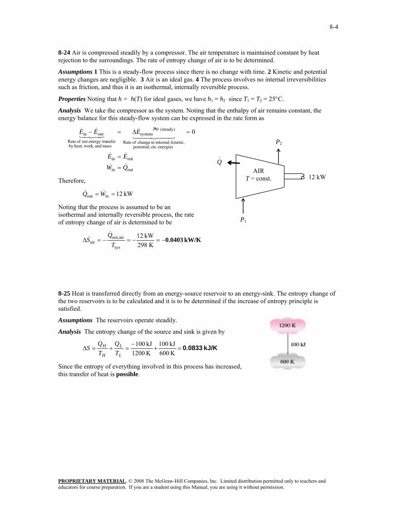
8-24 Air is compressed steadily by a compressor. The air temperature is maintained constant by heat rejection to the surroundings. The rate of entropy change of air is to be determined.
Assumptions 1 This is a steady-flow process since there is no change with time. 2 Kinetic and potential energy changes are negligible. 3 Air is an ideal gas. 4 The process involves no internal irreversibilities such as friction, and thus it is an isothermal, internally reversible process.
Properties Noting that h = h(T) for ideal gases, we have h1 = h2 since T1 = T2 = 25°C.
Analysis We take the compressor as the system. Noting that the enthalpy of air remains constant, the energy balance for this steady-flow system can be expressed in the rate form as
outin
outin
energies etc. potential, kinetic, internal,in change of Rate
(steady) 0system
mass and work,heat,by nsferenergy tranet of Rate
outin 0
QW
EE
EEE
&&
&&
44 344 21&
43421&&
=
=
=Δ=−
Therefore,
kW 12inout == WQ &&
Noting that the process is assumed to be an isothermal and internally reversible process, the rate of entropy change of air is determined to be
kW/K 0.0403−=−=−=ΔK 298
kW 12
sys
airout,air T
QS
&&
8-25 Heat is transferred directly from an energy-source reservoir to an energy-sink. The entropy change of the two reservoirs is to be calculated and it is to be determined if the increase of entropy principle is satisfied.
Assumptions The reservoirs operate steadily.
Analysis The entropy change of the source and sink is given by
kJ/K 0.0833=+−
=+=ΔK 600kJ 100
K 1200kJ 100
L
L
H
H
TQ
TQ
S
Since the entropy of everything involved in this process has increased, this transfer of heat is possible.
8-26 It is assumed that heat is transferred from a cold reservoir to the hot reservoir contrary to the Clausius statement of the second law. It is to be proven that this violates the increase in entropy principle.
Assumptions The reservoirs operate steadily.
Analysis According to the definition of the entropy, the entropy change of the high-temperature reservoir shown below is
kJ/K 08333.0K 1200
kJ 100===Δ
HH T
QS
and the entropy change of the low-temperature reservoir is
kJ/K 1667.0K 600kJ 100
−=−
==ΔL
L TQS
The total entropy change of everything involved with this system is then
kJ/K 0.0833−=−=Δ+Δ=Δ 1667.008333.0total LH SSS
which violates the increase in entropy principle since the entropy is decreasing, not increasing or staying fixed.
8-27 Heat is transferred from a hot reservoir to a cold reservoir. The entropy change of the two reservoirs is to be calculated and it is to be determined if the second law is satisfied.
Assumptions The reservoirs operate steadily.
Analysis The rate of entropy change of everything involved in this transfer of heat is given by
kW/K 0.00417=+−
=+=ΔK 300
kW 2K 800
kW 2
L
L
H
H
TQ
TQ
S&&
&
Since this rate is positive (i.e., the entropy increases as time passes), this transfer of heat is possible.
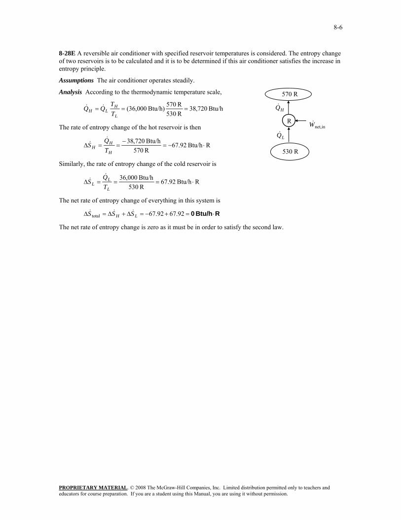
8-28E A reversible air conditioner with specified reservoir temperatures is considered. The entropy change of two reservoirs is to be calculated and it is to be determined if this air conditioner satisfies the increase in entropy principle.
Assumptions The air conditioner operates steadily.
Analysis According to the thermodynamic temperature scale,
Btu/h 720,38R 530R 570Btu/h) 000,36( ===
L
HLH T
TQQ &&
The rate of entropy change of the hot reservoir is then
RBtu/h 92.67R 570Btu/h 720,38
⋅−=−
==ΔH
HH T
QS
&&
Similarly, the rate of entropy change of the cold reservoir is
RBtu/h 92.67R 530Btu/h 000,36
⋅===ΔL
LL T
QS
&&
The net rate of entropy change of everything in this system is
RBtu/h 0 ⋅=+−=Δ+Δ=Δ 92.6792.67total LH SSS &&&
The net rate of entropy change is zero as it must be in order to satisfy the second law.
8-29 A reversible heat pump with specified reservoir temperatures is considered. The entropy change of two reservoirs is to be calculated and it is to be determined if this heat pump satisfies the increase in entropy principle.
Assumptions The heat pump operates steadily.
Analysis Since the heat pump is completely reversible, the combination of the coefficient of performance expression, first Law, and thermodynamic temperature scale gives
73.26)K 294/()K 283(1
1/1
1COP revHP, =−
=−
=HL TT
The power required to drive this heat pump, according to the coefficient of performance, is then
kW 741.326.73
kW 100COP revHP,
innet, === HQW
&&
According to the first law, the rate at which heat is removed from the low-temperature energy reservoir is
kW 26.96kW 741.3kW 100innet, =−=−= WQQ HL&&&
The rate at which the entropy of the high temperature reservoir changes, according to the definition of the entropy, is
kW/K 0.340===ΔK 294
kW 100
H
HH T
QS
&&
and that of the low-temperature reservoir is
kW/K 0.340−=−
==ΔK 283kW 26.96
L
LL T
QS
&&
The net rate of entropy change of everything in this system is
kW/K 0=−=Δ+Δ=Δ 340.0340.0total LH SSS &&&
as it must be since the heat pump is completely reversible.
8-30E Heat is transferred isothermally from the working fluid of a Carnot engine to a heat sink. The entropy change of the working fluid is given. The amount of heat transfer, the entropy change of the sink, and the total entropy change during the process are to be determined.
Analysis (a) This is a reversible isothermal process, and the entropy change during such a process is given by
ΔSQ
T=
Noting that heat transferred from the working fluid is equal to the heat transferred to the sink, the heat transfer become
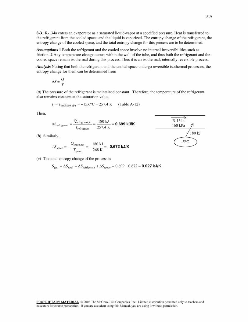
8-31 R-134a enters an evaporator as a saturated liquid-vapor at a specified pressure. Heat is transferred to the refrigerant from the cooled space, and the liquid is vaporized. The entropy change of the refrigerant, the entropy change of the cooled space, and the total entropy change for this process are to be determined.
Assumptions 1 Both the refrigerant and the cooled space involve no internal irreversibilities such as friction. 2 Any temperature change occurs within the wall of the tube, and thus both the refrigerant and the cooled space remain isothermal during this process. Thus it is an isothermal, internally reversible process.
Analysis Noting that both the refrigerant and the cooled space undergo reversible isothermal processes, the entropy change for them can be determined from
ΔSQ
T=
(a) The pressure of the refrigerant is maintained constant. Therefore, the temperature of the refrigerant also remains constant at the saturation value,
8-35 R-134a is expanded in a turbine during which the entropy remains constant. The enthalpy difference is to be determined.
Analysis The initial state is superheated vapor and thus
EES) (fromRBtu/lbm 23281.0
Btu/lbm 95.129
F175 psia 250
1
1
1
1 ⋅=
=
⎭⎬⎫
°==
sh
TP
The entropy is constant during the process. The final state is also superheated vapor and the enthalpy at this state is
EES) (fromBtu/lbm 95.106 RBtu/lbm 23281.0
F202
12
2 =⎭⎬⎫
⋅==°=
hss
T
Note that the properties at the inlet and exit states can also be determined from Table A-13E by interpolation but the values will not be as accurate as those by EES. The change in the enthalpy across the turbine is then
Btu/lbm 23.0−=−=−=Δ 95.12995.10612 hhh
8-36E A piston-cylinder device that is filled with water is heated. The total entropy change is to be determined.
Analysis The initial specific volume is
/lbmft 25.1lbm 2
ft 5.2 33
11 ===
mV
v
which is between vf and vg for 300 psia. The initial quality and the entropy are then (Table A-5E)
8-37 Water is compressed in a compressor during which the entropy remains constant. The final temperature and enthalpy are to be determined.
Analysis The initial state is superheated vapor and the entropy is
EES) (fromKkJ/kg 1531.8
kJ/kg 2800.7
kPa 35C160
1
1
1
1 ⋅=
=
⎭⎬⎫
=°=
sh
PT
Note that the properties can also be determined from Table A-6 by interpolation but the values will not be as accurate as those by EES. The final state is superheated vapor and the properties are (Table A-6)
K kJ/kg 1531.8 kPa 300
2
2
12
2
kJ/kg 3361.0C440.5
=°=
⎭⎬⎫
⋅===
hT
ssP
8-38E R-134a is expanded isentropically in a closed system. The heat transfer and work production are to be determined.
Assumptions 1 The system is stationary and thus the kinetic and potential energy changes are zero. 2 There are no work interactions involved other than the boundary work. 3 The thermal energy stored in the cylinder itself is negligible. 4 The compression or expansion process is quasi-equilibrium.
Analysis As there is no area under the process line shown on the T-s diagram and this process is reversible,
Btu 0=Q
The energy balance for this system can be expressed as
)(
)(
21out
12out
energies etc. potential, kinetic, internal,in Change
system
mass and work,heat,by nsferenergy traNet
outin
uumWuumUW
EEE
−=−=Δ=−
Δ=−4342143421
The initial state properties are
13E)-A (TableRBtu/lbm 22900.0
Btu/lbm 45.109
psia 100F100
1
1
1
1 ⋅=
=
⎭⎬⎫
=°=
su
PT
The final state properties for this isentropic process are (Table A-12E)
8-39 An insulated rigid tank contains a saturated liquid-vapor mixture of water at a specified pressure. An electric heater inside is turned on and kept on until all the liquid vaporized. The entropy change of the water during this process is to be determined.
Analysis From the steam tables (Tables A-4 through A-6)
8-40 CD EES A rigid tank is divided into two equal parts by a partition. One part is filled with compressed liquid water while the other side is evacuated. The partition is removed and water expands into the entire tank. The entropy change of the water during this process is to be determined.
Analysis The properties of the water are (Table A-4)
8-41 EES Problem 8-40 is reconsidered. The entropy generated is to be evaluated and plotted as a function of surroundings temperature, and the values of the surroundings temperatures that are valid for this problem are to be determined. The surrounding temperature is to vary from 0°C to 100°C.
Analysis The problem is solved using EES, and the results are tabulated and plotted below.
"Input Data" P[1]=300 [kPa] T[1]=60 [C] m=1.5 [kg] P[2]=15 [kPa] Fluid$='Steam_IAPWS' V[1]=m*spv[1] spv[1]=volume(Fluid$,T=T[1], P=P[1]) "specific volume of steam at state 1, m^3/kg" s[1]=entropy(Fluid$,T=T[1],P=P[1]) "entropy of steam at state 1, kJ/kgK" V[2]=2*V[1] "Steam expands to fill entire volume at state 2" "State 2 is identified by P[2] and spv[2]" spv[2]=V[2]/m "specific volume of steam at state 2, m^3/kg" s[2]=entropy(Fluid$,P=P[2],v=spv[2]) "entropy of steam at state 2, kJ/kgK" T[2]=temperature(Fluid$,P=P[2],v=spv[2]) DELTAS_sys=m*(s[2]-s[1]) "Total entopy change of steam, kJ/K" "What does the first law tell us about this problem?" "Conservation of Energy for the entire, closed system" E_in - E_out = DELTAE_sys "neglecting changes in KE and PE for the system:" DELTAE_sys=m*(intenergy(Fluid$, P=P[2], v=spv[2]) - intenergy(Fluid$,T=T[1],P=P[1])) E_in = 0 "How do you interpert the energy leaving the system, E_out? Recall this is a constant volume system." Q_out = E_out "What is the maximum value of the Surroundings temperature?" "The maximum possible value for the surroundings temperature occurs when we set S_gen = 0=Delta S_sys+sum(DeltaS_surr)" Q_net_surr=Q_out S_gen = 0 S_gen = DELTAS_sys+Q_net_surr/Tsurr "Establish a parametric table for the variables S_gen, Q_net_surr, T_surr, and DELTAS_sys. In the Parametric Table window select T_surr and insert a range of values. Then place '{' and '}' about the S_gen = 0 line; press F3 to solve the table. The results are shown in Plot Window 1. What values of T_surr are valid for this problem?"
8-42E A cylinder is initially filled with R-134a at a specified state. The refrigerant is cooled and condensed at constant pressure. The entropy change of refrigerant during this process is to be determined
Analysis From the refrigerant tables (Tables A-11E through A-13E),
RBtu/lbm 0.06039psia 120
F05
RBtu/lbm 0.22361F100psia 120
F90@22
2
11
1
⋅=≅⎭⎬⎫
=°=
⋅=⎭⎬⎫
°==
ofssPT
sTP
Then the entropy change of the refrigerant becomes
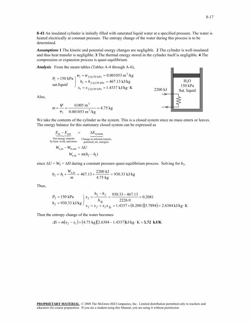
8-43 An insulated cylinder is initially filled with saturated liquid water at a specified pressure. The water is heated electrically at constant pressure. The entropy change of the water during this process is to be determined.
Assumptions 1 The kinetic and potential energy changes are negligible. 2 The cylinder is well-insulated and thus heat transfer is negligible. 3 The thermal energy stored in the cylinder itself is negligible. 4 The compression or expansion process is quasi-equilibrium.
Analysis From the steam tables (Tables A-4 through A-6),
KkJ/kg 1.4337
kJ/kg 467.13/kgm 0.001053
.kPa 150
kPa 150@1
kPa 150@1
3kPa 150@1
1
⋅====
==
⎭⎬⎫=
f
f
f
sshh
liquidsatP
vv
Also,
kg 4.75/kgm 0.001053
m 0.0053
3
1===
vVm
We take the contents of the cylinder as the system. This is a closed system since no mass enters or leaves. The energy balance for this stationary closed system can be expressed as
)( 12ine,
outb,ine,
energies etc. potential, kinetic, internal,in Change
system
mass and work,heat,by nsferenergy traNet
outin
hhmWUWW
EEE
−=
Δ=−
Δ=−4342143421
since ΔU + Wb = ΔH during a constant pressure quasi-equilibrium process. Solving for h2,
8-44 An insulated cylinder is initially filled with saturated R-134a vapor at a specified pressure. The refrigerant expands in a reversible manner until the pressure drops to a specified value. The final temperature in the cylinder and the work done by the refrigerant are to be determined.
Assumptions 1 The kinetic and potential energy changes are negligible. 2 The cylinder is well-insulated and thus heat transfer is negligible. 3 The thermal energy stored in the cylinder itself is negligible. 4 The process is stated to be reversible.
Analysis (a) This is a reversible adiabatic (i.e., isentropic) process, and thus s2 = s1. From the refrigerant tables (Tables A-11 through A-13),
KkJ/kg 0.91835
kJ/kg 246.79/kgm 0.025621
vaporsat.MPa 0.8
MPa 0.8@1
MPa 0.8@1
3MPa 0.8@1
1
⋅====
==
⎭⎬⎫=
g
g
g
ssuu
Pvv
Also,
kg 952.1/kgm 0.025621
m 0.053
3
1===
vVm
and
( )( ) kJ/kg 232.91171.450.987463.62
9874.067929.0
24761.091835.0MPa 0.4
22
22
12
2
=+=+=
=−
=−
=
⎭⎬⎫
==
fgf
fg
f
uxuus
ssx
ssP
C8.91°== MPa 0.4@sat2 TT
(b) We take the contents of the cylinder as the system. This is a closed system since no mass enters or leaves. The energy balance for this adiabatic closed system can be expressed as
)( 21outb,
outb,
energies etc. potential, kinetic, internal,in Change
system
mass and work,heat,by nsferenergy traNet
outin
uumWUW
EEE
−=
Δ=−
Δ=−4342143421
Substituting, the work done during this isentropic process is determined to be
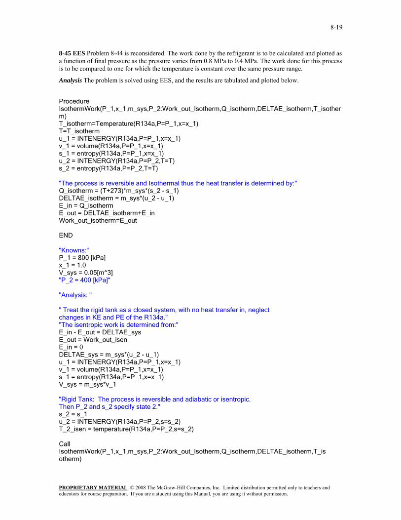
8-45 EES Problem 8-44 is reconsidered. The work done by the refrigerant is to be calculated and plotted as a function of final pressure as the pressure varies from 0.8 MPa to 0.4 MPa. The work done for this process is to be compared to one for which the temperature is constant over the same pressure range.
Analysis The problem is solved using EES, and the results are tabulated and plotted below.
Procedure IsothermWork(P_1,x_1,m_sys,P_2:Work_out_Isotherm,Q_isotherm,DELTAE_isotherm,T_isotherm) T_isotherm=Temperature(R134a,P=P_1,x=x_1) T=T_isotherm u_1 = INTENERGY(R134a,P=P_1,x=x_1) v_1 = volume(R134a,P=P_1,x=x_1) s_1 = entropy(R134a,P=P_1,x=x_1) u_2 = INTENERGY(R134a,P=P_2,T=T) s_2 = entropy(R134a,P=P_2,T=T) "The process is reversible and Isothermal thus the heat transfer is determined by:" Q_isotherm = (T+273)*m_sys*(s_2 - s_1) DELTAE_isotherm = m_sys*(u_2 - u_1) E_in = Q_isotherm E_out = DELTAE_isotherm+E_in Work_out_isotherm=E_out END "Knowns:" P_1 = 800 [kPa] x_1 = 1.0 V_sys = 0.05[m^3] "P_2 = 400 [kPa]" "Analysis: " " Treat the rigid tank as a closed system, with no heat transfer in, neglect changes in KE and PE of the R134a." "The isentropic work is determined from:" E_in - E_out = DELTAE_sys E_out = Work_out_isen E_in = 0 DELTAE_sys = m_sys*(u_2 - u_1) u_1 = INTENERGY(R134a,P=P_1,x=x_1) v_1 = volume(R134a,P=P_1,x=x_1) s_1 = entropy(R134a,P=P_1,x=x_1) V_sys = m_sys*v_1 "Rigid Tank: The process is reversible and adiabatic or isentropic. Then P_2 and s_2 specify state 2." s_2 = s_1 u_2 = INTENERGY(R134a,P=P_2,s=s_2) T_2_isen = temperature(R134a,P=P_2,s=s_2) Call IsothermWork(P_1,x_1,m_sys,P_2:Work_out_Isotherm,Q_isotherm,DELTAE_isotherm,T_isotherm)
8-46 Saturated Refrigerant-134a vapor at 160 kPa is compressed steadily by an adiabatic compressor. The minimum power input to the compressor is to be determined.
Assumptions 1 This is a steady-flow process since there is no change with time. 2 Kinetic and potential energy changes are negligible. 3 The device is adiabatic and thus heat transfer is negligible.
Analysis The power input to an adiabatic compressor will be a minimum when the compression process is reversible. For the reversible adiabatic process we have s2 = s1. From the refrigerant tables (Tables A-11 through A-13),
kJ/kg 277.06kPa 009
KkJ/kg 0.9419kJ/kg 241.11
/kgm 0.12348
vaporsat.kPa 160
212
2
kPa 160@1
kPa 160@1
3kPa 160@1
1
=⎭⎬⎫
==
⋅======
⎭⎬⎫=
hss
P
sshh
P
g
g
gvv
Also,
kg/s 0.27kg/min 16.20/kgm 0.12348
/minm 23
3
1
1 ====v
V&&m
There is only one inlet and one exit, and thus & & &m m m1 2= = . We take the compressor as the system, which is a control volume since mass crosses the boundary. The energy balance for this steady-flow system can be expressed in the rate form as
outin
energies etc. potential, kinetic, internal,in change of Rate
(steady) 0system
mass and work,heat,by nsferenergy tranet of Rate
outin 0
EE
EEE
&&
44 344 21&
43421&&
=
=Δ=−
& & & &
& & ( )
W mh mh Q ke pe
W m h h
in
in
(since 0)+ = ≅ ≅ ≅
= −1 2
2 1
Δ Δ
Substituting, the minimum power supplied to the compressor is determined to be
8-47 An insulated cylinder is initially filled with superheated steam at a specified state. The steam is compressed in a reversible manner until the pressure drops to a specified value. The work input during this process is to be determined.
Assumptions 1 The kinetic and potential energy changes are negligible. 2 The cylinder is well-insulated and thus heat transfer is negligible. 3 The thermal energy stored in the cylinder itself is negligible. 4 The process is stated to be reversible.
Analysis This is a reversible adiabatic (i.e., isentropic) process, and thus s2 = s1. From the steam tables (Tables A-4 through A-6),
kJ/kg 2773.8MPa 1
KkJ/kg 7.0792kJ/kg 2571.0
/kgm 0.63402
C150kPa 300
212
2
1
1
31
1
1
=⎭⎬⎫
==
⋅===
⎭⎬⎫
°==
uss
Ps
uTP
v
Also,
kg 0.0789/kgm 0.63402
m 0.053
3
1===
vVm
We take the contents of the cylinder as the system. This is a closed system since no mass enters or leaves. The energy balance for this adiabatic closed system can be expressed as
)( 12inb,
energies etc. potential, kinetic, internal,in Change
system
mass and work,heat,by nsferenergy traNet
outin
uumUW
EEE
−=Δ=
Δ=−4342143421
Substituting, the work input during this adiabatic process is determined to be
8-48 EES Problem 8-47 is reconsidered. The work done on the steam is to be determined and plotted as a function of final pressure as the pressure varies from 300 kPa to 1 MPa.
Analysis The problem is solved using EES, and the results are tabulated and plotted below.
"Knowns:" P_1 = 300 [kPa] T_1 = 150 [C] V_sys = 0.05 [m^3] "P_2 = 1000 [kPa]" "Analysis: " Fluid$='Steam_IAPWS' " Treat the piston-cylinder as a closed system, with no heat transfer in, neglect changes in KE and PE of the Steam. The process is reversible and adiabatic thus isentropic." "The isentropic work is determined from:" E_in - E_out = DELTAE_sys E_out = 0 [kJ] E_in = Work_in DELTAE_sys = m_sys*(u_2 - u_1) u_1 = INTENERGY(Fluid$,P=P_1,T=T_1) v_1 = volume(Fluid$,P=P_1,T=T_1) s_1 = entropy(Fluid$,P=P_1,T=T_1) V_sys = m_sys*v_1 " The process is reversible and adiabatic or isentropic. Then P_2 and s_2 specify state 2." s_2 = s_1 u_2 = INTENERGY(Fluid$,P=P_2,s=s_2) T_2_isen = temperature(Fluid$,P=P_2,s=s_2)
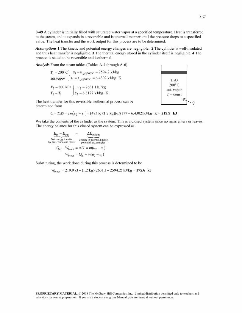
8-49 A cylinder is initially filled with saturated water vapor at a specified temperature. Heat is transferred to the steam, and it expands in a reversible and isothermal manner until the pressure drops to a specified value. The heat transfer and the work output for this process are to be determined.
Assumptions 1 The kinetic and potential energy changes are negligible. 2 The cylinder is well-insulated and thus heat transfer is negligible. 3 The thermal energy stored in the cylinder itself is negligible. 4 The process is stated to be reversible and isothermal.
Analysis From the steam tables (Tables A-4 through A-6),
KkJ/kg 6.8177kJ/kg 2631.1kPa 800
KkJ/kg 6.4302kJ/kg 2594.2
.C200
2
2
12
2
C200@1
C200@11
⋅==
⎭⎬⎫
==
⋅====
⎭⎬⎫°=
°
°
su
TTP
ssuu
vaporsatT
g
g
The heat transfer for this reversible isothermal process can be determined from
We take the contents of the cylinder as the system. This is a closed system since no mass enters or leaves. The energy balance for this closed system can be expressed as
)()(
12inoutb,
12outb,in
energies etc. potential, kinetic, internal,in Change
system
mass and work,heat,by nsferenergy traNet
outin
uumQWuumUWQ
EEE
−−=
−=Δ=−
Δ=−4342143421
Substituting, the work done during this process is determined to be
8-50 EES Problem 8-49 is reconsidered. The heat transferred to the steam and the work done are to be determined and plotted as a function of final pressure as the pressure varies from the initial value to the final value of 800 kPa.
Analysis The problem is solved using EES, and the results are tabulated and plotted below.
"Knowns:" T_1 = 200 [C] x_1 = 1.0 m_sys = 1.2 [kg] {P_2 = 800"[kPa]"} "Analysis: " Fluid$='Steam_IAPWS' " Treat the piston-cylinder as a closed system, neglect changes in KE and PE of the Steam. The process is reversible and isothermal ." T_2 = T_1 E_in - E_out = DELTAE_sys E_in = Q_in E_out = Work_out DELTAE_sys = m_sys*(u_2 - u_1) P_1 = pressure(Fluid$,T=T_1,x=1.0) u_1 = INTENERGY(Fluid$,T=T_1,x=1.0) v_1 = volume(Fluid$,T=T_1,x=1.0) s_1 = entropy(Fluid$,T=T_1,x=1.0) V_sys = m_sys*v_1 " The process is reversible and isothermal. Then P_2 and T_2 specify state 2." u_2 = INTENERGY(Fluid$,P=P_2,T=T_2) s_2 = entropy(Fluid$,P=P_2,T=T_2) Q_in= (T_1+273)*m_sys*(s_2-s_1)
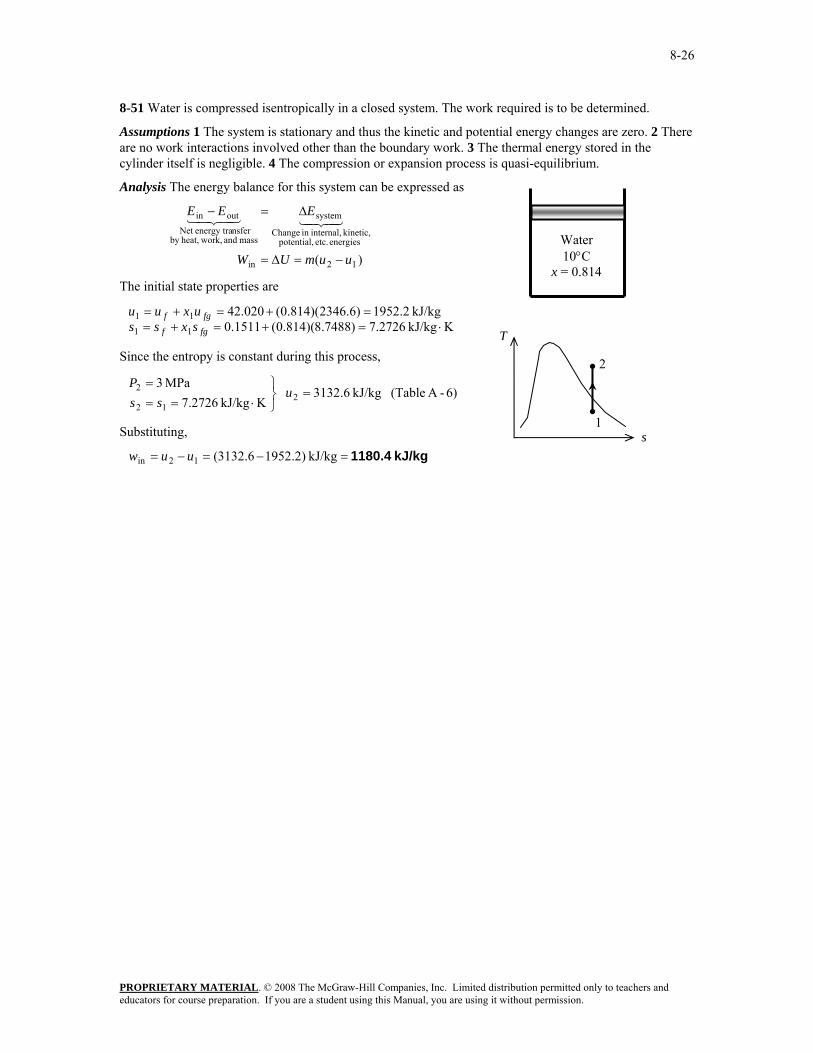
8-51 Water is compressed isentropically in a closed system. The work required is to be determined.
Assumptions 1 The system is stationary and thus the kinetic and potential energy changes are zero. 2 There are no work interactions involved other than the boundary work. 3 The thermal energy stored in the cylinder itself is negligible. 4 The compression or expansion process is quasi-equilibrium.
Analysis The energy balance for this system can be expressed as
)( 12in
energies etc. potential, kinetic, internal,in Change
8-52 R-134a undergoes an isothermal process in a closed system. The work and heat transfer are to be determined.
Assumptions 1 The system is stationary and thus the kinetic and potential energy changes are zero. 2 There are no work interactions involved other than the boundary work. 3 The thermal energy stored in the cylinder itself is negligible. 4 The compression or expansion process is quasi-equilibrium.
Analysis The energy balance for this system can be expressed as
)( 12outin
energies etc. potential, kinetic, internal,in Change
system
mass and work,heat,by nsferenergy traNet
outin
uumUQW
EEE
−=Δ=−
Δ=−4342143421
The initial state properties are
13)-A (TableKkJ/kg 0134.1
kJ/kg 74.246
C20 kPa 240
1
1
1
1 ⋅=
=
⎭⎬⎫
°==
su
TP
For this isothermal process, the final state properties are (Table A-11)
8-57 The change in the entropy of R-134a as it is heated at constant pressure is to be calculated using the relation ds = (δQ /T) int rev, and it is to be verified by using R-134a tables.
Analysis As R-134a is converted from a saturated liquid to a saturated vapor, both the pressure and temperature remains constant. Then, the relation ds = (δQ /T) int rev reduces to
Tdhds =
When this result is integrated between the saturated liquid and saturated vapor states, the result is (Table A-12)
KkJ/kg 0.78321 ⋅=
+−=
=−
=−
K )15.27309.10(kJ/kg 03.206
kPa 200 @sat
kPa 200@
Th
Thh
ss fgfgfg
Finding the result directly from the R-134a tables
8-58 Steam is expanded in an isentropic turbine. The work produced is to be determined.
Assumptions 1 This is a steady-flow process since there is no change with time. 2 The process is isentropic (i.e., reversible-adiabatic).
Analysis There is only one inlet and one exit, and thus mmm &&& == 21 . We take the turbine as the system, which is a control volume since mass crosses the boundary. The energy balance for this steady-flow system can be expressed in the rate form as
outin
energies etc. potential, kinetic, internal,in change of Rate
(steady) 0system
mass and work,heat,by nsferenergy tranet of Rate
outin 0
EE
EEE
&&
444 344 21&
43421&&
=
=Δ=−
)( 21out
out21
hhmW
Whmhm
−=
+=
&&
&&&
The inlet state properties are
6)-A (TableKkJ/kg 9938.6
kJ/kg 9.3159
C360 MPa 2
1
1
1
1 ⋅=
=
⎭⎬⎫
°==
sh
TP
For this isentropic process, the final state properties are (Table A-5)
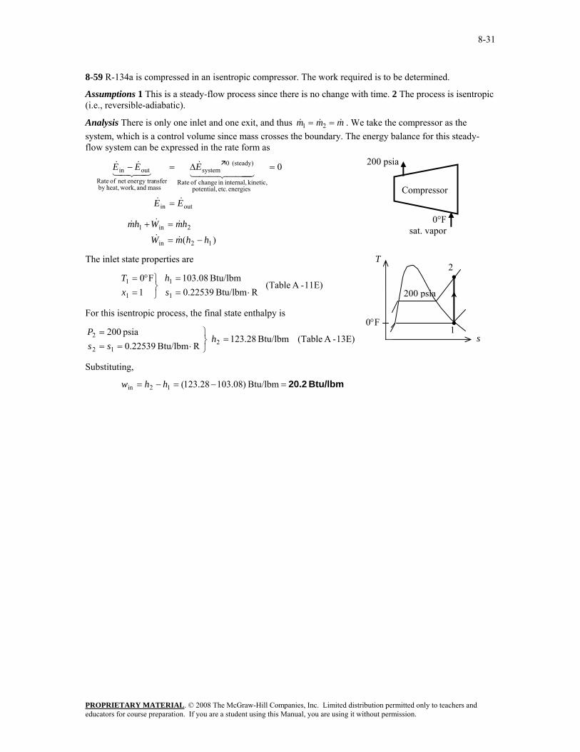
8-59 R-134a is compressed in an isentropic compressor. The work required is to be determined.
Assumptions 1 This is a steady-flow process since there is no change with time. 2 The process is isentropic (i.e., reversible-adiabatic).
Analysis There is only one inlet and one exit, and thus mmm &&& == 21 . We take the compressor as the system, which is a control volume since mass crosses the boundary. The energy balance for this steady-flow system can be expressed in the rate form as
outin
energies etc. potential, kinetic, internal,in change of Rate
(steady) 0system
mass and work,heat,by nsferenergy tranet of Rate
outin 0
EE
EEE
&&
444 344 21&
43421&&
=
=Δ=−
)( 12in
2in1
hhmW
hmWhm
−=
=+
&&
&&&
The inlet state properties are
11E)-A (TableRBtu/lbm 22539.0
Btu/lbm 08.103
1F0
1
1
1
1 ⋅=
=
⎭⎬⎫
=°=
sh
xT
For this isentropic process, the final state enthalpy is
8-60 Steam is expanded in an isentropic turbine. The work produced is to be determined.
Assumptions 1 This is a steady-flow process since there is no change with time. 2 The process is isentropic (i.e., reversible-adiabatic).
Analysis There is one inlet and two exits. We take the turbine as the system, which is a control volume since mass crosses the boundary. The energy balance for this steady-flow system can be expressed in the rate form as
outin
energies etc. potential, kinetic, internal,in change of Rate
(steady) 0system
mass and work,heat,by nsferenergy tranet of Rate
outin 0
EE
EEE
&&
444 344 21&
43421&&
=
=Δ=−
332211out
out332211
hmhmhmW
Whmhmhm&&&&
&&&&
−−=
++=
From a mass balance,
kg/s 75.4)kg/s 5)(95.0(95.0
kg/s 25.0)kg/s 5)(05.0(05.0
13
12
===
===
mm
mm
&&
&&
Noting that the expansion process is isentropic, the enthalpies at three states are determined as follows:
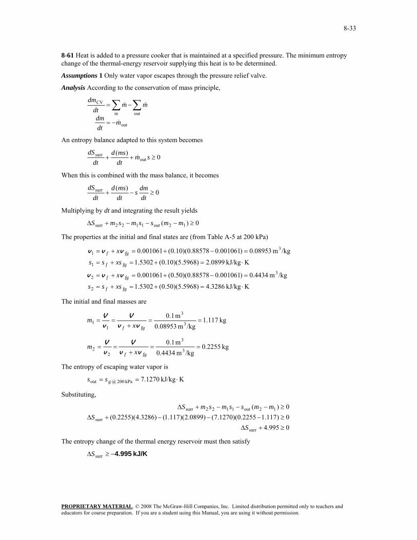
8-61 Heat is added to a pressure cooker that is maintained at a specified pressure. The minimum entropy change of the thermal-energy reservoir supplying this heat is to be determined.
Assumptions 1 Only water vapor escapes through the pressure relief valve.
Analysis According to the conservation of mass principle,
out
outin
CV
mdtdm
mmdt
dm
&
&&
−=
−= ∑∑
An entropy balance adapted to this system becomes
0)(
outsurr ≥++ sm
dtmsd
dtdS
&
When this is combined with the mass balance, it becomes
0)(surr ≥−+
dtdms
dtmsd
dtdS
Multiplying by dt and integrating the result yields
0)( 12out1122surr ≥−−−+Δ mmssmsmS
The properties at the initial and final states are (from Table A-5 at 200 kPa)
8-62 Heat is added to a pressure cooker that is maintained at a specified pressure. Work is also done on water. The minimum entropy change of the thermal-energy reservoir supplying this heat is to be determined.
Assumptions 1 Only water vapor escapes through the pressure relief valve.
Analysis According to the conservation of mass principle,
out
outin
CV
mdtdm
mmdt
dm
&
&&
−=
−= ∑∑
An entropy balance adapted to this system becomes
0)(
outsurr ≥++ sm
dtmsd
dtdS
&
When this is combined with the mass balance, it becomes
0)(surr ≥−+
dtdms
dtmsd
dtdS
Multiplying by dt and integrating the result yields
0)( 12out1122surr ≥−−−+Δ mmssmsmS
The properties at the initial and final states are (from Table A-5 at 200 kPa)
8-63 A cylinder is initially filled with saturated water vapor mixture at a specified temperature. Steam undergoes a reversible heat addition and an isentropic process. The processes are to be sketched and heat transfer for the first process and work done during the second process are to be determined.
Assumptions 1 The kinetic and potential energy changes are negligible. 2 The thermal energy stored in the cylinder itself is negligible. 3 Both processes are reversible.
Analysis (b) From the steam tables (Tables A-4 through A-6),
kJ/kg 2247.9kPa 15
KkJ/kg 3542.7kJ/kg 2506.0
kJ/kg 2675.6
1C100
kJ/kg 4.1547)4.2256)(5.0(17.4195.0
C100
323
3
2
2
2
2
2
11
=⎭⎬⎫
==
⋅====
==
⎭⎬⎫
=°=
=+=+=⎭⎬⎫
=°=
uss
P
ssuu
hh
xT
xhhhxT
g
g
g
fgf
We take the contents of the cylinder as the system. This is a closed system since no mass enters or leaves. The energy balance for this closed system can be expressed as
)( 12outb,in
energies etc. potential, kinetic, internal,in Change
8-64 Steam expands in an adiabatic turbine. Steam leaves the turbine at two different pressures. The process is to be sketched on a T-s diagram and the work done by the steam per unit mass of the steam at the inlet are to be determined.
Assumptions 1 The kinetic and potential energy changes are negligible.
Analysis (b) From the steam tables (Tables A-4 through A-6),
831.0kJ/kg 6.2179kPa 10
kJ/kg 3.2921MPa 1
KkJ/kg 8826.6
kJ/kg 1.3423MPa 6
C005
3
3
13
3
212
2
1
1
1
1
==
⎭⎬⎫
==
=⎭⎬⎫
==
⋅==
⎭⎬⎫
=°=
s
s
s
xh
ssP
hss
Ps
hPT
A mass balance on the control volume gives
321 mmm &&& += where 13
12
9.01.0mmmm&&
&&
==
We take the turbine as the system, which is a control volume. The energy balance for this steady-flow system can be expressed in the rate form as
3121out,11
3322out,11
outin
9.01.0 hmhmWhm
hmhmWhm
EE
s
s
&&&&
&&&&
&&
++=
++=
=
or
kJ/kg 3.1169)6.2179)(9.0()3.2921)(1.0(1.3423
9.01.09.01.0
321out,
32out,1
=−−=
−−=
++=
hhhwhhwh
s
s
The actual work output per unit mass of steam at the inlet is
kJ/kg 993.9=== )kJ/kg 3.1169)(85.0(out,out sT ww η
8-65E An insulated rigid can initially contains R-134a at a specified state. A crack develops, and refrigerant escapes slowly. The final mass in the can is to be determined when the pressure inside drops to a specified value.
Assumptions 1 The can is well-insulated and thus heat transfer is negligible. 2 The refrigerant that remains in the can underwent a reversible adiabatic process.
Analysis Noting that for a reversible adiabatic (i.e., isentropic) process, s1 = s2, the properties of the refrigerant in the can are (Tables A-11E through A-13E)
( )( ) /lbmft 0.54530.011822.27720.23550.01182
2355.019962.0
02605.007306.0psia 02
RBtu/lbm 0.07306F07psia 140
322
22
12
2
F07@11
1
=−+=+=
=−
=−
=
⎭⎬⎫
==
⋅=≅⎭⎬⎫
°==
°
fgf
fg
f
f
xs
ssx
ssP
ssTP
vvv
Thus the final mass of the refrigerant in the can is
8-66C No, because entropy is not a conserved property.
8-67 A hot copper block is dropped into water in an insulated tank. The final equilibrium temperature of the tank and the total entropy change are to be determined.
Assumptions 1 Both the water and the copper block are incompressible substances with constant specific heats at room temperature. 2 The system is stationary and thus the kinetic and potential energies are negligible. 3 The tank is well-insulated and thus there is no heat transfer.
Properties The density and specific heat of water at 25°C are ρ = 997 kg/m3 and cp = 4.18 kJ/kg.°C. The specific heat of copper at 27°C is cp = 0.386 kJ/kg.°C (Table A-3).
Analysis We take the entire contents of the tank, water + copper block, as the system. This is a closed system since no mass crosses the system boundary during the process. The energy balance for this system can be expressed as
U
EEE
Δ=
Δ=−
0energies etc. potential,
kinetic, internal,in Change
system
mass and work,heat,by nsferenergy traNet
outin 4342143421
or,
0waterCu =Δ+Δ UU
0)]([)]([ water12Cu12 =−+− TTmcTTmc
where
kg 119.6)m 0.120)(kg/m 997( 33water === Vρm
Using specific heat values for copper and liquid water at room temperature and substituting,
8-68 Computer chips are cooled by placing them in saturated liquid R-134a. The entropy changes of the chips, R-134a, and the entire system are to be determined.
Assumptions 1 The system is stationary and thus the kinetic and potential energy changes are zero. 2 There are no work interactions involved. 3 There is no heat transfer between the system and the surroundings.
Analysis (a) The energy balance for this system can be expressed as
[ ] [ ][ ] [ ] 134a-R12chips21
134a-R12chips12
energies etc. potential, kinetic, internal,in Change
The mass of the refrigerant vaporized during this heat exchange process is
kg 0008679.0kJ/kg 207.40kJ 18.0
C40@
134aR134aRg,2 ===
−=
°−
−−
fgfg uQ
uuQ
m
Only a small fraction of R-134a is vaporized during the process. Therefore, the temperature of R-134a remains constant during the process. The change in the entropy of the R-134a is (at -40°F from Table A-11)
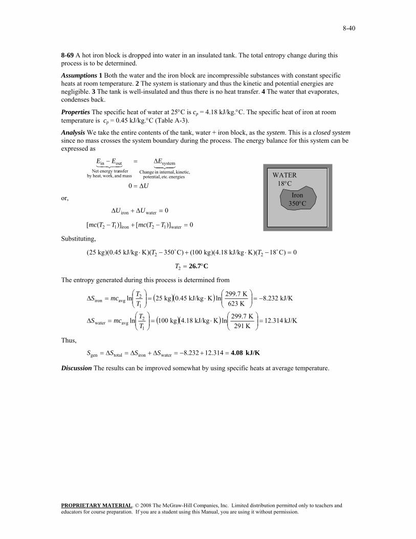
8-69 A hot iron block is dropped into water in an insulated tank. The total entropy change during this process is to be determined.
Assumptions 1 Both the water and the iron block are incompressible substances with constant specific heats at room temperature. 2 The system is stationary and thus the kinetic and potential energies are negligible. 3 The tank is well-insulated and thus there is no heat transfer. 4 The water that evaporates, condenses back.
Properties The specific heat of water at 25°C is cp = 4.18 kJ/kg.°C. The specific heat of iron at room temperature is cp = 0.45 kJ/kg.°C (Table A-3).
Analysis We take the entire contents of the tank, water + iron block, as the system. This is a closed system since no mass crosses the system boundary during the process. The energy balance for this system can be expressed as
8-70 An aluminum block is brought into contact with an iron block in an insulated enclosure. The final equilibrium temperature and the total entropy change for this process are to be determined.
Assumptions 1 Both the aluminum and the iron block are incompressible substances with constant specific heats. 2 The system is stationary and thus the kinetic and potential energies are negligible. 3 The system is well-insulated and thus there is no heat transfer.
Properties The specific heat of aluminum at the anticipated average temperature of 450 K is cp = 0.973 kJ/kg.°C. The specific heat of iron at room temperature (the only value available in the tables) is cp = 0.45 kJ/kg.°C (Table A-3).
Analysis We take the iron+aluminum blocks as the system, which is a closed system. The energy balance for this system can be expressed as
8-71 EES Problem 8-70 is reconsidered. The effect of the mass of the iron block on the final equilibrium temperature and the total entropy change for the process is to be studied. The mass of the iron is to vary from 1 to 10 kg. The equilibrium temperature and the total entropy change are to be plotted as a function of iron mass.
Analysis The problem is solved using EES, and the results are tabulated and plotted below.
"Knowns:" T_1_iron = 100 [C] {m_iron = 20 [kg]} T_1_al = 200 [C] m_al = 20 [kg] C_al = 0.973 [kJ/kg-K] "FromTable A-3 at the anticipated average temperature of 450 K." C_iron= 0.45 [kJ/kg-K] "FromTable A-3 at room temperature, the only value available." "Analysis: " " Treat the iron plus aluminum as a closed system, with no heat transfer in, no work out, neglect changes in KE and PE of the system. " "The final temperature is found from the energy balance." E_in - E_out = DELTAE_sys E_out = 0 E_in = 0 DELTAE_sys = m_iron*DELTAu_iron + m_al*DELTAu_al DELTAu_iron = C_iron*(T_2_iron - T_1_iron) DELTAu_al = C_al*(T_2_al - T_1_al) "the iron and aluminum reach thermal equilibrium:" T_2_iron = T_2 T_2_al = T_2 DELTAS_iron = m_iron*C_iron*ln((T_2_iron+273) / (T_1_iron+273)) DELTAS_al = m_al*C_al*ln((T_2_al+273) / (T_1_al+273)) DELTAS_total = DELTAS_iron + DELTAS_al
8-72 An iron block and a copper block are dropped into a large lake. The total amount of entropy change when both blocks cool to the lake temperature is to be determined.
Assumptions 1 The water, the iron block and the copper block are incompressible substances with constant specific heats at room temperature. 2 Kinetic and potential energies are negligible.
Properties The specific heats of iron and copper at room temperature are ciron = 0.45 kJ/kg.°C and ccopper = 0.386 kJ/kg.°C (Table A-3).
Analysis The thermal-energy capacity of the lake is very large, and thus the temperatures of both the iron and the copper blocks will drop to the lake temperature (15°C) when the thermal equilibrium is established. Then the entropy changes of the blocks become
( )( )
( )( ) kJ/K 1.571K 353K 288lnKkJ/kg 0.386kg 20ln
kJ/K 4.579K 353K 288lnKkJ/kg 0.45kg 50ln
1
2avgcopper
1
2avgiron
−=⎟⎟⎠
⎞⎜⎜⎝
⎛⋅=⎟⎟
⎠
⎞⎜⎜⎝
⎛=Δ
−=⎟⎟⎠
⎞⎜⎜⎝
⎛⋅=⎟⎟
⎠
⎞⎜⎜⎝
⎛=Δ
TTmcS
TTmcS
We take both the iron and the copper blocks, as the system. This is a closed system since no mass crosses the system boundary during the process. The energy balance for this system can be expressed as
copperironout
energies etc. potential, kinetic, internal,in Change
8-73 An adiabatic pump is used to compress saturated liquid water in a reversible manner. The work input is to be determined by different approaches.
Assumptions 1 Steady operating conditions exist. 2 Kinetic and potential energy changes are negligible. 3 Heat transfer to or from the fluid is negligible.
Analysis The properties of water at the inlet and exit of the pump are (Tables A-4 through A-6)
/kgm 001004.0kJ/kg 90.206MPa 15
/kgm 001010.0kJ/kg 6492.0kJ/kg 81.191
0kPa 10
32
2
12
2
31
1
1
1
1
==
⎭⎬⎫
==
===
⎭⎬⎫
==
v
v
hss
P
sh
xP
(a) Using the entropy data from the compressed liquid water table
kJ/kg 15.10=−=−= 81.19190.20612P hhw
(b) Using inlet specific volume and pressure values
kJ/kg 15.14=−=−= kPa)100/kg)(15,00m 001010.0()( 3121P PPw v
Error = 0.3%
(b) Using average specific volume and pressure values
[ ] kJ/kg 15.10=−+=−= kPa)10(15,000/kgm )001004.0001010.0(2/1)( 312avgP PPw v
Error = 0%
Discussion The results show that any of the method may be used to calculate reversible pump work.
8-75C For an ideal gas, dh = cp dT and v = RT/P. From the second Tds relation,
P
dPRTdTc
TdP
PRT
TdPc
TdPv
Tdhds p
p −=−=−=
Integrating,
⎟⎟⎠
⎞⎜⎜⎝
⎛−⎟⎟
⎠
⎞⎜⎜⎝
⎛=−
1
2
1
212 lnln
PP
RTT
css p
Since cp is assumed to be constant.
8-76C No. The entropy of an ideal gas depends on the pressure as well as the temperature.
8-77C Setting Δs = 0 gives
pCR
pp P
PTT
PP
cR
TT
PP
RTT
c ⎟⎟⎠
⎞⎜⎜⎝
⎛=⎯→⎯⎟⎟
⎠
⎞⎜⎜⎝
⎛=⎟⎟
⎠
⎞⎜⎜⎝
⎛⎯→⎯=⎟⎟
⎠
⎞⎜⎜⎝
⎛−⎟⎟
⎠
⎞⎜⎜⎝
⎛
1
2
1
2
1
2
1
2
1
2
1
2 lnln0lnln
But
( ) kk
pp
p
p PP
TTcck
kk
kccc
cR
1
1
2
1
2 ,Thus./ since 111 −
⎟⎟⎠
⎞⎜⎜⎝
⎛==
−=−=
−= v
v
8-78C The Pr and vr are called relative pressure and relative specific volume, respectively. They are derived for isentropic processes of ideal gases, and thus their use is limited to isentropic processes only.
8-79C The entropy of a gas can change during an isothermal process since entropy of an ideal gas depends on the pressure as well as the temperature.
8-80C The entropy change relations of an ideal gas simplify to
Δs = cp ln(T2/T1) for a constant pressure process
and Δs = cv ln(T2/T1) for a constant volume process.
Noting that cp > cv, the entropy change will be larger for a constant pressure process.
8-81 The entropy difference between the two states of oxygen is to be determined.
Assumptions Oxygen is an ideal gas with constant specific heats.
Properties The specific heat of oxygen at the average temperature of (39+337)/2=188°C=461 K is cp = 0.960 kJ/kg⋅K (Table A-2b).
Analysis From the entropy change relation of an ideal gas,
KkJ/kg 0.6436 ⋅=−++
⋅=−=Δ 0273)K(39273)K337(K)lnkJ/kg (0.960lnln
1
2
1
2oxygen P
PR
TT
cs p
since the pressure is same at the initial and final states.
8-82 The entropy changes of helium and nitrogen is to be compared for the same initial and final states.
Assumptions Helium and nitrogen are ideal gases with constant specific heats.
Properties The properties of helium are cp = 5.1926 kJ/kg⋅K, R = 2.0769 kJ/kg⋅K (Table A-2a). The specific heat of nitrogen at the average temperature of (427+27)/2=227°C=500 K is cp = 1.056 kJ/kg⋅K (Table A-2b). The gas constant of nitrogen is R = 0.2968 kJ/kg⋅K (Table A-2a).
Analysis From the entropy change relation of an ideal gas,
KkJ/kg 0.3826 ⋅=
⋅−++
⋅=
−=Δ
kPa 2000kPa 200K)lnkJ/kg (2.0769
273)K(427273)K27(
K)lnkJ/kg (5.1926
lnln1
2
1
2He P
PR
TT
cs p
KkJ/kg 0.2113 ⋅−=
⋅−++
⋅=
−=Δ
kPa 2000kPa 200K)lnkJ/kg (0.2968
273)K(427273)K27(K)lnkJ/kg (1.056
lnln1
2
1
2N2 P
PR
TT
cs p
Hence, helium undergoes the largest change in entropy.
8-83E The entropy change of air during an expansion process is to be determined.
Assumptions Air is an ideal gas with constant specific heats.
Properties The specific heat of air at the average temperature of (500+50)/2=275°F is cp = 0.243 Btu/lbm⋅R (Table A-2Eb). The gas constant of air is R = 0.06855 Btu/lbm⋅R (Table A-2Ea).
Analysis From the entropy change relation of an ideal gas,
RBtu/lbm 0.1062 ⋅−=
⋅−++
⋅=
−=Δ
psia 200psia 100R)lnBtu/lbm (0.06855
)R460(500)R46050(R)lnBtu/lbm (0.243
lnln1
2
1
2air P
PR
TT
cs p
8-84 The final temperature of air when it is expanded isentropically is to be determined.
Assumptions Air is an ideal gas with constant specific heats.
Properties The specific heat ratio of air at an anticipated average temperature of 550 K is k = 1.381 (Table A-2b).
Analysis From the isentropic relation of an ideal gas under constant specific heat assumption,
K 397=⎟⎠⎞
⎜⎝⎛+=⎟⎟
⎠
⎞⎜⎜⎝
⎛=
− 381.1/381.0/)1(
1
212 kPa 1000
kPa 100K) 273(477kk
PP
TT
Discussion The average air temperature is (750+397.4)/2=573.7 K, which is sufficiently close to the assumed average temperature of 550 K.
8-85E The final temperature of air when it is expanded isentropically is to be determined.
Assumptions Air is an ideal gas with constant specific heats.
Properties The specific heat ratio of air at an anticipated average temperature of 300°F is k = 1.394 (Table A-2Eb).
Analysis From the isentropic relation of an ideal gas under constant specific heat assumption,
R 609=⎟⎟⎠
⎞⎜⎜⎝
⎛+=⎟⎟
⎠
⎞⎜⎜⎝
⎛=
− 394.1/394.0/)1(
1
212 psia 100
psia 20R) 460(500kk
PP
TT
Discussion The average air temperature is (960+609)/2=785 R=325°F, which is sufficiently close to the assumed average temperature of 300°F.
8-88 An insulated cylinder initially contains air at a specified state. A resistance heater inside the cylinder is turned on, and air is heated for 15 min at constant pressure. The entropy change of air during this process is to be determined for the cases of constant and variable specific heats.
Assumptions At specified conditions, air can be treated as an ideal gas.
Properties The gas constant of air is R = 0.287 kJ/kg.K (Table A-1).
Analysis The mass of the air and the electrical work done during this process are
( )( )
( )( )( )( ) kJ 180s 6015kJ/s 0.2
kg 0.4325K 290K/kgmkPa 0.287
m 0.3kPa 120
ine,ine,
3
3
1
11
=×=Δ=
=⋅⋅
==
tWWRTPm
&
V
The energy balance for this stationary closed system can be expressed as
)()( 1212ine,outb,ine,
energies etc. potential, kinetic, internal,in Change
system
mass and work,heat,by nsferenergy traNet
outin
TTchhmWUWW
EEE
p −≅−=⎯→⎯Δ=−
Δ=−4342143421
since ΔU + Wb = ΔH during a constant pressure quasi-equilibrium process.
(a) Using a constant cp value at the anticipated average temperature of 450 K, the final temperature becomes
Thus, ( )( ) K 698KkJ/kg 1.02kg 0.4325
kJ 180K 290ine,12 =
⋅+=+=
pmcW
TT
Then the entropy change becomes
( )
( )( ) kJ/K0.387 K 290K 698ln KkJ/kg 1.020kg 0.4325
lnlnln1
2avg,
0
1
2
1
2avg,12sys
=⎟⎟⎠
⎞⎜⎜⎝
⎛⋅=
=⎟⎟⎠
⎞⎜⎜⎝
⎛−=−=Δ
TTmc
PPR
TTcmssmS pp
(b) Assuming variable specific heats,
( ) kJ/kg 706.34kg 0.4325
kJ 180kJ/kg 290.16ine,1212ine, =+=+=⎯→⎯−=
mW
hhhhmW
From the air table (Table A-21, we read s2o = 2.5628 kJ/kg·K corresponding to this h2 value. Then,
8-89 A cylinder contains N2 gas at a specified pressure and temperature. The gas is compressed polytropically until the volume is reduced by half. The entropy change of nitrogen during this process is to be determined.
Assumptions 1 At specified conditions, N2 can be treated as an ideal gas. 2 Nitrogen has constant specific heats at room temperature.
Properties The gas constant of nitrogen is R = 0.297 kJ/kg.K (Table A-1). The constant volume specific heat of nitrogen at room temperature is cv = 0.743 kJ/kg.K (Table A-2).
8-90 EES Problem 8-89 is reconsidered. The effect of varying the polytropic exponent from 1 to 1.4 on the entropy change of the nitrogen is to be investigated, and the processes are to be shown on a common P-v diagram.
Analysis The problem is solved using EES, and the results are tabulated and plotted below.
Function BoundWork(P[1],V[1],P[2],V[2],n) "This function returns the Boundary Work for the polytropic process. This function is required since the expression for boundary work depens on whether n=1 or n<>1" If n<>1 then BoundWork:=(P[2]*V[2]-P[1]*V[1])/(1-n)"Use Equation 3-22 when n=1" else BoundWork:= P[1]*V[1]*ln(V[2]/V[1]) "Use Equation 3-20 when n=1" endif end n=1 P[1] = 120 [kPa] T[1] = 27 [C] m = 1.2 [kg] V[2]=V[1]/2 Gas$='N2' MM=molarmass(Gas$) R=R_u/MM R_u=8.314 [kJ/kmol-K] "System: The gas enclosed in the piston-cylinder device." "Process: Polytropic expansion or compression, P*V^n = C" P[1]*V[1]=m*R*(T[1]+273) P[2]*V[2]^n=P[1]*V[1]^n W_b = BoundWork(P[1],V[1],P[2],V[2],n) "Find the temperature at state 2 from the pressure and specific volume." T[2]=temperature(gas$,P=P[2],v=V[2]/m) "The entropy at states 1 and 2 is:" s[1]=entropy(gas$,P=P[1],v=V[1]/m) s[2]=entropy(gas$,P=P[2],v=V[2]/m) DELTAS=m*(s[2] - s[1]) "Remove the {} to generate the P-v plot data" {Nsteps = 10 VP[1]=V[1] PP[1]=P[1] Duplicate i=2,Nsteps VP[i]=V[1]-i*(V[1]-V[2])/Nsteps PP[i]=P[1]*(V[1]/VP[i])^n END }
8-91E A fixed mass of helium undergoes a process from one specified state to another specified state. The entropy change of helium is to be determined for the cases of reversible and irreversible processes.
Assumptions 1 At specified conditions, helium can be treated as an ideal gas. 2 Helium has constant specific heats at room temperature.
Properties The gas constant of helium is R = 0.4961 Btu/lbm.R (Table A-1E). The constant volume specific heat of helium is cv = 0.753 Btu/lbm.R (Table A-2E).
Analysis From the ideal-gas entropy change relation,
( )
Btu/R 9.71−=
⎟⎟⎠
⎞⎜⎜⎝
⎛⎟⎟⎠
⎞⎜⎜⎝
⎛⋅+⋅=
⎟⎟⎠
⎞⎜⎜⎝
⎛+=Δ
/lbmft 50/lbmft 10ln RBtu/lbm 0.4961
R 540R 660ln R)Btu/lbm (0.753)lbm 15(
lnln
3
31
2
1
2ave,He v
vv R
TTcmS
The entropy change will be the same for both cases.
8-92 One side of a partitioned insulated rigid tank contains an ideal gas at a specified temperature and pressure while the other side is evacuated. The partition is removed, and the gas fills the entire tank. The total entropy change during this process is to be determined.
Assumptions The gas in the tank is given to be an ideal gas, and thus ideal gas relations apply.
Analysis Taking the entire rigid tank as the system, the energy balance can be expressed as
)(0
12
12
12
energies etc. potential, kinetic, internal,in Change
system
mass and work,heat,by nsferenergy traNet
outin
TTuu
uumU
EEE
==
−=Δ=
Δ=−4342143421
since u = u(T) for an ideal gas. Then the entropy change of the gas becomes
( )( ) ( )
kJ/K28.81
2ln KkJ/kmol 8.314kmol 5
lnlnln1
2
1
20
1
2avg,
=
⋅=
=⎟⎟⎠
⎞⎜⎜⎝
⎛+=Δ
VV
VV
v uu NRRTTcNS
This also represents the total entropy change since the tank does not contain anything else, and there are no interactions with the surroundings.
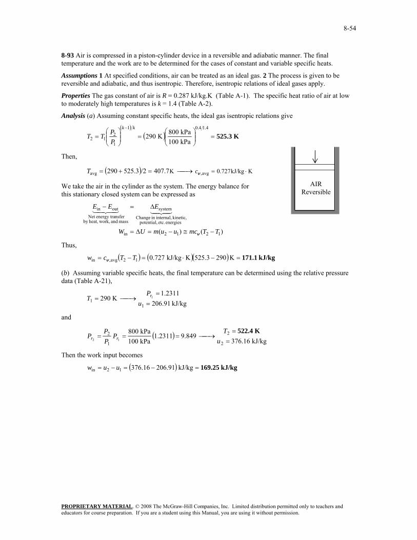
8-93 Air is compressed in a piston-cylinder device in a reversible and adiabatic manner. The final temperature and the work are to be determined for the cases of constant and variable specific heats.
Assumptions 1 At specified conditions, air can be treated as an ideal gas. 2 The process is given to be reversible and adiabatic, and thus isentropic. Therefore, isentropic relations of ideal gases apply.
Properties The gas constant of air is R = 0.287 kJ/kg.K (Table A-1). The specific heat ratio of air at low to moderately high temperatures is k = 1.4 (Table A-2).
Analysis (a) Assuming constant specific heats, the ideal gas isentropic relations give
8-94 EES Problem 8-93 is reconsidered. The work done and final temperature during the compression process are to be calculated and plotted as functions of the final pressure for the two cases as the final pressure varies from 100 kPa to 800 kPa.
Analysis The problem is solved using EES, and the results are tabulated and plotted below.
Procedure ConstPropSol(P_1,T_1,P_2,Gas$:Work_in_ConstProp,T2_ConstProp) C_P=SPECHEAT(Gas$,T=27) MM=MOLARMASS(Gas$) R_u=8.314 [kJ/kmol-K] R=R_u/MM C_V = C_P - R k = C_P/C_V T2= (T_1+273)*(P_2/P_1)^((k-1)/k) T2_ConstProp=T2-273 "[C]" DELTAu = C_v*(T2-(T_1+273)) Work_in_ConstProp = DELTAu End "Knowns:" P_1 = 100 [kPa] T_1 = 17 [C] P_2 = 800 [kPa] "Analysis: " " Treat the piston-cylinder as a closed system, with no heat transfer in, neglect changes in KE and PE of the air. The process is reversible and adiabatic thus isentropic." "The isentropic work is determined from:" e_in - e_out = DELTAe_sys e_out = 0 [kJ/kg] e_in = Work_in DELTAE_sys = (u_2 - u_1) u_1 = INTENERGY(air,T=T_1) v_1 = volume(air,P=P_1,T=T_1) s_1 = entropy(air,P=P_1,T=T_1) " The process is reversible and adiabatic or isentropic. Then P_2 and s_2 specify state 2." s_2 = s_1 u_2 = INTENERGY(air,P=P_2,s=s_2) T_2_isen=temperature(air,P=P_2,s=s_2) Gas$ = 'air' Call ConstPropSol(P_1,T_1,P_2,Gas$: Work_in_ConstProp,T2_ConstProp)
8-95 An insulated rigid tank contains argon gas at a specified pressure and temperature. A valve is opened, and argon escapes until the pressure drops to a specified value. The final mass in the tank is to be determined.
Assumptions 1 At specified conditions, argon can be treated as an ideal gas. 2 The process is given to be reversible and adiabatic, and thus isentropic. Therefore, isentropic relations of ideal gases apply.
Properties The specific heat ratio of argon is k = 1.667 (Table A-2).
Analysis From the ideal gas isentropic relations,
( )
( ) K 0.219kPa 450kPa 200K 303
1.6670.6671
1
212 =⎟⎟
⎠
⎞⎜⎜⎝
⎛=⎟⎟
⎠
⎞⎜⎜⎝
⎛=
− kk
PP
TT
The final mass in the tank is determined from the ideal gas relation,
8-96 EES Problem 8-95 is reconsidered. The effect of the final pressure on the final mass in the tank is to be investigated as the pressure varies from 450 kPa to 150 kPa, and the results are to be plotted.
Analysis The problem is solved using EES, and the results are tabulated and plotted below.
"Knowns:" C_P = 0.5203"[kJ/kg-K ]" C_V = 0.3122 "[kJ/kg-K ]" R=0.2081 "[kPa-m^3/kg-K]" P_1= 450"[kPa]" T_1 = 30"[C]" m_1 = 4"[kg]" P_2= 150"[kPa]" "Analysis: We assume the mass that stays in the tank undergoes an isentropic expansion process. This allows us to determine the final temperature of that gas at the final pressure in the tank by using the isentropic relation:" k = C_P/C_V T_2 = ((T_1+273)*(P_2/P_1)^((k-1)/k)-273)"[C]" V_2 = V_1 P_1*V_1=m_1*R*(T_1+273) P_2*V_2=m_2*R*(T_2+273)
8-97E Air is accelerated in an adiabatic nozzle. Disregarding irreversibilities, the exit velocity of air is to be determined.
Assumptions 1 Air is an ideal gas with variable specific heats. 2 The process is given to be reversible and adiabatic, and thus isentropic. Therefore, isentropic relations of ideal gases apply. 2 The nozzle operates steadily.
Analysis Assuming variable specific heats, the inlet and exit properties are determined to be
and
( )Btu/lbm 152.11
R 635.92.4612.30
psia 60psia 12
Btu/lbm 240.9830.12
R 1000
2
2
1
2
11
12
1
==
⎯→⎯===
==
⎯→⎯=
hT
PPPP
hP
T
rr
r
We take the nozzle as the system, which is a control volume. The energy balance for this steady-flow system can be expressed in the rate form as
02
/2)V+()2/(
0
21
22
12
222
211
outin
energies etc. potential, kinetic, internal,in change of Rate
8-98E Air is expanded in an isentropic turbine. The exit temperature of the air and the power produced are to be determined.
Assumptions 1 This is a steady-flow process since there is no change with time. 2 The process is isentropic (i.e., reversible-adiabatic). 3 Air is an ideal gas with constant specific heats.
Properties The properties of air at an anticipated average temperature of 600°F are cp = 0.250 Btu/lbm·R and k = 1.377 (Table A-2Eb). The gas constant of air is R = 0.3704 psia⋅ft3/lbm⋅R (Table A-1E).
Analysis There is only one inlet and one exit, and thus mmm &&& == 21 . We take the turbine as the system, which is a control volume since mass crosses the boundary. The energy balance for this steady-flow system can be expressed in the rate form as
outin
energies etc. potential, kinetic, internal,in change of Rate
(steady) 0system
mass and work,heat,by nsferenergy tranet of Rate
outin 0
EE
EEE
&&
444 344 21&
43421&&
=
=Δ=−
⎟⎟⎠
⎞⎜⎜⎝
⎛ −+−=
⎟⎟⎠
⎞⎜⎜⎝
⎛ −+−=
+⎟⎟⎠
⎞⎜⎜⎝
⎛+=⎟
⎟⎠
⎞⎜⎜⎝
⎛+
2)(
2
22
22
21
21
22
21
21out
out
22
2
21
1
VVTTcm
VVhhmW
WV
hmV
hm
p&
&&
&&&
The exit temperature of the air for this isentropic process is
R 724=⎟⎟⎠
⎞⎜⎜⎝
⎛+=⎟⎟
⎠
⎞⎜⎜⎝
⎛=
− 377.1/377.0/)1(
1
212 psia 150
psia 15R) 460(900kk
PP
TT
The specific volume of air at the inlet and the mass flow rate are
/lbmft 358.3psia 150
R) 460R)(900/lbmftpsia 3704.0( 33
1
11 =
+⋅⋅==
PRT
v
lbm/s 45.74/lbmft 3.358
ft/s) 500)(ft 5.0(3
2
1
11 ===v
VAm&
Substituting into the energy balance equation gives
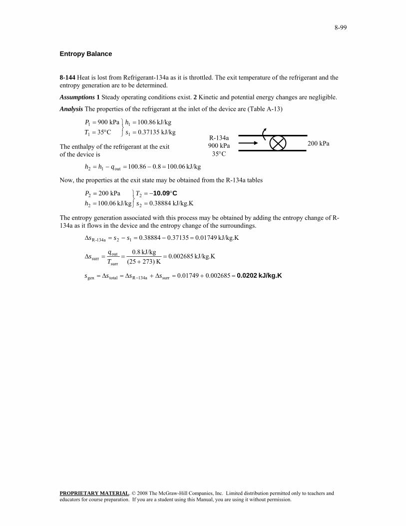
8-99 Nitrogen is compressed in an adiabatic compressor. The minimum work input is to be determined.
Assumptions 1 This is a steady-flow process since there is no change with time. 2 The process is adiabatic, and thus there is no heat transfer. 3 Nitrogen is an ideal gas with constant specific heats.
Properties The properties of nitrogen at an anticipated average temperature of 400 K are cp = 1.044 kJ/kg·K and k = 1.397 (Table A-2b).
Analysis There is only one inlet and one exit, and thus mmm &&& == 21 . We take the compressor as the system, which is a control volume since mass crosses the boundary. The energy balance for this steady-flow system can be expressed in the rate form as
outin
energies etc. potential, kinetic, internal,in change of Rate
(steady) 0system
mass and work,heat,by nsferenergy tranet of Rate
outin 0
EE
EEE
&&
444 344 21&
43421&&
=
=Δ=−
)( 12in
2in1
hhmW
hmWhm
−=
=+
&&
&&&
For the minimum work input to the compressor, the process must be reversible as well as adiabatic (i.e., isentropic). This being the case, the exit temperature will be
K 479kPa 120kPa 600K) (303
397.1/397.0/)1(
1
212 =⎟
⎠⎞
⎜⎝⎛=⎟⎟
⎠
⎞⎜⎜⎝
⎛=
− kk
PP
TT
Substituting into the energy balance equation gives
kJ/kg 184=−⋅=−=−= )K303K)(479kJ/kg 044.1()( 1212in TTchhw p
8-100 Oxygen is expanded in an adiabatic nozzle. The maximum velocity at the exit is to be determined.
Assumptions 1 This is a steady-flow process since there is no change with time. 2 The process is adiabatic, and thus there is no heat transfer. 3 Oxygen is an ideal gas with constant specific heats.
Properties The properties of oxygen at room temperature are cp = 0.918 kJ/kg·K and k = 1.395 (Table A-2a).
Analysis For the maximum velocity at the exit, the process must be reversible as well as adiabatic (i.e., isentropic). This being the case, the exit temperature will be
K 280.0kPa 300kPa 120K) (363
395.1/395.0/)1(
1
212 =⎟
⎠⎞
⎜⎝⎛=⎟⎟
⎠
⎞⎜⎜⎝
⎛=
− kk
PP
TT
There is only one inlet and one exit, and thus mmm &&& == 21 . We take nozzle as the system, which is a control volume since mass crosses the boundary. The energy balance for this steady-flow system can be expressed in the rate form as
outin
energies etc. potential, kinetic, internal,in change of Rate
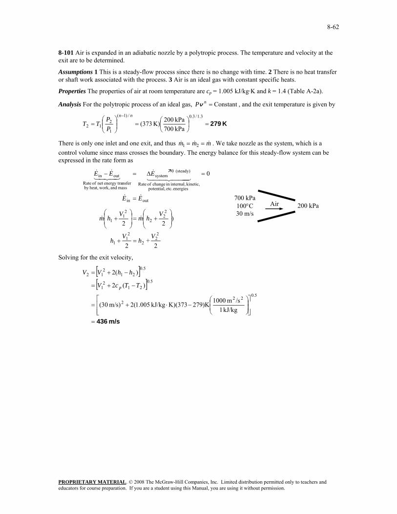
8-101 Air is expanded in an adiabatic nozzle by a polytropic process. The temperature and velocity at the exit are to be determined.
Assumptions 1 This is a steady-flow process since there is no change with time. 2 There is no heat transfer or shaft work associated with the process. 3 Air is an ideal gas with constant specific heats.
Properties The properties of air at room temperature are cp = 1.005 kJ/kg·K and k = 1.4 (Table A-2a).
Analysis For the polytropic process of an ideal gas, Constant=nPv , and the exit temperature is given by
K 279=⎟⎠⎞
⎜⎝⎛=⎟⎟
⎠
⎞⎜⎜⎝
⎛=
− 3.1/3.0/)1(
1
212 kPa 700
kPa 200K) (373nn
PP
TT
There is only one inlet and one exit, and thus mmm &&& == 21 . We take nozzle as the system, which is a control volume since mass crosses the boundary. The energy balance for this steady-flow system can be expressed in the rate form as
outin
energies etc. potential, kinetic, internal,in change of Rate
8-102 Air is expanded in an adiabatic nozzle by a polytropic process. The temperature and velocity at the exit are to be determined.
Assumptions 1 This is a steady-flow process since there is no change with time. 2 There is no heat transfer or shaft work associated with the process. 3 Air is an ideal gas with constant specific heats.
Properties The properties of air at room temperature are cp = 1.005 kJ/kg·K and k = 1.4 (Table A-2a).
Analysis For the polytropic process of an ideal gas, Constant=nPv , and the exit temperature is given by
K 303=⎟⎠⎞
⎜⎝⎛=⎟⎟
⎠
⎞⎜⎜⎝
⎛=
− 2.1/2.0/)1(
1
212 kPa 700
kPa 200K) (373nn
PP
TT
There is only one inlet and one exit, and thus mmm &&& == 21 . We take nozzle as the system, which is a control volume since mass crosses the boundary. The energy balance for this steady-flow system can be expressed in the rate form as
outin
energies etc. potential, kinetic, internal,in change of Rate
8-103E Air is charged to an initially evacuated container from a supply line. The minimum temperature of the air in the container after it is filled is to be determined.
Assumptions 1 This is an unsteady process since the conditions within the device are changing during the process, but it can be analyzed as a uniform-flow process since the state of fluid at the inlet remains constant. 2 Air is an ideal gas with constant specific heats. 3 Kinetic and potential energies are negligible. 4 There are no work interactions involved. 5 The tank is well-insulated, and thus there is no heat transfer.
Properties The specific heat of air at room temperature is cp = 0.240 Btu/lbm·R (Table A-2Ea).
Analysis We take the tank as the system, which is a control volume since mass crosses the boundary. Noting that the microscopic energies of flowing and nonflowing fluids are represented by enthalpy h and internal energy u, respectively, the mass and entropy balances for this uniform-flow system can be expressed as
Mass balance:
2
12
systemoutin
mmmmm
mmm
i
i
=−=
Δ=−
Entropy balance:
00
22
1122
≥−≥−+−
ii
iiee
smsmsmsmsmsm
Combining the two balances,
00
2
222
≥−≥−
i
i
sssmsm
The minimum temperature will result when the equal sign applies. Noting that P2 = Pi, we have
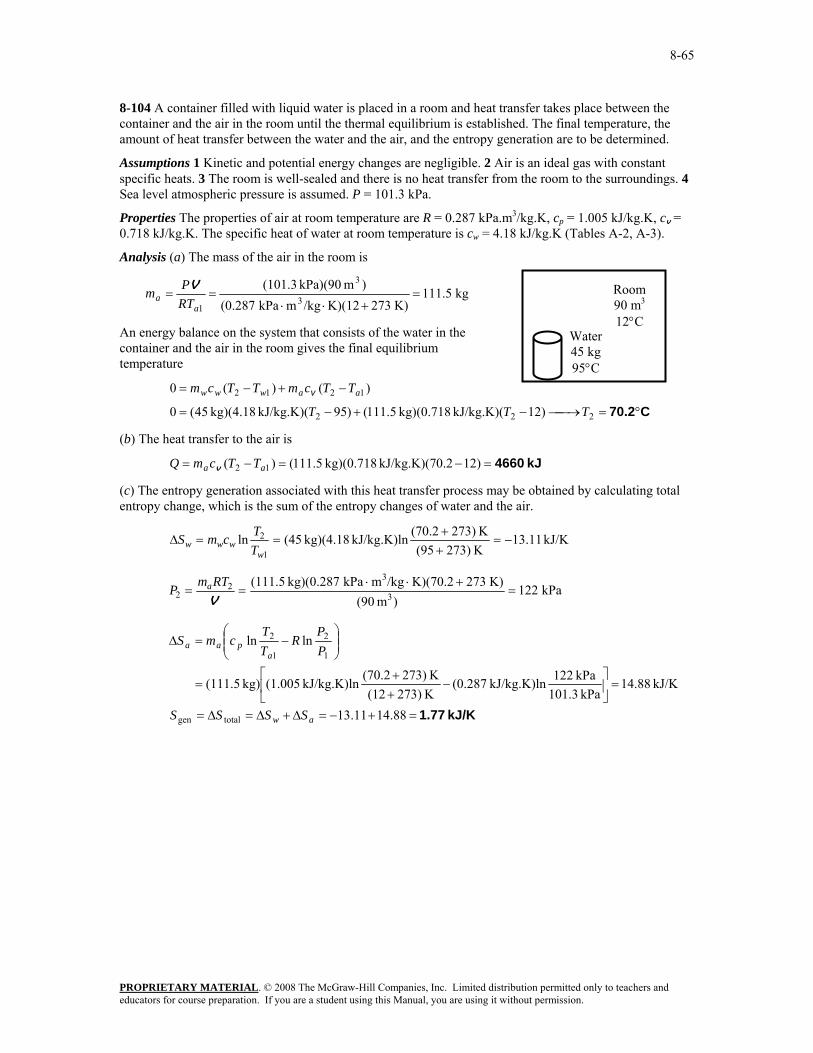
8-104 A container filled with liquid water is placed in a room and heat transfer takes place between the container and the air in the room until the thermal equilibrium is established. The final temperature, the amount of heat transfer between the water and the air, and the entropy generation are to be determined.
Assumptions 1 Kinetic and potential energy changes are negligible. 2 Air is an ideal gas with constant specific heats. 3 The room is well-sealed and there is no heat transfer from the room to the surroundings. 4 Sea level atmospheric pressure is assumed. P = 101.3 kPa.
Properties The properties of air at room temperature are R = 0.287 kPa.m3/kg.K, cp = 1.005 kJ/kg.K, cv = 0.718 kJ/kg.K. The specific heat of water at room temperature is cw = 4.18 kJ/kg.K (Tables A-2, A-3).
Analysis (a) The mass of the air in the room is
kg 5.111K) 273K)(12/kgmkPa (0.287
)m kPa)(90 (101.33
3
1=
+⋅⋅==
aa RT
Pm V
An energy balance on the system that consists of the water in the container and the air in the room gives the final equilibrium temperature
kJ 4660=−=−= )120.2kJ/kg.K)(7 kg)(0.718 5.111()( 12 aa TTcmQ v
(c) The entropy generation associated with this heat transfer process may be obtained by calculating total entropy change, which is the sum of the entropy changes of water and the air.
8-106 An ideal gas is compressed in an isentropic compressor. 10% of gas is compressed to 400 kPa and 90% is compressed to 600 kPa. The compression process is to be sketched, and the exit temperatures at the two exits, and the mass flow rate into the compressor are to be determined.
Assumptions 1 The compressor operates steadily. 2 The process is reversible-adiabatic (isentropic)
Properties The properties of ideal gas are given to be cp = 1.1 kJ/kg.K and cv = 0.8 kJ/kg.K.
Analysis (b) The specific heat ratio of the gas is
375.18.01.1===
vcc
k p
The exit temperatures are determined from ideal gas isentropic relations to be,
( ) K 437.8=⎟⎟⎠
⎞⎜⎜⎝
⎛+=⎟⎟
⎠
⎞⎜⎜⎝
⎛=
− 50.375/1.37/)1(
1
212 kPa 100
kPa 400K 27327
kk
PP
TT
( ) K 489.0=⎟⎟⎠
⎞⎜⎜⎝
⎛+=⎟⎟
⎠
⎞⎜⎜⎝
⎛=
− 50.375/1.37/)1(
1
313 kPa 100
kPa 600K 27327
kk
PP
TT
(c) A mass balance on the control volume gives
321 mmm &&& +=
where
13
12
9.01.0mmmm&&
&&
==
We take the compressor as the system, which is a control volume. The energy balance for this steady-flow system can be expressed in the rate form as
3121in11
3322in11
outin
energies etc. potential, kinetic, internal,in change of Rate
8-107 Air contained in a constant-volume tank s cooled to ambient temperature. The entropy changes of the air and the universe due to this process are to be determined and the process is to be sketched on a T-s diagram.
Assumptions 1 Air is an ideal gas with constant specific heats.
Properties The specific heat of air at room temperature is cv = 0.718 kJ/kg.K (Table A-2a).
Analysis (a) The entropy change of air is determined from
kJ/K 2.488−=++
=
=Δ
K 273)(327K 273)(27kJ/kg.K)ln kg)(0.718 (5
ln1
2air T
TmcS v
(b) An energy balance on the system gives
kJ 1077)2727kJ/kg.K)(3 kg)(0.718 5(
)( 21out
=−=
−= TTmcQ v
The entropy change of the surroundings is
kJ/K 3.59K 300kJ 1077
surr
outsurr ===Δ
TQs
The entropy change of universe due to this process is
8-108C The work associated with steady-flow devices is proportional to the specific volume of the gas. Cooling a gas during compression will reduce its specific volume, and thus the power consumed by the compressor.
8-109C Cooling the steam as it expands in a turbine will reduce its specific volume, and thus the work output of the turbine. Therefore, this is not a good proposal.
8-110C We would not support this proposal since the steady-flow work input to the pump is proportional to the specific volume of the liquid, and cooling will not affect the specific volume of a liquid significantly.
8-111 Air is compressed isothermally in a reversible steady-flow device. The work required is to be determined.
Assumptions 1 This is a steady-flow process since there is no change with time. 2 There is no heat transfer associated with the process. 3 Kinetic and potential energy changes are negligible. 4 Air is an ideal gas with constant specific heats.
Properties The gas constant of air is R = 0.06855 Btu/lbm·R (Table A-1E).
Analysis Substituting the ideal gas equation of state into the reversible steady-flow work expression gives
8-112 Saturated water vapor is compressed in a reversible steady-flow device. The work required is to be determined.
Assumptions 1 This is a steady-flow process since there is no change with time. 2 There is no heat transfer associated with the process. 3 Kinetic and potential energy changes are negligible.
Analysis The properties of water at the inlet state are
4)-A (Table/kgm 39248.0
kPa 16.476
1 C150
31
1
1
1 ==
⎭⎬⎫
=°=
v
PxT
Noting that the specific volume remains constant, the reversible steady-flow work expression gives
kJ/kg 205.6=
⎟⎠
⎞⎜⎝
⎛
⋅=
−== ∫
33
121
2
1in
mkPa 1kJ 1476.16)kPa-/kg)(1000m (0.39248
)( PPdPw vv
8-113 The work produced for the process 1-3 shown in the figure is to be determined.
Assumptions Kinetic and potential energy changes are negligible.
Analysis The work integral represents the area to the left of the reversible process line. Then,
8-114E The work produced for the process 1-2 shown in the figure is to be determined.
Assumptions Kinetic and potential energy changes are negligible.
Analysis The work integral represents the area to the left of the reversible process line. Then,
Btu/lbm 66.6=
⎟⎟⎠
⎞⎜⎜⎝
⎛
⋅−
+=
−+
=
= ∫
3
3
1221
2
12-in,1
ftpsia 5.404Btu 1psia)100500(
2/lbmft)7.11.0(
)(2
PP
dPw
vv
v
8-115 Liquid water is to be pumped by a 25-kW pump at a specified rate. The highest pressure the water can be pumped to is to be determined.
Assumptions 1 Liquid water is an incompressible substance. 2 Kinetic and potential energy changes are negligible. 3 The process is assumed to be reversible since we will determine the limiting case.
Properties The specific volume of liquid water is given to be v1 = 0.001 m3/kg.
Analysis The highest pressure the liquid can have at the pump exit can be determined from the reversible steady-flow work relation for a liquid,
8-116 A steam power plant operates between the pressure limits of 10 MPa and 20 kPa. The ratio of the turbine work to the pump work is to be determined.
Assumptions 1 Liquid water is an incompressible substance. 2 Kinetic and potential energy changes are negligible. 3 The process is reversible. 4 The pump and the turbine are adiabatic.
Properties The specific volume of saturated liquid water at 20 kPa is v1 = vf @ 20 kPa = 0.001017 m3/kg (Table A-5).
Analysis Both the compression and expansion processes are reversible and adiabatic, and thus isentropic,
s1 = s2 and s3 = s4. Then the properties of the steam are
kJ/kg 4707.2MPa 10
KkJ/kg 7.9073kJ/kg 2608.9
.kPa 20
343
3
kPa 20@4
kPa 20@44
=⎭⎬⎫
==
⋅====
⎭⎬⎫=
hss
P
sshh
vaporsatP
g
g
Also, v1 = vf @ 20 kPa = 0.001017 m3/kg.
The work output to this isentropic turbine is determined from the steady-flow energy balance to be
)(
0
43out
out43
outin
energies etc. potential, kinetic, internal,in change of Rate
(steady) 0system
mass and work,heat,by nsferenergy tranet of Rate
outin
hhmW
Whmhm
EE
EEE
−=
+=
=
=Δ=−
&&
&&&
&&
44 344 21&
43421&&
Substituting,
kJ/kg 2098.39.26082.470743outturb, =−=−= hhw
The pump work input is determined from the steady-flow work relation to be
8-117 EES Problem 8-116 is reconsidered. The effect of the quality of the steam at the turbine exit on the net work output is to be investigated as the quality is varied from 0.5 to 1.0, and the net work output us to be plotted as a function of this quality.
Analysis The problem is solved using EES, and the results are tabulated and plotted below.
"System: control volume for the pump and turbine" "Property relation: Steam functions" "Process: For Pump and Turbine: Steady state, steady flow, adiabatic, reversible or isentropic" "Since we don't know the mass, we write the conservation of energy per unit mass." "Conservation of mass: m_dot[1]= m_dot[2]" "Knowns:" WorkFluid$ = 'Steam_IAPWS' P[1] = 20 [kPa] x[1] = 0 P[2] = 10000 [kPa] x[4] = 1.0 "Pump Analysis:" T[1]=temperature(WorkFluid$,P=P[1],x=0) v[1]=volume(workFluid$,P=P[1],x=0) h[1]=enthalpy(WorkFluid$,P=P[1],x=0) s[1]=entropy(WorkFluid$,P=P[1],x=0) s[2] = s[1] h[2]=enthalpy(WorkFluid$,P=P[2],s=s[2]) T[2]=temperature(WorkFluid$,P=P[2],s=s[2]) "The Volume function has the same form for an ideal gas as for a real fluid." v[2]=volume(WorkFluid$,T=T[2],p=P[2]) "Conservation of Energy - SSSF energy balance for pump" " -- neglect the change in potential energy, no heat transfer:" h[1]+W_pump = h[2] "Also the work of pump can be obtained from the incompressible fluid, steady-flow result:" W_pump_incomp = v[1]*(P[2] - P[1]) "Conservation of Energy - SSSF energy balance for turbine -- neglecting the change in potential energy, no heat transfer:" P[4] = P[1] P[3] = P[2] h[4]=enthalpy(WorkFluid$,P=P[4],x=x[4]) s[4]=entropy(WorkFluid$,P=P[4],x=x[4]) T[4]=temperature(WorkFluid$,P=P[4],x=x[4]) s[3] = s[4] h[3]=enthalpy(WorkFluid$,P=P[3],s=s[3]) T[3]=temperature(WorkFluid$,P=P[3],s=s[3]) h[3] = h[4] + W_turb W_net_out = W_turb - W_pump
8-118 Liquid water is pumped by a 70-kW pump to a specified pressure at a specified level. The highest possible mass flow rate of water is to be determined.
Assumptions 1 Liquid water is an incompressible substance. 2 Kinetic energy changes are negligible, but potential energy changes may be significant. 3 The process is assumed to be reversible since we will determine the limiting case.
Properties The specific volume of liquid water is given to be v1 = 0.001 m3/kg.
Analysis The highest mass flow rate will be realized when the entire process is reversible. Thus it is determined from the reversible steady-flow work relation for a liquid,
8-119E Helium gas is compressed from a specified state to a specified pressure at a specified rate. The power input to the compressor is to be determined for the cases of isentropic, polytropic, isothermal, and two-stage compression.
Assumptions 1 Helium is an ideal gas with constant specific heats. 2 The process is reversible. 3 Kinetic and potential energy changes are negligible.
Properties The gas constant of helium is R = 2.6805 psia.ft3/lbm.R = 0.4961 Btu/lbm.R. The specific heat ratio of helium is k = 1.667 (Table A-2E).
(d) Ideal two-stage compression with intercooling (n = 1.2): In this case, the pressure ratio across each stage is the same, and its value is determined from
( )( ) psia 41.0psia 120psia 1421 === PPPx
The compressor work across each stage is also the same, thus total compressor work is twice the compression work for a single stage:
8-120E EES Problem 8-119E is reconsidered. The work of compression and entropy change of the helium is to be evaluated and plotted as functions of the polytropic exponent as it varies from 1 to 1.667.
Analysis The problem is solved using EES, and the results are tabulated and plotted below.
8-121 Water mist is to be sprayed into the air stream in the compressor to cool the air as the water evaporates and to reduce the compression power. The reduction in the exit temperature of the compressed air and the compressor power saved are to be determined.
Assumptions 1 Air is an ideal gas with variable specific heats. 2 The process is reversible. 3 Kinetic and potential energy changes are negligible. 3 Air is compressed isentropically. 4 Water vaporizes completely before leaving the compressor. 4 Air properties can be used for the air-vapor mixture.
Properties The gas constant of air is R = 0.287 kJ/kg.K (Table A-1). The specific heat ratio of air is k = 1.4. The inlet enthalpies of water and air are (Tables A-4 and A-17)
hw1 = hf@20°C = 83.29 kJ/kg , hfg@20°C = 2453.9 kJ/kg and ha1 = h@300 K =300.19 kJ/kg
Analysis In the case of isentropic operation (thus no cooling or water spray), the exit temperature and the power input to the compressor are
When water is sprayed, we first need to check the accuracy of the assumption that the water vaporizes completely in the compressor. In the limiting case, the compression will be isothermal at the compressor inlet temperature, and the water will be a saturated vapor. To avoid the complexity of dealing with two fluid streams and a gas mixture, we disregard water in the air stream (other than the mass flow rate), and assume air is cooled by an amount equal to the enthalpy change of water.
The rate of heat absorption of water as it evaporates at the inlet temperature completely is
This corresponds to maximum cooling from the air since, at constant temperature, Δh = 0 and thus kW 3.449inout ==WQ && , which is close to 490.8 kW. Therefore, the assumption that all the water vaporizes
is approximately valid. Then the reduction in required power input due to water spray becomes
Discussion (can be ignored): At constant temperature, Δh = 0 and thus kW 3.449== inout WQ && corresponds to maximum cooling from the air, which is less than 490.8 kW. Therefore, the assumption that all the water vaporizes is only roughly valid. As an alternative, we can assume the compression process to be polytropic and the water to be a saturated vapor at the compressor exit temperature, and disregard the remaining liquid. But in this case there is not a unique solution, and we will have to select either the amount of water or the exit temperature or the polytropic exponent to obtain a solution. Of course we can also tabulate the results for different cases, and then make a selection.
Sample Analysis: We take the compressor exit temperature to be T2 = 200°C = 473 K. Then,
hw2 = hg@200°C = 2792.0 kJ/kg and ha2 = h@473 K = 475.3 kJ/kg
Then,
224.1 kPa 100kPa 1200
K 300K 473
/)1(/)1(
1
2
1
2 =→⎟⎠⎞
⎜⎝⎛=→⎟⎟
⎠
⎞⎜⎜⎝
⎛=
−−
nPP
TT nnnn
( )( ){ }( )( )
kW 570K)300473(11.224
KkJ/kg 0.2871.224kg/s) 1.2(
)(1
11 12
/112
1,
=−−
⋅=
−−
=−−
= − TTnnRmPP
nnRT
mW nnincomp &&&
Energy balance:
kW 0.202300.19)3kg/s)(475. 1.2(kW 7.569
)( )( 12incomp,out12outincomp,
=−−=
−−=→−=− hhmWQhhmQW &&&&&&
Noting that this heat is absorbed by water, the rate at which water evaporates in the compressor becomes
kg/s 0746.0kJ/kg )29.830.2792(
kJ/s 0.202 )(12
waterin,12waterin,airout, =
−=
−=⎯→⎯−==
wwwwww hh
QmhhmQQ
&&&&&
Then the reductions in the exit temperature and compressor power input become
Δ
Δ
T T T
W W Wcomp in comp comp
2 2 2 610 2 473
654 3 570
= − = − = °
= − = − =
, ,
, , ,
.& & & .
isentropic water cooled
isentropic water cooled
137.2 C
84.3 kW
Note that selecting a different compressor exit temperature T2 will result in different values.
8-122 A water-injected compressor is used in a gas turbine power plant. It is claimed that the power output of a gas turbine will increase when water is injected into the compressor because of the increase in the mass flow rate of the gas (air + water vapor) through the turbine. This, however, is not necessarily right since the compressed air in this case enters the combustor at a low temperature, and thus it absorbs much more heat. In fact, the cooling effect will most likely dominate and cause the cyclic efficiency to drop.
8-123C The ideal process for all three devices is the reversible adiabatic (i.e., isentropic) process. The adiabatic efficiencies of these devices are defined as
energy kineticexit cinsentropi
energykineticexit actual and ,inputwork actual
inputwork cinsentropi ,outputwork cinsentropi
outputwork actual===
NCTηηη
8-124C No, because the isentropic process is not the model or ideal process for compressors that are cooled intentionally.
8-125C Yes. Because the entropy of the fluid must increase during an actual adiabatic process as a result of irreversibilities. Therefore, the actual exit state has to be on the right-hand side of the isentropic exit state
8-126 Saturated steam is compressed in an adiabatic process with an isentropic efficiency of 0.90. The work required is to be determined.
Assumptions 1 Kinetic and potential energy changes are negligible. 2 The device is adiabatic and thus heat transfer is negligible.
Analysis We take the steam as the system. This is a closed system since no mass enters or leaves. The energy balance for this stationary closed system can be expressed as
)( 12in
energies etc. potential, kinetic, internal,in Change
system
mass and work,heat,by nsferenergy traNet
outin
uumUW
EEE
−=Δ=
Δ=−4342143421
From the steam tables (Tables A-5 and A-6),
kJ/kg 0.2903MPa 1
KkJ/kg 3589.7kJ/kg 2505.6
vaporsat.kPa 100
212
2
kPa 100 @1
kPa 100 @11
=⎭⎬⎫
==
⋅====
⎭⎬⎫=
ss
g
g
uss
P
ssuuP
The work input during the isentropic process is
kJ 39,740kg2505.6)kJ/kg)(2903.0 100()( 12in, =−=−= uumW ss
8-127E R-134a is expanded in an adiabatic process with an isentropic efficiency of 0.95. The final volume is to be determined.
Assumptions 1 Kinetic and potential energy changes are negligible. 2 The device is adiabatic and thus heat transfer is negligible.
Analysis We take the R-134a as the system. This is a closed system since no mass enters or leaves. The energy balance for this stationary closed system can be expressed as
)( 12out
energies etc. potential, kinetic, internal,in Change
system
mass and work,heat,by nsferenergy traNet
outin
uumUW
EEE
−=Δ=−
Δ=−4342143421
From the R-134a tables (Tables A-11E through A-13E),
8-128 Steam is expanded in an adiabatic turbine with an isentropic efficiency of 0.92. The power output of the turbine is to be determined.
Assumptions 1 This is a steady-flow process since there is no change with time. 2 Kinetic and potential energy changes are negligible. 3 The device is adiabatic and thus heat transfer is negligible.
Analysis There is only one inlet and one exit, and thus mmm &&& == 21 . We take the actual turbine as the system, which is a control volume since mass crosses the boundary. The energy balance for this steady-flow system can be expressed in the rate form as
outin
energies etc. potential, kinetic, internal,in change of Rate
(steady) 0system
mass and work,heat,by nsferenergy tranet of Rate
outin 0
EE
EEE
&&
444 3444 21&
43421&&
=
=Δ=−
)(
0)ΔpeΔke (since
21out,
2out,1
hhmW
QhmWhm
a
a
−=
≅≅≅+=
&&
&&&&
From the steam tables (Tables A-4 through A-6),
kJ/kg 2335.7)3.2335)(8763.0(289.27
8763.08234.6
9441.09235.6
kPa 30
KkJ/kg 6.9235kJ/kg 3231.7
C004
MPa 3
22
22
12
2
1
1
1
1
=+=+=
=−
=−
=
⎭⎬⎫
==
⋅==
⎭⎬⎫
°==
fgsfs
fg
fss
s
s
hxhhs
ssx
ssP
sh
TP
The actual power output may be determined by multiplying the isentropic power output with the isentropic efficiency. Then,
8-129 Steam is expanded in an adiabatic turbine with an isentropic efficiency of 0.90. The power output of the turbine is to be determined.
Assumptions 1 This is a steady-flow process since there is no change with time. 2 Kinetic and potential energy changes are negligible. 3 The device is adiabatic and thus heat transfer is negligible.
Analysis There is only one inlet and one exit, and thus mmm &&& == 21 . We take the actual turbine as the system, which is a control volume since mass crosses the boundary. The energy balance for this steady-flow system can be expressed in the rate form as
outin
energies etc. potential, kinetic, internal,in change of Rate
(steady) 0system
mass and work,heat,by nsferenergy tranet of Rate
outin 0
EE
EEE
&&
444 3444 21&
43421&&
=
=Δ=−
)(
0)ΔpeΔke (since
21out,
2out,1
hhmW
QhmWhm
a
a
−=
≅≅≅+=
&&
&&&&
From the steam tables (Tables A-4 through A-6),
kJ/kg 2335.7)3.2335)(8763.0(289.27
8763.08234.6
9441.09235.6
kPa 30
KkJ/kg 6.9235kJ/kg 3231.7
C004
MPa 3
22
22
12
2
1
1
1
1
=+=+=
=−
=−
=
⎭⎬⎫
==
⋅==
⎭⎬⎫
°==
fgsfs
fg
fss
s
s
hxhhs
ssx
ssP
sh
TP
The actual power output may be determined by multiplying the isentropic power output with the isentropic efficiency. Then,
8-130 Argon gas is compressed by an adiabatic compressor. The isentropic efficiency of the compressor is to be determined.
Assumptions 1 This is a steady-flow process since there is no change with time. 2 Kinetic and potential energy changes are negligible. 3 The device is adiabatic and thus heat transfer is negligible. 4 Argon is an ideal gas with constant specific heats.
Properties The specific heat ratio of argon is k = 1.667 (Table A-2).
Analysis The isentropic exit temperature is
K8.753kPa 200kPa 2000) K300(
70.667/1.66/)1(
1
212 =⎟⎟
⎠
⎞⎜⎜⎝
⎛=⎟⎟
⎠
⎞⎜⎜⎝
⎛=
− kk
s PPTT
From the isentropic efficiency relation,
86.7%==−−
=
−−
=−
−=
−−
==
867.03008233008.753
)()(
12
12
12
12
12
12
TTTT
TTcTTc
hhhh
ww
a
s
ap
sp
a
s
a
sCη
8-131 R-134a is compressed by an adiabatic compressor. The isentropic efficiency of the compressor is to be determined.
Assumptions 1 This is a steady-flow process since there is no change with time. 2 Kinetic and potential energy changes are negligible. 3 The device is adiabatic and thus heat transfer is negligible.
Analysis From the R-134a tables (Tables A-11 through A-13),
8-132 Steam enters an adiabatic turbine at a specified state, and leaves at a specified state. The mass flow rate of the steam and the isentropic efficiency are to be determined.
Assumptions 1 This is a steady-flow process since there is no change with time. 2 Potential energy changes are negligible. 3 The device is adiabatic and thus heat transfer is negligible.
Analysis (a) From the steam tables (Tables A-4 and A-6),
kJ/kg 2780.2C150
kPa 50
KkJ/kg 7.0910kJ/kg 3650.6
C600MPa 7
22
2
1
1
1
1
=⎭⎬⎫
°==
⋅==
⎭⎬⎫
°==
ahTP
sh
TP
There is only one inlet and one exit, and thus & & &m m m1 2= = . We take the actual turbine as the system, which is a control volume since mass crosses the boundary. The energy balance for this steady-flow system can be expressed in the rate form as
outin
energies etc. potential, kinetic, internal,in change of Rate
(steady) 0system
mass and work,heat,by nsferenergy tranet of Rate
outin 0
EE
EEE
&&
44 344 21&
43421&&
=
=Δ=−
⎟⎟⎠
⎞⎜⎜⎝
⎛ −+−−=
≅Δ≅+=+
2
0)pe (since /2)+()2/(2
12
212outa,
212outa,
211
VVhhmW
QVhmWVhm
&&
&&&&
Substituting, the mass flow rate of the steam is determined to be
kg/s 6.95=
⎟⎟⎠
⎞⎜⎜⎝
⎛⎟⎠
⎞⎜⎝
⎛−+−−=
m
m
&
&22
22
/sm 1000kJ/kg 1
2)m/s 80()m/s 140(3650.62780.2kJ/s 6000
(b) The isentropic exit enthalpy of the steam and the power output of the isentropic turbine are
( )( ) kJ/kg 2467.32304.70.9228340.54
0.92286.5019
1.09127.0910kPa 50
22
22
12
2
=+=+=
=−
=−
=
⎭⎬⎫
==
fgsfs
fg
fss
s
s
hxhhs
ssx
ssP
and
( ){ }( )( )
kW 8174/sm 1000
kJ/kg 12
)m/s 80()m/s 140(3650.62467.3kg/s 6.95
2/
22
22
outs,
21
2212outs,
=
⎟⎟⎠
⎞⎜⎜⎝
⎛⎟⎠⎞
⎜⎝⎛−
+−−=
−+−−=
W
VVhhmW s
&
&&
Then the isentropic efficiency of the turbine becomes
8-133 Argon enters an adiabatic turbine at a specified state with a specified mass flow rate, and leaves at a specified pressure. The isentropic efficiency of the turbine is to be determined.
Assumptions 1 This is a steady-flow process since there is no change with time. 2 Kinetic and potential energy changes are negligible. 3 The device is adiabatic and thus heat transfer is negligible. 4 Argon is an ideal gas with constant specific heats.
Properties The specific heat ratio of argon is k = 1.667. The constant pressure specific heat of argon is cp = 0.5203 kJ/kg.K (Table A-2).
Analysis There is only one inlet and one exit, and thus & & &m m m1 2= = . We take the isentropic turbine as the system, which is a control volume since mass crosses the boundary. The energy balance for this steady-flow system can be expressed in the rate form as
)(
0)ΔpeΔke (since
21outs,
2out,1
outin
s
ss
hhmW
QhmWhm
EE
−=
≅≅≅+=
=
&&
&&&&
&&
From the isentropic relations,
( )
( ) K 479kPa 1500kPa 200K 1073
70.667/1.66/1
1
212 =⎟⎟
⎠
⎞⎜⎜⎝
⎛=⎟⎟
⎠
⎞⎜⎜⎝
⎛=
− kks
s PPTT
Then the power output of the isentropic turbine becomes
8-134E Combustion gases enter an adiabatic gas turbine with an isentropic efficiency of 82% at a specified state, and leave at a specified pressure. The work output of the turbine is to be determined.
Assumptions 1 This is a steady-flow process since there is no change with time. 2 Kinetic and potential energy changes are negligible. 3 The device is adiabatic and thus heat transfer is negligible. 4 Combustion gases can be treated as air that is an ideal gas with variable specific heats.
Analysis From the air table and isentropic relations,
Th
Pr1
1
1174 0
= ⎯ →⎯=
2000 R= 504.71 Btu / lbm
.
( ) Btu/lbm 417.387.0174.0psia 120psia 60
2s1
212
=⎯→⎯=⎟⎟⎠
⎞⎜⎜⎝
⎛=⎟⎟
⎠
⎞⎜⎜⎝
⎛= hP
PPP rr
There is only one inlet and one exit, and thus & & &m m m1 2= = . We take the actual turbine as the system, which is a control volume since mass crosses the boundary. The energy balance for this steady-flow system can be expressed as
)(
0)ΔpeΔke (since
21outa,
2outa,1
outin
hhmW
QhmWhm
EE
−=
≅≅≅+=
=
&&
&&&&
&&
Noting that wa = ηTws, the work output of the turbine per unit mass is determined from
8-135 CD EES Refrigerant-134a enters an adiabatic compressor with an isentropic efficiency of 0.80 at a specified state with a specified volume flow rate, and leaves at a specified pressure. The compressor exit temperature and power input to the compressor are to be determined.
Assumptions 1 This is a steady-flow process since there is no change with time. 2 Kinetic and potential energy changes are negligible. 3 The device is adiabatic and thus heat transfer is negligible.
Analysis (a) From the refrigerant tables (Tables A-11E through A-13E),
kJ/kg 281.21MPa 1
/kgm 0.16212KkJ/kg 0.94779
kJ/kg 236.97
vaporsat.kPa 120
212
2
3kPa 120@1
kPa 120@1
kPa 120@11
=⎭⎬⎫
==
==
⋅====
⎭⎬⎫=
ss
g
g
g
hss
P
sshh
P
vv
From the isentropic efficiency relation,
Thus,
( ) ( )
C58.9°=⎭⎬⎫
==
=−+=−+=⎯→⎯−−
=
aa
a
saa
s
ThP
hhhhhhhh
CC
22
2
121212
12
kJ/kg 292.26MPa 1
kJ/kg 292.26/0.80236.97281.21236.97/ηη
(b) The mass flow rate of the refrigerant is determined from
kg/s 0.0308/kgm 0.16212/sm 0.3/60
3
3
1
1 ===v
V&&m
There is only one inlet and one exit, and thus & & &m m m1 2= = . We take the actual compressor as the system, which is a control volume since mass crosses the boundary. The energy balance for this steady-flow system can be expressed as
outin
energies etc. potential, kinetic, internal,in change of Rate
(steady) 0system
mass and work,heat,by nsferenergy tranet of Rate
outin 0
EE
EEE
&&
44 344 21&
43421&&
=
=Δ=−
)(
0)ΔpeΔke (since
12ina,
21ina,
hhmW
QhmhmW
−=
≅≅≅=+
&&
&&&&
Substituting, the power input to the compressor becomes,
8-136 EES Problem 8-135 is reconsidered. The problem is to be solved by considering the kinetic energy and by assuming an inlet-to-exit area ratio of 1.5 for the compressor when the compressor exit pipe inside diameter is 2 cm.
Analysis The problem is solved using EES, and the solution is given below.
"Input Data from diagram window" {P[1] = 120 "kPa" P[2] = 1000 "kPa" Vol_dot_1 = 0.3 "m^3/min" Eta_c = 0.80 "Compressor adiabatic efficiency" A_ratio = 1.5 d_2 = 2/100 "m"} "System: Control volume containing the compressor, see the diagram window. Property Relation: Use the real fluid properties for R134a. Process: Steady-state, steady-flow, adiabatic process." Fluid$='R134a' "Property Data for state 1" T[1]=temperature(Fluid$,P=P[1],x=1)"Real fluid equ. at the sat. vapor state" h[1]=enthalpy(Fluid$, P=P[1], x=1)"Real fluid equ. at the sat. vapor state" s[1]=entropy(Fluid$, P=P[1], x=1)"Real fluid equ. at the sat. vapor state" v[1]=volume(Fluid$, P=P[1], x=1)"Real fluid equ. at the sat. vapor state" "Property Data for state 2" s_s[1]=s[1]; T_s[1]=T[1] "needed for plot" s_s[2]=s[1] "for the ideal, isentropic process across the compressor" h_s[2]=ENTHALPY(Fluid$, P=P[2], s=s_s[2])"Enthalpy 2 at the isentropic state 2s and pressure P[2]" T_s[2]=Temperature(Fluid$, P=P[2], s=s_s[2])"Temperature of ideal state - needed only for plot." "Steady-state, steady-flow conservation of mass" m_dot_1 = m_dot_2 m_dot_1 = Vol_dot_1/(v[1]*60) Vol_dot_1/v[1]=Vol_dot_2/v[2] Vel[2]=Vol_dot_2/(A[2]*60) A[2] = pi*(d_2)^2/4 A_ratio*Vel[1]/v[1] = Vel[2]/v[2] "Mass flow rate: = A*Vel/v, A_ratio = A[1]/A[2]" A_ratio=A[1]/A[2] "Steady-state, steady-flow conservation of energy, adiabatic compressor, see diagram window" m_dot_1*(h[1]+(Vel[1])^2/(2*1000)) + W_dot_c= m_dot_2*(h[2]+(Vel[2])^2/(2*1000)) "Definition of the compressor adiabatic efficiency, Eta_c=W_isen/W_act" Eta_c = (h_s[2]-h[1])/(h[2]-h[1]) "Knowing h[2], the other properties at state 2 can be found." v[2]=volume(Fluid$, P=P[2], h=h[2])"v[2] is found at the actual state 2, knowing P and h." T[2]=temperature(Fluid$, P=P[2],h=h[2])"Real fluid equ. for T at the known outlet h and P." s[2]=entropy(Fluid$, P=P[2], h=h[2]) "Real fluid equ. at the known outlet h and P." T_exit=T[2] "Neglecting the kinetic energies, the work is:" m_dot_1*h[1] + W_dot_c_noke= m_dot_2*h[2]
8-137 Air enters an adiabatic compressor with an isentropic efficiency of 84% at a specified state, and leaves at a specified temperature. The exit pressure of air and the power input to the compressor are to be determined.
Assumptions 1 This is a steady-flow process since there is no change with time. 2 Kinetic and potential energy changes are negligible. 3 The device is adiabatic and thus heat transfer is negligible. 4 Air is an ideal gas with variable specific heats.
Properties The gas constant of air is R = 0.287 kPa.m3/kg.K (Table A-1)
Analysis (a) From the air table (Table A-21),
kJ/kg 533.98K 530
1.2311kJ/kg, 290.16K 290
22
111
=⎯→⎯=
==⎯→⎯=
a
r
hT
PhT
From the isentropic efficiency relation 12
12
hhhh
a
sC −
−=η ,
( )( )( ) 951.7kJ/kg 495.0290.16533.980.84290.16
2
1212
=⎯→⎯=−+=
−+=
r
as
P
hhhhC
η
Then from the isentropic relation ,
( ) kPa646 kPa 1001.23117.951
121
2
1
2
1
2 =⎟⎠⎞
⎜⎝⎛=⎟
⎟⎠
⎞⎜⎜⎝
⎛=⎯→⎯= P
PP
PPP
PP
r
r
r
r
(b) There is only one inlet and one exit, and thus & & &m m m1 2= = . We take the actual compressor as the system, which is a control volume since mass crosses the boundary. The energy balance for this steady-flow system can be expressed as
outin
energies etc. potential, kinetic, internal,in change of Rate
(steady) 0system
mass and work,heat,by nsferenergy tranet of Rate
outin 0
EE
EEE
&&
44 344 21&
43421&&
=
=Δ=−
)(
0)ΔpeΔke (since
12ina,
21ina,
hhmW
QhmhmW
−=
≅≅≅=+
&&
&&&&
where
kg/s 884.2)K 290)(K/kgmkPa 0.287(
)/sm 2.4)(kPa 100(3
3
1
11 =⋅⋅
==RTP
mV&
&
Then the power input to the compressor is determined to be
8-138 Air is compressed by an adiabatic compressor from a specified state to another specified state. The isentropic efficiency of the compressor and the exit temperature of air for the isentropic case are to be determined.
Assumptions 1 This is a steady-flow process since there is no change with time. 2 Kinetic and potential energy changes are negligible. 3 The device is adiabatic and thus heat transfer is negligible. 4 Air is an ideal gas with variable specific heats.
Analysis (a) From the air table (Table A-21),
T h P
T h
r
a
1 1
2 2
11 386= ⎯ →⎯ = =
= ⎯ →⎯ =
300 K 300.19 kJ / kg,
550 K 554.74 kJ / kg
.
From the isentropic relation,
( ) kJ/kg 508.728.7541.386kPa 95kPa 600
21
212
=⎯→⎯=⎟⎟⎠
⎞⎜⎜⎝
⎛=⎟⎟
⎠
⎞⎜⎜⎝
⎛= srr hP
PPP
Then the isentropic efficiency becomes
ηC
h hh h
s
a=
−−
=−−
= =2 1
2 1
508 72 30019554 74 30019
0 819. .. .
. 81.9%
(b) If the process were isentropic, the exit temperature would be
8-139E Argon enters an adiabatic compressor with an isentropic efficiency of 80% at a specified state, and leaves at a specified pressure. The exit temperature of argon and the work input to the compressor are to be determined.
Assumptions 1 This is a steady-flow process since there is no change with time. 2 Potential energy changes are negligible. 3 The device is adiabatic and thus heat transfer is negligible. 4 Argon is an ideal gas with constant specific heats.
Properties The specific heat ratio of argon is k = 1.667. The constant pressure specific heat of argon is cp = 0.1253 Btu/lbm.R (Table A-2E).
Analysis (a) The isentropic exit temperature T2s is determined from
( )
( ) R 1381.9psia 20psia 200R 550
70.667/1.66/1
1
212 =⎟⎟
⎠
⎞⎜⎜⎝
⎛=⎟⎟
⎠
⎞⎜⎜⎝
⎛=
− kks
s PPTT
The actual kinetic energy change during this process is
( ) ( )
Btu/lbm 1.08/sft 25,037
Btu/lbm 12
ft/s 60ft/s 2402 22
2221
22 =⎟
⎟⎠
⎞⎜⎜⎝
⎛−=
−=Δ
VVkea
The effect of kinetic energy on isentropic efficiency is very small. Therefore, we can take the kinetic energy changes for the actual and isentropic cases to be same in efficiency calculations. From the isentropic efficiency relation, including the effect of kinetic energy,
( )( )
( )( ) 08.15501253.0
08.15509.13811253.08.0)()(
212
12
12
12
+−+−
=⎯→⎯Δ+−
Δ+−=
Δ+−Δ+−
==aaap
ssp
a
s
a
s
TkeTTckeTTc
kehhkehh
ww
Cη
It yields
T2a = 1592 R
(b) There is only one inlet and one exit, and thus & & &m m m1 2= = . We take the actual compressor as the system, which is a control volume since mass crosses the boundary. The energy balance for this steady-flow system can be expressed as
outin
energies etc. potential, kinetic, internal,in change of Rate
(steady) 0system
mass and work,heat,by nsferenergy tranet of Rate
outin 0
EE
EEE
&&
44 344 21&
43421&&
=
=Δ=−
Δke
2
0)pe (since /2)+()2/(
12ina,
21
22
12ina,
222
211ina,
+−=⎯→⎯⎟⎟⎠
⎞⎜⎜⎝
⎛ −+−=
≅Δ≅=++
hhwhhmW
QVhmVhmW
VV&&
&&&&
Substituting, the work input to the compressor is determined to be
8-140E Air is accelerated in a 90% efficient adiabatic nozzle from low velocity to a specified velocity. The exit temperature and pressure of the air are to be determined.
Assumptions 1 This is a steady-flow process since there is no change with time. 2 Potential energy changes are negligible. 3 The device is adiabatic and thus heat transfer is negligible. 4 Air is an ideal gas with variable specific heats.
Analysis From the air table (Table A-21E),
T h Pr1 1 153 04= ⎯ →⎯ = =1480 R 363.89 Btu / lbm, .
There is only one inlet and one exit, and thus & & &m m m1 2= = . We take the nozzle as the system, which is a control volume since mass crosses the boundary. The energy balance for this steady-flow system can be expressed as
outin
energies etc. potential, kinetic, internal,in change of Rate
(steady) 0system
mass and work,heat,by nsferenergy tranet of Rate
outin 0
EE
EEE
&&
44 344 21&
43421&&
=
=Δ=−
2
0)pe (since /2)+()2/(02
12
212
222
211
VVhh
QWVhmVhm
−−=
≅Δ≅==+ &&&&
Substituting, the exit temperature of air is determined to be
8-141E EES Problem 8-140E is reconsidered. The effect of varying the nozzle isentropic efficiency from 0.8 to 1.0 on the exit temperature and pressure of the air is to be investigated, and the results are to be plotted.
Analysis The problem is solved using EES, and the results are tabulated and plotted below.
8-142 Air is expanded in an adiabatic nozzle with an isentropic efficiency of 0.96. The air velocity at the exit is to be determined.
Assumptions 1 This is a steady-flow process since there is no change with time. 2 There is no heat transfer or shaft work associated with the process. 3 Air is an ideal gas with constant specific heats.
Properties The properties of air at room temperature are cp = 1.005 kJ/kg·K and k = 1.4 (Table A-2a).
Analysis For the isentropic process of an ideal gas, the exit temperature is determined from
K 331.0kPa 300kPa 100K) 273(180
4.1/4.0/)1(
1
212 =⎟
⎠⎞
⎜⎝⎛+=⎟⎟
⎠
⎞⎜⎜⎝
⎛=
− kk
s PP
TT
There is only one inlet and one exit, and thus mmm &&& == 21 . We take nozzle as the system, which is a control volume since mass crosses the boundary. The energy balance for this steady-flow system can be expressed in the rate form as
outin
energies etc. potential, kinetic, internal,in change of Rate
(steady) 0system
mass and work,heat,by nsferenergy tranet of Rate
outin 0
EE
EEE
&&
444 344 21&
43421&&
=
=Δ=−
ke2
)(
2
22
22
21
22
21
21
22
21
22
2
21
1
22
2
21
1
Δ=−
=−
−=−
+=+
⎟⎟⎠
⎞⎜⎜⎝
⎛+=⎟
⎟⎠
⎞⎜⎜⎝
⎛+
VVTTc
VVhh
Vh
Vh
Vhm
Vhm
p
&&
The kinetic energy change for the isentropic case is
8-143E Air is decelerated in an adiabatic diffuser with an isentropic efficiency of 0.82. The air velocity at the exit is to be determined.
Assumptions 1 This is a steady-flow process since there is no change with time. 2 There is no heat transfer or shaft work associated with the process. 3 Air is an ideal gas with constant specific heats.
Properties The properties of air at room temperature are cp = 0.240 Btu/lbm·R and k = 1.4 (Table A-2Ea).
Analysis For the isentropic process of an ideal gas, the exit temperature is determined from
R 2.554psia 13psia 20R) 460(30
4.1/4.0/)1(
1
212 =⎟⎟
⎠
⎞⎜⎜⎝
⎛+=⎟⎟
⎠
⎞⎜⎜⎝
⎛=
− kk
s PP
TT
There is only one inlet and one exit, and thus mmm &&& == 21 . We take nozzle as the system, which is a control volume since mass crosses the boundary. The energy balance for this steady-flow system can be expressed in the rate form as
outin
energies etc. potential, kinetic, internal,in change of Rate
(steady) 0system
mass and work,heat,by nsferenergy tranet of Rate
outin 0
EE
EEE
&&
444 344 21&
43421&&
=
=Δ=−
ke2
)(
2
22
22
21
22
21
21
22
21
22
2
21
1
22
2
21
1
Δ=−
=−
−=−
+=+
⎟⎟⎠
⎞⎜⎜⎝
⎛+=⎟
⎟⎠
⎞⎜⎜⎝
⎛+
VVTTc
VVhh
Vh
Vh
Vhm
Vhm
p
&&
The kinetic energy change for the isentropic case is
8-144 Heat is lost from Refrigerant-134a as it is throttled. The exit temperature of the refrigerant and the entropy generation are to be determined.
Assumptions 1 Steady operating conditions exist. 2 Kinetic and potential energy changes are negligible.
Analysis The properties of the refrigerant at the inlet of the device are (Table A-13)
kJ/kg 37135.0
kJ/kg 86.100C35kPa 090
1
1
1
1
==
⎭⎬⎫
°==
sh
TP
The enthalpy of the refrigerant at the exit of the device is
kJ/kg 06.1008.086.100out12 =−=−= qhh
Now, the properties at the exit state may be obtained from the R-134a tables
kJ/kg.K 38884.0kJ/kg 06.100
kPa 020
2
2
2
2
=°−=
⎭⎬⎫
==
sT
hP C10.09
The entropy generation associated with this process may be obtained by adding the entropy change of R-134a as it flows in the device and the entropy change of the surroundings.
8-145 Liquid water is withdrawn from a rigid tank that initially contains saturated water mixture until no liquid is left in the tank. The quality of steam in the tank at the initial state, the amount of mass that has escaped, and the entropy generation during this process are to be determined. Assumptions 1 Kinetic and potential energy changes are zero. 2 There are no work interactions. Analysis (a) The properties of the steam in the tank at the final state and the properties of exiting steam are (Tables A-4 through A-6)
kJ/kg.K 7765.1kJ/kg 66.604
liq.) (sat. 0kPa 400
kJ/kg.K 8955.6/kgm 46242.0
kJ/kg 1.2553
vap.)(sat. 1kPa 400
2
2
32
2
2
2
==
⎭⎬⎫
==
===
⎭⎬⎫
==
e
e
e
e
sh
xP
s
u
xP
v
The relations for the volume of the tank and the final mass in the tank are
131
22
111
219.16/kgm 0.46242
kg) 5.7(kg) 5.7(
vv
vV
vvV
===
==
m
m
The mass, energy, and entropy balances may be written as
Eq. (2) may be solved by a trial-error approach by trying different qualities at the inlet state. Or, we can use EES to solve the equations to find x1 = 0.8666 Other properties at the initial state are
kJ/kg.K 2129.6
/kgm 40089.0kJ/kg 2.2293
8666.0kPa 400
1
31
1
1
1
===
⎭⎬⎫
==
s
u
xP
v
Substituting into Eqs (1) and (3), (b) kg 0.998=−= )40089.0(219.165.7em
(c)
[ ]kJ/K 0.00553=
−=+−−+
gen
gen )2129.6(5.7)8955.6)(40089.0(219.16)7765.1()40089.0(219.165.7273500
8-146 Each member of a family of four take a 5-min shower every day. The amount of entropy generated by this family per year is to be determined.
Assumptions 1 Steady operating conditions exist. 2 The kinetic and potential energies are negligible. 3 Heat losses from the pipes and the mixing section are negligible and thus & .Q ≅ 0 4 Showers operate at maximum flow conditions during the entire shower. 5 Each member of the household takes a 5-min shower every day. 6 Water is an incompressible substance with constant properties at room temperature. 7 The efficiency of the electric water heater is 100%.
Properties The density and specific heat of water at room temperature are ρ = 1 kg/L and c = 4.18 kJ/kg.°C (Table A-3).
Analysis The mass flow rate of water at the shower head is
kg/min 12=L/min) kg/L)(12 (1== V&& ρm
The mass balance for the mixing chamber can be expressed in the rate form as
0
321outin
(steady) 0systemoutin
mmmmm
mmm
&&&&&
&&&
=+⎯→⎯=
=Δ=−
where the subscript 1 denotes the cold water stream, 2 the hot water stream, and 3 the mixture.
The rate of entropy generation during this process can be determined by applying the rate form of the entropy balance on a system that includes the electric water heater and the mixing chamber (the T-elbow). Noting that there is no entropy transfer associated with work transfer (electricity) and there is no heat transfer, the entropy balance for this steady-flow system can be expressed as
{
221133gen
gen332211
entropy of change of Rate
(steady) 0system
generation entropy of Rate
gen
mass andheat by ansferentropy trnet of Rate
outin
free)entropy is work and 0 (since 0
smsmsmS
QSsmsmsm
SSSS
&&&&
&&&&
44 344 21&&
43421&&
−−=
==+−+
Δ=+−
Noting from mass balance that & & &m m m1 2 3+ = and s2 = s1 since hot water enters the system at the same temperature as the cold water, the rate of entropy generation is determined to be
Discussion The value above represents the entropy generated within the water heater and the T-elbow in the absence of any heat losses. It does not include the entropy generated as the shower water at 42°C is discarded or cooled to the outdoor temperature. Also, an entropy balance on the mixing chamber alone (hot water entering at 55°C instead of 15°C) will exclude the entropy generated within the water heater.
8-147 Steam is condensed by cooling water in the condenser of a power plant. The rate of condensation of steam and the rate of entropy generation are to be determined.
Assumptions 1 Steady operating conditions exist. 2 The heat exchanger is well-insulated so that heat loss to the surroundings is negligible and thus heat transfer from the hot fluid is equal to the heat transfer to the cold fluid. 3 Changes in the kinetic and potential energies of fluid streams are negligible. 4 Fluid properties are constant.
Properties The enthalpy and entropy of vaporization of water at 60°C are hfg =2357.7 kJ/kg and sfg = 7.0769 kJ/kg.K (Table A-4). The specific heat of water at room temperature is cp = 4.18 kJ/kg.°C (Table A-3).
Analysis (a) We take the cold water tubes as the system, which is a control volume. The energy balance for this steady-flow system can be expressed in the rate form as
)(
0)peke (since
0
12in
21in
outin
energies etc. potential, kinetic, internal,in change of Rate
(steady) 0system
mass and work,heat,by nsferenergy tranet of Rate
outin
TTcmQ
hmhmQ
EE
EEE
p −=
≅Δ≅Δ=+
=
=Δ=−
&&
&&&
&&
44 344 21&
43421&&
Then the heat transfer rate to the cooling water in the condenser becomes
kJ/s 2822=C)18CC)(27kJ/kg. kg/s)(4.18 (75
)]([ watercoolinginout
°−°°=
−= TTcmQ p&&
The rate of condensation of steam is determined to be
(b) The rate of entropy generation within the condenser during this process can be determined by applying the rate form of the entropy balance on the entire condenser. Noting that the condenser is well-insulated and thus heat transfer is negligible, the entropy balance for this steady-flow system can be expressed as
{
)()(
0
)0 (since 0
34steam12watergen
gen4steam2water3steam1water
gen44223311
entropy of change of Rate
(steady) 0system
generation entropy of Rate
gen
mass andheat by ansferentropy trnet of Rate
outin
ssmssmS
Ssmsmsmsm
QSsmsmsmsm
SSSS
−+−=
=+−−+
==+−−+
Δ=+−
&&&
&&&&&
&&&&&
44 344 21&&
43421&&
Noting that water is an incompressible substance and steam changes from saturated vapor to saturated liquid, the rate of entropy generation is determined to be
8-148 Cold water is heated by hot water in a heat exchanger. The rate of heat transfer and the rate of entropy generation within the heat exchanger are to be determined.
Assumptions 1 Steady operating conditions exist. 2 The heat exchanger is well-insulated so that heat loss to the surroundings is negligible and thus heat transfer from the hot fluid is equal to the heat transfer to the cold fluid. 3 Changes in the kinetic and potential energies of fluid streams are negligible. 4 Fluid properties are constant.
Properties The specific heats of cold and hot water are given to be 4.18 and 4.19 kJ/kg.°C, respectively.
Analysis We take the cold water tubes as the system, which is a control volume. The energy balance for this steady-flow system can be expressed in the rate form as
)(
0)peke (since
0
12in
21in
outin
energies etc. potential, kinetic, internal,in change of Rate
(steady) 0system
mass and work,heat,by nsferenergy tranet of Rate
outin
TTcmQ
hmhmQ
EE
EEE
p −=
≅Δ≅Δ=+
=
=Δ=−
&&
&&&
&&
44 344 21&
43421&&
Then the rate of heat transfer to the cold water in this heat exchanger becomes
Noting that heat gain by the cold water is equal to the heat loss by the hot water, the outlet temperature of the hot water is determined to be
C97.5C)kJ/kg. kg/s)(4.19 3(
kW 35.31C100)]([ inouthot wateroutin °=°
−°=−=⎯→⎯−=p
p cmQTTTTcmQ&
&&&
(b) The rate of entropy generation within the heat exchanger is determined by applying the rate form of the entropy balance on the entire heat exchanger:
{
)()(
0
)0 (since 0
34hot12coldgen
gen4hot2cold3hot1cold
gen43223311
entropy of change of Rate
(steady) 0system
generation entropy of Rate
gen
mass andheat by ansferentropy trnet of Rate
outin
ssmssmS
Ssmsmsmsm
QSsmsmsmsm
SSSS
−+−=
=+−−+
==+−−+
Δ=+−
&&&
&&&&&
&&&&&
44 344 21&&
43421&&
Noting that both fluid streams are liquids (incompressible substances), the rate of entropy generation is determined to be
8-149 Air is preheated by hot exhaust gases in a cross-flow heat exchanger. The rate of heat transfer, the outlet temperature of the air, and the rate of entropy generation are to be determined.
Assumptions 1 Steady operating conditions exist. 2 The heat exchanger is well-insulated so that heat loss to the surroundings is negligible and thus heat transfer from the hot fluid is equal to the heat transfer to the cold fluid. 3 Changes in the kinetic and potential energies of fluid streams are negligible. 4 Fluid properties are constant.
Properties The specific heats of air and combustion gases are given to be 1.005 and 1.10 kJ/kg.°C, respectively. The gas constant of air is R = 0.287 kJ/kg.K (Table A-1).
Analysis We take the exhaust pipes as the system, which is a control volume. The energy balance for this steady-flow system can be expressed in the rate form as
)(
0)peke (since
0
21out
2out1
outin
energies etc. potential, kinetic, internal,in change of Rate
(steady) 0system
mass and work,heat,by nsferenergy tranet of Rate
outin
TTcmQ
hmQhm
EE
EEE
p −=
≅Δ≅Δ+=
=
=Δ=−
&&
&&&
&&
44 344 21&
43421&&
Then the rate of heat transfer from the exhaust gases becomes
8-150 Water is heated by hot oil in a heat exchanger. The outlet temperature of the oil and the rate of entropy generation within the heat exchanger are to be determined.
Assumptions 1 Steady operating conditions exist. 2 The heat exchanger is well-insulated so that heat loss to the surroundings is negligible and thus heat transfer from the hot fluid is equal to the heat transfer to the cold fluid. 3 Changes in the kinetic and potential energies of fluid streams are negligible. 4 Fluid properties are constant.
Properties The specific heats of water and oil are given to be 4.18 and 2.3 kJ/kg.°C, respectively.
Analysis (a) We take the cold water tubes as the system, which is a control volume. The energy balance for this steady-flow system can be expressed in the rate form as
)(
0)peke (since
0
12in
21in
outin
energies etc. potential, kinetic, internal,in change of Rate
(steady) 0system
mass and work,heat,by nsferenergy tranet of Rate
outin
TTcmQ
hmhmQ
EE
EEE
p −=
≅Δ≅Δ=+
=
=Δ=−
&&
&&&
&&
44 344 21&
43421&&
Then the rate of heat transfer to the cold water in this heat exchanger becomes
Noting that heat gain by the water is equal to the heat loss by the oil, the outlet temperature of the hot oil is determined from
C129.1°=°
−°=−=→−=C)kJ/kg. kg/s)(2.3 10(
kW 5.940C170 )]([ inoutoiloutinp
p cmQTTTTcmQ&
&&&
(b) The rate of entropy generation within the heat exchanger is determined by applying the rate form of the entropy balance on the entire heat exchanger:
{
)()(
0
)0 (since 0
34oil12watergen
gen4oil2water3oil1water
gen43223311
entropy of change of Rate
(steady) 0system
generation entropy of Rate
gen
mass andheat by ansferentropy trnet of Rate
outin
ssmssmS
Ssmsmsmsm
QSsmsmsmsm
SSSS
−+−=
=+−−+
==+−−+
Δ=+−
&&&
&&&&&
&&&&&
44 344 21&&
43421&&
Noting that both fluid streams are liquids (incompressible substances), the rate of entropy generation is determined to be
8-151E Refrigerant-134a is expanded adiabatically from a specified state to another. The entropy generation is to be determined.
Assumptions 1 Steady operating conditions exist. 2 Kinetic and potential energy changes are negligible.
Analysis The rate of entropy generation within the expansion device during this process can be determined by applying the rate form of the entropy balance on the system. Noting that the system is adiabatic and thus there is no heat transfer, the entropy balance for this steady-flow system can be expressed as
{
12gen
12gen
gen2211
entropy of change of Rate
(steady) 0system
generation entropy of Rate
gen
mass andheat by ansferentropy trnet of Rate
outin
)(
0
sss
ssmS
Ssmsm
SSSS
−=
−=
=+−
Δ=+−
&&
&&&
44 344 21&&
43421&&
The properties of the refrigerant at the inlet and exit states are (Tables A-11E through A-13E)
8-152 In an ice-making plant, water is frozen by evaporating saturated R-134a liquid. The rate of entropy generation is to be determined.
Assumptions 1 Steady operating conditions exist. 2 Kinetic and potential energy changes are negligible.
Analysis We take the control volume formed by the R-134a evaporator with a single inlet and single exit as the system. The rate of entropy generation within this evaporator during this process can be determined by applying the rate form of the entropy balance on the system. The entropy balance for this steady-flow system can be expressed as
{
wfgR
wR
w
TQ
smS
TQ
ssmS
STQ
smsm
SSSS
ingen
in12gen
genin
2211
entropy of change of Rate
(steady) 0system
generation entropy of Rate
gen
mass andheat by ansferentropy trnet of Rate
outin
)(
0
&&&
&&&
&&
&&
44 344 21&&
43421&&
−=
−−=
=++−
Δ=+−
The properties of the refrigerant are (Table A-11)
KkJ/kg 78263.0
kJ/kg 96.205
C10 @
C10 @
⋅=
=
°−
°−
fg
fg
s
h
The rate of that must be removed from the water in order to freeze it at a rate of 4000 kg/h is
8-153 Air is heated by steam in a heat exchanger. The rate of entropy generation associated with this process is to be determined.
Assumptions 1 Steady operating conditions exist. 2 The heat exchanger is well-insulated so that heat loss to the surroundings is negligible and thus heat transfer from the hot fluid is equal to the heat transfer to the cold fluid. 3 Changes in the kinetic and potential energies of fluid streams are negligible. 4 Air is an ideal gas with constant specific heats.
Properties The specific heat of air at room temperature is cp = 1.005 kJ/kg⋅°C (Table A-2).
Analysis The rate of entropy generation within the heat exchanger is determined by applying the rate form of the entropy balance on the entire heat exchanger:
{
)()(
0
34air12watergen
gen4air2water3air1water
entropy of change of Rate
(steady) 0system
generation entropy of Rate
gen
mass andheat by ansferentropy trnet of Rate
outin
ssmssmS
Ssmsmsmsm
SSSS
−+−=
=+−−+
Δ=+−
&&&
&&&&&
44 344 21&&
43421&&
The properties of the steam at the inlet and exit states are
KkJ/kg 3517.8
kJ/kg 6.2564
1 C35
1
1
1
1
⋅==
⎭⎬⎫
=°=
sh
xT
(Table A-4)
KkJ/kg 4641.0
kJ/kg 10.134
0 C32
2
2
2
2
⋅==
⎭⎬⎫
=°=
sh
xT
(Table A-4)
From an energy balance, the heat given up by steam is equal to the heat picked up by the air. Then,
K 293K 303K)lnkJ/kg 5kg/s)(1.00 7.671(KkJ/kg 8.3517)-41kg/s)(0.46 3600/000,10(
ln)(
)()(
3
4air12water
34air12watergen
TT
cmssm
ssmssmS
p&&
&&&
Note that the pressure of air remains unchanged as it flows in the heat exchanger. This is why the pressure term is not included in the entropy change expression of air.
8-154 Oxygen is cooled as it flows in an insulated pipe. The rate of entropy generation in the pipe is to be determined.
Assumptions 1 Steady operating conditions exist. 2 The pipe is well-insulated so that heat loss to the surroundings is negligible. 3 Changes in the kinetic and potential energies are negligible. 4 Oxygen is an ideal gas with constant specific heats.
Properties The properties of oxygen at room temperature are R = 0.2598 kJ/kg⋅K, cp = 0.918 kJ/kg⋅K (Table A-2a).
Analysis The rate of entropy generation in the pipe is determined by applying the rate form of the entropy balance on the pipe:
{
)(
)0 (since 0
12gen
gen2211
entropy of change of Rate
(steady) 0system
generation entropy of Rate
gen
mass andheat by ansferentropy trnet of Rate
outin
ssmS
QSsmsm
SSSS
−=
==+−
Δ=+−
&&
&&&
44 344 21&&
43421&&
The specific volume of oxygen at the inlet and the mass flow rate are
8-155 Nitrogen is compressed by an adiabatic compressor. The entropy generation for this process is to be determined.
Assumptions 1 Steady operating conditions exist. 2 The compressor is well-insulated so that heat loss to the surroundings is negligible. 3 Changes in the kinetic and potential energies are negligible. 4 Nitrogen is an ideal gas with constant specific heats.
Properties The specific heat of nitrogen at the average temperature of (17+227)/2=122°C = 395 K is cp = 1.044 kJ/kg⋅K (Table A-2b).
Analysis The rate of entropy generation in the pipe is determined by applying the rate form of the entropy balance on the compressor:
8-156E Steam is condensed by cooling water in a condenser. The rate of heat transfer and the rate of entropy generation within the heat exchanger are to be determined.
Assumptions 1 Steady operating conditions exist. 2 The heat exchanger is well-insulated so that heat loss to the surroundings is negligible and thus heat transfer from the hot fluid is equal to the heat transfer to the cold fluid. 3 Changes in the kinetic and potential energies of fluid streams are negligible. 4 Fluid properties are constant.
Properties The specific heat of water is 1.0 Btu/lbm.°F (Table A-3E). The enthalpy and entropy of vaporization of water at 120°F are 1025.2 Btu/lbm and sfg = 1.7686 Btu/lbm.R (Table A-4E).
Analysis We take the tube-side of the heat exchanger where cold water is flowing as the system, which is a control volume. The energy balance for this steady-flow system can be expressed in the rate form as
)(
0)peke (since
0
12in
21in
outin
energies etc. potential, kinetic, internal,in change of Rate
(steady) 0system
mass and work,heat,by nsferenergy tranet of Rate
outin
TTcmQ
hmhmQ
EE
EEE
p −=
≅Δ≅Δ=+
=
=Δ=−
&&
&&&
&&
44 344 21&
43421&&
Then the rate of heat transfer to the cold water in this heat exchanger becomes
Noting that heat gain by the water is equal to the heat loss by the condensing steam, the rate of condensation of the steam in the heat exchanger is determined from
(b) The rate of entropy generation within the heat exchanger is determined by applying the rate form of the entropy balance on the entire heat exchanger:
{
)()(
0
)0 (since 0
34steam12watergen
gen4steam2water3steam1water
gen44223311
entropy of change of Rate
(steady) 0system
generation entropy of Rate
gen
mass andheat by ansferentropy trnet of Rate
outin
ssmssmS
Ssmsmsmsm
QSsmsmsmsm
SSSS
−+−=
=+−−+
==+−−+
Δ=+−
&&&
&&&&&
&&&&&
44 344 21&&
43421&&
Noting that water is an incompressible substance and steam changes from saturated vapor to saturated liquid, the rate of entropy generation is determined to be
8-157 A regenerator is considered to save heat during the cooling of milk in a dairy plant. The amounts of fuel and money such a generator will save per year and the annual reduction in the rate of entropy generation are to be determined. Assumptions 1 Steady operating conditions exist. 2 The properties of the milk are constant. Properties The average density and specific heat of milk can be taken to be ρmilk ≅ =ρwater 1 kg/L and cp, milk= 3.79 kJ/kg.°C (Table A-3). Analysis The mass flow rate of the milk is
kg/h 43,200=kg/s 12L/s) kg/L)(12 1(milkmilk
=== V&& ρm
Taking the pasteurizing section as the system, the energy balance for this steady-flow system can be expressed in the rate form as
)(
0)peke (since
0
12milkin
21in
outin
energies etc. potential, kinetic, internal,in change of Rate
(steady) 0system
mass and work,heat,by nsferenergy tranet of Rate
outin
TTcmQ
hmhmQ
EEEEE
p −=
≅Δ≅Δ=+
=→=Δ=−
&&
&&&
&&44 344 21
&43421&&
Therefore, to heat the milk from 4 to 72°C as being done currently, heat must be transferred to the milk at a rate of
The proposed regenerator has an effectiveness of ε = 0.82, and thus it will save 82 percent of this energy. Therefore,
& & ( . )(Q Qsaved current kJ / s) = 2536 kJ / s= =ε 0 82 3093 Noting that the boiler has an efficiency of ηboiler = 0.82, the energy savings above correspond to fuel savings of
Fuel Saved (2536 kJ / s)(0.82)
(1therm)(105,500 kJ)
0.02931therm / ssaved
boiler= = =&Q
η
Noting that 1 year = 365×24=8760 h and unit cost of natural gas is $0.52/therm, the annual fuel and money savings will be Fuel Saved = (0.02931 therms/s)(8760×3600 s) = 924,450 therms/yr
r$961,400/y=rm)($1.04/the therm/yr)(924,450=fuel) ofcost t saved)(Uni (Fuel= savedMoney The rate of entropy generation during this process is determined by applying the rate form of the entropy balance on an extended system that includes the regenerator and the immediate surroundings so that the boundary temperature is the surroundings temperature, which we take to be the cold water temperature of 18°C.:
{ inoutgen
entropy of change of Rate
(steady) 0system
generation entropy of Rate
gen
mass andheat by ansferentropy trnet of Rate
outin SSSSSSS &&&44 344 21
&&43421&& −=→Δ=+−
Disregarding entropy transfer associated with fuel flow, the only significant difference between the two cases is the reduction is the entropy transfer to water due to the reduction in heat transfer to water, and is determined to be
8-158 Stainless steel ball bearings leaving the oven at a uniform temperature of 900°C at a rate of 1400 /min are exposed to air and are cooled to 850°C before they are dropped into the water for quenching. The rate of heat transfer from the ball to the air and the rate of entropy generation due to this heat transfer are to be determined. Assumptions 1 The thermal properties of the bearing balls are constant. 2 The kinetic and potential energy changes of the balls are negligible. 3 The balls are at a uniform temperature at the end of the process
Properties The density and specific heat of the ball bearings are given to be ρ = 8085 kg/m3 and cp = 0.480 kJ/kg.°C.
Analysis (a) We take a single bearing ball as the system. The energy balance for this closed system can be expressed as
)(
)(
21out
12ballout
energies etc. potential, kinetic, internal,in Change
Therefore, heat is lost to the air at a rate of 4.10 kW.
(b) We again take a single bearing ball as the system. The entropy generated during this process can be determined by applying an entropy balance on an extended system that includes the ball and its immediate surroundings so that the boundary temperature of the extended system is at 30°C at all times:
8-159 An egg is dropped into boiling water. The amount of heat transfer to the egg by the time it is cooked and the amount of entropy generation associated with this heat transfer process are to be determined.
Assumptions 1 The egg is spherical in shape with a radius of r0 = 2.75 cm. 2 The thermal properties of the egg are constant. 3 Energy absorption or release associated with any chemical and/or phase changes within the egg is negligible. 4 There are no changes in kinetic and potential energies.
Properties The density and specific heat of the egg are given to be ρ = 1020 kg/m3 and cp = 3.32 kJ/kg.°C.
Analysis We take the egg as the system. This is a closes system since no mass enters or leaves the egg. The energy balance for this closed system can be expressed as
)()( 1212eggin
energies etc. potential, kinetic, internal,in Change
system
mass and work,heat,by nsferenergy traNet
outin
TTmcuumUQ
EEE
−=−=Δ=
Δ=−4342143421
Then the mass of the egg and the amount of heat transfer become
kJ 18.3=°−°=−=
====
C)870)(CkJ/kg. 32.3)(kg 0889.0()(
kg 0889.06
m) 055.0()kg/m 1020(612in
33
3
TTmcQ
Dm
p
ππρρV
We again take a single egg as the system The entropy generated during this process can be determined by applying an entropy balance on an extended system that includes the egg and its immediate surroundings so that the boundary temperature of the extended system is at 97°C at all times:
8-160 Long cylindrical steel rods are heat-treated in an oven. The rate of heat transfer to the rods in the oven and the rate of entropy generation associated with this heat transfer process are to be determined.
Assumptions 1 The thermal properties of the rods are constant. 2 The changes in kinetic and potential energies are negligible.
Properties The density and specific heat of the steel rods are given to be ρ = 7833 kg/m3 and cp = 0.465 kJ/kg.°C.
Analysis (a) Noting that the rods enter the oven at a velocity of 3 m/min and exit at the same velocity, we can say that a 3-m long section of the rod is heated in the oven in 1 min. Then the mass of the rod heated in 1 minute is
kg 6.184]4/)m 1.0([m) 3)(kg/m 7833(
)4/(23
2
==
===
π
πρρρ DLLAm V
We take the 3-m section of the rod in the oven as the system. The energy balance for this closed system can be expressed as
)()( 1212rodin
energies etc. potential, kinetic, internal,in Change
(b) We again take the 3-m long section of the rod as the system. The entropy generated during this process can be determined by applying an entropy balance on an extended system that includes the rod and its immediate surroundings so that the boundary temperature of the extended system is at 900°C at all times:
8-161 The inner and outer surfaces of a brick wall are maintained at specified temperatures. The rate of entropy generation within the wall is to be determined.
Assumptions Steady operating conditions exist since the surface temperatures of the wall remain constant at the specified values.
Analysis We take the wall to be the system, which is a closed system. Under steady conditions, the rate form of the entropy balance for the wall simplifies to
{
W/K0.348=
=+−
=+−
=Δ=+−
wallgen,
wallgen,
wallgen,outb,
out
inb,
in
entropy of change of Rate
0system
generation entropy of Rate
gen
mass andheat by ansferentropy trnet of Rate
outin
0K 278 W1890
K 293 W1890
0
0
S
S
STQ
TQ
SSSS
&
&
&&&
43421&&
43421&&
Therefore, the rate of entropy generation in the wall is 0.348 W/K.
8-162 A person is standing in a room at a specified temperature. The rate of entropy transfer from the body with heat is to be determined.
Assumptions Steady operating conditions exist.
Analysis Noting that Q/T represents entropy transfer with heat, the rate of entropy transfer from the body of the person accompanying heat transfer is
8-163 A 1000-W iron is left on the iron board with its base exposed to the air at 20°C. The rate of entropy generation is to be determined in steady operation.
Assumptions Steady operating conditions exist.
Analysis We take the iron to be the system, which is a closed system. Considering that the iron experiences no change in its properties in steady operation, including its entropy, the rate form of the entropy balance for the iron simplifies to
{
0
0
irongen,outb,
out
entropy of change of Rate
0system
generation entropy of Rate
gen
mass andheat by ansferentropy trnet of Rate
outin
=+−
=Δ=+−
STQ
SSSS
&&
43421&&
43421&&
Therefore,
W/K1.486===K 673 W1000
outb,
outirongen, T
QS&
&
The rate of total entropy generation during this process is determined by applying the entropy balance on an extended system that includes the iron and its immediate surroundings so that the boundary temperature of the extended system is at 20°C at all times. It gives
W/K3.413====K 293 W1000
surroutb,
outtotalgen, T
QTQS
&&&
Discussion Note that only about one-third of the entropy generation occurs within the iron. The rest occurs in the air surrounding the iron as the temperature drops from 400°C to 20°C without serving any useful purpose.
8-164E A cylinder contains saturated liquid water at a specified pressure. Heat is transferred to liquid from a source and some liquid evaporates. The total entropy generation during this process is to be determined.
Assumptions 1 No heat loss occurs from the water to the surroundings during the process. 2 The pressure inside the cylinder and thus the water temperature remains constant during the process. 3 No irreversibilities occur within the cylinder during the process.
Analysis The pressure of the steam is maintained constant. Therefore, the temperature of the steam remains constant also at
R 700F240.03psia 25@sat =°== TT (Table A-5E)
Taking the contents of the cylinder as the system and noting that the temperature of water remains constant, the entropy change of the system during this isothermal, internally reversible process becomes
Btu/R 0.572R 700
Btu 400
sys
insys,system ===Δ
TQ
S
Similarly, the entropy change of the heat source is determined from
Btu/R 0.294R460+900
Btu 400
source
outsource,source −=−=−=
TQ
SΔ
Now consider a combined system that includes the cylinder and the source. Noting that no heat or mass crosses the boundaries of this combined system, the entropy balance for it can be expressed as
{
sourcewatertotalgen,
entropyin Change
system
generationEntropy
gen
mass andheat by ansferentropy trNet
outin
0 SSS
SSSS
Δ+Δ=+
Δ=+−4342143421
Therefore, the total entropy generated during this process is
Discussion The entropy generation in this case is entirely due to the irreversible heat transfer through a finite temperature difference. We could also determine the total entropy generation by writing an energy balance on an extended system that includes the system and its immediate surroundings so that part of the boundary of the extended system, where heat transfer occurs, is at the source temperature.
8-165E Steam is decelerated in a diffuser from a velocity of 900 ft/s to 100 ft/s. The mass flow rate of steam and the rate of entropy generation are to be determined.
Assumptions 1 This is a steady-flow process since there is no change with time. 2 Potential energy changes are negligible. 3 There are no work interactions.
Properties The properties of steam at the inlet and the exit of the diffuser are (Tables A-4E through A-6E)
/lbmft 16.316RBtu/lbm 1.7141
Btu/lbm 1160.5
vaporsat.F240
RBtu/lbm 1.7406Btu/lbm 1162.3
F240psia 20
32
2
22
1
1
1
1
=⋅=
=
⎭⎬⎫°=
⋅==
⎭⎬⎫
°==
v
sh
T
sh
TP
Analysis (a) The mass flow rate of the steam can be determined from its definition to be
( )( ) lbm/s 6.129=== ft/s 100ft 1/lbmft 16.316
11 2322
2VAm
v&
(b) We take diffuser as the system, which is a control volume since mass crosses the boundary. The energy balance for this steady-flow system can be expressed in the rate form as
outin
energies etc. potential, kinetic, internal,in change of Rate
(steady) 0system
mass and work,heat,by nsferenergy tranet of Rate
outin 0
EE
EEE
&&
44 344 21&
43421&&
=
=Δ=−
⎟⎟⎠
⎞⎜⎜⎝
⎛ −+−−=
≅Δ≅=−+
2
0)peW (since /2)+()2/(2
12
212out
222out
211
VVhhmQ
VhmQVhm
&&
&&&&
Substituting, the rate of heat loss from the diffuser is determined to be
( ) ( ) ( ) Btu/s 108.42/sft 25,037
Btu/lbm 12
ft/s 900ft/s 1001162.31160.5lbm/s 6.129 22
22
out =⎟⎟⎠
⎞⎜⎜⎝
⎛⎟⎟⎠
⎞⎜⎜⎝
⎛−+−−=Q&
The rate of total entropy generation during this process is determined by applying the entropy balance on an extended system that includes the diffuser and its immediate surroundings so that the boundary temperature of the extended system is 77°F at all times. It gives
{
0
0
gensurrb,
out21
entropy of change of Rate
0system
generation entropy of Rate
gen
mass andheat by ansferentropy trnet of Rate
outin
=+−−
=Δ=+−
STQsmsm
SSSS
&&
&&
43421&&
43421&&
Substituting, the total rate of entropy generation during this process becomes
8-166 Steam expands in a turbine from a specified state to another specified state. The rate of entropy generation during this process is to be determined.
Assumptions 1 This is a steady-flow process since there is no change with time. 2 Kinetic and potential energy changes are negligible.
Properties From the steam tables (Tables A-4 through 6)
KkJ/kg 7.9073kJ/kg 2608.9
vaporsat.kPa 02
KkJ/kg 6.7219kJ/kg 3302.9
C450MPa 6
2
22
1
1
1
1
⋅==
⎭⎬⎫=
⋅==
⎭⎬⎫
°==
shP
sh
TP
Analysis There is only one inlet and one exit, and thus & & &m m m1 2= = . We take the turbine as the system, which is a control volume since mass crosses the boundary. The energy balance for this steady-flow system can be expressed in the rate form as
outin
energies etc. potential, kinetic, internal,in change of Rate
The rate of total entropy generation during this process is determined by applying the entropy balance on an extended system that includes the turbine and its immediate surroundings so that the boundary temperature of the extended system is 25°C at all times. It gives
{
0
0
gensurrb,
out21
entropy of change of Rate
0system
generation entropy of Rate
gen
mass andheat by ansferentropy trnet of Rate
outin
=+−−
=Δ=+−
STQsmsm
SSSS
&&
&&
43421&&
43421&&
Substituting, the rate of entropy generation during this process is determined to be
8-167 A hot water stream is mixed with a cold water stream. For a specified mixture temperature, the mass flow rate of cold water stream and the rate of entropy generation are to be determined.
Assumptions 1 Steady operating conditions exist. 2 The mixing chamber is well-insulated so that heat loss to the surroundings is negligible. 3 Changes in the kinetic and potential energies of fluid streams are negligible.
Properties Noting that T < Tsat @ 200 kPa = 120.21°C, the water in all three streams exists as a compressed liquid, which can be approximated as a saturated liquid at the given temperature. Thus from Table A-4,
KkJ/kg 0.5990kJ/kg 175.90
C42kPa 200
KkJ/kg 0.2965kJ/kg 83.91
C20kPa 200
KkJ/kg 0.9551kJ/kg 293.07
C70kPa 200
C42@3
C42@3
3
3
C20@2
C20@2
2
2
C70@1
C70@1
1
1
⋅=≅=≅
⎭⎬⎫
°==
⋅=≅=≅
⎭⎬⎫
°==
⋅=≅=≅
⎭⎬⎫
°==
o
o
o
o
o
o
f
f
f
f
f
f
sshh
TP
sshh
TP
sshh
TP
Analysis (a) We take the mixing chamber as the system, which is a control volume. The mass and energy balances for this steady-flow system can be expressed in the rate form as
Mass balance: 321(steady) 0
systemoutin 0 mmmEmm &&&&&& =+⎯→⎯=Δ=−
Energy balance:
0)peke (since
0
33221
outin
energies etc. potential, kinetic, internal,in change of Rate
(steady) 0system
mass and work,heat,by nsferenergy tranet of Rate
outin
≅Δ≅Δ===+
=
=Δ=−
WQhmhmhm
EE
EEE
&&&&&
&&
44 344 21&
43421&&
Combining the two relations gives ( ) 3212211 hmmhmhm &&&& +=+
Solving for &m2 and substituting, the mass flow rate of cold water stream is determined to be
kg/s 4.586=−−
=−−
= )kg/s 3.6(kJ/kg)83.91175.90(kJ/kg)175.90293.07(
123
312 m
hhhh
m &&
Also, kg/s .1868586.4.63213 =+=+= mmm &&&
(b) Noting that the mixing chamber is adiabatic and thus there is no heat transfer to the surroundings, the entropy balance of the steady-flow system (the mixing chamber) can be expressed as
{
0
0
gen332211
entropy of change of Rate
0system
generation entropy of Rate
gen
mass andheat by ansferentropy trnet of Rate
outin
=+−+
=Δ=+−
Ssmsmsm
SSSS
&&&&
43421&&
43421&&
Substituting, the total rate of entropy generation during this process becomes
8-168 Liquid water is heated in a chamber by mixing it with superheated steam. For a specified mixing temperature, the mass flow rate of the steam and the rate of entropy generation are to be determined. Assumptions 1 This is a steady-flow process since there is no change with time. 2 Kinetic and potential energy changes are negligible. 3 There are no work interactions. Properties Noting that T < Tsat @ 200 kPa = 120.21°C, the cold water and the exit mixture streams exist as a compressed liquid, which can be approximated as a saturated liquid at the given temperature. From Tables A-4 through A-6,
KkJ/kg 0.8313kJ/kg 251.18
C60kPa 200
KkJ/kg 7.2810kJ/kg .12769
C015kPa 200
KkJ/kg 0.2965kJ/kg 83.91
C20kPa 200
C60@3
C60@3
3
3
2
2
2
2
C20@1
C20@1
1
1
⋅=≅=≅
⎭⎬⎫
°==
⋅==
⎭⎬⎫
°==
⋅=≅=≅
⎭⎬⎫
°==
o
o
o
o
f
f
f
f
sshh
TP
sh
TP
sshh
TP
Analysis (a) We take the mixing chamber as the system, which is a control volume. The mass and energy balances for this steady-flow system can be expressed in the rate form as
Mass balance: 321(steady) 0
systemoutin 0 mmmmmm &&&&&& =+⎯→⎯=Δ=−
Energy balance:
33out2211
outin
energies etc. potential, kinetic, internal,in change of Rate
(steady) 0system
mass and work,heat,by nsferenergy tranet of Rate
outin 0
hmQhmhm
EE
EEE
&&&&
&&
44 344 21&
43421&&
+=+
=
=Δ=−
Combining the two relations gives ( ) ( ) ( )3223113212211out hhmhhmhmmhmhmQ −+−=+−+= &&&&&&&
Solving for &m2 and substituting, the mass flow rate of the superheated steam is determined to be
( ) ( )( ) kg/s 0.166=−
−−=
−−−
=kJ/kg)18.2511.2769(
kJ/kg18.25183.91kg/s 2.5kJ/s)(1200/60
32
311out2 hh
hhmQm&&
&
Also, kg/s 2.6660.1662.5213 =+=+= mmm &&& (b) The rate of total entropy generation during this process is determined by applying the entropy balance on an extended system that includes the mixing chamber and its immediate surroundings so that the boundary temperature of the extended system is 25°C at all times. It gives
{
0
0
gensurrb,
out332211
entropy of change of Rate
0system
generation entropy of Rate
gen
mass andheat by ansferentropy trnet of Rate
outin
=+−−+
=Δ=+−
STQsmsmsm
SSSS
&&
&&&
43421&&
43421&&
Substituting, the rate of entropy generation during this process is determined to be
8-169 A rigid tank initially contains saturated liquid water. A valve at the bottom of the tank is opened, and half of mass in liquid form is withdrawn from the tank. The temperature in the tank is maintained constant. The amount of heat transfer and the entropy generation during this process are to be determined.
Assumptions 1 This is an unsteady process since the conditions within the device are changing during the process, but it can be analyzed as a uniform-flow process since the state of fluid leaving the device remains constant. 2 Kinetic and potential energies are negligible. 3 There are no work interactions involved. 4 The direction of heat transfer is to the tank (will be verified).
Properties The properties of water are (Tables A-4 through A-6)
KkJ/kg .84181kJ/kg .18632
liquid sat.C015
KkJ/kg .84181kJ/kg .66631
/kgm 0.001091
liquid sat.C015
C015@
C015@
C015@1
C015@1
3C015@1
1
⋅====
⎭⎬⎫°=
⋅====
==
⎭⎬⎫°=
o
o
o
o
o
fe
fee
f
f
f
sshhT
ssuu
Tvv
Analysis (a) We take the tank as the system, which is a control volume since mass crosses the boundary. Noting that the microscopic energies of flowing and nonflowing fluids are represented by enthalpy h and internal energy u, respectively, the mass and energy balances for this uniform-flow system can be expressed as
Mass balance:
21systemoutin mmmmmm e −=→Δ=−
Energy balance:
)0peke (since 1122in
energies etc. potential, kinetic, internal,in Change
system
mass and work,heat,by nsferenergy traNet
outin
≅≅≅−+=
Δ=−
WumumhmQ
EEE
ee
4342143421
The initial and the final masses in the tank are
( ) emmm
m
=kg 137.55kg 275.1021
21
kg .10275/kgm 0.001091
m 0.3
12
3
3
11
===
===vV
Now we determine the final internal energy and entropy,
( )( )( )( ) KkJ/kg .855714.99530.002786.84181
kJ/kg .036371927.40.002786.66631002786.0
C015
0.0027860.0010910.392480.0010910.002181
/kgm 0.002181kg 137.75
m 0.3
22
22
2
2
22
33
22
⋅=+=+==+=+=
⎭⎬⎫
=°=
=−−
=−
=
===
fgf
fgf
fg
f
sxssuxuu
xT
x
m
v
vv
Vv
The heat transfer during this process is determined by substituting these values into the energy balance equation,
kJ/kg 631.66kg 275.10kJ/kg 637.03kg 137.55kJ/kg 632.18kg 137.551122in umumhmQ ee
(b) The total entropy generation is determined by considering a combined system that includes the tank and the heat source. Noting that no heat crosses the boundaries of this combined system and no mass enters, the entropy balance for it can be expressed as
{ sourcetankgen
entropyin Change
system
generationEntropy
gen
mass andheat by ansferentropy trNet
outin SSSsmSSSS ee Δ+Δ=+−⎯→⎯Δ=+−4342143421
Therefore, the total entropy generated during this process is
8-170E An unknown mass of iron is dropped into water in an insulated tank while being stirred by a 200-W paddle wheel. Thermal equilibrium is established after 10 min. The mass of the iron block and the entropy generated during this process are to be determined.
Assumptions 1 Both the water and the iron block are incompressible substances with constant specific heats at room temperature. 2 The system is stationary and thus the kinetic and potential energy changes are zero. 3 The system is well-insulated and thus there is no heat transfer.
Properties The specific heats of water and the iron block at room temperature are cp, water = 1.00 Btu/lbm.°F and cp, iron = 0.107 Btu/lbm.°F (Table A-3E). The density of water at room temperature is 62.1 lbm/ft³.
Analysis (a) We take the entire contents of the tank, water + iron block, as the system. This is a closed system since no mass crosses the system boundary during the process. The energy balance on the system can be expressed as
UW
EEE
Δ=
Δ=−
inpw,
energies etc. potential, kinetic, internal,in Change
system
mass and work,heat,by nsferenergy traNet
outin 4342143421
or, W U Upw,in iron water= +Δ Δ
( ) ( ) water12iron12inpw, ][][ TTmcTTmcW −+−=
where
( )( )
Btu 113.7kJ 1.055
Btu 1s) 60kJ/s)(10 (0.2
lbm 49.7ft 0.8lbm/ft 62.1
pwpw
33water
=⎟⎟⎠
⎞⎜⎜⎝
⎛×=Δ=
===
tWW
m
&
Vρ
Using specific heat values for iron and liquid water and substituting,
( )
lbm 11.4=
−⋅+−⋅=
iron
iron F)7075)(FBtu/lbm 1.00(lbm 49.7F)18575)(FBtu/lbm 0.107(Btu 113.7
m
m oooo
(b) Again we take the iron + water in the tank to be the system. Noting that no heat or mass crosses the boundaries of this combined system, the entropy balance for it can be expressed as
8-171E Air is compressed steadily by a compressor. The mass flow rate of air through the compressor and the rate of entropy generation are to be determined. Assumptions 1 This is a steady-flow process since there is no change with time. 2 Potential energy changes are negligible. 3 Air is an ideal gas with variable specific heats. Properties The gas constant of air is 0.06855 Btu/lbm.R (Table A-1E). The inlet and exit enthalpies of air are (Table A-21E)
RBtu/lbm0.76964Btu/lbm260.97
psia 150R 1080
RBtu/lbm0.59173Btu/lbm124.27
psia 15R 052
2
2
2
2
1
1
1
1
⋅==
⎭⎬⎫
==
⋅==
⎭⎬⎫
==
o
o
sh
PT
sh
PT
Analysis (a) We take the compressor as the system, which is a control volume since mass crosses the boundary. The energy balance for this steady-flow system can be expressed in the rate form as
outin
energies etc. potential, kinetic, internal,in change of Rate
(steady) 0system
mass and work,heat,by nsferenergy tranet of Rate
outin 0
EE
EEE
&&
44 344 21&
43421&&
=
=Δ=−
⎟⎟⎠
⎞⎜⎜⎝
⎛ −+−=−
≅Δ+=++
2
0)pe (since /2)+()2/(2
12
212outin
222out
211in
VVhhmQW
VhmQVhmW
&&&
&&&&
Substituting, the mass flow rate is determined to be
Thus, ( ) ( )⎟⎟⎠
⎞⎜⎜⎝
⎛⎟⎟⎠
⎞⎜⎜⎝
⎛+−=−⎟⎟
⎠
⎞⎜⎜⎝
⎛22
2
/sft 25,037Btu/lbm 1
2ft/s 350124.27260.97
s 60Btu 1500
hp 1Btu/s 0.7068hp 400 m&
It yields lbm/s 1.852=m&
(b) Again we take the compressor to be the system. Noting that no heat or mass crosses the boundaries of this combined system, the entropy balance for it can be expressed as
8-172 Steam is accelerated in a nozzle from a velocity of 70 m/s to 320 m/s. The exit temperature and the rate of entropy generation are to be determined.
Assumptions 1 This is a steady-flow process since there is no change with time. 2 Potential energy changes are negligible. 3 There are no work interactions. 4 The device is adiabatic and thus heat transfer is negligible.
Properties From the steam tables (Table A-6),
/kgm 0.08004KkJ/kg 6.9386
kJ/kg 3331.2
C 450MPa 4
31
1
1
1
1
=⋅=
=
⎭⎬⎫
°==
vs
h
TP
Analysis (a) There is only one inlet and one exit, and thus & & &m m m1 2= = . We take nozzle as the system, which is a control volume since mass crosses the boundary. The energy balance for this steady-flow system can be expressed in the rate form as
outin
energies etc. potential, kinetic, internal,in change of Rate
(steady) 0system
mass and work,heat,by nsferenergy tranet of Rate
outin 0
EE
EEE
&&
44 344 21&
43421&&
=
=Δ=−
20
0)peW (since /2)+()2/(2
12
212
222
211
VVhh
QVhmVhm
−+−=
≅Δ≅≅=+ &&&&
Substituting,,
or, ( ) ( )
kJ/kg 3282.4/sm 1000
kJ/kg 12
m/s 70m/s 320kJ/kg 3331.2 22
22
2 =⎟⎟⎠
⎞⎜⎜⎝
⎛−−=h
Thus,
KkJ/kg .99766kJ/kg 3282.4
MPa 3
2
2
2
2
⋅=°=
⎭⎬⎫
==
sT
hP
a
C422.3
The mass flow rate of steam is
( )( ) kg/s 0.6122m/s 70m107/kgm 0.08004
11 24311
1=×== −VAm
v&
(b) Again we take the nozzle to be the system. Noting that no heat crosses the boundaries of this combined system, the entropy balance for it can be expressed as
{
( )12gen
gen21
entropy of change of Rate
0system
generation entropy of Rate
gen
mass andheat by ansferentropy trnet of Rate
outin
0
0
ssmS
Ssmsm
SSSS
−=
=+−
=Δ=+−
&&
&&&
43421&&
43421&&
Substituting, the rate of entropy generation during this process is determined to be
8-173E The source and sink temperatures and the thermal efficiency of a heat engine are given. The entropy change of the two reservoirs is to be calculated and it is to be determined if this engine satisfies the increase of entropy principle.
Assumptions The heat engine operates steadily.
Analysis According to the first law and the definition of the thermal efficiency,
Btu 0.6Btu) 1)(4.01()1( =−=−= HL QQ η
when the thermal efficiency is 40%. The entropy change of everything involved in this process is then
Btu/R 0.000431=+
−=+=
Δ+Δ=Δ
R 500Btu 6.0
R 1300Btu 1
total
L
L
H
H
LH
TQ
TQ
SSS
Since the entropy of everything has increased, this engine is possible. When the thermal efficiency of the engine is 70%,
Btu 0.3Btu) 1)(7.01()1( =−=−= HL QQ η
The total entropy change is then
Btu/R 0.000169−=+
−=+=
Δ+Δ=Δ
R 500Btu 3.0
R 1300Btu 1
total
L
L
H
H
LH
TQ
TQ
SSS
which is a decrease in the entropy of everything involved with this engine. Therefore, this engine is now impossible.
8-174 The source and sink temperatures and the COP of a refrigerator are given. The total entropy change of the two reservoirs is to be calculated and it is to be determined if this refrigerator satisfies the second law.
Assumptions The refrigerator operates steadily.
Analysis Combining the first law and the definition of the coefficient of performance produces
kJ 25.1411kJ) 1(
COP11
R=⎟
⎠⎞
⎜⎝⎛ +=⎟⎟
⎠
⎞⎜⎜⎝
⎛+= LH QQ
when COP = 4. The entropy change of everything is then
kJ/K 0.000173=
−+=+=
Δ+Δ=Δ
K 253kJ 1
K 303kJ 25.1
total
L
L
H
H
LH
TQ
TQ
SSS
Since the entropy increases, a refrigerator with COP = 4 is possible. When the coefficient of performance is increased to 6,
8-175 The operating conditions and thermal reservoir temperatures of a heat pump are given. It is to be determined if the increase of entropy principle is satisfied.
Assumptions The heat pump operates steadily.
Analysis Applying the first law to the cyclic heat pump gives
kW 20kW 5kW 25innet, =−=−= WQQ HL&&&
According to the definition of the entropy, the rate at which the entropy of the high-temperature reservoir increases is
kW/K 0.0833K 300
kW 25===Δ
H
HH T
QS
&&
Similarly, the rate at which the entropy of the low-temperature reservoir decreases is
kW/K 0.0769K 260kW 20
−=−
==ΔL
LL T
QS
&&
The rate at which the entropy of everything changes is then
kW/K 0.00640769.00833.0total =−=Δ+Δ=Δ LH SSS &&&
which is positive and therefore it satisfies the increase in entropy principle.
8-176 Steam is expanded adiabatically in a closed system. The minimum internal energy that can be achieved during this process is to be determined.
Analysis The entropy at the initial state is
EES) fromor 6-A Table (fromKkJ/kg 9957.6 C320
kPa 15001
1
1 ⋅=⎭⎬⎫
°==
sTP
The internal energy will be minimum if the process is isentropic. Then,
8-178E Air is compressed adiabatically in a closed system. It is to be determined if this process is possible.
Assumptions 1 Changes in the kinetic and potential energies are negligible. 4 Air is an ideal gas with constant specific heats.
Properties The properties of air at room temperature are R = 0.3704 psia⋅ft3/lbm⋅R, cp = 0.240 Btu/lbm⋅R (Table A-2Ea).
Analysis The specific volume of air at the initial state is
/lbmft 96.12psia 16
R) R)(560/lbmftpsia 3704.0( 33
1
11 =
⋅⋅==
PRT
v
The volume at the final state will be minimum if the process is isentropic. The specific volume for this case is determined from the isentropic relation of an ideal gas to be
/lbmft 500.3psia 100
psia 16)/lbmft 96.12( 34.1/1
3/1
2
11min,2 =⎟⎟
⎠
⎞⎜⎜⎝
⎛=⎟⎟
⎠
⎞⎜⎜⎝
⎛=
k
PP
vv
and the minimum volume is
3ft 7.00=== /lbm)ft lbm)(3.500 2( 322 vV m
which is greater than the proposed volume 4 ft3/lbm. Hence, it is not possible to compress this air into 4 ft3/lbm.
8-179 Oxygen is expanded adiabatically in a piston-cylinder device. The maximum volume is to be determined.
Assumptions 1 Changes in the kinetic and potential energies are negligible. 4 Oxygen is an ideal gas with constant specific heats.
Properties The gas constant of oxygen is R = 0.2598 kPa⋅m3/kg⋅K. The specific heat ratio at the room temperature is k = 1.395 (Table A-2a).
Analysis The volume of oxygen at the initial state is
33
1
11 m 5300.0
kPa 950K) 273K)(373/kgmkPa 2598.0(kg) 3(
=+⋅⋅
==P
mRTV
The volume at the final state will be maximum if the process is isentropic. The volume for this case is determined from the isentropic relation of an ideal gas to be
8-180E A solid block is heated with saturated water vapor. The final temperature of the block and water, and the entropy changes of the block, water, and the entire system are to be determined.
Assumptions 1 The system is stationary and thus the kinetic and potential energy changes are zero. 2 There are no work interactions involved. 3 There is no heat transfer between the system and the surroundings.
Analysis (a) As the block is heated, some of the water vapor will be condensed. We will assume (will be checked later) that the water is a mixture of liquid and vapor at the end of the process. Based upon this assumption, the final temperature of the water and solid block is 212°F (The saturation temperature at 14.7 psia). The heat picked up by the block is
The heat released by the water is equal to the heat picked up by the block. Also noting that the pressure of water remains constant, the enthalpy of water at the end of the heat exchange process is determined from
Btu/lbm 3.440lbm 10
Btu 7100Btu/lbm 3.1150water12 =−=−=
wmQ
hh
The state of water at the final state is saturated mixture. Thus, our initial assumption was correct. The properties of water at the final state are
RBtu/lbm 69947.0)44441.1)(2682.0(31215.0
0.268212.970
16.180440.3
Btu/lbm 3.440 psia 7.14
22
22
2
2
⋅=+=+=
=−
=−
=
⎭⎬⎫
==
fgf
fg
f
sxssh
hhx
hP
The entropy change of the water is then
Btu/R 10.57−=−=−=Δ Btu/lbm)7566.147lbm)(0.699 10()( 12water ssmS w
8-181 Air is compressed in a piston-cylinder device. It is to be determined if this process is possible.
Assumptions 1 Changes in the kinetic and potential energies are negligible. 4 Air is an ideal gas with constant specific heats. 3 The compression process is reversible.
Properties The properties of air at room temperature are R = 0.287 kPa⋅m3/kg⋅K, cp = 1.005 kJ/kg⋅K (Table A-2a).
Analysis We take the contents of the cylinder as the system. This is a closed system since no mass enters or leaves. The energy balance for this stationary closed system can be expressed as
in,out
12outin,
12outin,
12outin,
energies etc. potential, kinetic, internal,in Change
system
mass and work,heat,by nsferenergy traNet
outin
) (since 0
)( )(
b
b
pb
b
WQTTQW
TTmcQWuumUQW
EEE
=
==−
−=−
−=Δ=−
Δ=−4342143421
The work input for this isothermal, reversible process is
The entropy change of air during this isothermal process is
KkJ/kg 0.2630kPa 100kPa 250K)lnkJ/kg 287.0(lnlnln
1
2
1
2
1
2air ⋅−=⋅−=−=−=Δ
PP
RPP
RTT
cs p
The entropy change of the reservoir is
KkJ/kg 0.2630K 300
kJ/kg 89.78RR ⋅===Δ
RTq
s
Note that the sign of heat transfer is taken with respect to the reservoir. The total entropy change (i.e., entropy generation) is the sum of the entropy changes of air and the reservoir:
KkJ/kg 0 ⋅=+−=Δ+Δ=Δ 2630.02630.0Rairtotal sss
Not only this process is possible but also completely reversible.
8-182 A paddle wheel does work on the water contained in a rigid tank. For a zero entropy change of water, the final pressure in the tank, the amount of heat transfer between the tank and the surroundings, and the entropy generation during the process are to be determined.
Assumptions The tank is stationary and the kinetic and potential energy changes are negligible.
Analysis (a) Using saturated liquid properties for the compressed liquid at the initial state (Table A-4)
kJ/kg.K 5279.1kJ/kg 60.503
liq.) (sat. 0C120
1
1
1
1
==
⎭⎬⎫
=°=
su
xT
The entropy change of water is zero, and thus at the final state we have
kJ/kg 63.492kJ/kg.K 5279.1
C95
2
2
12
2
==
⎭⎬⎫
==°=
uP
ssT kPa 84.6
(b) The heat transfer can be determined from an energy balance on the tank
(c) Since the entropy change of water is zero, the entropy generation is only due to the entropy increase of the surroundings, which is determined from
8-183 A horizontal cylinder is separated into two compartments by a piston, one side containing nitrogen and the other side containing helium. Heat is added to the nitrogen side. The final temperature of the helium, the final volume of the nitrogen, the heat transferred to the nitrogen, and the entropy generation during this process are to be determined.
Assumptions 1 Kinetic and potential energy changes are negligible. 2 Nitrogen and helium are ideal gases with constant specific heats at room temperature. 3 The piston is adiabatic and frictionless.
Properties The properties of nitrogen at room temperature are R = 0.2968 kPa.m3/kg.K, cp = 1.039 kJ/kg.K, cv = 0.743 kJ/kg.K, k = 1.4. The properties for helium are R = 2.0769 kPa.m3/kg.K, cp = 5.1926 kJ/kg.K, cv = 3.1156 kJ/kg.K, k = 1.667 (Table A-2).
Analysis (a) Helium undergoes an isentropic compression process, and thus the final helium temperature is determined from
K 321.7=
⎟⎠⎞
⎜⎝⎛+=⎟⎟
⎠
⎞⎜⎜⎝
⎛=
−− 667.1/)1667.1(/)1(
1
21He,2 kPa 95
kPa 120K)27320(kk
PP
TT
(b) The initial and final volumes of the helium are
8-184 An electric resistance heater is doing work on carbon dioxide contained an a rigid tank. The final temperature in the tank, the amount of heat transfer, and the entropy generation are to be determined.
Assumptions 1 Kinetic and potential energy changes are negligible. 2 Carbon dioxide is ideal gas with constant specific heats at room temperature.
Properties The properties of CO2 at an anticipated average temperature of 350 K are R = 0.1889 kPa.m3/kg.K, cp = 0.895 kJ/kg.K, cv = 0.706 kJ/kg.K (Table A-2b).
Analysis (a) The mass and the final temperature of CO2 may be determined from ideal gas equation
kg 694.1K) K)(250/kgmkPa (0.1889
)m kPa)(0.8 (1003
3
1
1 =⋅⋅
==RTP
mV
K 437.5=⋅⋅
==K)/kgmkPa kg)(0.1889 (1.694
)m kPa)(0.8 (1753
32
2 mRP
TV
(b) The amount of heat transfer may be determined from an energy balance on the system
kJ 975.8=×=
−−Δ=
250)K-37.5kJ/kg.K)(4 kg)(0.706 (1.694-s) 60kW)(40 5.0()( 12ine,out TTmctEQ v
&
(c) The entropy generation associated with this process may be obtained by calculating total entropy change, which is the sum of the entropy changes of CO2 and the surroundings
8-185 Heat is lost from the helium as it is throttled in a throttling valve. The exit pressure and temperature of helium and the entropy generation are to be determined.
Assumptions 1 Steady operating conditions exist. 2 Kinetic and potential energy changes are negligible. 3 Helium is an ideal gas with constant specific heats.
Properties The properties of helium are R = 2.0769 kPa.m3/kg.K, cp = 5.1926 kJ/kg.K (Table A-2a).
Analysis (a) The final temperature of helium may be determined from an energy balance on the control volume
C69.5°==°
−°=−=⎯→⎯−= K 5.342CkJ/kg. 5.1926
kJ/kg 2.5C70)( out
1221outp
p cq
TTTTcq
The final pressure may be determined from the relation for the entropy change of helium
kPa 441.7=
−=
−=Δ
2
2
1
2
1
2He
kPa 500kJ/kg.K)ln (2.0769
K 343K 342.5kJ/kg.K)ln (5.1926kJ/kg.K 25.0
lnln
P
PPPR
TTcs p
(b) The entropy generation associated with this process may be obtained by adding the entropy change of helium as it flows in the valve and the entropy change of the surroundings
8-186 Refrigerant-134a is compressed in a compressor. The rate of heat loss from the compressor, the exit temperature of R-134a, and the rate of entropy generation are to be determined.
Assumptions 1 Steady operating conditions exist. 2 Kinetic and potential energy changes are negligible.
Analysis (a) The properties of R-134a at the inlet of the compressor are (Table A-12)
kJ/kg.K 93773.0
kJ/kg 46.244/kgm 09987.0
1kPa 200
1
1
31
1
1
===
⎭⎬⎫
==
shx
P v
The mass flow rate of the refrigerant is
kg/s 3004.0/kgm 0.09987
/sm 03.03
3
1
1 ===v
V&&m
Given the entropy increase of the surroundings, the heat lost from the compressor is
(c) The entropy generation associated with this process may be obtained by adding the entropy change of R-134a as it flows in the compressor and the entropy change of the surroundings
8-189 An insulated rigid tank is connected to a piston-cylinder device with zero clearance that is maintained at constant pressure. A valve is opened, and some steam in the tank is allowed to flow into the cylinder. The final temperatures in the tank and the cylinder are to be determined.
Assumptions 1 Both the tank and cylinder are well-insulated and thus heat transfer is negligible. 2 The water that remains in the tank underwent a reversible adiabatic process. 3 The thermal energy stored in the tank and cylinder themselves is negligible. 4 The system is stationary and thus kinetic and potential energy changes are negligible.
Analysis (a) The steam in tank A undergoes a reversible, adiabatic process, and thus s2 = s1. From the steam tables (Tables A-4 through A-6),
( )kJ/kg 2376.6)kJ/kg 2052.3)(0.9305(466.97
/kgm 1.0789)0.0010531.1594)(0.9305(0.001053
9305.07894.5
4337.18207.6
.
kPa 150
KkJ/kg 6.8207kJ/kg 2560.7
/kgm 0.37483
.kPa 500
,2,2
3,2,2
,2,2
kPa 150@,2
12
2
kPa 500@1
kPa 500@1
3kPa 500@1
1
=+=+==−+=+=
=−
=−
=
°==
⎪⎭
⎪⎬
⎫==
⋅======
⎭⎬⎫=
fgAfA
fgAfA
fg
fAA
satA
g
g
g
uxuux
sss
x
TT
mixturesatss
P
ssuu
v
vaporsatP
vvv
v
C111.35
The initial and the final masses in tank A are
Thus, kg 0.6960.3711.067
kg 0.371/kgm 1.0789
m 0.4 and kg 1.067/kgm 0.37483
m 0.4
,2,1,2
3
3
,2,23
3
,1,1
=−=−=
======
AAB
A
AA
A
AA
mmm
mmvV
vV
(b) The boundary work done during this process is
( ) BBBBBoutb mPPdPW ,2,2,22
1 , 0 vVV =−== ∫
Taking the contents of both the tank and the cylinder to be the system, the energy balance for this closed system can be expressed as
( ) ( )BA UUUW
EEE
Δ+Δ=Δ=−
Δ=−
outb,
energies etc. potential, kinetic, internal,in Change
system
mass and work,heat,by nsferenergy traNet
outin 4342143421
or,
( ) ( )( ) ( )
( ) 000
1122,2,2
221122,2,2
outb,
=−+=+−+
=Δ+Δ+
ABBBABBB
BA
umumhmumumummPUUW
v
Thus,
( ) ( )( ) ( )( ) kJ/kg 8.2658
696.06.2376371.07.2560067.1
,2
2211,2 =
−=
−=
B
AB m
umumh
At 150 kPa, hf = 467.13 and hg = 2693.1 kJ/kg. Thus at the final state, the cylinder will contain a saturated liquid-vapor mixture since hf < h2 < hg. Therefore,
8-190 Carbon dioxide is compressed in a reversible isothermal process using a steady-flow device. The work required and the heat transfer are to be determined.
Assumptions 1 Steady operating conditions exist. 2 Changes in the kinetic and potential energies are negligible. 3 CO2 is an ideal gas with constant specific heats.
Properties The gas constant of CO2 is R = 0.1889 kPa⋅m3/kg⋅K (Table A-2a).
Analysis There is only one inlet and one exit, and thus mmm &&& == 21 . We take the compressor as the system, which is a control volume since mass crosses the boundary. The energy balance for this steady-flow system can be expressed in the rate form as
outin
energies etc. potential, kinetic, internal,in change of Rate
(steady) 0system
mass and work,heat,by nsferenergy tranet of Rate
outin 0
EE
EEE
&&
444 344 21&
43421&&
=
=Δ=−
) (since
)()(
12outin
1212outin
2outin1
TTQW
TTcmhhmQW
hmQWhm
p
==
−=−=−
=−+
&&
&&&&
&&&&
The work input for this isothermal, reversible process is
8-191 Carbon dioxide is compressed in an isentropic process using a steady-flow device. The work required and the heat transfer are to be determined.
Assumptions 1 Steady operating conditions exist. 2 Changes in the kinetic and potential energies are negligible. 3 CO2 is an ideal gas with constant specific heats.
Properties The gas constant of CO2 is R = 0.1889 kPa⋅m3/kg⋅K. Other properties at room temperature are cp = 0.846 kJ/kg⋅K and k =1.289 (Table A-2a).
Analysis There is only one inlet and one exit, and thus mmm &&& == 21 . We take the compressor as the system, which is a control volume since mass crosses the boundary. The energy balance for this steady-flow system can be expressed in the rate form as
outin
energies etc. potential, kinetic, internal,in change of Rate
(steady) 0system
mass and work,heat,by nsferenergy tranet of Rate
outin 0
EE
EEE
&&
444 344 21&
43421&&
=
=Δ=−
)()( 1212in
2in1
TTcmhhmW
hmWhm
p −=−=
=+
&&&
&&&
The temperature at the compressor exit for the isentropic process of an ideal gas is
K 399.8kPa 100kPa 400K) (293
289.1/289.0/)1(
1
212 =⎟
⎠⎞
⎜⎝⎛=⎟⎟
⎠
⎞⎜⎜⎝
⎛=
− kk
PP
TT
Substituting,
kJ 90.4=−⋅=−= )K293K)(399.8kJ/kg (0.846)( 12in TTcw p
The work input increases from 76.7 kJ/kg to 90.4 kJ/kg when the process is executed isentropically instead of isothermally. Since the process is isentropic (i.e., reversible, adiabatic), the heat transfer is zero.
8-192 R-134a is compressed in an isentropic compressor. The work required is to be determined.
Assumptions 1 This is a steady-flow process since there is no change with time. 2 The process is isentropic (i.e., reversible-adiabatic). 3 Kinetic and potential energy changes are negligible.
Analysis There is only one inlet and one exit, and thus mmm &&& == 21 . We take the compressor as the system, which is a control volume since mass crosses the boundary. The energy balance for this steady-flow system can be expressed in the rate form as
outin
energies etc. potential, kinetic, internal,in change of Rate
(steady) 0system
mass and work,heat,by nsferenergy tranet of Rate
outin 0
EE
EEE
&&
444 344 21&
43421&&
=
=Δ=−
)( 12in
2in1
hhmW
hmWhm
−=
=+
&&
&&&
The inlet state properties are
11)-A (TableKkJ/kg 93766.0
kJ/kg 51.244
1C10
1
1
1
1 ⋅=
=
⎭⎬⎫
=°−=
sh
xT
For this isentropic process, the final state enthalpy is
8-193 Refrigerant-134a is expanded adiabatically in a capillary tube. The rate of entropy generation is to be determined.
Assumptions 1 Steady operating conditions exist. 2 Kinetic and potential energy changes are negligible.
Analysis The rate of entropy generation within the expansion device during this process can be determined by applying the rate form of the entropy balance on the system. Noting that the system is adiabatic and thus there is no heat transfer, the entropy balance for this steady-flow system can be expressed as
{
12gen
12gen
gen2211
entropy of change of Rate
(steady) 0system
generation entropy of Rate
gen
mass andheat by ansferentropy trnet of Rate
outin
)(
0
sss
ssmS
Ssmsm
SSSS
−=
−=
=+−
Δ=+−
&&
&&&
44 344 21&&
43421&&
It may be easily shown with an energy balance that the enthalpy remains constant during the throttling process. The properties of the refrigerant at the inlet and exit states are (Tables A-11 through A-13)
8-194 Steam is expanded in an adiabatic turbine. Six percent of the inlet steam is bled for feedwater heating. The isentropic efficiencies for two stages of the turbine are given. The power produced by the turbine and the overall efficiency of the turbine are to be determined.
Assumptions 1 This is a steady-flow process since there is no change with time. 2 The turbine is well-insulated, and there is no heat transfer from the turbine.
Analysis There is one inlet and two exits. We take the turbine as the system, which is a control volume since mass crosses the boundary. The energy balance for this steady-flow system can be expressed in the rate form as
outin
energies etc. potential, kinetic, internal,in change of Rate
(steady) 0system
mass and work,heat,by nsferenergy tranet of Rate
outin 0
EE
EEE
&&
444 344 21&
43421&&
=
=Δ=−
)(94.0)(94.006.0
3221out
321out
332211out
out332211
hhhhwhhhwhmhmhmW
Whmhmhm
−+−=−−=−−=
++=
&&&&
&&&&
The isentropic and actual enthalpies at three states are determined using steam tables as follows:
8-195 Air is compressed steadily by a compressor from a specified state to a specified pressure. The minimum power input required is to be determined for the cases of adiabatic and isothermal operation.
Assumptions 1 This is a steady-flow process since there is no change with time. 2 Kinetic and potential energy changes are negligible. 3 Air is an ideal gas with variable specific heats. 4 The process is reversible since the work input to the compressor will be minimum when the compression process is reversible.
Properties The gas constant of air is R = 0.287 kJ/kg.K (Table A-1).
Analysis (a) For the adiabatic case, the process will be reversible and adiabatic (i.e., isentropic),
thus the isentropic relations are applicable.
and
kJ/kg 506.45K 503.3
8.6177)1.2311(kPa 100kPa 700
kJ/kg 290.16 and 2311.1K 290
2
2
1
2
11
12
1
==
→===
==⎯→⎯=
hT
PPPP
hPT
rr
r
The energy balance for the compressor, which is a steady-flow system, can be expressed in the rate form as
outin
energies etc. potential, kinetic, internal,in change of Rate
(steady) 0system
mass and work,heat,by nsferenergy tranet of Rate
outin 0
EE
EEE
&&
44 344 21&
43421&&
=
=Δ=−
)( 12in21in hhmWhmhmW −=→=+ &&&&&
Substituting, the power input to the compressor is determined to be
kW 18.0=−= kJ/kg)290.16506.45)(kg/s 5/60(inW&
(b) In the case of the reversible isothermal process, the steady-flow energy balance becomes
8-196 Refrigerant-134a is compressed by a 0.7-kW adiabatic compressor from a specified state to another specified state. The isentropic efficiency, the volume flow rate at the inlet, and the maximum flow rate at the compressor inlet are to be determined.
Assumptions 1 This is a steady-flow process since there is no change with time. 2 Kinetic and potential energy changes are negligible. 3 The device is adiabatic and thus heat transfer is negligible.
Properties From the R-134a tables (Tables A-11 through A-13)
kJ/kg 281.16kPa 700
kJ/kg 288.53C05kPa 700
KkJ/kg 0.9724kJ/kg 246.36
/kgm 0.14605
C10kPa 140
212
2
22
2
1
1
31
1
1
=⎭⎬⎫
==
=⎭⎬⎫
°==
⋅===
⎭⎬⎫
°−==
ss
hss
P
hTP
sh
TP
v
Analysis (a) The isentropic efficiency is determined from its definition,
82.5%==−−
=−−
= 825.036.24653.28836.24616.281
12
12
hhhh
a
sCη
(b) There is only one inlet and one exit, and thus & & &m m m1 2= = . We take the actual compressor as the system, which is a control volume. The energy balance for this steady-flow system can be expressed as
outin
energies etc. potential, kinetic, internal,in change of Rate
(steady) 0system
mass and work,heat,by nsferenergy tranet of Rate
outin 0
EE
EEE
&&
44 344 21&
43421&&
=
=Δ=−
)(
0)ΔpeΔke (since
12ina,
21ina,
hhmW
QhmhmW
−=
≅≅≅=+
&&
&&&&
Then the mass and volume flow rates of the refrigerant are determined to be
( )( )( ) L/min 145====
=−
=−
=
/sm 0.00242/kgm 0.14605kg/s 0.0166
kg/s 0.0166kJ/kg246.36288.53
kJ/s 0.7
3311
12
ina,
vV m
hhW
ma
&&
&&
(c) The volume flow rate will be a maximum when the process is isentropic, and it is determined similarly from the steady-flow energy equation applied to the isentropic process. It gives
( )( )( ) L/min 176====
=−
=−
=
/sm 0.00294/kgm 0.14605kg/s 0.0201
kg/s 0.0201kJ/kg246.36281.16
kJ/s 0.7
331maxmax,1
12
ins,max
vV m
hhW
ms
&&
&&
Discussion Note that the raising the isentropic efficiency of the compressor to 100% would increase the volumetric flow rate by more than 20%.
8-197E Helium is accelerated by a 94% efficient nozzle from a low velocity to 1000 ft/s. The pressure and temperature at the nozzle inlet are to be determined.
Assumptions 1 This is a steady-flow process since there is no change with time. 2 Helium is an ideal gas with constant specific heats. 3 Potential energy changes are negligible. 4 The device is adiabatic and thus heat transfer is negligible.
Properties The specific heat ratio of helium is k = 1.667. The constant pressure specific heat of helium is 1.25 Btu/lbm.R (Table A-2E).
Analysis We take nozzle as the system, which is a control volume since mass crosses the boundary. The energy balance for this steady-flow system can be expressed in the rate form as
outin
energies etc. potential, kinetic, internal,in change of Rate