44
SSI Entry-level Electronics-Bay Specification A Server System Infrastructure (SSI) Specification for Entry Server Version 3.0

SSI
Entry-level
Electronics-Bay Specification
A Server System Infrastructure (SSI) Specification
for Entry Server
Version 3.0
SSI
Entry-level Electronics-Bay Specification, V3.0
- 2 -
Disclaimer:
THIS SPECIFICATION IS PROVIDED "AS IS" WITH NO WARRANTIES WHATSOEVER, INCLUDING ANY WARRANTY OF MERCHANTABILITY, NONINFRINGEMENT, FITNESS FOR ANY PARTICULAR PURPOSE, OR ANY WARRANTY OTHERWISE ARISING OUT OF ANY PROPOSAL, SPECIFICATION OR SAMPLE. WITHOUT LIMITATION, THE PROMOTERS (Intel Corporation, NEC Corporation, Dell Computer Corporation, Data General, a division of EMC, International Business Machines Corporation, Silicon Graphics, Inc., and Compaq Computer Corporation) DISCLAIM ALL LIABILITY FOR COST OF PROCUREMENT OF SUBSTITUTE GOODS OR SERVICES, LOST PROFITS, LOSS OF USE, LOSS OF DATA OR ANY INCIDENTAL, CONSEQUENTIAL, DIRECT, INDIRECT, OR SPECIAL DAMAGES, WHETHER UNDER CONTRACT, TORT, WARRANTY OR OTHERWISE, ARISING IN ANY WAY OUT OF USE OR RELIANCE UPON THIS SPECIFICATION OR ANY INFORMATION HEREIN.
The Promoters disclaim all liability, including liability for infringement of any proprietary rights, relating to use of information in this specification. No license, express or implied, by estoppel or otherwise, to any intellectual property rights is granted herein.
This specification and the information herein is the confidential and trade secret information of the Promoters. Use, reproduction and disclosure of this specification and the information herein is subject to the terms of the S.S.I. Specification Adopter's Agreement.
Copyright Intel Corporation, NEC Corporation, Dell Computer Corporation, Data General, a division of EMC, International Business Machines Corporation, Silicon Graphics, Inc., and Compaq Computer Corporation, 2001.
Product names are trademarks, registered trademarks, or servicemarks of their respective owners.
Version 3.0

SSI
Entry-level Electronics-Bay Specification, V3.0
- 3 -
Contents
1 Purpose .......................................................................................................................................................... 5
2 Conceptual Overview.................................................................................................................................... 5
3 Definitions / Terms / Acronyms ................................................................................................................... 6
4 General ........................................................................................................................................................... 7 4.1 Electronics-Bay Overview............................................................................................................................ 7
5 Entry Electronics-Bay Requirements.......................................................................................................... 8 5.1 Available Mounting Holes ............................................................................................................................ 8 5.2 Volume Constraints for Typical General Purpose Baseboards ................................................................. 10 5.3 Connector Placement ................................................................................................................................ 14
5.3.1 Power Connections to Baseboard...................................................................................................... 15 5.3.2 Front Panel Board Connector............................................................................................................. 20 5.3.3 Front Panel Universal Serial Bus ....................................................................................................... 21 5.3.4 Cooling Fan Pinout ............................................................................................................................. 23 5.3.5 Chassis Intrusion Switch .................................................................................................................... 24 5.3.6 IPMB Header ...................................................................................................................................... 25 5.3.7 ICMB Bridge Header .......................................................................................................................... 26
5.4 Hot-plug PCI Connectors........................................................................................................................... 27 5.5 Baseboard Electrical Interface Location Requirements ............................................................................ 28
5.5.1 Standard Cutout for Onboard I/O Ports.............................................................................................. 28 5.5.2 Mounting Location for Cable-mounted I/O Connectors...................................................................... 29
5.6 Electronics Bay Cooling............................................................................................................................. 30 5.7 Electromagnetic Interference Considerations, EMI ................................................................................... 33 5.8 Baseboard Mechanical Mounting of Memory Riser Boards ...................................................................... 33
6 Designing for Workstations ....................................................................................................................... 35 6.1 Connector Placement ................................................................................................................................ 35 6.2 Additional Power Connector for 3.3V Requirements................................................................................. 36
7 Appendix A: Processor Mounting Holes .................................................................................................. 37 7.1 Mounting Hole Option for Next Generation Intel® Xeon™ Processor Baseboards .................................. 37 7.2 Mounting Hole Option for Intel® Xeon™ Processor Baseboards ............................................................. 38 7.3 Mounting Hole Option for Pentium® III Xeon™ Processor Baseboards ................................................... 39 7.4 Alternate Processor Mounting Holes for Next Generation Intel® Xeon™ Processor Baseboards ........... 40
8 Appendix B: Former Baseboard Mounting Hole Pattern ....................................................................... 41
9 Appendix C: Example of an I/O Shield ..................................................................................................... 42
10 Appendix D: Related Documents ............................................................................................................. 43
11 Appendix E: Former Power Connector Specification ............................................................................ 44

SSI
Entry-level Electronics-Bay Specification, V3.0
- 4 -
Figures Figure 1: Available Baseboard Mounting Holes Supported by the Chassis.......................................................... 9 Figure 2: Typical Baseboard Maximum Height Restrictions ............................................................................... 10 Figure 3: Three-dimensional Representation of Baseboard Maximum Height Restrictions ............................... 11 Figure 4: Three-dimensional Representation of Baseboard Maximum Height Restrictions -- Memory Riser Card Application ............................................................................................................................................................ 11 Figure 5: EEB Case-1: 2-Dimensional End View of a General-Purpose Server 3U or Greater.......................... 12 Figure 6: EEB Case-2: 2-Dimensional End View of a Low Profile / High-Density Server Application ................ 12 Figure 7: EEB Case-3: 2-Dimensional End View of a High-End / Memory Riser Application Server 4U or Greater.................................................................................................................................................................. 12 Figure 8: SSI Entry Power Connectors ............................................................................................................... 17 Figure 9: Standard Front Panel Board Connector............................................................................................... 20 Figure 10: Front Panel High Speed Serial Bus Connector.................................................................................. 21 Figure 11: Cooling Fan Pinout............................................................................................................................. 23 Figure 12: Chassis Intrusion Switch Pinout......................................................................................................... 24 Figure 13: Multiple Chassis Intrusion Switch Example ....................................................................................... 24 Figure 14: ICMB Connector................................................................................................................................. 26 Figure 15: Standard I/O Cutout ........................................................................................................................... 28 Figure 16: Memory Riser Board (MRB) Example................................................................................................ 34 Figure 17: Workstation Power Connector ........................................................................................................... 36 Figure 18: Processor Hole Mounting Option ....................................................................................................... 37 Figure 19: Processor Hole Mounting Option ....................................................................................................... 38 Figure 20: Processor Hole Mounting Option ....................................................................................................... 39 Figure 21: Processor Hole Mounting Option ....................................................................................................... 40 Figure 22: Former Mounting Hole Pattern........................................................................................................... 41 Figure 23: I/O Shield Example............................................................................................................................. 42 Figure 24: Former Power Connectors ................................................................................................................. 44
Tables Table 1: Definitions, Terms, and Acronyms .......................................................................................................... 6 Table 2: Connector Locations.............................................................................................................................. 14 Table 3: Entry SSI Main Power Connector Layout.............................................................................................. 15 Table 4: Electronics-Bay +12 Volt Power Connector Layout .............................................................................. 16 Table 5: Electronics-Bay Server Signal Connector ............................................................................................. 16 Table 6: Baseboard PWOK Interface .................................................................................................................. 18 Table 7: Alert# Signal Characteristics ................................................................................................................. 19 Table 8: Front Panel USB Connector .................................................................................................................. 22 Table 9: Type B Connector Device Loading........................................................................................................ 25 Table 10: IPMB Connector, Type B Pinout ......................................................................................................... 25 Table 11: Typical Thermal Load for an Entry System ......................................................................................... 31 Table 12: Maximum Thermal Load...................................................................................................................... 31 Table 13: Connector Locations............................................................................................................................ 35 Table 14: Electronics-Bay +12 Volt Power Connector Layout ............................................................................ 36

SSI
Entry-level Electronics-Bay Specification, V3.0
- 5 -
1 Purpose The Entry-level Electronics-Bay Specification is intended to define a server computer baseboard form factor and electronics bay that addresses industry issues in the design of entry-level servers today and in the future. These issues are primarily the ability to fit a baseboard, rich in features, into a chassis and have that chassis deliver adequate power and cooling. This specification is intended to encompass full-AT–sized boards with ATX-style I/O connectors, power and signal connectors, and available mounting holes. It also provides design suggestions for thermal management and electromagnetic interference containment.
The Entry SSI Electronics-Bay chassis, built to comply with this specification, provides the flexibility to produce a wide range of platforms with different feature sets that support a wide range of applications.
2 Conceptual Overview The Entry SSI Electronics-Bay specification is an evolution of the ATX specification and was created to address the following major areas:
• Enhanced interchangeability and availability of chassis components will reduce time to market.
• Better support for current and future processor, chipset, and memory technologies.
• Reduced material, manufacturing, and development costs.
• Support for the unique requirements of server systems.
• Defined power connectors that are optimized for higher power, and controls that are required by servers to allow for remote manageability of the system.
• Defined volume restrictions and airflow strategies that simplify chassis design, eliminate interference problems, and ensure proper cooling. The result is more reliable systems and chassis options for the end-user.
• Standardization between the Electronics-Bay and compliant power supplies through compatible power connectors.
• Flexibility to allow OEMs to differentiate and add value.

SSI
Entry-level Electronics-Bay Specification, V3.0
- 6 -
3 Definitions / Terms / Acronyms
Table 1: Definitions, Terms, and Acronyms
AT Industry-standard baseboard form factor measuring 12.0 inches × 13.0 inches.
ATX A specification for mechanical and electrical characteristics of personal computers including power supply connectors and voltages, baseboard layout and mounting, I/O port access, and limitations on chassis feature size and location.
CFM Cubic Feet per Minute.
Electronics Bay The volume and mechanical interface required within a chassis to support a standard baseboard unit containing the processor, chipset, graphics, graphics controller, and memory.
EMC Electromagnetic Interference Compatibility.
EMI Electromagnetic Interference.
ICMB Intelligent Chassis Management Bus.
IPMB Intelligent Platform Management Bus.
IPMI Intelligent Platform Management Interface.
LFM Linear Feet per Minute.
Peripheral Bay A mechanical structure within a chassis designed to hold floppy disk drives, hard disk drives, tape drives, CD-ROM units, or similar devices.
SMBus System Management Bus.
U A unit of measure used to define the height of rackable servers. 1U is equal to 1.75 inches [44.45 mm].
VSB Standby Voltage.

SSI
Entry-level Electronics-Bay Specification, V3.0
- 7 -
4 General This specification defines a recommended entry Electronics-Bay form factor. The entry Electronics-Bay has been adapted from the AT and ATX form factors and is intended to enhance support for current and future processors, PCI expansion boards, and advanced memory requirements.
4.1 Electronics-Bay Overview
The Electronics-Bay is a volume for the baseboard that includes processors, memory, PCI expansion boards, and all of the larger components residing on the baseboard. A chassis manufacturer using the dimensions of this volume as minimums can be sure that his enclosure will contain any Entry SSI-compliant baseboards using these same dimensions as maximums. The volume is to accommodate present and future processors, memory or memory expansion boards, and adapter boards within certain areas of the platform. The dimensions of this Electronics-Bay are based on the standard AT board dimensions, 12 inches X 13 inches. These dimensions are the minimum size necessary to provide sufficient space for the processor, chipsets, and memory requirements that define entry server products.
The Electronics-Bay specification defines these major features:
• Mounting hole dimensions
• ATX-compliant I/O aperture and dimensions that define its location
• Thermal requirements
• Power supply connector pinout
• Front panel connector pinout
• Hot-plug PCI connector
/ NOTE
Specific mounting hole designations for processors are listed in the Appendix.

SSI
Entry-level Electronics-Bay Specification, V3.0
- 8 -
5 Entry Electronics-Bay Requirements
5.1 Available Mounting Holes
STATUS Required
The Entry Electronics-Bay conforms to the full-sized AT outline that is the basis for this specification and should support the mounting holes shown in Figure 1. A server board may possibly use the smaller ATX outline and ATX 2.03 mounting that is compatible with the mounting locations shown in Figure 1. Some AT-sized boards use just a few or all of the mounting holes from this specification, as well as one or more of the AT, Baby AT, or ATX 2.03 holes. For this reason, chassis manufacturers must make all possible mounting points available with removable standoffs. This will accommodate as many different mounting hole iterations as possible.
In Figure 1, the unlabeled hole closest to the upper left-hand corner of the drawing (coordinates .9, 11.1) is offset from the other holes for clearance to the Accessible I/O Connector Area (per the ATX 2.03 specification). A chassis that also has another mounting location adjacent to this hole for AT-style boards must have both standoffs removable for those baseboards that only use one hole and have circuit elements within the other location. The hole shown in Figure 1 is supported by this specification.
The datum for the baseboard is the same mounting hole referenced in the ATX 2.03 specification. The reference PCI connector is placed exactly where the ATX 2.03 specification locates the uppermost connector. This relationship allows compatibility between true ATX-style boards, and SSI Entry-level platforms.
Figure 1 shows the available, standard hole-pattern for the entry baseboards and represents PCI connectors evenly spaced at .800 inch.
/ NOTE
The hole-pattern shown must be supported, in its entirety, by the compliant SSI entry chassis. The compliant SSI baseboard has the option of using any of these supported mounting locations, but cannot add any holes not specifically noted in Figure 1. All standoffs must be removable.

SSI
Entry-level Electronics-Bay Specification, V3.0
- 9 -
Figure 1: Available Baseboard Mounting Holes Supported by the Chassis
Figure 1 Notes:
All Dimensions are in inches.
Hole E is not a Legacy ATX mounting hole.
Holes D, J, & N are specific to SSI Specifications for 12.0” X 13.0” Baseboards
* The 5.112” & 1.225” dimensions reference the Pin –1 of the PCI connector(s).

SSI
Entry-level Electronics-Bay Specification, V3.0
- 10 -
5.2 Volume Constraints for Typical General Purpose Baseboards
STATUS Required
Figure 2 shows the minimum outer dimensions of the Electronics Bay and the height above the baseboard that must remain clear of chassis features. The keep-out height of the core area (processor, chipset, memory) varies according to the particular market segment for which the baseboard is targeted. The 3 main market segments which this specification address are (1) General Purpose/Pedestal Servers, (2) High Density Servers, such as, but not limited to 2U & 3U servers, and (3) High-End baseboards utilizing memory riser cards, or processor-mounted riser cards.
This core area keep out zone differs from the ATX specification. Overhanging peripherals (such as CD-ROM drives, floppy disk drives, and hard disk drives) and chassis features must not intrude into the entire keep out area. Figure 3 shows a three-dimensional representation of the required keep out area. The expansion board area keep out height is intended to accept PCI expansion boards, which measure 4.51-inches from the top of the baseboard to the top of the card. See the current version of the PCI Local Bus Specification for clarification. Figure 4 depicts an application for memory placed on baseboard riser cards. Figures 5, 6, & 7 represent the 3 market segment baseboards in 2-Dimensional side views.
/ NOTE
The keep-out height does not account for baseboard thickness or clearance under the baseboard. A recommended minimum clearance of .390-inch satisfies the standard I/O aperture requirements as defined in the ATX specification.
Figure 2: Typical Baseboard Maximum Height Restrictions

SSI
Entry-level Electronics-Bay Specification, V3.0
- 11 -
Figure 3: Three-dimensional Representation of Baseboard Maximum Height Restrictions
Figure 4: Three-dimensional Representation of Baseboard Maximum Height Restrictions -- Memory Riser Card Application

SSI
Entry-level Electronics-Bay Specification, V3.0
- 12 -
Figure 5: EEB Case-1: 2-Dimensional End View of a General-Purpose Server 3U or Greater
Figure 6: EEB Case-2: 2-Dimensional End View of a Low Profile / High-Density Server Application
Figure 7: EEB Case-3: 2-Dimensional End View of a High-End / Memory Riser Application Server 4U or Greater

SSI
Entry-level Electronics-Bay Specification, V3.0
- 13 -
Figure 5, 6, & 7 demonstrate how an EEB baseboard can comply with the specification and also accommodate different chassis height requirements. EEB Case-1 defines a general purpose baseboard, 3U or greater, and most closely related to the ATX specification. EEB Case-2 characterizes the specific application of a baseboard designed for high density, low-profile 2U servers. Lastly, EEB Case-3 identifies baseboards with very tall riser cards that require up to a 6-inch keep-in zone. There can be overlap between the three cases, but in general these 3 cases predominate for entry server designs.

SSI
Entry-level Electronics-Bay Specification, V3.0
- 14 -
5.3 Connector Placement
STATUS Recommended
Table 2 lists recommended connector locations. Refer to Figures 1 through 3 for baseboard reference regarding approximate connector placement.
Although this specification provides recommendations, the exact location of the connectors is left to the judgment of the baseboard designer and the system integrator.
Table 2: Connector Locations
Feature Status Comments
Power connector locations Recommended Along right-hand side of baseboard in core area; see Figure 2.
Fan connectors Recommended
(Recommend 8 total; minimum of 6 required)
One located near each processor; the balance are located along the right-hand side of baseboard.
Memory connectors Recommended Within core area; see Figure 2.
Memory riser connector Recommended Located in place of uppermost PCI Connector.
See Section 5.8, “Baseboard Mechanical Mounting of Memory Riser Boards.”
Processor location Required Within core area; see Figure 2.
Front panel connector(s) Recommended Along right-hand side of baseboard in core area.
Chassis Intrusion Connector(s) Recommended Lower left expansion board area.
IDE Connector(s) Recommended Along right-hand side of expansion board area.
SCSI Connector(s) Recommended Along right-hand side of expansion board area.
IPMB Connector(s) Recommended Along right-hand side of expansion board area.
ICMB Recommended Within expansion board area.
Voltage Regulation Module(s) Required Within core area; see Figure 2.
Floppy Disk Drive Connector Recommended Along right-hand side of expansion board area.
CAUTION
Due to system cabling issues, it is undesirable to place IDE and SCSI connectors within the expansion board area, unless they are placed along the right-hand side of the board. Furthermore, any ribbon-cable connector should be placed between PCI slots in such a way that the cables do not interfere with long PCI boards. Ribbon cables should be placed so they do not block airflow.

SSI
Entry-level Electronics-Bay Specification, V3.0
- 15 -
5.3.1 Power Connections to Baseboard
STATUS Required
The power supply connection to the baseboard is an integral part of the Electronics-Bay. The connection layout is also incorporated into the Entry Server Power Supply Specification. Two power connectors are required for compliance to the Entry-level Electronics-Bay Specification and are diagrammed below. The main power connector is leveraged from the ATX specification to provide maximum compatibility with ATX power supplies. The main power connector pinout (24 pin) allows ATX power supplies to connect to compliant entry Electronics-Bay baseboards. The 24-pin connector shroud can accept the 20-pin ATX power connector and is keyed so that the 20-pin ATX power connector can be installed in only one way. See Figure 8 for graphical representations.
5.3.1.1 Electrical Specifications
+5 VSB is designated as standby voltage. The respective DC voltage is present whenever AC power is present.
In order to meet CSA and UL 240VA limit requirements, the +12V2 and +12V3 must be separate 12V power planes.
PS_ON# is an active-low, TTL-compatible signal for controlling the power supply DC outputs:
• When PS_ON# is pulled to TTL low, the DC outputs are enabled.
• When PS_ON# is pulled to TTL high or open-circuited, the DC outputs are disabled (with the exception of standby voltages).
• The PS_ON# signal may be activated either by electronic means or by a mechanical switch.
5.3.1.2 Entry SSI Main Power Connector
Mini-Fit, HCS Header: Dual row
Baseboard connector: 24-pin Molex 44472 family or equivalent
Table 3: Entry SSI Main Power Connector Layout
Pin Signal Pin Signal
1 +3.3 VDC 13 +3.3 VDC
2 +3.3 VDC 14 -12 VDC
3 COM 15 COM
4 +5 VDC 16 PS ON
5 COM 17 COM
6 +5 VDC 18 COM
7 COM 19 COM
8 PWR OK 20 Res
9 5 VSB 21 +5 VDC
10 +12V2 VDC 22 +5 VDC
11 +12V2 VDC 23 +5 VDC
12 +3.3 VDC 24 COM

SSI
Entry-level Electronics-Bay Specification, V3.0
- 16 -
5.3.1.3 +12 Volt Power Connector
Mini-Fit, HCS Header: Dual row
Baseboard connector: 8-pin Molex 44472 family or equivalent
Table 4: Electronics-Bay +12 Volt Power Connector Layout
Pin Signal Pin Signal
1 COM 5 +12V3 VDC
2 COM 6 +12V3 VDC
3 COM 7 +12V3 VDC
4 COM 8 +12V3 VDC
5.3.1.4 Entry SSI Auxiliary Signal Connector
2.54 mm (0.100”) Pitch SL Shrouded Header: Single Row, 0.120-inch Pocket, Straight, Tri-PEG
Baseboard connector: 5-pin Molex 70545 or equivalent
Table 5: Electronics-Bay Server Signal Connector
Pin Signal
1 SMBus Clock
2 SMBus Data
3 PS Alert
4 ReturnS
5 3.3 RS

SSI
Entry-level Electronics-Bay Specification, V3.0
- 17 -
Figure 8: SSI Entry Power Connectors

SSI
Entry-level Electronics-Bay Specification, V3.0
- 18 -
5.3.1.5 PWOK (Power OK)
STATUS Required
PWOK is a power OK signal and will be pulled HIGH by the power supply to indicate that all of the outputs are within the regulation limits of the power supply. When any output voltage falls below regulation limits or when AC power has been removed for a time sufficiently long so that power supply operation is no longer guaranteed, PWOK will be deasserted to a LOW state.
Table 6: Baseboard PWOK Interface
Signal Type Open collector/drain output from power supply. Pull-up to VSB located in power supply.
PWOK = High Power OK
PWOK = Low Power Not OK
MIN MAX
Logic level low voltage from power supply 0 V 0.4 V
Logic level high voltage from power supply 2.4 V 5.25 V
Baseboard Source Current, PWOK = low 4 mA
Baseboard Sink Current, PWOK = high 2 mA
Power Supply PWOK delay1 100 ms 1000 ms
Power Supply PWOK rise and fall time 100 µs
Power Supply Power down delay2 1 ms
1 This is the delay time requirement for the power supply from output voltages in regulation to PWOK signal being asserted.
2 This is the delay time requirement for the power supply from PWOK being deasserted to output voltage dropping out of regulation limits.

SSI
Entry-level Electronics-Bay Specification, V3.0
- 19 -
5.3.1.6 PS Alert
STATUS Optional
This signal indicates that the power supply is experiencing a problem that the user should investigate. The signal shall activate in the case of over temperature, general failure, over current, over voltage, and under voltage condition in the power supply. This signal may also indicate the power supply is reaching its end of life or is operating in an environment exceeding the specified limits.
Table 7: Alert# Signal Characteristics
Signal Type (Active Low) Open collector/drain output from power supply. Pull-up to VSB located in system.
PS Alert = High OK
PS Alert = Low Power Alert to system
MIN MAX
Logic level low voltage 0 V 0.4 V
Logic level high voltage 5.25 V
Baseboard Source Current, PS Alert = low 4 mA
Baseboard Sink current, PS Alert = high 50 µA
PS Alert rise and fall time 100 µs
/ NOTE
Remote sense traces should be routed to minimize voltage drops due to currents on the remote sense points to the power supply. The power supply may draw/source as much as 5 mA / power supply on the remote sense traces. The resistance of each remote sense trace should be kept to about 0.2 ohms or less for a single power supply operation. This value should be divided by the number of power supplies powering the system, if there is more than one power supply in the system.
SSI
Entry-level Electronics-Bay Specification, V3.0
- 20 -
5.3.2 Front Panel Board Connector
STATUS Recommended
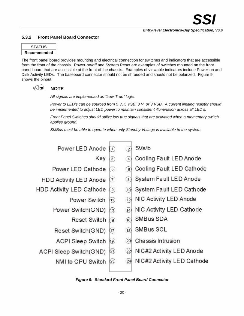
The front panel board provides mounting and electrical connection for switches and indicators that are accessible from the front of the chassis. Power-on/off and System Reset are examples of switches mounted on the front panel board that are accessible at the front of the chassis. Examples of viewable indicators include Power-on and Disk Activity LEDs. The baseboard connector should not be shrouded and should not be polarized. Figure 9 shows the pinout.
/ NOTE
All signals are implemented as “Low-True” logic.
Power to LED’s can be sourced from 5 V, 5 VSB, 3 V, or 3 VSB. A current limiting resistor should be implemented to adjust LED power to maintain consistent illumination across all LED’s.
Front Panel Switches should utilize low true signals that are activated when a momentary switch applies ground.
SMBus must be able to operate when only Standby Voltage is available to the system.
Figure 9: Standard Front Panel Board Connector

SSI
Entry-level Electronics-Bay Specification, V3.0
- 21 -
5.3.3 Front Panel Universal Serial Bus
STATUS Recommended
This section contains feature descriptions of the signals assigned to front panel high-speed serial bus connectors. This section also contains connection information.
The USB 2.0 front panel connector can support multiple USB ports (USBFP_0,1…USBFP_N) that can be routed via cable to the front panel. Each 2 x 5 header supports two ports. For an odd number of ports, the lower numbered or even port should be enabled (PORT0, 2, 4, etc). In the physical layout where a dual-stack USB connector is used, arranging the ports such that the lower connector is the first Port (0) to be enabled allows for a single-port, single-connector implementation without modifying the electrical design. The connector fully supports UHCI. USB features include:
• Support for self-identifying peripherals that can be connected or disconnected while the computer is running
• Automatic mapping of function to driver and configuration
• Support for isochronous and asynchronous transfer types over the same set of wires
• Support for up to 127 physical devices
• Guaranteed bandwidth and low latencies appropriate for telephony, audio, and other applications
• Error-handling and fault-recovery mechanisms built into the protocol
Required baseboard connector: 10-pin Foxconn # HF09101 or equivalent
/ NOTE
Computer systems that have an unshielded cable attached to a USB port may not meet EMC regulatory requirements even if no device or a low-speed USB device is attached to the cable. Use shielded cable that meets the requirements for full-speed devices.
Figure 10: Front Panel High Speed Serial Bus Connector

SSI
Entry-level Electronics-Bay Specification, V3.0
- 22 -
Table 8: Front Panel USB Connector
Pin Signal Name Description
1 VBUS Front Panel USB Power (Ports 0,1)
2 VBUS Front Panel USB Power (Ports 0,1)
3 D- Front Panel USB Port 0 Negative Signal
4 D- Front Panel USB Port 1 Negative Signal
5 D+ Front Panel USB Port 0 Positive Signal
6 D+ Front Panel USB Port 1 Positive Signal
7 Ground
8 Ground
9 Key No Pin
10 Overcurrent Front Panel USB Overcurrent signal (Ports 0,1)

SSI
Entry-level Electronics-Bay Specification, V3.0
- 23 -
5.3.4 Cooling Fan Pinout
STATUS Required
Figure 11 depicts the standard cooling fan connector pinout. The connector should be keyed to prevent damage to the baseboard and fan because of misalignment during insertion. New baseboard designs should make provisions for up to eight fan connectors. Fan-V is the input voltage to the fan. Fans are expected to have a +12 V nominal input.
Required baseboard connector: 3-pin AMP 644953-3 or equivalent
Figure 11: Cooling Fan Pinout

SSI
Entry-level Electronics-Bay Specification, V3.0
- 24 -
5.3.5 Chassis Intrusion Switch
STATUS Recommended
Figure 12 shows the standard chassis intrusion switch pinout. Chassis intrusion may use a number of switches connected in series so that any switch becoming open is detected as a chassis intrusion. The switch type is Normal Open, that is, held in the closed position when the door being monitored is closed.
One end of the series chain is grounded and the other end is pulled up to standby voltage and monitored by the baseboard management controller. A chassis intrusion can be detected when the system has been shut down but A/C power is still available. Figure 13 demonstrates an example of multiple switches.
Required baseboard connector: 2-pin Foxconn # HF06021-P1 or equivalent
Figure 12: Chassis Intrusion Switch Pinout
Figure 13: Multiple Chassis Intrusion Switch Example

SSI
Entry-level Electronics-Bay Specification, V3.0
- 25 -
5.3.6 IPMB Header
STATUS Recommended
The SMBus is used as the media and physical layer for the Intelligent Platform Management Bus (IPMB).
The bus is used to provide a cabled baseboard connection for value-added features and third-party add-in cards, such as Emergency Management Cards, that provide management features using the IPMB.
Devices that connect to the “Type B” SMBus connector must be designed so that they do not ground out the IPMB when the system is powered down.
Devices that attach to the “Type B” SMBus connector must meet the loading specification in Table 9. This corresponds to two SMBus standard-mode device loads. Remaining input and output voltage levels and current drive levels must meet the SMBus specification for standard-mode devices on a 5 V SMBus bus.
Required baseboard connector: 4-pin Molex part number 22-44-7041 or equivalent
Table 9: Type B Connector Device Loading
Parameter Symbol Min. Max. Unit
Input current, per pin (SDA, SCL) Ii -20 20 µA
Capacitance per pin (SDA, SCL) Ci - 20 pF
Table 10: IPMB Connector, Type B Pinout
Pin Signal
1 IPMB_SDA
2 GND
3 IPMB_SCL
4 No Connect

SSI
Entry-level Electronics-Bay Specification, V3.0
- 26 -
5.3.7 ICMB Bridge Header
STATUS Recommended
ICMB is an acronym for an Intelligent Chassis Management Bus that runs outside of the server chassis between separate physical chassis. Addressing on the Intelligent Chassis Management Bus is separate from the Intelligent Platform Management Bus. This header supports connection of an add-on ICMB bridge controller to baseboards that support IPMI/IPMB but do not contain built-in capability.
Required baseboard connector: 4-pin Foxconn part number HF55040-C1 or equivalent
Figure 14: ICMB Connector
/ NOTE
The bus voltage is 5 V.

SSI
Entry-level Electronics-Bay Specification, V3.0
- 27 -
5.4 Hot-plug PCI Connectors
STATUS Optional
Centerline-to-centerline spacing between connectors must be 0.96 inch to maximize the airflow efficiency between hot-swappable PCI cards. The 0.96-inch spacing also allows clearance for mechanical partitioning while providing the maximum number of expansion slots.
The current PCI Local Bus Specification, revision 2.2, “Chapter 5: Mechanical Specification,” shows the 32-bit and 64-bit PCI connectors. Refer to http://www.pcisig.com/.
The .960-inch spacing between adapter card slots for hot-plug baseboards is established by locating the uppermost PCI connector, that is, the farthest connector from the standard ATX mounting hole datum. The pin 1 location of this PCI connector establishes this secondary datum. The benefits are:
• Entry SSI hot-plug baseboards will have six slots possible (the ATX specification allows seven slots at .800-inch spacing).
• The baseboard will fit into a mid-range chassis allowing an upgrade path to a mid-range server board (addition of four slots; up to 10 total) without retooling the chassis. However, hot-plug connector capability in the entry SSI segment will require retooling the rear panel to accommodate the .960-inch spacing and the attachment of LED slot-fault-indicators and slot power-off switches.

SSI
Entry-level Electronics-Bay Specification, V3.0
- 28 -
5.5 Baseboard Electrical Interface Location Requirements
5.5.1 Standard Cutout for Onboard I/O Ports
STATUS Required
The Entry Electronics-Bay Specification includes the I/O aperture of the ATX 2.03 specification and uses the same dimensions. Because the same dimensions are used, a baseboard manufacturer can create just one thin metal shield for the rear I/O connectors, a shield that works in any chassis that meets this specification. This chassis-independent shield closes the Electronics-Bay, except for small openings that allow access to board-mounted connectors such as, but not limited to, network, serial, parallel, video, and mouse/keyboard. The shield provides the chassis shielding and connector grounding that a system requires to meet emissions and susceptibility regulations. Figure 15 shows the Electronics-Bay aperture.
Figure 15: Standard I/O Cutout

SSI
Entry-level Electronics-Bay Specification, V3.0
- 29 -
The 0.1-inch keep-out zone around the I/O cutout area must be clear and free of paint to allow proper attachment of the I/O shield. The chassis sheet metal should not be chemically plated in such a way that the conductive properties of the steel or aluminum will be significantly inhibited. Also, the edges of the I/O cutout should not be rolled, folded, or otherwise modified. The rear panel thickness must be within 0.036 inch and 0.052 inch, as previously shown.
When designing a chassis-independent I/O shield, the board vendor is required to provide a standard distance of 0.038 inches ± 0.010 inches between the connector outer face and the inner surface of the chassis wall supporting the shield. This distance provides an adequate grounding area for the baseboard connector housings necessary to eliminate cable EMI. The AT standard baseboard dimensions for location of the board mounting holes with respect to the I/O connectors ensure that the connectors fit properly within a chassis that also conforms to the AT standard. The ATX and Electronics-Bay specifications use these same dimensions to locate I/O connectors on the baseboard so that the proper connector-to-chassis distance is maintained (Figure 15).
There is no detailed mounting scheme for the I/O shield within this specification. Baseboard vendors may, therefore, devise their own mounting schemes involving clips or press-fit features.
If more positive mounting components such as screws or studs are required, more chassis modifications are required. This limits the number of chassis types available to a system integrator. For an example of an I/O shield that is press-fit on all four sides, see the Appendix.
5.5.2 Mounting Location for Cable-mounted I/O Connectors
STATUS Optional
Although not required by this specification, some provision should be made by the chassis designer for a smaller number of additional connectors to be mounted on the rear surface of the chassis. Server boards often have embedded I/O devices such as SCSI and Fiber Channels that some users may want to connect to external devices. Short cables with chassis-mount connectors can bring these ports to the outside. If space permits, the best location for such connectors is between the I/O cutout and the openings for the adapter(s). This location helps eliminate possible airflow interference by the internal cables. Knockouts for typical connectors can be provided, allowing the system integrator to easily install the required cables. External connections provided in this manner usually give better EMI emissions performance than the same connections made by mounting the connector on a pre-punched I/O adapter plate.

SSI
Entry-level Electronics-Bay Specification, V3.0
- 30 -
5.6 Electronics Bay Cooling
STATUS Recommended
To meet the increased thermal demands, more heat sinks or increased air velocities are required for cooling the Core Logic components. To evacuate the highest possible heat, good system airflow is critical. Airflow is determined by the size and number of fans, vents, and ducts along with their placement in relation to the components and the airflow channels within the system. Also, acoustic noise constraints may limit the size and/or types of fans, vents, and ducts that can be used in a particular design.
To develop a reliable, cost-effective thermal solution, all of the above variables must be considered. Thermal characterization and simulation should be carried out at the entire system level to account for the thermal requirements of each component.
For a zero-airflow restriction inside a computer server, the following relationship is true:
∆=
TQ
fCFM
This relationship states that the volumetric airflow, CFM , is a function of the actual power dissipated, Q , divided
by the temperature rise, T∆ , through the server.
Therefore:
Tables 3 and 4 provide the sum of the worse case thermal design power dissipation for the electronics bay. While the core area produces the major part of power dissipation, the system designer should also be aware of the power dissipation produced by the hard drives, power supply and PCI expansion area. System cooling solutions should design to meet the appropriate cooling requirements. The local maximum ambient temperature and airflow of each zone must be sufficient so that all component temperature specifications will be met.

SSI
Entry-level Electronics-Bay Specification, V3.0
- 31 -
Table 11: Typical Thermal Load for an Entry System
Electronic Bay Volumetric
Description
Typical Thermal Design (Watts) approximate values
Rough CFM
Estimate
Processors - 2 (Next Generation) 150
Memory (4 DIMMs) 32
Chipset 12
Baseboard 40
Total Core 234 42
I/O (3 PCI) 45
NIC 10
Disk Storage
CD ROM / Floppy
5 Drives @ 18W = 90W
5
RAID 25
Total Watts 410 74
Table 12: Maximum Thermal Load
Electronic Bay Volumetric
Description
Maximum Thermal Design (Watts) approximate values
Rough CFM
Estimate
Future processors (2P) 190
Memory (8 DIMMs) 71
Chipset 15
VRM (X2) ~80% efficiency 48
Baseboard 50
Total Core 374 68
I/O (6 PCI) 150
Disk Storage
CD ROM / Floppy
10 Drives @ 18W = 180W
5
Total Watts 710 128

SSI
Entry-level Electronics-Bay Specification, V3.0
- 32 -
A rough estimation is made to obtain an approximate value for the volumetric airflow required to cool 400 watts at altitude, that is, 10,000 feet above sea level.
TCmQ p ∆××=.
Where:
Q = the heat flow
.
m = the mass flow rate of air
pC = the specific heat of air at 10,000 feet
T∆ = the temperature rise of air through the system (see note below on temperature rise)
Rewriting this equation yields:
TC
QCFM
p ∆××=
ρ
Where:
CFM = the volumetric flow rate of air, min
3ft
ρ = the density of air at 10,000 feet at the maximum ambient temperature
/ NOTE
This equation assumes a maximum temperature rise of 15 Cο . An assumption for temperature
rise in computer equipment is generally accepted as 10 or 15 Cο . This equation does not consider system losses or system hot spots.
Determining LFM within the core area with zero losses would yield unsatisfactory results. A detailed thermal analysis is required to understand the effects of temperature rise, pressure loss, and volumetric flow rate onto the system.
Equation Homework:
TC
QCFM
p ∆××=
ρ
Where:
Density, ρ , at 10,000 feet is = .0488 3ft
lbf
Specific heat, pC , at 10,000 feet = 7.56 Clbf
Wο−
− min
Thermal dissipation, Q = given.

SSI
Entry-level Electronics-Bay Specification, V3.0
- 33 -
5.7 Electromagnetic Interference Considerations, EMI
STATUS Recommended
The Electromagnetic Interference (EMI) performance of a system is determined by the degree of noise suppression designed into the baseboard and the provisions for electromagnetic interference containment in the chassis design, including placement of internal subsystems and cables.
In recent years, marketing requirements have changed for computer servers. Requirements now call for compliance to more stringent electromagnetic interference compatibility (EMC) limits such as the CISPR-22 European standard or the U.S. FCC “B” standard. These more restrictive standards, along with higher processor and video frequencies, call for additional chassis containment provisions. The basic design principles have not changed, but the shorter wavelengths call for more frequent ground contacts and shorter apertures in the chassis design.
The baseboard needs to tie into the chassis with the lowest electrical impedance possible. Therefore, the need for metal standoffs and grounded mounting holes is imperative. Baseboard mounting features must provide reliable ground paths to the chassis structure—this is the responsibility of the baseboard designer.
5.8 Baseboard Mechanical Mounting of Memory Riser Boards
STATUS Optional
Although a high-end entry SSI server may include an eight-DIMM memory riser board, the system designer would find it very difficult to mount the board within a variety of compatible entry SSI chassis. The purpose of this section is to propose a mounting solution that defines the location of the memory riser board (MRB) with respect to the baseboard, and thus the chassis as well. A memory riser board that fits within the standard PCI expansion card envelope conforms to the volumetric requirement discussed in Section 5.2, “Volume Constraints.” Furthermore, a memory riser board that fits into this form factor can easily use the expansion card bracket, termed “ISA Bracket” in the PCI Local Bus Specification. However, the memory riser board cannot use the “ISA Retainer” but must extend beyond the standard 12.283-inch “raw card” length. This extended length is necessitated by the length of the individual DIMMs.
Because of baseboard routing issues, the ideal location to place the memory riser board is in the uppermost PCI connector location, that is, in-line, or centered with the PCI location. The baseboard designer may want to alter the position of this connector to gain more baseboard footprint in the core area. A custom ISA bracket would then be needed to support chassis mounting. The DIMMs and other major components of the memory riser board will be placed on the B-side of the card—as defined by the PCI Local Bus Specification. See Figure 16 for details.

SSI
Entry-level Electronics-Bay Specification, V3.0
- 34 -
Figure 16: Memory Riser Board (MRB) Example
SSI
Entry-level Electronics-Bay Specification, V3.0
- 35 -
6 Designing for Workstations This section provides guidance for Workstation platform development using the Entry Electronics Bay specification. Workstations are primarily differentiated from servers by high-end graphics solutions and a desk-side office environment, while they share requirements for large memory capacities, high I/O bandwidth, and powerful processors, particularly in multi-processor configurations. Dual-purpose boards are not uncommon, offering a combination of features applicable to mainstream server and workstation users. This section provides guidance on the selection and placement of those features for workstation baseboard designs, only.
6.1 Connector Placement
STATUS Recommended
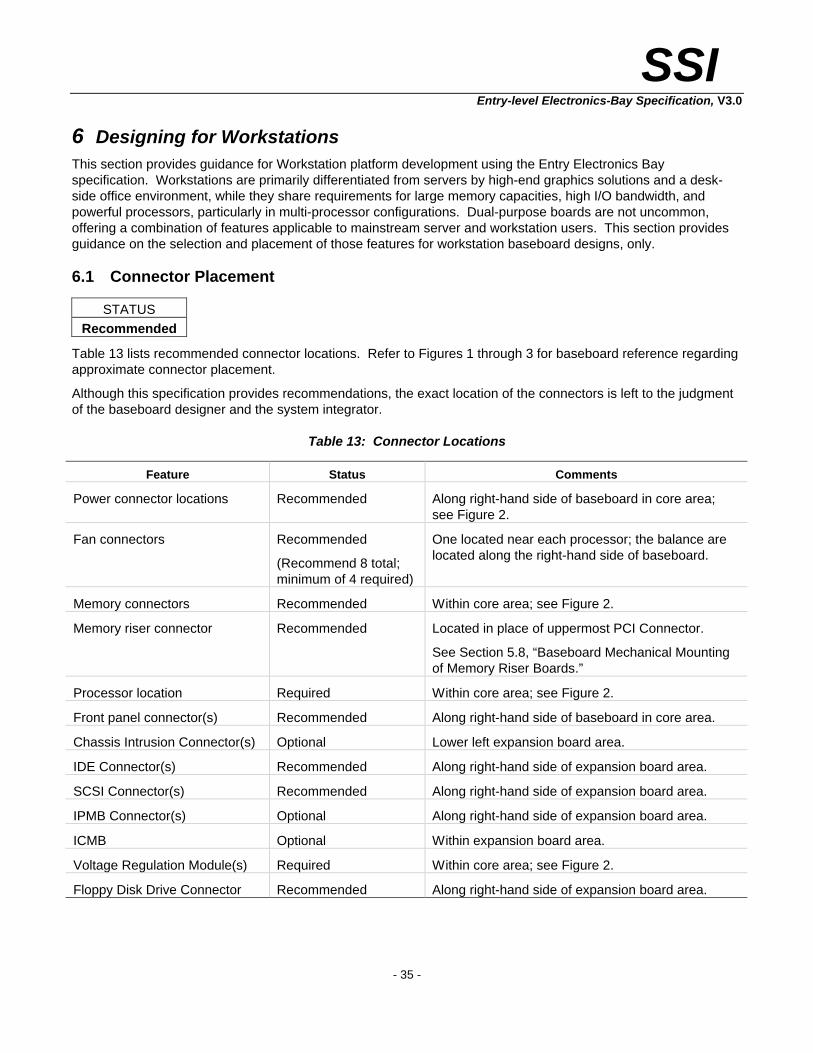
Table 13 lists recommended connector locations. Refer to Figures 1 through 3 for baseboard reference regarding approximate connector placement.
Although this specification provides recommendations, the exact location of the connectors is left to the judgment of the baseboard designer and the system integrator.
Table 13: Connector Locations
Feature Status Comments
Power connector locations Recommended Along right-hand side of baseboard in core area; see Figure 2.
Fan connectors Recommended
(Recommend 8 total; minimum of 4 required)
One located near each processor; the balance are located along the right-hand side of baseboard.
Memory connectors Recommended Within core area; see Figure 2.
Memory riser connector Recommended Located in place of uppermost PCI Connector.
See Section 5.8, “Baseboard Mechanical Mounting of Memory Riser Boards.”
Processor location Required Within core area; see Figure 2.
Front panel connector(s) Recommended Along right-hand side of baseboard in core area.
Chassis Intrusion Connector(s) Optional Lower left expansion board area.
IDE Connector(s) Recommended Along right-hand side of expansion board area.
SCSI Connector(s) Recommended Along right-hand side of expansion board area.
IPMB Connector(s) Optional Along right-hand side of expansion board area.
ICMB Optional Within expansion board area.
Voltage Regulation Module(s) Required Within core area; see Figure 2.
Floppy Disk Drive Connector Recommended Along right-hand side of expansion board area.
SSI
Entry-level Electronics-Bay Specification, V3.0
- 36 -
CAUTION
Due to system cabling issues, it is undesirable to place IDE and SCSI connectors within the expansion board area, unless they are placed along the right-hand side of the board. Furthermore, any ribbon-cable connector should be placed between PCI slots in such a way that the cables do not interfere with long PCI boards. Ribbon cables should be placed so they do not block the air-moving devices.
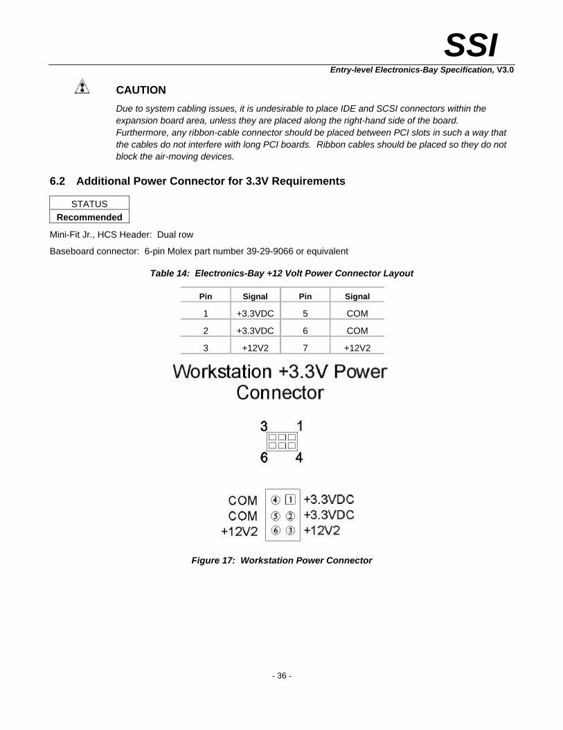
6.2 Additional Power Connector for 3.3V Requirements
STATUS Recommended
Mini-Fit Jr., HCS Header: Dual row
Baseboard connector: 6-pin Molex part number 39-29-9066 or equivalent
Table 14: Electronics-Bay +12 Volt Power Connector Layout
Pin Signal Pin Signal
1 +3.3VDC 5 COM
2 +3.3VDC 6 COM
3 +12V2 7 +12V2
Figure 17: Workstation Power Connector

SSI
Entry-level Electronics-Bay Specification, V3.0
- 37 -
7 Appendix A: Processor Mounting Holes Processor mounting locations are necessary to allow attachment of the processor sub-assembly directly to the chassis frame. Processor and heat sink size and weight considerations necessitate that these components are rigidly fixed to the chassis structure during shipping environments.
The mounting holes shown in Figures 18, 19, & 20 should be supported by all SSI compliant chassis’ in order to allow quick installation of compliant baseboards. Removable standoffs should be utilized to allow flexibility in processor location.
Note that the two placement options shown do not include “shadowing” of the processors. Assuming system front-to-back cooling, that is right-to-left in Figures 18, 19 & 20, it would not be advantages to place one processor in the cooling path or “shadow” of another. This “shadowing” effect limits the cooling of the “shadowed” processor.
7.1 Mounting Hole Option for Next Generation Intel® Xeon™ Processor Baseboards
Figure 18: Processor Hole Mounting Option

SSI
Entry-level Electronics-Bay Specification, V3.0
- 38 -
7.2 Mounting Hole Option for Intel® Xeon™ Processor Baseboards
Figure 19: Processor Hole Mounting Option

SSI
Entry-level Electronics-Bay Specification, V3.0
- 39 -
7.3 Mounting Hole Option for Pentium® III Xeon™ Processor Baseboards
Figure 20: Processor Hole Mounting Option

SSI
Entry-level Electronics-Bay Specification, V3.0
- 40 -
7.4 Alternate Processor Mounting Holes for Next Generation Intel® Xeon™ Processor Baseboards
Figure 21: Processor Hole Mounting Option

SSI
Entry-level Electronics-Bay Specification, V3.0
- 41 -
8 Appendix B: Former Baseboard Mounting Hole Pattern
Figure 22: Former Mounting Hole Pattern

SSI
Entry-level Electronics-Bay Specification, V3.0
- 42 -
9 Appendix C: Example of an I/O Shield Figure 23 shows an example of a chassis-independent I/O shield. This stainless steel shield snaps into the back panel from the inside before the baseboard is put in place.
Figure 23: I/O Shield Example
SSI
Entry-level Electronics-Bay Specification, V3.0
- 43 -
10 Appendix D: Related Documents • ATX Specification, Version 2.03, http://www.formfactors.org/
• Windows NT™ Server Design Guide, http://www.microsoft.com/hwdev/serverdg.htm
• Entry SSI Power Supply Specification, http://www.ssiforum.org/
• Intelligent Platform Management Bus (IPMI) Communications Protocol Specification, http://developer.intel.com/design/servers/ipmi/
• PCI Local Bus Specification, http://www.pcisig.com/
• Universal Serial Bus Specification, Version 2.0, http://www.usb.org/
• For detailed product information: http://developer.intel.com/design/litcentr/index.htm

SSI
Entry-level Electronics-Bay Specification, V3.0
- 44 -
11 Appendix E: Former Power Connector Specification
Figure 24: Former Power Connectors


![Untitled-1 [bharatsanskritiutsab.com]bharatsanskritiutsab.com/pc/prospectus.pdfParticipants / Teams can fill up the entry forms "Online" at www. bharatsanskritiutsab.com. This facility](https://static.documents.pub/doc/80x56/5aacf3b77f8b9a59658dae8f/untitled-1-teams-can-fill-up-the-entry-forms-online-at-www-this-facility.jpg)


