Environmental, Health, and Safety Guidelines PETROLEUM REFINING 2007 version vs 2016 draft revised version DRAFT MARCH 2016 1 WORLD BANK GROUP Environmental, Health, and Safety Guidelines for Petroleum Refining Introduction 1. The Environmental, Health, and Safety (EHS) Guidelines are technical reference documents with general and industry-specific examples of Good International Industry Practice (GIIP) 1 . When one or more members of the World Bank Group are involved in a project, these EHS Guidelines are applied as required by their respective policies and standards. These industry sector EHS guidelines are designed to be used together with the General EHS Guidelines document, which provides guidance to users on common EHS issues potentially applicable to all industry sectors. For complex projects, use of multiple industry -sector guidelines may be necessary. A complete list of industry-sector guidelines can be found at: www.ifc.org/ifcext/enviro.nsf/Content/EnvironmentalGuidelines www.ifc.org/ehsguidelines 2. The EHS Guidelines contain the performance levels and measures that are generally considered to be achievable in new facilities by existing technology at reasonable costs. Application of the EHS Guidelines to existing facilities may involve the establishment of site-specific targets, with an appropriate timetable for achieving them. 3. The applicability of the EHS Guidelines should be tailored to the hazards and risks established for each project on the basis of the results of an environmental assessment in which site-specific variables, such as host country context, assimilative capacity of the environment, and other project factors, are taken into account. The applicability of specific technical recommendations should be based on the professional opinion of qualified and experienced persons. 4. When host country regulations differ from the levels and measures presented in the EHS Guidelines, projects are expected to achieve whichever is more stringent. If less stringent levels or measures than those provided in these EHS Guidelines are appropriate, in view of specific project circumstances, a full and detailed justification for 1 Defined as the exercise of professional skill, diligence, prudence and foresight that would be reasonably expected from skilled and experienced professionals engaged in the same type of undertaking under the same or similar circumstances globally. The circumstances that skilled and experienced professionals may find when evaluating the range of pollution prevention and control techniques available to a project may include, but are not limited to, varying levels of environmental degradation and environmental assimilative capacity as well as varying levels of financial and technical feasibility. This document is NO LONGER IN USE by the World Bank Group. The new version of the World Bank Group Environmental, Health and Safety Guidelines are available at http://www.ifc.org/ehsguidelines
Transcript
Environmental, Health, and Safety GuidelinesPETROLEUM REFINING
2007 version vs 2016 draft revised version
DRAFT MARCH 2016 1
WORLD BANK GROUP
Environmental, Health, and Safety Guidelines
for Petroleum Refining
Introduction
1. The Environmental, Health, and Safety (EHS) Guidelines are technical reference documents with general and
industry-specific examples of Good International Industry Practice (GIIP)1. When one or more members of the World
Bank Group are involved in a project, these EHS Guidelines are applied as required by their respective policies and
standards. These industry sector EHS guidelines are designed to be used together with the General EHS
Guidelines document, which provides guidance to users on common EHS issues potentially applicable to all
industry sectors. For complex projects, use of multiple industry -sector guidelines may be necessary. A complete
list of industry-sector guidelines can be found at: www.ifc.org/ifcext/enviro.nsf/Content/EnvironmentalGuidelines
www.ifc.org/ehsguidelines
2. The EHS Guidelines contain the performance levels and measures that are generally considered to be
achievable in new facilities by existing technology at reasonable costs. Application of the EHS Guidelines to existing
facilities may involve the establishment of site-specific targets, with an appropriate timetable for achieving them.
3. The applicability of the EHS Guidelines should be tailored to the hazards and risks established for each project
on the basis of the results of an environmental assessment in which site-specific variables, such as host country
context, assimilative capacity of the environment, and other project factors, are taken into account. The applicability
of specific technical recommendations should be based on the professional opinion of qualified and experienced
persons.
4. When host country regulations differ from the levels and measures presented in the EHS Guidelines, projects
are expected to achieve whichever is more stringent. If less stringent levels or measures than those provided in
these EHS Guidelines are appropriate, in view of specific project circumstances, a full and detailed justification for
1 Defined as the exercise of professional skill, diligence, prudence and foresight that would be reasonably expected from skilled and experienced professionals engaged in the same type of undertaking under the same or similar circumstances globally. The circumstances that skilled and experienced professionals may find when evaluating the range of pollution prevention and control techniques available to a project may include, but are not limited to, varying levels of environmental degradation and environmental assimilative capacity as well as varying levels of financial and technical feasibility.
This document is NO LONGER IN USE by the World Bank Group. The new version of the World Bank Group Environmental, Health and Safety Guidelines are available at http://www.ifc.org/ehsguidelines
16. There is significant potential for VOC emissions from cone-roof storage tanks during loading and due to fugitive
releases from the out-breathing valves; fugitive emissions of hydrocarbons through the floating roof seals of floating
roof storage tanks; fugitive emissions from flanges and/or valves and machinery seals; VOC emissions from
blending tanks, valves, pumps and mixing operations; and VOC emissions from oily sewage and wastewater
treatment systems. NitrogenIt is also possible for nitrogen to be emitted from bitumen storage tanks may also be emitted,
and possibly containingsaturated with hydrocarbons and sulfur compounds at storage temperature (150–180°C) in
the form of aerosols. Other potential fugitive emission sources include the vapor recovery unit vents and gas
emissionemissions from caustic oxidation.
17. Recommendations to prevent and controllimit fugitive emissions include the following:
Based onA structured leak detection and repair (LDAR) program should be implemented; based on a
systematic review of Process and Instrumentation Diagrams (P&IDs), this program should identify
streams and equipment (e.g. from., pipes, valves, seals, tanks, and other infrastructure components) likely
to lead to , etc.) where fugitive VOC emissions are a possibility (through component degradation, for
example) and prioritize their monitoring with vapor detection equipment, followed by maintenance or
replacement of components, as needed;.
The selection of appropriateWhen selecting valves, flanges, fittings, seals, and packingspacking, consideration
should be based ongiven to their capacity to reducecapability of minimizing gas leaks and fugitive emissions;
3.
To minimize their release to atmosphere, hydrocarbon vapors should be either contained (e.g., using a
nitrogen blanketing system), or routed back to the process system, where the pressure level allows;.
3 European Commission Joint Research Center (EC JRC), Best Available Techniques Reference (BREF) Document for the Refining of Mineral Oil and Gas (2015).
Environmental, Health, and Safety Guidelines PETROLEUM REFINING
2007 version vs 2016 draft revised version
DRAFT MARCH 2016 8
WORLD BANK GROUP
Vapors Recovery Unit, in lieu of open venting or flaring. Use of vent gas scrubbers should be considered
to remove oil and other oxidation products from overhead vapors in specific units (e.g.., bitumen
production);).
The incineration of gas should be conducted at high temperature (approximately 800°C) to ensure
complete destruction of minor components (e.g.., H2S, aldehydes, organic acids, and phenolic
components) and to minimize emissions and odor impacts;.
With regard to emissions from hydrofluoric acid (HF), alkylation plant vents should be collected and
neutralized for HF removal in a scrubber before being sent to flare;.
With regard to naphtha, gasoline, methanol / ethanol, and ethers—including MTBE /, ETBE /, and
TAME—loading / /unloading stationsracks should be provided with vapor recovery units.
Additional guidelines for the prevention and control of fugitive emissions from storage tanks are provided
in the EHS Guidelines for Crude Oil and Petroleum Product Terminals.
Nitrogen Oxides
18. NOx may be emitted from boilers, process heaters, furnaces, Combined Heat Power (CHP) units, gas turbines,
fluid catalytic cracking (FCC) regenerators, flare and other process and combustion units. NOx formation arises
from three mechanisms: Fuel NOx (due to nitrogen content in the fuel), thermal NOx (due to nitrogen in the air
under high temperatures and excess air conditions during combustion), and prompt NOx (due to the reaction of
atmospheric nitrogen (N2) with free radicals such as C, CH, and CH2 fragments derived from fuel in the earliest
stage of combustion). To reduce NOx emissions, low-NOx burners are the most commonly installed technology.
19. The ammonia (NH3) formed during the naphtha and gasoil Hydrodesulfurization process is fed as a component
of the sour feed gas to the thermal reactor of the SRU and converted to fuel NOx. In addition, thermal NOx is formed
at SRU due to high-temperature (approximately 1,400°C) oxidation of nitrogen from the process air.
20. In addition to the guidance for the management of these issues presented in the General EHS Guidelines,
recommended pollution prevention and minimization measure include the following:
High-Temperature Air Combustion (HiTAC), otherwise called flameless (or colorless) combustion, can
be used in SRU, especially those employing lean acid gas streams, which cannot be burned without the
use of auxiliary fuel or oxygen enrichment under standard conditions. With the use of HiTAC, lean acid
gas streams can be burned with uniform thermal fields without the need for fuel enrichment or oxygen
addition. The uniform temperature distribution favors clean and efficient burning, with an additional
advantage of significant reduction of NOx, CO, and hydrocarbon emission.
Environmental, Health, and Safety Guidelines PETROLEUM REFINING
2007 version vs 2016 draft revised version
DRAFT MARCH 2016 9
WORLD BANK GROUP
Sulfur Oxides
21. Sulfur oxides (SOx) and hydrogen sulfide H2S may be emitted from boilers, heaters, and other process
decoking operations, and coke calcinations) based on the sulfur content of the processed crude oil. Sulfur dioxideSO2
and sulfur trioxide (SO3) may be emitted from sulfuric acid regeneration in the sulfuric acid alkylation process. Sulfur
dioxideSO2 in refinery wasteoff gases may have pre-abatement concentration levels of 1500 -75001,500 -7,500
milligrams per cubic meter (mg/m3).4
18.22. To reduce SOx emissions, all refinery acid off-gas streams are typically directed to the hydrotreating unit
where hydrogen combines with sulfur to form hydrogen sulfide (H2S); this, in turn, is directed to the Amine Unit,
from which a single stream, at high H2S concentration, is sent to the Sulfur Recovery Unit (SRU), generally based
on the Claus process5.
19.23. Recommended pollution prevention and minimization measures include the following:
Minimize SOX emissions through desulfurization of fuels, to the extent feasible, or by directing the use
of high-sulfur fuels to units equipped with SOX emission controls;.
Recover sulfur from tail gases using high-efficiency sulfur recovery unitsSRUs (e.g.., Claus units);, equipped
with the specific section of Tail Gas Treatment (TGT)).6
Install mist precipitators (e.g. electrostatic precipitators or brink demisters ) to remove sulfuric acid mist;
Install scrubbers with caustic soda solution to treat flue gases (caustic wash of acid gas stream, to
remove acids) from the alkylation unit absorption towers.
Particulate Matter
20.24. Particulate emissions from refinery units are associated with flue gas from furnaces, boilers; catalyst fines
emitted from fluidized catalytic cracking regeneration units and other catalyst-based chemical processes; the
handling of pet-coke; and fines and ash generated during incineration of sludges.sludge; and decoking and soot
blowing off furnaces and flares. Particulates may contain metals (e.g.., vanadium, nickelsnickel). Measures to control
particulateparticulates may also contribute to control of metal emissions from petroleum refining.7
21.25. Recommended pollution prevention and minimization measures include the following:
4 EIPPCB BREF (2003) European Integrated Pollution Prevention and Control Bureau (EIPPCB), “Best Available Techniques Reference (BREF),” (2003). 5 See Annex A: General Description of Petroleum Industry Activities. 6 A sulfur recovery system with at least 97 percent but preferably over 99 percent sulfur recovery should be used when the hydrogen sulfide concentration in tail gases is significant. 7 EIPPCB, BREF (2003)).
Environmental, Health, and Safety Guidelines PETROLEUM REFINING
2007 version vs 2016 draft revised version
DRAFT MARCH 2016 10
WORLD BANK GROUP
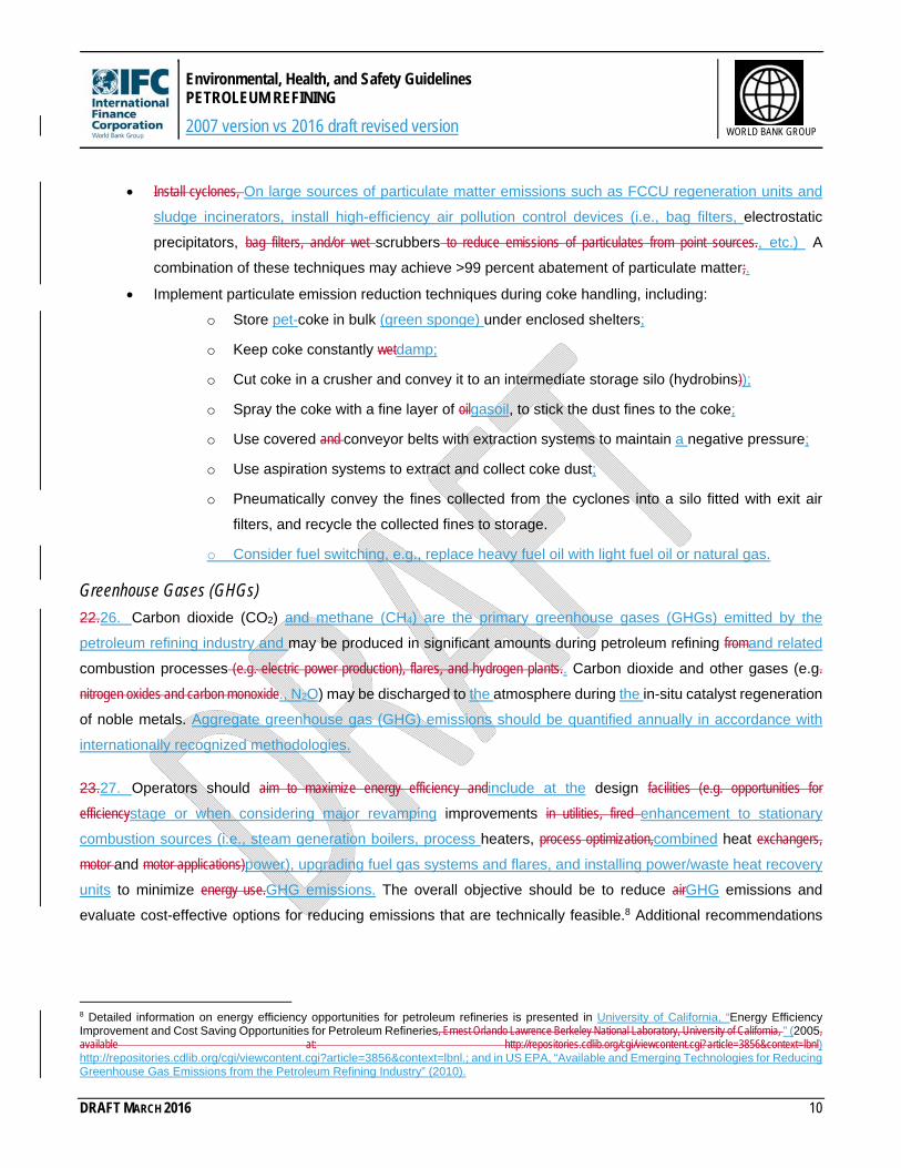
Install cyclones, On large sources of particulate matter emissions such as FCCU regeneration units and
sludge incinerators, install high-efficiency air pollution control devices (i.e., bag filters, electrostatic
precipitators, bag filters, and/or wet scrubbers to reduce emissions of particulates from point sources., etc.) A
combination of these techniques may achieve >99 percent abatement of particulate matter;.
Implement particulate emission reduction techniques during coke handling, including:
o Store pet-coke in bulk (green sponge) under enclosed shelters;
o Keep coke constantly wetdamp;
o Cut coke in a crusher and convey it to an intermediate storage silo (hydrobins));
o Spray the coke with a fine layer of oilgasoil, to stick the dust fines to the coke;
o Use covered and conveyor belts with extraction systems to maintain a negative pressure;
o Use aspiration systems to extract and collect coke dust;
o Pneumatically convey the fines collected from the cyclones into a silo fitted with exit air
filters, and recycle the collected fines to storage.
o Consider fuel switching, e.g., replace heavy fuel oil with light fuel oil or natural gas.
Greenhouse Gases (GHGs)
22.26. Carbon dioxide (CO2) and methane (CH4) are the primary greenhouse gases (GHGs) emitted by the
petroleum refining industry and may be produced in significant amounts during petroleum refining fromand related
combustion processes (e.g. electric power production), flares, and hydrogen plants.. Carbon dioxide and other gases (e.g.
nitrogen oxides and carbon monoxide., N2O) may be discharged to the atmosphere during the in-situ catalyst regeneration
of noble metals. Aggregate greenhouse gas (GHG) emissions should be quantified annually in accordance with
internationally recognized methodologies.
23.27. Operators should aim to maximize energy efficiency andinclude at the design facilities (e.g. opportunities for
efficiencystage or when considering major revamping improvements in utilities, fired enhancement to stationary
combustion sources (i.e., steam generation boilers, process heaters, process optimization,combined heat exchangers,
motor and motor applications)power), upgrading fuel gas systems and flares, and installing power/waste heat recovery
units to minimize energy use.GHG emissions. The overall objective should be to reduce airGHG emissions and
evaluate cost-effective options for reducing emissions that are technically feasible.8 Additional recommendations
8 Detailed information on energy efficiency opportunities for petroleum refineries is presented in University of California, “Energy Efficiency Improvement and Cost Saving Opportunities for Petroleum Refineries, Ernest Orlando Lawrence Berkeley National Laboratory, University of California, ” (2005, available at: http://repositories.cdlib.org/cgi/viewcontent.cgi?article=3856&context=lbnl) http://repositories.cdlib.org/cgi/viewcontent.cgi?article=3856&context=lbnl.; and in US EPA, “Available and Emerging Technologies for Reducing Greenhouse Gas Emissions from the Petroleum Refining Industry” (2010).
Environmental, Health, and Safety Guidelines PETROLEUM REFINING
2007 version vs 2016 draft revised version
DRAFT MARCH 2016 11
WORLD BANK GROUP
for the management of GHGs, in addition to energy efficiency and conservation, are addressed in the General EHS
Guidelines.
Wastewater
Industrial Process Wastewater
24.28. The largest volume effluentsSignificant volumes of wastewaters in petroleum refining include “sour” process
waterwastewater and non-oily/non-sour but highly alkaline process water. wastewater. Sour waterwastewater is
generated from desalting, topping, vacuum distillation, pretreating, light- and middle-distillate
hydrodesulphurizationhydrodesulfurization, hydrocracking, catalytic cracking, coking, and visbreaking / /thermal
cracking. Sour waterwastewater may be contaminated with hydrocarbons, hydrogen sulfide, ammoniaH2S, NH3, organic
sulfur compounds, (R-S-H mercaptans), organic acids, and phenol. Process waterwastewater that is high in H2S
and/or NH3 is treated in the Sour Water Stripper Unit (SWSSWSU) to remove hydrocarbons, hydrogen sulfide,
ammoniathese and other compounds, before recycling for internal process uses, or before final treatment and
disposal through an onsiteon-site wastewater treatment unit. Non-oily / /non-sour but highly alkaline process
waterwastewater has the potential to cause Waste Water Treatment Plant upsets. wastewater treatment plant (WWTP)
disturbances. Boiler blowdown and demineralization plant reject streams in particular, if incorrectly neutralized, have the
undesirable potential to extract phenolicsphenolic compounds from the oil phase into the water phase, as well as
cause emulsions in the WWTP. if incorrectly neutralized. Liquid effluentwastewater may also result from accidental
releases or leaks of small quantities of products from process equipment, machinery, and storage areas/tanks.
25.29. Recommended process wastewater management practices include:
Prevention and control of accidental releases of liquids through regular inspections and maintenance of
storagesstorage and conveyance systems, including stuffing boxes on pumps and valves and other
potential leakage points, as well as the implementation of spill response plans;
Provision of sufficient capacity for storing process fluids let-down capacity to maximizeenable maximum
recovery into the process and avoid massive discharge, as a consequence, avoiding large discharges of
process liquids into the oily waterwastewater drainage system;
Design and construction of wastewater and hazardous materials storage containment basins with
suitably impervious surfaces to prevent infiltration of contaminated water into soil and groundwater;
Segregation of process waterwastewater from stormwaterstorm water and segregation of wastewater and
hazardous materials containment basins;
Implementation of good housekeeping practices, including conducting product transfer activities over
paved areas and prompt collection of small spills.
Environmental, Health, and Safety Guidelines PETROLEUM REFINING
2007 version vs 2016 draft revised version
DRAFT MARCH 2016 12
WORLD BANK GROUP
26.30. Specific provisions to be considered for the management of individual wastewater streams include the
following:
Direct spent caustic soda from sweetening units and chemical treating routed to the wastewater treatment
system following caustic oxidation;.
Direct spent caustic liquor from the caustic oxidation (containing soluble thiosulfates, sulfitessulphites, and
sulfatessulphates) to the wastewater treatment system;.
Install a closed-process drain system to collect and recover leakages and spills of MTBE, ETBE, and
TAME. These substances are not conduciveresponsive to biological treatment, and should be prevented
from entering and adversely affecting the wastewater treatment system;.
If present at the facility, acidic and caustic effluentswastewater from the demineralized water preparation
should be neutralized prior to discharge into the wastewater treatment system;.
Cool blowdown from the steam generation systems prior to discharge. This effluentwastewater, as well
as blowdown from cooling water towers, may contain additives (e.g.., biocides) andthat may require
treatment in the wastewater treatment plantWWTP prior to discharge;.
Hydrocarbons Hydrocarbon-contaminated water from scheduled cleaning activities during facility turn-around
(cleaning activities typically are performed annually and may last several few weeks)turnaround and hydrocarbon-
containing effluentswastewaters from process leaks should be treated in the wastewater treatment
plantWWTP.
Process Wastewater Treatment
27.31. Techniques for treating industrial process wastewater in this sector include source segregation and
pretreatment of concentrated wastewater streams. Typical wastewater treatment steps include:
Grease traps, oil skimmers, dissolved air floatationCoalescing Plate Separators (CPS), Dissolved Air
Flotation (DAF) or oil water separators for separation of oils and floatable solids;
Filtration for separation of filterable solids;
Flow and load equalization;
Sedimentation for suspended solids reduction using clarifiers;
Biological treatment, —typically aerobic treatment, —for the reduction of soluble organic matter (BOD);
Chemical or biological nutrient removal for reduction inof nitrogen and phosphorus;
Chlorination of effluentwastewater when disinfection is required;
Dewatering and disposal of residuals in designated hazardous waste landfills.
28.32. Additional engineering controls may be required for: (i) containment and treatment of volatile organics
stripped from various unit operations in the wastewater treatment system,; (ii) advanced metals removal using
Environmental, Health, and Safety Guidelines PETROLEUM REFINING
2007 version vs 2016 draft revised version
DRAFT MARCH 2016 13
WORLD BANK GROUP
membrane filtration or other physical/chemical treatment technologies,; (iii) removal of recalcitrant organics and
non-biodegradable COD using activated carbon or advanced chemical oxidation,; (iii) reduction in effluentwastewater
toxicity using appropriate technology (such as reverse osmosis, ion exchange, activated carbon, etc.),.); and (iv)
containment and neutralization of nuisance odors.
29.33. Management of industrial wastewater and examples of treatment approaches are discussed in the General
EHS Guidelines. Through the use of these technologies and good practice techniques for wastewater
management, facilities should meet the Guideline Values for wastewater discharge as indicated in the relevant table
of Section 2 of this industry sector document.
Other Wastewater Streams & Water Consumption
30.34. Guidance on the management of non-contaminated wastewater from utility operations, non-contaminated
stormwaterstorm water, and sanitary sewage is provided in the General EHS Guidelines. Contaminated streams
should be routed to the treatment system for industrial process wastewater. Recommendations to reduce water
consumption, especially where it may be a limited natural resource, are provided in the General EHS Guidelines.
31.35. Hydrostatic Testing Water: Hydrostatic testing (hydro-test) of equipment and pipelines involves pressure
testing with water (generally, filtered raw-water),) to verify system integrity and to detect possible leaks. Chemical
additives (e.g.., a corrosion inhibitor, an oxygen scavenger, and a dye) are oftengenerally added to the fresh water
to prevent internal corrosion. In managing hydrotesthydro-test waters, the following pollution prevention and control
measures should be implemented:
UsingUse the same water for multiple tests;
ReducingReduce the need for corrosion inhibitors and other chemicals by minimizing the time that test
water remains in the equipment or pipeline;
If chemical use is necessary, selection ofselect effective chemicals with the lowest toxicity, biodegradability,
bioavailability, and bioaccumulation potential, and with the highest biodegradability.
32.36. If discharge of hydrotesthydro-test waters to the sea or to surface water is the only feasible alternative for
disposal, a hydrotesthydro-test water disposal plan should be prepared that considers points of discharge, rate of
discharge, chemical use and dispersion, environmental risk, and required monitoring. HydrotestHydro-test water
disposal into shallow coastal waters should be avoided.
Handling of Hazardous Materials
33.37. Petroleum refining facilities manufacture, use, and store significant amounts of hazardous materials,
including raw materials, intermediate / /final products, and by-products. Recommended practices for hazardous
Environmental, Health, and Safety Guidelines PETROLEUM REFINING
2007 version vs 2016 draft revised version
DRAFT MARCH 2016 14
WORLD BANK GROUP
material management, —including handling, storage, and transport, —are presented in the EHS Guidelines for
Crude Oil and Petroleum Product Terminals and in the General EHS Guidelines.
Wastes
Wastes
Hazardous Wastes: Spent Catalysts
34.38. Spent catalysts result from several process units in petroleum refining, including the pretreating and
catalytic reformer; light- and middle-distillate hydrodesulphurizationhydrodesulfurization; the hydrocracker; fluid catalytic
cracking (FCCU); residue catalytic cracking (; RCCU);; MTBE/ETBE and TAME production; butanes isomerization; the
dienes hydrogenation and butylenes hydroisomerizationhydro-isomerization unit; sulfuric acid regeneration; selective
catalytic hydrodesulphurizationhydrodesulfurization; and the sulfur and hydrogen plants. Spent catalysts may contain
molybdenum, nickel, cobalt, platinum, palladium, vanadium iron, copper, and silica and/or alumina, as carriers.
35.39. Recommended management strategies for catalysts include the following:
Use long-life catalysts and regeneration to extend the catalyst life cycle;
Use appropriate on-site storage and handling methods, (e.g., submerging pyrophoric spent catalysts in
water during temporary storage and transport until they can reach the final point of treatment to avoid
uncontrolled exothermic reactions);
Return spent catalysts to the manufacturer for regeneration or recovery, or transport to other off-site
management companies for handling, heavy or precious metals recovery / /recycling, and disposal in
accordance with industrial waste management recommendations included in General EHS Guidelines.
Other Hazardous Wastes
36.40. In addition to spent catalysts, industryindustrial hazardous waste may include solvents, filters, mineral spirits,
used sweetening, spent amines for CO2, hydrogen sulfide (H2S) and carbonyl sulfide (COS) removal, activated carbon
filters and oily sludge from oil / /water separators, tank bottoms, and spent or used operational and maintenance
fluids (e.g.., oils and test liquids). Other hazardous wastes, including contaminated sludges, sludge from jet water
pump circuit purification, exhausted molecular sieves, and exhausted alumina from hydrofluoric (HF) alkylation,
may be generated from crude oil storage tanks, desalting and topping, coking, propane, propylene, butanes streams
dryers, and butanes isomerization. WWTPs generate sludge that may need to be considered as hazardous waste,
depending on the treatment process itself and on the incoming wastewater.
37.41. Process wastes should be tested and classified as hazardous or non-hazardous based on local regulatory
requirements or internationally accepted approaches. Detailed guidance on the storage, handling, treatment, and
disposal of hazardous and non-hazardous wastes is provided in the General EHS Guidelines.
Environmental, Health, and Safety Guidelines PETROLEUM REFINING
2007 version vs 2016 draft revised version
DRAFT MARCH 2016 15
WORLD BANK GROUP
38.42. Recommended industry-specific management strategies for hazardous waste include the following:
Send oily sludges such as those from crude oil storage tanks (bottom drains) and thefrom desalter
(bottom drains) to the delayed coking drum, where applicable, to recover the hydrocarbons;.
Ensure excessive cracking is not conducted in the visbreaking unit to prevent production of an unstable
fuel oil, resulting in increased sludge and sediment formation during storage;.
Maximize recovery of oil from oily wastewaters and sludges. Minimize losses of oil to the
effluentwastewater system. Oil can be recovered from slops using separation techniques (e.g.., gravity
separators and centrifuges);).
Sludge treatment may include land application (bioremediation),) or solvent extraction, followed by
combustion of the residue and / /or use in asphalt or cement kilns, where feasible. In some cases, the
residue may require stabilization prior to disposal to reduce the leachability of toxic metals. When not
treated, the hazardous sludge from crude oil refineries must be disposed of in a secured landfill, as
indicated in the General EHS Guidelines.
Non-hazardous Wastes
39.43. Hydrofluoric acidHF alkylation produces neutralization sludgessludge, which may contain calcium fluoride,
calcium hydroxide, calcium carbonate, magnesium fluoride, magnesium hydroxide and magnesium carbonate. After
drying and compression, they may be marketed for uses—such as in steel mills use —or landfilled. Detailed guidance
on the storage, handling, treatment, and disposal of non-hazardous wastes is provided in the General EHS
Guidelines.
Noise
40.44. The principal sources of noise in petroleum refining facilities include large rotating machines, such as
compressors and turbines, pumps, electric motors, air coolers (if any), blowers, fans, and heaters. During
emergency depressurization, high noise levels can be generated due to high-pressure gases released to flare
and/or steam release into the atmosphere. General recommendations for noise management are provided in the
General EHS Guidelines.
1.2 Occupational Health and Safety
41.45. The occupational health and safety issues that may occur during the construction and decommissioning of
petroleum refining facilities aremay be similar to those of other industrial facilities, and their management is
discussed in the General EHS Guidelines.
42.46. Facility-specific occupational health and safety issues should be identified based on job safety analysis or comprehensive hazard
or risk assessment, using established methodologies such as a hazard identification study [HAZID], hazard and operability study [HAZOP],
Environmental, Health, and Safety Guidelines PETROLEUM REFINING
2007 version vs 2016 draft revised version
DRAFT MARCH 2016 16
WORLD BANK GROUP
or a quantitative risk assessment [QRA]. As a general approach,As a general approach, process health and safety
management planning should include the adoption of a systematic and structured approach for the prevention and
control of physical, chemical, biological, and radiological health and safety hazards described in the General EHS
Guidelines.
47. Major occupational health and safety hazards should be prevented through the implementation of a Process
Safety Management Program that includes all of the minimum elements outlined in the General EHS Guidelines,
including:
Facility-wide risk analysis, including a detailed consequence analysis (e.g., failure mode and effects
analysis (FMEA), hazard identification study (HAZID), hazard and operability study (HAZOP), or
quantitative risk assessment (QRA)). This analysis is expected to be carried out alongside the Front End
Engineering Design (FEED) and with the Detailed Engineering Design prior to commissioning.
Employee training on operational hazards;
Procedures for the management of change in operations, process hazard analysis, maintenance of
mechanical integrity, pre-start review, hot work permits, safe systems of work (SSW), and other essential
aspects of process safety included in the General EHS Guidelines;
Safe Transportation Management System, as noted in the General EHS Guidelines, if the project
includes a transportation component for raw or processed materials;
Procedures for handling and storage of hazardous materials.
43.48. The most significant occupational health and safety hazards occurprevalent during the operational phase of
a petroleum refining facility and primarily include:
Process safety;
Oxygen-deficient atmosphere;
Chemical hazards;
Fire and explosions.
Process Safety
44.49. Process safety programs should be implemented, due to based on industry-specific characteristics,
includingconditions, such as complex chemical reactions, use of hazardous materials (e.g. ., toxic, reactive, volatile,
flammable, or explosive compounds), and) multi-step reactions. , etc.
45.50. Process safety management includesshould include the following actions:
Physical hazard testing of materials and reactions;
Environmental, Health, and Safety Guidelines PETROLEUM REFINING
2007 version vs 2016 draft revised version
DRAFT MARCH 2016 17
WORLD BANK GROUP
Hazard analysis studies to review the process chemistry and engineering practices, including
thermodynamics and kinetics;
Examination of Effective preventive maintenance androutines and examination of the mechanical integrity
of the process equipment and utilities;
WorkerOperator/technician training; and development; and
Development of SSW, operating instructions, and emergency response procedures.
Oxygen-Deficient Atmosphere
46.51. The potential release and accumulation of nitrogen gas into work areas may result in the creation of
asphyxiating conditions due to the displacement of oxygen. Prevention and control measures to reduce the risks of
asphyxiant gas release include:
Design and placement of nitrogen venting systems according to industry standards;
Installation of an automatic Emergency Shutdown System that can detect and warnsound an alarm
warning of the uncontrolled release of nitrogen (including the presence of oxygen-deficient
atmospheres in working areas9), automatically initiate forced ventilation, and shut down equipment to
minimize the duration of releases;
Implementation of confined space entry procedures as described in the General EHS Guidelines,
with consideration of facility-specific hazards.
Chemical Hazards
47.52. Releases of hydrofluoric acid, carbon monoxide, methanol, and hydrogen sulfideH2S may present occupational
exposure hazards. Hydrogen sulfideH2S leakage may occur from amine regeneration in amine treatment units and
sulfur recovery units. Carbon monoxideSRUs CO leakage may occur from FluidFCCU and Residue Catalytic Cracking
UnitsRCCU and from the syngas production section of the Hydrogen Plant. Carbon monoxide / CO/air mixtures are
explosive and spontaneous /; explosive re-ignition may occur. Hydrogen sulfideH2S poses an immediate fire hazard
when mixed with air.
48.53. Workers may be exposed to potential inhalation hazards (e.g. hydrogen sulfide, carbon monoxide., H2S, CO,
VOCs, polycyclic aromatic hydrocarbons (PAHs) during routine plant operations. Dermal hazards may include contact
with acids, steam, and hot surfaces. Chemical hazards should be managed based on the results of a job safety
analysis and industrial hygiene survey and according to the occupational health and safety guidance provided in
9 Working areas with the potential for oxygen-deficient atmospheres should be equipped with area monitoring systems capable of detecting such conditions. Workers also should be equipped with personal monitoring systems. Both types of monitoring systems should be equipped with a warning alarm set at 19.5 percent concentration of O2 in the air.
Environmental, Health, and Safety Guidelines PETROLEUM REFINING
2007 version vs 2016 draft revised version
DRAFT MARCH 2016 18
WORLD BANK GROUP
the General EHS Guidelines. Protection measures include worker training, work permit systems, use of personal
protective equipment (PPE), and toxic gas detection systems with alarms.10
Hydrofluoric Acid
49.54. Workers may be exposed to hydrofluoric acid (HF) in the HF alkylation unit. Occupational safety measures
include the following:11
Reducing HF volatility by adding suitable vapor pressure suppression additives;
Designing the plant lay-outlayout to limit the extent of the plant area exposed to potential HF hazards,
and to facilitate escape routes for workers;
Clearly identifying HF hazardous HF areas, and indicating where PPE shouldmust be adopted;
Implementing a worker decontamination procedure in a dedicated area;
Implementing a safety distance buffer between the HF alkylation unit, other process units, and the
refinery boundary;
Use of scrubbing systems to neutralizingneutralize and remove HF prior to flaring;
Use of a HF neutralization basin for effluentswastewater before they areit is discharged into the refinery
oily sewagewastewater system;
Use of a dedicated tank to collect alkylate product and undertake routine pH measurements before
dispatching to gasoline pool;
Treating butane and propane products in alumina defluorinators to destroy organic fluorides, followed
by alkali to remove any remaining HF;
Transport of HF to and from the plant should be handled according to guidance for the transport of
dangerous goods, as described in the General EHS Guidelines.
Fire and Explosions
50.55. Fire and explosion hazards generated by process operations include the accidental release of syngas
(containing carbon monoxide and hydrogen), oxygen, methanol, and refinery gases. Refinery gas releases may
cause ‘“jet fires’,fires” if ignited in the release section, or give rise to a vapor cloud explosion (VCE), fireball, or flash
fire, depending on the quantity of flammable material involved and the degree of confinement of the cloud. Methane,
hydrogen, carbon monoxide, and hydrogen sulfideH2S may ignite even in the absence of ignition sources, if their
10 A detailed description of health and safety issues and prevention/control strategies associated with petroleum refining, including chemical and fire/explosion hazards, is available in Occupational Safety and Health Association (OSHA)), Technical Manual, Section IV Safety Hazards, Chapter 2. (1999) “Petroleum Refining Process,,” available at http://www.osha.gov/dts/osta/otm/otm_iv/otm_iv_2.htmlhttp://www.osha.gov/dts/osta/otm/otm_iv/otm_iv_2.html. 11 Recommendations for the handling of hydrofluoric acid are available in American Petroleum Institute (API), Recommended Practice (RP) 751. , “Safe Operation of Hydrofluoric Acid Alkylation Units (1999). ” (Third Edition, June 2007).
Environmental, Health, and Safety Guidelines PETROLEUM REFINING
2007 version vs 2016 draft revised version
DRAFT MARCH 2016 19
WORLD BANK GROUP
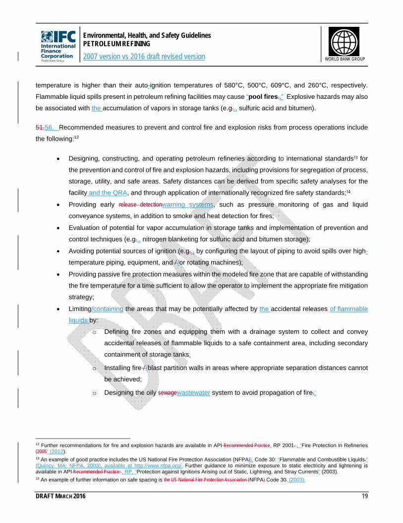
temperature is higher than their auto-ignition temperatures of 580°C, 500°C, 609°C, and 260°C, respectively.
Flammable liquid spills present in petroleum refining facilities may cause “pool fires..” Explosive hazards may also
be associated with the accumulation of vapors in storage tanks (e.g.., sulfuric acid and bitumen).
51.56. Recommended measures to prevent and control fire and explosion risks from process operations include
the following:12
Designing, constructing, and operating petroleum refineries according to international standards13 for
the prevention and control of fire and explosion hazards, including provisions for segregation of process,
storage, utility, and safe areas. Safety distances can be derived from specific safety analyses for the
facility and the QRA, and through application of internationally recognized fire safety standards;14
Providing early release detectionwarning systems, such as pressure monitoring of gas and liquid
conveyance systems, in addition to smoke and heat detection for fires;
Evaluation of potential for vapor accumulation in storage tanks and implementation of prevention and
control techniques (e.g.., nitrogen blanketing for sulfuric acid and bitumen storage);
Avoiding potential sources of ignition (e.g.., by configuring the layout of piping to avoid spills over high-
temperature piping, equipment, and / /or rotating machines);
Providing passive fire protection measures within the modeled fire zone that are capable of withstanding
the fire temperature for a time sufficient to allow the operator to implement the appropriate fire mitigation
strategy;
Limiting/containing the areas that may be potentially affected by the accidental releases of flammable
liquids by:
o Defining fire zones and equipping them with a drainage system to collect and convey
accidental releases of flammable liquids to a safe containment area, including secondary
containment of storage tanks;
o Installing fire / /blast partition walls in areas where appropriate separation distances cannot
be achieved;
o Designing the oily sewagewastewater system to avoid propagation of fire.;
12 Further recommendations for fire and explosion hazards are available in API Recommended Practice, RP 2001. , “Fire Protection in Refineries (2005” (2012). 13 An example of good practice includes the US National Fire Protection Association (NFPA)), Code 30: “Flammable and Combustible Liquids.” (Quincy, MA: NFPA, 2003), available at http://www.nfpa.org/. Further guidance to minimize exposure to static electricity and lightening is available in API Recommended Practice: , RP, “Protection against Ignitions Arising out of Static, Lightning, and Stray Currents” (2003). 14 An example of further information on safe spacing is the US National Fire Protection Association (NFPA) Code 30. (2003).
Environmental, Health, and Safety Guidelines PETROLEUM REFINING
2007 version vs 2016 draft revised version
DRAFT MARCH 2016 20
WORLD BANK GROUP
52.57. Further recommendations on the management of fire and explosion hazards relating to crude oil storage
are addressed in the EHS Guidelines for Crude Oil and Petroleum Product Terminals.
1.3 Community Health and Safety
53.58. Community health and safety impacts during the construction and decommissioning of petroleum refining
facilities are common to those of most other industrial facilities and are discussed in the General EHS Guidelines.
54.59. The most significant community health and safety hazards associated with petroleum refining facilities occur
during the operational phase, including the threat from major accidents related to fires and explosions at the facility
and potential accidental releases of raw materials or finished products during transportation outside the processing
facility. Guidance for the management of these issues is presented below and in the General EHS Guidelines.
55.60. Additional relevant guidance applicable to the transport by sea and rail as well as shore-based facilities can
be found in the EHS Guidelines for Shipping;, Railways;, Ports and Harbors;, and Crude Oil and Petroleum
Products Terminals.
Major Hazards15
56. The most significant safety hazards are related to the handling and storage of liquid and gaseous
substances. Impacts may include significant exposures to workers and, potentially, to surrounding communities,
depending on the quantities and types of accidentally released chemicals and the conditions for reactive or
catastrophic events, such as fire and explosion.16
57. Major hazards should be prevented through the implementation of a Process Safety Management Program that includes all of
the minimum elements outlined in the respective section of the General EHS Guidelines including:
Facility wide risk analysis, including a detailed consequence analysis for events with a likelihood above 10-6/year (e.g. HAZOP,
HAZID, or QRA);
Main measures for reduction of these risks are presented in Section 1.2. Emergency planning, to
prevent major hazards to the community Employee training on operational hazards;
Procedures for management of change in operations, process hazard analysis, maintenance of mechanical integrity, pre-start review,
hot work permits, and other essential aspects of process safety included in the General EHS Guideline;
15 A detailed description of health and safety issues and prevention / /control strategies associated with petroleum refining, is available in Occupational Safety and Health Association (OSHA), Technical Manual, Section IV Safety Hazards, Chapter 2 (1999) “Petroleum Refining Process”, 1999,,” available at http://www.osha.gov/dts/osta/otm/otm_iv/otm_iv_2.htmlhttp://www.osha.gov/dts/osta/otm/otm_iv/otm_iv_2.html. 16 Further recommendations for fire and explosion hazards are available in API Recommended Practice, RP 2001, “Fire Protection in Refineries”, 2005.” (2012).
Environmental, Health, and Safety Guidelines PETROLEUM REFINING
2007 version vs 2016 draft revised version
DRAFT MARCH 2016 21
WORLD BANK GROUP
Safe Transportation Management System as noted in the General EHS Guidelines if the project includes a transportation component
for raw or processed materials;
Procedures for handling and storage of hazardous materials;
58.61. Emergency planning, which should include, at a minimum, the preparation and implementation of an Emergency
Management Plan, prepared with the participation of local authorities and potentially affected communities.
Additional guidance is provided in the General EHS Guidelines.
Environmental, Health, and Safety Guidelines PETROLEUM REFINING
2007 version vs 2016 draft revised version
DRAFT MARCH 2016 22
WORLD BANK GROUP
2.0 Performance Indicators and Monitoring
2.1 Environment
Emissions and Effluent Guidelines
59.62. Tables 1 and 2to 3 present emission and effluent guidelines for thisthe Petroleum Refining sector. Guideline
values for process emissions (such as FCCU, SRU and combustion units) and effluents in this sector are indicative
of good international industry practice, as reflected in relevant standards of countries with recognized regulatory
frameworks. The guidelinesguideline values are assumed to be achievable under normal operating conditions in
appropriately designed and operated facilities through the application of pollution prevention and control techniques
discussed in the preceding sections of this document.
60.63. Combustion source emissions guidelines associated with steam- and power-generation activities from
sources with a capacity equal to or lower than 50 MWth are addressed in the General EHS Guidelines with. Larger
power source emissions from turbines, boilers and engines are addressed in the Thermal Power EHS Guidelines.
Emissions from multi-fuel fired combustion units such as process heaters and boilers are addressed in Table 1
below together with other process emissions. Guidance on ambient considerations based on the total load of
emissions is provided in the General EHS Guidelines.
61.64. Effluent guidelines are applicable for direct discharges of treated effluents to surface waters for general
use. Site-specific discharge levels may be established based on the availability and conditions in use of publicly
operated sewage collection and treatment systems or, if discharged directly to surface waters, on the receiving
water use classification, as described in the General EHS Guidelines.
Environmental, Health, and Safety Guidelines PETROLEUM REFINING
2007 version vs 2016 draft revised version
DRAFT MARCH 2016 23
WORLD BANK GROUP
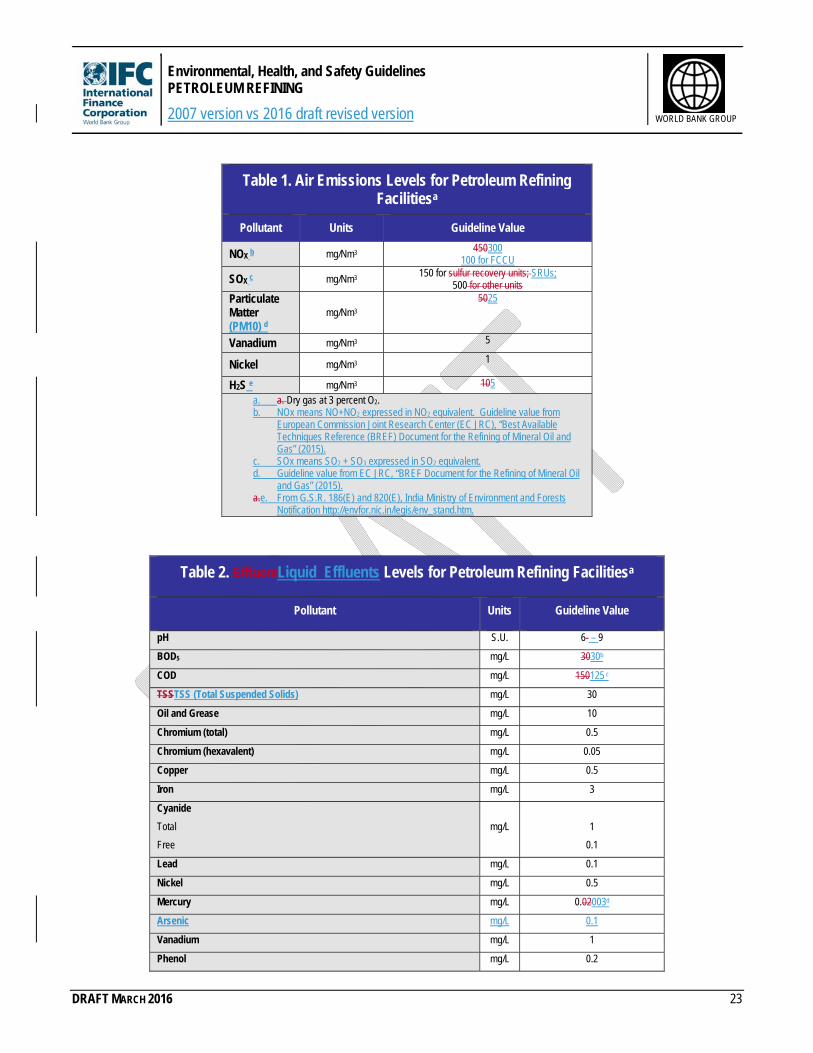
Table 1. Air Emissions Levels for Petroleum Refining Facilitiesa
Pollutant Units Guideline Value
NOX b mg/Nm3 450300 100 for FCCU
SOX c mg/Nm3 150 for sulfur recovery units; SRUs;
500 for other units Particulate Matter (PM10) d
mg/Nm3 5025
Vanadium mg/Nm3 5
Nickel mg/Nm3 1
H2S e mg/Nm3 105
a. a. Dry gas at 3 percent O2. b. NOx means NO+NO2 expressed in NO2 equivalent. Guideline value from
European Commission Joint Research Center (EC JRC), “Best Available Techniques Reference (BREF) Document for the Refining of Mineral Oil and Gas” (2015).
c. SOx means SO2 + SO3 expressed in SO2 equivalent. d. Guideline value from EC JRC, “BREF Document for the Refining of Mineral Oil
and Gas” (2015). a.e. From G.S.R. 186(E) and 820(E), India Ministry of Environment and Forests
Table 2. EffluentLiquid Effluents Levels for Petroleum Refining Facilitiesa
Pollutant Units Guideline Value
pH S.U. 6- – 9
BOD5 mg/L 3030b
COD mg/L 150125 c
TSSTSS (Total Suspended Solids) mg/L 30
Oil and Grease mg/L 10
Chromium (total) mg/L 0.5
Chromium (hexavalent) mg/L 0.05
Copper mg/L 0.5
Iron mg/L 3
Cyanide
Total
Free
mg/L
1
0.1
Lead mg/L 0.1
Nickel mg/L 0.5
Mercury mg/L 0.02003d
Arsenic mg/L 0.1
Vanadium mg/L 1
Phenol mg/L 0.2
Environmental, Health, and Safety Guidelines PETROLEUM REFINING
2007 version vs 2016 draft revised version
DRAFT MARCH 2016 24
WORLD BANK GROUP
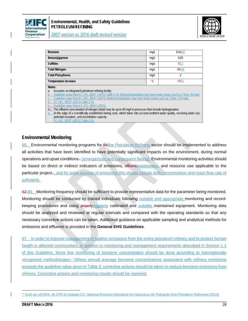
Benzene mg/L 0.0505e
Benzo(a)pyrene mg/L 0.05
Sulfides mg/L 10.2
Total Nitrogen mg/L 10b10f
Total Phosphorus mg/L 2
Temperature increase C <3c3g
Notes: a. Assumes an integrated petroleum refining facility. b. Guideline value from EC JRC, BREF (2015) Table 3.16; National legislations may have lower values such as China: 20 mg/L. c. Guideline value from EC JRC, BREF (2015); National legislations may have lower values such as China: 120 mg/L. d. EC JRC, BREF (2015) Table 3.16. e. Guideline value from EC JRC, BREF (2015). b.f. The effluent concentration of nitrogen (total) may be up to 40 mg/l in processes that include hydrogenation. g. At the edge of a scientifically established mixing zone, which takes into account ambient water quality, receiving water use,
65. Environmental monitoring programs for thisthe Petroleum Refining sector should be implemented to address
all activities that have been identified to have potentially significant impacts on the environment, during normal
operations and upset conditions. (emergencies and consequent flaring). Environmental monitoring activities should
be based on direct or indirect indicators of emissions, effluentswastewater, and resource use applicable to the
particular project. , and for point sources of emissions this should include both concentration and mass flow rate of
pollutants.
62.66. Monitoring frequency should be sufficient to provide representative data for the parameter being monitored.
Monitoring should be conducted by trained individuals following suitable and appropriate monitoring and record-
keeping procedures and using properlyregularly calibrated and suitably maintained equipment. Monitoring data
should be analyzed and reviewed at regular intervals and compared with the operating standards so that any
necessary corrective actions can be taken. Additional guidance on applicable sampling and analytical methods for
emissions and effluents is provided in the General EHS Guidelines.
67. In order to improve management of fugitive emissions from the entire petroleum refinery and to protect human
health in affected communities, in addition to monitoring and management requirements described in Section 1.1
of this Guideline, fence line monitoring of benzene concentration should be done according to internationally
recognized methodologies.17 Where annual average benzene concentrations associated with refinery emissions
exceeds the guideline value given in Table 3, corrective actions should be taken to reduce benzene emissions from
refinery. Corrective actions and monitoring results should be reported.
17 Such as US EPA, 40 CFR 63 Subpart CC- National Emission Standards for Hazardous Air Pollutants from Petroleum Refineries (2015).
Environmental, Health, and Safety Guidelines PETROLEUM REFINING
2007 version vs 2016 draft revised version
DRAFT MARCH 2016 25
WORLD BANK GROUP
Table 3. Fence Line Monitoring Action Level.
Pollutant Guideline Value
Benzene 9 µg/m3 a
a. Annual average concentration that is corrected for background contribution. Guideline value from US EPA 40CFR63 Subpart CC—National Emission Standards for Hazardous Air Pollutants from Petroleum Refineries (2015).
Resource Use, Energy Consumption, Emission and Waste Generation
63.68. Tables 34 and 45 provide examples of resource consumption, and emission / /waste quantities generated
per million tons of processed crude oil. Industry benchmark values are provided for comparative purposes only and
individual projects should target continualcontinuous improvement in these areas.
Environmental, Health, and Safety Guidelines PETROLEUM REFINING
2007 version vs 2016 draft revised version
DRAFT MARCH 2016 26
WORLD BANK GROUP
Table 34. Resource and Energy Consumption1Consumption
Parameter Definition of Parameter
Unit Industry Benchmark
Land Use (1) hectares 200-500
Total Energy Consumption(1)
Total energy consumed by the process, including direct combustion, steam, electricity, etc.
MJ per Metric Tontonne of processed crude oil
2,100 – 2,900
300–3,300
Electric Power Consumption(1)(2) )
Total electricity consumed by the process
kWh per Metric Tontonne of processed crude oil
25 - 48
22–31
Fresh Make-up Water(2)
The supply of raw filtered water which integrates drift and evaporation losses as well as blowdown.
m3 per Metric Tontonne of processed crude oil
0.07 – –0.1466
Notes: 1. Based in part on EC BREF for Refineries 1. Greenfield facilitiesBased on CONCAWE, EU refinery energy systems and efficiency, Report No. 3/12. (2012);
CONCAWE, Oil Refining Report No. 1/13 (2013); US Energy Information Administration (EIA), Short Term Energy Outlook (2013).
1.2. Based on EC JRC, “BREF Document for the Refining of Mineral Oil and Gas” (2015).
Table 45. Emission and Waste Generation1Generation
Parameter Unit Industry Benchmark
WastewaterWaste water Tons / million tons of processedm3/tonne crude oil 0.1 - 5–1.51
Notes: 1. Based in part on EC BREF for Refineries Based on European Commission Joint Research Center (EC JRC), “Best Available Techniques Reference (BREF)
Document for the Refining of Mineral Oil and Gas” (2015). 2. Not all GHGs, only total CO2. Based on EC JRC, “BREF Document for the Refining of Mineral Oil and Gas” (2015). 3. NO+NO2 expressed in NO2 equivalent. 1.4. SO2+SO3 expressed in SO2 equivalent.
Environmental, Health, and Safety Guidelines PETROLEUM REFINING
2007 version vs 2016 draft revised version
DRAFT MARCH 2016 27
WORLD BANK GROUP
2.2 Occupational Health and Safety
Occupational Health and Safety Guidelines
64.69. Occupational health and safety performance should be evaluated against internationally published
exposure guidelines, of which examples include the Threshold Limit Value (TLV®) occupational exposure
guidelines and Biological Exposure Indices (BEIs®) published by the American Conference of Governmental
Industrial Hygienists (ACGIH),18 the Pocket Guide to Chemical Hazards published by the United States National
Institute for Occupational Health and Safety (NIOSH),19 Permissible Exposure Limits (PELs) published by the
Occupational Safety and Health Administration of the United States (OSHA),20 and Indicative Occupational
Exposure Limit Values published by European Union member states,21 or other similar sources.
Accident and Fatality Rates
65.70. Projects should tryendeavor to reduce the number of accidentsincidents and near misses among project
workers (whether directly employed or subcontracted) to a rate of zero, especially accidentsincidents that could result
in lost work time, different levels of disability, or even fatalities. Facility rates may be benchmarked against the
performance of facilities in this sector in developed countries through consultation with published sources (e.g.., US
Bureau of Labor Statistics and UK Health and Safety Executive)).22.
Occupational Health and Safety Monitoring
66.71. The working environment should be monitored for occupational hazards relevant to the specific project.
Monitoring should be designed and implemented by accredited professionals23 as part of an occupational health
and safety monitoring program. Facilities should also maintain a record of occupational accidents and diseases and
dangerous occurrences and accidents. Additional guidance on occupational health and safety monitoring programs
is provided in the General EHS Guidelines.
18 http://www.acgih.org/TLV/18/, available at: http://www.acgih.org/TLV/http://www.acgih.org/TLV/ and http://www.acgih.org/store/http://www.acgih.org/store/. 19 Available at: http://www.cdc.gov/niosh/npg/ http://www.cdc.gov/niosh/npg/. 20 Available at: http://www.osha.gov/pls/oshaweb/owadisp.show_document?p_table=STANDARDS&p_id=9992 Available at http://www.osha.gov/pls/oshaweb/owadisp.show_document?p_table=STANDARDS&p_id=9992. 21 Available at: http://europe.osha.eu.int/good_practice/risks/ds/oel/ Available at http://europe.osha.eu.int/good_practice/risks/ds/oel/. 22 Available at: http://www.bls.gov/iif/ and http://www.hse.gov.uk/statistics/index.htm Available at http://www.bls.gov/iif/ and http://www.hse.gov.uk/statistics/index.htm. 23 Accredited professionals may include Certified Industrial Hygienists, Registered Occupational Hygienists, or Certified Safety Professionals or their equivalent.
Environmental, Health, and Safety Guidelines PETROLEUM REFINING
2007 version vs 2016 draft revised version
DRAFT MARCH 2016 28
WORLD BANK GROUP
3.0 References and Additional SourcesAmerican Petroleum Institute (API). 20032008. Recommended Practice: (RP) 2003. “Protection Against Ignitions Arising out of Static, Lightning, and Stray Currents..” Seventh edition. Washington, DC: API. Available at http://publications.api.org.
API. 1999. API Publication 2218. Fireproofing Practices———2012. Recommended Practice (RP) 2001. “Fire Protection in Petroleum and
Petrochemical Processing Plants. Second Edition, August 1999.Refineries.” Washington, DC: API.
API. 1998. API Standard 650. Welded Steel Tanks for Oil Storage. Third Edition, November 1998. Washington, DC: API.
API. 1997. Manual of Petroleum Measurement Standards, Chapter 19 – Evaporative Loss Measurement, Section 2 - Evaporative Loss from Floating-Roof Tanks. Second Edition. Formerly API Publications 2517 and 2519. Washington, DC: API.
API. ———1992. Recommended Practice (RP) 751. “Safe Operation of HydrochloricHydrofluoric Acid Alkylation Units.
First.” Third Edition, June 1992. Washington, DC: API.2007. Washington, DC: API. Available at http://www.api.org/environment-health-and-safety/process-safety/process-safety-standards/standard-rp-751.
Conservation of Clean Air and Water in Europe (CONCAWE). 1999. “Best Available Techniques to Reduce Emissions from Refineries..” Brussels: CONCAWE.
———2009. “Refining BREF Review. Air Emissions.” Report No. 4/09. Brussels: CONCAWE. Available at https://www.concawe.eu.
———2012. “EU Refinery Energy Systems and Efficiency.” Report No. 3/12. Brussels: CONCAWE. Available at https://www.concawe.eu.
———2013. “Oil Refining.” Report No. 1/13. Brussels: CONCAWE. Available at https://www.concawe.eu.
European Commission. (EC). 2003. European Integrated Pollution Prevention and Control Bureau (EIPPCB). “Best Available Techniques (BAT) Reference (BREF) Document for Refineries. (BREF).” Seville: EIPPCB. Available at
http://eippcb.jrc.es/pages/FActivities.htm Available at http://eippcb.jrc.ec.europa.eu/reference/.
German Federal Ministry for the Environment, Nature Conservation and Nuclear Safety (BMU). 2004. Waste Water Ordinance – AbwV. (Ordinance on Requirements for the Discharge of Waste Water into Waters).EC Joint Research Center (JRC). 2015. ‘Best Available Techniques Reference (BREF) Document for the Refining of Mineral Oil and Gas”. Available at http://eippcb.jrc.ec.europa.eu/reference/.European Union (EU). “Directive 2008/50/EC of the European Parliament and of the Council of 21 May 2008 on Ambient Air Quality and Cleaner Air for Europe.” Brussels/Strasbourg: European Union.
Promulgation of the New Version of the Waste Water Ordinance of 17 June 2004. Berlin: BMU. Available at http://www.bmu.de/english/water_management/downloads/doc/3381.php
German Federal Ministry for the Environment, Nature Conservation and Nuclear Safety (BMU). 2002. “First General Administrative Regulation Pertaining to the Federal Emission Control Act (Technical Instructions on Air Quality Control – TA Luft).).” Berlin: BMU. Available at http://www.bmu.de/english/air_pollution_control/ta_luft/doc/36958.phphttp://www.bmu.de/english/air_pollution_control/ta_luft/doc/36958.php.
———2004. “Waste Water Ordinance – AbwV. (Ordinance on Requirements for the Discharge of Waste Water into Waters).” Promulgation of the New Version of the Waste Water Ordinance of 17 June 2004. Berlin: BMU. Available at http://www.bmu.de/english/water_management/downloads/doc/3381.php.
Environmental, Health, and Safety Guidelines PETROLEUM REFINING
2007 version vs 2016 draft revised version
DRAFT MARCH 2016 29
WORLD BANK GROUP
IFP Energies Nouvelles. Water in Fuel Production, Oil Production, and Refining. Rueil-Malmaison Cedex – France. Available at www.ifpenergiesnouvelles.com.
Intergovernmental Panel on Climate Change (IPCC),). 2006. Special Report, . “Carbon Dioxide Capture and Storage.
.” Geneva: IPCC. Available at http://www.ipcc.ch/http://www.ipcc.ch/.
Irish Environmental Protection Agency (EPA). 1992. BATNEEC Guidance Note. Class 9.2. “Crude Petroleum Handling and Storage..” Dublin: Irish EPA. Available at http://www.epa.ie/Licensing/BATGuidanceNotes/http://www.epa.ie/Licensing/BATGuidanceNotes/.
Maheu, A. 2009. Energy Choices and Their Impacts on Demand for Water Resources: An Assessment of Current and Projected Water Consumption in Global Energy Production. McGill University.
Meyers, Robert. A. 1997. Handbook of Petroleum Refining Processes. New York, NY: McGraw-Hill Handbooks.
Italian Ministry of the Environment (Ministero dell'Ambientedell’Ambiente). 1999. Servizio Inquinamento Atmosferico e Acustico e le Industrie a Rischio. Italian Refining Industry. Rome: Ministero dell'Ambientedell’Ambiente.
UNESCO. 2008. IHE “Water Footprint of Bio-Energy and Other Primary Energy Carriers.”
University of California,. 2005. Ernest Orlando Lawrence Berkeley National Laboratory. “Energy Efficiency Improvement and Cost Saving Opportunities for Petroleum Refineries. Available at.” Available at: http://repositories.cdlib.org/cgi/viewcontent.cgi?article=3856&context=lbnlhttp://repositories.cdlib.org/cgi/viewcontent.cgi?article=3856&context=lbnl.
United States (US) Environmental Protection Agency (EPA). 40 CFR Part 60 “Standard of Performance for New Stationary Sources..” Subpart Kb——“Standards of Performance for Volatile Organic Liquid Storage Vessels (Including Petroleum Liquid Storage Vessels) for Which Construction, Reconstruction, or Modification Commenced after July 23, 1984..” Washington, DC: US EPA. Available at http://www.epa.gov/epacfr40/chapt-
I.info/http://www.epa.gov/epacfr40/chapt-I.info/.
US EPA, ———40 CFR Part 60 “Standard of Performance for New Stationary Sources..” Subpart J——“Standards of Performance for Petroleum Refineries..” Washington, DC: US EPA. Available at http://www.epa.gov/epacfr40/chapt-
I.info/http://www.epa.gov/epacfr40/chapt-I.info/.
US EPA., 40 CFR Part 60 Standard of Performance for New Stationary Sources. Subpart QQQJa—Standards of Performance for Petroleum Refineries for Which Construction, Reconstruction, or Modification Commenced After May 14, 2007. Washington, DC: Available at http://www3.epa.gov/ttn/atw/petref.html ———40 CFR Part 60 “Standard of Performance for New Stationary Sources.” Subpart QQQ—“Standards of Performance for VOC Emissions From Petroleum Refinery Wastewater Systems..” Washington, DC: US EPA. Available at http://www.epa.gov/epacfr40/chapt-I.info/ http://www3.epa.gov/ttn/atw/petref.html
US EPA. ———40 CFR Part 63. Subpart CC——“National Emission Standards for Hazardous Air Pollutants from Petroleum Refineries..” Washington, DC: US EPA. Available at http://www.epa.gov/epacfr40/chapt-I.info/ http://www3.epa.gov/ttn/atw/petref.html
US EPA. ———40 CFR Part 63. Subpart VV——“National Emission Standards for Oil-Water Separators and Organic-Water Separators..” Washington, DC: US EPA. Available at http://www.epa.gov/epacfr40/chapt-
I.info/http://www.epa.gov/epacfr40/chapt-I.info/.
Environmental, Health, and Safety Guidelines PETROLEUM REFINING
2007 version vs 2016 draft revised version
DRAFT MARCH 2016 30
WORLD BANK GROUP
US EPA, ———40 CFR Part 419. “Petroleum Refining Point Source Category..” Washington, DC: US EPA. Available at http://www.epa.gov/epacfr40/chapt-I.info/ http://water.epa.gov/scitech/wastetech/guide/petroleum/
US EPA, “Emissions Estimation Protocol for Petroleum Refineries” (2015). Available at http://www3.epa.gov/ttn/chief/efpac/protocol/index.html
US EPA, “Compilation of Air Pollutants Emission Factors- AP42, Fifth Edition” (1995)United States (US) Energy Information Administration (EIA). 2011. Annual Energy Review 2010. DOE/EIA-0384(2010). Washington, DC.. Available at http://www.eia.gov/.
———2010. Petroleum Supply Annual 2009. DOE/EIA-0340(2009)/1. Washington, DC.. Available at http://www.eia.gov/.
———2011. Petroleum Supply Annual 2010. DOE/EIA-0340(2010)/1. Washington, DC. Available at http://www.eia.gov/.
———AEO2012 National Energy Modeling System run REF2012.D020112C. Available at http://www.eia.gov/.
———“Short Term Energy Outlook.” May 2013. Available at http://www.eia.gov/.
US National Fire Protection Association (NFPA). 2003. Code 30: “Flammable and Combustible Liquids..” Quincy, MA: NFPA. Available at http://www.nfpa.org/http://www.nfpa.org/.
World Refining Association. 1999. “Efficient Operation of Refineries in Western and Central Europe. Improving Environmental Procedures and Energy Production..” Vienna: Honeywell.
Environmental, Health, and Safety Guidelines PETROLEUM REFINING
2007 version vs 2016 draft revised version
DRAFT MARCH 2016 31
WORLD BANK GROUP
Annex A: General Description of Petroleum Industry Activities
67.72. The EHS Guidelines for Petroleum Refining cover processing operations from crude oil to finished, refined,
gaseous, liquid, and solid commercial products and by-products, including refinery fuel gas, liquefied petroleum gas
ether (TAME), or ethanol, butane, etc.) diesel oil pool, LPG pool, among others, and have varying compositions
dependentdepending on the configuration of the refinery process.
68.73. Petroleum refineries are complex systems designed specifically designed based onto produce the desired
products andbased on the properties of the crude oil feedstock. Refineries may range from medium-integrated
refineries to fully integrated refineries (or total conversion refineries), based on the use of different processing units.
Modern refineries incorporate different processing units, capable of either high conversion percentages (coking
refineries), medium conversion (cracking refineries), or low conversion (the old fashioned hydro-skimming
refineries), and are able to process different types of crude oil feed stocks (light, medium, heavy, paraffinic, aromatic,
naphthenic (or cyclo-paraffinic)) with differing sulfur content, high density, high viscosity, high pour point, etc. An
indication of a refinery’s complexity can be assessed with the Nelson Complexity Index (NCI); for instance, an oil
refinery with a high NCI (6<NCI<9), representing the secondary conversion capacity relative to the primary
distillation capacity, is capable of producing high-quality refined products (i.e., Euro 5-grade gasoline), even when
fed with heavy and sour crudes.
69.74. The refinery feedstock is crude oil, which is a mixture of hydrocarbon compounds.24 The hydrocarbons in
crude oil are a mixture of three chemical groups, including paraffins (normal and isoparaffinsiso-paraffins),
naphthenes, (or cyclo-paraffins), and aromatics. The most common distinction between crude oil types is
‘sweet’“sweet” or ‘sour’.“sour.” Sweet crude oil is normally low in sulfur content and lightly paraffinic. Sour crude oil is
usually high in sulfur (more than 0.5 wt percent by weight) and heavily naphthenic. Crude oils are also classified into
light, medium, and heavy, dependent on their content of paraffins, naphthenics, and aromatics.
24 The hydrocarbon mixture may involve different chemical composition and molecular structures, with some impurities. Most of these impurities, such as sulfur (largely in the form of organic compounds such as mercaptans and sulfides), nitrogen, vanadium, and nickel are chemically bound to the hydrocarbon structures. Others, such as sand/clay, water, and water-soluble salts of zinc, chromium, and sodium are present as inorganic material.
Environmental, Health, and Safety Guidelines PETROLEUM REFINING
2007 version vs 2016 draft revised version
DRAFT MARCH 2016 32
WORLD BANK GROUP
Process Units
Desalting
70.75. Desalting is a process to washthat involves washing the crude oil with fresh, brackish, or even sea water at
a high temperature and, using pressure to dissolve, separate, and remove the salts, water, and solids. originally
included in the raw crude. The washing water—generally pumped in counter-current through one or more desalting
stages—displaces the equilibrium of salts (electrolytic components, as water), from the crude feed stream to the
aqueous phase, namely the washing water, aided by carefully modulated electrostatic fields. Crude oil and/or
reduced crude (commonly referred to as oily feedstock) and freshwashing water are the inputsinput streams to the
desalting unit, and washed, dehydrated, and desalted crude oil and, as the contaminated oiled water, are its
outputsoutput streams. The salts containing some of the metals that can poison catalysts are dissolved in the water
Environmental, Health, and Safety Guidelines PETROLEUM REFINING
2007 version vs 2016 draft revised version
DRAFT MARCH 2016 33
WORLD BANK GROUP
phase. After the oil has been washed and mixed as an emulsion of oil and water, de-emulsifying chemicals are then
added and electrostatic fields are used to break the emulsion.
Primary Distillation Units
71.76. These units include the Atmospheric Distillation Unit (Topping or Crude Distillation Unit (CDU))) followed by
the Vacuum Distillation Unit (HVUVDU). Desalted crude oil is fed to a distillation tower working at atmospheric
pressure where the various fractions composing the crude oil are separated according to their boiling range. The
heaviest fractions recovered at CDUthe bottom of the CDU (atmospheric residue) do not vaporize under the tower
atmospheric pressure, and require further fractionation under vacuum conditions in the vacuum distillation tower;
otherwise they would be subject to thermal degradation, due to extremely high boiling temperatures, if submitted to
atmospheric distillation. The major benefits of VDU are the increased recovery of quantities of distillates (vacuum
gas oils, vacuum distillates, and waxes) from the heavy residue of the atmospheric distillation.
Bitumen Production Unit
72.77. The Bitumen Production Unit is fed with vacuum residue. In the Bitumen Blowing Unit (BBU), also called
the Bitumen Oxidation Unit, air is blown into the hot bitumen, which causes dehydrogenation and polymerization
reactions and yields. This creates a harder product with higherincreased viscosity, a higher softening point, and
reduced penetration, making the bitumen suitable for a range of applications, such as paving for roads. The blown
bitumen is removed from the bottom of the oxidation vessel and cooled before being sent to storage. Bitumen is
typically stored at 150–180°C in heated, insulated and nitrogen blanketed cone-roof tanks fitted with safety valves. These
tanks are internally heated, insulated, and nitrogen blanketed. The nitrogen discharged into theto atmosphere may
contain hydrocarbons and sulfur compounds in the form of aerosol-containing liquid droplets.
Hydrogen Consuming Processes
78. The products from the CDUs and the feeds to other units contain some natural impurities, such as sulfur,
nitrogen, and other contaminants. Using the hydrotreating process, these impurities can be removed to reduce
pollution when finished fuels (gasoline, diesel, fuel oils) are used and combusted. Hydrofinishing is used to modify
other properties (i.e., aromatic content) as well. Heavy oils, high in sulfur and nitrogen, also require treatment prior
to being fed to downstream catalytic conversion processes.
79. Hydrotreating (Hydrodesulfurization & Hydrodenitrogenation) are catalytic processes using hydrogen to
perform a very mild hydrogenation of sulfur and nitrogen in hydrocarbons. In this process, sulfur and nitrogen are
converted into hydrogen sulfide (H2S) and ammonia (NH3). The catalytic reaction (Co and/or Ni-Mo catalysts) occurs
from 370°C to 415°C; at higher temperatures, too much coke would form and catalyst life between regenerations
would be too short. Naphtha, jet fuel, diesel, gas oil, lube oil, and fuel oil can all be treated in this way to remove
deleterious substances.
Environmental, Health, and Safety Guidelines PETROLEUM REFINING
2007 version vs 2016 draft revised version
DRAFT MARCH 2016 34
WORLD BANK GROUP
73. Sulfur Hydrotreating25 and hydro-processing processes, such as the Hydrodesulfurization of gasoil or
naphtha, are used to remove impurities such as sulfur, nitrogen, oxygen, halides, and traces of metal impurities
that may deactivate and even poison the noble metalsmetal catalysts, such as platinum, palladium, and nickel.
Hydrotreating also upgrades the quality of the processed fractions by converting olefins and di-olefins into
paraffins for the purpose of reducing gum (polyolephins) formation in fuels. Hydroprocessing cracks heavy
molecules into lighter, more saleable products. Both processes are usually placed upstream of process units,
such as the Catalytic Reforming Unit and the Hydrocracking Units,26 in which sulfur and nitrogen could have
adverse effects on catalyst operation. Hydrogen consumption is high and requireskinetics benefits. The global trend
towards extracting heavy crudes from wells at the presenceend of a Hydrogen Plant intheir life cycles means that
refineries require larger and larger hydrogen production plants to cope with the refinery.
74.80. higher sulfur content (as a result of scraping the barrel). Against this background, more stringent regulations
are being enforced concerning the maximum allowable H2S (refined product) or sulfur dioxide (SO2) (combustion
flue gas) concentrations. The C5 – –C6 isomerization units are based on skeletal isomerization processes (e.g. ‘.,
“once-through’through” and ‘recycle’“recycle” types), used to convert a linear molecule into a branched one with the
same raw formula. Typically, low molecular weight normal paraffins (C4-–C6) are converted into isoparaffinsiso-
paraffins, which have a much higher octane indexnumber. There are three distinct different types of catalysts currently
in use, including chloride-promoted catalysts, zeolites, and sulfated zirconium catalysts.
75.81. The dienes hydrogenation and butylenes hydroisomerization unit is placed upstream of the alkylation
process and is based on a highly selective catalytic process. This process hydrogenates acetylenes and dienes
into the corresponding mono-olefins, without affecting the valuable olefin content of the feedstock, while converting
linear butene-1 into linear butenes butene-2, which, in alkylation, leads to higher-octane gasoline components than
those derived from butene-1.
Pretreating and Catalytic Reformer Unit
76.82. The typical feedstocks are heavy virgin naphtha (HVN) from the crude distillation unitCDU and, when
applicable, the hydrotreated heavy naphtha from the hydrocracker unit. Naphtha feed, mixed with a hydrogen-rich
gas stream, is heated and vaporized and then fed into the hydrotreater reactor (pretreating), which contains a fixed
bed of cobalt / /nickel / /molybdenum catalyst. The C5-minus hydrocarbons contained in the product, after the
25 The hydrotreating process can be divided into a number of reaction categories: naphtha hydrotreating (or pretreating, where upstream of reforming), hydrodesulfurization (HDS, including Middle Distillate Hydrodesulfurization Unit, Selective Catalytic Hydrodesulfurization, and Diesel Oil Deep Hydrodesulfurization), selective hydrocracking (or dewaxing), hydrodenitrification, saturation of olefins and saturation of aromatics, residue hydrotreating. 26 The Hydrocracking Unit is one of the most versatile of all refining processes, capable of converting any fraction, from atmospheric gas oils to residual (de-asphalted) oil, into products with a molecular weight lower than that of the feed. The Hydrocracking reactions occur under high hydrogen partial pressure in catalytic reactors at a substantially high pressure (35 to 200 bar) and at temperatures between 280 and 475ºC. The catalyst (Co/Ni/Mo based) has a two-fold function: hydrogenation and cracking. The most common types of reactor technologies applied are Fixed Bed and Ebullated Bed. The selection of the type of technology is predominantly determined by the metal content in the feed.
Environmental, Health, and Safety Guidelines PETROLEUM REFINING
2007 version vs 2016 draft revised version
DRAFT MARCH 2016 35
WORLD BANK GROUP
separation of hydrogen, are removed in a stripping tower. The heavy naphtha, free from nitrogen and sulfur
compounds, leaving the hydrotreating section, enters the Catalytic Reformer Section to be upgraded for use as
high-octane gasoline blend -stock.
77.83. There are four major types of reactions whichthat occur during the reforming process: (1) dehydrogenation
of naphthenes to aromatics; (2) dehydrocyclization of paraffins to aromatics; (3) isomerization; and (4)
hydrocracking. There are several catalytic reforming processes in use and they can be classified into three
categories, including ‘continuous’,“continuous”, which makes use of moving-bed reactors, as well as ‘cyclic’“cyclic” and
‘“semi-regenerative’,regenerative”, both making use of fixed-bed reactors. The Semi-Regenerative Catalytic
Reformer (SRCR) is typically comprised of three reactors, each with a fixed bed of catalyst. All of the catalyst is
regenerated in situ during routine catalyst regeneration, which occurs approximately once every six to 24 months.
The Continuous Catalyst Regeneration Reformer (CCRR) is characterized by continuous in-situ regeneration of
part of the catalyst in a special regenerator, and by continuous addition of the regenerated catalyst to the operating
reactors. Coke deposits on the catalyst cause a decline in activity, with a reduction of octane number and reformate
yield. The catalyst is regenerated by admitting hot air to remove the carbon from the catalyst, forming carbon
monoxide (CO) and dioxide (CO2), followed by chlorination. The high temperature required for regeneration causes
the catalyst’s pores to collapse. Consequently, every two to three years the entire reformer must be shut down for
catalyst change out. In the CCRR, the major benefits may be summarized as follows: high conversion of olephins
into paraffins, which are then reformed to a high-octane number value component for Mo-Gas blending, in
conformity with the production of gasoline featuring the European Quality mark (EURO V). Other favorable benefits
are a strong reduction of sulfur concentration from motor fuels, an increase in RON of heavy naphtha and significant
hydrogen resources for hydrotreating units, resulting from dehydrogenation reactions, typical of catalytic reforming.
Catalytic Cracking Units (Catcrackers)
78.84. Catalytic cracking is by far the most widely used conversion process to upgrade heavy hydrocarbons into
the more valuable lower-boiling hydrocarbons. It makes use of both heat and catalyst to break the large hydrocarbon
molecules into smaller, lighter molecules. Unlike the hydrocracker unit, no hydrogen is used and, consequently,
limited desulfurization takes place during the process. Catalytic cracking designs include moving-bed reactors,
fluidized-bed reactors (e.g.., Fluid Catalytic Cracking Unit [(FCCU],), Residue Catalytic Cracking Unit
[(RCCU]),)), and once-through units. The FCCU feed stream is the desulfurized heavy vacuum gasoil coming from
hydrocracking. RCCU treats heavier feedstocks, such as the atmospheric distillation residue.
79.85. In both processes, oil and vapor are contactedcome into contact with a hot catalyst in the ‘“Riser
Reactor’.Reactor.” The cracking process takes place in the presence of a zeolite-type catalyst. The fluidized catalyst
and the reacted hydrocarbon vapor separate mechanically in a cyclone system and any oil remaining on the catalyst
is removed by feeding steam in the stripping section of the reactor. The catalytic cracking processes
Environmental, Health, and Safety Guidelines PETROLEUM REFINING
2007 version vs 2016 draft revised version
DRAFT MARCH 2016 36
WORLD BANK GROUP
produceproduces coke. This is deposited on the catalyst surface, thereby reducing activity and selectivity. Catalysts
should be continuously regenerated, essentially by burning off the coke from the catalyst at high temperature in the
regenerator. Products are separated by means of a fractionation train. Current catalytic cracking processes are all
fluidized bed processes (FCC) using powder catalysts (20–50 microns). Regeneration takes place continually, with
some of the catalyst being sent from the reactor to the regenerator, and then from the regenerator to the reactor.
Typical feedstocks of an FCC are; Vacuum Gas Oil, Atmospheric Gas Oil, Atmospheric Resid, Vacuum Resid,
Coker Gas Oil, Visbreaker Gas Oil, Deasphalted Oil. Typical products are gasoline, diesel oil, light fuel oils, and
olefin-rich gases.
86. The FCCU is one of the major sources of air emissions within a refinery. Air emissions are associated mainly
from the regenerator and are CO, CO2, NOX, particulates (mainly catalyst fines including their constitutive heavy
metals) and SO2.
Gas Plant Units
80.87. Low-boiling hydrocarbons are usually treated in a common separation plant operating at elevated pressure.
Gas plants allow recovery and separation by distillation of C1 - –C5 hydrocarbons and higher compounds from the
various refinery off-gases. The gas plant consists of a fractionation train where the following streams are separated:
C1-–C2 fraction; C3 fraction (propane); C4 fraction (butane); and debutanized gasoline. Amine Treating Units
remove hydrogen sulfideH2S and carbonyl sulfide (COS) from all product streams. Before being sent to the relevant
storages, liquid products pass through to Sweetening Units based on selective adsorption on molecular sieves.
Etherification Units
81.88. The feedstocks of methyl tertiary butyl ether (MTBE/)/ethyl tertiary butyl ether (ETBE) units are the C4
hydrocarbons stream coming from the FCCU, and methanol (CH4O) or ethanol. (C2H6O). Isobutylene reacts with
methanolCH4O or ethanolC2H6O to yield directly MTBE (methyl-tert-butyl-ether) or ETBE (ethyl-tert-butyl-ether), respectively.
The reactors can be of the adiabatic or tubular type or combined with a fractionation tower (this type of reactor is
normally referred to as a Catalytic Distillation Reactor or Reactor Column). The catalyst is a sulfonic resin. The
feedstock of TAME units is in light cracked naphtha (LCN, (), composed of C5 hydrocarbons, both paraffins and
olefins).. However, only the reactive isoamylenesiso-amylenes (2-methyl-butene-1 and 2-methyl-butene-2) react with
methanolCH4O to directly yield TAME (tert-amyl-methyl-ether).. Adiabatic-type reactors are used, and the catalyst is the
same as for the MTBE / /ETBE units. Oxygenates, such as MTBE, ETBE, and TAME, were used originally simply
as an additive to improve octane number. However, because of their oxygen content, they are now also added to
reduce the CO and hydrocarbon in the emission gases.
Environmental, Health, and Safety Guidelines PETROLEUM REFINING
2007 version vs 2016 draft revised version
DRAFT MARCH 2016 37
WORLD BANK GROUP
Alkylation Units
89. The purpose of the alkylation unit is to produce a high-quality gasoline blending component called alkylate.
Alkylation is the reactioncombines low-molecular-weight olefins (primarily a mixture of C3propylene and C4
olefinsbutylene) with isobutaneiso-butane in the presence of a catalyst, either sulfuric acid or hydrofluoric acid (HF), to
form higher-molecular-weight isoparaffins with a high-octane number (preferably iso-octane).The product (alkylate)
is composed of a mixture of high-octane, branched-chain paraffinic hydrocarbons. Alkylate is a premium blending
stock (RON up to 98). The octane number of the alkylate depends on the type of olefins used, as well as on operating
conditions.
82. The process involves low-temperature reaction conditions conducted in the presence of very strong acids
(hydrofluoric acidHF or non-fuming sulfuric acid). The reaction in hydrofluoric acidHF alkylation produces acid soluble
oil (normally referred to as ASO) which, after neutralization, is burned in a furnace by means of a dedicated
burner. The reaction in sulfuric acid alkylation produces acid sludges (spent acid), which are burned to recover
sulfuric acid (sulfuric acid regeneration).
83.90. The acid sludges are fed into a decomposition) in a furnace together with fuel gas, where, at 1,050°C, the
decomposition of the sulfuric acid into sulfur dioxideSO2 takes place. The gas leaving the furnace is cooled down to
350*°C in a waste-heat boiler, and then further cooled and filtered. The gas and condensed water are fed to the gas
treatment system.
Polymerization Unit
91. Polymerization is the process by which monomer units are bonded by covalent bonds to generate giant
molecules; a “substance containing high-molecular-weight molecules, consisting of repeating units which are
bonded to each other.”
84.92. In the polymerization process unit, the C3 and C4 olefins are dimerized and oligomerized to produce the
so-called polymeric gasoline as a high-octane blending component. The process is similar to alkylation in its feed
and products, but is often used as a less expensive alternative to alkylation. The reactions typically take place under
high pressure in the presence of a phosphoric acid catalyst adsorbed onto natural silica.
Coking Units
85.93. Coking is a severe thermal cracking process used primarily to reduce refinery production of low-value
residual fuel oils and transform them into transportation fuels, such as gasoline and light and heavy gas oils. As a
part of the process, coking also produces petroleum coke, which is essentially solid carbon, with varying amounts
of impurities and containing 5–6 percent hydrocarbons. Basically, the coking units convert low-value residual
fractions to lighter products of higher commercial value (wet gas, light and heavy gas oil) and petroleum coke. Two
Environmental, Health, and Safety Guidelines PETROLEUM REFINING
2007 version vs 2016 draft revised version
DRAFT MARCH 2016 38
WORLD BANK GROUP
types of coking processes exist: the delayed coking and the fluid coking processes. The flexi-coking process is
similar to fluid coking, but has fully integrated gasification suitable to gasify the fluidized coke in order to produce
coke gas. The hot vapors from the coke drums contain cracked lighter hydrocarbon products, hydrogen sulfideH2S
and ammoniaNH3, and are fed back to the fractionator where these lighter hydrocarbon products can be treated in a
sour gas treatment system. The condensed hydrocarbons are reprocessed, whereas water is re-used for coke drum
quenching or cutting.
94. Cokers have two, four, or eight coke drums; coking heater charge is delivered to one drum while the other
drum/s are sequentially steam stripped, water cooled and decoked. Steam is usually introduced in the heater tubes
to control velocities and thus minimize coke deposition. The chemical reactions of delayed coking are complex,
however three distinct reactions occur: partial vaporization and mild cracking (visbreaking) of the feed as it passes
through the coker’s furnace; cracking of the vapor occurs as it passes through the coke drum; and successive
cracking and polymerization of the liquid trapped in the coke drum occurs until it is converted to vapor and coke.
86.95. In coke removal, when the coke drum in service is filled, it is isolated for safety reasons, steamed to remove
hydrocarbon vapors, cooled by filling with water, opened, drained, and the coke removed. Most industrial plants
use a hydraulic system for the decoking operation: high-pressure water jets, which are lowered into the coke bed
on a rotating drill stem. The coke, which falls from the drum, is collected directly in railroad cars or pumped as liquid
slurry to a stockpile. Then, in order to eliminate all volatile matter, it must be calcinated at about 1,100–1,250°C;
this operation does not reduce the sulfur content. The sulfur contained in the coke is converted in flexicoking
gasifiers, primarily into hydrogen sulfideH2S, and into traces of carbonyl sulfide.COS. The nitrogen contained in the coke
is converted into ammoniaNH3.
Visbreaking Unit
87.96. The Visbreaking Unit is a well-established non-catalytic thermal cracking process that converts atmospheric
or vacuum residues tointo gas, naphtha, distillates, and tar. It uses heat and pressure to break large hydrocarbon
molecules into smaller, lighter molecules. The major benefits are process flexibility, allowing for direct processing
of heavy oil residues, relative simplicity of the technology, and low capital and operating costs. Visbreaking is
characterized by low conversion of petroleum residues, but allows for more than 10 times the reduction of viscosity,
with the additional benefit of producing a standard fuel oil, making it possible to free most of the straight-run vacuum
gasoil.
88.97. The most important factor in controlling the cracking severity should always be the stability and the viscosity
of the so-called visbroken residue, which is fed to the fuel oil pool. In general, an increase in the temperature in or
residence time results in an increase in cracking severity. Increased severity increases gasoline yield and, at the
Environmental, Health, and Safety Guidelines PETROLEUM REFINING
2007 version vs 2016 draft revised version
DRAFT MARCH 2016 39
WORLD BANK GROUP
same time, produces cracked residue (fuel oil) of lower viscosity. However, excessive cracking, however, leads to an
unstable fuel oil, resulting in sludge and sediment formation during storage.
89.98. There are two types of visbreaker operations: coil or furnace cracking and soaker cracking. The gas
produced is fed to an amine treating unit, to remove hydrogen sulfideH2S.
Lube Oil Production Units
90.99. A base oil complex typically consists of a vacuum distillation tower, a deasphalting unit, an aromatic
extraction unit, a dewaxing unit, an optional high-pressure hydrogenation unit, and a hydrofinishing unit to improve
color and stability, to meet product specifications and to remove impurities. A conventional base-oil complex is very
labor intensive, mainly due to its batch operation, the many grades of base oil normally produced, and the
associated intensive product handling operations.
Gas Treatment and Sulfur Recovery Units (SRUs)
91.100. Sulfur is removed from a number of refinery process off-gas streams (sour gas) in order to meet the sulfur
oxides (SOX) emission limits and to recover saleable elemental sulfur. Process off-gas streams, or sour gas, from
the coker unit, FCCU, hydrotreating units, and hydroprocessing units, contain high concentrations of hydrogen
sulfideH2S and carbonyl sulfideCOS, mixed with light refinery fuel gases. Before elemental sulfur is recovered, the fuel
gases (primarily methaneCH4 and ethane) need to be separated from hydrogen sulfideH2S and carbonyl sulfides.COS.
This is typically accomplished by dissolving hydrogen sulfideH2S and carbonyl sulfidesCOS in a chemical solvent. The
solvents most commonly used are amines, such as Monoethanolamine (MEA), diethanolamine (DEA). ), or mono-
di-ethanolamine (MDEA). Dry adsorbent, such as molecular sieves, activated carbon, and iron sponge are also
used.
92.101. In the amine solvent processes conducted in the amine gas treating units, a DEA solution, (or anotherother
weak amine solvent,solution) is pumped to an absorption tower top section where the up flowing acid gases are
contacted in counter-current: H2S and hydrogen sulfide and carbonyl sulfideCOS are dissolved in the solution., as well as
carbon dioxide, if present. The fuel gases, free from hydrogen sulfideH2S and carbonyl sulfideCOS, are removed as
treated, sweetened gaseous streams and sent to the refinery fuel gas network. The amine-hydrogen sulfideH2S and
carbonyl sulfideCOS solution is regenerated by heating and steam stripping to remove the hydrogen sulfideH2S gas
before recycling back to the absorber. Hydrogen sulfideH2S and carbonyl sulfideCOS are sent to the Claus Unit for sulfur
recovery. Air emissionsEmissions to atmosphere from the sulfur recovery units (SRUs) will consist of hydrogen
sulfideH2S, SOX, and NOX in the process tail gas, as well as fugitive emissions.
93.102. The Claus process consists of the partial combustion of the hydrogen sulfideH2S and carbonyl sulfideCOS-rich
gas stream and then of reacting the resulting sulfur dioxideSO2 and unburned hydrogen sulfideH2S in the presence of a
Environmental, Health, and Safety Guidelines PETROLEUM REFINING
2007 version vs 2016 draft revised version
DRAFT MARCH 2016 40
WORLD BANK GROUP
bauxitean aluminum oxide catalyst to produce elemental sulfur. Claus units remove only process sulfur recovery
efficiency is in the range of 90 percent of hydrogen sulfide and carbonyl sulfide, and are followed by other processes to complete(one
catalytic reactor) – 98 percent (three catalytic reactors). Tail Gas Treatment Units (TGTU) allow a further sulfur
removal (recovery (total SRU sulfur recovery efficiency up to 99.5 percent). and over).
103. Air emissions from the SRU typically contain H2S, SOX and NOX. The SRU may also generate process
wastewater that contains H2S, NH3 and amines and residual wastes of spent catalysts.
Sour Water Stripper Unit (SWSU)
94.104. Many process units generate sulfides and ammoniaNH3-contaminated water, normally referred to as sour
water. The Sour Water Stripper Unit (SWSU) permits reusing allows for the reuse of sour water by removing sulfides
and ammoniaNH3. The process operation is complicated by the presence of other chemicals, such as phenol, and
cyanides. SWSU treats sour water from the process unit and removes sour gases. Sour water stripping can be
performed through different technologies. In one-stage stripping, the sour water is counter-currently stripped in a
column by injected steam to remove H2S and NH3. In two-stage stripping, a first stage at low pH (6) improves H2S
removal, while the second stage at high pH (10) improves NH3 removal. Benefits: Treated water can be re-used as
desalter wash water. A two-stage SWS process can reach an overall H2S and NH3 recovery of 98 percent and 95
percent, respectively, associated with a residual concentration of 0.1–10 mg/l and 1–10 mg/l. Generated NH3 can
be used within the refinery.
Hydrogen Plant
95.105. Normally, the feedstock of the hydrogen plant is the methane obtained by the refinery process units, LPG,
or refinery external natural gas, if available. , but hydrodesulfurised naphtha can also be used as steam reformer
feedstock. This unit normally consists of a reformer and producessteam reformer (top- or side-fired furnace), where
the vaporized hydrocarbons feed steam through the tubes containing the catalyst. In its reaction with the steam,
generally at about 40 bar, the catalyst produce a hydrogen – carbon monoxide–CO mixture, referred to as synthetic
gas (syngas). After passing through aan important heat-recovery section, cold syngas enters the shift conversion
reactor where, under an iron- or copper-based catalyst, carbon monoxideCO is reacted with water to yield more
hydrogen and carbon dioxide. The latter is separated in an amine absorption – regeneration unit. A closed drain
system collects and recovers any amine drains and spills, thereby preventing them from being purged into the
WWTU.wastewater treatment unit (WWTU). Most Hydrogen Generation Units (HGU) include also the Pressure
Swing Absorption (PSA) section, where the purified hydrogen increases in concentration, due to the molecular
sieve, retaining higher molecular weight components such as nitrogen, etc.
Environmental, Health, and Safety Guidelines PETROLEUM REFINING
2007 version vs 2016 draft revised version
DRAFT MARCH 2016 41
WORLD BANK GROUP
Chemical Treatment Units
96.106. Chemical treatments are used to achieve certain product specifications. The Extraction Sweetening Units
are designed to reduce the mercaptansmercaptan content of hydrocarbon streams to mitigate odor nuisance and to
reduce corrosivity. These treatments are accomplished by either extraction or oxidation (such as with MEROX,
already used in old-fashioned hydroskimming oil refineries) or both, depending on the treated process stream. The
extraction process removes the mercaptans by caustic extraction, resulting in a lower sulfur content. The
sweetening process causes the mercaptans to be converted into less odorous and less corrosive disulfides, which
remain in the product. As a result, no reduction in the total sulfur content takes place during sweetening and,
consequently, it is only applied to those streams where sulfur content is not a problem.
97.107. The spent caustic scrubbing liquor (spent caustic) coming from the extraction sweetening unit is one of the
most problematic waste streams generated in refineries. This is primarily due to the very high sulfidessulfide
concentration, which makemakes it non suitableunsuitable for direct discharge into the WWTUWWTUs. High levels of
sulfides can also create odor and safety problems when released as a gas.
98.108. In the caustic oxidation unit, the reactive sulfides contained in the spent caustic liquor are oxidized into
soluble thiosulfates, sulfites, and sulfates. The treated stream is then suitable for bio-treatment in the WWTU.
Gasification Units
99.109. The gasification units include coke gasification, hydrocarbons gasification (partial oxidation), and hydrogen
purification (i.e., wet scrubbing, membrane systems, cryogenic separation and pressure-swing adsorption). The
synthetic gas produced by coke gasification contains hydrogen sulfideH2S and carbonyl sulfideCOS, and the gas is
treated in an amine treating unit.
Blending Facilities
100.110. Blending is the final operation in petroleum refining. It consists of mixing the products in various
proportions to meet commercial specifications. Blending can be carried out in-line (using dedicated software, based
on a statistic database of major gasoline parameters, easy and quick to measure online and use for the suitable
proportioning of blending) or in batch-blending tanks, using intermediate run-down tanks.
101.111. Air emissionsEmissions to atmosphere from blending include fugitive VOC(VOCs) from blending tanks,
valves, pumps, and mixing operations.
Environmental, Health, and Safety Guidelines PETROLEUM REFINING
2007 version vs 2016 draft revised version
DRAFT MARCH 2016 42
WORLD BANK GROUP
Auxiliary Facilities
112. Auxiliary facilities at petroleum refineries typically consist of waste water treatment units, blow downWWTUs,
blowdown and flare systems, vapor recovery units (e.g.., thermal oxidation, absorption, adsorption, membrane
separation, and cryogenic condensation), and energy/electricity systems (e.g.., boilers, furnaces, gas turbines).
113. Vapor Flare Systems: The main functions of flare systems are:
The disposal of gas during normal operations;
The disposal of gas during gas processing trips;
To prepare for the repair/maintenance of process equipment;