rsc.li/es-water Environmental Science Water Research & Technology ISSN 2053-1400 Volume 6 Number 7 July 2020 Pages 1753–1942 PAPER Ming Xie et al. Emerging investigator series: engineering membrane distillation with nanofabrication: design, performance and mechanisms
Transcript
rsc.li/es-water
EnvironmentalScience Water Research & Technology
ISSN 2053-1400
Volume 6Number 7July 2020Pages 1753–1942
PAPERMing Xie et al.Emerging investigator series: engineering membrane distillation with nanofabrication: design, performance and mechanisms
EnvironmentalScienceWater Research & Technology
PAPER
Cite this: Environ. Sci.: Water Res.
Technol., 2020, 6, 1786
Received 6th February 2020,Accepted 11th May 2020
DOI: 10.1039/d0ew00100g
rsc.li/es-water
Emerging investigator series: engineeringmembrane distillation with nanofabrication:design, performance and mechanisms†
Rui Huang,ab Zhiquan Liu,c Yun Chul Woo, de Wenhai Luo,fg
Stephen R. Gray h and Ming Xie *a
Anti-fouling and durability are two important parameters that are closely associated with the development
and deployment of membrane distillation (MD). In this study, we reported a nanoimprinted, omniphobic
polytetrafluoroethylene (PTFE) membrane with a hierarchical rough structure for the MD process. A highly
ordered, circular surface pattern was first imparted to a PTFE membrane substrate via a nanoimprint
technique. An ultrathin TiO2 layer was deposited onto the nanoimprinted membrane to create a spherical
hierarchical rough structure via atomic layer deposition as well as an initiator for chemical fluorination of
the membrane. The resultant, nanofabricated membrane exhibited a water contact angle of 155° and a
contact angle above 100° against a range of low surface tension liquids. In addition, the nanofabricated
membrane displayed a high and stable water flux of around 34 L m−2 h−1 for more than 24 hours, and
nearly complete salt rejection with the presence of surfactants. Most importantly, the water flux recovery
rate of the resultant membrane was more than 91.3% after three fouling–cleaning cycles, demonstrating
excellent fouling reversibility. The new strategy proposed here that combines the nanoimprint technique
and superhydrophobic modification sheds light on developing MD membranes with considerable durability
and anti-fouling performance.
1. Introduction
Nowadays, the water crisis has become an increasing concernall over the world due to severe water pollution andfreshwater scarcity.1–3 Although around 70% of the earth iscovered by water, fresh water only accounts for 0.3%.4
Therefore, it is imperative to develop reliable and economictechnologies to treat seawater as an alternative source.Membrane distillation (MD), developed in recent decades, isa promising technology for seawater desalination andparticularly for brine management and zero liquiddischarge.5–7 It is driven by the vapour pressure differenceexisting between porous membrane surfaces, in which onlyvapour molecules are able to pass through the membrane.8
Moreover, the heat energy that drive the MD process couldcome from industrial waste heat.9 Thus, MD is emerging as aviable technology for the desalination of seawater.
Membrane wetting is a primary barrier to widespreadindustrial use of MD, which is caused by partial or complete
a Department of Chemical Engineering, University of Bath, Bath, BA2 7AY, UK.
E-mail: [email protected] School of Environment, Harbin Institute of Technology, Harbin 150090, Chinac Key Laboratory for Water Quality and Conservation of the Pearl River Delta,
Ministry of Education, Institute of Environmental Research at Greater Bay,
Guangzhou University, Guangzhou 510006, ChinadDepartment of Land, Water, and Environment Research, Korea Institute of Civil
Engineering and Building Technology (KICT), 283, Goyang-Daero, Ilsanseo-Gu,
Goyang-Si, Gyeonggi-Do, 10223, Republic of Koreae Department of Civil and Environment Engineering, University of Science and
Technology (UST), 217, Gajeong-Ro, Yuseong-Gu, Daejeon, 34113, Republic of
Koreaf Sustainable Energy Systems Engineering Group, School of Engineering, Macquarie
University, Sydney, NSW, 2109, Australiag Beijing Key Laboratory of Farmland Soil Pollution Prevention and Remediation,
College of Resources and Environmental Sciences, China Agricultural University,
Beijing 100193, Chinah Institute for Sustainable Industries and Liveable Cities, Victoria University,
Melbourne, 8001, Australia
† Electronic supplementary information (ESI) available. See DOI: 10.1039/d0ew00100g
Water impact
Membrane distillation (MD) holds promise for sustainable brine management. To achieve this goal, we presented a facile and green approach for MDmembrane design combining nanofabrication and chemical modification. The resultant MD membrane demonstrated anti-wetting and high foulingreversibility in the treatment of brine waste containing surfactants and foulants.
blocking of pores by liquid-phase water on the feed side.10,11
As a result, membranes for MD are usually fabricated usinghydrophobic polymers, such as polyvinylidene fluoride(PVDF),12 polypropylene (PP),13 and polytetrafluoroethylene(PTFE),14 to prevent wetting. Increasing membrane surfacehydrophobicity could reduce the capillary attraction of waterinto membrane pores, thereby mitigating pore wetting.15
Inspired by the feature of lotus leaves or sharkskin,superhydrophobic membranes were first tailored byconstructing a hierarchical rough structure combined with ahydrophobic surface.16–18 Hydrophobic surfaces with ahierarchical rough structure can provide air pockets thatdecrease the total contact area between the membrane andwater.19 Grafting or depositing low surface energymaterials, such as fluoroalkyl-chains, onto a membranesurface is another common method to increasehydrophobicity.20
Increasing the surface hydrophobicity could, however,exacerbate membrane fouling. Because of stronghydrophobic–hydrophobic interactions, hydrophobic foulantscan easily attach to the hydrophobic membrane surface andenter the membrane pores, hindering vapour trasportation.21
To overcome this contradiction, researchers have developedJanus membranes with asymmetric wettability in more recentyears.22,23 The outermost layer of Janus membranes issuperhydrophilic, and is designed to prevent mass transfer offoulants like micro oil drops. For example, Zhu et al.24
developed a hydrophobic PVDF fibrous membrane substratewith a hydrophilic SiO2/PAN skin layer, demonstrating itsstable performance in the treatment of high-salinity watercontaining a high concentration of lubricating oil.Nevertheless, these Janus membranes are much moredifficult to tailor. Most of them suffer poor vapourtransmission efficiency.22,25 Thus, a simple method toconstruct both anti-wetting and anti-fouling MD membranesfor the efficient desalination is required.
Nanoimprint, a simple and versatile nanofabricationtechnique, has been proposed for membrane fabrication,26,27
which endows membrane surfaces with highly orderedfeatures and thus can mitigate membrane fouling. Ourprevious study has proven that a PTFE membrane with aperiodical line pattern could significantly mitigate membranefouling in the MD process,28 due to significantly lowadhesion force between foulants and the patterned MDmembrane surface. However, the durability of pristine PTFEnanoimprinted membranes was still unsatisfactory.Therefore, combining the nanoimprint technique withsuperhydrophobic modification would have great potential toaddress wetting and fouling problems in the MD process.
Herein, we presented a nanoimprinted, omniphobicmembrane via the nanoimprint technique, atomic layerdeposition and fluorination, with the expectation to mitigateboth membrane wetting and fouling. The fabricatedmembrane had a periodical circle pattern with a hierarchicalrough structure and low surface energy. The morphologiesand chemical properties of the membrane were systematically
characterized. Sodium dodecyl sulfate (SDS) and humic acidwere chosen as the model contaminants to evaluate thedurability and anti-fouling performance of the membrane.The green and facial method used here may be a potentialcandidate for brine management with complex compositionand varying foulants.
2. Materials and methods2.1 Nanofabrication for membrane distillation
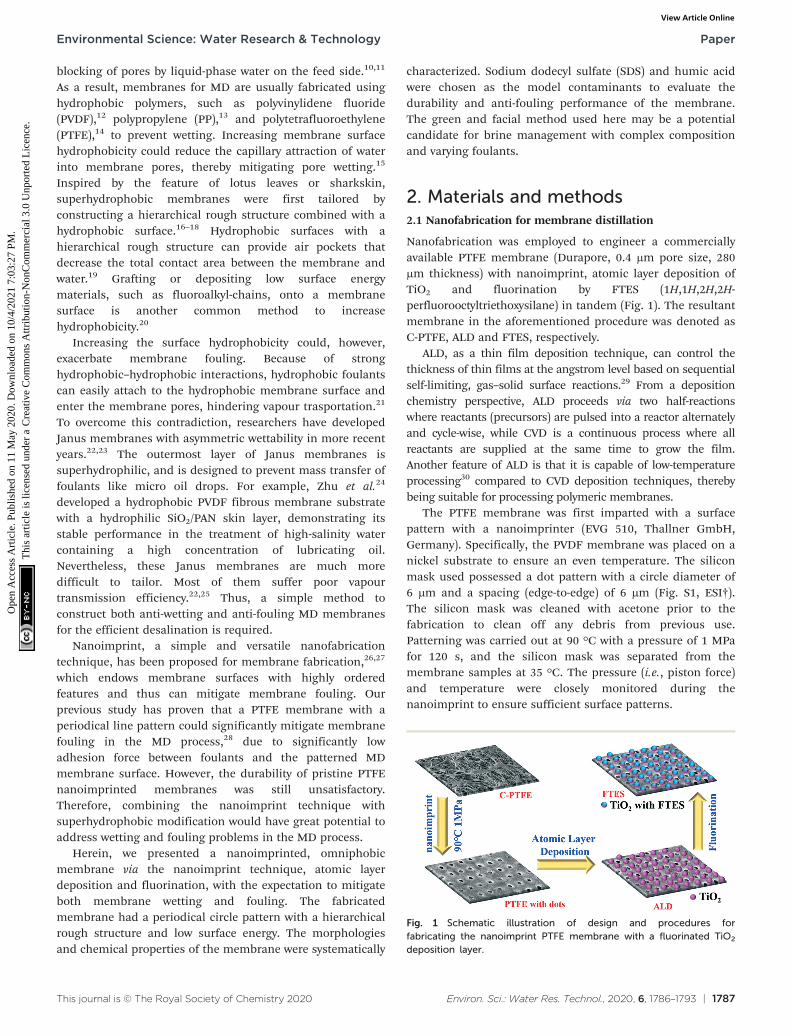
Nanofabrication was employed to engineer a commerciallyavailable PTFE membrane (Durapore, 0.4 μm pore size, 280μm thickness) with nanoimprint, atomic layer deposition ofTiO2 and fluorination by FTES (1H,1H,2H,2H-perfluorooctyltriethoxysilane) in tandem (Fig. 1). The resultantmembrane in the aforementioned procedure was denoted asC-PTFE, ALD and FTES, respectively.
ALD, as a thin film deposition technique, can control thethickness of thin films at the angstrom level based on sequentialself-limiting, gas–solid surface reactions.29 From a depositionchemistry perspective, ALD proceeds via two half-reactionswhere reactants (precursors) are pulsed into a reactor alternatelyand cycle-wise, while CVD is a continuous process where allreactants are supplied at the same time to grow the film.Another feature of ALD is that it is capable of low-temperatureprocessing30 compared to CVD deposition techniques, therebybeing suitable for processing polymeric membranes.
The PTFE membrane was first imparted with a surfacepattern with a nanoimprinter (EVG 510, Thallner GmbH,Germany). Specifically, the PVDF membrane was placed on anickel substrate to ensure an even temperature. The siliconmask used possessed a dot pattern with a circle diameter of6 μm and a spacing (edge-to-edge) of 6 μm (Fig. S1, ESI†).The silicon mask was cleaned with acetone prior to thefabrication to clean off any debris from previous use.Patterning was carried out at 90 °C with a pressure of 1 MPafor 120 s, and the silicon mask was separated from themembrane samples at 35 °C. The pressure (i.e., piston force)and temperature were closely monitored during thenanoimprint to ensure sufficient surface patterns.
Fig. 1 Schematic illustration of design and procedures forfabricating the nanoimprint PTFE membrane with a fluorinated TiO2
deposition layer.
Environmental Science: Water Research & Technology Paper
After nanoimprinting, we deposited an ultrathin layer ofTiO2 (around 5 nm in thickness) on the dot patterned MDmembrane by atomic layer deposition (Fiji F200 ALD,Cambridge Nanotech). TetrakisIJdimethylamino)titanium(Strem Chemicals, Inc., USA), also known as TDMAT, andH2O vapour were used as titanium and oxygen precursors,respectively. An ALD growth cycle of TiO2 depositionconsisted of the following steps and parameters: TDMATpulse 0.1 s, N2 purge 8 s; H2O pulse 60 ms, N2 purge 8 s;deposition temperature at 120 °C. The total cycle of TiO2
deposition was 125, resulting in a TiO2 thickness of around 5nm. The actual thickness of TiO2 was estimated using areference silicon wafer with a variable angle spectroscopicellipsometer (J.A. Woollam M-2000DI).
Utilising the ultrathin film of TiO2 on the dot patternedMD membrane, we further functionalised it with FTES(1H,1H,2H,2H-perfluorooctyltriethoxysilane). Specifically,hydroxylated FTES in toluene was prepared in 50 mL bottlesthrough sonication and vigorous stirring for one hour,respectively. The coating procedure was performed in a glovebox over 18 hours to obtain the resultant membrane, whichwas then washed with toluene and completely dried in anoven prior to use.
2.2 Membrane distillation apparatus and filtration protocol
Direct contact membrane distillation (DCMD) was conductedusing a closed-loop bench-scale membrane test apparatus.The membrane cell was made of acrylic plastic to minimizeheat loss to the surroundings. Flow channels were engravedin each of two acrylic blocks that made up the feed andpermeate semi-cells. Each channel was 0.2 cm deep, 1.5 cmwide, and 1.5 cm long, and the total active membrane areawas 2.25 cm2. Temperatures of feed and distillate solutionswere controlled with two heaters/chillers (Polyscience, IL,USA), and were continuously recorded using temperaturesensors that were inserted at the inlet and outlet of themembrane cell. Both feed and distillate streams wereconcurrently circulated with two gear pumps. The samecrossflow rate of 30 L h−1 (corresponding to the crossflowvelocity of 9 cm s−1) was applied to both feed and distillate inorder to minimize the pressure difference across the MDmembrane. Weight change of the distillate tank was recordedusing an electronic balance (Mettler Toledo, OH, USA) with adata logger. All piping used in the DCMD test unit wascovered with insulation foam to minimize heat loss.
The nanofabricated MD membrane was subjected to bothwetting and fouling experiments. Specifically, MD membranewetting and fouling were simulated with a feed solutioncontaining a 70 g L−1 NaCl solution (simulating seawaterbrine from reverse osmosis) with either 1 mM sodiumdodecyl sulfate (SDS) or 50 mg L−1 humic acid, respectively.In addition, the MD membrane fouling–cleaning cycle wasconducted three times in order to examine the foulingreversibility and cleaning efficiency by physical flushing. Inthe cleaning mode, the humic acid fouled MD membrane
was flushed with DI water at a doubled cross flow rate (i.e.,18 cm s−1) for 20 min. After this brief, physical flushing, thefouling filtration resumed.
Feed and distillate volumes of four litres and one litrewere used, respectively. The temperature of the inlet feedsolution was 60 °C, while that of the distillate inlet streamwas 20 °C in all experiments. A new membrane sample wasused for each experiment. Permeate mass was recorded witha digital balance continuously. The conductivity of thedistillate was measured with a conductivity meter (HQ14d,Hach, CO) every 5 minutes.
2.3 Characterization of the nanofabricated membrane
The nanofabricated MD membrane was comprehensivelycharacterized in order to gain insights into the structure–performance relationship. Scanning electron microscopy(SEM), Fourier transform infrared (FTIR) spectroscopy, X-rayphotoelectron spectroscopy (XPS), atomic force microscopy(AFM) and thermogravimetric analysis (TGA) were employedto analyze the morphology and thermal and physicochemicalproperties of the nanofabricated MD membrane.
Surface and cross-section morphology of the completelydried membranes with gold coating was visualized with an EVOMA 10 (Zeiss, Germany) scanning electron microscope at anaccelerating voltage of 20 kV. AFM images were acquired withan Asylum Research MFP-3D AFM operating in intermittentcontact (“tapping”) mode with a BudgetSensors TAP150Al-Gcantilever ( fR = 123 kHz, Q = 1745 and k = 2.1 N m−1; with free-air amplitude = 100 nm and feedback set-point = 70%).
To obtain information about the composition andbonding chemistry of the MD membrane surface layer (withpenetration depths from 1 to 5 nm thickness), X-rayphotoelectron spectroscopy (XPS) analysis was carried out ona monochromatic aluminium Kα X-ray photoelectronspectrometer (Thermo Scientific, MA). Survey spectra wererecorded 3 times per sample, over the range of 0∼1000 eV at1 eV resolution to analyse the elemental composition.Bonding chemistry of the membrane surface layer wasanalysed by high resolution XPS C1s scan. A spot size of 400μm was used to scan the region of the C1s binding energy at20 eV pass energy. Two random spots on the duplicatemembrane samples were selected. Excessive charging ofsamples was minimized using an electron flood gun. Highresolution scans had a resolution of 0.1 eV. Calibration forthe elemental binding energy was carried out based on thereference for carbon 1 s at 284.6 eV. Data were processedusing standard software with a Shirley background and arelative sensitivity factor of 0.278 for C1s peaks.
Membrane surface functional groups were identified usinga Fourier transform infrared (FTIR) spectrometer (ThermoScientific Nicolet 6700) equipped with an ATR accessoryconsisting of a ZnSe plate (45° angle of incidence).Absorbance spectra were measured with 64 scans of eachsample at a spectral resolution of 2 cm−1. Backgroundmeasurements in air were performed before each membrane
Environmental Science: Water Research & TechnologyPaper
sample measurement. ATR-FTIR spectra were collected at twodifferent spots for each membrane sample.
The membrane contact angle (CA) was measured by thesessile drop method using an optical subsystem (Theta Lite100) integrated with image-processing software. A range of
liquids (water, diiodomethane, ethylene glycol and ethanol)were used for contact angle measurements.31
Thermal properties of the nanofabricated MD membranewere quantified by thermogravimetric analysis (TGA)(Discovery TGA thermogravimetric analyser, SDT-Q600,
Fig. 2 SEM images of the membrane surface: (A) pristine PTFE (C-PTFE); (B) TiO2 atomic layer deposited nanoimprinted membrane (ALD); (C)fluorinated ALD membrane (FTES); (D) cross-section of FTES. Atomic force microscopy (AFM) images of (E) the membrane surface demonstratingthe dot pattern and (F) deposition layer of TiO2.
Environmental Science: Water Research & Technology Paper
United States) from 50 °C to 700 °C at a heating rate of 10 °Cmin−1 in N2 atmosphere. The crucible material was platinum.Each sample was dried by purging N2 for 1 min beforemeasurement.
3. Results and discussion3.1 Characteristics of the nanofabricated MD membrane
3.1.1 Surface and structural characterization of thenanofabricated MD membrane. A commercially availablehydrophobic PTFE membrane was chosen as a scaffold for thesubsequent nanofabrication procedure (Fig. 1). The PTFEmembrane was firstly nanoimprinted and deposited with anultrathin TiO2 layer whose thickness was around 5.56 ± 0.11nm, which was measured from the reference silicon wafer (Fig.S2, ESI†). The fiber-like texture of the PTFE membrane surfacedisappeared, and the membrane surface manifested a periodic,circular surface pattern. Compared with other coatingtechniques, atomic layer deposition can realize a highlyuniform TiO2 layer. As a result, the membrane surface becamesmoother without obvious agglomerated TiO2 nanoparticles.
A close examination of the circular indentation showselongated features in the vertical dimension, exhibitinghierarchical morphology. Besides, the AFM images of theTiO2 deposition membrane (Fig. 2E and F) show the sphericalhierarchical structure, which might lead to specialwettability, thereby being beneficial to MD separation. Afterfluorination, there is no significant difference with the ALDmembrane, only scattered, tiny agglomerated particles couldbe observed. The FTES membrane still maintained a highlyordered dot pattern with a smoother surface (Fig. 2C).
Despite a series of modifications, the PTFE membranewas not compromised as evident in the cross-section of theFTES membrane (Fig. 2D), so the resultant membrane couldbe expected to have a satisfactory NaCl rejection in the MDfiltration. Indeed, the membrane integrity of the modifiedmembrane remains uncompromised, which was evident by a100% NaCl rejection in the MD filtration. To summarize,after the modification, the nanofabricated PTFE membraneexhibited a periodic, circular surface pattern with a sphericalhierarchical structure, and no noticeable difference in themembrane structure was observed.
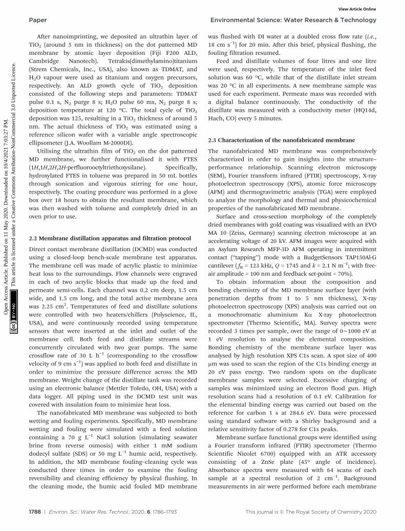
3.1.2 Chemical characterization of the nanofabricated MDmembrane. The surface modification of the PTFE membranewith ALD and FTES was determined by ATR-FTIR and XPS, asshown in Fig. 3A and B. Peak occurrence at wavenumbers of839 and 875 cm−1 (red curve) suggests the bonding of TiO2
nanoparticles onto the membrane via ALD deposition.Reacting with anchoring TiO2 nanoparticles, a fluorosilanesurface modification was initiated involving hydrolysis andcondensation of alkoxysilane groups with hydroxyl functionalgroups of the TiO2 nanoparticles. The completion of thisfluorosilane reaction was evident by the peak occurrence atwavenumbers of 1180 cm−1 and 1234 cm−1, representing theCF2 and CF3 bonds (blue curve). Indeed, the C1 scan of theresultant membrane showed the CF2–CF2 and CF3 bonds on
the membrane surface (Fig. 3B). More importantly, theoccurrence of CF3 bonds corresponds to the characteristicfunctional group possessing low surface energy that isfavorable for MD performance, particularly in the treatmentof streams containing surfactants.
Fig. 3 Chemical characterization of C-PTFE and ALD and FTESmodified membranes. (A) ATR-FTIR spectra; (B) XPS spectra of C1s ofthe FTES modified membrane; (C) TGA curves.
Environmental Science: Water Research & TechnologyPaper
The composition of our modified membranes was furtherstudied by thermogravimetric analysis (TGA). As shown inFig. 3C, the weight of C-PTFE, ALD and FTES remained stablewhen the temperature was below 350 °C. After that, the threemembranes began to lose weight at 375.2 °C (ALD), 385.1 °C(FTES) and 391.1 °C (C-PTFE), respectively. There was aconsistent shift of thermal decomposition towards lowertemperature of the modified membranes (both ALD- andFTES-modified membranes), which indicates enhancementin thermal stability. Higher residual mass was observed forthe ALD modified membrane in comparison with the FTESmodified membrane, indicating that the dispersion of TiO2
nanoparticles in the composite membrane resulted inimproved thermal properties. Another feature presented inthe TGA diagram was that TiO2 deposition on the membranemay catalyse more C-PTFE loss.
3.2 Wetting properties of the nanofabricated MD membrane
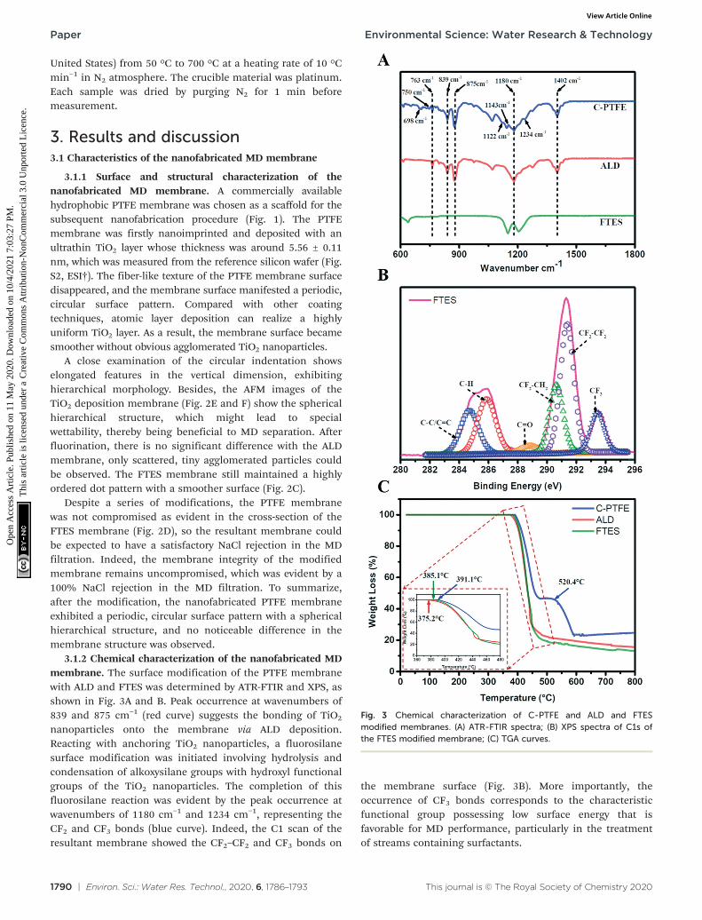
The surface wettability of relevant nanofabricatedmembranes was measured using static water and low surfacetension liquid (diiodomethane, ethylene glycol and ethanol)contact angles as shown in Fig. 4. C-PTFE exhibited a highwater contact angle of 135°, due to its hydrophobic nature.After the TiO2 deposition, the contact angle decreased to112°. TiO2 can produce oxygen vacancies on its surface,which could be occupied by water molecules and produceadsorbed –OH groups. Thus, the membrane coated with TiO2
tended to have a more hydrophilic surface, as demonstratedby a lower WCA. By contrast, the fluorination by FTESendowed ALD with an extremely high water contact angle of155°, thereby rendering a low surface energy as well asmanifesting excellent hydrophobicity.
ALD created a hierarchically rough nanostructure. Basedon the Wenzel and Cassie theory, the establishment of nano/microscale structures was essential for improving thesuperhydrophobicity of a membrane. The contact angles oflow surface tension liquids had the same tendency as waterfor similar reasons. As a result, the superhydrophobic surface
of FTES is expected to have robust stability for MDapplications.
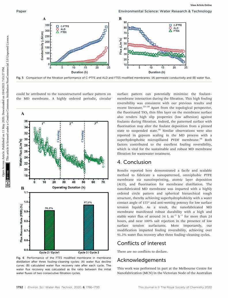
To further examine the role of the fluorinated, hierarchicallyrough, nanostructure membrane surface, we compared thewetting behavior of ALD and FTES membranes to the pristinePTFE membrane using saline feed containing 1 mM SDS.The wetting phenomenon was quantified as the increase ofpermeate conductivity (Fig. 5). It was observed that thepermeate conductivity of the pristine PTFE membrane soaredsharply at the beginning, indicating the occurrence ofmembrane wetting. Although the pristine PTFE membrane isintrinsically hydrophobic, a declining trend in the rejectionof NaCl over time was observed, which was consistent withmembrane wetting during filtration. By contrast, after TiO2
ALD modification, the permeate conductivity maintainedstable for 20 hours. We attribute it to its hierarchically roughnanostructure. Despite the relatively low water contact angle,the hierarchically rough nanostructure could create airpockets on the membrane surface,19 thus mitigatingmembrane wetting. In comparison, the FTES modifiedmembrane was able to sustain the MD performance. Thenanofabricated surface achieved by fluorination and thehierarchically rough nanostructure could successfullypreserve a metastable Cassie–Baxter state (liquid–airinterface) that prevents the membrane from being wetted.32–34
Profiles of water flux during the filtration also confirmedthe occurrence of membrane wetting (Fig. 5B). The pristinePTFE was subjected to a rapid flux decline. More importantly,surfactants in the feed can enter the membrane pores withease, preventing the transfer of vapor across the membrane,while the TiO2 ALD and FTES modified MD membranescould maintain a relatively steady water flux. In addition, itwas noteworthy that the water flux of the FTES modifiedmembrane (34 L m−2 h−1) was lower than that of the TiO2
ALD membrane (55 L m−2 h−1). This difference could beattributed to the fact that the increase in the thickness of theMD membrane slightly increased the resistance to watervapour transmission.
3.4 Nanofabricated MD membrane possessed high foulingreversibility
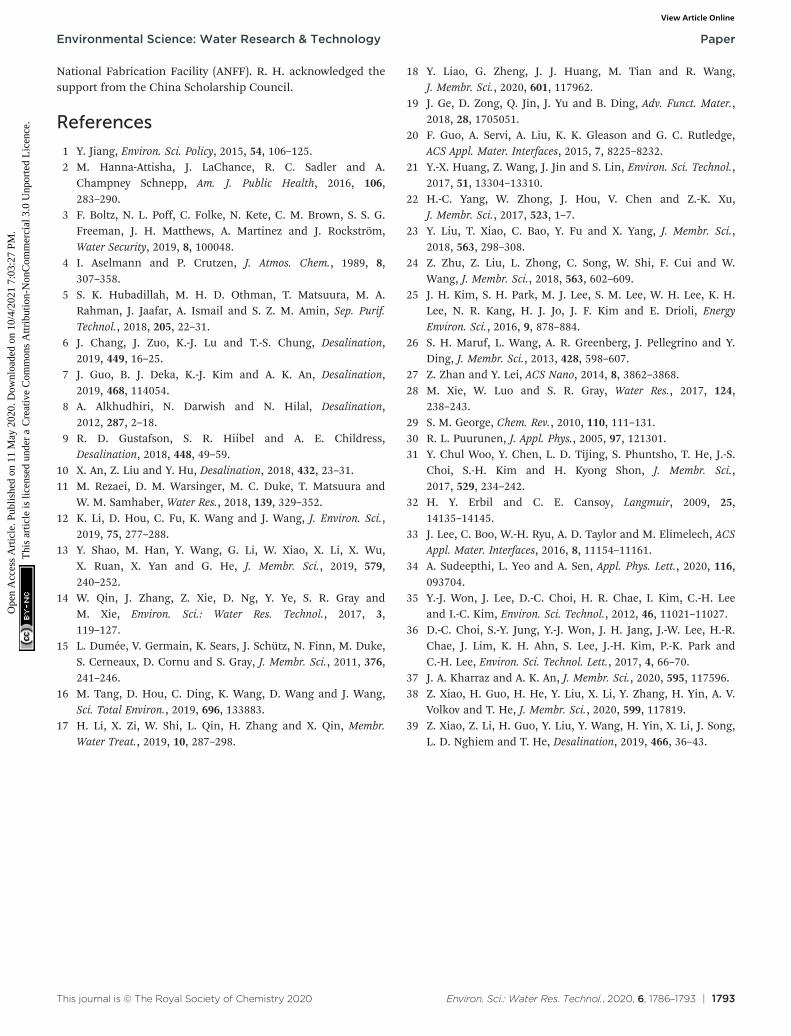
One important hindrance in the deployment of the MDmembrane for challenging waste streams is membranefouling and fouling reversibility after cleaning. The MDmembrane possessing a fluorinated hierarchically roughnanostructure membrane surface was tested in three fouling–cleaning cycles where a brief (20 minutes), physicalmembrane flushing (doubling crossflow velocity) using DIwater was carried out as membrane cleaning. A highlysatisfactory water flux recovery was observed in the secondand third cycles, achieving a water flux recovery of 91.3% and97.1%, respectively (Fig. 6B). Such high water flux recoveries
Fig. 4 Water and low surface tension liquid (diiodomethane, ethyleneglycol and ethanol) contact angles of C-PTFE and ALD and FTESmodified membranes. Error bars indicate the standard deviation ofthree repeated measurements from two membrane samples.
Environmental Science: Water Research & Technology Paper
could be attributed to the nanostructured surface pattern onthe MD membrane. A highly ordered periodic, circular
surface pattern can potentially minimize the foulant–membrane interaction during the filtration. This high foulingreversibility was consistent with our previous results andrecent literature.35–38 Apart from the topological perspective,the fluorinated TiO2 thin film layer on the membrane surfacealso renders high slip properties (low adhesion) againstfoulants during filtration. Indeed, the patterned surface withfluorination may alter the foulant deposition from a pinnedstate to suspended state.38 Similar observations were alsoreported in gypsum scaling in the MD process with asuperhydrophobic micropillared PVDF membrane.39 Bothfactors contributed to the excellent fouling reversibility,which is vital for the sustainable and robust MD membranefiltration for wastewater treatment.
4. Conclusion
Results reported here demonstrated a facile and scalablemethod to fabricate a nanopatterned, omniphobic PTFEmembrane via nanoimprinting, atomic layer deposition(ALD), and fluorination for membrane distillation. Thenanofabricated MD membrane was imparted with a highlyordered circle pattern and spherical hierarchical roughstructure, thereby achieving superhydrophobicity with a watercontact angle of 155° and anti-wetting potency for low surfacetension liquids. As a result, the nanofabricated MDmembrane manifested robust durability with a high andstable water flux of around 34 L m−2 h−1 for more than 24hours, and near 100% salt rejection in the presence of lowsurface tension surfactants. More importantly, ourmodification imparted fouling reversibility, achieving over91.3% water flux recovery after three fouling–cleaning cycles.
Conflicts of interest
There are no conflicts to declare.
Acknowledgements
This work was performed in part at the Melbourne Centre forNanofabrication (MCN) in the Victorian Node of the Australian
Fig. 5 Comparison of the filtration performance of C-PTFE and ALD and FTES modified membranes: (A) permeate conductivity and (B) water flux.
Fig. 6 Performance of the FTES modified membrane in membranedistillation after three fouling–cleaning cycles: (A) water flux declinecurve; (B) calculated water flux recovery rate after each cycle. Thewater flux recovery was calculated as the ratio between the initialwater fluxes of two consecutive filtration cycles.
Environmental Science: Water Research & TechnologyPaper
National Fabrication Facility (ANFF). R. H. acknowledged thesupport from the China Scholarship Council.
References
1 Y. Jiang, Environ. Sci. Policy, 2015, 54, 106–125.2 M. Hanna-Attisha, J. LaChance, R. C. Sadler and A.
Champney Schnepp, Am. J. Public Health, 2016, 106,283–290.
3 F. Boltz, N. L. Poff, C. Folke, N. Kete, C. M. Brown, S. S. G.Freeman, J. H. Matthews, A. Martinez and J. Rockström,Water Security, 2019, 8, 100048.
4 I. Aselmann and P. Crutzen, J. Atmos. Chem., 1989, 8,307–358.
5 S. K. Hubadillah, M. H. D. Othman, T. Matsuura, M. A.Rahman, J. Jaafar, A. Ismail and S. Z. M. Amin, Sep. Purif.Technol., 2018, 205, 22–31.
6 J. Chang, J. Zuo, K.-J. Lu and T.-S. Chung, Desalination,2019, 449, 16–25.
7 J. Guo, B. J. Deka, K.-J. Kim and A. K. An, Desalination,2019, 468, 114054.
8 A. Alkhudhiri, N. Darwish and N. Hilal, Desalination,2012, 287, 2–18.
9 R. D. Gustafson, S. R. Hiibel and A. E. Childress,Desalination, 2018, 448, 49–59.
10 X. An, Z. Liu and Y. Hu, Desalination, 2018, 432, 23–31.11 M. Rezaei, D. M. Warsinger, M. C. Duke, T. Matsuura and
W. M. Samhaber, Water Res., 2018, 139, 329–352.12 K. Li, D. Hou, C. Fu, K. Wang and J. Wang, J. Environ. Sci.,
2019, 75, 277–288.13 Y. Shao, M. Han, Y. Wang, G. Li, W. Xiao, X. Li, X. Wu,
X. Ruan, X. Yan and G. He, J. Membr. Sci., 2019, 579,240–252.
14 W. Qin, J. Zhang, Z. Xie, D. Ng, Y. Ye, S. R. Gray andM. Xie, Environ. Sci.: Water Res. Technol., 2017, 3,119–127.
15 L. Dumée, V. Germain, K. Sears, J. Schütz, N. Finn, M. Duke,S. Cerneaux, D. Cornu and S. Gray, J. Membr. Sci., 2011, 376,241–246.
16 M. Tang, D. Hou, C. Ding, K. Wang, D. Wang and J. Wang,Sci. Total Environ., 2019, 696, 133883.
17 H. Li, X. Zi, W. Shi, L. Qin, H. Zhang and X. Qin, Membr.Water Treat., 2019, 10, 287–298.
18 Y. Liao, G. Zheng, J. J. Huang, M. Tian and R. Wang,J. Membr. Sci., 2020, 601, 117962.
19 J. Ge, D. Zong, Q. Jin, J. Yu and B. Ding, Adv. Funct. Mater.,2018, 28, 1705051.
20 F. Guo, A. Servi, A. Liu, K. K. Gleason and G. C. Rutledge,ACS Appl. Mater. Interfaces, 2015, 7, 8225–8232.
21 Y.-X. Huang, Z. Wang, J. Jin and S. Lin, Environ. Sci. Technol.,2017, 51, 13304–13310.
22 H.-C. Yang, W. Zhong, J. Hou, V. Chen and Z.-K. Xu,J. Membr. Sci., 2017, 523, 1–7.
23 Y. Liu, T. Xiao, C. Bao, Y. Fu and X. Yang, J. Membr. Sci.,2018, 563, 298–308.
24 Z. Zhu, Z. Liu, L. Zhong, C. Song, W. Shi, F. Cui and W.Wang, J. Membr. Sci., 2018, 563, 602–609.
25 J. H. Kim, S. H. Park, M. J. Lee, S. M. Lee, W. H. Lee, K. H.Lee, N. R. Kang, H. J. Jo, J. F. Kim and E. Drioli, EnergyEnviron. Sci., 2016, 9, 878–884.
26 S. H. Maruf, L. Wang, A. R. Greenberg, J. Pellegrino and Y.Ding, J. Membr. Sci., 2013, 428, 598–607.
27 Z. Zhan and Y. Lei, ACS Nano, 2014, 8, 3862–3868.28 M. Xie, W. Luo and S. R. Gray, Water Res., 2017, 124,
238–243.29 S. M. George, Chem. Rev., 2010, 110, 111–131.30 R. L. Puurunen, J. Appl. Phys., 2005, 97, 121301.31 Y. Chul Woo, Y. Chen, L. D. Tijing, S. Phuntsho, T. He, J.-S.
Choi, S.-H. Kim and H. Kyong Shon, J. Membr. Sci.,2017, 529, 234–242.
32 H. Y. Erbil and C. E. Cansoy, Langmuir, 2009, 25,14135–14145.
33 J. Lee, C. Boo, W.-H. Ryu, A. D. Taylor and M. Elimelech, ACSAppl. Mater. Interfaces, 2016, 8, 11154–11161.
34 A. Sudeepthi, L. Yeo and A. Sen, Appl. Phys. Lett., 2020, 116,093704.
35 Y.-J. Won, J. Lee, D.-C. Choi, H. R. Chae, I. Kim, C.-H. Leeand I.-C. Kim, Environ. Sci. Technol., 2012, 46, 11021–11027.
36 D.-C. Choi, S.-Y. Jung, Y.-J. Won, J. H. Jang, J.-W. Lee, H.-R.Chae, J. Lim, K. H. Ahn, S. Lee, J.-H. Kim, P.-K. Park andC.-H. Lee, Environ. Sci. Technol. Lett., 2017, 4, 66–70.
37 J. A. Kharraz and A. K. An, J. Membr. Sci., 2020, 595, 117596.38 Z. Xiao, H. Guo, H. He, Y. Liu, X. Li, Y. Zhang, H. Yin, A. V.
Volkov and T. He, J. Membr. Sci., 2020, 599, 117819.39 Z. Xiao, Z. Li, H. Guo, Y. Liu, Y. Wang, H. Yin, X. Li, J. Song,
L. D. Nghiem and T. He, Desalination, 2019, 466, 36–43.
Environmental Science: Water Research & Technology Paper