General rights Copyright and moral rights for the publications made accessible in the public portal are retained by the authors and/or other copyright owners and it is a condition of accessing publications that users recognise and abide by the legal requirements associated with these rights. • Users may download and print one copy of any publication from the public portal for the purpose of private study or research. • You may not further distribute the material or use it for any profit-making activity or commercial gain • You may freely distribute the URL identifying the publication in the public portal If you believe that this document breaches copyright please contact us providing details, and we will remove access to the work immediately and investigate your claim. Downloaded from orbit.dtu.dk on: Aug 26, 2018 Environmental Transmission Electron Microscopy in an Aberration-Corrected Environment Hansen, Thomas Willum; Wagner, Jakob Birkedal Published in: Microscopy and Microanalysis Link to article, DOI: 10.1017/S1431927612000293 Publication date: 2012 Document Version Publisher's PDF, also known as Version of record Link back to DTU Orbit Citation (APA): Hansen, T. W., & Wagner, J. B. (2012). Environmental Transmission Electron Microscopy in an Aberration- Corrected Environment. Microscopy and Microanalysis, 18(4), 684-690. DOI: 10.1017/S1431927612000293
Transcript
General rights Copyright and moral rights for the publications made accessible in the public portal are retained by the authors and/or other copyright owners and it is a condition of accessing publications that users recognise and abide by the legal requirements associated with these rights.
• Users may download and print one copy of any publication from the public portal for the purpose of private study or research. • You may not further distribute the material or use it for any profit-making activity or commercial gain • You may freely distribute the URL identifying the publication in the public portal
If you believe that this document breaches copyright please contact us providing details, and we will remove access to the work immediately and investigate your claim.
Downloaded from orbit.dtu.dk on: Aug 26, 2018
Environmental Transmission Electron Microscopy in an Aberration-CorrectedEnvironment
Hansen, Thomas Willum; Wagner, Jakob Birkedal
Published in:Microscopy and Microanalysis
Link to article, DOI:10.1017/S1431927612000293
Publication date:2012
Document VersionPublisher's PDF, also known as Version of record
Link back to DTU Orbit
Citation (APA):Hansen, T. W., & Wagner, J. B. (2012). Environmental Transmission Electron Microscopy in an Aberration-Corrected Environment. Microscopy and Microanalysis, 18(4), 684-690. DOI: 10.1017/S1431927612000293
Microscopy and Microanalysishttp://journals.cambridge.org/MAM
Additional services for Microscopy and Microanalysis:
Email alerts: Click hereSubscriptions: Click hereCommercial reprints: Click hereTerms of use : Click here
Environmental Transmission Electron Microscopy in an AberrationCorrected Environment
Thomas W. Hansen and Jakob B. Wagner
Microscopy and Microanalysis / Volume 18 / Issue 04 / August 2012, pp 684 690DOI: 10.1017/S1431927612000293, Published online: 12 June 2012
Link to this article: http://journals.cambridge.org/abstract_S1431927612000293
How to cite this article:Thomas W. Hansen and Jakob B. Wagner (2012). Environmental Transmission Electron Microscopy in an AberrationCorrected Environment. Microscopy and Microanalysis,18, pp 684690 doi:10.1017/S1431927612000293
Request Permissions : Click here
Downloaded from http://journals.cambridge.org/MAM, IP address: 192.38.90.17 on 08 Aug 2012
Environmental Transmission Electron Microscopyin an Aberration-Corrected Environment
Thomas W. Hansen* and Jakob B. Wagner
Center for Electron Nanoscopy, Technical University of Denmark, DK-2800 Kgs. Lyngby, Denmark
Abstract: The increasing use of environmental transmission electron microscopy ~ETEM! in materials scienceprovides exciting new possibilities for investigating chemical reactions and understanding both the interactionof fast electrons with gas molecules and the effect of the presence of gas on high-resolution imaging. A gaseousatmosphere in the pole-piece gap of the objective lens of the microscope alters both the incoming electron waveprior to interaction with the sample and the outgoing wave below the sample. Whereas conventional TEMsamples are usually thin ~below 100 nm!, the gas in the environmental cell fills the entire gap between the polepieces and is thus not spatially localized. By using an FEI Titan environmental transmission electron microscopeequipped with a monochromator and an aberration corrector on the objective lens, we have investigated theeffects on imaging and spectroscopy caused by the presence of the gas.
Already in the early days of transmission electron micros-copy ~TEM!, the idea of imaging samples in the presence ofgases and at elevated temperatures was proposed by Ruska~1942! and by Hashimoto and co-workers ~Hashimoto &Naiki, 1968!. These first environmental transmission elec-tron microscopes used the concept of differential pumping,i.e., evacuating the microscope column in multiple stageswith a pressure drop at each step. This pumping scheme hasbeen extensively developed over the years ~Boyes & Gai,1997! and is still used on commercial environmental trans-mission electron microscopes today, e.g., the TitanTM envi-ronmental transmission electron microscope from FEICompany ~Hillsboro, OR, USA!. The design Ruska used wasbased on inserting apertures in the pole pieces to createindependently pumped compartments in the microscopecolumn. Hashimoto and Naiki ~1968! also used a differen-tial pumping system; however, their approach was slightlydifferent. In their design, the apertures were incorporated asa gas reaction chamber in the specimen holder itself. Whereasthe Ruska model has the advantage that it does not imposeany restrictions on sample holders, the Hashimoto ap-proach offers the advantage of mobility between micro-scopes. In both approaches, a sample can be heated whileexposed to gases and imaged simultaneously.
Today both approaches are still used. FEI uses a modi-fied objective lens with pressure limiting apertures insertedin the bores of the pole pieces. In contrast, several experi-mental groups ~Creemer et al., 2008; De Jonge et al., 2010!have approached the challenge by adding electron transpar-ent windows above and below the sample in order toconfine the gas in a small volume around the sample with apath length through the gas of typically a few tens of
microns. Whereas the latter design allows high pressures,above atmospheric pressure has been shown ~Creemer et al.,2008!; it limits resolution due the electrons having to travelthrough the windows. Furthermore, it limits the spectro-scopic capabilities of the setup as the generated X-rays haveto escape through the windows.
In the beginning of the 21st century, transmissionelectron microscopes with aberration correctors on eitherthe condenser system or the objective lens were introduced.Such an addition to the microscope column could allow foratomic scale imaging of the surfaces of catalytically activemetal nanoparticles in their active state. However, it is stillunclear how the presence of gas in the objective lens affectsthe imaging properties of the microscope. The imagingproperties of a transmission electron microscope are opti-mized for a thin sample located at the eucentric height ofthe objective lens. In the case of a differentially pumpedenvironmental transmission electron microscope, the solidsample is still located in this plane, but the gas spans theentire pole piece gap. Furthermore, the pressure in the areassurrounding the objective lens is increased.
For environmental transmission electron microscopy~ETEM! experiments the topic of beam effects and beamdamage often crops up. Extreme care has to be taken whenconducting experiments under intense electron irradiation.Effects of the beam are often more severe at higher pressuresmainly due to ionization of gas molecules. The influence ofthese effects for a given sample can be difficult to predict. Aset of reference experiments can help deconvolve the effectscaused by the beam from those of other stimuli ~Simonsenet al., 2010!. Furthermore, the electron beam can be used in aconstructive way. Experiments have been carried out in ETEMusing the beam for nanolithography in the presence of a pre-cursor gas ~Sychugov et al., 2010; van Dorp et al., 2011!.
Since the late 1980s and early 1990s, nanoparticles havebeen an increasing area of research. The specific differences
Received October 31, 2011; accepted February 21, 2012*Corresponding author. E-mail: [email protected]
Microsc. Microanal. 18, 684–690, 2012doi:10.1017/S1431927612000293 Microscopy AND
in properties, such as free surface energy compared to thebulk counterparts, give them unique characteristics, andthey play an increasing role in fields as diverse as catalysis~Wieckowski et al., 2003! and medical applications ~Salata,2004!. More recently, the nutrition field has also expressedan interest in the field due to the possible toxicity ofnanoparticles ~Chaudhry et al., 2008; Tiede et al., 2008!. Thespecific properties of nanoparticles also leave them vulnera-ble to growth processes, known as sintering, especially whenexposed to harsh environments such as those found incatalytic converters, for example, where high temperaturesand oxidizing environments are often encountered ~Rostrup-Nielsen, 1983!. Accurate control of the size of nanoparticlesis important in many fields. The size of the nanoparticlesgoverns various properties such as optical ~Hampe, 1958!and electrical ~Herman & Rhodin, 1966! and also plays acrucial role in the activity of catalysts.
Catalyzed chemical reactions occur on active sites ofcatalytic material, which often take the form of metal nano-particles supported on high surface area metal oxides, forexample. Over the years, several mechanisms of sinteringhave been proposed. The two mechanisms mostly agreedupon are Ostwald ripening ~Granqvist & Buhrman, 1976!and particle migration and coalescence ~Wynblatt & Gjo-stein, 1975; Wanke, 1977!. These models have been appliedto various catalytic systems ~Flynn & Wanke, 1974!, and ithas been proposed that the mechanism can be derived fromthe particle size distribution ~Granqvist & Buhrman, 1976!.However, this has been and is still heavily debated ~Wanke,1977!. Quite possibly, the first stages of particle coarseningwill follow a mechanism different from what occurs whenan equilibrium state has been obtained.
Controlling the growth processes of nanoparticles istherefore of the utmost importance, and the processes havebeen studied widely over the years using various tools,among these are X-ray absorption, X-ray diffraction, andelectron microscopy. Whereas the first two techniques havebeen used extensively to study sintering in situ ~Borgnaet al., 1992; Rasmussen et al., 2004!, ETEM investigationsare less common ~Simonsen et al., 2010!. However, it is theonly technique that will provide direct insight into theactual processes.
Most studies on sintering rely solely on postmortemstudies, and most of them are based on conventional TEMinvestigations. Such studies reveal only changes in the sizedistributions and not through which mechanism thesechanges occurred. With the advent of in situ TEM, theprocesses can be investigated as they occur.
One parameter that hampers in situ TEM studies is theeffect of the electron beam on the sample. This effect is notwell understood and only rarely described in the literature.Howe et al. ~2004! carried out an experimental study of themelting behavior of aluminum-silicon alloys, and Gryaznovet al. ~1991! calculated temperatures of supported metalnanoparticles exposed to an electron beam as a function ofcurrent density. More recently, Simonsen et al. ~2010! con-ducted in situ TEM investigations of model catalytic sys-
tems of platinum nanoparticles supported on thin films ofalumina. Here they perform a detailed analysis of the effectof the beam, without giving a physical description of theinteraction. Interaction of the high-energy electrons withgas and sample can have multiple results, ionization ofgases, local heating of the sample, knock-on damage result-ing in changes in the nanoparticle morphology, etc. How-ever, even though the fundamentals of these processes arenot well understood, important information can be ex-tracted from such in situ experimentation if the effects ofthe beam are known, at least on a qualitative level.
The aim of this investigation is to study the effects ofthe gas in the objective lens on the imaging properties of themicroscope.
MATERIALS AND METHODS
In the present study, an FEI Titan 80-300 environmentaltransmission electron microscope was used. The micro-scope uses a three stage differential pumping system allow-ing a pressure on the order of 102–103 Pa in the highpressure region giving a path length through the highpressure region on the order of 7 mm. Under these condi-tions, the ultrahigh vacuum conditions at the field emissionelectron source are maintained. Gas is introduced through aport in the objective lens with the flow controlled by digitalmass flow controllers. Details of this microscope can befound in Hansen et al. ~2010!. Furthermore, the microscopefeatures an aberration corrector on the objective lens bring-ing the resolution to below 1 Å.
To monitor the number of scattering events in the gasphase resulting in a loss of acquired electrons, the beamcurrent density on the charge-coupled device ~CCD! cam-era ~US1000, Gatan, Inc., Pleasanton, CA, USA! was moni-tored as a function of gas pressure. The current density wasmeasured using the fluorescent screen that was calibratedagainst a Faraday cup in the sample plane in a separateexperiment carried out in vacuum. Intensities were re-corded for various gas species at various pressures. To avoideffects of beam broadening as a result of electrons scatteringoutside the CCD region, the beam was deliberately keptfairly condensed on the central part of the CCD camera. Toestablish the intensity of the unperturbed beam, the signalwas first measured in vacuum ~,10�4 Pa! and then up to avalue close to the maximum allowed by the differentialpumping system. The pressure was measured using a sensorwith a displacing metal membrane for pressure measure-ment ~Barocel� 622!. After approximately 5 min at eachflow, the pressure reached a stable level and the electronbeam intensity could be measured.
To determine the effect of gas in the objective lens onspatial frequency, transmission images of a homogeneousamorphous carbon film were acquired as a function of gaspressure. As the change in gas flow induces a change inheight of the amorphous carbon membrane, the height ofthe sample was mechanically readjusted using the samplestage while keeping the current in the objective lens con-
Aberration-Corrected ETEM 685
stant. This procedure allowed us to rule out variations inthe imaging properties as a function of defocus of themicroscope itself. The defocus value was determined fromthe aberration corrector software. Rotational averages wereextracted from the Fourier transforms of these images, andthe profiles compared. To determine if the electron beamhad a damaging influence on the carbon film, an image wasacquired after evacuating the gas from the objective lens.
Model catalytic systems were prepared by depositinggraphene flakes suspended in ethanol on 3 mm gold TEMgrids coated with a lacey amorphous carbon film. Afterdrying under a heat lamp, 1 nm of gold was sputter coatedonto the grid. The gold coating readily formed nanoparti-cles with diameters ranging from ca. 1–5 nm.
The grid was placed in a resistive heating holder. Afterinsertion in the microscope, 2 NmL/min of hydrogen wasintroduced into the sample region of the microscope. A fewseconds after introduction, the pressure was stable at 130 Paand the temperature was gradually increased. After a fewminutes the temperature was stable at ca. 4008C. The tem-perature increase results in spatial drift of the holder due tothermal expansion of the holder assembly, the grid, and thesample. After ca. 15–20 min the drift reached a level whereinterpretable image sequences could be acquired. To main-tain good resolution, the image series were acquired withshort acquisition times ~0.5 s!, which were subsequentlydrift corrected using a cross-correlation algorithm.
RESULTS AND DISCUSSION
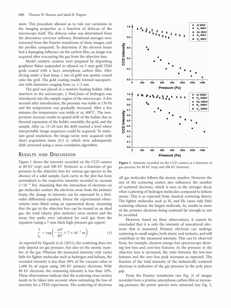
Figure 1 shows the intensity recorded on the CCD cameraat 80 kV ~top! and 300 kV ~bottom! as a function of gaspressure in the objective lens for various gas species in theabsence of a solid sample. Each curve in the plot has beennormalized to the respective intensity recorded in vacuum~,10�4 Pa!. Assuming that the interaction of electrons ongas molecules scatters the electrons away from the primarybeam, the change in intensity can be expressed by a first-order differential equation. Hence the experimental obser-vations were fitted using an exponential decay. Assumingthat the gas in the objective lens can be treated as an idealgas, the total ~elastic plus inelastic! cross section and themean free paths were calculated for each gas from theequation ~using a 7 mm thick high pressure gas region!
I
I0
� exp��sP
RT� 7 �10�3 m�. ~1!
As reported by Yaguchi et al. ~2011!, the scattering does notonly depend on gas pressure, but also on the atomic num-ber of the gas. Whereas the measured intensity only varieslittle for lighter molecules such as hydrogen and helium, therecorded intensity is less than 30% of the vacuum value in1,400 Pa of argon using 300 kV primary electrons. With80 kV electrons, the remaining intensity is less than 10%.These observations indicate that the scattering cross sectionneeds to be taken into account when estimating the loss ofintensity for a TEM experiment. The scattering of electrons
off gas molecules follows the atomic number. However, thesize of the scattering centers also influences the numberof scattered electrons, which is seen as the stronger decaywhen scattering of hydrogen molecules compared to heliumatoms. This is as expected from classical scattering theory.The lighter molecules such as H2 and He cause only littlescattering whereas the largest molecule, Ar, results in moreof the primary electrons being scattered far enough to notbe recorded.
However, based on these observations, it cannot beconcluded that it is only the intensity of unscattered elec-trons that is measured. Primary electrons can undergoscattering to small angles, both elastic and inelastic, and stillcontribute to the measured intensity. This can be observedfrom, for example, electron energy-loss spectroscopy show-ing low-loss and core-loss features. As the pressure in theobjective lens is increased, the ratio between the low-lossfeatures and the zero loss peak increases as expected. Thefraction of the total intensity of the inelastically scatteredelectrons is indicative of the gas pressure in the pole piecegap.
From the Fourier transforms ~see Fig. 2! of imagesrecorded from a pristine amorphous carbon film at increas-ing pressure, the power spectra were extracted ~see Fig. 2,
Figure 1. Intensity recorded on the CCD camera as a function ofgas pressure for 80 kV ~top! and 300 kV ~bottom!.
686 Thomas W. Hansen and Jakob B. Wagner
bottom!. As described in the Materials and Methods sec-tion, the height of the sample was adjusted prior to eachacquisition using the sample stage so the calculated defocusvalue was approximately 410 nm as measured using theThon ring measurement in the aberration-corrector soft-ware. In the radial intensity profiles of the power spectra,the maxima and minima of the power spectrum are wellaligned. Similar observations ~not shown here! at 80 kV showa rapid decrease of the contrast transfer already at 330 Paargon. In the presence of lighter gas molecules, this dampen-ing is significantly less pronounced. The dampening of thecontrast transfer results primarily from inelastic scatteringoff gas molecules as described by Reimer and Kohl ~2008!.Scattering off-gas molecules can thus be included in the con-trast transfer function as an increase in the angular distribu-tion of the electrons with the added complexity that thescattering occurs not only in the eucentric plane, but through-
out the objective lens pole piece gap. However, at relativelylow pressures the effect is not detrimental to the image forma-tion. One advantage of the differentially pumped system isthat the gas is evacuated from the sample region directly aboveand below the sample. This provides a centro-symmetric sym-metry of the pressure in the sample plane and directionalcutoffs are not observed on the fast Fourier transform ~FFT!.A rigorous analytical derivation of the effects of this scatter-ing is beyond the scope of the present work.
A more severe effect of the presence of gas around thesample is damage on the sample and support film primarilyin the form of etching. This effect can be minimized bykeeping the beam current density low. For this reason, thecurrent density was deliberately kept low for the presentobservations, on the order of 1 A/cm2. The effect on theamorphous film was monitored by recording an image invacuum after the experiment. The FFT of this image indi-
Figure 2. Fourier transforms of images acquired from an amorphous carbon film in vacuum ~top left! and at 1,700 Paargon gas ~top right!. From the FFTs, the radial intensity has been extracted ~bottom!. Values at intermediate pressuresand a simulation made using CTFExplorer are also included in the plot.
Aberration-Corrected ETEM 687
cates that the damage sustained by the film was insignificant~see Fig. 2, bottom plot!.
Each scattering event causes the electrons to travel at anangle to the optical axis. Assuming that these angles follow aGaussian distribution, summing over the entire distributionwill result in a dampening of the contrast transfer thatfollows an exponential decay. For a rigorous derivation seeReimer and Kohl ~2008!. The dampening of the powerspectra was fitted by first plotting the normalized peak-to-peak intensity as a function of k ~see Fig. 3!. In the pressurerange investigated, the dampening follows an exponentialdecay as expected.
The optimal conditions provided by the aberration-corrected environmental transmission electron microscopehave been used to investigate the growth processes of goldnanoparticles supported on graphene, a pseudo two-dimensional substrate. This system has been chosen to modelan industrial catalytic system while limiting some of the com-plexity offered by technically relevant catalysts.
Most experiments related to catalysis are performed inan atmosphere consisting of lighter molecules than argon.Often the reduction process of transition metal oxides in ahydrogen atmosphere is the topic of investigation. Suchexperiments can be carried out at reasonably low pressures,often below 500 Pa. As seen from Figure 1 and Table 1, suchan environment affects the imaging considerably less than ahigh pressure argon atmosphere.
Figure 4 shows images of gold particles supported ongraphene under vacuum and different hydrogen pressures.In all images the projected surfaces of the gold particles areclearly resolved and interpretable. Even at the highest pres-sure, no visible deterioration of the image resolution isobserved. The ~311! planes of gold with a lattice spacing of1.23 Å are resolved in all three images. Also the graphenesubstrate is almost invisible as expected from images ac-quired at low CS and close to zero defocus.
At room temperature, the gold particles are reasonablystable on the graphene flakes. In the presence of the electron
beam, they tend to mostly make irregular movements arounda fixed site rather than migrate laterally across the substrate,both in vacuum and in the presence of hydrogen. This phe-nomenon has also been observed when using boron nitrideas support material. As the primary energy of the electronsis significantly above the threshold for knock-on damage ofgraphene sheets ~Smith & Luzzi, 2001; Girit et al., 2009!,such motion may be related to restructuring of the graphenesubstrate rather than inherently related to the dynamics ofthe gold nanoparticles. The substrate restructuring is alsoobserved in lower magnification image sequences where thegraphene sheets as a whole change shape and deteriorate inthe presence of the electron beam. Such restructuring canmove the gold nanoparticles into direct contact with eachother, subsequently resulting in particle coalescence. Eventhough the influence of the high-energy electrons on thegraphene are significantly more pronounced at 300 kV com-pared to, for example, 80 kV, 300 kV was chosen due to thedetrimental effects on the imaging properties of loweringthe acceleration voltage, as shown in Figure 1.
Upon increasing the temperature, the gold nanoparti-cles become dynamic. When keeping the beam currentdensity reasonably low, observation of coalescence eventscan be observed without significant damage to the support-ing substrate. The graphene substrate in the electron beamseems to be more stable at elevated temperature as alsosuggested in the literature ~Tsetseris & Pantelides, 2009!. Inmost cases, the gold nanoparticles migrate as crystallineentities across the substrate. As they come into contact, abridge of material is formed linking the particles together~see Fig. 5!. Once the bridge has been formed and atoms canmigrate from particle to particle, an equilibrium state isquickly attained. The lattice fringes of both the constituentparticles and the resulting particle are resolved throughoutthe process. The image quality is clearly diminished atelevated temperature. This is due primarily to the drift inthe specimen holder, but also to the magnetic field resultingfrom the heating coil in the heating holder.
Figure 3. Normalized step height determined from FFTs of im-ages of amorphous carbon film in vacuum and in 1,700 Pa argon.The data have been fitted using an exponential decay.
Table 1. Scattering Cross Section and Mean Free Paths fromGases Typically Used in the Environmental Transmission ElectronMicroscope.
In Figure 6, stills extracted from an image sequencerecorded at 4008C in 200 Pa of hydrogen are shown. Thelower particle in the images is seen to gradually becomesmaller and the larger particle located just above it becomeslarger indicating a transfer of mass from the smaller to thelarger particle. This indicates that the particles under theseconditions can grow by Ostwald ripening. Under the sameconditions rapid coalescence was also observed. Hence asingle growth mechanism cannot be assumed, and presum-ably the overall coarsening of a nanoparticle ensemble fol-lows multiple routes. A recent study conducted on industrialcatalysts has shown that initial sintering follows an Ostwaldripening mechanism ~Challa et al., 2011!. As the presentinvestigations were done on a model substrate, the adhesionproperties of the particles can be different giving rise todifferent sintering mechanisms.
Even though the experiment is heavily prone to beameffects, fundamental growth mechanisms can be observed.More importantly, the aberration-corrected microscope givesaccess to directly interpretable images of nanoparticles.
CONCLUSIONS
Even though electron intensity is lost when there is a gasin the objective lens, full advantage can still be taken ofthe benefits of aberration correction. Light molecules suchas hydrogen and helium only have small effects on theincident electron wave even at relatively high pressures.With heavier molecules, care has to be taken as a largefraction of the intensity will be lost upon passage of theobjective lens.
In situ observations show that sintering of supportedmetal nanoparticles can occur via both particle migrationand coalescence and Ostwald ripening. Observations ofthese mechanisms occurring simultaneously were also made.
In situ observations made under a gaseous atmospherecan provide new insight into materials behavior. However,care has to be taken when conducting such experiments.The presence of the electron beam can seriously affect theobservations. However, with the appropriate precautions,new insight into the material can be obtained.
Figure 4. Gold nanoparticles supported on a graphene substrate. The images are ~from left to right! recorded invacuum ~10�4 Pa!, and in 290 Pa and 430 Pa of hydrogen, respectively.
Figure 5. Gold nanoparticles supported on graphene. Each image is extracted from a movie acquired over ca. 2 min in200 Pa hydrogen at 1008C. The images are acquired at 0, 55, 56, 58, and 94 s, respectively.
Figure 6. Stills from an image sequence recorded at 4008C in 200 Pa hydrogen. The lower particle gradually decreases insize while the neighboring larger particle grows in size. The images are acquired after 0, 13, 42, 46, and 48 s, respectively.
Aberration-Corrected ETEM 689
ACKNOWLEDGMENTS
The A.P. Møller and Chastine Mc-Kinney Møller Founda-tion is gratefully acknowledged for its contribution towardthe establishment of the Center for Electron Nanoscopy inthe Technical University of Denmark. Jörg Jinschek is grate-fully acknowledged for assistance, fruitful discussions, andcomments.
REFERENCESBorgna, A., Lenormand, F., Garetto, T., Apesteguia, C.R. &
Moraweck, B. ~1992!. Sintering of Pt/Al2O3 reformingcatalysts—EXAFS study of the behavior of metal particlesunder oxidizing atmosphere. Catal Lett 13, 175–188.
Boyes, E.D. & Gai, P.L. ~1997!. Environmental high resolutionelectron microscopy and applications to chemical science. Ultra-microscopy 67, 219–232.
Challa, S.R., Delariva, A.T., Hansen, T.W., Helveg, S., Se-hested, J., Hansen, P.L., Garzon, F. & Datye, A.K. ~2011!.Relating rates of catalyst sintering to the disappearance ofindividual nanoparticles during Ostwald ripening. J Am ChemSoc 133, 20672–20675.
Chaudhry, Q., Scotter, M., Blackburn, J., Ross, B., Boxall, A.,Castle, L., Aitken, R. & Watkins, R. ~2008!. Applications andimplications of nanotechnologies for the food sector. FoodAddit Contam 25, 241–258.
De Jonge, N., Bigelow, W.C. & Veith, G.M. ~2010!. Atmosphericpressure scanning transmission electron microscopy. Nano Lett10, 1028–1031.
Flynn, P.C. & Wanke, S.E. ~1974!. A model of supported metalcatalyst sintering—2. Application of model. J Catal 34, 400–410.
Girit, C.O., Meyer, J.C., Erni, R., Rossell, M.D., Kisielowski,C., Yang, L., Park, C.H., Crommie, M.F., Cohen, M.L., Louie,S.G. & Zettl, A. ~2009!. Graphene at the edge: Stability anddynamics. Science 323, 1705–1708.
Granqvist, C.G. & Buhrman, R.A. ~1976!. Size distributions forsupported metal catalysts—Coalescence growth versus Ostwaldripening. J Catal 42, 477–479.
Gryaznov, V.G., Kaprelov, A.M. & Belov, A.Y. ~1991!. Realtemperature of nanoparticles in electron microscope beams.Philos Mag Lett 63, 275–279.
Hampe, W. ~1958!. Beitrag zur Deutung der anomalen optichenEigenschaften feinstteiliger Metallkolloide in grosser Konzentra-tion. 1. Bestimmung des Fullfaktors dunner Schichten einesKolloids Gold-SiO2. Z Phys 152, 470–475.
Hansen, T.W., Wagner, J.B. & Dunin-Borkowski, R.E. ~2010!.Aberration corrected and monochromated environmental trans-mission electron microscopy: Challenges and prospects formaterials science. Mater Sci Technol 26, 1338–1344.
Hashimoto, H. & Naiki, T. ~1968!. High temperature gas reactionspecimen chamber for an electron microscope. Jpn J Appl Phys7, 946–952.
Howe, J.M., Yokota, T., Murayama, M. & Jesser, W.A. ~2004!.Effects of heat and electron irradiation on the melting behaviorof Al-Si alloy particles and motion of the Al nanosphere within.J Electron Microsc 53, 107–114.
Rasmussen, F.B., Sehested, J., Teunissen, H.T., Molenbroek,A.M. & Clausen, B.S. ~2004!. Sintering of Ni/Al2O3 catalystsstudied by anomalous small angle X-ray scattering. Appl CatalA 267, 165–173.
Reimer, L. & Kohl, H. ~2008!. Transmission Electron Microscopy:Physics of Image Formation. New York: Springer.
Ruska, E. ~1942!. Article on the super-microscopic image in highpressures. Kolloid-Z 100, 212–219.
Salata, O.V. ~2004!. Applications of nanoparticles in biology andmedicine. J Nanobiotechnol 2, 3.
Simonsen, S.B., Chorkendorff, I., Dahl, S., Skoglundh, M.,Sehested, J. & Helveg, S. ~2010!. Direct observations ofoxygen-induced platinum nanoparticle ripening studied by insitu TEM. J Am Chem Soc 132, 7968–7975.
Sychugov, I., Nakayama, Y. & Mitsuishi, K. ~2010!. Sub-10 nmcrystalline silicon nanostructures by electron beam induceddeposition lithography. Nanotechnology 21, 285307.
Tiede, K., Boxall, A.B.A., Tear, S.P., Lewis, J., David, H. &Hassellov, M. ~2008!. Detection and characterization of engi-neered nanoparticles in food and the environment. Food AdditContam 25, 795–821.
Tsetseris, L. & Pantelides, S.T. ~2009!. Adatom complexes andself-healing mechanisms on graphene and single-wall carbonnanotubes. Carbon 47, 901–908.
van Dorp, W.F., Lazic, I., Beyer, A., Golzhauser, A., Wagner,J.B., Hansen, T.W. & Hagen, C.W. ~2011!. Ultrahigh resolu-tion focused electron beam induced processing: The effect ofsubstrate thickness. Nanotechnology 22, 115303.
Wieckowski, A., Savinova, E. & Vayenas, C. ~2003!. Catalysisand Electrocatalysis at Nanoparticle Surfaces. New York: MarcelDekker.
Wynblatt, P. & Gjostein, N.A. ~1975!. Supported metal crystal-lites. Prog Solid State Chem 9, 21–58.
Yaguchi, T., Suzuki, M., Watabe, A., Nagakubo, Y., Ueda, K. &Kamino, T. ~2011!. Development of a high temperature-atmospheric pressure environmental cell for high-resolutionTEM. J Electron Microsc 60, 217–225.