106
al - English ioSpectrometer® 6135/6136/6137 EN) manual - English Register your instrument! www.eppendorf.com/myeppendorf Eppendorf BioSpectrometer ® 6135/6136/6137 Service manual - English
| Date post: | 16-Nov-2018 |
| Category: |
Documents |
| Upload: | truongcong |
| View: | 249 times |
| Download: | 3 times |

al - EnglishioSpectrometer® 6135/6136/6137EN)manual - English
Register your instrument! www.eppendorf.com/myeppendorf
Eppendorf BioSpectrometer® 6135/6136/6137Service manual - English

Copyright© 2014 by Eppendorf AG, Hamburg. All rights reserved, including graphics and images. No part
of this publication may be reproduced without the prior permission of the copyright owner.
Eppendorf® and the Eppendorf logo are registered trademarks of Eppendorf AG, Hamburg, Germany.
Eppendorf BioSpectrometer®, Eppendorf SpectraZoom® and UVette® are registered trademarks of
Eppendorf AG, Hamburg, Germany.
Cy is a registered trademark of GE Healthcare UK Ltd., Buckinghamshire, UK.
Hellma® is a registered trademark of Hellma GmbH & Co. KG, Müllheim, Germany.
Registered trademarks and protected trademarks are not marked in all cases with ® or ™ in this manual.
This product is manufactured under license to issued U.S. patent 6,122,052.
6135 920.019-02/022014

3Table of contents
Eppendorf BioSpectrometer® 6135/6136/6137
English (EN)
Table of contents
1 Operating instructions . . . . . . . . . . . . . . . . . . . . . . . . . . . . . . . . . . . . . . . . . . . . . . . . . . . . . . . . . . . . . . 51.1 Using this manual . . . . . . . . . . . . . . . . . . . . . . . . . . . . . . . . . . . . . . . . . . . . . . . . . . . . . . . . . . . . . 5
1.2 Danger symbols and danger levels . . . . . . . . . . . . . . . . . . . . . . . . . . . . . . . . . . . . . . . . . . . . . . . . 5
1.2.1 Danger symbols. . . . . . . . . . . . . . . . . . . . . . . . . . . . . . . . . . . . . . . . . . . . . . . . . . . . . . . . 5
1.2.2 Danger levels. . . . . . . . . . . . . . . . . . . . . . . . . . . . . . . . . . . . . . . . . . . . . . . . . . . . . . . . . . 5
2 Product description . . . . . . . . . . . . . . . . . . . . . . . . . . . . . . . . . . . . . . . . . . . . . . . . . . . . . . . . . . . . . . . . 72.1 Main illustration . . . . . . . . . . . . . . . . . . . . . . . . . . . . . . . . . . . . . . . . . . . . . . . . . . . . . . . . . . . . . . 7
3 Safety. . . . . . . . . . . . . . . . . . . . . . . . . . . . . . . . . . . . . . . . . . . . . . . . . . . . . . . . . . . . . . . . . . . . . . . . . . . . 93.1 User profile . . . . . . . . . . . . . . . . . . . . . . . . . . . . . . . . . . . . . . . . . . . . . . . . . . . . . . . . . . . . . . . . . . 9
3.2 Liability . . . . . . . . . . . . . . . . . . . . . . . . . . . . . . . . . . . . . . . . . . . . . . . . . . . . . . . . . . . . . . . . . . . . . 9
3.3 Hazard to persons . . . . . . . . . . . . . . . . . . . . . . . . . . . . . . . . . . . . . . . . . . . . . . . . . . . . . . . . . . . . . 9
3.4 Risk of equipment damage . . . . . . . . . . . . . . . . . . . . . . . . . . . . . . . . . . . . . . . . . . . . . . . . . . . . . 10
3.5 Hazards during repairs and shipping . . . . . . . . . . . . . . . . . . . . . . . . . . . . . . . . . . . . . . . . . . . . . 11
4 Operation. . . . . . . . . . . . . . . . . . . . . . . . . . . . . . . . . . . . . . . . . . . . . . . . . . . . . . . . . . . . . . . . . . . . . . . . 134.1 Overview of operating controls . . . . . . . . . . . . . . . . . . . . . . . . . . . . . . . . . . . . . . . . . . . . . . . . . . 13
4.1.1 Entering text . . . . . . . . . . . . . . . . . . . . . . . . . . . . . . . . . . . . . . . . . . . . . . . . . . . . . . . . . 14
5 Troubleshooting . . . . . . . . . . . . . . . . . . . . . . . . . . . . . . . . . . . . . . . . . . . . . . . . . . . . . . . . . . . . . . . . . . 175.1 General errors . . . . . . . . . . . . . . . . . . . . . . . . . . . . . . . . . . . . . . . . . . . . . . . . . . . . . . . . . . . . . . . 17
5.2 Error messages . . . . . . . . . . . . . . . . . . . . . . . . . . . . . . . . . . . . . . . . . . . . . . . . . . . . . . . . . . . . . . 18
5.3 Troubleshooting list for Service . . . . . . . . . . . . . . . . . . . . . . . . . . . . . . . . . . . . . . . . . . . . . . . . . 23
5.4 Result flags . . . . . . . . . . . . . . . . . . . . . . . . . . . . . . . . . . . . . . . . . . . . . . . . . . . . . . . . . . . . . . . . . 29
5.5 Service functions. . . . . . . . . . . . . . . . . . . . . . . . . . . . . . . . . . . . . . . . . . . . . . . . . . . . . . . . . . . . . 34
5.5.1 Navigation . . . . . . . . . . . . . . . . . . . . . . . . . . . . . . . . . . . . . . . . . . . . . . . . . . . . . . . . . . . 34
5.5.2 Activating service functions . . . . . . . . . . . . . . . . . . . . . . . . . . . . . . . . . . . . . . . . . . . . . 34
5.5.3 "Function check" subgroup. . . . . . . . . . . . . . . . . . . . . . . . . . . . . . . . . . . . . . . . . . . . . . 35
5.5.4 "Software" subgroup . . . . . . . . . . . . . . . . . . . . . . . . . . . . . . . . . . . . . . . . . . . . . . . . . . . 41
5.5.5 "Information" subgroup . . . . . . . . . . . . . . . . . . . . . . . . . . . . . . . . . . . . . . . . . . . . . . . . 43
5.5.6 "Adjustment" subgroup. . . . . . . . . . . . . . . . . . . . . . . . . . . . . . . . . . . . . . . . . . . . . . . . . 46
5.6 Customer service functions. . . . . . . . . . . . . . . . . . . . . . . . . . . . . . . . . . . . . . . . . . . . . . . . . . . . . 51
5.6.1 Navigation . . . . . . . . . . . . . . . . . . . . . . . . . . . . . . . . . . . . . . . . . . . . . . . . . . . . . . . . . . . 51
5.6.2 Activating customer service functions . . . . . . . . . . . . . . . . . . . . . . . . . . . . . . . . . . . . . 51
5.6.3 "Device settings" subgroup. . . . . . . . . . . . . . . . . . . . . . . . . . . . . . . . . . . . . . . . . . . . . . 52
5.6.4 "Device calibration" subgroup . . . . . . . . . . . . . . . . . . . . . . . . . . . . . . . . . . . . . . . . . . . 54
6 Disassembly/assembly . . . . . . . . . . . . . . . . . . . . . . . . . . . . . . . . . . . . . . . . . . . . . . . . . . . . . . . . . . . . . 616.1 Dismantling or replacing components . . . . . . . . . . . . . . . . . . . . . . . . . . . . . . . . . . . . . . . . . . . . 61
6.1.1 Required tools . . . . . . . . . . . . . . . . . . . . . . . . . . . . . . . . . . . . . . . . . . . . . . . . . . . . . . . . 61
6.1.2 Disassembling the housing . . . . . . . . . . . . . . . . . . . . . . . . . . . . . . . . . . . . . . . . . . . . . . 61
6.1.3 Replacing the lamp with the lamp holder . . . . . . . . . . . . . . . . . . . . . . . . . . . . . . . . . . . 62
6.1.4 Replacing the PCB BioSpectrometer . . . . . . . . . . . . . . . . . . . . . . . . . . . . . . . . . . . . . . 64
6.1.5 Replacing the switching power supply unit . . . . . . . . . . . . . . . . . . . . . . . . . . . . . . . . . 65
6.1.6 Replacing the display . . . . . . . . . . . . . . . . . . . . . . . . . . . . . . . . . . . . . . . . . . . . . . . . . . 66
6.1.7 Replacing the keypad . . . . . . . . . . . . . . . . . . . . . . . . . . . . . . . . . . . . . . . . . . . . . . . . . . 66
6.1.8 Dismantling the diffraction grating. . . . . . . . . . . . . . . . . . . . . . . . . . . . . . . . . . . . . . . . 67
Table of contentsEppendorf BioSpectrometer® 6135/6136/6137
English (EN)4
6.1.9 Dismantling the cuvette shaft . . . . . . . . . . . . . . . . . . . . . . . . . . . . . . . . . . . . . . . . . . . . 68
6.1.10 Replacing the fiber optic cable . . . . . . . . . . . . . . . . . . . . . . . . . . . . . . . . . . . . . . . . . . . 70
6.1.11 Replacing the PCB photo diode array . . . . . . . . . . . . . . . . . . . . . . . . . . . . . . . . . . . . . . 72
6.1.12 Replacing the photo diode array. . . . . . . . . . . . . . . . . . . . . . . . . . . . . . . . . . . . . . . . . . 73
6.1.13 Replacing the mirror . . . . . . . . . . . . . . . . . . . . . . . . . . . . . . . . . . . . . . . . . . . . . . . . . . . 74
6.1.14 Disassembling the fan . . . . . . . . . . . . . . . . . . . . . . . . . . . . . . . . . . . . . . . . . . . . . . . . . . 75
7 Alignment/adjustment . . . . . . . . . . . . . . . . . . . . . . . . . . . . . . . . . . . . . . . . . . . . . . . . . . . . . . . . . . . . . 777.1 Adjustment . . . . . . . . . . . . . . . . . . . . . . . . . . . . . . . . . . . . . . . . . . . . . . . . . . . . . . . . . . . . . . . . . 77
7.1.1 Required tools . . . . . . . . . . . . . . . . . . . . . . . . . . . . . . . . . . . . . . . . . . . . . . . . . . . . . . . . 77
7.1.2 Adjusting the diffraction grating. . . . . . . . . . . . . . . . . . . . . . . . . . . . . . . . . . . . . . . . . . 77
7.1.3 Adjusting the fiber-optic cable . . . . . . . . . . . . . . . . . . . . . . . . . . . . . . . . . . . . . . . . . . . 78
8 Software . . . . . . . . . . . . . . . . . . . . . . . . . . . . . . . . . . . . . . . . . . . . . . . . . . . . . . . . . . . . . . . . . . . . . . . . 798.1 Updating the device software . . . . . . . . . . . . . . . . . . . . . . . . . . . . . . . . . . . . . . . . . . . . . . . . . . . 79
9 Diagrams . . . . . . . . . . . . . . . . . . . . . . . . . . . . . . . . . . . . . . . . . . . . . . . . . . . . . . . . . . . . . . . . . . . . . . . . 819.1 Layout plans . . . . . . . . . . . . . . . . . . . . . . . . . . . . . . . . . . . . . . . . . . . . . . . . . . . . . . . . . . . . . . . . 81
9.1.1 BioSpectrometer basic . . . . . . . . . . . . . . . . . . . . . . . . . . . . . . . . . . . . . . . . . . . . . . . . . 81
9.1.2 BioSpectrometer kinetic . . . . . . . . . . . . . . . . . . . . . . . . . . . . . . . . . . . . . . . . . . . . . . . . 82
9.1.3 BioSpectrometer fluorescence . . . . . . . . . . . . . . . . . . . . . . . . . . . . . . . . . . . . . . . . . . . 83
10 Maintenance . . . . . . . . . . . . . . . . . . . . . . . . . . . . . . . . . . . . . . . . . . . . . . . . . . . . . . . . . . . . . . . . . . . . . 8510.1 Decontamination before shipment . . . . . . . . . . . . . . . . . . . . . . . . . . . . . . . . . . . . . . . . . . . . . . . 85
10.2 Shipping the device. . . . . . . . . . . . . . . . . . . . . . . . . . . . . . . . . . . . . . . . . . . . . . . . . . . . . . . . . . . 85
10.3 Service schedule . . . . . . . . . . . . . . . . . . . . . . . . . . . . . . . . . . . . . . . . . . . . . . . . . . . . . . . . . . . . . 85
10.4 Description of service . . . . . . . . . . . . . . . . . . . . . . . . . . . . . . . . . . . . . . . . . . . . . . . . . . . . . . . . . 87
11 Technical data . . . . . . . . . . . . . . . . . . . . . . . . . . . . . . . . . . . . . . . . . . . . . . . . . . . . . . . . . . . . . . . . . . . . 8911.1 Power supply. . . . . . . . . . . . . . . . . . . . . . . . . . . . . . . . . . . . . . . . . . . . . . . . . . . . . . . . . . . . . . . . 89
11.2 Ambient conditions . . . . . . . . . . . . . . . . . . . . . . . . . . . . . . . . . . . . . . . . . . . . . . . . . . . . . . . . . . . 89
11.3 Weight/dimensions . . . . . . . . . . . . . . . . . . . . . . . . . . . . . . . . . . . . . . . . . . . . . . . . . . . . . . . . . . . 90
11.4 Photometric properties . . . . . . . . . . . . . . . . . . . . . . . . . . . . . . . . . . . . . . . . . . . . . . . . . . . . . . . . 90
11.5 Incubation . . . . . . . . . . . . . . . . . . . . . . . . . . . . . . . . . . . . . . . . . . . . . . . . . . . . . . . . . . . . . . . . . . 91
11.6 Further technical parameters . . . . . . . . . . . . . . . . . . . . . . . . . . . . . . . . . . . . . . . . . . . . . . . . . . . 91
11.7 Application parameters . . . . . . . . . . . . . . . . . . . . . . . . . . . . . . . . . . . . . . . . . . . . . . . . . . . . . . . . 92
12 Ordering information . . . . . . . . . . . . . . . . . . . . . . . . . . . . . . . . . . . . . . . . . . . . . . . . . . . . . . . . . . . . . . 9312.1 Spare parts . . . . . . . . . . . . . . . . . . . . . . . . . . . . . . . . . . . . . . . . . . . . . . . . . . . . . . . . . . . . . . . . 101
12.1.1 Housing . . . . . . . . . . . . . . . . . . . . . . . . . . . . . . . . . . . . . . . . . . . . . . . . . . . . . . . . . . . . 101
12.1.2 Electrical/electronic equipment . . . . . . . . . . . . . . . . . . . . . . . . . . . . . . . . . . . . . . . . . 102
12.1.3 Light path . . . . . . . . . . . . . . . . . . . . . . . . . . . . . . . . . . . . . . . . . . . . . . . . . . . . . . . . . . 102
12.1.4 Accessories . . . . . . . . . . . . . . . . . . . . . . . . . . . . . . . . . . . . . . . . . . . . . . . . . . . . . . . . . 102
12.1.5 Auxiliary aids. . . . . . . . . . . . . . . . . . . . . . . . . . . . . . . . . . . . . . . . . . . . . . . . . . . . . . . . 103
13 Technical information . . . . . . . . . . . . . . . . . . . . . . . . . . . . . . . . . . . . . . . . . . . . . . . . . . . . . . . . . . . . 105

5Operating instructions
Eppendorf BioSpectrometer® 6135/6136/6137
English (EN)
1 Operating instructions1.1 Using this manual
Ensure that you have a copy of the latest versions of the service manual and operating instructions.
Check this using the version numbers at www.eppendorf-support.com and www.eppendorf.com.
Read the service manual before starting work on the device.
Read the chapters "Installation" and "Operation" of the operating manual.
Observe the safety instructions in the operating manual.
1.2 Danger symbols and danger levels
1.2.1 Danger symbols
1.2.2 Danger levels
The safety notes in this service manual contain the following degrees of danger:
Biohazard Explosion
Electric shock Cuts
Hazard point Material damage
DANGER Will lead to severe injuries or death.
WARNING May lead to severe injuries or death.
CAUTION May lead to light to moderate injuries.
NOTICE May lead to material damage.

Operating instructionsEppendorf BioSpectrometer® 6135/6136/6137
English (EN)6

7Product description
Eppendorf BioSpectrometer® 6135/6136/6137
English (EN)
2 Product description2.1 Main illustration
Abb. 2-1: Front and rear view
Fig. 2-1: Front and rear view
The name plate is located at the bottom left on the underside of the device.
1 Display
2 Cuvette shaft
3 Cuvette shaft cover
4 USB connection for USB stick
5 Power switch
6 Fuse holder
7 Power connection
8 USB connection for PC
9 Connection for RS-232 printer
10 Operating controls
standardsample
mno6jkl
5
13abc
2def4
ghi
pqrs7
tuv8
wxyz9
method
function
µ %0
exit
delete
enter blank
a b s o r b a n c e
absorbance
h e i g h t8 . 5 m m
10 9 8 7 6 5 4
1 2 33

Product descriptionEppendorf BioSpectrometer® 6135/6136/6137
English (EN)8
9Safety
Eppendorf BioSpectrometer® 6135/6136/6137
English (EN)
3 Safety3.1 User profile
The specialist entrusted with maintenance, repair or testing must meet the following prerequisites:
• Successful participation in service trainings with certification by Eppendorf AG for the product that is to
be maintained, repaired or tested.
• Qualification as a specialist with knowledge of the applicable local and international standards.
• Qualification to evaluate the work assigned to him.
• Recognition of potential hazards and how to prevent or correct them.
3.2 Liability
The Eppendorf service partner entrusted with maintenance, servicing or testing is liable for ensuring that
all work is carried out in a professional manner.
The constructional features of the device must not be modified by servicing, maintenance or testing.
The device must always be as safe as in its original state.
Only accessories and original spare parts recommended by Eppendorf as well as measuring and test
equipment recommended by Eppendorf may be used for any maintenance, servicing or testing work.
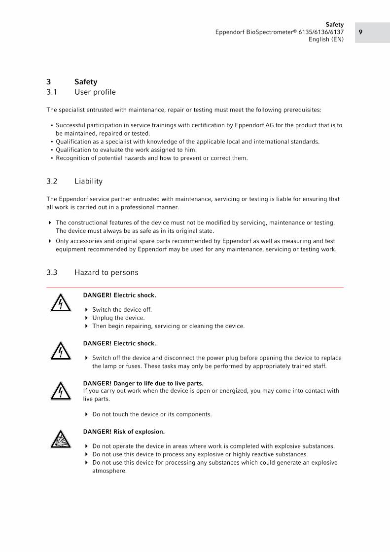
3.3 Hazard to persons
DANGER! Electric shock.
Switch the device off.
Unplug the device.
Then begin repairing, servicing or cleaning the device.
DANGER! Electric shock.
Switch off the device and disconnect the power plug before opening the device to replace
the lamp or fuses. These tasks may only be performed by appropriately trained staff.
DANGER! Danger to life due to live parts.If you carry out work when the device is open or energized, you may come into contact with
live parts.
Do not touch the device or its components.
DANGER! Risk of explosion.
Do not operate the device in areas where work is completed with explosive substances.
Do not use this device to process any explosive or highly reactive substances.
Do not use this device for processing any substances which could generate an explosive
atmosphere.

SafetyEppendorf BioSpectrometer® 6135/6136/6137
English (EN)10
3.4 Risk of equipment damage
WARNING! Lethal voltage in the area of the xenon lamp.The connections of the xenon lamp, its supply lines and connections on the PCB carry a live
voltage of 1000 V.
Never touch components that are under high voltage.
Only use tools that are specially protected against high voltages to adjust the xenon lamp.
WARNING! Burns due to ultraviolet radiation.The xenon lamp emits intensive ultraviolet radiation. This intensive ultraviolet radiation may
cause burns to the skin and eyes.
Wear protective glasses against ultraviolet radiation.
Protect your skin from the ultraviolet radiation.
Do not look into the light beam of the lamp.
WARNING! Risk from incorrect supply voltage
Only connect the device to voltage sources which correspond to the electrical
requirements on the name plate.
Only use sockets with a protective earth (PE) conductor and suitable power cable.
NOTICE! Damage to electrical components due to electrostatic discharge.Handling electrical components creates electrical fields. The electrical components are
destroyed when these fields are discharged. Minimize the build-up of electrostatic fields.
Store and transport sensitive components and assemblies in antistatic or conductive
packing.
Wear grounding strips, antistatic clothing and antistatic safety boots.
Use dissipative surfaces.
Grip the component on the edges.
Do not touch any protruding connections or conductors.
Prevent components from becoming electrostatically charged on plastics.
NOTICE! Damage due to overheating.
Do not place the device near heat sources (e.g., heater, drier compartment).
Do not expose the device to direct sunlight.
Guarantee unobstructed air circulation by maintaining a distance of at least 5 cm, on all
sides of the device, to the adjacent devices and the wall, and by keeping the device base
clear.
To keep the ventilation slits for the lamp at the rear of the device clear, do not place any
objects on the device.

11Safety
Eppendorf BioSpectrometer® 6135/6136/6137
English (EN)
3.5 Hazards during repairs and shipping
NOTICE! Damage to the xenon lamp from contamination.Grease and dirt on the glass part can lead to premature failure of the xenon lamp.
Only touch the xenon lamp with gloves.
Clean dirty xenon lamps before installing them.
To do this, moisten a soft cloth with pure alcohol.Use it to clean the glass part of the Xenon
lamp.
NOTICE! Corrosion from aggressive cleaning agents and disinfectants.
Do not use corrosive cleaning agents, aggressive solvents or abrasive polishes.
Do not incubate the accessories in aggressive cleaning agents or disinfectants for a longer
period of time.
NOTICE! Damage to electronic components due to condensation. Condensate can form in the device after it has been moved from a cool environment to a
warmer environment.
After installing the device, wait at least for 2 h. Only then connect the device to the mains.
WARNING! Infection by contaminated material.There may be contaminated material on the device and accessories.
Work may only be completed on a decontaminated device.
Find out more about contamination risks before beginning work.
Check the device decontamination certificate.
Wear personal protective equipment (protective gloves, protective goggles).
NOTICE! Damage as a result of incorrect packing.Eppendorf AG is not liable for damage caused by improper packing.
The device may only be stored and transported in its original packaging.

SafetyEppendorf BioSpectrometer® 6135/6136/6137
English (EN)12

13Operation
Eppendorf BioSpectrometer® 6135/6136/6137
English (EN)
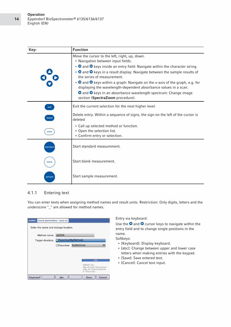
4 Operation4.1 Overview of operating controls
Abb. 4-1: Control panel of the BioSpectrometer
Fig. 4-1: Control panel of the BioSpectrometer
Key: Function
Keypad: Enter digits and text.
Keys 1 to 9 as well as 0: When entering text, next to numbers you also can
enter letters and special characters by pressing the key several times.
Alternatively, you can switch to a displayed keyboard with the [Keyboard] key.
Outside of entry fields: Call up method selection.
Outside of entry fields: Call up function selection.
Softkey: Select functions.
The key assignment changes along with the software dialog. The current
function is displayed directly above the key on the display.
OperationEppendorf BioSpectrometer® 6135/6136/6137
English (EN)14
4.1.1 Entering text
You can enter texts when assigning method names and result units. Restriction: Only digits, letters and the
underscore "_" are allowed for method names.
Move the cursor to the left, right, up, down.
• Navigation between input fields.
• and keys inside an entry field: Navigate within the character string.
• and keys in a result display: Navigate between the sample results of
the series of measurement.
• and keys within a graph: Navigate on the x-axis of the graph, e.g. for
displaying the wavelength-dependent absorbance values in a scan.
and keys in an absorbance wavelength spectrum: Change image
section (SpectraZoom procedure).
Exit the current selection for the next higher level.
Delete entry. Within a sequence of signs, the sign on the left of the cursor is
deleted
• Call up selected method or function.
• Open the selection list.
• Confirm entry or selection.
Start standard measurement.
Start blank measurement.
Start sample measurement.
Entry via keyboard:
Use the and cursor keys to navigate within the
entry field and to change single positions in the
name.
Softkeys:
• [Keyboard]: Display keyboard.
• [abc]: Change between upper and lower case
letters when making entries with the keypad.
• [Save]: Save entered text.
• [Cancel]: Cancel text input.
Key: Function

15Operation
Eppendorf BioSpectrometer® 6135/6136/6137
English (EN)
Entry via the displayed keyboard:
Use the cursor keys to select the displayed signs and
respectively confirm your selection with the enter
key. As for a PC key pad, you can use the "Shift"
resp. the "Caps Lock" key for changing the
capitalization for the next entry or for all following
entries.
Softkeys:
• [Numbers]: Switch to entry using the keyboard.
• [Save]: Save entered text.
• [Cancel]: Cancel text input.

OperationEppendorf BioSpectrometer® 6135/6136/6137
English (EN)16

17Troubleshooting
Eppendorf BioSpectrometer® 6135/6136/6137
English (EN)
5 Troubleshooting5.1 General errors
Error Possible cause Remedy
Measuring results are
imprecise.
• Reagent is past its shelf
life.
Ensure that the reagent is still within its
shelf life and properly prepared.
• Reagent has not been
prepared properly.
Use clean demineralized water of adequate
quality for preparation if required.
• Pipetting is not correct. Ensure that the pipette is calibrated and
that pipetting is being performed correctly.
• Incubation procedure
before measurement is
incorrect.
If the method procedure requires
incubation before the measurement,
ensure that the temperature and time for
incubation are correctly observed.
• The cuvette is
contaminated.
Clean and rinse the cuvette. When
replacing a cuvette, pay attention that the
optical window of the cuvette remains
clean and that you do not touch it with your
fingers.
If the cuvette window has become soiled
from fingerprints, wipe it clean using a
lint-free lab cloth soaked in ethanol or
isopropanol.
• The cuvette is not filled
completely with
measuring solution, and it
contains bubbles.
Ensure that the required minimum volume
of the cuvette for a measurement is
reached and that no bubbles are in the
measuring solution.
• Turbidity of the
measuring solution.
Centrifuge the turbid measuring solutions
containing particles and use the clear
supernatant.
• Spectrophotometer is
drifting.
Contact Eppendorf Service.
Observe the ambient conditions.
Prevent temperature changes.
• Cuvette shaft is dirty. Clean the cuvette shaft.
• Fluorimetry: Interfering
substances reinforce or
weaken the fluorescence
signal.
Remove the interfering substances.
If the interfering substances cannot be
removed, fluorimetry measurement
technology cannot be used.
• Fluorimetry: The cuvette
shaft cover is not closed.
Close the cuvette shaft cover prior to
measurement.

TroubleshootingEppendorf BioSpectrometer® 6135/6136/6137
English (EN)18
5.2 Error messages
You can exit device displays with error messages using the [OK] softkey.
System errors require an evaluation by the Technical Service. These errors are shown in English (System error …). Please contact Technical Service in these cases. Other error messages, for which you can carry
out troubleshooting measures, are illustrated in the table below.
The measuring results are
not correct.
• The method has not been
programmed correctly.
Ensure that the method parameters are
entered correctly.
• The standard solution has
not been prepared
correctly.
Ensure that the correct standard is used
and that the measuring solution for the
standard is prepared correctly.
• The absorbance of the
reagent is drifting.
For instable reagent absorbance and end
point methods: When measuring a long
series of samples, measure the reagent
blank value not only at the beginning but
also during the sample series. If the
reagent blank value drifts strongly, the
reagent is not appropriate for error-free
measurements and has to be replaced by a
new reagent.
• The cuvette is not
positioned correctly.
Position the cuvette in the cuvette shaft so
that the optical window points towards the
direction of the light path.
Photometry light path: from back to front
Fluorimetry light path: from right to left
Symptom/message
Cause Remedy BioSp BioSp_fluor
BioSp_kin
Self test failed. • Cuvette shaft cover was
open during self test.
• The cuvette shaft was not
empty during the self test.
Repeat the self test with
empty cuvette shaft and the
cuvette shaft cover closed.
• Device is faulty. Contact Eppendorf Service.
File export
failed.
During data export:
• USB stick improperly
formatted or faulty.
• USB stick removed from the
device too early (during the
export).
Reformat or replace the USB
stick.
Reconnect the USB stick and
repeat the export.
Error Possible cause Remedy

19Troubleshooting
Eppendorf BioSpectrometer® 6135/6136/6137
English (EN)
Failed to
initialize
printer.
• Printer not connected or
switched off.
• Printer not configured
correctly.
Connect the printer and
switch it on.
Reconfigure the printer.
For a correct configuration of
the printer settings refer to the
installation description.
Blank
measurement:
An intensity on
a pixel that
influences the
main, auxiliary
or scan
wavelength is
too low.
• The absorbance of the
blank solution used for the
blank measurement is too
high.
• Incorrect or turbid blank
solution.
• For scans: Wavelength
range is too large, because
the sample is very strongly
absorbed in part of the
wavelength range.
Check the blank solution and
remeasure the blank if
required.
For scans: Match the
wavelength range to the
sample spectrum.
Blank
measurement:
The emission
at the
measurement
wavelength is
too high.
• The fluorescence of the
blank solution used for the
blank measurement is too
high.
• Incorrect or turbid blank
solution.
Check the blank solution and
remeasure the blank.
X
The entered
name is not
valid.
• Error when entering the
name. Different causes are
possible. For the precise
cause please see the
information in the help box.
See information in the help
box.
A method (or
folder, dye,
protein,
nucleic acid, or
unit) with this
name already
exists.
• The name under which the
method was saved has
already been used for a
different method in the
same folder.
• The message also appears
after editing names already
given to a folder or to a
nucleic acid (dye, protein,
concentration unit) (under
General Method Parameter).
Assign a different name.
Symptom/message
Cause Remedy BioSp BioSp_fluor
BioSp_kin

TroubleshootingEppendorf BioSpectrometer® 6135/6136/6137
English (EN)20
The following
parameter
values are not
defined in
General Method Parameter:
• When opening a method
with parameters which
access General Method Parameter, the system
determined that at least one
parameter (dye, nucleic
acid, protein, unit) does not
exist there anymore, so
probably has been deleted.
Select a different parameter
from the existing list. If
necessary, program a new
list entry in General Method Parameter in order to be
able to use it when
programming a method.
The value of
the parameter
marked with * is not defined
in the Gen.
Param. Please
correct the
parameter.
This error message appears
when editing method
parameters.
• Parameter in General Method Parameter is not
defined.
Select a different parameter
from the existing list. If
necessary, program a new
list entry in General Method Parameter in order to be
able to use it when
programming a method.
Invalid zoom
interval.
During the Zoom process with
free entry of limits ([Free])
softkey):
• The zoom area is below the
lower limit.
Enter the values so that the
interval does not fall below
the range limits of 0.02 A
and 10 nm.
X
The entered
standard
concentrations
are not
monotonically
increasing
resp.
monotonically
falling. Please
correct the
standard
concentrations.
• See the error text. Enter the standard
concentrations so that the
first standard receives the
lowest concentration and the
other standard
concentrations form an
increasing sequence.
At least two of
the entered
standard
concentrations
are identical.
Please correct
the standard
concentrations.
• See the error text. Enter the standard
concentrations so that the
first standard receives the
lowest concentration and the
other standard
concentrations form an
increasing sequence.
Symptom/message
Cause Remedy BioSp BioSp_fluor
BioSp_kin

21Troubleshooting
Eppendorf BioSpectrometer® 6135/6136/6137
English (EN)
The measured
values are not
strictly
monotone!
• Error when measuring a
standard series: The
measured absorbance
values of the standard
series are not continuously
increasing or decreasing.
Repeat the standard
measurements or delete the
single, incorrectly measured
standard result.
The ID cannot
be set.
• Error when entering the
sample ID. Different causes
are possible. For the precise
cause please see the
information in the help box.
See information in the help
box.
The dilution
cannot be set.
• Error when entering the
dilution. Different causes
are possible. For the precise
cause please see the
information in the help box.
See information in the help
box.
Calculation not
possible
because of
division by
zero.
Absorbance
result or
Formula "b"
parameter is
zero.
• An absorbance result was
divided by a "zero" value
during the evaluation of a
Division type method (Dual wavelength method
group). This is not
mathematically permissible.
Check the reagents and
samples used and repeat the
measurement.
Do not enter "zero" as a
value for the Formula b
parameter.
X
There is only
one
measurement
left to be
performed in
this series of
measurement.
The maximum
number of
measurements
within one
series of
measurements
has been
reached.
• The number of
measurements in one
measuring series is limited
to 99.
Start a new series of
measurement after
maximally 99
measurements.
Symptom/message
Cause Remedy BioSp BioSp_fluor
BioSp_kin
TroubleshootingEppendorf BioSpectrometer® 6135/6136/6137
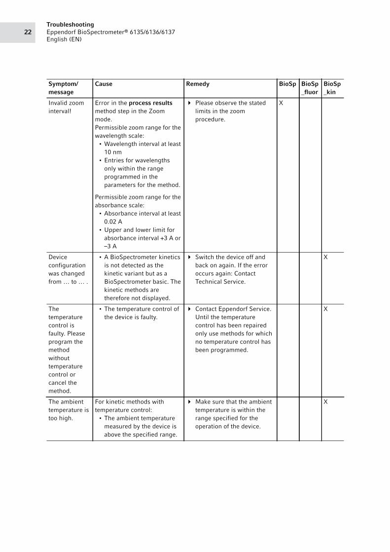
English (EN)22
Invalid zoom
interval!
Error in the process results
method step in the Zoom
mode.
Permissible zoom range for the
wavelength scale:
• Wavelength interval at least
10 nm
• Entries for wavelengths
only within the range
programmed in the
parameters for the method.
Permissible zoom range for the
absorbance scale:
• Absorbance interval at least
0.02 A
• Upper and lower limit for
absorbance interval +3 A or
–3 A
Please observe the stated
limits in the zoom
procedure.
X
Device
configuration
was changed
from … to … .
• A BioSpectrometer kinetics
is not detected as the
kinetic variant but as a
BioSpectrometer basic. The
kinetic methods are
therefore not displayed.
Switch the device off and
back on again. If the error
occurs again: Contact
Technical Service.
X
The
temperature
control is
faulty. Please
program the
method
without
temperature
control or
cancel the
method.
• The temperature control of
the device is faulty.
Contact Eppendorf Service.
Until the temperature
control has been repaired
only use methods for which
no temperature control has
been programmed.
X
The ambient
temperature is
too high.
For kinetic methods with
temperature control:
• The ambient temperature
measured by the device is
above the specified range.
Make sure that the ambient
temperature is within the
range specified for the
operation of the device.
X
Symptom/message
Cause Remedy BioSp BioSp_fluor
BioSp_kin

23Troubleshooting
Eppendorf BioSpectrometer® 6135/6136/6137
English (EN)
5.3 Troubleshooting list for Service
Linear
regression
could not be
applied to all
measurements.
• For kinetic methods, the
time frame for evaluation
with linear regression was
changed in the process results method step, and
the change should be
extended to all measuring
results. The required
number of measuring
points, however, was not
available for at least one
sample result.
Only change the time frame
for evaluation with linear
regression in the process results method step for
samples with sufficient
measuring points.
X
Symptom/message
Cause Remedy BioSp BioSp_fluor
BioSp_kin
Method
parameters
could not be
loaded!
• File system defective Restore factory settings.
Initialising
BioSpectromet
er 6135
FAILED
• Major software error
• Major hardware error
1. Carry out software update.
2. Replace the main board.
No response
from
spectrometer
unit.
• Spectrometer unit firmware
faulty.
• Spectrometer unit or cable
connection defective.
1. Restart.
2. Check cable connections.
3. Replace Spectrometer unit.
Could not
mount USB
storage.
• USB stick missing
• USB stick is defective.
• USB stick is missing or has
incorrect file system.
Connect operative USB stick
to FAT32 file system.
Could not
unmount USB
storage!
• USB stick removed during
access (e.g., export,
backup, …).
Reconnect USB stick and
carry out the process again.
Could not find
method: XXX.
Please delete
this method
and create a
new one!
• File system defective Restore factory settings.
Symptom/message
Cause Remedy BioSp BioSp_fluor
BioSp_kin

TroubleshootingEppendorf BioSpectrometer® 6135/6136/6137
English (EN)24
Pixel
wavelength
assignment
missing.
Please call
Eppendorf
service!
• Missing optical adjustment. Carry out optical
adjustment.
Error during
loading of
method. The
file may be
corrupted.
Please call EP
Service if you
cannot recover
the file!
• Method file faulty.
• File system defective.
1. Delete method.
2. Restore factory settings.
Method could
not be loaded.
• Method file faulty.
• File system defective.
1. Delete method.
2. Restore factory settings.
Various SPU
errors
• Spectrometer unit firmware
faulty.
• Spectrometer unit or cable
connection defective.
1. Restart.
2. Check cable connections.
3. Replace Spectrometer unit.
Error while
initializing
processing of
results.
• Method file faulty.
• File system defective.
1. Delete method.
2. Restore factory settings.
Result could
not be loaded.
Please try
again after
restart.
• Result faulty.
• File system defective.
Delete result.
Restore factory settings.
Spectrometer
Unit did not
produce a
result.
• Cable connection between
the basic printed circuit
board and photo diode
array printed circuit board
is defective.
• Photo diode array PCB
defective.
• Basic printed circuit board
defective.
Check the cable connection
between the basic printed
circuit board and photo
diode array printed circuit
board is defective.
Replace the photo diode
array printed circuit board.
Replace the basic printed
circuit board.
Symptom/message
Cause Remedy BioSp BioSp_fluor
BioSp_kin

25Troubleshooting
Eppendorf BioSpectrometer® 6135/6136/6137
English (EN)
An invalid
method
definition
prevents the
completion of
the result
computation.
The method
resource file
might be
corrupt.
• Method file faulty.
• File system defective.
1. Delete method.
2. Restore factory settings.
Invalid
filename.
• File system defective. Software update
Restore factory settings.
Could not eject
USB storage.
• USB stick removed during
access (e.g., export,
backup, …).
Reconnect USB stick and
carry out the process again.
Could not
prepare PC
storage.
• File system defective. Restore factory settings.
Replace the main board.
Error opening
file XXX
• File system defective. Restore factory settings.
Resource data
corrupted.
Backup was
being restored.
• File system defective. Restore factory settings.
Backup could
not be
restored.
Please call
Eppendorf
Service.
• File system defective. Restore factory settings.
Method could
not be saved.
• File system defective
• Not enough memory.
Delete old measuring results
and methods.
Restore factory settings.
Serial number
does not match
hardware type.
• Basic printed circuit board
is configured for D30.
Replace the basic printed
circuit board.
Key pad seems
to be
damaged,
please replace.
• Key pad defective. Replace key pad.
Unable to save
settings.
• File system defective.
• Not enough memory.
Delete old measuring results
and methods.
Restore factory settings.
Symptom/message
Cause Remedy BioSp BioSp_fluor
BioSp_kin

TroubleshootingEppendorf BioSpectrometer® 6135/6136/6137
English (EN)26
Could not read
filter settings
from USB
storage.
• USB stick with filter data is
missing.
• USB stick with filter data is
defective.
• USB stick does not contain
any valid filter data file.
Connect USB stick with valid
filter data.
Out of memory • File system defective.
• Not enough memory.
Delete old measuring results
and methods.
Restore factory settings.
Could not set
serial number
• Serial number invalid.
• EEPROM not writable.
Check serial number.
Replace the basic printed
circuit board.
Could not set
flash count
• File system defective.
• Not enough memory.
Carry out software update.
Replace the main board.
Could not read
temperature
from
temperature
unit.
• Tempering deactivated
because of error (e.g.,
overheating, defect).
1. Restart.
2. Check the cable connections
to the kinetic module.
3. Replace the kinetic module.
X
Temperature
control error
• Tempering deactivated
because of error (e.g.,
overheating, defect).
1. Restart.
2. Check the cable connections
to the kinetic module.
3. Replace the kinetic module.
X
Cuvette
temperature is
too high (max.
X °C).
• Cuvette shaft temperature
is too high.
Allow the cuvette shaft to
cool off.
X
Temperature
difference to
reference
sensor too
high
• Sensor faulty
• Basic printed circuit board
defective
Replace sensor.
Replace the basic printed
circuit board.
X
Difference
between
ambient
temperature
and
destination
temperature is
too high.
• Difference between the
inside temperature of the
housing and the set
temperature is too high.
• Sensor faulty
• Basic printed circuit board
defective
The device may only be
operated in preset
temperature ranges.
Replace sensor.
Replace the basic printed
circuit board.
X
Symptom/message
Cause Remedy BioSp BioSp_fluor
BioSp_kin

27Troubleshooting
Eppendorf BioSpectrometer® 6135/6136/6137
English (EN)
Temperature
cannot be
reached.
Temperature
unit will be
disabled.
• Cable connection defective.
• Peltier element defective.
Check cable connection.
Replace Peltier element.
X
Temperature
correction
could not be
saved.
• File system defective
• Not enough memory.
Software update
Replace the main board.
X
No
temperature
correction
function found.
• Temperature correction file
defective.
• File system defective
Carry out temperature
adjustment.
X
Fan failure • Fan is blocked.
• Fan is defective.
• Cable connection defective.
Check fan and cable
connection.
Replace fan and cable
connection.
X
The tempering
timeout is
greater than
1 h.
• Incorrect settings in the
configuration files (.xml).
Carry out software update. X
Fluorescence
unit did not
produce a
result.
• Old software version
• Cable connection between
basic printed circuit board
and fluorescence module
defective.
• Fluorescence module
defective.
• Basic printed circuit board
defective
Software update
Check the cable connection
between basic printed
circuit board and
fluorescence module.
Replace the fluorescence
module.
Replace the basic printed
circuit board.
X
Could not set
sensitivity for
fluorescence
measurement.
• Old software version
• Cable connection between
basic printed circuit board
and fluorescence module
defective.
• Fluorescence module
defective.
• Basic printed circuit board
defective
Software update
Check the cable connection
between basic printed
circuit board and
fluorescence module.
Replace the fluorescence
module.
Replace the basic printed
circuit board.
X
Symptom/message
Cause Remedy BioSp BioSp_fluor
BioSp_kin

TroubleshootingEppendorf BioSpectrometer® 6135/6136/6137
English (EN)28
Error setting
fluorescence
wavelength.
• Old software version
• Cable connection between
basic printed circuit board
and fluorescence module
defective.
• Fluorescence module
defective.
• Basic printed circuit board
defective
Software update
Check the cable connection
between basic printed
circuit board and
fluorescence module.
Replace the fluorescence
module.
Replace the basic printed
circuit board.
X
Error reading
result from
fluorescence
unit.
• Old software version
• Cable connection between
basic printed circuit board
and fluorescence module
defective.
• Fluorescence module
defective.
• Basic printed circuit board
defective
Software update
Check the cable connection
between basic printed
circuit board and
fluorescence module.
Replace the fluorescence
module.
Replace the basic printed
circuit board.
X
Response
timeout.
• Old software version
• Cable connection between
basic printed circuit board
and fluorescence module
defective.
• Fluorescence module
defective.
• Basic printed circuit board
defective
Software update
Check the cable connection
between basic printed
circuit board and
fluorescence module.
Replace the fluorescence
module.
Replace the basic printed
circuit board.
X
Standard X for
wavelength
X nm did not
produce linear
values.
• Adjustment error Repeat adjustment. X
Could not
compute
intersection
triangle.
• Adjustment error Repeat adjustment. X
Symptom/message
Cause Remedy BioSp BioSp_fluor
BioSp_kin

29Troubleshooting
Eppendorf BioSpectrometer® 6135/6136/6137
English (EN)
5.4 Result flags
Warnings and error messages for results are displayed in the bottom right of the help box. The header bar
of the Help box is highlighted yellow for warnings and red for error messages.
Warnings: Decide whether the result is useful for you while taking the displayed warning into
consideration.
Error messages: No result is displayed; the reason is shown in the error message.
Symptom/message
Cause Remedy BioSp BioSp_fluor
BioSp_kin
The standard
curve is not
monotone.
Please select
another Curve
Fit.
• No usable result was
returned during the
evaluation of a standard
curve using the "spline
interpolation", "quadratic
regression" or "cubic
regression" Curve Fit procedures.
Select a different Curve Fit procedure.
Some
absorbance
values for
secondary
wavelengths
are too high or
are not
displayed.
• For at least one secondary
wavelength, the absorbance
exceeded the measuring
range.
• Secondary wavelengths are
not needed for calculating
the concentration result.
They are used for different
purposes. For example,
dsDNA method:
absorbance at 280 nm for
the calculation of ratios 260/280.
• Turbidity of the measuring
solution
• Measurements at the limits
of the photometric
measuring range.
If the absorbance values of
the secondary wavelengths
are relevant: Dilute the
sample or remove the
turbidity via centrifugation
and repeat the
measurement.
The result is
outside the
range of the
standard
concentrations
.
• For methods with
evaluation via standard
curves (nonlinear
evaluation method): The
sample result is up to 5 %
outside of the standard
concentration range.
Accept the measurement
result, or remeasure the
sample under conditions
under which the result is
within the range of the
standard concentrations
(dilute sample or modify
standard concentrations and
remeasure).

TroubleshootingEppendorf BioSpectrometer® 6135/6136/6137
English (EN)30
The coefficient
of
determination
is <0.8.
• For methods with
evaluation of standard
series via the regression
procedure: The coefficient
of determination for the
regression evaluation
indicates a significant
deviation of the measuring
points from the regression
line.
• Turbidity of the measuring
solution.
• Measurements at the limits
of the photometric
measuring range.
Accept the result of the
standard evaluation or
remeasure the standards.
Make sure the measuring
solutions are clear.
The coefficient
of
determination
for the
regression
evaluation of
the standard
series is < 0.8.
• For methods with
evaluation of standard
series via the regression
procedure: If the regression
evaluation for the standard
series was nonlinear, but
the standard evaluation was
accepted by the user, a
warning appears after
samples have been
measured.
Use the sample results with
the reservation mentioned
or repeat the measurement
of the standard series and
samples.
Scan: Some of
the measured
absorbances
are too high
and are not
displayed.
• For at least one scan
wavelength, the absorbance
exceeded the measuring
range.
• Turbidity of the measuring
solution.
• Measurements at the limits
of the photometric
measuring range.
If the non-displayed areas of
the scan are relevant: Dilute
the sample or remove the
dilution via centrifugation
and repeat the
measurement.
The
measurement
is not
complete.
• Kinetic procedure: You have
prematurely canceled the
measurement using the
[Stop] softkey. If at least 2
measuring points are
available, a result is
calculated and displayed.
Accept the measuring result
with the reduced measuring
time or measure again with
a longer measuring time.
X
Symptom/message
Cause Remedy BioSp BioSp_fluor
BioSp_kin

31Troubleshooting
Eppendorf BioSpectrometer® 6135/6136/6137
English (EN)
The kinetics
are nonlinear:
The coefficient
of
determination
is < 0.95.
• Kinetic procedure with
"linear regression"
measuring procedure: The
coefficient of determination
for the regression
evaluation indicates a
significant deviation of the
measuring points from the
regression line.
• Turbidity of the measuring
solution.
• Measurements at the limits
of the photometric
measuring range.
• Activity concentration of
the enzyme too high.
Accept measuring result or
remeasure the sample.
Before repeating the
measurement, evaluate the
reason for the non-linearity
and act accordingly (e.g.,
clear the measuring solution
by centrifugation or dilute
the sample).
X
The kinetics
are nonlinear
for at least one
standard: The
coefficient of
determination
is <0.95.
• Kinetic procedure with
"linear regression"
measuring procedure and
evaluation procedure via
standards: The coefficient
of determination for the
regression evaluation of at
least one standard
measurement indicates a
significant deviation of the
measuring points from the
regression line.
• Turbidity of the measuring
solution.
• Measurements at the limits
of the photometric
measuring range.
• Activity concentration of
the enzyme too high.
Accept measuring result or
remeasure the standard.
Before repeating the
measurement, evaluate the
reason for the non-linearity
and act accordingly (e.g.,
clear the measuring solution
via centrifugation or use the
standard with low
concentration).
X
During the
kinetics
measurement,
the
temperature
was outside of
the allowable
range.
• Ambient temperature
outside the specified range.
• The temperature control is
faulty.
Measure the sample at
ambient temperature within
the specified range (15°C to
35°C). If the warning
nevertheless appears,
contact Eppendorf Service.
X
Symptom/message
Cause Remedy BioSp BioSp_fluor
BioSp_kin

TroubleshootingEppendorf BioSpectrometer® 6135/6136/6137
English (EN)32
Absorbance at
the measuring
wavelength is
too high.
Emission at the
measuring
wavelength is
too high.
• Turbidity of the measuring
solution.
• Optical surfaces of the
cuvette are soiled.
• Cuvette has been inserted
into the cuvette shaft facing
the wrong direction.
• Too high absorbance of
measuring solution.
• Photometry: Too high
absorbance of the
measuring solution.
Fluorimetry: Too high
emission of the measuring
solution.
Measure again considering
the possible causes.
The calculated
result is
negative.
• Measuring solution not
prepared correctly.
• The incorrect factor has
been entered (wrong
algebraic sign).
Measure again considering
the possible causes.
At least one of
the results is
negative.
• For methods with several
results (e.g., Dye labels).
• Measuring solution not
prepared correctly.
• The incorrect factor has
been entered (wrong
algebraic sign).
Measure again considering
the possible causes.
X
The result has
more than 6
pre-decimal
places.
• Very high sample
concentration.
• Concentration unit does not
match the expected range
of the sample
concentrations.
Dilute sample and measure
again.
Change the concentration
unit (Parameter Unit) and
measure again.
The result is
more than 5 %
outside of the
standard
concentration
range.
• For methods with
evaluation via standard
curves (nonlinear
evaluation method):
The sample result is more
than 5 % outside of the
standard concentration
range.
Remeasure the sample
under conditions under
which the result is within
the range of the standard
concentrations (dilute
sample, modify standard
concentrations and
remeasure).
Symptom/message
Cause Remedy BioSp BioSp_fluor
BioSp_kin

33Troubleshooting
Eppendorf BioSpectrometer® 6135/6136/6137
English (EN)
• Calculation
not
possible
because of
division by
zero.
Absorbance
result is
zero.
• Calculation
error.
Division by
zero.
• The evaluation required
dividing by an absorbance
result with the value of
"zero". This is not
mathematically
permissible.
Examples: Calculation of a
factor at one-point
calibration; calculation of a
260/280 ratio with nucleic
acid measurements.
Check the reagents and
samples used and repeat the
measurement.
Calculation not
possible
because of
division by
zero.
Absorbance
result or
parameter
formula b is
zero.
• An absorbance result was
divided by a "zero" value
during the evaluation of a
Division type method (Dual wavelength method
group). This is not
mathematically
permissible.
Check the reagents and
samples used and repeat the
measurement.
Do not enter "zero" as a
value for the Formula b
parameter.
X
Symptom/message
Cause Remedy BioSp BioSp_fluor
BioSp_kin

TroubleshootingEppendorf BioSpectrometer® 6135/6136/6137
English (EN)34
5.5 Service functions
5.5.1 Navigation
1. Use the up and down arrow keys to select the entries in a column (groups, functions).
2. Use the left and right arrow keys to switch from one column to another.
5.5.2 Activating service functions
Proceed as follows to activate the service functions:
1. Switch the BioSpectrometer on.
2. Press the Function softkey.
The display with the customer service functions
appears.
3. Press the Sample test key and 9 numeric key at
the same time.
The password query display appears.

35Troubleshooting
Eppendorf BioSpectrometer® 6135/6136/6137
English (EN)
5.5.3 "Function check" subgroup
4. Enter the password "4711" using the numeric
keys.
5. Press the OK softkey to confirm the entry.
The display with customer service functions and
service functions appears.
The Cancel softkey cancels the log-in process and
the display with customer service functions
appears.
6. Select the Service entry in the main directory.
Switch to the Function check subdirectory in the
Sub Groups column.

TroubleshootingEppendorf BioSpectrometer® 6135/6136/6137
English (EN)36
5.5.3.1 "Check keyboard" service function
5.5.3.2 "Display" service function
1. Select the Keyboard service function and access it
using the Enter key.
2. Press all of the keys one after the other.
The name of the key that was pressed appears in
the display.
The image shows the display after the Standard
key has been pressed.
3. Press the Finish softkey to confirm the entry.
Select the Display service function and access it
using the Enter key.
The depicted color pattern appears in the display
in horizontal and vertical layouts.
37Troubleshooting
Eppendorf BioSpectrometer® 6135/6136/6137
English (EN)
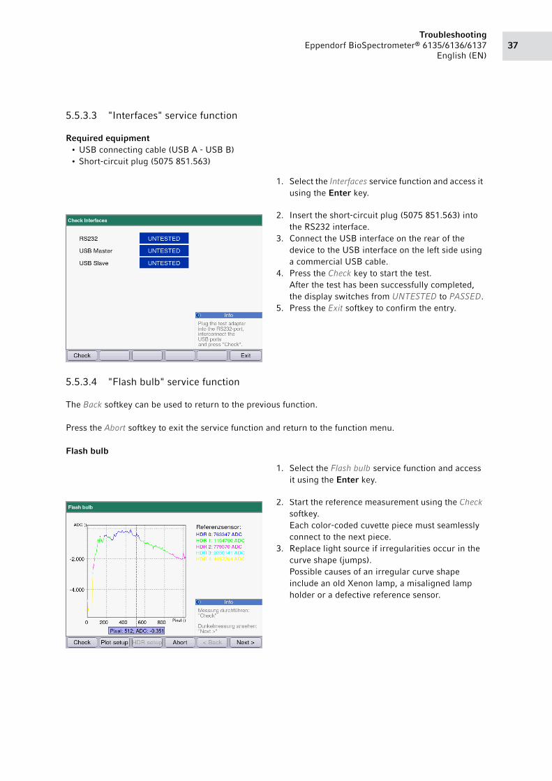
5.5.3.3 "Interfaces" service function
Required equipment• USB connecting cable (USB A - USB B)
• Short-circuit plug (5075 851.563)
5.5.3.4 "Flash bulb" service function
The Back softkey can be used to return to the previous function.
Press the Abort softkey to exit the service function and return to the function menu.
Flash bulb
1. Select the Interfaces service function and access it
using the Enter key.
2. Insert the short-circuit plug (5075 851.563) into
the RS232 interface.
3. Connect the USB interface on the rear of the
device to the USB interface on the left side using
a commercial USB cable.
4. Press the Check key to start the test.
After the test has been successfully completed,
the display switches from UNTESTED to PASSED.
5. Press the Exit softkey to confirm the entry.
1. Select the Flash bulb service function and access
it using the Enter key.
2. Start the reference measurement using the Check
softkey.
Each color-coded cuvette piece must seamlessly
connect to the next piece.
3. Replace light source if irregularities occur in the
curve shape (jumps).
Possible causes of an irregular curve shape
include an old Xenon lamp, a misaligned lamp
holder or a defective reference sensor.

TroubleshootingEppendorf BioSpectrometer® 6135/6136/6137
English (EN)38
Dark measurement
Intensity test
Raw data
Dark current subtracted
4. Press the Next> softkey to switch the dark
measurement.
5. Start the dark measurement using the Check
softkey.
Two straight lines can be seen in the diagram if
no stray light enters the device.
Stray light or a missing light guide plate create
two curve shapes in the diagram.
6. Press the Next> softkey to switch to the intensity
tests.
7. Select the Raw data service function and start the
measurement using the Check key.
This help function shows the device's
unprocessed measurement data in the diagram. It
is used for the error search during development.
8. Select the Subtract dark current service function
and start the measurement using the Check key.
This help function shows the result of the
calculation of the raw data and dark current data.
It is used for the error search during
development.

39Troubleshooting
Eppendorf BioSpectrometer® 6135/6136/6137
English (EN)
Reference value incl.
Fully incl. in calc.
Distribution test
Average value
9. Select the Reference incl. in calc. service function
and start the measurement using the Check key.
This help function shows the result of the
calculation of the raw data, dark current data and
reference sensor data. It is used for the error
search during development.
10.Select the Fully incl. in calc service function and
start the measurement using the Check key.
This help function shows the logarithm of the
calculation of the raw data, dark current data and
reference sensor data. It is used for the error
search during development.
11.Press the Next> softkey to switch to the
distribution test.
12.Select the Average value service function and
start the measurement using the Check key.
This help function shows the average value of
several repetitions of a measurement. The
number of repetitions can be preset in the entry
field. It is used for the error search during
development.

TroubleshootingEppendorf BioSpectrometer® 6135/6136/6137
English (EN)40
RMS value
Min/max value
Abbreviations• HDR= high dynamic range (high contrast)
• ADC= Xenon flashes
• RMS= root mean square (effective value)
The RMS value of a series of values (or continuous signal) is the square root of the arithmetic mean
(average) of the squares of the original values (or the square of the function that defines the continuous
waveform).
5.5.3.5 "Buzzer" service function
The buzzer emits a signal tone.
13.Select the RMS value service function and start
the measurement using the Check key.
This help function shows the scattering (noise)
after several repetitions of a measurement. The
number of repetitions can be preset in the entry
field. It is used for the error search during
development.
14.Select the Min/max value service function and
start the measurement by pressing the Check
key.
This help function shows the minimum and
maximum measured values after a measurement
has been repeated several times. The number of
repetitions can be preset in the entry field. It is
used for the error search during development.
Select the Buzzer service function and access it
using the Enter key.

41Troubleshooting
Eppendorf BioSpectrometer® 6135/6136/6137
English (EN)
5.5.4 "Software" subgroup
5.5.4.1 "Update" service function
Prerequisites
A prepared USB stick must be available. (see Updating the device software on p. 79)
Switch to the Software subdirectory in the Sub
Groups column.
1. Select the Update service function and access it
using the Enter key.
The "Update" screen appears.
Follow the instructions shown on the display.

TroubleshootingEppendorf BioSpectrometer® 6135/6136/6137
English (EN)42
5.5.4.2 "Reset factory settings" service function
5.5.4.3 "Backup" or "Restore" service function
1. Select the Reset factory settings service function
and access it using the Enter key.
2. Press the Yes softkey to reset the factory settings.
This will not delete the calibration data
(temperature alignment).
3. Follow the instructions on the display.
The No softkey cancels the process.
1. Select the Backup/Restore service function and
access it using the Enter key.
2. Select data backup using the Backup softkey or
restore the data using the Restore softkey.
3. Follow the instructions in the information field.
4. Start the backup process using the Backup
softkey.
5. Start restoring the data using the Restore softkey.

43Troubleshooting
Eppendorf BioSpectrometer® 6135/6136/6137
English (EN)
5.5.5 "Information" subgroup
5.5.5.1 "Device information" service function
After replacing the printed circuit board or Xenon lamp, the corresponding data must be corrected at this
location.
Entry of serial number and number of lamp flashes after replacing the printed circuit board
Switch to the Information subdirectory in the Sub
Groups column.
Note the displayed number of lamp flashes before replacing the printed circuit board.
Select the Device information customer service
function and access it using the Enter key.
The serial number of the device is located on the name plate. The name plate is located on the
rear side of the device.
The numeric keys are allocated with both letters and digits. Press the numeric keys until the
required letter or number is marked. The selection appear in the display field after a short
period of time.
Enter the serial number of the device and the
noted number of lamp flashes in the
corresponding fields.

TroubleshootingEppendorf BioSpectrometer® 6135/6136/6137
English (EN)44
Resetting the number of lamp flashes
Prerequisites
The Xenon lamp has been replaced.
Exporting device information
Switch to the lamp flash display.
Press the zero numeric key.
Press the Save softkey to save the device
information in the BioSpectrometer.
The data will be saved and the function menu will
then be shown in the display.
Press the Export key to start the export process.
Observe the instructions in the information window.
Select the storage medium and confirm it using
the Enter key.
Press the Export softkey to save the device
information.
The device information will be written to a file
named "BioSpectrometerDeviceInfo.txt" and
saved on the selected medium.
The Cancel softkey cancels the export process.

45Troubleshooting
Eppendorf BioSpectrometer® 6135/6136/6137
English (EN)
5.5.5.2 "Logfile" service function
Exporting the logfile
5.5.5.3 "Self test result" service function
1. Select the Self test result service function and access it using the Enter key.
The results of the self test routines are displayed.
Select the Logfile service function and access it
using the Enter key.
Press Page dn softkey to see the next page.
Press Page up softkey to see the previous page.
Press the Export key to start the export process.
Observe the instructions in the information window.
Select the storage medium and confirm it using
the Enter key.
Press the Export softkey to save the logfile.
The logfile will be written to a file named
"user.log" and saved on the selected medium.
The content of this file must be displayed using a
word processing program, e.g., WordPad.
The Cancel softkey cancels the export process.

TroubleshootingEppendorf BioSpectrometer® 6135/6136/6137
English (EN)46
5.5.6 "Adjustment" subgroup
5.5.6.1 "Optical adjustment" service function
Prerequisites
The liquid filter must be tempered before the adjustment to room temperature.
Prerequisites
The cuvette shaft must be empty before the HDR factor measurement.
Switch to the Adjustment subdirectory in the Sub
Groups column.
Observe the instructions in the material safety data sheets for the holmium filter and
didymium filter. The material safety data sheets can be found on the
http://www.eppendorf-support.com website.
Every time it is assembled, the device must be adjusted using the "Optical adjustment" service
function.
1. Select the Optical adjustment customer service
function and access it using the Enter key.
47Troubleshooting
Eppendorf BioSpectrometer® 6135/6136/6137
English (EN)
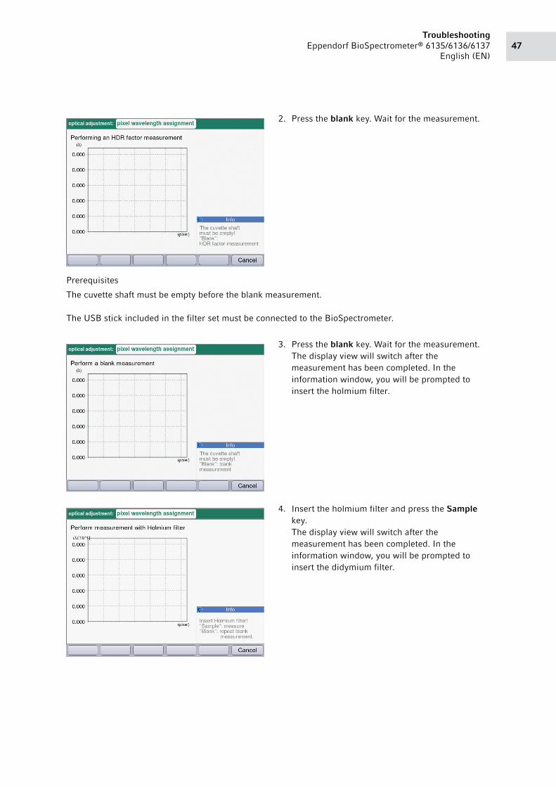
Prerequisites
The cuvette shaft must be empty before the blank measurement.
The USB stick included in the filter set must be connected to the BioSpectrometer.
2. Press the blank key. Wait for the measurement.
3. Press the blank key. Wait for the measurement.
The display view will switch after the
measurement has been completed. In the
information window, you will be prompted to
insert the holmium filter.
4. Insert the holmium filter and press the Sample
key.
The display view will switch after the
measurement has been completed. In the
information window, you will be prompted to
insert the didymium filter.

TroubleshootingEppendorf BioSpectrometer® 6135/6136/6137
English (EN)48
5.5.6.2 "Intensity adjustment" service function
Select the Intensity adjustment service function and access it using the Enter key.
The display for optical adjustment appears.
The following description applies to the following devices:
5. Insert the didymium filter and press the Sample
key.
6. Press the OK softkey to end the alignment after
the last measurement.
Device As of serial number
BioSpectrometer basic 6135CL601321
BioSpectrometer kinetic 6136CJ601387
BioSpectrometer fluorescence 6137CJ701337
BioPhotometer D30 6133CL400223
All repaired devices with a new mirror
(6135 866.103).
–

49Troubleshooting
Eppendorf BioSpectrometer® 6135/6136/6137
English (EN)
For older devices with the mirror 6135 866.006, the following settings apply:
Intensity• The display continuously shows the light
intensity of the sensors.
• One peak from the spectrum is shown in
addition to the intensity of the reference sensor.
• The upper bar shows the intensity of the current
measurement and the lower bar shows the
maximum intensity since the function was
accessed.
• Peak 2 must have an intensity of at least 29%.
• The spectrum (green) may not exceed the red
saturation line.
• The tip of Peak 2, marked in black, must be on
the green reference line.
Intensity• The display continuously shows the light
intensity of the sensors.
• Two peaks from the spectrum were shown in
addition to the intensity of the reference sensor.
• To guarantee correct operation of the
BioSpectrometer, Peak 1 and the reference
sensor must have an intensity of at least 40%.
• The upper bar shows the intensity of the current
measurement and the lower bar shows the
maximum intensity since the function was
accessed.
• Peak 2 must have an intensity of at least 29%.
• The spectrum (green) may not exceed the red
saturation line.
• The tip of Peak 2, marked in black, must be on
the green reference line.

TroubleshootingEppendorf BioSpectrometer® 6135/6136/6137
English (EN)50
5.5.6.3 "Thermal adjustment" service function
This function is only available on the BioSpectrometer kinetic.
For the BioSpectrometer kinetic 6136, use the temperature validation system MC/MC ep
(order no. 0055 000.298) and the corresponding temperature sensor (order no.
6135 870.003).
You will receive additional information for the measurement process in the information
window.
1. Select the Thermal adjustment service function
and access it using the Enter key.
2. Insert the temperature adapter in the cuvette
shaft.
3. Guide the measurement lead to the front side of
the BioSpectrometer.
4. Connect the temperature sensor to the Testo
thermometer.
5. Select the temperature to be calibrated and
adjusted.
6. Press the Start softkey.
7. Wait for the measurement.
The text "Tempering..." appears during the
measurement; the text switches to "Ready" as
soon as the measurement has been completed.
8. Read off the temperature from the Testo
thermometer, enter it in the selected field and
confirm it using the Enter key.
Press the Abort softkey to exit the function and
return to the function menu.
9. Carry out the adjustment again for the other four
temperatures.

51Troubleshooting
Eppendorf BioSpectrometer® 6135/6136/6137
English (EN)
5.5.6.4 "Continuous flashing" service function
This function is to be used, if necessary, to adjust the light path.
5.6 Customer service functions
5.6.1 Navigation
1. Use the up and down arrow keys to select the entries in a column (groups, functions).
2. Use the left and right arrow keys to switch from one column to another.
5.6.2 Activating customer service functions
Proceed as follows to activate the customer service functions:
Prerequisites
Situation 1: The device is switched off.
You want to switch on the device and immediately access the customer service functions.
Continue with Item 3 if you would like to switch from the service functions to the customer service
functions (situation 2).
Select the Continuous flashing service function
and access it using the Enter key.
The Xenon lamp flashes continuously.

TroubleshootingEppendorf BioSpectrometer® 6135/6136/6137
English (EN)52
Prerequisites
Situation 2: You would like to switch from the service functions to customer service functions.
5.6.3 "Device settings" subgroup
1. Switch the BioSpectrometer on.
2. Press the Function softkey.
The display with the customer service functions
appears.
3. Switch to the main directory.
4. Select the User entry.
Switch to the Device settings subdirectory in the
Sub Groups column.

53Troubleshooting
Eppendorf BioSpectrometer® 6135/6136/6137
English (EN)
5.6.3.1 "Settings" customer service function
Select language
Prerequisites
The field for the language selection is highlighted in color.
Selecting the self test interval
1. Select the Settings customer service function and
access it using the Enter key.
2. Open the field for the language selection using
the Enter key.
The field becomes a list with several entries.
3. Select the required language from the list.
4. Press the Save softkey to adopt the selection.
5. Then turn the device off and back on to switch the
display texts to the selected language.
Press the Cancel softkey to exit the device
settings and return to the function menu.
6. Select the selection field for the self test interval.
7. Open the selection field using the Enter key.
8. Select the required interval from the list.
9. Press the Save softkey to adopt the selection.
Press the Cancel softkey to exit the device
settings and return to the function menu.
A description of how to correct the date and time can be found in the operating manual.

TroubleshootingEppendorf BioSpectrometer® 6135/6136/6137
English (EN)54
5.6.4 "Device calibration" subgroup
5.6.4.1 "Spectrometer unit" customer service function
Check wavelength accuracy
Switch to the Device calibration subdirectory in
the Sub Groups column.
For this function test, you will need the BioSpectrometer customer reference filter set (order
no. 6135 928.001) or service test filter set (order no. 6135 931.002).
1. Select the Spectrometer unit customer service
function and access it using the Enter key.
2. Select the Check wavelength systematic error
function and activate it using the Enter key.
3. Press the Next> softkey.
Press the Abort softkey to exit the function and
return to the function menu.

55Troubleshooting
Eppendorf BioSpectrometer® 6135/6136/6137
English (EN)
Check photometric accuracy
Prerequisites
The Spectrometer unit customer service function has been accessed.
4. Insert the A0 blank filter in the cuvette shaft and
press the blank key. Wait for the measurement.
5. Insert the 260 nm test filter in the cuvette shaft
and press the Sample key. Wait for the
measurement.
6. Repeat the measurement with the 280 nm and
800 nm test filters.
The last measurement can be repeated using the
<Back softkey.
Press the Abort softkey to exit the function and
return to the function menu.
After all measurements have been completed, the
measured values for the three wavelengths are
shown in the display.
7. Compare the measured values to the limiting
values in the provided filter set table.
An error analysis must be completed if a
measured value is outside of the range of limiting
values.
8. Press the Finish softkey to return to the
"Spectrometer unit" customer service function.
9. Select the Check photometric accuracy function
and activate it using the Enter key.
10.Press the Next> softkey.
Press the Abort softkey to exit the function and
return to the function menu.

TroubleshootingEppendorf BioSpectrometer® 6135/6136/6137
English (EN)56
5.6.4.2 "Temperature unit" customer service function
Prerequisites
The cuvette shaft must be empty.
11.Insert the A0 blank filter in the cuvette shaft and
press the blank key. Wait for calibration to be
completed.
12.Insert the A1 test filter in the cuvette shaft and
press the Sample key. Wait for calibration to be
completed.
13.Repeat calibration with the test filters A2 and A3.
The last measurement can be repeated using the
<Back softkey.
Press the Abort softkey to exit the function and
return to the function menu.
The device measures the test filter 15 times at
nine wavelengths. Average values and variation
coefficients of the measurement series can then
be read in the display.
The list of measured values can be moved using
the arrow keys.
14.Compare the average values and variation
coefficients to the limiting values in the table
provided.
If a measured value is outside of the limiting
values, the error must be analyzed and corrected.
15.Press the Finish softkey to return to the
"Spectrometer unit" customer service function.
1. Select the Temperature unit customer service
function and access it using the Enter key.
2. Start the calibration using the Next> softkey.
The calibration of the five temperatures takes
approx. 30 minutes.
The estimated remaining time is displayed during
calibration.
Press the Abort softkey to exit the function and
return to the function menu.

57Troubleshooting
Eppendorf BioSpectrometer® 6135/6136/6137
English (EN)
5.6.4.3 "Temperature unit" customer service function with an external temperature tester
The internal temperature measurement can be tested using an external measuring device.
3. Check the status of the cuvette shaft temperature
control.
An error analysis must be completed if one or
more statuses are marked as "fail".
4. Press the Temperature unit softkey to return to
the "Spectrometer unit" customer service
function.
1. Insert the temperature measuring adapter in the
cuvette shaft.
2. Guide the measurement lead to the front side of
the BioSpectrometer.
3. Connect the temperature measuring adapter to
the Testo temperature tester.
4. Select the Temperature unit customer service
function and access it using the Enter key.
5. Start the calibration using the Next> softkey.
6. tempering... appears on the display when the
cuvette holder is being heated.
7. During vernier adjustment of the temperature,
checking... appears on the display.
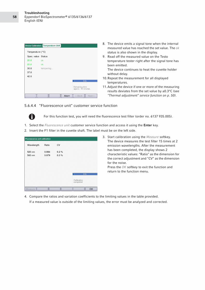
TroubleshootingEppendorf BioSpectrometer® 6135/6136/6137
English (EN)58
5.6.4.4 "Fluorescence unit" customer service function
1. Select the Fluorescence unit customer service function and access it using the Enter key.
2. Insert the F1 filter in the cuvette shaft. The label must be on the left side.
4. Compare the ratios and variation coefficients to the limiting values in the table provided.
If a measured value is outside of the limiting values, the error must be analyzed and corrected.
8. The device emits a signal tone when the internal
measured value has reached the set value. The ok
status is also shown in the display.
9. Read off the measured value on the Testo
temperature tester right after the signal tone has
been emitted.
The device continues to heat the cuvette holder
without delay.
10.Repeat the measurement for all displayed
temperatures.
11.Adjust the device if one or more of the measuring
results deviates from the set value by ±0.3°C (see
"Thermal adjustment" service function on p. 50).
For this function test, you will need the fluorescence test filter (order no. 6137 935.005).
3. Start calibration using the Measure softkey.
The device measures the test filter 15 times at 2
emission wavelengths. After the measurement
has been completed, the display shows 2
characteristic values: "Ratio" as the dimension for
the correct adjustment and "CV" as the dimension
for the noise.
Press the OK softkey to exit the function and
return to the function menu.

59Troubleshooting
Eppendorf BioSpectrometer® 6135/6136/6137
English (EN)
5.6.4.5 "Perform self test" customer service function
1. Select the Perform self test customer service function and access it using the Enter key.
The self test automatically elapses and shows the progress in the display.
2. Check the test result.
An error analysis must be completed if one or more of the results are marked as "fail".
3. Press the OK softkey to return to the "Perform self test" customer service function.

TroubleshootingEppendorf BioSpectrometer® 6135/6136/6137
English (EN)60
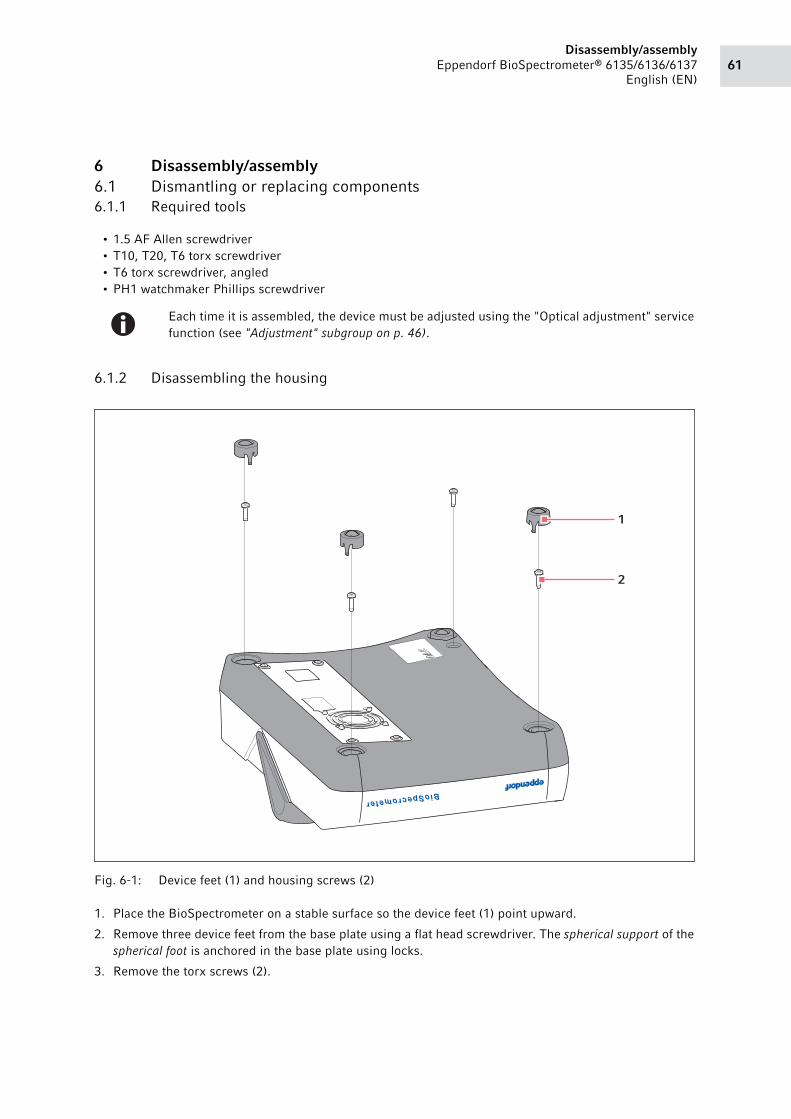
61Disassembly/assembly
Eppendorf BioSpectrometer® 6135/6136/6137
English (EN)
6 Disassembly/assembly6.1 Dismantling or replacing components
6.1.1 Required tools
• 1.5 AF Allen screwdriver
• T10, T20, T6 torx screwdriver
• T6 torx screwdriver, angled
• PH1 watchmaker Phillips screwdriver
6.1.2 Disassembling the housing
Abb. 6-1: Device feet (1) and housing screws (2)
Fig. 6-1: Device feet (1) and housing screws (2)
1. Place the BioSpectrometer on a stable surface so the device feet (1) point upward.
2. Remove three device feet from the base plate using a flat head screwdriver. The spherical support of the
spherical foot is anchored in the base plate using locks.
3. Remove the torx screws (2).
Each time it is assembled, the device must be adjusted using the "Optical adjustment" service
function (see "Adjustment" subgroup on p. 46).
BioSpecrometer
1
2

Disassembly/assemblyEppendorf BioSpectrometer® 6135/6136/6137
English (EN)62
4. Reinsert the device feet in the base plate.
5. Place the BioSpectrometer on the device feet.
6. Carefully lift the upper part of housing upward (cable connections) and place it next to the
BioSpectrometer.Abb. 6-2: Setting down the upper part of housing
Fig. 6-2: Setting down the upper part of housing
6.1.3 Replacing the lamp with the lamp holder
Prerequisites
The upper part of the housing has been removed.
Abb. 6-3: Adjustment tool (1) on the lamp holder
Fig. 6-3: Adjustment tool (1) on the lamp holder
23
45
6
78
9
kin
eti
c
Bio
Sp
ect
rom
ete
r
1

63Disassembly/assembly
Eppendorf BioSpectrometer® 6135/6136/6137
English (EN)
1. Screw the adjustment tool (1) for the lamp holder (order no. 6135 868.009) on to the housing using two
screws from the EMC shielding plate.
To lock the position of the lamp holder, the adjustment tool must be placed form-locking on the lamp
holder.
2. Remove the reference diode plug
3. Pos. 2) from the PCB sensor.
4. Carefully remove the reference diode cable from the cable routing.Abb. 6-4: EMC shielding plate (2) on the lamp holder
Fig. 6-4: EMC shielding plate (2) on the lamp holder
5. Unscrew the EMC shielding plate (2) (three T10 torx screws (1)).Abb. 6-5: Lamp holder (1) with connections (2, 3)
Fig. 6-5: Lamp holder (1) with connections (2, 3)
6. Remove the plug (3) for the Xenon lamp power supply from the PCB BioSpectrometer.
7. Unscrew the lamp holder (1) (three T10 torx screws).
8. Replace the old lamp holder with a new one.
9. Place the new lamp holder form-locking on the adjustment tool and screw it down.
10.Connect the Xenon lamp to the power supply on the PCB BioSpectrometer.
11.Insert the reference diode plug in the PCB sensor.
12.Screw down the EMC shielding plate.
13.Attach the upper housing part.
14.Check the intensity using the "Intensity adjustment" service function (see "Intensity adjustment" service
function on p. 48).
2
1
1
23

Disassembly/assemblyEppendorf BioSpectrometer® 6135/6136/6137
English (EN)64
15.Screw down the upper part of housing.
16.Carry out the "Optical adjustment" service function (see "Adjustment" subgroup on p. 46).
17.Check the wavelength systematic error and photometric accuracy (see "Spectrometer unit" customer
service function on p. 54).
18.Set the flash counter to zero (see "Device information" service function on p. 43).
6.1.4 Replacing the PCB BioSpectrometer
Prerequisites
The upper part of the housing has been removed.
1. Unscrew the EMC shielding plate (three T10 torx screws).
2. Remove all plugs from the PCB BioSpectrometer.
3. Remove the screws that are used to fasten the PCB BioSpectrometer (seven T10 torx screws).
4. Replace the old PCB BioSpectrometer with a new PCB BioSpectrometer.
5. Screw down the new PCB BioSpectrometer.
6. Insert all plugs, which were previously removed, in the new PCB BioSpectrometer.Abb. 6-6: Binding together the connecting cables
Fig. 6-6: Binding together the connecting cables
7. Bind together the connecting cables from the switching power supply unit to the PCB BioSpectrometer
with the tie wraps.
8. Screw down the EMC shielding plate.
9. Attach the upper housing part.
10.Check the intensity using the "Intensity adjustment" service function (see "Intensity adjustment" service
function on p. 48).
11.Screw down the upper part of housing.
12.Carry out the "Optical adjustment" service function (see "Adjustment" subgroup on p. 46).
13.Check the wavelength systematic error and photometric accuracy (see "Spectrometer unit" customer
service function on p. 54).
14.Enter the number of lamp flashes and serial number of the BioSpectrometer (see "Device information"
service function on p. 43).
Note the counter reading of the lamp flash. The counter reading must be saved in the new
PCB BioSpectrometer (see "Device information" service function on p. 43) following the
replacement.
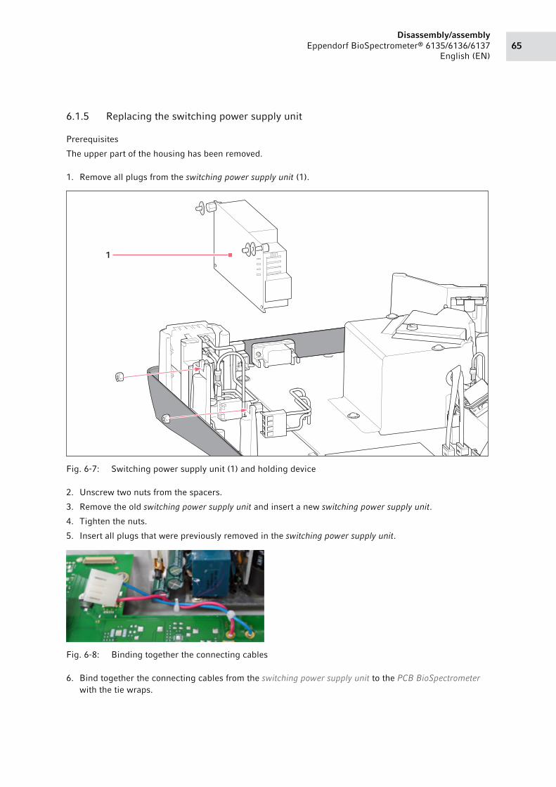
65Disassembly/assembly
Eppendorf BioSpectrometer® 6135/6136/6137
English (EN)
6.1.5 Replacing the switching power supply unit
Prerequisites
The upper part of the housing has been removed.
1. Remove all plugs from the switching power supply unit (1).Abb. 6-7: Switching power supply unit (1) and holding device
Fig. 6-7: Switching power supply unit (1) and holding device
2. Unscrew two nuts from the spacers.
3. Remove the old switching power supply unit and insert a new switching power supply unit.
4. Tighten the nuts.
5. Insert all plugs that were previously removed in the switching power supply unit.Abb. 6-8: Binding together the connecting cables
Fig. 6-8: Binding together the connecting cables
6. Bind together the connecting cables from the switching power supply unit to the PCB BioSpectrometer
with the tie wraps.
1

Disassembly/assemblyEppendorf BioSpectrometer® 6135/6136/6137
English (EN)66
7. Attach and tighten the upper part of housing.
8. Carry out the "Optical adjustment" service function (see "Adjustment" subgroup on p. 46).
9. Check the wavelength systematic error and photometric accuracy (see "Spectrometer unit" customer
service function on p. 54).
6.1.6 Replacing the display
Prerequisites
The upper part of the housing has been removed.
1. Remove the display cable on the PCB BioSpectrometer.
2. Unscrew the display holder and display from the upper part of housing (three T20 torx screws).
3. Unscrew the display holder from the display (four T10 torx screws).
4. Replace the old display with the new display.
5. Screw down the display holder on the new display.
6. Center the Display and display holder in the housing window and tighten it.
7. Attach and tighten the upper part of housing.
8. Test the display (see "Display" service function on p. 36).
9. Carry out the "Optical adjustment" service function (see "Adjustment" subgroup on p. 46).
6.1.7 Replacing the keypad
Prerequisites
The upper part of the housing has been removed.
1. Remove the keypad ribbon cable on the PCB BioSpectrometer.
2. Remove the bonded grounding strip from the upper part of housing.
3. Remove the bonded keypad from the upper part of housing. The keypad is mounted to the upper part of
housing using double-sided adhesive tape.
4. Remove tape residue using a suitable solvent.
5. Use grounding strip to bond the new keypad.
6. Attach the ribbon cable to the PCB Biospectrometer.
7. Attach and tighten the upper part of housing.
8. Test the keypad (see "Display" service function on p. 36).
9. Carry out the "Optical adjustment" service function (see "Adjustment" subgroup on p. 46).
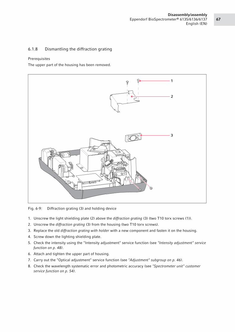
67Disassembly/assembly
Eppendorf BioSpectrometer® 6135/6136/6137
English (EN)
6.1.8 Dismantling the diffraction grating
Prerequisites
The upper part of the housing has been removed.
Abb. 6-9: Diffraction grating (3) and holding device
Fig. 6-9: Diffraction grating (3) and holding device
1. Unscrew the light shielding plate (2) above the diffraction grating (3) (two T10 torx screws (1)).
2. Unscrew the diffraction grating (3) from the housing (two T10 torx screws).
3. Replace the old diffraction grating with holder with a new component and fasten it on the housing.
4. Screw down the lighting shielding plate.
5. Check the intensity using the "Intensity adjustment" service function (see "Intensity adjustment" service
function on p. 48).
6. Attach and tighten the upper part of housing.
7. Carry out the "Optical adjustment" service function (see "Adjustment" subgroup on p. 46).
8. Check the wavelength systematic error and photometric accuracy (see "Spectrometer unit" customer
service function on p. 54).
3
2
1
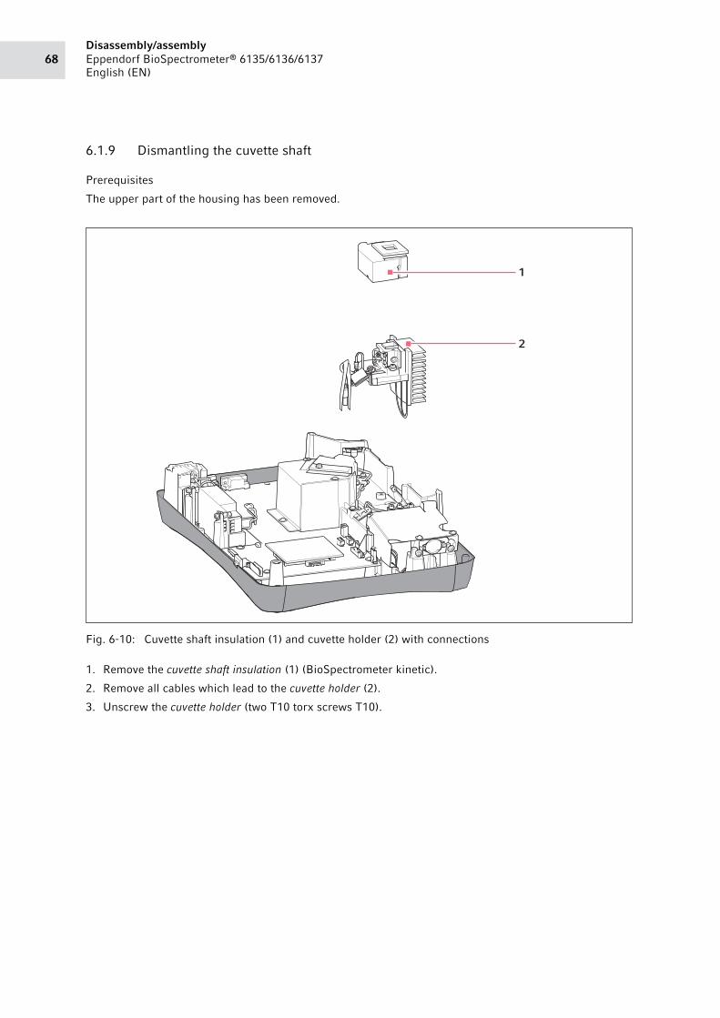
Disassembly/assemblyEppendorf BioSpectrometer® 6135/6136/6137
English (EN)68
6.1.9 Dismantling the cuvette shaft
Prerequisites
The upper part of the housing has been removed.
Abb. 6-10: Cuvette shaft insulation (1) and cuvette holder (2) with connections
Fig. 6-10: Cuvette shaft insulation (1) and cuvette holder (2) with connections
1. Remove the cuvette shaft insulation (1) (BioSpectrometer kinetic).
2. Remove all cables which lead to the cuvette holder (2).
3. Unscrew the cuvette holder (two T10 torx screws T10).
1
2
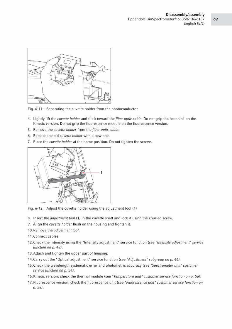
69Disassembly/assembly
Eppendorf BioSpectrometer® 6135/6136/6137
English (EN)
Abb. 6-11: Separating the cuvette holder from the photoconductor
Fig. 6-11: Separating the cuvette holder from the photoconductor
4. Lightly lift the cuvette holder and tilt it toward the fiber optic cable. Do not grip the heat sink on the
Kinetic version. Do not grip the fluorescence module on the fluorescence version.
5. Remove the cuvette holder from the fiber optic cable.
6. Replace the old cuvette holder with a new one.
7. Place the cuvette holder at the home position. Do not tighten the screws.Abb. 6-12: Adjust the cuvette holder using the adjustment tool (1)
Fig. 6-12: Adjust the cuvette holder using the adjustment tool (1)
8. Insert the adjustment tool (1) in the cuvette shaft and lock it using the knurled screw.
9. Align the cuvette holder flush on the housing and tighten it.
10.Remove the adjustment tool.
11.Connect cables.
12.Check the intensity using the "Intensity adjustment" service function (see "Intensity adjustment" service
function on p. 48).
13.Attach and tighten the upper part of housing.
14.Carry out the "Optical adjustment" service function (see "Adjustment" subgroup on p. 46).
15.Check the wavelength systematic error and photometric accuracy (see "Spectrometer unit" customer
service function on p. 54).
16.Kinetic version: check the thermal module (see "Temperature unit" customer service function on p. 56).
17.Fluorescence version: check the fluorescence unit (see "Fluorescence unit" customer service function on
p. 58).
1

Disassembly/assemblyEppendorf BioSpectrometer® 6135/6136/6137
English (EN)70
6.1.10 Replacing the fiber optic cable
Prerequisites
The upper part of the housing has been removed.
1. Unscrew the torx set screw (T6) on the fiber optic cable holder.Abb. 6-13: Cuvette shaft insulation (1) and cuvette holder (2) with connections
Fig. 6-13: Cuvette shaft insulation (1) and cuvette holder (2) with connections
2. Remove the cuvette shaft insulation (1) (BioSpectrometer kinetic).
3. Remove all cables which lead to the cuvette holder (2).
4. Unscrew the cuvette holder (two T10 torx screws T10).
5. Lightly lift the cuvette holder and tilt it toward the fiber optic cable. Do not grip the heat sink on the
Kinetic version.
6. Remove the fiber optic cable from the cuvette holder.
7. Remove the fiber optic cable from the second opposite facing holder.
8. Replace the old fiber optic cable with a new one.
9. Insert the new fiber optic cable in the two holders.
10.Place the cuvette holder at the home position. Do not tighten the screws.
11.Insert the adjustment tool in the cuvette shaft and lock it using the knurled screw.
12.Align and tighten the cuvette holder.
1
2

71Disassembly/assembly
Eppendorf BioSpectrometer® 6135/6136/6137
English (EN)
13.Remove the adjustment tool.
14.Connect cables.
15.Check the intensity using the "Intensity adjustment" service function (see "Intensity adjustment" service
function on p. 48).
16.Attach and tighten the upper part of housing.
17.Carry out the "Optical adjustment" service function (see "Adjustment" subgroup on p. 46).
18.Check the wavelength systematic error and photometric accuracy (see "Spectrometer unit" customer
service function on p. 54).

Disassembly/assemblyEppendorf BioSpectrometer® 6135/6136/6137
English (EN)72
6.1.11 Replacing the PCB photo diode array
Prerequisites
The upper part of the housing has been removed.
Abb. 6-14: Light shielding plate (2) above the photo diode array and PCB photo diode array (3)
Fig. 6-14: Light shielding plate (2) above the photo diode array and PCB photo diode array (3)
1. Unscrew the light shielding plate (2) above the photo diode array (two T10 torx screws (1)).
2. Remove the cable from the PCB photo diode array (3).
Never loosen the two torx screws (1). Loosening these screws causes a misalignment of the
photo diode array, which can only be corrected by the manufacturer.
1
1
2
3
4
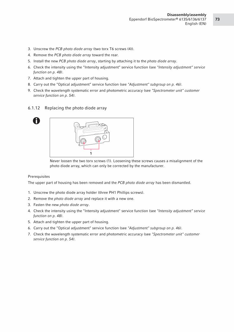
73Disassembly/assembly
Eppendorf BioSpectrometer® 6135/6136/6137
English (EN)
3. Unscrew the PCB photo diode array (two torx T6 screws (4)).
4. Remove the PCB photo diode array toward the rear.
5. Install the new PCB photo diode array, starting by attaching it to the photo diode array.
6. Check the intensity using the "Intensity adjustment" service function (see "Intensity adjustment" service
function on p. 48).
7. Attach and tighten the upper part of housing.
8. Carry out the "Optical adjustment" service function (see "Adjustment" subgroup on p. 46).
9. Check the wavelength systematic error and photometric accuracy (see "Spectrometer unit" customer
service function on p. 54).
6.1.12 Replacing the photo diode array
Prerequisites
The upper part of housing has been removed and the PCB photo diode array has been dismantled.
1. Unscrew the photo diode array holder (three PH1 Phillips screws).
2. Remove the photo diode array and replace it with a new one.
3. Fasten the new photo diode array.
4. Check the intensity using the "Intensity adjustment" service function (see "Intensity adjustment" service
function on p. 48).
5. Attach and tighten the upper part of housing.
6. Carry out the "Optical adjustment" service function (see "Adjustment" subgroup on p. 46).
7. Check the wavelength systematic error and photometric accuracy (see "Spectrometer unit" customer
service function on p. 54).
Never loosen the two torx screws (1). Loosening these screws causes a misalignment of the
photo diode array, which can only be corrected by the manufacturer.
1

Disassembly/assemblyEppendorf BioSpectrometer® 6135/6136/6137
English (EN)74
6.1.13 Replacing the mirror
Abb. 6-15: Mirror holder (1) and mirror (2)
Fig. 6-15: Mirror holder (1) and mirror (2)
Prerequisites
The upper part of the housing has been removed.
Abb. 6-16: Handling the tweezers for loosening the mirror holder
Fig. 6-16: Handling the tweezers for loosening the mirror holder
1. Loosen the mirror holder lock using angled tweezers while removing the mirror holder (1) using straight
tweezers (see figure).
2. Remove the old mirror (2) and insert the new mirror.
1
2
75Disassembly/assembly
Eppendorf BioSpectrometer® 6135/6136/6137
English (EN)
3. If the mirror holder has become too damaged during removal, replace the old mirror holder with a new
one.
4. Place the mirror holder on the mirror and lock it.
5. Check the intensity using the "Intensity adjustment" service function (see "Intensity adjustment" service
function on p. 48).
6. Attach and tighten the upper part of housing.
7. Carry out the "Optical adjustment" service function (see "Adjustment" subgroup on p. 46).
8. Check the wavelength systematic error and photometric accuracy (see "Spectrometer unit" customer
service function on p. 54).
6.1.14 Disassembling the fan
(Only BioSpectrometer kinetic)
Prerequisites
The upper part of the housing has been removed.
1. Remove the fan plug (X21) from the PCB BioSpectrometer.
2. Unscrew the light shielding plate above the diffraction grating (two T10 torx screws).
3. Remove the retaining plate of the fan on the base of the BioSpectrometer (four PH1 Phillips screws).
4. Replace the old fan with a new one.
5. Screw down the fastening plate of the fan.
6. Check the fan function using the "Temperature unit" customer service function (see "Temperature unit"
customer service function on p. 56).
7. Attach and tighten the upper part of housing.
8. Carry out the "Optical adjustment" service function (see "Adjustment" subgroup on p. 46).
9. Check the wavelength systematic error and photometric accuracy (see "Spectrometer unit" customer
service function on p. 54).

Disassembly/assemblyEppendorf BioSpectrometer® 6135/6136/6137
English (EN)76

77Alignment/adjustment
Eppendorf BioSpectrometer® 6135/6136/6137
English (EN)
7 Alignment/adjustment7.1 Adjustment
7.1.1 Required tools
• 1.5 AF Allen screwdriver
• T10, T20, T6 torx screwdriver
• Blackout cloth (http://www.thorlabs.de/NewGroupPage9.cfm?ObjectGroup_ID=190)
7.1.2 Adjusting the diffraction grating
Prerequisites
The upper part of the housing has been removed.
1. Switch on the device and activate the service functions (see Activating service functions on p. 34).
2. Access the "Intensity adjustment" service function (see "Intensity adjustment" service function on p. 48).
Prerequisites
The light shielding plate has been mounted.
3. Loosen the screws on the diffraction grating (two T10 torx screws).
4. Place the diffraction grating on the stop.
5. Slowly adjust the diffraction grating by alternately tightening the screws until the specifications of the
"Intensity adjustment" service function are met (see "Intensity adjustment" service function on p. 48).
6. Tighten the screws on the diffraction grating.
7. Attach and screw on the upper part of the housing.
8. Carry out the "Optical adjustment" service function (see "Adjustment" subgroup on p. 46).
9. Check the wavelength systematic error and photometric accuracy (see "Spectrometer unit" customer
service function on p. 54).
Each time the device is assembled, it must be adjusted using the "Optical adjustment" service
function (see "Adjustment" subgroup on p. 46).
Observe the information in the safety data sheets for the holmium and didymium filter
(MSDS). The material safety data sheets can be found on the
http://www.eppendorf-support.com website.
To facilitate adjustment when the device is open, the area below the light shielding plate must
be covered with a blackout cloth.

Alignment/adjustmentEppendorf BioSpectrometer® 6135/6136/6137
English (EN)78
7.1.3 Adjusting the fiber-optic cable
The process of adjusting the fiber-optic cable consists of two separate steps which refer to two different
points in the device. The two steps mutually influence each other and must be performed several times on
an alternating basis. Peak 1 and the reference sensor must have an intensity of at least 40%. Peak 2 must
have an intensity of at least 29%.
Prerequisites
The upper part of the housing has been removed.
1. Switch on the device and activate the service functions (see Activating service functions on p. 34).
2. Access the "Intensity adjustment" service function (see "Intensity adjustment" service function on p. 48).
Step 1
3. Loosen the set screw on the fiber-optic cable holder (T6 torx set screw).
4. Turn the metallic holder of the glass fiber using a pair of tweezers.
The value of peak 1 changes. The value must reach a maximum, but must not exceed the red saturation
line.
5. Tighten the set screw on the fiber-optic cable.
Step 2
6. Loosen the screws on the fiber-optic cable holder (two T10 torx screws).
7. Slowly move the holder to the left and right by moving a screwdriver in the bore of the holder to the left
and right.
The value of peak 1 changes. The value must reach a maximum, but must not exceed the red saturation
line.
8. Tighten the screws on the fiber-optic cable holder.
9. Repeat step 1 and 2 until the value of peak 1 reaches at least 40%.
10.Attach and screw on the upper part of the housing.
11.Carry out the "Optical adjustment" service function (see "Adjustment" subgroup on p. 46).
12.Check the wavelength systematic error and photometric accuracy (see "Spectrometer unit" customer
service function on p. 54).

79Software
Eppendorf BioSpectrometer® 6135/6136/6137
English (EN)
8 Software8.1 Updating the device software
Prerequisites
• USB stick with at least 1 GB of memory
• USB stick is formatted in FAT 32
• Computer with Windows XP or Windows 7 operating system
• Internet access
Downloading the software
1. Create a new folder on the computer and name it as desired.
2. Download the "support_X.X.X.X.zip" file from the www.eppendorf-support.com website to the
computer. Save the "support_X.X.X.X.zip" file in the folder just created on the computer.
Extracting software to the USB stick
3. Insert the USB stick in the computer.
4. Unzip the "support_X.X.X.X.zip" file on the connected USB stick.
5. If files with the same name already exist on the USB stick, these files will be overwritten.
The USB stick contains the following items:• "Eppendorf" folder
• "uImage-eco9g20k" file
6. Remove the USB from the computer.
Update the software on the BioSpectrometer
Prerequisites
The BioSpectrometer is switched off.
7. Connect the USB stick to the BioSpectrometer.
8. Switch on the BioSpectrometer.
The BioSpectrometer starts via the USB stick.
The display shows the software version installed on the device and the software version on the USB
stick.
9. Press the Continue softkey to confirm the software update.
You can cancel the process with the Cancel softkey.
The software installed on the device is replaced by the software from the USB stick.
"Update complete" is displayed when the update is complete.
Completing the update
10.Switch off the BioSpectrometer.
11.Disconnect the USB stick from the BioSpectrometer.

SoftwareEppendorf BioSpectrometer® 6135/6136/6137
English (EN)80
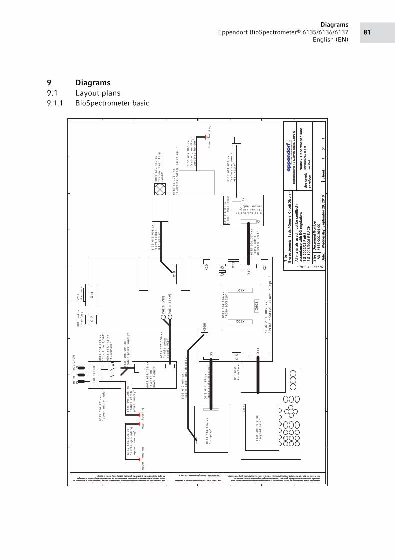
81Diagrams
Eppendorf BioSpectrometer® 6135/6136/6137
English (EN)
9 Diagrams9.1 Layout plans
9.1.1 BioSpectrometer basic
5 5
4 4
3 3
2 2
1 1
DD
CC
BB
AA
X1
7X
14
X1
9
X2
0 X1
2
X6
X7 X1
0 X2
1
X9
X1
5
X1
1X
60
3
X602
X601
X1
X2
61
35
6
08
.0
07
-x
x
"d
at
a
ca
bl
ed
et
ec
to
r
un
it
"
61
35
6
14
.0
07
-x
x
"r
ef
er
en
ce
s
en
so
rw
it
h
ca
bl
e"
61
35
6
15
.0
03
-x
x
"l
am
p
so
ck
et
wi
th
c
ab
le
"0
01
3
61
0.
41
0-
xx
"x
en
on
f
la
sh
l
am
pL
46
40
"
RS
23
2i
nt
er
fa
ce
US
B
de
vi
ce
in
te
rf
ac
e
US
B
ho
st
in
te
rf
ac
e
X9
00
00
13
6
14
.1
87
-x
x
"d
at
a
ca
bl
e
di
sp
la
y"
61
35
6
12
.0
04
-x
x
"c
ab
le
b
ac
kl
ig
ht
d
is
pl
ay
"
61
35
6
01
.0
10
-x
x
"k
ey
pa
d
ba
si
c"
PA
D2
(G
ND
)
PA
D1
(+
15
V)
61
35
6
07
.0
00
-x
x
"c
ab
le
p
ow
er
su
pp
ly
P
CB
A"
li
ne
f
il
te
r
ma
in
s
(1
00
V-
24
0V
)P
E
L
N 61
35
6
06
.0
04
-x
x
"c
ab
le
p
ow
er
s
up
pl
y"
61
35
6
05
.0
08
-x
x
"c
ab
le
e
ar
th
po
we
r
su
pp
ly
"
61
35
6
17
.0
06
-x
x
"c
ab
le
g
ro
un
di
ng
c
ue
ve
tt
e
ho
ld
er
"
61
35
6
16
.0
00
-x
x
"c
ab
le
g
ro
un
di
ng
up
pe
r
ho
us
in
g"
up
pe
r
ho
us
in
gl
ow
er
h
ou
si
ng
61
35
1
21
.0
51
-x
x
"c
ue
ve
tt
e
ho
ld
er
b
as
ic
c
pl
."
00
13
6
14
.1
81
-x
x
li
ne
ar
i
ma
ge
s
en
so
r
61
36
8
01
.0
05
-x
x
"P
CB
A
co
nt
ro
l
ki
ne
ti
c
cp
l.
"
00
13
6
14
.1
74
-x
x
"P
CB
A
EC
O9
G2
0"
6135 802.008-xx "linear imagesensor modul"
00
13
6
14
.1
86
-x
x
"d
is
pl
ay
"
00
13
6
14
.1
62
-x
x
"s
wi
tc
hi
ng
po
we
r
su
pp
ly
"
00
13
5
64
.2
13
-x
x
"2
x
f
us
e
2,
5A
T"
00
13
6
14
.1
71
-x
x
"p
ow
er
e
nt
ry
m
od
ul
"
00
13
6
14
.1
72
-x
x
"f
us
ed
ra
we
r"
lo
we
r
ho
us
in
g
basic
Ti tl
e
Siz
eD
ocum
ent N
umbe
r
Dat
e:S
heet
of
Nam
e /
Dep
a rtm
ent /
Dat
e
Ch. - No.:
cert
ified
:d e
sign
ed:
All
ma t
eria
l s u
sed
mus
t be
cer t
ifie d
in
a cco
rdan
c e w
it h E
G r
egul
a tio
nsE
G 2
002/
9 5 R
oHS
E
G 1
907/
2006
RE
AC
H
613 5
900
.204
-00
Bio
s pec
trom
e ter
Bas
ic /
Gen
eral
Circ
uit D
iagr
am
A3
11
Wed
nesd
a y, S
epte
mbe
r 29
, 201
0
Tim
mer
ma n
n / I
H-R
M
<Ch. - No.>
<cer
tifie
d >
Bar
khau
s enw
eg 1
/ 2 2
3 39
Ham
bur g
/ G
erm
any
Ti tl
e
Siz
eD
o cum
ent N
umbe
r
Dat
e :S
heet
of
Nam
e /
Dep
a rtm
ent /
Dat
e
Ch. - No.:
cert
ified
:d e
sign
ed:
All
ma t
eria
l s u
sed
mus
t be
cer t
ifie d
in
a cco
rdan
c e w
it h E
G r
egul
a tio
nsE
G 2
002/
9 5 R
oHS
E
G 1
907/
2006
RE
AC
H
613 5
900
.204
-00
Bio
s pec
trom
e ter
Bas
ic /
Gen
eral
Circ
uit D
iagr
am
A3
11
Wed
nesd
a y, S
epte
mbe
r 29
, 201
0
Tim
mer
ma n
n / I
H-R
M
<Ch. - No.>
<cer
tifie
d >
Bar
khau
s enw
eg 1
/ 2 2
3 39
Ham
bur g
/ G
erm
any
VERTRAULICH ! Schutzvermerk ISO 16016 beachten !
CONFIDENTIAL ! Copyright reserved ISO 16016
The reproduction, distribution and utilization of this document as well as communication of its contens toothers without authorizationis is prohibited. Offenders will be held liable for the payment of damages.All rights reserved in the event of the grant of a patent, utility model of design.
Weitergabe sowie Vervielfältigung dieses Dokuments, Verwertung und Mitteilung seines Inhalts sind verboten, soweit nicht ausdrücklich gestattet. Zuwiderhandlungen verpflichten zu Schadensersatz. Alle Rechte für den Fall der Patent,- Bebrauchsmuster- oder Geschmacksmustereintragung vorbehalten.

DiagramsEppendorf BioSpectrometer® 6135/6136/6137
English (EN)82
9.1.2 BioSpectrometer kinetic
5 5
4 4
3 3
2 2
1 1
DD
CC
BB
AA
X1
7X
14
X1
9
X2
0 X1
2
X6
X7 X1
0 X2
1
X9
X1
5
X1
1X
60
3X602
X601
X1
X2
61
36
6
10
.0
05
-x
x
"f
an
w
it
h
ca
bl
e
cp
l.
"
61
35
6
08
.0
07
-x
x
"d
at
a
ca
bl
ed
et
ec
to
r
un
it
"
61
36
8
03
.0
08
-x
x
"t
em
p
se
ns
or
c
pl
."
61
36
8
03
.0
08
-x
x
"t
em
p
se
ns
or
c
pl
."
61
36
6
09
.0
07
-x
x
"p
el
ti
er
e
le
me
nt
w
it
h
ca
bl
e
cp
l.
"
00
13
6
10
.4
10
-x
x"
xe
no
n
fl
as
h
la
mp
L4
64
0"
RS
23
2i
nt
er
fa
ce
US
B
de
vi
ce
in
te
rf
ac
e
US
B
ho
st
in
te
rf
ac
e
X9
00
00
13
6
14
.1
87
-x
x
"d
at
a
ca
bl
e
di
sp
la
y"
61
35
6
12
.0
04
-x
x
"c
ab
le
b
ac
kl
ig
ht
d
is
pl
ay
"
61
36
6
01
.0
14
-x
x
"k
ey
pa
d
ki
ne
ti
c"
PA
D2
(G
ND
)
PA
D1
(+
15
V)
61
35
6
07
.0
00
-x
x
"c
ab
le
p
ow
er
su
pp
ly
P
CB
A"
li
ne
f
il
te
r
ma
in
s
(1
00
V-
24
0V
)P
E
L
N 61
35
6
06
.0
04
-x
x
"c
ab
le
p
ow
er
s
up
pl
y"
61
35
6
05
.0
08
-x
x
"c
ab
le
e
ar
th
po
we
r
su
pp
ly
"
61
35
6
17
.0
06
-x
x
"c
ab
le
g
ro
un
di
ng
c
ue
ve
tt
e
ho
ld
er
"
61
35
6
16
.0
00
-x
x
"c
ab
le
g
ro
un
di
ng
up
pe
r
ho
us
in
g"
up
pe
r
ho
us
in
gl
ow
er
h
ou
si
ng
61
36
1
21
.0
12
-x
x
"c
ue
ve
tt
e
ho
ld
er
k
in
et
ic
c
pl
."
00
13
6
14
.1
81
-x
x
li
ne
ar
i
ma
ge
s
en
so
r
61
36
8
01
.0
05
-x
x
"P
CB
A
co
nt
ro
l
ki
ne
ti
c
cp
l.
"
00
13
6
14
.1
74
-x
x
"P
CB
A
EC
O9
G2
0"
6135 802.008-xx "linear imagesensor modul"
00
13
6
14
.1
86
-x
x
"d
is
pl
ay
"
00
13
6
14
.1
62
-x
x
"s
wi
tc
hi
ng
po
we
r
su
pp
ly
"
00
13
5
64
.2
13
-x
x
"2
x
f
us
e
2,
5A
T"
00
13
6
14
.1
71
-x
x
"p
ow
er
e
nt
ry
m
od
ul
"
00
13
6
14
.1
72
-x
x
"f
us
ed
ra
we
r"
lo
we
r
ho
us
in
g
kinetic
61
35
6
15
.0
03
-x
x
"l
am
p
so
ck
et
wi
th
c
ab
le
"
61
35
6
14
.0
07
-x
x
"r
ef
er
en
ce
s
en
so
rw
it
h
ca
bl
e"
Ti tl
e
Siz
eD
ocum
ent N
umbe
r
Dat
e:S
heet
of
Nam
e /
Dep
a rtm
ent /
Dat
e
Ch. - No.:ce
rtifi
ed:
d esi
gned
:
All
ma t
eria
l s u
sed
mus
t be
cer t
ifie d
in
a cco
rdan
c e w
it h E
G r
egul
a tio
nsE
G 2
002/
9 5 R
oHS
E
G 1
907/
2006
RE
AC
H
613 6
900
.208
-00
Bio
s pec
trom
e ter
Ki n
etic
/ G
ener
a l C
ircui
t Dia
gra m
A3
11
Wed
nesd
a y, S
epte
mbe
r 29
, 201
0
Tim
mer
ma n
n / I
H-R
M
<Ch. - No.><c
ertif
ied >
Bar
khau
s enw
eg 1
/ 2 2
3 39
Ham
bur g
/ G
erm
any
Ti tl
e
Siz
eD
o cum
ent N
umbe
r
Dat
e :S
heet
of
Nam
e /
Dep
a rtm
ent /
Dat
e
Ch. - No.:ce
rtifi
ed:
d esi
gned
:
All
ma t
eria
l s u
sed
mus
t be
cer t
ifie d
in
a cco
rdan
c e w
it h E
G r
egul
a tio
nsE
G 2
002/
9 5 R
oHS
E
G 1
907/
2006
RE
AC
H
613 6
900
.208
-00
Bio
s pec
trom
e ter
Ki n
etic
/ G
ener
a l C
ircui
t Dia
gra m
A3
11
Wed
nesd
a y, S
epte
mbe
r 29
, 201
0
Tim
mer
ma n
n / I
H-R
M
<Ch. - No.><c
ertif
ied >
Bar
khau
s enw
eg 1
/ 2 2
3 39
Ham
bur g
/ G
erm
any
VERTRAULICH ! Schutzvermerk ISO 16016 beachten !
CONFIDENTIAL ! Copyright reserved ISO 16016
The reproduction, distribution and utilization of this document as well as communication of its contens toothers without authorizationis is prohibited. Offenders will be held liable for the payment of damages.All rights reserved in the event of the grant of a patent, utility model of design.
Weitergabe sowie Vervielfältigung dieses Dokuments, Verwertung und Mitteilung seines Inhalts sind verboten, soweit nicht ausdrücklich gestattet. Zuwiderhandlungen verpflichten zu Schadensersatz. Alle Rechte für den Fall der Patent,- Bebrauchsmuster- oder Geschmacksmustereintragung vorbehalten.

83Diagrams
Eppendorf BioSpectrometer® 6135/6136/6137
English (EN)
9.1.3 BioSpectrometer fluorescence
5 5
4 4
3 3
2 2
1 1
DD
CC
BB
AA
X1
7X
14
X1
9
X2
0 X1
2
X6
X7 X1
0 X2
1
X9
X1
5
X1
1X
60
3
X602
X601
X1
X2
61
35
6
08
.0
07
-x
x
"d
at
a
ca
bl
ed
et
ec
to
r
un
it
"
61
35
6
14
.0
07
-x
x
"r
ef
er
en
ce
s
en
so
rw
it
h
ca
bl
e"
61
35
6
15
.0
03
-x
x
"l
am
p
so
ck
et
wi
th
c
ab
le
"0
01
3
61
0.
41
0-
xx
"x
en
on
f
la
sh
l
am
pL
46
40
"
RS
23
2i
nt
er
fa
ce
US
B
de
vi
ce
in
te
rf
ac
e
US
B
ho
st
in
te
rf
ac
e
X9
00
00
13
6
14
.1
87
-x
x
"d
at
a
ca
bl
e
di
sp
la
y"
61
35
6
12
.0
04
-x
x
"c
ab
le
b
ac
kl
ig
ht
d
is
pl
ay
"
61
37
6
01
.0
18
-x
x
"k
ey
pa
d
fl
uo
re
sc
en
ce
"
PA
D2
(G
ND
)
PA
D1
(+
15
V)
61
35
6
07
.0
00
-x
x
"c
ab
le
p
ow
er
su
pp
ly
P
CB
A"
li
ne
f
il
te
r
ma
in
s
(1
00
V-
24
0V
)P
E
L
N 61
35
6
06
.0
04
-x
x
"c
ab
le
p
ow
er
s
up
pl
y"
61
35
6
05
.0
08
-x
x
"c
ab
le
e
ar
th
po
we
r
su
pp
ly
"
61
35
6
17
.0
06
-x
x
"c
ab
le
g
ro
un
di
ng
c
ue
ve
tt
e
ho
ld
er
"
61
35
6
16
.0
00
-x
x
"c
ab
le
g
ro
un
di
ng
up
pe
r
ho
us
in
g"
up
pe
r
ho
us
in
gl
ow
er
h
ou
si
ng
61
37
1
21
.0
08
-x
x
"c
ue
ve
tt
e
ho
ld
er
f
lu
or
es
ce
nc
e
cp
l.
"
00
13
6
14
.1
81
-x
x
li
ne
ar
i
ma
ge
s
en
so
r
61
36
8
01
.0
05
-x
x
"P
CB
A
co
nt
ro
l
ki
ne
ti
c
cp
l.
"
00
13
6
14
.1
74
-x
x
"P
CB
A
EC
O9
G2
0"
6135 802.008-xx "linear imagesensor module"
00
13
6
14
.1
86
-x
x
"d
is
pl
ay
"
00
13
6
14
.1
62
-x
x
"s
wi
tc
hi
ng
po
we
r
su
pp
ly
"
00
13
5
64
.2
13
-x
x
"2
x
f
us
e
2,
5A
T"
00
13
6
14
.1
71
-x
x
"p
ow
er
e
nt
ry
m
od
ul
e"
00
13
6
14
.1
72
-x
x
"f
us
ed
ra
we
r"
lo
we
r
ho
us
in
g
fluorescence
6137 121.105-xx "fluorescence module"
Ti tl
e
Siz
eD
ocu m
ent N
umbe
r
Dat
e:S
heet
of
Na m
e /
Dep
artm
e nt /
Dat
e
Ch. - No.:
cert
ified
:de
sign
ed:
Al l
ma t
eria
ls u
sed
mus
t be
cert
ified
in
acco
rdan
ce w
ith E
G r
egul
atio
nsE
G 2
002/
95 R
oHS
E
G 1
907/
2006
RE
AC
H
6137
900
.20 1
-00
Bio
spec
trom
eter
Flu
ores
cenc
e / G
ener
al C
ircui
t Dia
gram
A3
11
Frid
ay, M
arch
23,
201
2
Ti m
mer
ma n
n / I
H-R
M
<Ch. - No.>
<cer
tifie
d>
Bar
khau
senw
eg 1
/ 22
339
Ham
burg
/ G
erm
any
VERTRAULICH ! Schutzvermerk ISO 16016 beachten !
CONFIDENTIAL ! Copyright reserved ISO 16016
The reproduction, distribution and utilization of this document as well as communication of its contens toothers without authorizationis is prohibited. Offenders will be held liable for the payment of damages.All rights reserved in the event of the grant of a patent, utility model of design.
Weitergabe sowie Vervielfältigung dieses Dokuments, Verwertung und Mitteilung seines Inhalts sind verboten, soweit nicht ausdrücklich gestattet. Zuwiderhandlungen verpflichten zu Schadensersatz. Alle Rechte für den Fall der Patent,- Bebrauchsmuster- oder Geschmacksmustereintragung vorbehalten.

DiagramsEppendorf BioSpectrometer® 6135/6136/6137
English (EN)84

85Maintenance
Eppendorf BioSpectrometer® 6135/6136/6137
English (EN)
10 Maintenance10.1 Decontamination before shipment
If you are shipping the device to the authorized Technical Service for repairs or to your authorized dealer
for disposal please note the following:
10.2 Shipping the device
10.3 Service schedule
WARNING! Risk to health from contaminated device
1. Observe the notes on the decontamination certificate. You find it as a PDF file on our
website (www.eppendorf.com/decontamination).
2. Decontaminate all the parts you would like to dispatch.
3. Include the fully completed decontamination certificate in the package.
NOTICE! Damage as a result of incorrect packing.Eppendorf AG is not liable for damage caused by improper packing.
The device may only be stored and transported in its original packaging.
Transport packaging can be ordered via your Eppendorf distribution partner. The order
number can be found in the spare parts list.
Standard service Group 1 Group 2
BioPhotometer BioSpectrometer
6131 6132 6133 6135 6136 6137
No. To be completed every XX months: 12 12 12 12 12 12
M 01 Cleaning the device in accordance with its
operating manual:
X X X X X X
M 02 Visual inspection of the display X X X X X X
M 03 Keypad X X X X X X
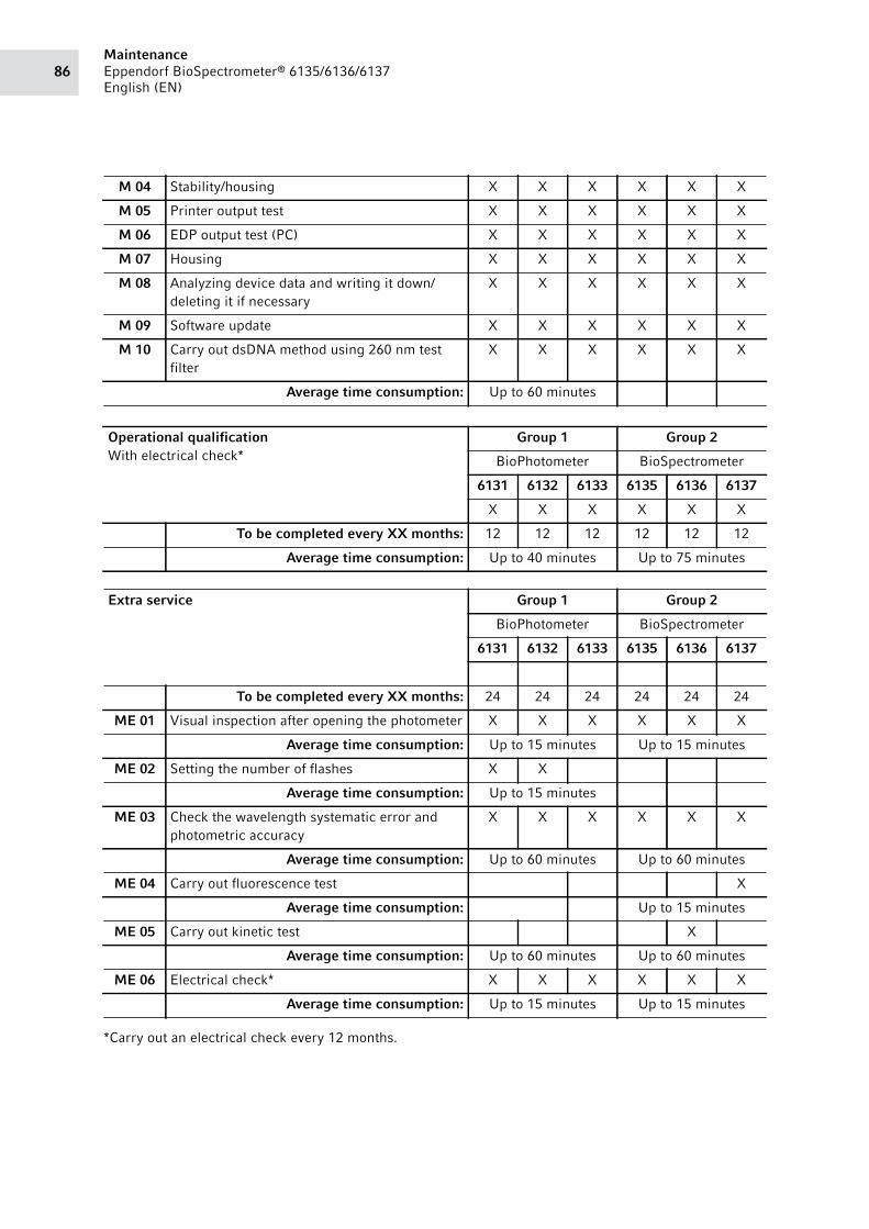
MaintenanceEppendorf BioSpectrometer® 6135/6136/6137
English (EN)86
*Carry out an electrical check every 12 months.
M 04 Stability/housing X X X X X X
M 05 Printer output test X X X X X X
M 06 EDP output test (PC) X X X X X X
M 07 Housing X X X X X X
M 08 Analyzing device data and writing it down/
deleting it if necessary
X X X X X X
M 09 Software update X X X X X X
M 10 Carry out dsDNA method using 260 nm test
filter
X X X X X X
Average time consumption: Up to 60 minutes
Operational qualificationWith electrical check*
Group 1 Group 2
BioPhotometer BioSpectrometer
6131 6132 6133 6135 6136 6137
X X X X X X
To be completed every XX months: 12 12 12 12 12 12
Average time consumption: Up to 40 minutes Up to 75 minutes
Extra service Group 1 Group 2
BioPhotometer BioSpectrometer
6131 6132 6133 6135 6136 6137
To be completed every XX months: 24 24 24 24 24 24
ME 01 Visual inspection after opening the photometer X X X X X X
Average time consumption: Up to 15 minutes Up to 15 minutes
ME 02 Setting the number of flashes X X
Average time consumption: Up to 15 minutes
ME 03 Check the wavelength systematic error and
photometric accuracy
X X X X X X
Average time consumption: Up to 60 minutes Up to 60 minutes
ME 04 Carry out fluorescence test X
Average time consumption: Up to 15 minutes
ME 05 Carry out kinetic test X
Average time consumption: Up to 60 minutes Up to 60 minutes
ME 06 Electrical check* X X X X X X
Average time consumption: Up to 15 minutes Up to 15 minutes

87Maintenance
Eppendorf BioSpectrometer® 6135/6136/6137
English (EN)
10.4 Description of service
Tab. 10-1: Standard service
M 01 Cleaning the device in accordance with its operating manualClean the BioSpectrometer as described in the corresponding operating manual and supplement
sheets.
M 02 Visual inspection of the displayIn particular, observe the following items:
• Defective pixels
• Background lighting
• Contrast
• Marginal sharpness
M 03 Key pad
Check the key pad using the corresponding service program and press all the keys.
• Keystroke
• Rebound
See: Service manual description 5.5.3.1 – "Key pad test" service function.
M 04 StabilityChecking the location surface:
• The surface must be level in order to guarantee the stability.
• The BioSpectrometer must be positioned on the working surface.
• All device feet must touch the working surface in order to prevent shifting which can be
caused by incident stray light.
M 05 Printer output testIf available, connect the DPU414 printer and test the printer output.
See: Service manual description 5.6.4.1 Customer service function "Spectrometer unit".
M 06 USB memory stick output testConnect the USB memory stick and test the output.
See: Service manual description 5.5.5.2 – "Log file" service function.
M 07 HousingClean the housing as described in the corresponding operating manual and supplement sheets.
Pay attention to damage that may compromise safety.
M 08 Analyzing device data and writing it down/deleting it if necessaryShow the following data along with the corresponding service program in the display:
• Check the date and time and set them, if necessary.
See: Service manual description 5.5.5.1 – "Device Information" service function.
M 09 Software updateTo use program enhancements, a software update is available free of charge within the scope of
service.
The USB interface to carry out a software update.
The latest software versions can be downloaded at the www.eppendorf-support.com website.
See SM description, Chapter 8: Software.
M 10 Carry out dsDNA method using 260 nm test filterThe result of the method must be within the limiting values of the UV/VIS test filter set of the
260 nm filter.
See user manual Chapter 6.1: Method selection.

MaintenanceEppendorf BioSpectrometer® 6135/6136/6137
English (EN)88
Tab. 10-2: Extra service features
ME 01 Visual inspection after opening the BioSpectrometerIn particular, observe the following items:
• Is there any liquid in the device or in the cuvette shaft?
• Clean or replace the affected parts.
See SM description, Chapter 6.1.2 – "Dismantling the housing".
ME 02 Carry out pixel wavelength assignmentSee SM description, Chapter 5.5.6.1 – "Optical adjustment" service function.
ME 03 Carry out SpectrometertestSee "SM description 5.6.4.1 "Spectrometer unit" customer service function.
ME 04 Carry out fluorescence testSee SM description, Chapter 5.6.4.4 – "Fluorescence unit" customer service function.
ME 05 Carry out kinetic testSee SM description, Chapter 5.6.4.2 – "Temperature unit" customer service function.
ME 06 Electrical checkSee "SOP description, Chapter 3.4 "Electrical check".

89Technical data
Eppendorf BioSpectrometer® 6135/6136/6137
English (EN)
11 Technical data11.1 Power supply
11.2 Ambient conditions
Do not expose to direct sunlight.
Power supply 100 V to 240 V ±10 %, 50 Hz to 60 Hz
Overvoltage category II
Degree of pollution 2
Power consumption Maximum power consumption according to name plate: 25 W
Approx. 15 W during operation
Approx. 5 W with the display dimmed
Power consumption Maximum power consumption according to name plate: 25 W
Approx. 15 W during operation
Approx. 5 W with the display dimmed and temperature control switched off
Power consumption Maximum power consumption according to name plate: 25 W
Approx. 15 W during operation
Approx. 5 W with the display dimmed
Permitted mains interruption Approx. 10 ms at 90 V
Approx. 20 ms at 230 V
Protection class I
Fuses T 2.5 A/250 V, 5 mm × 20 mm (2 pcs.)
Operation Ambient temperature: 15°C to 35°C
Rel. humidity: 25% to 70%
Air pressure: 86 kPa to 106 kPa
Air pressure Use up to an altitude of 2000 m above MSL

Technical dataEppendorf BioSpectrometer® 6135/6136/6137
English (EN)90
11.3 Weight/dimensions
11.4 Photometric properties
Weight 5 kg
Dimensions Width: 295 mm
Depth: 400 mm
Height:150 mm
Space required Width: 500 mm (with Eppendorf thermal printer: 750 mm)
Depth: 500 mm
Weight 5.3 kg
Dimensions Width: 295 mm
Depth: 400 mm
Height:150 mm
Space required Width: 500 mm (with Eppendorf thermal printer: 750 mm)
Depth: 500 mm
Weight 5.4 kg
Dimensions Width: 295 mm
Depth: 400 mm
Height:150 mm
Space required Width: 500 mm (with Eppendorf thermal printer: 750 mm)
Depth: 500 mm
Measuring principle Single beam absorption spectrophotometer with reference beam
Light source Xenon flash lamp
Monochromator Holographic aberration-corrected concave grating
Beam receiver CMOS photodiode array
Wavelengths 200 nm to 830 nm
Wavelength selection Method-dependent, freely selectable
Spectral bandwidth ≤ 4 nm
Smallest step size 1 nm
Systematic wavelength error ±1 nm
Random wavelength error ≤ 0.5 nm
Photometric measuring range 0 A to 3.0 A at 260 nm
Reading accuracy ΔA = 0.001
Random photometric error ≤ 0.002 at A = 0
≤ 0.005 (0.5 %) at A = 1
Systematic photometric error ±1 % at A = 1
Stray light component < 0.05 %

91Technical data
Eppendorf BioSpectrometer® 6135/6136/6137
English (EN)
11.5 Incubation
11.6 Further technical parameters
Adjustable temperature range 20°C to 42°C
Smallest step size 0.1°C
Systematic temperature error ±0.2 °C at 25 °C to 37 °C
Random temperature error ±0.15 °C at 25 °C to 37 °C
Cuvette material For measurements in the UV:
Quartz glass or UV transparent plastic (Eppendorf UVette, 220 nm to
1600 nm)
For measurements in the visible range:
Glass or plastic material
Cuvette shaft 12.5 mm × 12.5 mm, untempered
Cuvette shaft 12.5 mm × 12.5 mm, tempered
Overall cuvette height Min. 36 mm
Height of the light beam in the
cuvette
8.5 mm
Key pad 22 foil keys
6 foil keys as softkeys
Result output Absorbance, concentration, scan (absorbance wavelength spectrum)
Additional, method-dependent data (ratio, FOI, background
absorbances)
Fluorimetry: RFU, concentration
Display VGA TFT display 5.7”
Operator guidance language English, French, Spanish, Italian, German
Interfaces USB master for USB stick
USB slave for connecting to a PC
Interface for Eppendorf thermal printer: serial RS 232
Connected devices must meet the safety requirements specified in
IEC 60950-1.

Technical dataEppendorf BioSpectrometer® 6135/6136/6137
English (EN)92
11.7 Application parameters
Methods Preprogrammed and freely programmable methods for all measuring
and evaluation procedures:
• Absorbance measurements with one or more wavelengths, scans
• Fluorescence measurements at 520 nm or 560 nm
• Nucleic acids and proteins, OD600, dye methods (parallel
measurement of biomolecule and dye marking)
• Methods with evaluation via factor, standard and standard series
• Dual wavelength procedure with subtraction and division
evaluation
• Kinetic method: End point, two-point, linear regression
Method-dependent evaluation Absorbance, concentration via factor and standard.
RFU, concentration via standard
Concentration via standard series:
• Linear regression
• Nonlinear regression (2nd and 3rd degree polynoms)
• Spline evaluation
• Linear interpolation (point-to-point evaluation)
Absorbance calculations via subtraction and division
Additional data for nucleic acids: Ratios 260/280 and 260/230; molar
concentration, total yield
Additional data for dye methods: FOI (frequency of incorporation,
labeling density)
Scans: zoom, peak evaluation
Kinetics: Subsequent modification of the time window for the
regression evaluation
Method memory >100 method programs
Measured value memory and
calibration memory
Memory for >1 000 results with all data of the results evaluation and
standard evaluation, sample number, sample name, date and used
parameter set of the method program.
(The number of saved results depends on the number of saved
methods.)

93Ordering information
Eppendorf BioSpectrometer® 6135/6136/6137
English (EN)
12 Ordering informationAbb. 12-1: BioSpectrometer with closed housing
Fig. 12-1: BioSpectrometer with closed housing
4ghi
/ 2abc
3def1
jkl5 6
mno
pgrs7 8
tuv9wxyz
0µ %
method
function_
exit
delete
enterstandard blank sample
BioSpectrometer
kinetic
1-3 4-2

Ordering informationEppendorf BioSpectrometer® 6135/6136/6137
English (EN)94
Abb. 12-2: BioSpectrometer view from below
Fig. 12-2: BioSpectrometer view from below
BioSpectrometer
4-2 2-2 1-4 1-5

95Ordering information
Eppendorf BioSpectrometer® 6135/6136/6137
English (EN)
Abb. 12-3: BioSpectrometer upper part of housing
Fig. 12-3: BioSpectrometer upper part of housing
BioSpectrometer
1-2

Ordering informationEppendorf BioSpectrometer® 6135/6136/6137
English (EN)96
Abb. 12-4: BioSpectrometer with dismantled housing
Fig. 12-4: BioSpectrometer with dismantled housing
3-2
3-7
3-5
3-3
3-1
2-4
2-1
1-1
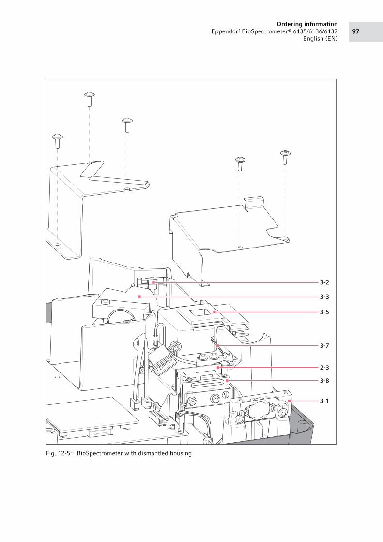
97Ordering information
Eppendorf BioSpectrometer® 6135/6136/6137
English (EN)
Abb. 12-5: BioSpectrometer with dismantled housing
Fig. 12-5: BioSpectrometer with dismantled housing
3-2
3-3
3-5
3-7
2-3
3-1
3-8

Ordering informationEppendorf BioSpectrometer® 6135/6136/6137
English (EN)98
Abb. 12-6: BioSpectrometer keypad
Fig. 12-6: BioSpectrometer keypad
Abb. 12-7: BioSpectrometer fluorescence cuvette holder
Fig. 12-7: BioSpectrometer fluorescence cuvette holder
1-3
3-5

99Ordering information
Eppendorf BioSpectrometer® 6135/6136/6137
English (EN)
Abb. 12-8: BioSpectrometer kinetic cuvette holder
Fig. 12-8: BioSpectrometer kinetic cuvette holder
Abb. 12-9: BioSpectrometer basic cuvette holder
Fig. 12-9: BioSpectrometer basic cuvette holder
3-5
3-5

Ordering informationEppendorf BioSpectrometer® 6135/6136/6137
English (EN)100
Abb. 12-10: BioSpectrometer fiber optic cable
Fig. 12-10: BioSpectrometer fiber optic cable
Abb. 12-11: Cuvette shaft adjustment tool
Fig. 12-11: Cuvette shaft adjustment tool
3-7
5-5

101Ordering information
Eppendorf BioSpectrometer® 6135/6136/6137
English (EN)
Abb. 12-12: Lamp adjustment tool
Fig. 12-12: Lamp adjustment tool
12.1 Spare parts
12.1.1 Housing
Fig. Item Order no. (International)
Description
— 1-1 6135 852.005 Mains input module12-3 1-2 6135 854.008 Display cpl., incl. Cable
Keypad12-1 1-3 6135 861.004 6135 basic
12-1 1-3 6136 861.008 6136 kinetic
12-1 1-3 6137 861.001 6137 fluorescence
Spherical foot12-2 1-4 5355 863.001 set of 4
Spherical support12-2 1-5 5353 861.001 dark, set of 4
- 1-6 6135 873.002 Upper part of housing without keypad
5-1

Ordering informationEppendorf BioSpectrometer® 6135/6136/6137
English (EN)102
12.1.2 Electrical/electronic equipment
12.1.3 Light path
12.1.4 Accessories
Fig. Item Order no. (International)
Description
12-4 2-1 6135 853.001 Switched power supply unitFan
12-2 2-2 6136 852.009 DC
12-5 2-3 6135 855.004 PCB sensor12-4 2-4 6136 859.003 PCB BioSpectrometer
Fig. Item Order no. (International)
Description
12-4 3-1 6135 865.107 Diffraction grating with holder, incl. mirror12-4 3-2 6135 866.103 Mirrow12-4 3-3 6135 864.003 Lampholder cpl., pre-adjusted
incl. reference diode
Cuvette shaft insulation— 3-4 6135 869.005 basic / kinetic
Cuvette holder12-8 3-5 6135 851.009 basic
12-7 3-5 6136 851.002 kinetic
12-12 3-5 6137 851.006 fluorescence
12-9 3-7 6135 856.000 Fiber-optic cable12-5 3-8 6135 857.104 Photo diode array, incl. mirror
Fig. Item Order no. (International)
Description
— 4-1 6135 867.002 PackingCuvette shaft cover
12-1 4-2 6135 872.006 6135 basic / kinetic
12-1 4-2 6137 872.003 6137 fluorescence

103Ordering information
Eppendorf BioSpectrometer® 6135/6136/6137
English (EN)
12.1.5 Auxiliary aids
Fig. Item Order no. (International)
Description
Adjustment tool12-10 5-1 6135 868.009 lamp
12-11 5-5 6135 871.000 cuvette shaft
— 5-2 6135 931.002 Test filter kitTest filter
— 5-3 6137 935.005 fluorescence
— 5-4 5075 851.563 RS 232 DummyCertification test filter set
— 5-6 6137 935.102 fluorescence
— 5-7 6135 931.100 Certification test filter kitTemperature sensor
— 5-8 6135 870.003 for BioSpectrometer kinetic
Add the holmium filter and didymium filter material safety data sheets to the test filter kit
(art. no. 6135 931.002). The material safety data sheets can be found in the product area of the
http://www.eppendorf-support.com website.
Always use the test filter kit (art. no. 6135 931.002) in the original packaging.

Ordering informationEppendorf BioSpectrometer® 6135/6136/6137
English (EN)104

13 Technical information
Evaluate your manual
Give us your feedback.
www.eppendorf.com/manualfeedback
Your local distributor: www.eppendorf.com/contactEppendorf AG · 22331 Hamburg · Germany
[email protected] · www.eppendorf.com


