EQMF AIR COOLED LIQUID CHILLERS WITH FREE-COOLING SYSTEM FOR OUTDOOR INSTALLATION Air cooled liquid Chillers with Free Cooling System TECHNICAL CATALOGUE Models:60.1│60.2│70.1│70.2│90.1│90.2│120.1│120.2│135.1│ 150.1│190.2│200.1│200.2│240.2│270.2│300.2│ Cooling capacities: 19,9 to 258 KW 03.16 ref. 207621 Rev.100
Transcript
EQMF
AIR COOLED LIQUID CHILLERS WITH FREE-COOLING SYSTEM FOR OUTDOOR
INSTALLATION
INVERTER
Air cooled liquid Chillers with Free Cooling System
Thank you for trusting in Hitecsa Products. Our company has been offering the market an extended range of specialized units for
air conditioning and cooling installations for over 30 years. Our approach is based on efficiency, adaptability, usability and practical
solutions. This has been the hallmark of our product catalogue.
The versatility of our factory allows us to contribute solutions, almost tailored to each project’s specifications, in search of a
solution to every problem that arises in design and implementation of air conditioning installations.
From all of us at Hiplus Aire Acondicionado, once again, thank you very much
GENERAL CHARACTERISTICS............................................................................................................................... 4
EQEF SERIES .......................................................................................................................................................... 4
OPERATING AREA “A” ..................................................................................................................................................... 5
OPERATING AREA “B” ..................................................................................................................................................... 5
MAIN COMPONENTS ............................................................................................................................................... 7
FAN SECTIONS ................................................................................................................................................................... 7
CONTROL SYSTEM ............................................................................................................................................................ 7
OTHER ACCESSORIES ..................................................................................................................................................... 8
GENERAL CHARACTERISTICS Packaged air cooled liquid chillers with free-cooling section, for chilled water production. The machines are made with weather resistant materials and suitable for outdoor installation. Framework with sections of thick steel for high resistance to the greatest stress during handling and transport. Machines supply fully assembled with refrigerant charge and control systems. The installation requires electrical and hydraulic connections only allowing high costs and time reduction. Final assembly on all machines before shipment including running test, reading and monitoring of operating parameters, alarms simulation and visual check. Design, assembly and test as per the Company Quality Assurance program in full compliance with ISO 9001:2008. Environmental Management System Certification according to ISO 14001:2004. The machines are in full compliance with European Directive 2006/42EC, 2006/95EC, 2004/108EC, 97/23EC and subsequent amendments.
EQMF SERIES Machines equipped with single condensing coil in vertical position, scroll compressors, axial fans, welded plate heat exchangers and free-cooling section. Horizontal air suction and vertical discharge.
EQMF MODELS EQMF 70 . 2
2 Number of cooling circuits 70 Cooling capacity in KW @ standard conditions
AIR COOLED WATER CHILLERS WITH FREE-
COOLING SYSTEM
EQMF
03.16 Ref.207621 Rev.100
5
OPERATING LIMITS
Mechanical Cooling – Production of chilled water
Operating limits diagram for chilled water production according to the ambient temperature and chilled water outlet
temperature.
OPERATING AREA “A” Area where the machine’s cooling capacity can be calculated with the selection software.
OPERATING AREA “B”
Area where the machine’s cooling capacity must be calculated by our commercial support department. Operating temperatures are influenced by a list of variables, such as: - Operating conditions. - Thermal load. - Active power steps. - Cleanliness of the finned pack heat exchanger. - Micropossesor control configuration.
AIR COOLED WATER CHILLERS WITH FREE-
COOLING SYSTEM
EQMF
03.16 Ref.207621 Rev.100
6
Mechanical Cooling – Production of chilled water
Working limits diagram for chilled water production in Free-Cooling mode, according to the ambient temperature and chilled water inlet temperature.
PARTIAL HEAT RECOVERY Working limits for hot water production from partial heat reclaim system. The system is not regulated and the heating capacity which is supplied depends on the machine working conditions. 40÷75 °C hot water outlet temperature range 5÷15 °C Δt range between water inlet/outlet.
ANTIFREEZE MIXTURES Antifreeze mixtures have to be used when the machine working conditions foresee the chilled outlet liquid temperature below 5 °C.
PROPYLENE GLYCOL
ETHYLENE GLYCOL
STORAGE TEMPERATURE If the unit is not installed immediately after reception and is to be stored for an extended period of time, please, make sure that storage temperatures range between -30 and 50ºC and the unit is not subject to condensation or direct sunlight.
Chilled water outlet temp.
ºC 4 2 1 -2 -4 -6 -9 -12
Percentage of mix in weight
% 5 10 15 20 25 30 35 40
Chilled water outlet temp.
ºC 4 2 0 -4 -7 -9 -10 -12
Percentage of mix in weight
% 5 10 15 20 25 30 35 38
Attention:
These values refer to the machine’s operating temperature. The use of antifreeze mixtures may result in a decrease in the unit’s performance. Please, use the selection program to obtain the effective performance.
AIR COOLED WATER CHILLERS WITH FREE-
COOLING SYSTEM
EQMF
03.16 Ref.207621 Rev.100
7
MAIN COMPONENTS
FRAMEWORK Base, self-supporting frame and panels in steel sheet with protective surface treatments in compliance with UNI ISO 9227/ ASTMB117 and ISO 7253, and painted with epoxy powders. Colour: Ral 9002
with spiral profile optimized for R410A refrigerant. - ON / OFF capacity control (0 / 100% each
compressor). - 2-pole 3-phase electric motor with direct on line
starting. - Phase sequence electronic relay. - Crankcase heater. - Electric motor thermal protection via internal
winding temperature sensors. - Rubber supports.
EVAPORATOR - Copper brazed plate type with cover plates, plates
and connections in AISI 316 stainless steel: With single refrigerant circuit for "1" version machines. With double refrigerant circuit for "2" version machines.
- Anticondensate insulation made of polyurethane. - Temperature sensors on water inlet and outlet. - Water flow safety switch. - Antifreeze heater.
CONDENSING COIL - Heat exchanger coil with internally corrugated
copper tubes and high efficiency aluminium fins, specifically developed to provide high heat transfer and lower pressure drops. The combination of two factors, special tubes and fins, allow to optimally combine the following aspects : Maximum capacity relative to the size of the exchanger. Minimum charge of refrigerant. Reduction of the air flow required for the heat exchange.
- Sub-cooling circuit to allow a significant increase in cooling capacity.
- Frame in galvanized steel.
FREE-COOLING COIL - Heat exchanger coil with internally corrugated
copper tubes and high efficiency aluminium fins, specifically developed to provide high heat transfer and lower pressure drops. The combination of two factors, special tubes and fins, allow to optimally combine the following aspects : Maximum capacity relative to the size of the exchanger. Minimum charge of refrigerant. Reduction of the air flow required for the heat exchange.
- Frame in galvanized steel. - Motorized valves for free-cooling water circuit
control. - Temperature sensor on ambient air,
FAN SECTIONS - Thermostatic expansion valve. - Electronic expansion valve. The valve allows high - performance and system efficiency thanks to a
timely and accurate response to changes in
temperature and pressure. The electronic expansion valve excludes the installation of the electromagnetic valve on liquid line.
- Sight glass - Liquid receiver.
COOLING CIRCUIT Components for each refrigerant circuit: - Electronic expansion valve. The valve allows high
performance and system efficiency thanks to a timely and accurate response to changes in temperature and pressure.
- Thermostatic expansion valve. - Sight glass. - Liquid receiver. - Electromagnetic valve no liquid line. The
electromagnetic valve is not installed when the electronic expansion valve is present.
- Filter dryer on liquid line. - Service valves on liquid line and gas discharge. - Safety valve on low pressure side. - Safety valve on high pressure side. - Pressure transducers with indication, control and
protection functions, on low and high refrigerant pressure.
- High pressure safety switch with manual reset. - Refrigerant circuit with copper tubing with
anticondensate insulation of the suction line. - Plastic capillary hoses for pressure sensors
connection. - R410A refrigerant charge.
ELECTRICAL PANEL In accordance with EN60204-1 norms, suitable for outdoor installation, complete with: - Main switch with door lock safety. - Magnetothermic switch or fuses for each
compressor. - Magnetothermic switches for fans or water pumps
(if scheduled). - Contactors for each load. - Transformer for auxiliary circuit and microprocessor
supply. - Panel with machine controls. - Power supply 400/3/50.
CONTROL SYSTEM MP.COM microprocessor system with graphic display for control and monitor of operating and alarms status. The system includes : - Voltage free contact slot for remote general alarm. - Main components hour-meter. - Non-volatile "Flash" memory for data storage. - Menu with password protection. - LAN connection.
HYDRAULIC CONNECTIONS - The heat exchangers’ threaded hydraulic
connections are available up to a diameter of 3" included, and correspond to ISO 228/1 – G M.
- The pipes’ threaded hydraulic connections are available up to a diameter of 3 " included, and correspond to ISO 7/1 – R.
- The hydraulic connections with flange (FL) are not supplied with counter flange.
- The hydraulic connections with grooved end are not supplied with flexible joint (optional accessory).
AIR COOLED WATER CHILLERS WITH FREE-
COOLING SYSTEM
EQMF
03.16 Ref.207621 Rev.100
8
ACCESSORIES The description of these additional components can be found in Chapter OPTIONAL ACCESSORIES.
- Pumping group with 1 pump. - Pumping group with 2 pumps. - Water tank - LNO KIT for noise emission reductions. - ELN KIT for extreme noise emission reductions. - Partial heat recovery system. - Silencing plenum on condenser air discharge.
OTHER ACCESSORIES - BRINE kit for chilled water production up to -12ºC WARNING With BRINE Kit it is mandatory to use antifreeze mixture. Refer to the paragraph ANTIFREEZE SOLUTION. Using antifreeze mixtures results in a decrease in the unit’s performance
(PLEASE, CONSULT OUR COMMERCIAL DEPARTMENT)
- Hydraulic connections of the evaporator: Flexible joint with adapter pipe (solder type). Flexible joint with adapter for flange connection (FL). The counter- flange is not supplied.
- Condensing coil protection net. - Condensing coil in Cu/Al coated execution. - Condensing coil in special execution (please contact our Commercial Dept.). - Spring antivibrating supports - not installed. - Rubber supports - not installed. - Heating system for electrical panel (suggested for operating condition of the machines with negative
ambient temperature). - Expansion valve energy reserve module to allow the closure of the valve in the event of lack of power
supply. - Water flow switch for water flow control. - Power factor capacitor for motor compressor - cos φ 0,9. - Ambient temperature sensor. The ambient temperature sensor requires the installation od “Additional
module” and “Driver for additional module” optional accessories. - MP.COM microprocessor control accessories:
- Remote terminal. - Clock card for alarms, date and time displaying and storing. - RCcom serial port, - MBUS/JBUS. - LON serial port. - BACnet pour Ethernet – SNMP – TCP/IP serial ports. - BACnet pour MS/TP serial ports. - Serial port for GSM modem. - Date logger for registering and storing alarm signals. - Additional module with the following inputs / outputs :
INPUTS : External alarm 1. External alarm 2. Line current indication. Line voltage indication / Compensation. Ambient air temperature. OUTPUTS : External alarm 1. External alarm 2. General alarm 2. General alarm 3.
- Driver for the additional module. Attention: It is compulsory to install a water filter on evaporator water inlet (not supplied with the machine). We reserve the right to approve any of the possible combinations of accessories to be installed.
1. Intake/Outlet chilled water temperature 12/7 °C; glycol ethylene solution 20%; ambient air temperature 35 °C 2. Intake/Outlet chilled water temperature 12/7 °C; glycol ethylene solution 20%; ambient air temperature 3 °C 3. Average sound pressure levels [Lpm] measured 1m away, in accordance to ISO EN 3744.
4. Acoustic power levels [Lw] in accordance to ISO EN 9614 – 2.
1. Intake/Outlet chilled water temperature 12/7 °C; glycol ethylene solution 20%; ambient air temperature 35 °C 2. Intake/Outlet chilled water temperature 12/7 °C; glycol ethylene solution 20%; ambient air temperature 3 °C 3. Average sound pressure levels [Lpm] measured 1m away, in accordance to ISO EN 3744. 4. Acoustic power levels [Lw] in accordance to ISO EN 9614 – 2.
AIR COOLED WATER CHILLERS WITH FREE-
COOLING SYSTEM
EQMF
03.16 Ref.207621 Rev.100
11
MODEL 180.2 197.1 197.2 230.1 240.2 270.2
CAPACITIES
Cooling capacity (1) KW 198 215 212 242 270 299
Compressors power input KW 68,4 79,9 76,9 97,2 94,1 112
Compressors operating current A 116 135 129 163 162 189
Water temperature (int) ºC 15 15 15 15 15 15
Water temperature (ext) ºC 10 10 10 10 10 10
Evaporator water flow m3/h 36,4 39,7 39,1 44,7 49,8 54,5
Evaporator pressure drop KPa 106 147 138 168 159 171
FREE COOLING
Cooling capacity (2) KW 141 151 150 159 171 197
REFRIGERANT
Type R-410A
Charge Kg 65,8 93,1 102,2 35,6 127 126,6
Gas circuits 2 1 2 1 2 2
GWP 2088 2088 2088 2088 2088 2088
COMPRESSOR
Type SCROLL
Number 2 2 2 2 2 2
Max. absorbed current A 147,4 164 164 196,2 194 227,8
Starting current A 459,4 476 476 440,8 417,5 472,4
Acoustic power (4) dB(A) 93,3 93,7 93,7 94,7 93,4 93,4
DIMENSIONS AND WEIGHT
Length mm 4950 4950 4950 4950 4950 4950
Width mm 1500 1500 1500 1500 1500 1500
Height mm 2090 2090 2090 2090 2090 2090
Net weight Kg 22101 2220 2230 2370 2510 2510
1. Intake/Outlet chilled water temperature 12/7 °C; glycol ethylene solution 20%; ambient air temperature 35 °C
2. Intake/Outlet chilled water temperature 12/7 °C; glycol ethylene solution 20%; ambient air temperature 3 °C 3. Average sound pressure levels [Lpm] measured 1m away, in accordance to ISO EN 3744. 4. Acoustic power levels [Lw] in accordance to ISO EN 9614 – 2.
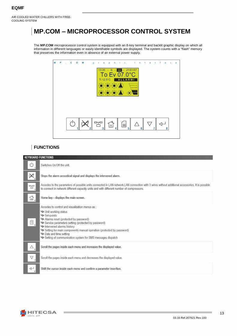
MP.COM – MICROPROCESSOR CONTROL SYSTEM The MP.COM microprocessor control system is equipped with an 8-key terminal and backlit graphic display on which all information in different languages or easily identifiable symbols are displayed. The system counts with a "flash" memory
that preserves the information even in absence of an external power supply.
To obtain more information, please refer to the software catalogue of the unit.
AIR COOLED WATER CHILLERS WITH FREE-
COOLING SYSTEM
EQMF
03.16 Ref.207621 Rev.100
15
OPTIONAL ACCESSORIES – PUMPING GROUP
Factory assembled pumping group. The system doesn't modify the machine dimensions. In the chillers technical data tables are showed the pumping group type for each machine. The system includes: SINGLE PUMP VERSION .../1 Pumping group with one in-line pump:
Control and working electric equipment built in the water chiller electric board and directly managed by the microprocessor control.
Pump with 2 poles electric motor (PPF MAX series).
Insulated piping.
Expansion tank.
Safety valve.
Safety flow switch.
Pressure gauge on water suction and discharge
Valve for water filling/discharge. TWO PUMPS VERSION .../2 Pumping group with twin head in-line pumps.
Control and working electric equipment built in the water chiller electric board and directly managed by the microprocessor control.
Pump with 2 poles electric motor (PPF MAX model).
Insulated piping.
Expansion tank.
Safety valve.
Safety flow switch.
Pressure gauge on water suction and discharge
Valve for water filling/discharge.
One pump is working and the other is in stand-by. Automatic changeover in case of failure.
AIR COOLED WATER CHILLERS WITH FREE-
COOLING SYSTEM
EQMF
03.16 Ref.207621 Rev.100
16
TECHNICAL DATA
EQEF
SINGLE PUMP MODEL TWIN PUMP MODEL
1/1 2/1 3/1 4/1 5/1 3/2 4/2 5/2
WATER FLOW
Min water flow m3/h 2 8 5 5 10 5 30 60
Max water flow m3/h 14 28 35 35 60 35 50 100
DISCHARGE HEAD
At min water flow KPa 190 180 213 213 261 213 245 255
At max water flow KPa 85 125 193 193 255 175 1785 180
WATER PUMPS
Absorbed power KW 1,1 1,5 3 3 5,5 3 4 7,5
Absorbed current A 2,7 3,5 6,1 6,1 10,3 6,1 7.8 13,8
POWER SUPPLY
Voltage V/ph/Hz 400 / III / 50
WEIGHT
Empty weight Kg 32,5 34,5 68 68 84 116 130 182
(1) The given value is referred to the working pump only. (2) Add the weight values to the weight of the chiller.
Warning: Noise generated by the pumps does not increase the unit’s overall acoustic levels.
AIR COOLED WATER CHILLERS WITH FREE-
COOLING SYSTEM
EQMF
03.16 Ref.207621 Rev.100
17
PUMP PERFORMANCE – MODELS WITH SINGLE PUMP
The graph is referred to performances values of the pump.
To obtain the pressure available for the plant, deduct the pressure drop of the relative heat exchanger as
indicated in unit technical data.
AIR COOLED WATER CHILLERS WITH FREE-
COOLING SYSTEM
EQMF
03.16 Ref.207621 Rev.100
18
PUMP PERFORMANCE – MODELS WITH TWIN HEAD PUMP
The graph is referred to performances values of the pump.
To obtain the pressure available for the plant, deduct the pressure drop of the relative heat exchanger as
indicated in unit technical data.
AIR COOLED WATER CHILLERS WITH FREE-
COOLING SYSTEM
EQMF
03.16 Ref.207621 Rev.100
19
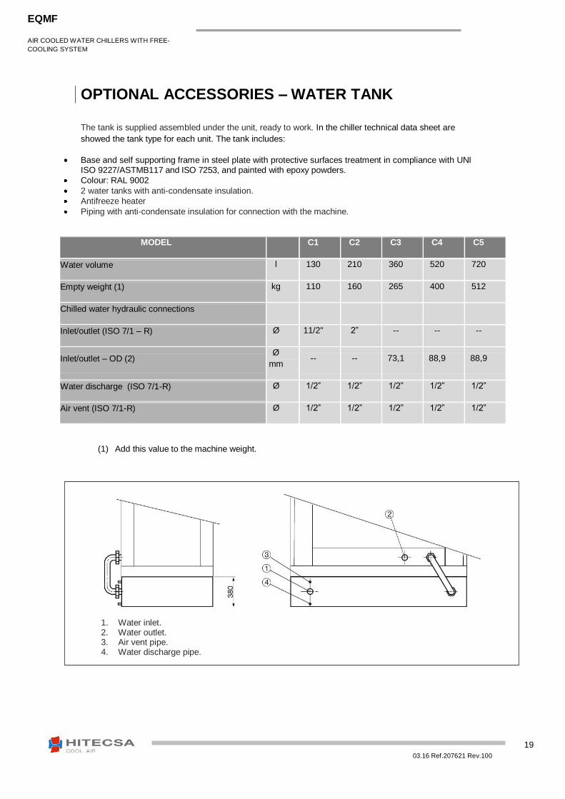
OPTIONAL ACCESSORIES – WATER TANK
The tank is supplied assembled under the unit, ready to work. In the chiller technical data sheet are
showed the tank type for each unit. The tank includes:
Base and self supporting frame in steel plate with protective surfaces treatment in compliance with UNI ISO 9227/ASTMB117 and ISO 7253, and painted with epoxy powders.
Colour: RAL 9002
2 water tanks with anti-condensate insulation.
Antifreeze heater
Piping with anti-condensate insulation for connection with the machine.
MODEL C1 C2 C3 C4 C5
Water volume l 130 210 360 520 720
Empty weight (1) kg 110 160 265 400 512
Chilled water hydraulic connections
Inlet/outlet (ISO 7/1 – R) Ø 11/2" 2” -- -- --
Inlet/outlet – OD (2) Ø
mm -- -- 73,1 88,9 88,9
Water discharge (ISO 7/1-R) Ø 1/2” 1/2” 1/2” 1/2” 1/2”
Air vent (ISO 7/1-R) Ø 1/2” 1/2” 1/2” 1/2” 1/2”
(1) Add this value to the machine weight.
1. Water inlet. 2. Water outlet. 3. Air vent pipe. 4. Water discharge pipe.
AIR COOLED WATER CHILLERS WITH FREE-
COOLING SYSTEM
EQMF
03.16 Ref.207621 Rev.100
20
OPTIONAL ACCESSORIES – LNO KIT
This optional is available as accessory to obtain a machine noise reduction. The versions equipped with LNO KIT have the following characteristics : - Set of the working parameters. - Technical compartment and panels insulated with polyurethane for sound proofing. - Cap with sound-absorbing material on each compressor. The LNO KIT allows 3 different types of set : LNO KIT 100%
No air flow reduction. Noise reduction is obtained through a different working set of the microprocessor control and an acoustic insulation of the noise source. LNO KIT 85%
Noise reduction is obtained through a different working set of the microprocessor control, an acoustic insulation of the noise source and a reduction of the condenser coil air flow at 85% of the nominal value. Consider that a condenser coil air flow reduction induces a minor cooling capacity of the machine
and a major energy consumption of the compressor.
Warning : To obtain the effective working conditions of cooling capacity and noise reduction for unit equipped with LNO KIT, please refer to the selection program.
ACOUSTIC DATA
100% LNO KIT
MODELS 58.1 58.2 62.1 65.1 76.1 76.2 Total air flow m
3/h 210000 210000 22000 23000 25750 25750
Power input kW 1,5 1,5 1,7 2 2,5 2,5
Sound power level [Lw] (1)
dB(A) 87,9 87,9 91,5 87,9 87 87
AVERAGE SOUND PRESSURE LEVEL [Lpm] at 1 m (2) dB(A) 70 70 73,6 70 69,2 69,2
[Lpm] at 5 m (2) dB(A) 61,2 61,2 64,7 61,2 60,3 60,3
[Lpm] at 10 m (2) dB(A) 56,1 56,1 59,7 56,1 55,2 55,2
MODELS 98.1 98.2 124.1 124.2 158.1 158.2 Total air flow m
3/h 35000 35000 42000 42000 46800 46800
Power input kW 2,7 2,7 4,7 4,7 7,1 7,1
Sound power level [Lw] (1)
dB(A) 86,2 86,2 90,6 90,6 92,8 92,8
AVERAGE SOUND PRESSURE LEVEL [Lpm] at 1 m (2) dB(A) 67,6 67,6 72 72 74,2 74,2
[Lpm] at 5 m (2) dB(A) 59,1 59,1 63,5 63,5 65,8 65,8
[Lpm] at 10 m (2) dB(A) 54,2 54,2 58,6 58,6 60,8 60,8
AIR COOLED WATER CHILLERS WITH FREE-
COOLING SYSTEM
EQMF
03.16 Ref.207621 Rev.100
21
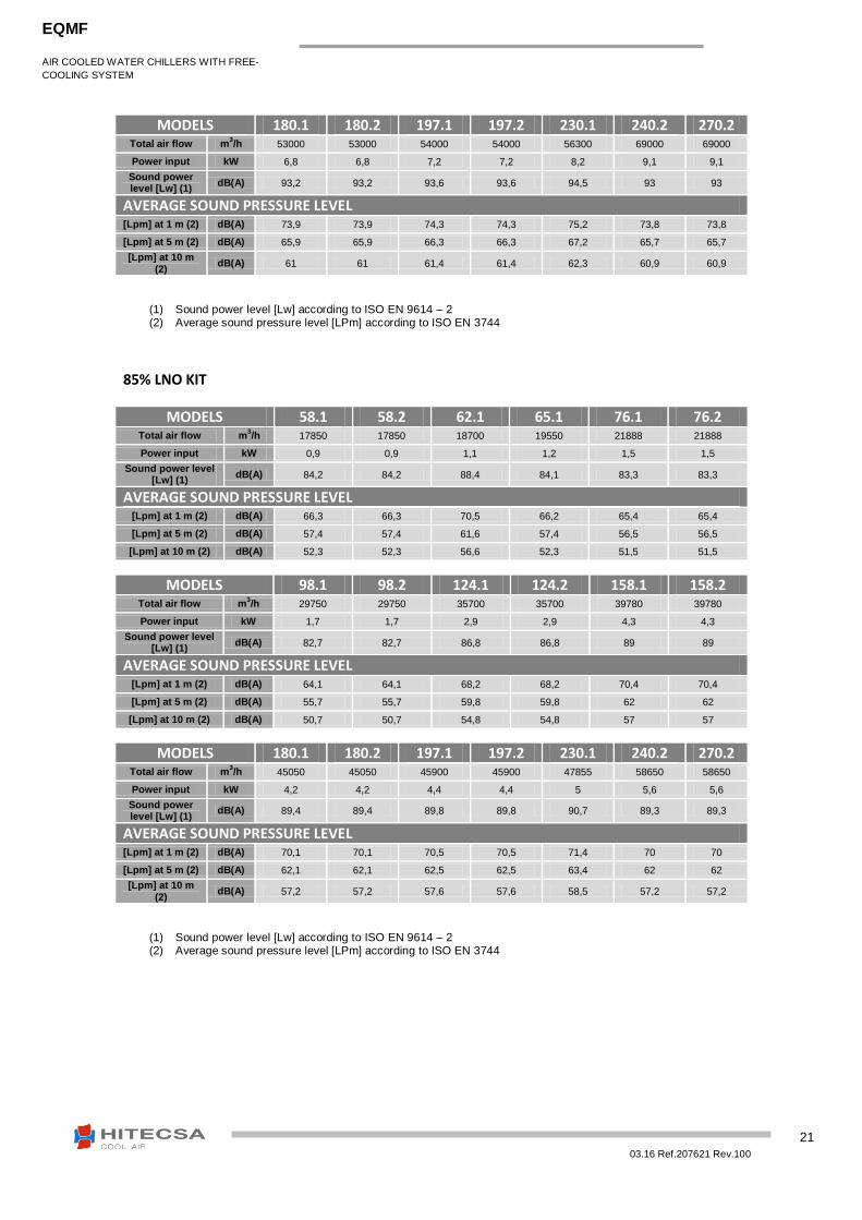
MODELS 180.1 180.2 197.1 197.2 230.1 240.2 270.2 Total air flow m
3/h 53000 53000 54000 54000 56300 69000 69000
Power input kW 6,8 6,8 7,2 7,2 8,2 9,1 9,1
Sound power level [Lw] (1)
dB(A) 93,2 93,2 93,6 93,6 94,5 93 93
AVERAGE SOUND PRESSURE LEVEL [Lpm] at 1 m (2) dB(A) 73,9 73,9 74,3 74,3 75,2 73,8 73,8
[Lpm] at 5 m (2) dB(A) 65,9 65,9 66,3 66,3 67,2 65,7 65,7
[Lpm] at 10 m (2)
dB(A) 61 61 61,4 61,4 62,3 60,9 60,9
(1) Sound power level [Lw] according to ISO EN 9614 – 2 (2) Average sound pressure level [LPm] according to ISO EN 3744
85% LNO KIT
MODELS 58.1 58.2 62.1 65.1 76.1 76.2 Total air flow m
3/h 17850 17850 18700 19550 21888 21888
Power input kW 0,9 0,9 1,1 1,2 1,5 1,5
Sound power level [Lw] (1)
dB(A) 84,2 84,2 88,4 84,1 83,3 83,3
AVERAGE SOUND PRESSURE LEVEL [Lpm] at 1 m (2) dB(A) 66,3 66,3 70,5 66,2 65,4 65,4
[Lpm] at 5 m (2) dB(A) 57,4 57,4 61,6 57,4 56,5 56,5
[Lpm] at 10 m (2) dB(A) 52,3 52,3 56,6 52,3 51,5 51,5
MODELS 98.1 98.2 124.1 124.2 158.1 158.2 Total air flow m
3/h 29750 29750 35700 35700 39780 39780
Power input kW 1,7 1,7 2,9 2,9 4,3 4,3
Sound power level [Lw] (1)
dB(A) 82,7 82,7 86,8 86,8 89 89
AVERAGE SOUND PRESSURE LEVEL [Lpm] at 1 m (2) dB(A) 64,1 64,1 68,2 68,2 70,4 70,4
[Lpm] at 5 m (2) dB(A) 55,7 55,7 59,8 59,8 62 62
[Lpm] at 10 m (2) dB(A) 50,7 50,7 54,8 54,8 57 57
MODELS 180.1 180.2 197.1 197.2 230.1 240.2 270.2 Total air flow m
3/h 45050 45050 45900 45900 47855 58650 58650
Power input kW 4,2 4,2 4,4 4,4 5 5,6 5,6
Sound power level [Lw] (1)
dB(A) 89,4 89,4 89,8 89,8 90,7 89,3 89,3
AVERAGE SOUND PRESSURE LEVEL [Lpm] at 1 m (2) dB(A) 70,1 70,1 70,5 70,5 71,4 70 70
[Lpm] at 5 m (2) dB(A) 62,1 62,1 62,5 62,5 63,4 62 62
[Lpm] at 10 m (2)
dB(A) 57,2 57,2 57,6 57,6 58,5 57,2 57,2
(1) Sound power level [Lw] according to ISO EN 9614 – 2 (2) Average sound pressure level [LPm] according to ISO EN 3744
AIR COOLED WATER CHILLERS WITH FREE-
COOLING SYSTEM
EQMF
03.16 Ref.207621 Rev.100
22
OPTIONAL ACCESSORIES – ELN KIT
This optional is available as accessory to obtain an extreme machine noise reduction.
The versions equipped with ELN kit have the following characteristics:
- Set of the working parameters. - Machine frame and panels insulated with soundproofing material. - Soundproof cap on each compressor. Consider that a condenser coil air flow reduction induces a minor cooling capacity of the machine and a major energy
consumption of the compressor.
Warning : To obtain the effective working conditions of cooling capacity and noise reduction for unit equipped
with ELN KIT, please refer to the selection program.
ACOUSTIC DATA
MODELS 58.1 58.2 62.1 65.1 76.1 76.2 Total air flow m
3/h 14700 14700 15400 16100 18025 18025
Power input kW 0,5 0,5 0,6 0,7 0,8 0,8
Sound power level [Lw] (1)
dB(A) 79,9 79,9 85,6 79,8 79,1 79,1
AVERAGE SOUND PRESSURE LEVEL [Lpm] at 1 m (2) dB(A) 62 62 67,7 61,9 61,2 61,2
[Lpm] at 5 m (2) dB(A) 53,2 53,2 58,9 53 52,3 52,3
[Lpm] at 10 m (2) dB(A) 48,1 48,1 53,8 48 47,2 47,2
MODELS 98.1 98.2 124.1 124.2 158.1 158.2 Total air flow m
3/h 24500 24500 29400 29400 32760 32760
Power input kW 0,9 0,9 1,6 1,6 2,4 2,4
Sound power level [Lw] (1)
dB(A) 79,2 79,2 82,7 82,7 84,6 84,6
AVERAGE SOUND PRESSURE LEVEL [Lpm] at 1 m (2) dB(A) 60,6 60,6 64,1 64,1 66 66
[Lpm] at 5 m (2) dB(A) 52,2 52,2 55,6 55,6 57,6 57,6
[Lpm] at 10 m (2) dB(A) 47,2 47,2 50,7 50,7 52,6 52,6
MODELS 180.1 180.2 197.1 197.2 230.1 240.2 270.2 Total air flow m
3/h 37100 37100 37800 37800 39410 48300 48300
Power input kW 2,3 2,3 2,5 2,5 2,8 3,1 3,1
Sound power level [Lw] (1)
dB(A) 85 85 85,4 85,4 86,3 85,2 85,2
AVERAGE SOUND PRESSURE LEVEL [Lpm] at 1 m (2) dB(A) 65,7 65,7 66,1 66,1 67,1 65,9 65,9
[Lpm] at 5 m (2) dB(A) 57,7 57,7 58,1 58,1 58,1 57,9 57,9
[Lpm] at 10 m (2)
dB(A) 52,8 52,8 53,2 53,2 53,2 53 53
AIR COOLED WATER CHILLERS WITH FREE-
COOLING SYSTEM
EQMF
03.16 Ref.207621 Rev.100
23
OPTIONAL ACCESSORIES – PARTIAL HEAT RECOVERY SYSTEM
The partial heat recovery exchangers are installed on every refrigerant circuit of the machine before the main
condenser. The system is not regulated and the control is ON-OFF type. The heat recovery system’s operation is
subject to the supply demand of cooling capacity.
The system includes:
- Copper brazed plate type heat exchanger with cover plates, plates and connections in AISI 316 stainless steel. - Anticondensate insulation made of polyurethane. - Hydraulic piping.
The heating capacity which is supplied depends on the kind of refrigerant gas which is used and on working
temperatures. The heat exchangers can produce hot water up to the maximum temperature of 70÷75 °C and according
to the working conditions of the unit.
AIR COOLED WATER CHILLERS WITH FREE-
COOLING SYSTEM
EQMF
03.16 Ref.207621 Rev.100
24
OPTIONAL ACCESSORIES – SILENCING PLENUM ON CONDENSER AIR
The plenum is supplied as separate accessory for installation on site.
The system includes:
Aluminium profile frame jointed with reinforced PVC corners.
Panelling in steel plate with protective surface treatment in compliance with UNI ISO 9227/ASTMB117 and
ISO 7253, and painted with epoxy powders.
Noise absorption partitions. The plenum is supplied with built-in weatherproof noise absorption partitions
allowing outdoor installation.
Air discharge on the upper side of the machine (vertical air discharge)
The use of silencing plenum allows to reach a level of sound pressure 1m far on fans air discharge side equal to the
chiller average sound pressure level reduced of 3Db(A).
The silencing plenum doesn’t modify the declared average noise level.
AIR COOLED WATER CHILLERS WITH FREE-
COOLING SYSTEM
EQMF
03.16 Ref.207621 Rev.100
25
DIMENSIONS
MODELS 58.1 - 58.2 - 62.1 - 65.1 - 65.2
CO
NN
ECTIO
NS
1. C
hilled
water in
let
2. C
hilled
water o
utlet
3. Feed
ing vo
ltaje
4. P
artial heat reclaim
inlet
5. P
artial heat reclaim
ou
tlet
AIR COOLED WATER CHILLERS WITH FREE-
COOLING SYSTEM
EQMF
03.16 Ref.207621 Rev.100
26
MODELS 76.1 – 76.2
CO
NN
ECTIO
NS
1. C
hilled
water in
let
2. C
hilled
water o
utlet
3. Feed
ing vo
ltaje
4. P
artial heat reclaim
inlet
5. P
artial heat reclaim
ou
tlet do
ub
le circuit
6. P
artial heat reclaim
ou
tlet single
circuit
AIR COOLED WATER CHILLERS WITH FREE-
COOLING SYSTEM
EQMF
03.16 Ref.207621 Rev.100
27
MODELS 98.1 – 98.2
CO
NN
ECTIO
NS
1. C
hilled
water in
let
2. C
hilled
water o
utlet
3. Feed
ing vo
ltaje
4. P
artial heat reclaim
inlet
5. P
artial heat reclaim
ou
tlet do
ub
le circuit
6. P
artial heat reclaim
ou
tlet single
circuit
AIR COOLED WATER CHILLERS WITH FREE-
COOLING SYSTEM
EQMF
03.16 Ref.207621 Rev.100
28
MODELS 124.1 – 124.2 – 158.1 – 158.2
CO
NN
ECTIO
NS
1. C
hilled
water in
let
2. C
hilled
water o
utlet
3. Feed
ing vo
ltaje
4. P
artial heat reclaim
inlet
5. P
artial heat reclaim
ou
tlet do
ub
le circuit
6. P
artial heat reclaim
ou
tlet single
circuit
AIR COOLED WATER CHILLERS WITH FREE-
COOLING SYSTEM
EQMF
03.16 Ref.207621 Rev.100
29
MODELS 180.1 – 180.2 – 197.1 – 197.2 – 230.1
CO
NN
ECTIO
NS
1. C
hilled
water in
let
2. C
hilled
water o
utlet
3. Feed
ing vo
ltaje
4. P
artial heat reclaim
inlet
5. P
artial heat reclaim
ou
tlet
AIR COOLED WATER CHILLERS WITH FREE-
COOLING SYSTEM
EQMF
03.16 Ref.207621 Rev.100
30
MODELS 240.2 – 270.2
CO
NN
ECTIO
NS
1. C
hilled
water in
let
2. C
hilled
water o
utlet
3. Feed
ing vo
ltaje
4. P
artial heat reclaim
inlet
5. P
artial heat reclaim
ou
tlet
AIR COOLED WATER CHILLERS WITH FREE-
COOLING SYSTEM
EQMF
03.16 Ref.207621 Rev.100
31
03.16 Ref.207621 Rev.100
32
HIPLUS AIRE ACONDICIONADO S.L. Masia Torrents, 2
Tel. +34 93 893 49 12
Fax. +34 93 893 96 15
08800 Vilanova i la Geltrú
Barcelona, Spain
www.hitecsa.com
We reserve the right to make changes without prior notice.