99

������������ ���������������������
Environment B·O·P
Guidelines 2002/02 Erosion Protection Works Guidelines for Tauranga Harbour
Acknowledgements
The following local authorities have formulated these guidelines:
• Environment B·O·P • Western Bay of Plenty District Council • Tauranga District Council
The following consultants reports were used as a base for these guidelines and their contributions are acknowledged.
Isthmus Group Limited - Assessment of effects of Tauranga Harbour Coastal Protection Works on Landscape Values, Amenity Values and Public Access.
Tonkin and Taylor � Harbour Margin Erosion Protection Works Guideline.
Coastal Consultant of New Zealand Limited � Effects of Tauranga Harbour Coastal Protection Works on Coastal Geomorphic Processes.
Opus International Consultants � Guidelines for �Soft Option� Erosion Protection in Low Energy Environments.
The significant contributions by Peter Blackwood, Paul Dell, John Whale, Ray Thompson, and Chris Turbott are also acknowledged.
Graeme O�Rourke, Gareth Evans and Igor Drecki compiled the drawings to Environment B·O·P standard, based on the original electronic copies.
Many thanks also to the Word Processing Team for their formatting and layout skills and Johnelle Retter for the creation of the title page.


Environment B·O·P
Guidelines 2002/02 Erosion Protection Works Guidelines for Tauranga Harbour
Executive Summary
The purpose of these guidelines is to identify criteria and standards for the design of coastal erosion protection works in the Tauranga Harbour, while at the same time providing a background against which consent applications for their construction may be considered.
The guidelines have been developed to primarily assist professionals but also contain considerable information of value to lay people and other stakeholders. They do not present designs that will automatically gain resource consent but give options and guidance to those dealing with harbour margin erosion. Every site is different and during the resource consent process all site specific aspects will be taken into account. The coastal erosion process, the problems caused by it and a recommended approach to the proper management of the problem is presented. Four firms, specialists in their fields of coastal engineering, landscape assessment and coastal processes, were commissioned to consider the overlapping problem of harbour erosion and requirements for protection works. A summary of their findings is given. Based on these, a procedure is suggested to consider any �soft� (minimum intervention) options that may be available. A chapter of these guidelines presents a range of soft options that should be considered. If a �hard� (structured) solution is unavoidable at a specific problem site, a procedure is presented to assist in the choice of the most appropriate design (or designs) from among six standard (generic) design options. If none of the options are feasible a site-specific design by an expert in coastal engineering is required. For each of these six standard design options, the design (and construction) procedure is set out, together with outline design drawings which can be dimensionalized to suit the site in question. A procedure for taking into account aesthetics, visual amenity values and public access is recommended as part of these guidelines as is the need to consider, at all stages of the process, the philosophy of avoid, remedy or mitigate.


Environment B·O·P
Guidelines 2002/02 Erosion Protection Works Guidelines for Tauranga Harbour
Contents
Acknowledgements............................................................................... i
Executive Summary............................................................................ iii
Part I: Identification of an Erosion Problem................... 1
Chapter 1: The Need for Guidelines in the Management of Erosion in Tauranga Harbour.............................................................. 3
1.1 Introduction.................................................................................................................3
1.2 How the Guidelines Work.........................................................................................4
1.3 Principles of these Guidelines .................................................................................4
1.4 Consideration of Site Specific Factors ...................................................................5
1.5 Flow Chart To Determine Appropriate Type Of Protection Structure if Needed........................................................................................................................6
1.6 The Nature of the Coastal Erosion Process as an Environmental Phenomenon..............................................................................................................7
1.7 Do I Need a Consent?..............................................................................................7
Chapter 2: Results of Harbour Erosion Investigations...................... 9
2.1 Coastal Consultants ..................................................................................................9
2.2 Tonkin and Taylor....................................................................................................11
2.3 Opus International Consultants.............................................................................15
2.4 Isthmus Group..........................................................................................................16
Chapter 3: Avoid, Remedy or Mitigate .............................................. 17
3.1 The Impacts of Erosion Works on the Major Landscapes in the Tauranga Harbour Region......................................................................................19
3.2 Central Business District ........................................................................................19
3.3 Urban Industrial........................................................................................................20
3.4 Suburban...................................................................................................................21
3.5 Lifestyle Block ..........................................................................................................22
Environment B·O·P
Erosion Protection Works Guidelines for Tauranga Harbour Guidelines 2002/02
3.6 Rural/Farm/Orchard................................................................................................ 23
3.7 Conservation............................................................................................................ 24
Chapter 4: Managing Effects on Environmental Values .................. 27
4.1 Landscape and Visual Effects............................................................................... 27
4.2 Amenity and Enjoyment Effects............................................................................ 28
4.3 Public Access Effects............................................................................................. 28
4.4 Cumulative Effects .................................................................................................. 29
Part II: Design and Construction for Protection Works............................................................................................... 33
Chapter 5: Recommended Procedures for Using Design Guidelines.. 35
5.1 Design....................................................................................................................... 35
5.2 Site Specific Considerations.................................................................................. 39
5.3 General Construction Procedures........................................................................ 40
5.4 Specification of Material......................................................................................... 41
Chapter 6: Soft Options..................................................................... 43
6.1 Revegetation............................................................................................................ 43
6.2 Beach Nourishment................................................................................................ 46
6.3 Back Beach Reconstruction.................................................................................. 47
6.4 Beach Dewatering................................................................................................... 48
6.5 Modification of Slope Profile.................................................................................. 49
6.6 �Semi-Soft� Structural Options............................................................................... 50
6.7 Beach Nourishment with Buried Revetment....................................................... 51
6.8 Timber Groynes with Beach Nourishment.......................................................... 52
Chapter 7: Rip-rap Revetments......................................................... 55
7.1 Design....................................................................................................................... 55
7.2 Specific Construction Procedure.......................................................................... 55

Environment B·O·P
Guidelines 2002/02 Erosion Protection Works Guidelines for Tauranga Harbour
7.3 Cost Estimate...........................................................................................................56
Chapter 8: Grouted Rock Wall........................................................... 57
8.1 Design........................................................................................................................57
8.2 Specific Construction Procedure...........................................................................57
8.3 Cost Estimate...........................................................................................................58
Chapter 9: Timber Seawalls............................................................... 59
9.1 Design........................................................................................................................59
9.2 Specific Construction Procedure...........................................................................59
9.3 Cost Estimate...........................................................................................................60
Chapter 10: Gabion Basket Revetment............................................. 61
10.1 Design........................................................................................................................61
10.2 Specific Construction Procedure...........................................................................61
10.3 Cost Estimate...........................................................................................................63
Chapter 11: Gabion Mattress Revetment.......................................... 65
11.1 Design........................................................................................................................65
11.2 Specific Construction Procedure...........................................................................65
11.3 Cost Estimate...........................................................................................................66
Chapter 12: Offshore Reef Breakwaters........................................... 67
12.1 Design........................................................................................................................67
12.2 Specific Construction Procedure...........................................................................67
12.3 Cost Estimate...........................................................................................................68
Chapter 13: Groynes.......................................................................... 69
13.1 Groynes.....................................................................................................................69
13.2 Inappropriate Solutions...........................................................................................70
Appendices......................................................................................... 71

1
Guidelines 2002/02 Erosion Protection Works Guidelines for Tauranga Harbour
Part I: Identification of an Erosion Problem Part I of the guidelines assists the user in identifying whether coastal protection works are necessary and determines if a standard design option can be used or if assistance from a specialist coastal engineer is needed.

3
Guidelines 2002/02 Erosion Protection Works Guidelines for Tauranga Harbour
Chapter 1: The Need for Guidelines in the Management of Erosion in Tauranga Harbour
1.1 Introduction
1.1.1 Preface
The purpose of seawalls is to prevent land retreat, inundation and loss of land through wave action. Structures are used to fix the land-sea boundary and are intended to halt erosion. Seawalls do not promote accretion nor reduce the regional trend of erosion. Structures do not protect the beach fronting the wall or adjoining unprotected beaches. In fact there is a tendency for seawalls to cause adverse effects on both the beach and the adjoining areas.
During 1991/1992 a survey was undertaken and found that there are over 1,000 coastal protection works in the Tauranga Harbour area. This number is increasing as more property owners seek to maintain property boundaries.
The position in which a seawall is constructed affects the degree of interaction between the structure and process. For example a wall located well above high tide mark cannot interact with the process regime and, therefore, cannot alter the morphology of the nearshore system. However, structures located directly below the high tide mark will interact with processes for part of the tidal cycle, which may produce morphological changes in the beach and nearshore system. Many of the structures in Tauranga Harbour fall within this category.
The stakeholders involved in the formation and implementation of these guidelines are as follows:
• Environment B·O·P
• Tauranga District Council
• Western Bay of Plenty District Council
• Department of Conservation.
All these agencies have functions to manage the margins of harbours under the RMA. In some cases they also have an interest in the protection of land, property and the effects of ongoing coastal processes, as well as in the formulation of a set of guidelines that provides clear guidance and standards as to appropriate erosion protection structures for the Tauranga Harbour area.

4 Environment B·O·P
Erosion Protection Works Guidelines for Tauranga Harbour Guidelines 2002/02
1.1.2 Purpose of the Guidelines
The purpose of these guidelines is to provide a framework for the rapid identification and selection of a range of possible solutions for coastal erosion problems in the Tauranga Harbour area if such a problem exists. They present a procedure to be followed when assessing a site and selecting the coastal protection work(s) appropriate to that site. The guidelines provide a number of standard designs for protection works, and the procedures by which they can be constructed and are intended to minimise any adverse effects. They also identify whether site-specific assessment is required by a specialist coastal engineer.
The Erosion Protection Works Guidelines for Tauranga Harbour will also give guidance in processing resource consent applications.
1.1.3 Scope and Limitations
Although these guidelines will be useful in selecting an appropriate design from amongst a range of standard options presented herein, this will not be possible in all situations.
A number of factors may make it undesirable to apply any of the options at a specific site and may require coastal specialist design. See sections 2.2.4, 2.2.5 and 2.2.6 in this regard.
1.2 How the Guidelines Work
The full procedure for the use of these guidelines is presented in Chapter 5.
The flow chart illustrates, in simplified form, the basic process to be followed. The parameters used are shown graphically in Figure 1 and are explicitly defined in paragraph 5.2.
1.3 Principles of these Guidelines
Before embarking on a built protection work you should consider alternatives, costs and the need to formally justify the work you are proposing. Consider the following:
• The �do nothing� alternative.
You need to consider whether the shoreline is actually eroding. Is there evidence of active erosion that is in your opinion not acceptable? Consider this option in relation to the costs outlined below.
• Preventative measures such as fencing to prevent stock access to the coastal margin.
• The �soft option� (generally only appropriate in low energy areas, refer Figure 2).
If erosion is occurring and is not acceptable to you, consider first the soft option approaches discussed in Chapters 5 and 6. These include planting and

Environment B·O·P 5
Guidelines 2002/02 Erosion Protection Works Guidelines for Tauranga Harbour
beach replenishment to mitigate erosion without the need for expensive protection works. Some soft options may not require resource consent.
• The �hard option�
Having considered the �do nothing� and �soft option� if you are certain that the only alternative is a built protection work consider the following: 1 The cost of building the protection works in respect to; design,
consents, installation and the ongoing maintenance costs over time. You will also be responsible for the replacement or removal of the structure should it be damaged/destroyed or at the end of its design life.
2 The structures in this guideline have varying life spans. Check the
intended lifespan of the structure (Table 2.2.6) and calculate the initial capital costs plus maintenance costs over the lifespan of the structure to keep it at a consentable standard.
The purpose of these guidelines is to set a minimum standard for the use of protection works in a coastal setting. The consent process will require appropriate materials in constructing the protection works, and that the structure is built to the standard required by the guidelines.
1.4 Consideration of Site Specific Factors
Each site will have specific attributes and constraints. These may have a major impact on the type of protection works that are proposed and suitability to the area. There may be both positive and negative effects. Attributes and constraints include the following:
• Effects of landscape aesthetics, and other natural character factors will be assessed during the consent evaluation process. These must be given consideration at the time of the design.
• Some sites may be extremely erodable. Sand, water and small grain size material may still be able to erode from behind a protection work making it ineffective. Great care must be taken to ensure that appropriate materials and construction procedures are used.
• Make sure that the structure can be keyed in properly with effective foundations and returns (ends). Consider whether the structure will adversely affect neighbouring properties. This will be a factor when your consent application is considered.
• Where is the structure to be built? If the protection works are protecting private land and built below Mean High Water Springs (which is in public space), then this may incur additional charges. Access issues may also need to be assessed.
6 Environment B·O·P
Erosion Protection Works Guidelines for Tauranga Harbour Guidelines 2002/02
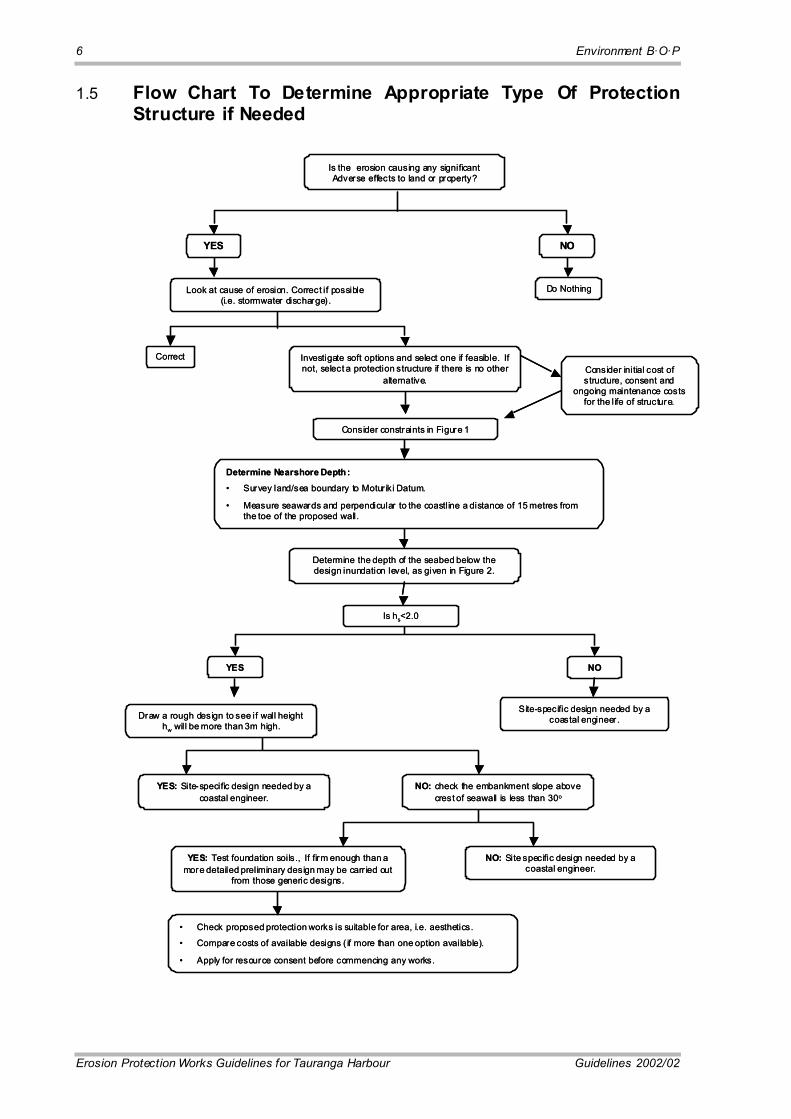
1.5 Flow Chart To Determine Appropriate Type Of Protection Structure if Needed
Is the erosion causing any significant Adverse effects to land or property?
YES NO
Look at cause of erosion. Correct if possible (i.e. stormwater discharge) .
Do Nothing
Correct Investigate soft options and select one if feasible. If not, select a protection structure if there is no other
alternative.
Consider constraints in Figure 1
Consider initial cost of structure, consent and
ongoing maintenance costs for the life of structure.
Determine Nearshore Depth:� Survey land/sea boundary to Motur iki Datum.
� Measure seawards and perpendicular to the coastline a distance of 15 metres from the toe of the proposed wall.
Determine the depth of the seabed below the design inundation level, as given in Figure 2.
Is hs<2.0
YES NO
Draw a rough design to see if wall height hw will be more than 3m high.
Site-specific design needed by a coastal engineer .
NO: check the embankment slope above crest of seawall is less than 30o
YES: Site-specific design needed by a coastal engineer.
YES: Test foundation soils., If firm enough than a more detailed preliminary design may be carr ied out
from those generic designs.
NO: Site specific design needed by a coastal engineer.
� Check proposed protection works is suitable for area, i.e. aesthetics.
� Compare costs of available designs ( if more than one option available).
� Apply for resource consent before commencing any works.
Environment B·O·P 7
Guidelines 2002/02 Erosion Protection Works Guidelines for Tauranga Harbour
The above is a simple diagram that shows the process that should be followed when considering the need for a structure to be built. It is an indicative diagram only and is supported by chapter 5 and the remainder of the document.
For your convenience a copy of Environment B·O·P�s �Applying for a Coastal Permit� brochure is included at the back of this document.
1.6 The Nature of the Coastal Erosion Process as an Environmental Phenomenon
The coast is the transition zone between the terrestrial environment and the maritime environment. As such it is incessantly subject to erosive and formative processes that are unique to such a zone of transition. It is inherently unstable due to the fact that it is being acted upon by a constantly changing input of energy from various sources. These sources manifest themselves as sea levels that may vary according to the tidal cycle, longer-term climatic cycles as well as short-term cycles due to the input of wave borne energy caused by wind.
What happens at a particular location, subject to a particular input of energy, will depend on the geological and geomorphological properties of the site and its ability to withstand the erosive forces. Ocean currents will also play a part and may either add sediments to a site or carry them away. Impact due to human activity may serve to disrupt the balance established over time.
The processes of coastal erosion are not fully understood or explained in terms of physical laws or mathematical models. The complex nature of these processes put their consideration outside the scope of guidelines such as these. It is because of these complexities that in many cases sea walls will need specialist design.
Experience accumulated over many years has shown that the erosive power of the ocean is less, the milder or flatter the slope of the beach is at the problem site. This is due to the fact that the amplitude of an ocean wave is limited, or attenuated, by the depth available in which to propagate. For the same beach profile, the wave energy input (amplitude) is higher if the length of fetch is more. These two factors, namely wave energy and the nearshore depth, if limited, permit the use of standard designs for coastal protection works in lesser erosive circumstances.
1.7 Do I Need a Consent?
1.7.1 Regional Council Controls
The construction of erosion protection works involves a number of component activities that will vary for different proposals. Seaward of the line of mean high water springs authorisation is required (Resource Management Act 1991) for the following:
• Structures
• Disturbance of the foreshore or seabed
• Deposition on the foreshore or seabed
8 Environment B·O·P
Erosion Protection Works Guidelines for Tauranga Harbour Guidelines 2002/02
• Introduction of exotic plants
• Occupation of Crown land
• Removal of sand or other natural material.
These activities require consent from Environment B·O·P and are generally Discretionary activities in the Bay of Plenty Regional Coastal Environment Plan. There are some exceptions, particularly in ecologically sensitive areas, and you should identify the activity status in the plan or discuss with a council officer prior to carrying out your design.
Depending on the size and scale of the proposed structures, a number of other resource consents may need to be applied for, these may or may not include:
• Earthworks consents (Bay of Plenty Regional Land Management Plan)
• Discharge Consents (particularly stormwater).
1.7.2 District Council Controls
Both Tauranga District Council and Western Bay of Plenty District Council have obligations under the Resource Management Act 1991 to control land use landward of MHWS (below that is in the jurisdiction of Environment B·O·P). This includes the placement of seawalls and any earthworks, movement or displacement of materials, occupation of the foreshore above MHWS with coastal protection works and any maintenance and landscaping of the seawalls.
The District Council may also be the owner of the land (esplanade reserve) in which case you will need their permission as owner.
1.7.3 Department of Conservation
The Department of Conservation has a number of responsibilities in the coastal marine area, including statutory advocacy (i.e. providing a conservation perspective on the development of regional plans and district plans and on the consideration by councils of consent applications).
The department also has the responsibility to service the Minister of Conservation in his or her functions and duties under the Resource Management Act. This includes making decisions on permit applications for restricted council activities in the coastal marine area. The Minister of Conservation represents the Crowns� interest in the management of these lands within the coastal marine area for which the Crown has vested ownership to itself through various types of legislation.
9
Guidelines 2002/02 Erosion Protection Works Guidelines for Tauranga Harbour
Chapter 2: Results of Harbour Erosion Investigations
In order to achieve a focused approach to the various aspects of the problem, four separate consulting firms were commissioned, to investigate the problem from four different perspectives.
2.1 Coastal Consultants
The firm Coastal Consultants NZ Limited was contracted to assess the effects of existing coastal protection works on geomorphic processes in the Tauranga Harbour Estuary.
The aim was to put the current problem into perspective. In order to get the full benefit of this investigation, the reader is encouraged to refer to the full report, a summary of which is provided below.
In Chapter 1 Coastal Consultants New Zealand Limited�s brief is outlined. They were to investigate whether the existing coastal protection works (of which there are more than 1,000) have had any significant effects on the coastal geomorphological processes in the harbour and if so, to what extent.
Chapter 2 of the report briefly reviews the current knowledge about the interaction between seawalls of various designs, and coastal processes and geomorphology. Results and conclusions of studies worldwide are presented detailing the potential adverse effects on the physical environment as a result of seawall construction.
Chapter 3 sets out the methodology used to study the Tauranga Estuary seawalls themselves, in order to get an insight into the nature of the local problem. A range of sites were selected representing the different types of harbour characteristics. At each sites measurements were taken of alongshore variations in bed level and an assessment of the performance of individual structures.
Chapters 4 and 5 present the results of the field investigations carried out and then attempts to identify common trends in the effects of structures on the geomorphological processes involved. The major effect identified was the lowering of the seabed level in front of the structures. The analysis is well documented with photographs of the various situations that exist in the estuary.
The results obtained relative to nearshore bed level change and the degree and type of coastal protection, were as follows:

10 Environment B·O·P
Erosion Protection Works Guidelines for Tauranga Harbour Guidelines 2002/02
(i) Unprotected sections of coast were consistently found to have the highest observed bed levels (i.e. the least scour).
(ii) Protected sections of coast were found to have markedly lower bed levels (up to 0.4 � 0.8m lower) than unprotected sections of coast.
(iii) The magnitude of bed level lowering is related to structure type.
• lowest bed levels were observed in front of vertical seawalls
• bed levels in front of sloping structures were higher than in front of vertical structures and lower than unprotected sections of coast.
(iv) Observed bed level lowering occurred irrespective of the material comprising the structures (e.g. wood or concrete).
Further tentative conclusions reached are the following:
(i) Use of hard structures to combat shoreline erosion will produce a reduction in bed level of the nearshore in the medium to long-term.
(ii) At sections of coast where the rate of shoreline erosion is known to be high (as identified by individual site investigations) bed lowering can be expected to be greater in magnitude and occur over shorter timescales.
(iii) While it is desirable that beaches are maintained, this is unlikely to occur in front of structures where sediment supplies are limited.
(iv) The presence of structures normal to the shoreline (e.g. groynes) can reduce the magnitude of bed lowering caused by the insertion of hard structures parallel to the shore.
(v) Where possible, natural cliff processes should be allowed to continue, to supply sediment to the nearshore. Toe protection (using hard structures) of entire cliffed coastlines is undesirable with respect to maintaining natural coastal processes and will exacerbate bed level lowering of the nearshore.
(vi) Where possible, surface water drainage should be directed away from the shoreline, in order to avoid further scour and bed level lowering of the nearshore environment.
(vii) From a management perspective the presence of foreshore vegetation has beneficial effects for offsetting bed level lowering associated with hard structures. Further, vegetation has the potential to be used as an erosion management tool in lower energy settings.
(viii) With regard to coastal processes, seawalls do aid in preventing cliff failure. However, total protection of cliffs will severely limit sediment supply to the nearshore and promote longer-term reduction in bed level.
In summary it is concluded that existing structures do have an impact on local geomorphic processes (as reflected in bed level lowering). However the magnitude of impact is small and is not considered to represent a serious adverse effect, in the context of harbour protection as a whole.

Environment B·O·P 11
Guidelines 2002/02 Erosion Protection Works Guidelines for Tauranga Harbour
Observed effects of structures were localised only and were not found to have an aggregate effect on Tauranga Harbour at a regional scale.
Under projected sea-level rise scenarios, unprotected sections of coast are expected to be translated landward. This will exacerbate the �scalloped� effect of the shoreline configuration. It is anticipated that bed levels in front of existing structures will further decline as sea level rises.
2.2 Tonkin and Taylor
2.2.1 Introduction
The firm Tonkin and Taylor was commissioned with the objective of providing recommendations that would aid in the selection of an appropriate coastal protection structure in the Tauranga Harbour, in cases where a hard engineering solution is the most suitable.
2.2.2 Scope
The scope of the study done by Tonkin and Taylor was to develop common construction standards for harbour margin protection works for typical shoreline structures in Tauranga Harbour. The study was also to identify and provide direction as to when hard engineering solutions should be implemented. It was envisaged that the following would be taken into account:
• The location of the site of the works in terms of its susceptibility to damage by wave height, storm surge and rising sea level.
• The construction options that may be available depending on location, topography, foundation conditions, existing structures, public access to and usage of the foreshore area.
• Past deficiencies and problems.
• Criteria for determining which design option is recommended for a particular site. (�site� being loosely defined as an area where geomorphic characteristics are similar).
• The actual construction specifications (material, construction methods, workmanship standards etc.) of each option.
• Integration with existing works.
• Ongoing maintenance and repair of structures.
• Design Life � Life Cycle Costs.
2.2.3 Main Results
The main results of the Tonkin and Taylor report are the six generic designs that they present as possible options for a �hard� solution. A selection methodology is given to determine whether any of the six �standard� designs are appropriate to the site. If
12 Environment B·O·P
Erosion Protection Works Guidelines for Tauranga Harbour Guidelines 2002/02
not, a site-specific design is needed by a specialist coastal engineer. Any design for a site where the design risk is to be less than 2% AEP (that is to have a design return period exceeding 1 in 50 years) is also excluded from handling by means of any of the �standard� designs. The Tonkin and Taylor report also notes that there are alternative solutions to the problem of coastal erosion, but these need site specific assessment and design by a specialist coastal engineer. Groynes and sand sausages are examples of these.
It is noted that the standard designs are intended for coastal erosion protection works and should not be used for designing retaining wall structures.
The report contains a detailed methodology on how to apply the recommended procedures. This is covered in Chapter 5 of these Guidelines, entitled �Procedure Recommended for using these Guidelines� and will not be repeated here.
2.2.4 Disqualifying Factors
If any of the following factors apply to a problem site, none of the standard designs will be appropriate without specific design by a coastal specialist:
• The works are located on a headland or promontory.
• The works are located near a river/stream, or on the banks of a river/stream.
• If the nearshore water depth hs, below the applicable design inundation water level, exceeds 2.0 m.
• If the geotechnical investigations conclude that the soils are �soft� (less than 2 blows per 50 mm from scala penetrometer testing).
• If the embankment slope above the crest of the seawall is greater than 30 degrees.
• If the required wall height (hw) is found to be higher than 3m after doing the preliminary design.
• If the problem site is located in any area identified on Figure 2 as an area where site-specific assessment is required.
• If the design risk is for an event more severe than that associated with the 2% AEP event.
• If the total length of coastline affected by protection works exceeds 40m, including the length of adjacent works.
The depth hs and height hw is measured as defined in Section 5.2. For a graphical illustration of the use of the design parameters hs and hw, see Figure 1.

Environment B·O·P 13
Guidelines 2002/02 Erosion Protection Works Guidelines for Tauranga Harbour
2.2.5 Some Common Deficiencies of Structures
The Tonkin and Taylor report points out some common deficiencies found in seawalls/revetments as a result of implementing the wrong structure type, or due to inadequate design or construction. These include:
• Failure to provide adequate toe protection of the structure so that it will not be undermined.
• Failure to provide seawall returns at the ends of the seawall/revetment that serve to reduce end erosion effects.
• Inadequate design of structures that are founded on soft foundation material.
• Failure to use rock of suitable size, grading and density.
• In areas where the backshore area is higher than the seawall crest, failure to extend the seawall high enough, resulting in overtopping from the seaward side leading to scour of the backshore area.
• Failure to ensure that voids between individual pieces of the armour layer are small enough, so that the underlying filter material is not washed out by waves.
Many of these findings are consistent with the findings of �Coastal Consultants�.
2.2.6 The Generic Designs, their Impact, Durability and Suitability
Table 2.2.6 below lists the six generic designs presented by Tonkin and Taylor for use (within limits) by qualified engineers, who are not coastal specialists.
These options, together with the wave energy levels that they should be able to withstand, and their expected design lives, are:
Table 2.2.6 Coastal Protection Options
High Energy Medium Energy Low Energy Design Life Years
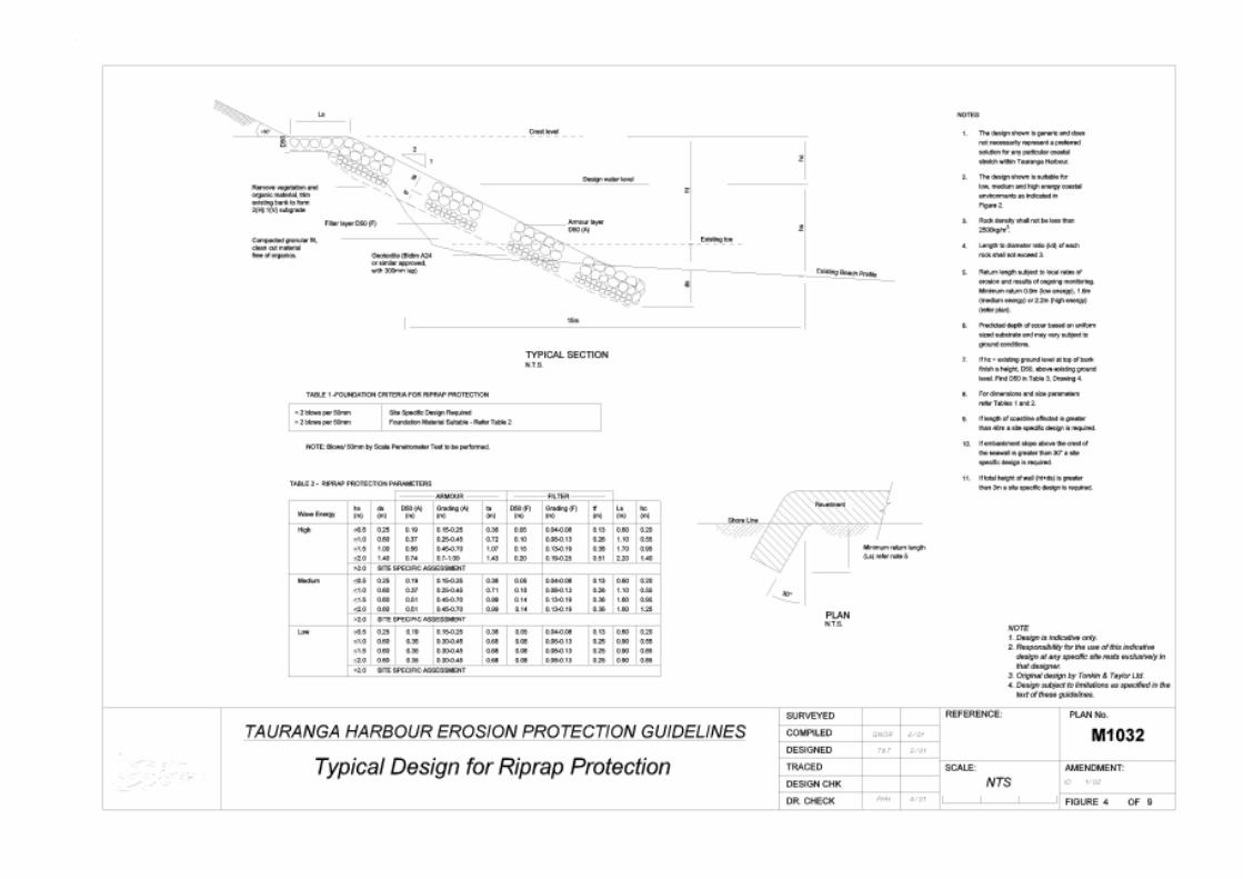
Riprap Revetments Yes Yes Yes 30 to 100
Grouted Seawalls Yes Yes Yes 20 to 50+
Timber Seawalls No Yes Yes 20+
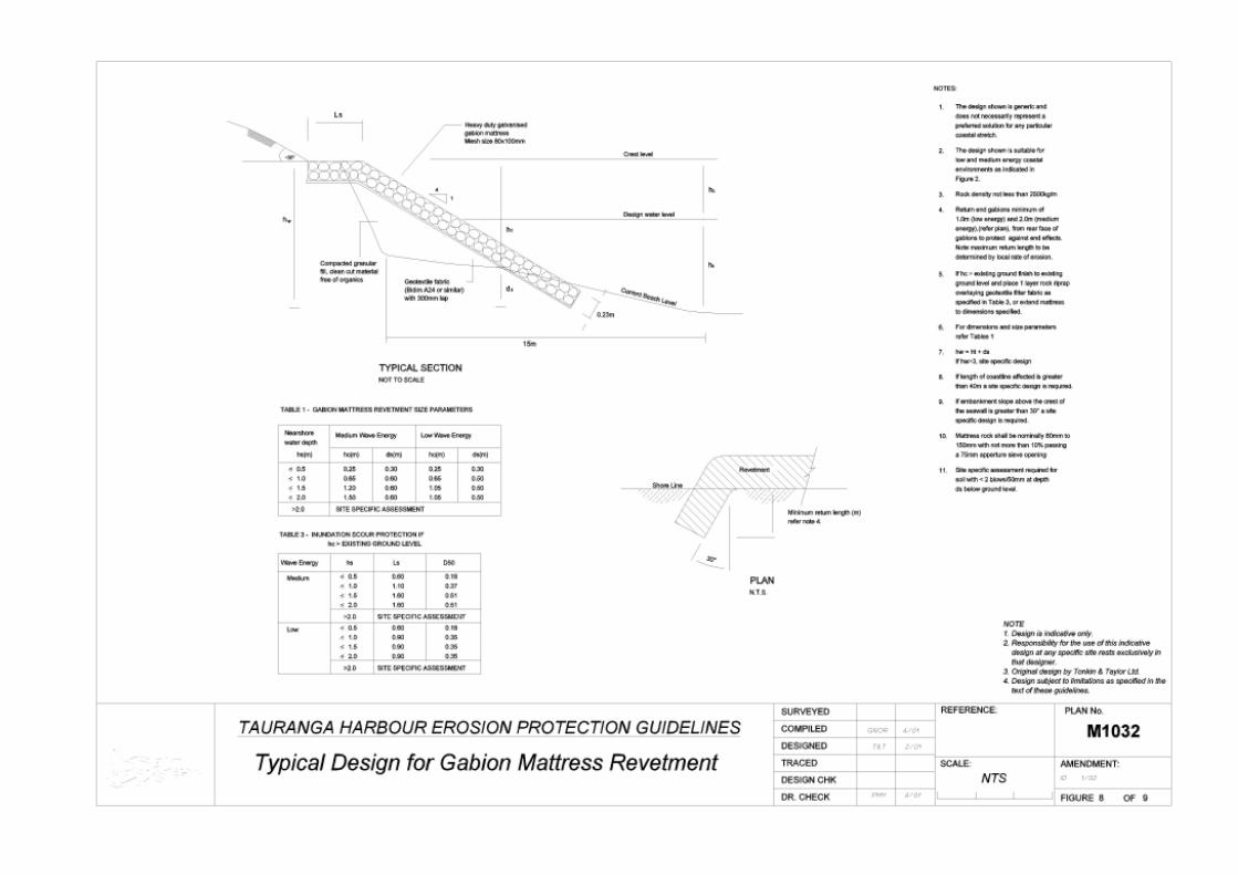
Gabion Seawalls (Basket or mattress) No Yes Yes 5 to 20
Offshore Reef Breakwaters Site Site Yes 20 to 50
Site = Site specific design required
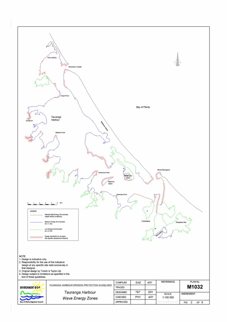
The wave energy zones referred to above are shown in Figure 2.
14 Environment B·O·P
Erosion Protection Works Guidelines for Tauranga Harbour Guidelines 2002/02
The report warns that there is still a possibility of adverse effects taking place, even in the case of the �standard� options and that it should be noted that in coastal hydraulics (including the proposed six standard designs) success is not necessarily guaranteed. This risk is, however, so small that if the standard design is adhered to, coastal specialist advice is not necessary.
For the cases of Riprap Revetments, Grouted Seawalls, Timber Seawalls and Gabion Seawalls the following adverse effects are possible:
• Construction impacts.
• Beach lowering immediately fronting the structure.
• Depending on the locality of the structure and limitations on seawall height above the design water level, possible scour landward of the structure may occur during significant storm events due to wave run-up and overtopping. However, this can be mitigated in the design by the provision of a masonry inundation apron and by the use of a 3m wide planting zone landward of the structure.
• Erosion at the ends of the seawalls may occur due to end effects.
• The neighbouring unprotected shoreline adjacent could continue to erode.
• Visual effects.
Adverse effects associated with the Offshore Breakwaters are relatively low, as these structures are designed for low energy environments only. The main limitations are:
• Construction impacts.
• Possible beach lowering immediately fronting the structure.
• Possible scour to the backshore area and disruption to vegetation during significant storm events.
Groynes are not covered by these guidelines as a standard design because of the potential for adverse effects and the need for specific design, as detailed by Tonkin and Taylor and Coastal Consultants NZ Ltd. It is clear, however, that groynes do merit consideration as a possible solution at times, but only for design by specialists.
The Tonkin and Taylor report provides a selection method, for an appropriate structure, from amongst the standard options. This is set out in paragraph 5.1.
For each of the six options, the procedures to be followed, pertaining both to design as well as to construction procedures, are given, as well as construction material specifications and matters referring to maintenance.
Charts showing the Wave Energy Zones into which the estuary has been divided are given (Figure 2).

Environment B·O·P 15
Guidelines 2002/02 Erosion Protection Works Guidelines for Tauranga Harbour
Matters not mentioned in this section, but also deriving from the Tonkin and Taylor report, are set out in Chapter 5 along with the recommended procedure for the use of these guidelines, to avoid duplication.
2.3 Opus International Consultants
2.3.1 Introduction
Environment B·O·P commissioned Opus International Consultants Ltd (Opus) to undertake a literature review to investigate �soft� options as an erosion protection mechanism in harbour and estuarine (low energy) environments. �Soft� options were taken to include such things as beach nourishment and revegetation, but exclude �hard� (or structural) options, e.g. revetment or seawall construction.
2.3.2 Scope
The scope and nature of the services was to undertake a literature review encompassing both New Zealand and overseas examples of the use of soft options or other relevant options in the minimum to medium intervention categories as erosion protection mechanisms in harbour and estuarine (low energy) environments.
The results of the literature search were presented in a report, along with findings on:
• Protection measures suitable to Tauranga Harbour.
• Data on risk/cost/benefit found as part of the study.
• Suggestions for appropriate trials to be done in the Tauranga Harbour and estuary area.
When considering any coastal protection method, the coastal and estuarial processes (wind, waves, currents, tides, sediment transport, etc) in the area need to be understood and evaluated along with the costs, risk and benefits of the scheme. Discussion and consideration of these factors was outside the scope of the literature review. Further information on works that have been carried out in the Tauranga Harbour was given in an Appendix to the report of the study.
2.3.3 Main Results
A summary of the �soft� protection options discussed in the literature review report is given in table 2.3.3, together with an assessment of their applicability for use in the Tauranga Harbour. Where possible to determine, the cost of these options as a proportion of the structural protection cost is included, as is an indication of further assessment, trials etc recommended to be carried out.

16 Environment B·O·P
Erosion Protection Works Guidelines for Tauranga Harbour Guidelines 2002/02
Table 2.3.3: Summary of Applicable �Soft� Protection Methods for Use in the Tauranga Harbour.
Option Suitable for Use in the Tauranga
Harbour1
Cost, as a proportion of
Structural Protection Cost2
Further Assessment, Trials etc
Recommended3
Soft Structural Options
Beach Nourishment Shoref ace Nourishment Sand Dam Construction
Yes No Yes
25 % Yes Yes
Beach Scraping No No
Rev egetation Yes �Order of magnitude less� Yes
Dune and Back Beach Reconstruction Yes, depending on shoreline 30%
Conf iguration Dredging Probably no No Beach Dewatering Probably no No Modif ication of Slope Prof ile Yes Yes Semi-Soft� Structural Options Sand-f illed Geotextile Headlands, Nearshore Breakwaters and Groynes Yes 30% - 50% Yes
Used Ty re Breakwaters or Seawalls No No Dune Construction and Beach Nourishment with Buried Rev etment Yes 80% No
Timber Groy nes with Beach Nourishment Yes No 1 From preliminary assessment using available information. 2 Where these comparative costs are available. 3 With site-by-site applicability taken into account.
2.4 Isthmus Group
Isthmus Group Landscape Architects were commissioned by Environment B·O·P to undertake an assessment of landscape, amenity and public access effects of coastal harbour protection works in Tauranga Harbour.
The study is an assessment of the landscape, visual, amenity and access effects of selected types of harbour protection works with regard to their potential application over a range of shoreline situations in the harbour.
Four types of protection works were evaluated for each landscape context. They were vertical walls, sloping walls, groynes and replanting. The report also includes various mitigation recommendations. This includes general landscape treatments for protection works to facilitate public access and to avoid, remedy or mitigate adverse effects.
The land use types that were studied were the Central Business District, Urban Industrial, Suburban, Lifestyle blocks, and Rural/Farm/Orchard and Conservation areas. The report identifies the characteristics of the particular areas such as the landscape character; amenity values, public assess issues and preferred building materials. Each protection type was then assessed as to its environmental impact and suitability for the area. This information was then presented in table form and is included in Chapter 3 of this report.

17
Guidelines 2002/02 Erosion Protection Works Guidelines for Tauranga Harbour
Chapter 3: Avoid, Remedy or Mitigate Before designing and building a coastal protection structure is it important that the potential effects on the area are studied. Building a structure in an estuary area is likely to have greater effects than building a structure in an urban area. It is therefore very important that the surrounding landscapes and the values placed upon them are given consideration during the planning and design process. Amenity values are those physical qualities and characteristics of an area that contribute to people�s appreciation of its pleasantness, aesthetic coherence, and cultural and recreation attributes. Similar to amenity values are aesthetic values where those landscapes and natural features that are deemed of high aesthetic value are determined on their value, their naturalness and on their composition, coherence and blending together. The Regional Coastal Environment Plan reinforces the need to protect landscape qualities with the following:
Coastal Plan Policies
5.2.3(g) To protect the cumulative landscape qualities of channels, tidal flats, beaches, coastal margins, vegetation and the land backdrop.
5.2.3(h) Reclamations and seawalls must reflect natural coastal landflows (curves, embankments and headlands) rather than straight lines and rectangular shapes.
5.2.3(i) New development should be of a design, materials and colours which blend the development with the surrounding environment, and maintain amenity values. Markers or high visibility materials may be required for safety where relevant.
When resource consent is applied for the applicant will need to show that they have taken into account both the positive and negative effects of the coastal erosion protection works. If the applicant has taken steps to �blend� the coastal protection with the surrounding landscape and taken into account both amenity and aesthetic values then this part of the process may be potentially easier. The applicant must also show that they have examined all of the possible alternatives to the building of the seawall. Should a �soft� option provide a better level of protection as well as blending into the surrounding environment then the �soft� option should be the preferred one.
18 Environment B·O·P
Erosion Protection Works Guidelines for Tauranga Harbour Guidelines 2002/02
These soft options may include (but are not limited to) the following:
• Purchase land, to allow for retreat over time.
• Beach replenishment by way of imported aggregates or sands.
• Introduction of a Best Management Practice regime which may comprise partly of replenishment and partly in restricting access, as well as other appropriate components. This may be sufficient to mitigate the possible cause of the erosion, especially if it is caused by some external or human intervention such as traffic or other disturbances.
• A programme of Planned Rehabilitation by way of introduction of suitable vegetative stabilisation.
• Construction of one or more stabilising structures coupled with replenishment and/or any of the above. (This is a semi hard option however.)
• Any request for a solution by way of a hard option must be accompanied by an explanation of why the soft options are considered inadequate.
The first �soft� option that should be considered however, should be the �do nothing� option. If the consequences of following this option will result in further, or more intensified erosion that must be contained, then we first need to consider other soft options and if need be, hard options should then be considered.
It should be noted however soft options such as shoreline stabilisation through the planting of suitable vegetation is only feasible in relatively low energy input settings.
There is considerable evidence that the lesser the sea-facing slope of a structure is, with respect to the horizontal, the lesser will be the depth of scour in the ocean bed immediately fronting the sea wall. A well-designed Rip Rap Revetment protection wall is therefore �softer� on the environment than a timber seawall, which by its nature is more vertical.
Another important factor when weighing up different options (including hard options) against each other is the fate of the remnants of the works at the time they become unserviceable.
In the longer term (between 5 � 100 years) all seawalls not founded on rock, are unstable and will fail in a structural sense, most likely due to scour below foundation.
If this happens the remnants of the works may well be very unsightly. The grouted stone seawalls, may disintegrate over time, the baskets of the gabions are also at risk due to deterioration of the containing wire mesh.
Seawalls such as offshore breakwaters or revetments made of rip-rap layers offer the best chance of achieving medium term protection, and at the same time avoiding the real possibility that the coastal zone deteriorates aesthetically. Even if they were to sink deeper with time, they could still serve as foundations for further rock on top of them and the visual evenness of the rock is usually aesthetically acceptable.
The Tauranga Harbour area is nationally significant as a result of its natural features and its recreational and other values. It is also an aim of these guidelines to implement standards that will not compromise these features and values in any way.
Environment B·O·P 19
Guidelines 2002/02 Erosion Protection Works Guidelines for Tauranga Harbour
3.1 The Impacts of Erosion Works on the Major Landscapes in the Tauranga Harbour Region
The following pages show examples of the various landscapes in the Tauranga Harbour region and their various characteristics. This also shows the values that are generally attributed to an area and how highly regarded they may be as a visual asset to the public.
If a coastal erosion protection work is needed for an area then it is preferable that the most appropriate method of erosion protection is used. This must be from an engineering perspective as well making sure that the form of protection fits in with the surrounding landscape and that appropriate materials are used.
There are a number of areas that should be checked before the engineering and design of a coastal erosion protection work is undertaken:
• Decide if the method of protection is appropriate for the area, for instance a concrete wall in an urban area is appropriate but a concrete wall in an estuary area is not appropriate.
• Choose materials that fit in with the surrounding landscape and existing seawalls. If the proposal is to continue an existing seawall try and make sure that the materials match as much as possible to avoid further cumulative effects.
• Follow the coastline to the greatest extent possible. It is not advisable to have many small and abrupt changes, as curves need to be smooth and long to prevent wave reflection problems.
• Remember that there are many users of the Tauranga Harbour area and make sure that all access and amenity values are protected.
Chapter 4 outlines a number of General Procedures to Control the Effects on Amenity and Enjoyment Values.
The following section gives a brief outline as to the factors that must be taken into account in the various areas and the tables show the most visually appropriate methods of erosion controls to use in particular areas should they be necessary.
3.2 Central Business District
3.2.1 Landscape Character:
Highly developed, human presence dominant, surfaces hard and impervious; angular forms; modified environment. Refer to Appendix I, assessment of materials, for further information on appropriate materials for use in this environment.

20 Environment B·O·P
Erosion Protection Works Guidelines for Tauranga Harbour Guidelines 2002/02
3.2.2 Amenity Values:
Views of the water and water activity are important; the edge must be well protected from potential damage to ensure safety of buildings; the built edge is frequently higher than the water level so public safety along the edge is important.
3.2.3 Public Access Issues:
Physical access to water is a priority. Disabled access is also a priority. Wide walkways, ramp access, and wide steps are important.
3.2.4 Materials
Masonry, rock (refer Appendix I).
3.2.5 Sensitivity
Refer to Appendix II, sites of special sensitivity, for areas requiring special consideration.
Protection type Harbour edge type Vertical Sloping Groynes Replanting Cliff Appropriate; provide
access along top of wall if needed
Appropriate; provide access along top of wall if needed
Not appropriate; visually prominent
Appropriate in combination with other methods
Bank Treat wall as retaining wall provide access along top of wall
Provide access along top and through wall to water
Not appropriate visually prominent
Appropriate; either alone or in combination with wall
Beach Appropriate; low wall not less than 500 mm preferred; provide access to beach and water people and boats
Not appropriate vertical wall preferred because loss of beach reduced
Not appropriate; use of beach and water difficult; visually prominent in view across water
Appropriate if access to water not required, or not restricted where required
Estuary Not appropriate Not appropriate Not appropriate Appropriate
3.3 Urban Industrial
This category includes the port, airport and other large industrial activities.
3.3.1 Landscape Character:
Highly developed, human presence dominant, surfaces hard and impervious; angular forms; highly modified environment including sea edge; very large scale of built form; often the edge may be created by human activity e.g. wharf.
3.3.2 Amenity Values:
Views across the water to activity important to public: built edge is used for commercial purposes: public access along edge is discouraged and undesirable.

Environment B·O·P 21
Guidelines 2002/02 Erosion Protection Works Guidelines for Tauranga Harbour
3.3.3 Public Access Issues:
Physical access to water by public is not a priority.
3.3.4 Materials
Masonry, rock (refer Appendix I).
3.3.5 Sensitivity
Refer to Appendix II, sites of special sensitivity, for areas requiring special consideration.
Any changes or modifications to the harbour edge should only be undertaken following a site-specific design process, and therefore general recommendations are not included. Appendix I contains information on recommended materials for this context.
3.4 Suburban
3.4.1 Landscape character
Moderate level of development, predominantly housing visible along the harbour edge: the human presence is obvious but modulated by gardens; surfaces are a mix of soft and hard; smaller scale forms; modified environment. Appendix I contains recommendations for materials to use in this area.
Amenity values: Views of water and water activity very important to homeowners; there is a perception that the harbour edge needs reinforcing to protect houses and land; visual access to water a priority for homeowners and public.
3.4.2 Public access issues:
Physical access to water a priority; this includes both beach access and walkway access.
3.4.3 Materials
Stone, rock, timber (refer Appendix I).
3.4.4 Sensitivity
Refer to Appendix II, sites of special sensitivity, for areas requiring special consideration.
Protection type Harbour edge type Vertical Sloping Groynes Replanting Cliff Appropriate;
provide access along top
Appropriate; provide access along top
Not appropriate; visually prominent
Appropriate particularly in combination with other options
Bank Appropriate; id
Appropriate; id
Not appropriate i ll i
Appropriate

22 Environment B·O·P
Erosion Protection Works Guidelines for Tauranga Harbour Guidelines 2002/02
Protection type Harbour edge type Vertical Sloping Groynes Replanting
provide access along top
provide access along top
visually prominent, obstructs access at waters edge
Beach Appropriate; less than 500 mm preferred; provide through wall for boats and people
Appropriate; if it doesn�t encroach on beach; provide access points through wall
Not appropriate; visually prominent, obstructs use, access
Appropriate if doesn�t restrict access and use
Estuary Not appropriate Not appropriate Not appropriate Appropriate
3.5 Lifestyle Block
Large lots whose primary purpose is to provide amenity and lifestyle for owners, rather than production for income.
3.5.1 Landscape character
Low density development; dominance of open space; planting and soft surfaces dominate; small scale forms.
Amenity values:
Views of water and water activity are important to property owners; private access to water a priority; maintenance of open space, views and semi-rural character are priorities.
3.5.2 Public access issues:
Physical access to water a priority but generally through reserves; beach and walkway access highly desirable.
3.5.3 Materials
Stone, rock, timber, estuarine replanting, sand (refer Appendix I).
3.5.4 Sensitivity
Refer to Appendix I, sites of special sensitivity, for areas requiring special consideration.
Protection type Harbour edge type Vertical Sloping Groynes Replanting Cliff Appropriate; provide
access along top of wall if required to connect existing walkways
Appropriate; provide access along top of wall if required to connect existing walkways
Not appropriate; visually prominent, impedes access along water�s edge
Appropriate
Bank Appropriate; provide access if required
Appropriate; provide access if required
Not appropriate visually prominent,
Appropriate
Environment B·O·P 23
Guidelines 2002/02 Erosion Protection Works Guidelines for Tauranga Harbour
Protection type Harbour edge type Vertical Sloping Groynes Replanting
impedes access along water�s edge
Beach Appropriate: provide access; wall height less than 500 mm preferred
Appropriate: doesn�t encroach on beach; provide access points through wall
Not appropriate; visually prominent, impedes use of beach and water
Appropriate if doesn�t restrict access and use
Estuary Not appropriate Not appropriate Not appropriate Appropriate
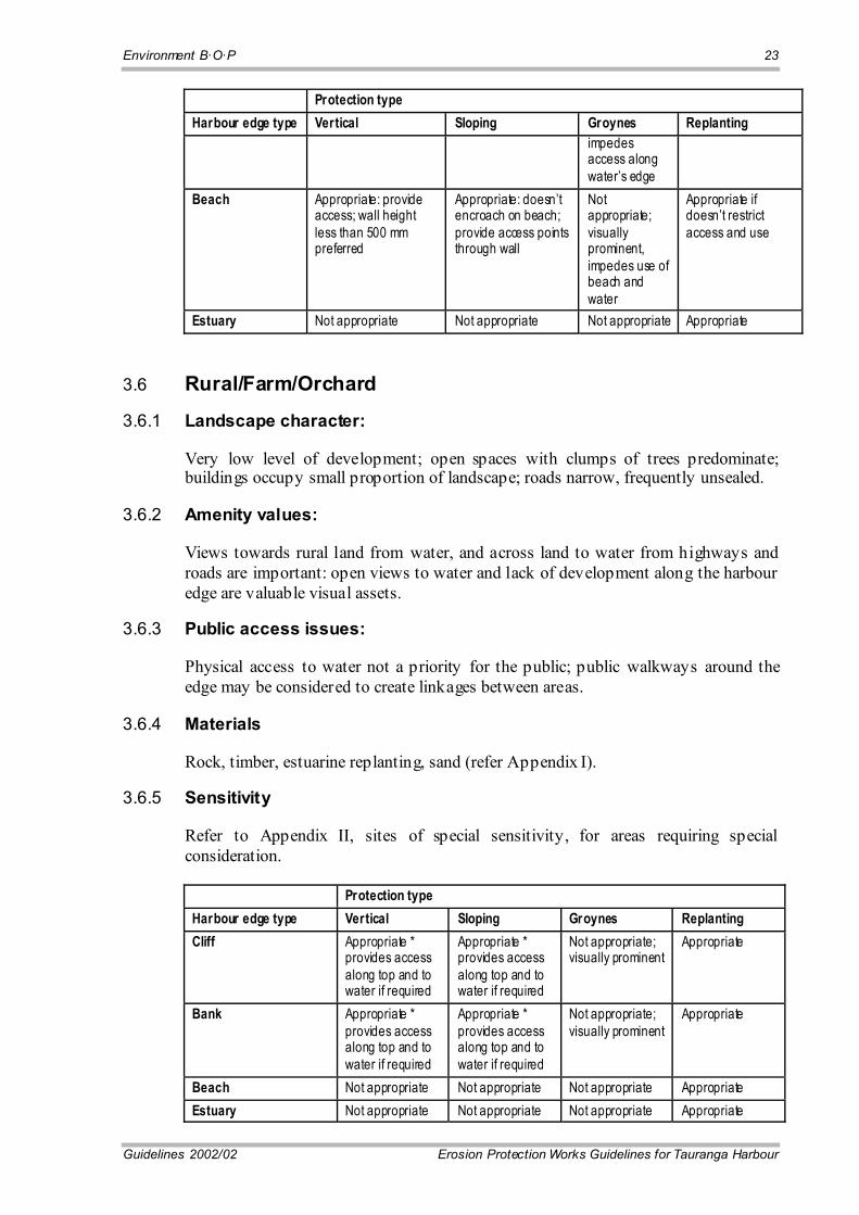
3.6 Rural/Farm/Orchard
3.6.1 Landscape character:
Very low level of development; open spaces with clumps of trees predominate; buildings occupy small proportion of landscape; roads narrow, frequently unsealed.
3.6.2 Amenity values:
Views towards rural land from water, and across land to water from highways and roads are important: open views to water and lack of development along the harbour edge are valuable visual assets.
3.6.3 Public access issues:
Physical access to water not a priority for the public; public walkways around the edge may be considered to create linkages between areas.
3.6.4 Materials
Rock, timber, estuarine replanting, sand (refer Appendix I).
3.6.5 Sensitivity
Refer to Appendix II, sites of special sensitivity, for areas requiring special consideration.
Protection type Harbour edge type Vertical Sloping Groynes Replanting Cliff Appropriate *
provides access along top and to water if required
Appropriate * provides access along top and to water if required
Not appropriate; visually prominent
Appropriate
Bank Appropriate * provides access along top and to water if required
Appropriate * provides access along top and to water if required
Not appropriate; visually prominent
Appropriate
Beach Not appropriate Not appropriate Not appropriate Appropriate Estuary Not appropriate Not appropriate Not appropriate Appropriate

24 Environment B·O·P
Erosion Protection Works Guidelines for Tauranga Harbour Guidelines 2002/02
* Special note: Rural land provides one of the few remaining opportunities to break up the fortification of the harbour edge. No protection works should be constructed in these areas unless absolutely necessary. The term "appropriate" applies only to the visual, access and amenity qualities of a type of protection. It should not be understood to mean that the protection itself is either appropriate or necessary.
3.7 Conservation
3.7.1 Landscape character:
Absence of development; dominated by vegetation, wildlife and water in natural condition; sense of humans as visitors.
3.7.2 Amenity values:
Educational and recreational uses for study and enjoyment of wildlife, vegetation; quiet and peacefulness; slow pace of movement (walking dominant, not vehicular).
3.7.3 Public access issues:
Physical access to water a high priority in non-estuarine areas (e.g. rocky coastal areas); ability to walk for some distance at or near water's edge highly desirable except where incompatible with flora and fauna protection; vehicle access restricted or limited.
3.7.4 Materials
Estuarine replanting (refer Appendix II). 3.7.5 Sensitivity
Refer to Appendix I, sites of special sensitivity, for areas requiring special consideration
Protection type Harbour edge type
Vertical Sloping Groynes' Replanting
Cliff Appropriate * provide access to water�s edge
Appropriate * provide access to water�s edge
Not appropriate; visually prominent
Highly appropriate
Bank Appropriate * provides access to water�s edge
Appropriate * provides access to water�s edge
Not appropriate; visually prominent
Highly appropriate, also in combination with other options
Beach Not appropriate Not appropriate Not appropriate Highly appropriate Estuary Not appropriate Not appropriate Not appropriate Highly Appropriate
* Special Note: Protection works in conservation land should be avoided unless absolutely necessary. The dominance of natural processes operating in these areas is vital to their ability to sustain their conservation function and protection works will interfere with these processes. The term "appropriate" applies only to the visual, access and amenity qualities of a type of protection. It should not be understood to mean that the protection itself is either appropriate or necessary.

Environment B·O·P 25
Guidelines 2002/02 Erosion Protection Works Guidelines for Tauranga Harbour
Section 5.4 Recommends the quality of materials to be used in the building of protection works.


27
Guidelines 2002/02 Erosion Protection Works Guidelines for Tauranga Harbour
Chapter 4: Managing Effects on Environmental Values
The entire Tauranga Harbour area is identified as an Outstanding Landscape as defined by the Resource Management Act 1991 section 6(b). Within the harbour however there is considerable landscape variation, and there are parts of the harbour area where any construction of protection works will have a great impact. To mitigate against any effects Chapter 4 covers a number of effects and cumulative effects and some suggested ways these can be mitigated. It is suggested that before the commencement of any building works the following should be considered.
* Note: Structures should always be maintained to consent standards.
4.1 Landscape and Visual Effects
Potential landscape and visual effects of coastal protection works include:
• Structures that are clearly visible from a distance.
• Structures that contrast with the existing form of the landscape or introduce forms unrelated to the landform.
• Structures that use materials unrelated to the context.
• Visual chaos resulting from mixtures of materials.
• Structures that interrupt views from the land towards the sea.
• Unsightly edges to beaches that interrupt views along beach and toward land.
• Broken structures poorly maintained.
To avoid, remedy or mitigate adverse landscape and visual effects:
• Structures should use dark coloured materials in general.
• Structures should be at the water line and extend only a minimum required distance above it.
• Structures should use materials appropriate to the landscape context e.g. refined and finished in urban areas, informal in more natural areas.

28 Environment B·O·P
Erosion Protection Works Guidelines for Tauranga Harbour Guidelines 2002/02
• Wherever possible the top edge of the structure should be flush with ground level behind.
4.2 Amenity and Enjoyment Effects
Potential amenity and enjoyment effects:
• Walls that occupy most of the available beach/sand surface.
• Piecemeal approach to protection that creates adverse effects for immediate neighbours e.g. incomplete protection at ends of walls creating erosion between wall sections.
• Construction of walls in areas where �soft� options are available.
• Introduction of hard structures in areas where experience of landscape and water is primarily natural.
Recommendations to avoid, remedy or mitigate adverse effects on amenity and enjoyment:
• Use vertical walls where required sited behind beaches to minimise loss of beach surface.
• Require comprehensive protection at vulnerable edges for complete distance of edge.
• Plant in front of walls wherever possible to reduce visual presence of walls, if planting is appropriate.
• Avoid walls in estuarine areas, use replanting.
�Plant in front of walls wherever practical to reduce visual presence of walls.�
4.3 Public Access Effects
Potential public access effects include:
• Structures that eliminate access to water through high walls.

Environment B·O·P 29
Guidelines 2002/02 Erosion Protection Works Guidelines for Tauranga Harbour
• Lack of provision for pedestrian access along waters edge.
• Lack of provision for pedestrian and vehicular access to water.
Recommendations to avoid, remedy or mitigate adverse effects on public access:
• Require all walls in areas where water edge access is possible to provide for this activity.
• Keep vertical walls very low along beach edges (less than 500mm height) to enable people to step down them.
• Provide steps at regular intervals along vertical walls along beaches (width, and number dependent on user numbers of beach).
• Provide boat ramps where vehicle access to water�s edge exists.
�Provide wide steps at regular intervals along vertical walls on beaches.�
4.4 Cumulative Effects
Cumulative effects can result from a combination of adverse effects, from incremental change over time, from inconsistencies in materials and design, and from the number and scale of the works.
There are a number of potential cumulative effects from a combination of landscape, amenity and access values:
• Demand for protected edges resulting in degradation of attractive beaches from increasing public pressure and better access.
• Conflicts between access demands and amenity values (e.g. wanting vehicle access to quiet and secluded bays), or between landscape values and access or amenity demands (e.g. providing access through pristine coastal forest or wildlife estuaries).
Potential cumulative effects from incremental change over time:
• Loss of quiet beach space from provision of increased boat/vehicle access.
• Loss of privacy to neighbours from increased public walking paths.

30 Environment B·O·P
Erosion Protection Works Guidelines for Tauranga Harbour Guidelines 2002/02
• Increase in total length of harbour edge protected by structures, and corresponding loss of naturalness.
Possible mitigation approaches include:
• Limiting boat and vehicle access to parts of the harbour, separate from quieter areas e.g. conservation areas and swimming beaches.
• Requiring screen planting in conjunction with construction of new walls to protect privacy of adjacent properties.
• Requiring alternative to hard protection along edges of new developments
• Keeping all new developments sufficiently distant from the eroding shore.
�Require screen planting in conjunction with construction of new walls to protect
privacy of adjacent properties.�
Potential cumulative effects from inconsistencies in design:
• Visual chaos resulting from short segments of walls of different design, materials and type.
• Creation of an inappropriately visible hard line separating the boundary between land and water.
• Restriction of public access along waters edge through changes in height, width and type of walls.
• Introduction of inappropriate character into landscape e.g. using rustic timber in urban areas, poured concrete in rural areas.
Environment B·O·P 31
Guidelines 2002/02 Erosion Protection Works Guidelines for Tauranga Harbour
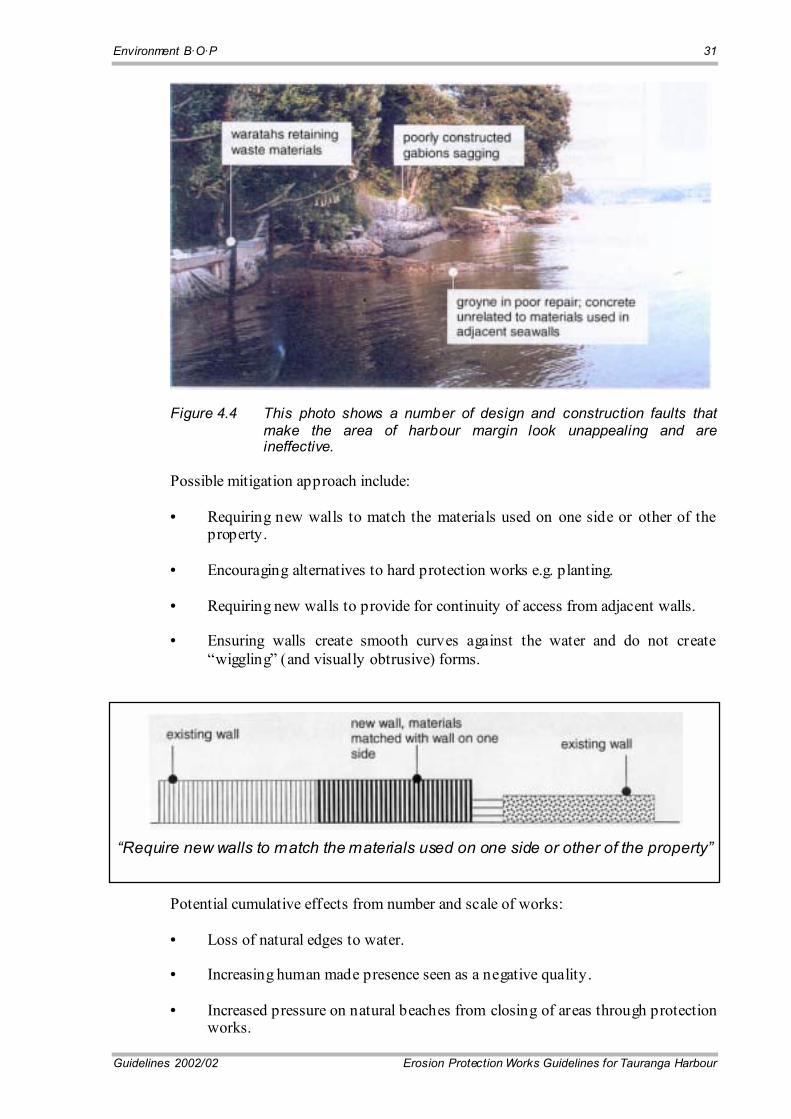
Figure 4.4 This photo shows a number of design and construction faults that make the area of harbour margin look unappealing and are ineffective.
Possible mitigation approach include:
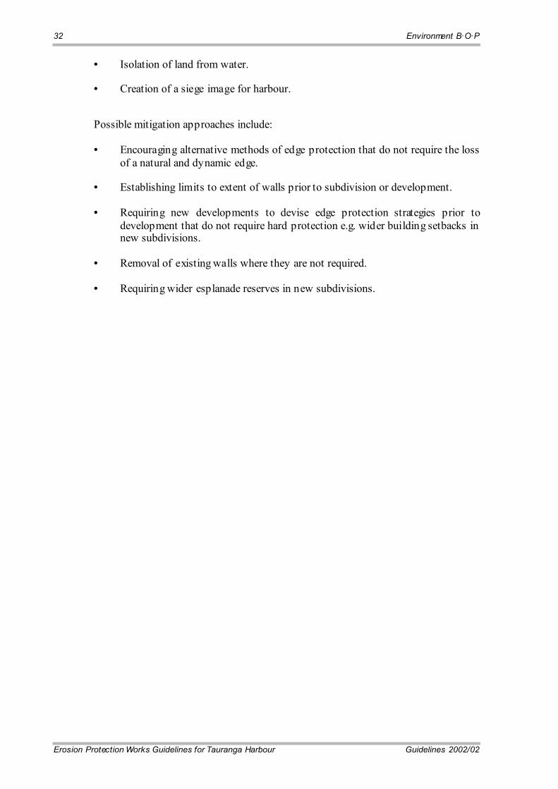
• Requiring new walls to match the materials used on one side or other of the property.
• Encouraging alternatives to hard protection works e.g. planting.
• Requiring new walls to provide for continuity of access from adjacent walls.
• Ensuring walls create smooth curves against the water and do not create �wiggling� (and visually obtrusive) forms.
�Require new walls to match the materials used on one side or other of the property�
Potential cumulative effects from number and scale of works:
• Loss of natural edges to water.
• Increasing human made presence seen as a negative quality.
• Increased pressure on natural beaches from closing of areas through protection works.
32 Environment B·O·P
Erosion Protection Works Guidelines for Tauranga Harbour Guidelines 2002/02
• Isolation of land from water.
• Creation of a siege image for harbour.
Possible mitigation approaches include:
• Encouraging alternative methods of edge protection that do not require the loss of a natural and dynamic edge.
• Establishing limits to extent of walls prior to subdivision or development.
• Requiring new developments to devise edge protection strategies prior to development that do not require hard protection e.g. wider building setbacks in new subdivisions.
• Removal of existing walls where they are not required.
• Requiring wider esplanade reserves in new subdivisions.

33
Guidelines 2002/02 Erosion Protection Works Guidelines for Tauranga Harbour
Part II: Design and Construction for Protection Works
Part II outlines the various �soft options� and gives a procedure for the design of six standard �hard� protection works. Materials and costs are also included where possible. These designs will not automatically gain resource consent but do give the user options from which to choose. Site-specific factors will be taken into account during the resource consent process.

35
Guidelines 2002/02 Erosion Protection Works Guidelines for Tauranga Harbour
Chapter 5: Recommended Procedures for Using Design Guidelines
At present Environment B·O·P, Western Bay of Plenty District Council and Tauranga District Council are together undertaking further research on appropriate types of soft protection works suitable for the Tauranga Harbour and Estuary environment. Contact any of the Council�s for further information.
5.1 Design
5.1.1 Preliminary consideration � the use of soft (minimum intervention) approaches
Before any choice of a hard option is made as part of a proposed solution to a coastal erosion problem, the possibility of a soft or semi soft solution to the problem must first have been considered and exhausted.
The following sequence of items should be checked:
• Confirm the existence of a coastal erosion problem.
• Be clear about the nature of the coastal processes acting at the site and in the surrounding area and their impact.
• Evaluate landscape amenity value.
• Evaluate all possible soft options, including the �do-nothing� option. Due to the inevitable and continuing nature of the basic cause (wave borne energy) of the erosion process, and the increasing likelihood of sea level rise, there is a real risk that costly hard solutions may prove ineffective before the end of their design life.
• The cost of sacrificing land, or purchasing more land, at this point in time should therefore also be taken into account, to check that it is not more economical than capital works.
5.1.2 Soft Structural Options
Soft options are intended to enhance and maintain the natural capacity of beaches, dunes and vegetation to absorb and disperse wave energy.
36 Environment B·O·P
Erosion Protection Works Guidelines for Tauranga Harbour Guidelines 2002/02
In most cases soft protection works are more consistent with recreational use and the natural character of beaches. These options reduce the risk of erosion by either accommodating or altering coastal processes and include the following:
• Revegetation.
• Beach nourishment.
• Beach scraping.
• Back beach reconstruction.
• Beach dewatering.
• Modification of the slope profile.
• Stopbank removal or breaching to allow saltwater inundation and reestablishment of saltmarsh.
These soft engineering methods aim to work with nature by manipulating natural systems that can adjust to the energy of waves and tides to good effect and have the potential for achieving economies whilst minimising the impact of traditional engineering structures.
An appropriate soft protection method has the following requirements:
• A suitable scale of investigation to understand the processes in the dynamic natural system that the protection is being placed.
• A design that incorporates the variability of the natural processes. This includes man made changes in the environment as well as the larger scale effects of long-term sea level adjustment and other aspects of climate change.
• Ongoing maintenance, if required for the option to remain effective. Maintenance requirements should be taken into account in cost/risk/benefit studies and the comparison of options.
5.1.3 �Semi-Soft� Structural Options (or �Combined� Options)
Semi-soft structural options are classed as those with a combination of the above soft options and a structural component. The structural component is generally designed to be of a temporary nature and able to be easily removed should the works result in adverse effects. Semi-soft structural options include the following:
• Headlands, nearshore breakwaters and groynes constructed of sand-filled geotextile (sand sausage).
• Timber groynes or grouted sandbag groynes.
• Perched beaches.
5.1.4 Selection Criteria for Choice of Protection Type

Environment B·O·P 37
Guidelines 2002/02 Erosion Protection Works Guidelines for Tauranga Harbour
• Evaluate the local wave climate (Figure 2). Generally soft options are only suitable for low energy environments.
• Consider the suitability of each option as listed in Section 2.3.3.
• Take into account the visual setting of the coastline. The appropriateness of the proposal should be in accordance with Section 3.1 to 3.7.
• Evaluate the types and density of any vegetation that may be present in the vicinity.
• Determine the beach or foreshore material (e.g. sand, mud etc) and the back beach nature and materials (e.g. dune, bank, cliff etc).
• Evaluate the variability of the natural processes acting in the area.
• Take into account the type and appearance of any existing structures adjoining the area or in the vicinity.
• Evaluate long-term maintenance requirements.
5.1.5 Design Methodology
Having selected a preferred option from the various possibilities of �soft� or combination options, the design methodology may need to include the following items. Whether these need to be included depends on the type of protection method chosen.
(a) Complete a photographic record of the site and the site surrounds.
(b) Site survey. This should include the foreshore (20m minimum), out from the chosen position of the bottom of the bank, also the approximate position of the MHWS mark, MLWS mark, bottom and toe of the eroding bank and the back shore area. In some cases, the bottom profile of the adjacent underwater areas may also be required. All existing structures and relevant features should be identified (e.g. stormwater outfalls, road edges, trees etc.) Plan and cross-sectional surveys should be undertaken, as they will be required for resource consent application as well as for design. All surveys should be to Moturiki Datum.
(c) Geotechnical Investigation. For nourishment and dredging options, particle size grading of the beach material will be required. For semi-soft or combined options, scala penetrometer testing will be required. Testing should be undertaken along the proposed seawall foundation line at intervals of no greater than 10m and extend to 3m in depth or until 10 blows per 50mm is achieved. For a property with a 20m shoreline frontage a minimum of three sites should be investigated, i.e. at 10m centres along the shoreline. This should be carried out by a geotechnical engineer or an engineering geologist.
(d) Design Water Level. This is fully discussed in paragraph 5.2(a) of these guidelines.
5.1.6 Hard Structural Options
38 Environment B·O·P
Erosion Protection Works Guidelines for Tauranga Harbour Guidelines 2002/02
If a hard solution is inevitable, the next step is to ascertain if a standard design could be used. To check this, the Energy Environment Classification should be determined from Figure 2, and the �disqualifying factors� (paragraph 2.2.4) should be checked.
If a standard solution is then still an option, depending on the Energy Environment Classification (Low, Medium or High), one or more of the six generic designs may be appropriate.
The designs that are still available at this point should also be compared cost-wise (after a rough design to enable cost estimation). The costing should be done on the basis of an assumed maximum design life of 50 years, or the estimated actual design life (see table 2.2.6), whichever is the lesser, and an annual cost should be calculated assuming a full writing off of the costs over the applicable design life.
5.1.7 Selection Criteria for Choice of Seawall Type
• Consider the suitability of each option as discussed in paragraph 2.2.6.
• Take into account the type and appearance of any existing structures adjoining the proposed new structure or existing in the vicinity.
• The proposed structure should be designed for the local wave climate (Figure 2).
• The proposed design life according to circumstances at time of choice must be taken into account.
• The choice being made should be consistent with the existing visual setting, or should improve it. The appropriateness of the proposal should be in accordance with sections 3.1 to 3.7.
• Take into account the local geomorphology, including the height and nature of the bank that is to be protected.
• Low bank and/or back shore level.
An important parameter in the design of the various seawall options is the minimum crest height above the design water level (hc). In some cases the minimum design crest level cannot be achieved because the top of the bank and the back shore area is lower than the minimum crest level. In this case, the crest of the seawall or revetment should be set to the �top of bank� level, and the inherent limitation recognised with regard to overtopping and flooding. Structural stability of the erosion protection can be provided by the use of a scour/overtopping apron comprising rock rip-rap, to landward of the seawall. However, access by the public should be provided for where practical. Additional protection will be achieved by a recommended 3m wide vegetation zone.
Environment B·O·P 39
Guidelines 2002/02 Erosion Protection Works Guidelines for Tauranga Harbour
5.1.8 Design Methodology
Having selected a preferred option the following methodology will determine the corresponding design dimensions and sizing.
• Site Survey
As set out in 5.1.5(b)
• Geotechnical Investigation
As set out in 5.1.5(c)
• Design Water Level
This is obtained from Figure 3 as fully discussed in paragraph 5.2(a).
• Determination of Design Limitation Parameters
Determine scala penetrometer results as above, backshore slope, hs, hc ht and hw as discussed in paragraph 5.2.
• Consistency with Limitations
Check if the proposal is consistent with paragraph 2.2.4. If not then a site-specific design will be required.
• Design Option
Proceed to design the chosen option according to the procedures set out in Chapters 6, 7, 8, 9, 10 or 11 and the corresponding drawing provided and the notes and specifications thereon.
5.2 Site Specific Considerations
(a) Design Water Level (DWL)
The Design Water Level (referred to by Tonkin and Taylor as the Inundation Level and the Extreme Still Water Level) is necessary for the design of each of the first four options listed in Table 2.2.6. The Design Water Level is dependent on the location of the proposed works and can be read from Figure 3. The various design parameters are illustrated in Figure 1.
(b) The Near Shore Depth (hs)
The value of hs is found by first determining a point 15m seawards, (perpendicular to the coastline) from the approximate position where the toe of the proposed structure will be. At this point (15m from the toe) the nearshore depth is measured as the vertical distance between the seabed and the Design Water Level as obtained previously.

40 Environment B·O·P
Erosion Protection Works Guidelines for Tauranga Harbour Guidelines 2002/02
(c) Estimated Depth of Scour (ds)
This depth is read off from the Tables given on each of the generic designs (Figures 4, 5 6, 7 and 8) and depends on the measured value of hs and the energy zone governing at the site. The depth ds is measured vertically downwards from the existing beach level at the point considered to be the position of the toe. The engineer doing the design has a discretion in deciding the point (or level) from which ds is measured down.
(d) Estimated Crest Level (hc)
This is the estimated height of the crest of the wall above the design water level, (DWL) (already known). It also depends on the value of hs as measured, and the governing energy zone at the location, and is read from the tables on the generic designs (Figures 4 to 8) (as for ds). If hc is found to yield a level higher than the existing ground level at the top of the wall being designed, then the wall must be finished to the existing ground level and hc is set equal to the vertical distance between that ground level and the design water level.
(e) Height of the Wall above the Toe (ht)
This value is found by measuring vertically upwards, from the same level from which ds is measured downwards (see paragraph (c)), up to the estimated crest level (hc) (as explained in paragraph (d))
(f) The Height of the Wall (hw)
This is defined as hw = ht + ds Having defined the meaning of Design Water Level, hs, ds, hc, ht, and hw, the design of each of the standard options is done as set out in paragraphs 7.1, 8.1, 9.1, 10.1 and 11.1.
5.3 General Construction Procedures
The following general construction procedures shall be followed in the case of all six types of seawall:
• All resource consents are to be obtained before construction starts.
• Access to site should be in agreement with private land owners (if applicable), the appropriate District Council and Environment B·O·P.
• Use of vehicles on the beach foreshore should be avoided as much as possible.
• If vehicles are to be used on the beach/foreshore area they should keep within a 15m corridor of the work area. All soft muddy foreshore areas of marine vegetation should be avoided, or where muddy foreshore access cannot be avoided, swamp mats or other means to minimise disturbance to the foreshore should be used.
Environment B·O·P 41
Guidelines 2002/02 Erosion Protection Works Guidelines for Tauranga Harbour
• If permanent damage to the foreshore or marine vegetation occurs the damage shall be reported to Environment B·O·P and shall be remediated to the satisfaction of Environment B·O·P. Note: unauthorised damage may result in enforcement action being taken against the consent holder.
• Prior to work commencing all equipment should be checked to ensure it is in good operating condition. Equipment not in good condition or prone to oil or fuel leaks shall not be used.
• Work at the site shall be undertaken when the tide is below MSL or when there is sufficient dry beach to maintain the work corridor.
• The timing of the works should be planned to minimise inconvenience to the public. Works should be avoided during weekends and public holidays.
• Clearly mark and place safety fencing around construction areas and stockpile areas.
• Ensure stockpiles pose no hazard to public safety and allow public access along footpaths and walkways.
• Stockpiling of construction materials shall be outside the coastal marine area. If this is not possible, construction material should be stored above MHWS so that it does not interfere with the sediment transport process.
5.4 Specification of Material
This is largely covered in the notes which appear on the individual drawings, numbered Figures 4 to 9.
In addition, the following materials specifications should be adhered to:
• Rock used shall have a quality of AA, AB, AC, BA, BB or CC when tested according to NZS 3111 section 15: �Method of Determining Weathering Resistance of Coarse Aggregate�.
• Rock density must be tested before use and shall in no circumstance have a density of less than 2500kg/m3.
• For the case of grouted seawalls the facing rock shall range between 0.1 and 0.5m in diameter and where practicable be of appropriate colour to blend with the surroundings.
• For the case of grouted seawalls the grout shall be suitably coloured to match the rock colour (Bayferrox or similar).
• Geotextile shall be of high quality (needle punch or similar). See specifications on each individual drawing.
• Timber shall be treated to a level required for long-term exposure to marine environments. H6 marine treated timber required.
42 Environment B·O·P
Erosion Protection Works Guidelines for Tauranga Harbour Guidelines 2002/02
• All nails and mesh used in gabions shall be corrosion resistant and able to withstand long-term marine exposure.

43
Guidelines 2002/02 Erosion Protection Works Guidelines for Tauranga Harbour
Chapter 6: Soft Options
6.1 Revegetation
For coastal protection on low energy shores, vegetation can provide a highly cost-effective contribution to coastal protection, providing vegetation is used in the right place at the right time and well-maintained.
Pohutukawa, karo, ngaio, taupata, saltmarsh ribbonwood, cabbage tree, flax, sea rush and jointed rush were investigated for erosion control potential in the estuaries of coastal North Island regions. A summary of the results is in Table 6.1.1.
6.1.1 Salt Marsh
Plants suitable for revegetation in the Tauranga Harbour include the following:
• Juncus maritimus (wiwi or sea rush)
• Schoenoplectus pungens (club rush)
• Leptocarpus similis (oioi)
• Avicennia resinifera (mangrove)
Planting vegetation that occurs naturally in the area, or in a similar environment, will increase the natural regeneration process and provide a greater plant density.
Care should be taken that weed species are not propagated inadvertently.
In designing a planting scheme, Environment B·O·P and the Department of Conservation are able to provide advice on the most suitable plants for the environment.

44 Environment B·O·P
Erosion Protection Works Guidelines for Tauranga Harbour Guidelines 2002/02
Table 6.1.1 Plant Characteristics
Species Growth Habit
Root Morpholo
gy
Propagation
Erosion Control
Site Requirements
Ecological Value
Cultural Value
Amenity Value
Pohutukawa Spreading Heartroot, dense
Seed, cuttings
Shallow, deep
Colonising, f ertiliser
High High High
Karo Tree Heartroot, spreading
Seed, cuttings
Shallow, deep
Colonising Medium High Medium
Ngaio Tree, shrub
Heartroot, dense
Seed, cuttings
Surf ace, shallow, deep
Topsoil Unknown High Medium
Taupata Shrub Heartroot, dense
Seed, cuttings
Surf ace, shallow, deep
Topsoil Medium High Medium
Saltmarsh Ribbonwood
Shrub Heartroot, f ibrous
Seed, cuttings
Wav elap, tidal, surf ace
Topsoil Medium Medium Medium
Cabbage Tree
Tree Taproot, dense sinkers
Seed, stem div isions
Deep, wind, shallow
Topsoil High High High
Flax Shrub Fibrous, strong
Seed, div isions
Surf icial, shallow
Colonising, f ertiliser
High High High
Sea Rush Grass Fibrous, strong
Div isions Surf icial, tidal, wav elap
Wet substrate Medium Medium Medium
Jointed Rush Grass Fibrous, strong
Div isions Surf icial, tidal, wav elap
Stable, damp soil
Medium Medium High
Results from salt marsh revegetation research suggest that:
• For revegetation of sheltered mudflats using Juncus maritimus, large or medium clumps may be transplanted.
• Where large-scale clumps are transplanted and resources are limited, medium sized clumps could be planted at wide spacing.
• Where rapid revegetation of the mudflats is desirable, the preferred option is to plant large transplants at close spacing.
• Where restoration of previously vegetated sites is considered, the relative proportions of species that once existed or are present in nearby natural areas should be used to determine appropriate species mix and planting pattern.
• There appears to be little difference between growth and survival rates between plantings protected with mesh or sand bags versus unprotected plantings.
• Timing of planting appears to be crucial to survival, but further research is required to determine the optimum.
• When planting seedlings (Juncus maritimus and Leptocarpus similis) in root trainers and then planting below MHWS (i.e. into saline areas), the medium these plants are grown in may be important for plant survival.
For areas where mangroves (Avicennia resinifera) are to be propagated and established (along eroding areas of harbour coastline where they are already present), the following points are considered important:
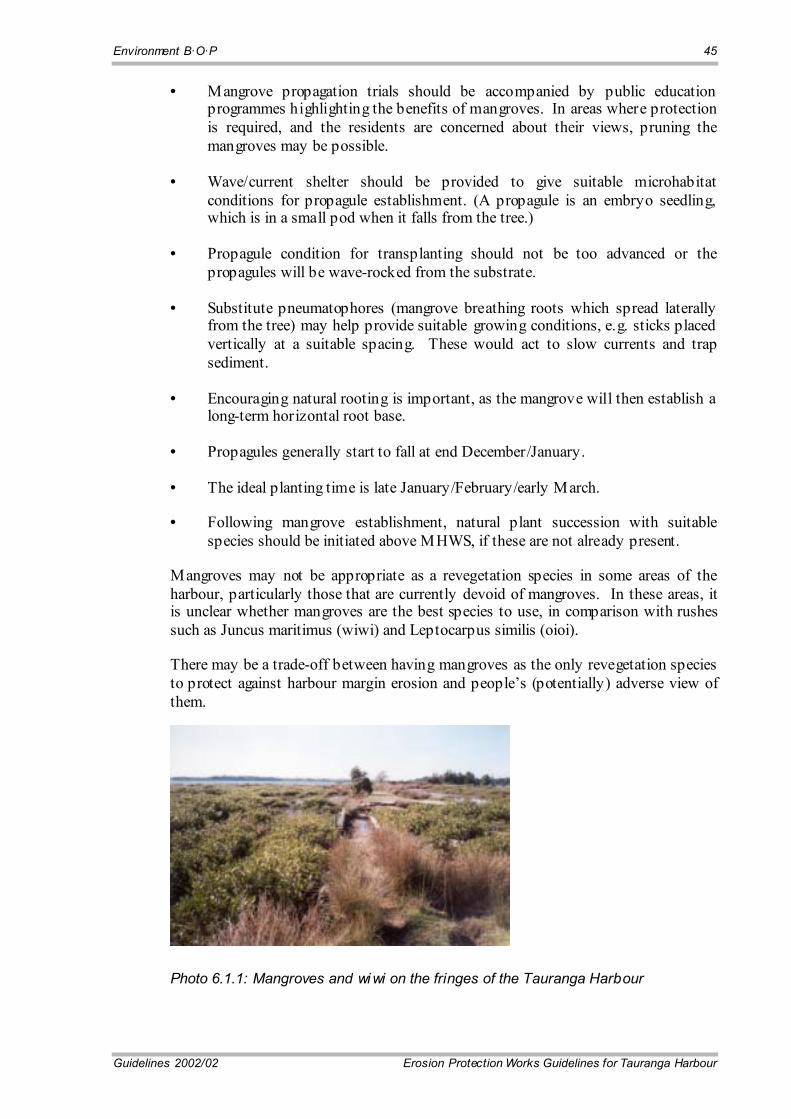
Environment B·O·P 45
Guidelines 2002/02 Erosion Protection Works Guidelines for Tauranga Harbour
• Mangrove propagation trials should be accompanied by public education programmes highlighting the benefits of mangroves. In areas where protection is required, and the residents are concerned about their views, pruning the mangroves may be possible.
• Wave/current shelter should be provided to give suitable microhabitat conditions for propagule establishment. (A propagule is an embryo seedling, which is in a small pod when it falls from the tree.)
• Propagule condition for transplanting should not be too advanced or the propagules will be wave-rocked from the substrate.
• Substitute pneumatophores (mangrove breathing roots which spread laterally from the tree) may help provide suitable growing conditions, e.g. sticks placed vertically at a suitable spacing. These would act to slow currents and trap sediment.
• Encouraging natural rooting is important, as the mangrove will then establish a long-term horizontal root base.
• Propagules generally start to fall at end December/January.
• The ideal planting time is late January/February/early March.
• Following mangrove establishment, natural plant succession with suitable species should be initiated above MHWS, if these are not already present.
Mangroves may not be appropriate as a revegetation species in some areas of the harbour, particularly those that are currently devoid of mangroves. In these areas, it is unclear whether mangroves are the best species to use, in comparison with rushes such as Juncus maritimus (wiwi) and Leptocarpus similis (oioi).
There may be a trade-off between having mangroves as the only revegetation species to protect against harbour margin erosion and people�s (potentially) adverse view of them.
Photo 6.1.1: Mangroves and wi wi on the fringes of the Tauranga Harbour
46 Environment B·O·P
Erosion Protection Works Guidelines for Tauranga Harbour Guidelines 2002/02
6.2 Beach Nourishment
Artificial beach nourishment (or beach fill) is based on the idea that sand is brought towards the coastline from elsewhere, with the intention that it may erode at the beach, protecting the original coastline.
The nourishment requires repeating at more-or-less regular intervals, depending on the number of storms occurring during the intervals.
Design of a beach nourishment should be carried out by a suitably qualified coastal engineer.
The main factors to consider when designing a beach nourishment include:
• The volume of sand required.
• The design beach profile.
• Where to place the nourishment within the beach profile.
• Sediment size of the nourishment sand.
• Calculation of likely frequency of renourishment.
• Nourishment and maintenance (renourishment) costs for different locations.
Design methods generally assume that extensive data collection has been carried out on shoreline movement at the potential nourishment site, e.g. the "Dutch Design Method", which has been used in many European countries, has the following steps:
• Perform coastal measurements (preferably for at least 10 years).
• Calculate the "loss of sand" in m3/year per coastal section.
• Add 40 % loss.
• Multiply this quantity with a convenient lifetime (for example five years).
• Put this quantity somewhere on the beach between the low-water-minus-1-metre line and the dune foot (or upper limit of the swash zone).
Where extensive and detailed historical records of shoreline movement is not available for eroding areas, the nourishment design will have greater uncertainty. This may be dealt with in the beach nourishment design process by using the data that is available and monitoring the subsequent post-nourishment shoreline movement.
The site (including adjacent areas) should be monitored for a time before the nourishment and then changes monitored after nourishment. Flexibility in the initial estimates of the renourishment period will be required, as the lack of information will make this difficult to estimate.

Environment B·O·P 47
Guidelines 2002/02 Erosion Protection Works Guidelines for Tauranga Harbour
Beach nourishment has been successfully undertaken around Tauranga Harbour at Pilot Bay, Sulphur Point and Whareroa Marae beaches.
Photo 6.2.2. Sulphur Point (northern-end beach) after recent nourishment with 200m3 of sand in December 2001. Due to site conditions nourishment here is required every 1-2 years.
6.2.1 Cost Estimate
The indicative cost for beach nourishment including sand supply, cartage and placement varies from $15 per cubic metre to around $30 per cubic metre, depending on the cost of the sand, transport and placement costs. The width of the beach being nourished or re-created will increase these indicative costs. For example a 10m wide beach will have a cost range of $150 to $300 per linear metre if a 1m deep beach is to be formed. Actual costs for the works will also vary according to local site conditions and beach form, dictating the amount of sand required. Additional costs for the consent process, design investigations, and supervision (if required) should be added.
A well-designed beach nourishment may have a life of 8-12 years, with additional cost in maintaining the beach form beyond its expected life.
6.3 Back Beach Reconstruction
Reforming dunes into an area of sand with no major hummocks or undulations that would interrupt wind flow and cause the wind to concentrate. May involve filling of small blowouts, or on a larger scale, the reconstruction of hundreds of metres of dune.
48 Environment B·O·P
Erosion Protection Works Guidelines for Tauranga Harbour Guidelines 2002/02
Reconstruction may involve:
• Reshaping existing dunes.
• Placing additional sand.
• Installation of dune fences.
• Planting vegetation to trap existing sand using appropriate species of grasses, shrubs and trees on the foredunes and backdunes.
• Providing access ways, fences and signs to further reduce dune damage.
Dune and back beach reconstruction may be suitable for use in the Tauranga Harbour, depending on the local morphology.
Advice on dune and back beach reconstruction should be sought from a qualified coastal engineer.
6.4 Beach Dewatering
Beach dewatering, or beach drainage involves the localised lowering of the water table beneath and parallel to the beach face to cause accretion of sand above the installed drainage system.
The beach dewatering system is based on the following approach:
• Lowering the water table in sand (a granular soil) will improve the stability and eliminate the tendency for the grains to move (i.e., �well-pointing�).
• Lowering the water table in sand eliminates buoyancy factors and reduces the lubricating effect between the grains, restoring the frictional characteristics of the sand.
• Percolation of 'swash water' into the beach means less backwash energy, which encourages suspended sand to settle out on the beach face.
Sand deposition from beach drainage occurs through backwash reduction, seepage reduction and liquefaction reduction.
Beach dewatering is achieved by installing a drainage system in the beach that lowers the beach face water table (as shown in Diagram 6.4).
Collection pipes are buried in the beach parallel to the coastline to create an unsaturated zone beneath the beach face.
This unsaturated zone is achieved through intercepting the flow of swash, tidal and inland ground water by draining away by gravity to a collector sump and pumping station.
The sump and buried pumping station are located at the back of the beach, where they are not readily visible.
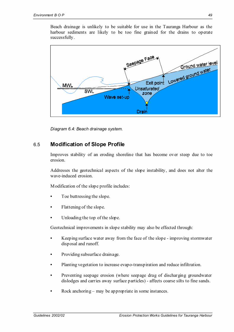
Environment B·O·P 49
Guidelines 2002/02 Erosion Protection Works Guidelines for Tauranga Harbour
Beach drainage is unlikely to be suitable for use in the Tauranga Harbour as the harbour sediments are likely to be too fine grained for the drains to operate successfully.
Diagram 6.4: Beach drainage system.
6.5 Modification of Slope Profile
Improves stability of an eroding shoreline that has become over steep due to toe erosion.
Addresses the geotechnical aspects of the slope instability, and does not alter the wave-induced erosion.
Modification of the slope profile includes:
• Toe buttressing the slope.
• Flattening of the slope.
• Unloading the top of the slope.
Geotechnical improvements in slope stability may also be effected through:
• Keeping surface water away from the face of the slope - improving stormwater disposal and runoff.
• Providing subsurface drainage.
• Planting vegetation to increase evapo-transpiration and reduce infiltration.
• Preventing seepage erosion (where seepage drag of discharging groundwater dislodges and carries away surface particles) - affects coarse silts to fine sands.
• Rock anchoring � may be appropriate in some instances.
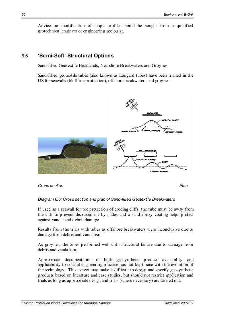
50 Environment B·O·P
Erosion Protection Works Guidelines for Tauranga Harbour Guidelines 2002/02
Advice on modification of slope profile should be sought from a qualified geotechnical engineer or engineering geologist.
6.6 �Semi-Soft� Structural Options
Sand-filled Geotextile Headlands, Nearshore Breakwaters and Groynes
Sand-filled geotextile tubes (also known as Longard tubes) have been trialled in the US for seawalls (bluff toe protection), offshore breakwaters and groynes.
Cross section Plan
Diagram 6.6: Cross section and plan of Sand-filled Geotextile Breakwaters
If used as a seawall for toe protection of eroding cliffs, the tube must be away from the cliff to prevent displacement by slides and a sand-epoxy coating helps protect against vandal and debris damage.
Results from the trials with tubes as offshore breakwaters were inconclusive due to damage from debris and vandalism.
As groynes, the tubes performed well until structural failure due to damage from debris and vandalism.
Appropriate documentation of both geosynthetic product availability and applicability to coastal engineering practice has not kept pace with the evolution of the technology. This aspect may make it difficult to design and specify geosynthetic products based on literature and case studies, but should not restrict application and trials as long as appropriate design and trials (where necessary) are carried out.
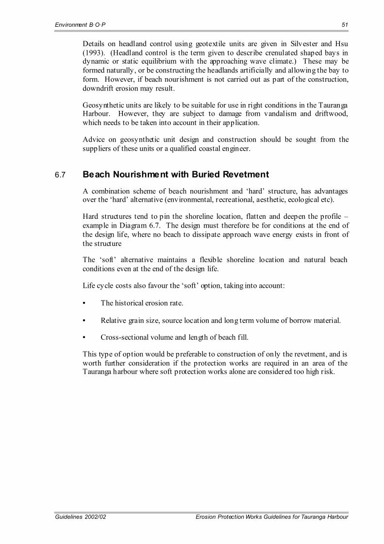
Environment B·O·P 51
Guidelines 2002/02 Erosion Protection Works Guidelines for Tauranga Harbour
Details on headland control using geotextile units are given in Silvester and Hsu (1993). (Headland control is the term given to describe crenulated shaped bays in dynamic or static equilibrium with the approaching wave climate.) These may be formed naturally, or be constructing the headlands artificially and allowing the bay to form. However, if beach nourishment is not carried out as part of the construction, downdrift erosion may result.
Geosynthetic units are likely to be suitable for use in right conditions in the Tauranga Harbour. However, they are subject to damage from vandalism and driftwood, which needs to be taken into account in their application.
Advice on geosynthetic unit design and construction should be sought from the suppliers of these units or a qualified coastal engineer.
6.7 Beach Nourishment with Buried Revetment
A combination scheme of beach nourishment and �hard� structure, has advantages over the �hard� alternative (environmental, recreational, aesthetic, ecological etc).
Hard structures tend to pin the shoreline location, flatten and deepen the profile � example in Diagram 6.7. The design must therefore be for conditions at the end of the design life, where no beach to dissipate approach wave energy exists in front of the structure
The �soft� alternative maintains a flexible shoreline location and natural beach conditions even at the end of the design life.
Life cycle costs also favour the �soft� option, taking into account:
• The historical erosion rate.
• Relative grain size, source location and long term volume of borrow material.
• Cross-sectional volume and length of beach fill.
This type of option would be preferable to construction of only the revetment, and is worth further consideration if the protection works are required in an area of the Tauranga harbour where soft protection works alone are considered too high risk.
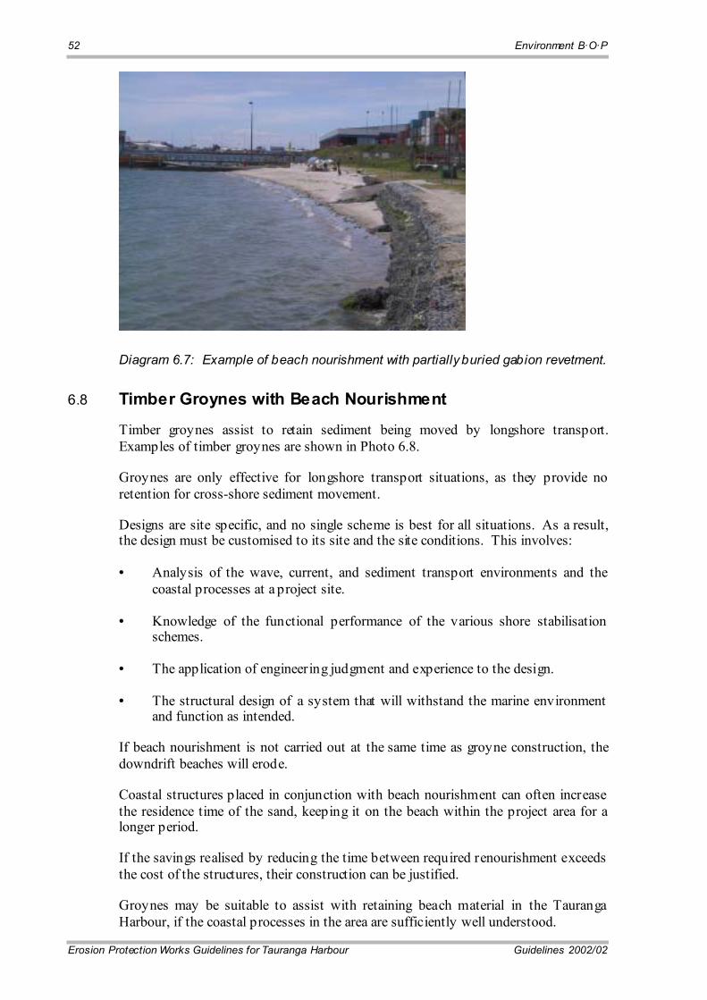
52 Environment B·O·P
Erosion Protection Works Guidelines for Tauranga Harbour Guidelines 2002/02
Diagram 6.7: Example of beach nourishment with partially buried gabion revetment.
6.8 Timber Groynes with Beach Nourishment
Timber groynes assist to retain sediment being moved by longshore transport. Examples of timber groynes are shown in Photo 6.8.
Groynes are only effective for longshore transport situations, as they provide no retention for cross-shore sediment movement.
Designs are site specific, and no single scheme is best for all situations. As a result, the design must be customised to its site and the site conditions. This involves:
• Analysis of the wave, current, and sediment transport environments and the coastal processes at a project site.
• Knowledge of the functional performance of the various shore stabilisation schemes.
• The application of engineering judgment and experience to the design.
• The structural design of a system that will withstand the marine environment and function as intended.
If beach nourishment is not carried out at the same time as groyne construction, the downdrift beaches will erode.
Coastal structures placed in conjunction with beach nourishment can often increase the residence time of the sand, keeping it on the beach within the project area for a longer period.
If the savings realised by reducing the time between required renourishment exceeds the cost of the structures, their construction can be justified.
Groynes may be suitable to assist with retaining beach material in the Tauranga Harbour, if the coastal processes in the area are sufficiently well understood.
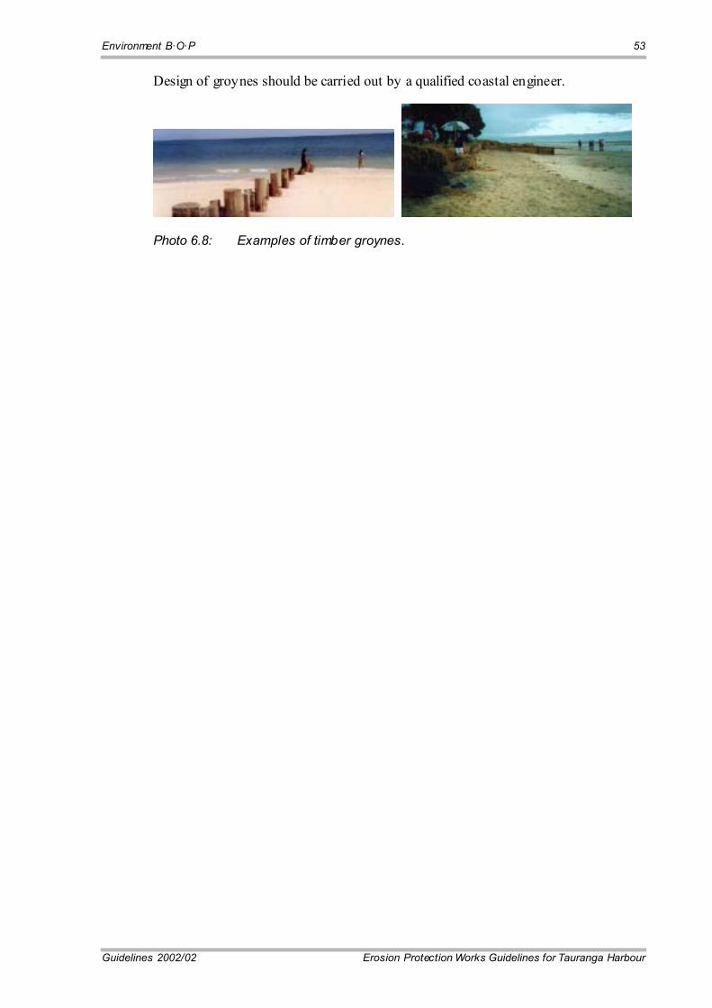
Environment B·O·P 53
Guidelines 2002/02 Erosion Protection Works Guidelines for Tauranga Harbour
Design of groynes should be carried out by a qualified coastal engineer.
Photo 6.8: Examples of timber groynes.

55
Guidelines 2002/02 Erosion Protection Works Guidelines for Tauranga Harbour
Chapter 7: Rip-rap Revetments
7.1 Design
Determine the value of hs and if hs > 2.0 m, then a site-specific assessment is needed.
If hs < 2.0 m; follow the design as presented in Figure 4 and respect the requirements as stated under �NOTES�.
With hs known and using the correct row in Table 2 on Figure 4 as determined by the value of hs, and the correct box for the governing wave energy zone, read off ds, D50 (armour layer), allowable grading for the armour layer, minimum thickness ta for the armour layer, D50 (filter layer), allowable grading for the filter layer, minimum thickness tf for the filter layer and Ls and hc.
By plotting a preliminary design to scale, or on squared paper on which a long section of the beach is also plotted, the position (level) from which ds must be measured downwards, and from which ht is to be measured upwards, is conveniently determined. Record the value of ht as per paragraph 5.2(e). Calculate hw = ht + ds, but take note that according to note number 7 on Figure 4, if this shows a wall height higher than the existing ground level at top of bank, then finish the wall to a height D50(A) above existing ground level. Read D50(A) from Table 2 Figure 4. Using these values together with the specifications supplied on Figure 4 the design may then be completed.
7.2 Specific Construction Procedure
The following specific construction procedure should be followed in the case of a Rip-rap wall:
• Get resource consent before start of construction.
• The alignment of the seawall should follow the curvature of the existing bank (as far as practicable).
• The portion of bank where the revetment will be situated should be trimmed so that a 1(v):2(h) slope can be achieved. It is permitted to place and compact excavated fill at the toe of the bank prior to the placement of the geofabric and filter layer as long as the minimum filter layer depth is achieved. Compaction shall be in accordance with TNZ F/1 (1997) with the minimum number of passes as given by TNZF/1 Notes (1997). Alternatively, the filter layer material may be used as fill as long as the minimum filter layer depth is achieved.
56 Environment B·O·P
Erosion Protection Works Guidelines for Tauranga Harbour Guidelines 2002/02
• Prepare foundations. Clear and stockpile beach sediment (sand) for reuse or remove from site. Excavated non sandy foundation material shall be immediately removed from the coastal marine area and appropriate silt control measures installed, such as placing weighted geofabric over the exposed bank and footing.
• Quarried rock to be placed at the site, shall be transported and handled in such a manner as to minimise segregation of the rock.
• Filter layer material shall be placed in a manner so that the geofabric is not punctured or torn, and a minimum lap of 0.3m is provided with any adjacent sheet of geofabric.
• Seawall returns at either end of the structure shall extend a minimum of 0.9m (low energy case), 1.6m (medium energy case) or 2.2m (high energy case) back from the wall. If the proposed wall is extending an existing wall, the wall shall be adequately joined, e.g. by keying into the existing wall.
• Armour layer material shall be placed carefully to minimise disturbance of the filter material and to avoid damage to existing structures such as pipelines. Placement should be in a manner to minimise the segregation of the rock grading and to ensure the specified dimensions. Use of rock trays is permitted.
• The armour material shall be placed to ensure the larger rock fragments are uniformly distributed and the smaller rock fragments serve to fill spaces between the larger rock fragments in such a manner that the resulting structure will be well keyed, densely packed and to the specified dimensions. Hand placing will be required only to the extent necessary to secure results specified above.
• After works complete remove all excess construction materials off site, groom disturbed beach/foreshore/reserve areas, to the satisfaction of Environment B·O·P and the appropriate District Council.
• Maintenance may be required following significant storm events to maintain the functionality of the revetment. Maintenance should also include monitoring of the surrounding shoreline and areas that are eroding, particularly at the ends of the revetment.
The construction of a revetment could possibly reduce public access to the foreshore over the revetment. Consideration of access issues should be given in the consent application.
7.3 Cost Estimate The indicative cost for constructing a rip-rap revetment including site establishment, preparation of foundation and construction varies from around $600 per linear metre (low energy) through to around $1750 per linear metre (high energy). Actual costs for the works will vary according to local site conditions, height of the wall and ease of access. Additional costs for the consent process and design investigations (survey and geotechnical) and supervision (if required) should be added.

57
Guidelines 2002/02 Erosion Protection Works Guidelines for Tauranga Harbour
Chapter 8: Grouted Rock Wall
8.1 Design
Determine the value of hs and if hs > 2.0m then a site specific assessment is needed by a specialist coastal engineer.
If hs < 2.0 m; follow the design as presented in Figure 5 and respect the requirements as stated under �NOTES�.
With hs known and using the correct row in Table 1 on Figure 5 as determined by the value of hs, and the correct column for the governing wave energy zone, read off ds and hc. Determine ht as set out in paragraph 5.2(e). Then calculate hw = ht + ds.
Then use Table 2 on Figure 5 and for a firm or stiff soil as foundation, and for the appropriate value for hw, read off the acceptable minimum values of Wb and Wt as shown in the typical section on Figure 5. Note that for hw > 3.0 a site specific assessment is required.
Using these values together with the specifications supplied on Figure 5 the design may then be completed.
Note that a concrete bedding of at least 100mm below estimated scour depth must be provided.
8.2 Specific Construction Procedure
The following specific construction procedure should be followed in the case of a grouted seawall:
• The alignment of the seawall should follow the curvature of the existing bank.
• The position of the seawall should be at the toe of the existing bank or at a location to utilise the cut to fill of excavated material so that no material will be removed from the site. If cut material is not suitable for use as fill, or for placing below water level, then cut to waste is allowable.
• Seawall returns at either end of the structure shall extend a minimum of 0.9m (low energy case), 1.6m (medium energy) or 2.2m (high energy case) back from the wall. If the proposed wall is an extension of an existing wall, the wall shall be adequately joined.

58 Environment B·O·P
Erosion Protection Works Guidelines for Tauranga Harbour Guidelines 2002/02
• The seawall shall be installed prior to any bank trimming to reduce any possible siltation.
• Construct wall lengths at no more than 20m section lengths to minimise potential siltation effects.
• Prepare foundations. Clear and stockpile beach sediment (sand) for replacement back on the foreshore. Excavated foundation material (non sand) shall be immediately removed from the coastal marine area and appropriate silt control measures installed, such as placing weighted geofabric over the exposed bank and footing.
• Filter layer material will be placed in a manner so that the geofabric is not punctured or torn, and a minimum lap of 0.3m is provided with any adjacent sheet of geofabric.
• Quarried rock shall be suitably faced so that there are no sharp edges.
• Back fill material shall be placed in a manner so that the geofabric is not punctured or torn.
• The facing rock shall be placed to ensure that the larger rock fragments are uniformly distributed and the smaller rock fragments serve to fill spaces.
• A 50 mm grout free zone on the seaward face of the wall is to be maintained.
• After works complete remove all excess construction materials off site, groom disturbed beach/foreshore/reserve areas, both to the satisfaction of Environment B·O·P and the appropriate District Council.
• Monitoring and maintenance may be required following significant storm events to maintain the functionality of the seawall. The most common maintenance will be for initial settlement of backfill. Monitoring of the surrounding shoreline and areas that are eroding, particularly at the ends of the seawall, should be carried out.
The construction of a seawall could possibly reduce public access to the foreshore. Consideration of access issues should be given in the consent application.
8.3 Cost Estimate
The indicative cost for constructing a grouted rock seawall including site establishment, preparation of foundation and construction varies from around $1000 per linear metre (low energy) through to around $1950 per linear metre (high energy). Actual costs for the works will vary according to local site conditions, height of the wall and ease of access. Additional costs for the consent process and design investigations (survey and geotechnical) and supervision (if required) should be added.
59
Guidelines 2002/02 Erosion Protection Works Guidelines for Tauranga Harbour
Chapter 9: Timber Seawalls
9.1 Design
Determine the value of hs and if hs > 2.0m then a site specific assessment is needed by a specialist coastal engineer.
If hs < 2.0 m; follow the design as presented in Figure 6 and respect the requirements as stated under �NOTES�.
With hs known and using the correct row in Table 1 on Figure 6 as determined by the value of hs, and the correct column for the governing wave energy zone, read off ds and hc. Determine ht as set out in paragraph 5.2(e). Then calculate hw = ht + ds. Then use Table 2 on Figure 6 and for either a �Firm� or �Stiff� soil as foundation, and for the appropriate value for hw, read off the acceptable values for the Pile Embedment Depth, hem; the Pole Diameter and the Hole Diameter.
Using these values together with the specifications supplied on Figure 6, the design may be completed. Note that for hw > 3.0 a site specific assessment will be required. If the value of hc is such that the crest level of the wall will be higher than the existing ground level at the top of the bank, then the wall must be finished to the existing ground level.
Note: This design cannot be used in a high wave energy environment.
9.2 Specific Construction Procedure
The following specific construction procedure should be followed in the case of a Timber Seawall:
• The alignment of the seawall should follow the curvature of the existing bank (as far as practicable).
• The position of the seawall should be at the toe of the existing bank or at a location to utilise the cut to fill of excavated material so that no material will be removed from the site. If cut material is not suitable for use as fill, or for placing below water level, then cut to waste is allowable.
• Seawall returns at either end on the structure shall extend a minimum of 0.9m (low energy) or 1.6m (medium energy) back from the main seawall. If the proposed wall is extending an existing wall the wall shall be adequately joined.

60 Environment B·O·P
Erosion Protection Works Guidelines for Tauranga Harbour Guidelines 2002/02
• The seawall shall be installed prior to any bank trimming to reduce any possible siltation.
• Prepare foundations. Clear and stockpile beach sediment for reuse or remove from site. Excavated foundation material shall be immediately removed from the coastal marine area and appropriate silt control measures installed.
• Filter layer material must be placed in a manner so that the geofabric is not punctured or torn, and a minimum lap of 0.3m is provided with any adjacent sheet of geofabric.
• Back fill material shall be placed in a manner so that the geofabric is not punctured or torn.
• After works complete remove all excess construction materials off site, groom disturbed beach/foreshore/reserve areas, both to the satisfaction of Environment B·O·P and the appropriate District Council.
The following specifications must also be adhered to:
• The design of the timber wall shall be in accordance with the tables presented in Figure 6.
• Piles shall be concreted and be at the minimum depth as specified in Figure 6.
• Regular monitoring and maintenance should be undertaken following significant storm events to maintain the functionality of the seawall. Monitoring of the surrounding shoreline and areas that are eroding should be carried out at regular intervals, particularly at the ends of the seawall.
The construction of a seawall could possibly reduce public access to the foreshore. Consideration of access issues should be given in the consent application.
9.3 Cost Estimate
The indicative cost for constructing a timber seawall including site establishment, preparation of foundation and construction varies from around $850 per linear metre (low energy) through to around $1450 per linear metre (medium energy). Actual costs for the works will vary according to local site conditions, height of the wall and east of access. Additional costs for the consent process and design investigations (survey and geotechnical) and supervision (if required) should be added.

61
Guidelines 2002/02 Erosion Protection Works Guidelines for Tauranga Harbour
Chapter 10: Gabion Basket Revetment
10.1 Design
Determine the value of hs and if hs > 2.0m then a site specific assessment is needed by a specialist coastal engineer.
If hs < 2.0 m, follow the design as presented in Figure 7 and respect the requirements as stated under �NOTES�.
With hs known and using the correct row in Table 1 on Figure 7 as determined by the value of hs, and the correct column for the governing wave energy zone, read off ds and hc. Determine ht as set out in paragraph 5.2(e). Then calculate hw = ht + ds.
Then use Table 2 on Figure 7 and for either a �Firm� or a �Stiff� soil as foundation, and for the appropriate value for hw, read off the acceptable values for the width and height of the baskets to be used for the base layer and the second and third layer if applicable.
Using these values together with the specifications supplied on Figure 7, the design may be completed. Note that for hw > 3.0 a site specific assessment will be required. If the value of hc is such that the crest level of the wall will be higher than the existing ground level at top of bank, then the wall must be finished to the existing ground level. Note that a hardfill footing of minimum thickness of 100mm below scour depth is specified.
Note: This design cannot be used in a high wave energy environment.
10.2 Specific Construction Procedure
The following specific construction procedure should be followed in the case of a Gabion Seawall:
• The alignment of the seawall should follow the curvature of the existing bank (or as practicable).
• The position of the seawall should be at the toe of the existing bank or at a location to utilise the cut to fill of excavated material so that no material will be removed from the site. If cut material is not suitable for use as fill, or for placing below water level, then cut to waste is allowable.
62 Environment B·O·P
Erosion Protection Works Guidelines for Tauranga Harbour Guidelines 2002/02
• Seawall shall return a minimum of 1.0m (low energy) or 2.0m (medium energy) at either end on the structure. If the proposed wall is extending an existing wall the wall shall be adequately joined.
• The seawall shall be installed prior to any bank trimming to reduce any possible siltation.
• Prepare foundations. Clear and stockpile beach sediment (sand) for replacement on the foreshore. Excavated foundation material (non sandy material) shall be immediately removed from the coastal marine area and appropriate silt control measures installed. An engineer should approve the foundations before construction.
• Quarried rock shall be of suitable quality so that there are no sharp edges. River boulders are preferable due to their smooth edges.
• Filter layer material will be placed in a manner so that the geofabric is not punctured or torn, and a minimum lap of 0.3m is provided with any adjacent sheet of geofabric.
• Back fill material shall be placed in a manner so that the geofabric is not punctured or torn.
• After works complete remove all excess construction materials off site, groom disturbed beach/foreshore/reserve areas, to the satisfaction of Environment B·O·P and the appropriate District Council.
The following specifications must be adhered to, in addition to that specified in Figure 7:
• The design of the gabion basket wall shall be in accordance with the tables presented in Figure 7.
• Follow manufacturers detailed specification.
• Gabion baskets must be stretched longitudinally prior to filling to provide rigidity during construction. A hand operated one ton winch or similar should be used during the filling and tension process.
• Individual gabions must be laced together.
• Gabion baskets should be overfilled by about 50mm and the lid stretched down tight to compensate for settlement.
Regular monitoring and maintenance should be undertaken following significant storm events to maintain the functionality of the seawall. The most common maintenance will be repairs to the gabion mesh as a result of deterioration. Monitoring of the surrounding shoreline and areas that are eroding should be carried out regularly, particularly at the ends of the seawall.
The construction of a seawall could possibly reduce public access to the foreshore. Consideration of access issues should be raised in the consent application.

Environment B·O·P 63
Guidelines 2002/02 Erosion Protection Works Guidelines for Tauranga Harbour
10.3 Cost Estimate
The indicative cost for constructing a gabion basket seawall including site establishment, preparation of foundation and construction varies from around $700 per linear metre (low energy) through to around $1250 per linear metre (medium energy). Actual costs for the works will vary according to local site conditions, height of the wall and ease of access. Additional costs for the consent process and design investigations (survey and geotechnical) and supervision (if required) should be added.


65
Guidelines 2002/02 Erosion Protection Works Guidelines for Tauranga Harbour
Chapter 11: Gabion Mattress Revetment
11.1 Design
Determine the value of hs and if hs > 2.0m then a site specific assessment is needed by a specialist coastal engineer.
If hs < 2.0m, follow the design as presented in Figure 8 and respect the requirements as stated under �NOTES�.
With hs known and using the correct row in Table 1 on Figure 8 as determined by the value of hs, and the correct column for the governing wave energy zone, read off ds and hc. Determine ht as set out in paragraph 5.2(e). Then calculate hw = ht + ds.
Using these values together with the specifications supplied on Figure 8, the design may be completed. Note that for hw > 3.0 a site specific assessment will be required. If the value of hc is such that the crest level of the wall will be higher than the existing ground level at top of bank, then the wall must be finished to the existing ground level, using rock and geotextile as specified.
Note: This design cannot be used in a high wave energy environment.
11.2 Specific Construction Procedure
The following specific construction procedure should be followed in the case of a Gabion Seawall:
• The alignment of the seawall should follow the curvature of the existing bank (or as practicable).
• The position of the seawall should be at the toe of the existing bank or at a location to utilise the cut to fill of excavated material so that no material will be removed from the site. If cut material is not suitable for use as fill, or for placing below water level, then cut to waste is allowable.
• Seawall shall return a minimum of 1m (low energy) or 2.0m (medium energy) at either end on the structure. If the proposed wall is extending an existing wall the wall shall be adequately joined.
• The seawall shall be installed prior to any bank trimming to reduce any possible siltation.

66 Environment B·O·P
Erosion Protection Works Guidelines for Tauranga Harbour Guidelines 2002/02
• Prepare foundations. Clear and stockpile beach sediment (sand) for replacement on the foreshore. Excavated foundation material (non sandy material) shall be immediately removed from the coastal marine area and appropriate silt control measures installed. An engineer should approve the foundations before construction.
• Quarried rock shall be of suitable quality so that there are no sharp edges. River boulders are preferable due to their smooth edges.
• Filter layer material will be placed in a manner so that the geofabric is not punctured or torn, and a minimum lap of 0.3m is provided with any adjacent sheet of geofabric.
• Back fill material shall be placed in a manner so that the geofabric is not punctured or torn.
• After works complete remove all excess construction materials off site, groom disturbed beach/foreshore/reserve areas, to the satisfaction of Environment B·O·P and the appropriate District Council.
The following specifications must be adhered to, in addition to that specified in Figure 8:
• The design of the gabion mattress wall shall be in accordance with the tables presented in Figure 8.
• Follow manufacturers detailed specification.
Regular monitoring and maintenance should be undertaken following significant storm events to maintain the functionality of the seawall. The most common maintenance will be repairs to the gabion mesh as a result of deterioration. Monitoring of the surrounding shoreline and areas that are eroding should be carried out regularly, particularly at the ends of the seawall.
The construction of a seawall could possibly reduce public access to the foreshore. Consideration of access issues should be raised in the consent application.
11.3 Cost Estimate
The indicative cost for constructing a gabion mattress revetment including site establishment, preparation of foundation and construction varies from around $860 per linear metre (low energy) through to around $1450 per linear metre (medium energy). Actual costs for the works will vary according to local site conditions, height of the wall and ease of access. Additional costs for the consent process and design investigations (survey and geotechnical) and supervision (if required) should be added.

67
Guidelines 2002/02 Erosion Protection Works Guidelines for Tauranga Harbour
Chapter 12: Offshore Reef Breakwaters
12.1 Design
This option can only be used in a Low Wave Energy Environment, if used as a standard design. Offshore reef breakwaters may be used in Medium to High energy settings, but need site-specific design by coastal engineers.
The design is different and somewhat simpler than the preceding five options.
Use the design presented in generic form in Figure 9 and consider the requirements listed under �NOTES�.
The crest of the rocks should be as near as possible to 300mm above the level of the MHWS. MHWS is to be taken as RL 0.84m (Moturiki Datum) throughout the harbour, where low wave energy occurs.
Note that in this option the design water level as presented in Figure 3 is not used.
The average distance from the coastline should be 3m minimum and 6m maximum as shown.
12.2 Specific Construction Procedure
The following specific construction procedure should be followed in the case of a Breakwater:
• The alignment of the breakwaters should follow the curvature of the existing bank (or as practicable).
• The position of the inside edge of the breakwaters should be a maximum of 6m from the toe of the existing bank.
• Excavated material for the foundation of the breakwater shall be deposited in the lee of the breakwater to provide additional substrate for planting.
• Breakwater material shall be placed in a manner so that the geofabric is not punctured or torn.
• Planting should be undertaken following the construction of the breakwaters.

68 Environment B·O·P
Erosion Protection Works Guidelines for Tauranga Harbour Guidelines 2002/02
• After works complete remove all excess construction materials off site, groom disturbed beach/foreshore/reserve areas, both to the satisfaction of Environment B·O·P and the appropriate District Council.
The following specifications must be adhered to:
• The crest elevation should be 0.3m above MHWS (RL 0.84m).
• The design of the breakwaters shall be in accordance with Figure 9.
• The rock density for the works must be not less than 2500 kg/m3.
• The length to diameter ratio (l/d) of each rock shall not exceed 3.
• Planting should be immediately undertaken.
Regular monitoring and maintenance should be undertaken following significant storm events to maintain the functionality of the seawall. The most common maintenance item is replacing dead plants. Monitoring of the surrounding shoreline and areas that are eroding is recommended, particularly at the ends of the seawall.
Public access is not expected to be significantly affected with this option.
12.3 Cost Estimate
The indicative cost for constructing a rock reef for the low energy environment is approximately $250 per linear metre, including site establishment, preparation of foundation and construction. Actual costs for the works will vary according to local site conditions and ease of access. Additional costs for the consent process and design investigations (survey and geotechnical) and supervision (if required) should be added.

69
Guidelines 2002/02 Erosion Protection Works Guidelines for Tauranga Harbour
Chapter 13: Groynes and Other Options
13.1 Groynes
Although the possible use of groynes is mentioned in the Tonkin and Taylor report, no generic design is offered as it is considered that in all cases a site-specific assessment is required. In terms of landscape effects (See Chapter 3) these options are generally not appropriate.
The following is a list of some of the common deficiencies encountered with respect to groynes, as cited by Tonkin and Taylor.
• Inappropriate location of structures.
• Lack of understanding of the coastal processes operating at the site.
• Failure to consider lee side erosion effects.
• Inadequate design of structures that are founded on soft foundation material.
• Failure to use adequate rock of suitable size, grading and density.
• Failure to ensure that the voids between individual pieces of the armour layer are small enough to prevent washing out by waves of the underlying rock filter material.
• Inadequate design with respect to the appropriate height and length of the structures.
• Failure to use suitable geotextiles to limit the bypassing of sediment through the groyne structure.
• Some of the above deficiencies can be observed along Harbourside Drive on the Otumoetai Peninsula.
Although a site specific design will be required for the use of groyne structures, these guidelines present an opportunity to state certain considerations that will govern in the event that a groyne be decided upon as a solution. These are as follows:
• General construction procedures to be followed as per paragraph 5.3 of these guidelines.

70 Environment B·O·P
Erosion Protection Works Guidelines for Tauranga Harbour Guidelines 2002/02
• Specific construction procedure according to design, including:
• Rock density not less than 2,500 kg/m3.
• Length to diameter ratio of rocks not more than three to one.
• Issues of maintenance and public access to be addressed.
Groynes are not considered appropriate for visual/aesthetic reasons. However, they may work in the appropriate situation, but must be designed by a specialist coastal engineer.
13.2 Inappropriate Solutions
The following are considered inappropriate solutions to coastal erosion in Tauranga Harbour:
• Used tyres in any form.
• Beach scraping.
• Configuration dredging.
• Dumping car bodies/rubbish and broken concrete rubble.
71
Guidelines 2002/02 Erosion Protection Works Guidelines for Tauranga Harbour
Appendices Appendix I � Assessment of Materials from a Visual/Aesthetic Perspective
Appendix II � Sites of Special Sensitivity
Appendix III � Glossary

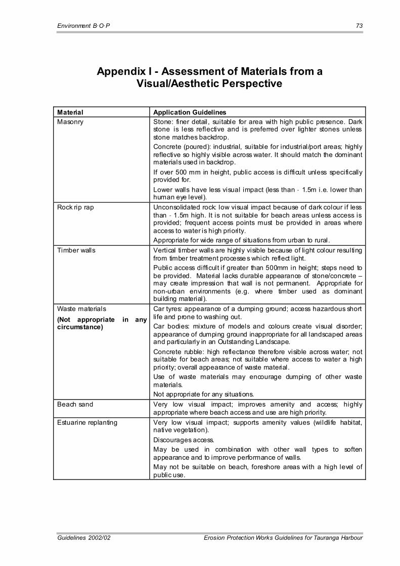
Environment B·O·P 73
Guidelines 2002/02 Erosion Protection Works Guidelines for Tauranga Harbour
Appendix I - Assessment of Materials from a Visual/Aesthetic Perspective
Material Application Guidelines Masonry Stone: finer detail, suitable for area with high public presence. Dark
stone is less reflective and is preferred over lighter stones unless stone matches backdrop. Concrete (poured): industrial, suitable for industrial/port areas; highly reflective so highly visible across water. It should match the dominant materials used in backdrop. If over 500 mm in height, public access is difficult unless specifically provided for. Lower walls have less visual impact (less than � 1.5m i.e. lower than human eye level).
Rock rip rap Unconsolidated rock: low visual impact because of dark colour if less than � 1.5m high. It is not suitable for beach areas unless access is provided; frequent access points must be provided in areas where access to water is high priority. Appropriate for wide range of situations from urban to rural.
Timber walls Vertical timber walls are highly visible because of light colour resulting from timber treatment processe s which reflect l ight. Public access difficult if greater than 500mm in height; steps need to be provided. Material lacks durable appearance of stone/concrete � may create impression that wall is not permanent. Appropriate for non-urban environments (e.g. where timber used as dominant building material).
Waste materials (Not appropriate in any circumstance)
Car tyres: appearance of a dumping ground; access hazardous short life and prone to washing out. Car bodies: mixture of models and colours create visual disorder; appearance of dumping ground inappropriate for all landscaped areas and particularly in an Outstanding Landscape. Concrete rubble: high reflectance therefore visible across water; not suitable for beach areas; not suitable where access to water a high priority; overall appearance of waste material. Use of waste materials may encourage dumping of other waste materials. Not appropriate for any situations.
Beach sand Very low visual impact; improves amenity and access; highly appropriate where beach access and use are high priority.
Estuarine replanting Very low visual impact; supports amenity values (wildlife habitat, native vegetation). Discourages access. May be used in combination with other wall types to soften appearance and to improve performance of walls. May not be suitable on beach, foreshore areas with a high level of public use.


Environment B·O·P 75
Guidelines 2002/02 Erosion Protection Works Guidelines for Tauranga Harbour
Appendix II � Sites of Special Sensitivity
Sites of special sensitivity, identified in terms of landscape and visual, amenity and public access values, include but are not limited to the sites listed below. The first table contains sites presently identified in the maps and schedules of the Proposed Bay of Plenty Regional Coastal Environment Plan. In the sites identified as Coastal Habitat Protection Zone (CHPZ), construction of protection works is a prohibited activity in the coastal marine area. The sites are included here because in addition to this rule they are also sensitive in terms of their landscape, visual and amenity values. Although in general protection works would be inconsistent with the ecological values of the other sites, they too are particularly sensitive for their landscape, visual, and amenity values.
Site I.D. Location (coastal plan sheet no)
Explanation
SSL 5 Bowentown Heads (2a) High natural character, underdeveloped beach and coastal forest experience
CHPZ 1 Athenree (2a) Estuary; reserve backdrop; high natural character SSL 9 Kauri Point (3a) High natural character; quiet and remote SSCMA 5 CHPZ 7
Katikati (5a) Recreation reserve; close to town centre; high public use and amenity
SSL 119 Mauao (9a) Very prominent; very high amenity; high public use SSL 110 SSCMA 23
Matua Salt Marsh (11a) Salt marsh; restoration of natural character; prominent visual amenity for neighbouring development
CHPZ 26 SSL 23 SSCMA 24
Waikareao Estuary (11a) Valuable natural character; high amenity value for neighbouring development
SSCMA 25 SSL 27 SSL 112 SSCMA 112
Welcome Bay (13a) Estuary vegetation, valuable natural character and habitat; prominent visual amenity for neighbouring development

76 Environment B·O·P
Erosion Protection Works Guidelines for Tauranga Harbour Guidelines 2002/02
The sites listed in the following table are in urban areas not identified in the coastal plan as having other significance. They are included as sensitive sites because of their prominent locations in the centre of the urban area with high visibility, high use, and great demand for access. Construction of protection structures should not compromise amenity values.
Site Description Sheet No. Explanation CBD, eastern edge 11a Highly accessible to the public; heavily used; visually
prominent; visual access to water important Maungatapu, along headland, Matapihi along SW edge facing Maungatapu
13a Highly visible from bridge approaches, close to Matapihi and relatively undeveloped character
Northern edge of Otumoetai and Matua from Fergusson Park to Kulim Park and walkway connection around Waikareao Estuary
11a Area of high public use, access and amenity; visible across Chappel Street Bridge and from Recreation Reserve on Keith Allen Drive
Pilot Bay 9a Area of very high public use, access and amenity; adjacent to major landmark (Mauao)
Omokoroa Domain 8a Area of very high public use, access and amenity Pahoia Domain 7a Area of very high public use, access and amenity

Environment B·O·P 77
Guidelines 2002/02 Erosion Protection Works Guidelines for Tauranga Harbour
Appendix III � Glossary
Accetion. May be either natural or artificial. Natural accretion is the buildup of land, solely by the action of the forces of nature, on a beach by deposition of water, or airborne material. Artificial accretion is a similar buildup of land by reason of an act of man, such as the accretion formed by a groyne, breakwater, or beach fill deposited by mechanical means.
Alongshore. Parallel to and near the shoreline.
Amenity Values. Those natural or physical qualities and charactersitics of an area that contribute to people�s appreciation of its pleasantness, aesthetic coherence, and cultural and recreational attributes.
Armour Unit. A relatively large quarrystone or concrete shape that is selected to fit specified geometric characteristics and density. It is usually of nearly uniform size and usually large enough to require individual placement. In normal cases it is used as primary wave protection and is placed in thicknesses of at least two units.
Backshore. That zone of the shore or beach lying between the foreshore and the coastline comprising the berm or berms and acted upon by waves only during severe storms, especially when combined with exceptionally high water.
Bar. A submerged or emerged embankment of sand, gravel, or other unconsolidated material built on the sea bottom in shallow water by waves and currents.
Bathymetry. The measurement of depth of water in oceans, seas, and lakes. Also information derived from such measurements.
Beach. The zone of unconsolidated material that extends landward from the water line to the place where there is marked change in material or physiographic form, or to the line of permanent vegetation. The beach includes foreshore and backshore.
Beach Berm. A nearly horizontal part of the beach or backshore formed by the deposit of material by wave action.
Beach Erosion. The carrying away of beach materials by wave action, littoral currents, or wind.
Beach Face. The section of the beach normally exposed to the action of wave uprush.
Beach Fill. Material placed on a beach to renourish eroding shores.
Beach Nourishment. The process of replenishing a beach, usually by artificial means, such as the deposition of dredged material. Also known as artificial renourishment.
Beach Profile. The intersection of the ground surface with a vertical plane; may extend from the top of the bluff or dune line to the seaward limit of sand transport.
Beach Progression. A net seaward movement of the shoreline over a specified time.

78 Environment B·O·P
Erosion Protection Works Guidelines for Tauranga Harbour Guidelines 2002/02
Beach Recession. A net landward movement of the shoreline over a specified time.
Beach Scarp. An almost vertical slope along the beach caused by erosion by wave action.
Beach Width. The horizontal dimension of the beach measured perpendicular to the shoreline.
Bottom. The ground or bed under any body of water.
Breakwater. A sybmerged or partially submerged structure protecting a shore area, harbour, anchorage, or basin from waves.
Bulkhead. A structure or partition to retain or prevent sliding of the land. A secondary purpose is to protect the upland against damage from wave action.
Channel. A natural or artificial waterway of perceptible extent which either periodically or continuously contains moving water, or which forms a connecting link between two bodies of water.
Cliff. A high, steep face of rock.
Coast. A strip of land of indefinite width that extends from the shoreline inland to the first major change in terrain features.
Coastal Marine Area. Foreshore, seabed and coastal water and the air space above the water of which the seaward boundary is the outer limit of the territorial sea (12 mile limit) and the landward boundary is the line of mean high water springs.
Cross Shore Transport. The movement of littoral drift, perpendicular to the shoreline, in the littoral zone by waves and currents.
Current. A flow of water.
Deep Water. Water so deep that surface waves are little affected by the bottom. Generally, water deeper than one-half the surface wavelength is considered deep water.
Depth. The vertical distance from a specified datum (the water surface, chart datum, etc.) to the bottom.
Depth Contour. A line on a map or chart representing points of equal elevation with relation to a datum.
Diffraction. The phenomenon by which energy is transmitted laterally along a wave crest.
Discretionary Activity. An activity which is allowed only if a resource consent is obtained in respect of that activity.
Downdrift. The direction of predominant movement of littoral materials.
Duration. In wave forecasting, the length of time the wind blows in nearly the same direction over the wave generating area (fetch).
Eolian (Aeolian). Pertaining to the wind.
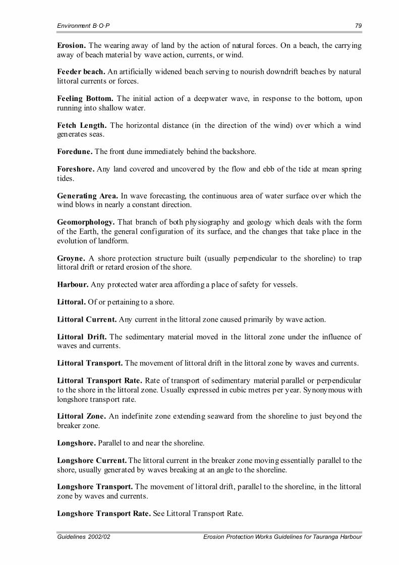
Environment B·O·P 79
Guidelines 2002/02 Erosion Protection Works Guidelines for Tauranga Harbour
Erosion. The wearing away of land by the action of natural forces. On a beach, the carrying away of beach material by wave action, currents, or wind.
Feeder beach. An artificially widened beach serving to nourish downdrift beaches by natural littoral currents or forces.
Feeling Bottom. The initial action of a deepwater wave, in response to the bottom, upon running into shallow water.
Fetch Length. The horizontal distance (in the direction of the wind) over which a wind generates seas.
Foredune. The front dune immediately behind the backshore.
Foreshore. Any land covered and uncovered by the flow and ebb of the tide at mean spring tides.
Generating Area. In wave forecasting, the continuous area of water surface over which the wind blows in nearly a constant direction.
Geomorphology. That branch of both physiography and geology which deals with the form of the Earth, the general configuration of its surface, and the changes that take place in the evolution of landform.
Groyne. A shore protection structure built (usually perpendicular to the shoreline) to trap littoral drift or retard erosion of the shore.
Harbour. Any protected water area affording a place of safety for vessels.
Littoral. Of or pertaining to a shore.
Littoral Current. Any current in the littoral zone caused primarily by wave action.
Littoral Drift. The sedimentary material moved in the littoral zone under the influence of waves and currents.
Littoral Transport. The movement of littoral drift in the littoral zone by waves and currents.
Littoral Transport Rate. Rate of transport of sedimentary material parallel or perpendicular to the shore in the littoral zone. Usually expressed in cubic metres per year. Synonymous with longshore transport rate.
Littoral Zone. An indefinite zone extending seaward from the shoreline to just beyond the breaker zone.
Longshore. Parallel to and near the shoreline.
Longshore Current. The littoral current in the breaker zone moving essentially parallel to the shore, usually generated by waves breaking at an angle to the shoreline.
Longshore Transport. The movement of littoral drift, parallel to the shoreline, in the littoral zone by waves and currents.
Longshore Transport Rate. See Littoral Transport Rate.
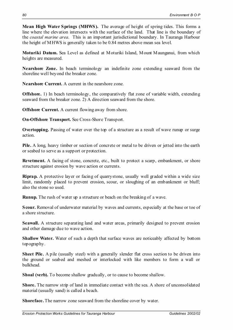
80 Environment B·O·P
Erosion Protection Works Guidelines for Tauranga Harbour Guidelines 2002/02
Mean High Water Springs (MHWS). The average of height of spring tides. This forms a line where the elevation intersects with the surface of the land. That line is the boundary of the coastal marine area. This is an important jurisdictional boundary. In Tauranga Harbour the height of MHWS is generally taken to be 0.84 metres above mean sea level.
Moturiki Datum. Sea Level as defined at Moturiki Island, Mount Maunganui, from which heights are measured.
Nearshore Zone. In beach terminology an indefinite zone extending seaward from the shoreline well beyond the breaker zone.
Nearshore Current. A current in the nearshore zone.
Offshore. 1) In beach terminology, the comparatively flat zone of variable width, extending seaward from the breaker zone. 2) A direction seaward from the shore.
Offshore Current. A current flowing away from shore.
On-Offshore Transport. See Cross-Shore Transport.
Overtopping. Passing of water over the top of a structure as a result of wave runup or surge action.
Pile. A long, heavy timber or section of concrete or metal to be driven or jetted into the earth or seabed to serve as a support or protection.
Revetment. A facing of stone, concrete, etc., built to protect a scarp, embankment, or shore structure against erosion by wave action or currents.
Riprap. A protective layer or facing of quarrystone, usually well graded within a wide size limit, randomly placed to prevent erosion, scour, or sloughing of an embankment or bluff; also the stone so used.
Runup. The rush of water up a structure or beach on the breaking of a wave.
Scour. Removal of underwater material by waves and currents, especially at the base or toe of a shore structure.
Seawall. A structure separating land and water areas, primarily designed to prevent erosion and other damage due to wave action.
Shallow Water. Water of such a depth that surface waves are noticeably affected by bottom topography.
Sheet Pile. A pile (usually steel) with a generally slender flat cross section to be driven into the ground or seabed and meshed or interlocked with like members to form a wall or bulkhead.
Shoal (verb). To become shallow gradually, or to cause to become shallow.
Shore. The narrow strip of land in immediate contact with the sea. A shore of unconsolidated material (usually sand) is called a beach.
Shoreface. The narrow zone seaward from the shoreline cover by water.
Environment B·O·P 81
Guidelines 2002/02 Erosion Protection Works Guidelines for Tauranga Harbour
Shoreline. The intersection of a specified plane of water with the shore or beach.
Slope. The degree of inclination to the horizontal.
Still Water Level. The elevation that the surface of the water would assume if all wave action were absent.
Storm Surge. A rise above normal water level on the open coast due to the action wind stress on the water surface.
Surf. The wave activity in the area between the shoreline and the outermost limit of breakers.
Surf Zone. The area between the outermost breaker and the limit of wave uprush.
Swash. The rush of water up onto the beach face following the breaking of a wave.
Swash Mark. The thin wavy line of fine sand, mica scales, bits of debris, etc., left by the uprush when it recedes from its upward limit of movement on the beach face.
Swell. Wind-generated waves that have travelled out of their generating area.
Topography. The configuration of a surface, including its relief and the positions of its streams, roads, buildings, etc.
Updrift. The direction opposite that of the predominant movement of littoral materials.
Wave. A ridge, deformation, or undulation of the surface of a liquid.
Wave Crest. The highest part of a wave.
Wave Direction The direction from which a wave approaches.
Wave Forecasting. The theoretical determination of future wave characteristics, usually from observed or predicted meteorological phenomena.
Wave Height. The vertical distance between a crest and the preceding trough.
Wave Hindcasting. The use of historic synoptic wind charts to calculate characteristics of waves that probably occurred at some past time.
Wave Length. The horizontal distance between similar points on two successive waves measured perpendicular to the crest.
Wave Period. The time for a wave crest to traverse a distance equal to one wavelength. The time for two successive wave crests to pass a fixed point.
Wave Setup. Superelevation of the water surface over normal surge elevation due to onshore mass transport of the water by wave action alone.
Wave Steepness. The ratio of the wave height to the wavelength.
Wave Trough. The lowest part of a wave between successive crests.
Wind Setup. The vertical rise in the still-water level on the leeward side of a body of water caused by wind stresses on the surface of the water.